EP3513671B1 - Batterieanordnung und elektronische zigarette damit - Google Patents
Batterieanordnung und elektronische zigarette damit Download PDFInfo
- Publication number
- EP3513671B1 EP3513671B1 EP18197826.3A EP18197826A EP3513671B1 EP 3513671 B1 EP3513671 B1 EP 3513671B1 EP 18197826 A EP18197826 A EP 18197826A EP 3513671 B1 EP3513671 B1 EP 3513671B1
- Authority
- EP
- European Patent Office
- Prior art keywords
- button
- button cap
- circuit board
- battery assembly
- elastic member
- Prior art date
- Legal status (The legal status is an assumption and is not a legal conclusion. Google has not performed a legal analysis and makes no representation as to the accuracy of the status listed.)
- Active
Links
Images



Classifications
-
- H—ELECTRICITY
- H01—ELECTRIC ELEMENTS
- H01H—ELECTRIC SWITCHES; RELAYS; SELECTORS; EMERGENCY PROTECTIVE DEVICES
- H01H9/00—Details of switching devices, not covered by groups H01H1/00 - H01H7/00
- H01H9/02—Bases, casings, or covers
- H01H9/06—Casing of switch constituted by a handle serving a purpose other than the actuation of the switch, e.g. by the handle of a vacuum cleaner
-
- A—HUMAN NECESSITIES
- A24—TOBACCO; CIGARS; CIGARETTES; SIMULATED SMOKING DEVICES; SMOKERS' REQUISITES
- A24F—SMOKERS' REQUISITES; MATCH BOXES; SIMULATED SMOKING DEVICES
- A24F40/00—Electrically operated smoking devices; Component parts thereof; Manufacture thereof; Maintenance or testing thereof; Charging means specially adapted therefor
- A24F40/40—Constructional details, e.g. connection of cartridges and battery parts
-
- A—HUMAN NECESSITIES
- A24—TOBACCO; CIGARS; CIGARETTES; SIMULATED SMOKING DEVICES; SMOKERS' REQUISITES
- A24F—SMOKERS' REQUISITES; MATCH BOXES; SIMULATED SMOKING DEVICES
- A24F40/00—Electrically operated smoking devices; Component parts thereof; Manufacture thereof; Maintenance or testing thereof; Charging means specially adapted therefor
- A24F40/60—Devices with integrated user interfaces
-
- H—ELECTRICITY
- H01—ELECTRIC ELEMENTS
- H01M—PROCESSES OR MEANS, e.g. BATTERIES, FOR THE DIRECT CONVERSION OF CHEMICAL ENERGY INTO ELECTRICAL ENERGY
- H01M10/00—Secondary cells; Manufacture thereof
- H01M10/42—Methods or arrangements for servicing or maintenance of secondary cells or secondary half-cells
- H01M10/425—Structural combination with electronic components, e.g. electronic circuits integrated to the outside of the casing
-
- H—ELECTRICITY
- H01—ELECTRIC ELEMENTS
- H01M—PROCESSES OR MEANS, e.g. BATTERIES, FOR THE DIRECT CONVERSION OF CHEMICAL ENERGY INTO ELECTRICAL ENERGY
- H01M50/00—Constructional details or processes of manufacture of the non-active parts of electrochemical cells other than fuel cells, e.g. hybrid cells
- H01M50/20—Mountings; Secondary casings or frames; Racks, modules or packs; Suspension devices; Shock absorbers; Transport or carrying devices; Holders
- H01M50/204—Racks, modules or packs for multiple batteries or multiple cells
- H01M50/207—Racks, modules or packs for multiple batteries or multiple cells characterised by their shape
- H01M50/213—Racks, modules or packs for multiple batteries or multiple cells characterised by their shape adapted for cells having curved cross-section, e.g. round or elliptic
-
- H—ELECTRICITY
- H01—ELECTRIC ELEMENTS
- H01M—PROCESSES OR MEANS, e.g. BATTERIES, FOR THE DIRECT CONVERSION OF CHEMICAL ENERGY INTO ELECTRICAL ENERGY
- H01M50/00—Constructional details or processes of manufacture of the non-active parts of electrochemical cells other than fuel cells, e.g. hybrid cells
- H01M50/20—Mountings; Secondary casings or frames; Racks, modules or packs; Suspension devices; Shock absorbers; Transport or carrying devices; Holders
- H01M50/271—Lids or covers for the racks or secondary casings
-
- H—ELECTRICITY
- H01—ELECTRIC ELEMENTS
- H01M—PROCESSES OR MEANS, e.g. BATTERIES, FOR THE DIRECT CONVERSION OF CHEMICAL ENERGY INTO ELECTRICAL ENERGY
- H01M50/00—Constructional details or processes of manufacture of the non-active parts of electrochemical cells other than fuel cells, e.g. hybrid cells
- H01M50/20—Mountings; Secondary casings or frames; Racks, modules or packs; Suspension devices; Shock absorbers; Transport or carrying devices; Holders
- H01M50/284—Mountings; Secondary casings or frames; Racks, modules or packs; Suspension devices; Shock absorbers; Transport or carrying devices; Holders with incorporated circuit boards, e.g. printed circuit boards [PCB]
-
- A—HUMAN NECESSITIES
- A24—TOBACCO; CIGARS; CIGARETTES; SIMULATED SMOKING DEVICES; SMOKERS' REQUISITES
- A24F—SMOKERS' REQUISITES; MATCH BOXES; SIMULATED SMOKING DEVICES
- A24F40/00—Electrically operated smoking devices; Component parts thereof; Manufacture thereof; Maintenance or testing thereof; Charging means specially adapted therefor
- A24F40/10—Devices using liquid inhalable precursors
-
- H—ELECTRICITY
- H01—ELECTRIC ELEMENTS
- H01H—ELECTRIC SWITCHES; RELAYS; SELECTORS; EMERGENCY PROTECTIVE DEVICES
- H01H9/00—Details of switching devices, not covered by groups H01H1/00 - H01H7/00
- H01H9/02—Bases, casings, or covers
- H01H9/06—Casing of switch constituted by a handle serving a purpose other than the actuation of the switch, e.g. by the handle of a vacuum cleaner
- H01H2009/065—Battery operated hand tools in which the battery and the switch are directly connected
-
- H—ELECTRICITY
- H01—ELECTRIC ELEMENTS
- H01M—PROCESSES OR MEANS, e.g. BATTERIES, FOR THE DIRECT CONVERSION OF CHEMICAL ENERGY INTO ELECTRICAL ENERGY
- H01M2220/00—Batteries for particular applications
- H01M2220/30—Batteries in portable systems, e.g. mobile phone, laptop
-
- Y—GENERAL TAGGING OF NEW TECHNOLOGICAL DEVELOPMENTS; GENERAL TAGGING OF CROSS-SECTIONAL TECHNOLOGIES SPANNING OVER SEVERAL SECTIONS OF THE IPC; TECHNICAL SUBJECTS COVERED BY FORMER USPC CROSS-REFERENCE ART COLLECTIONS [XRACs] AND DIGESTS
- Y02—TECHNOLOGIES OR APPLICATIONS FOR MITIGATION OR ADAPTATION AGAINST CLIMATE CHANGE
- Y02E—REDUCTION OF GREENHOUSE GAS [GHG] EMISSIONS, RELATED TO ENERGY GENERATION, TRANSMISSION OR DISTRIBUTION
- Y02E60/00—Enabling technologies; Technologies with a potential or indirect contribution to GHG emissions mitigation
- Y02E60/10—Energy storage using batteries
Definitions
- the invention relates to a battery assembly and an electronic cigarette using the battery assembly.
- Electronic cigarettes also known as electronic cigarettes, are mainly used to quit smoking and replace conventional cigarettes. It has an appearance and taste similar to conventional cigarettes, and even has more tastes than conventional cigarettes. It can generate smoke, a taste and a feel like conventional cigarettes. Without tar, suspension particles and other harmful components in conventional cigarettes, electronic cigarettes have gradually replaced conventional cigarettes on the market.
- the existing electronic cigarettes supply power to the heat generating unit in the atomizer through the battery assembly, so that the heat generating unit heats the tobacco liquid to generate smoke under the driving of the battery assembly, thereby enabling the user to obtain a smoking experience.
- the battery assembly in the market usually controls the battery assembly by pressing the control button.
- the battery assembly is usually not provided with a stopper to limit the movement stroke of the button assembly.
- the button assembly excessively squeezes the internal trigger component for a long time so that the button assembly is low in service life.
- the pressing force applied by the user is too large, the phenomenon that the button assembly crushes the circuit board is likely to occur.
- CN 206284394 U discloses an electronic cigarette.
- the present invention provides a battery assembly according to claim 1; the present invention also provides an electronic cigarette including the battery assembly according to claim 9.
- Various embodiments are recited in dependent claims.
- the main object of the invention is to provide a battery assembly, which aims to prevent the phenomenon that a large pressing force applied by the user to the button assembly results in a low service life of the button assembly and crushes the circuit board.
- the invention provides a battery assembly comprising a main body, a circuit board mounted in the main body and a button assembly, wherein the main body is provided with an avoidance hole and at least one stopper, the button assembly comprises a button cap and a button contact, the button contact is fixedly mounted in the main body and is electrically connected with the circuit board, and the button cap is slidably mounted in the avoidance hole.
- the button cap slides to squeeze the button contact, the button cap abuts against the stopper to form a trigger position where the button cap triggers the button contact to transmit a control signal to the circuit board.
- An elastic member is further provided between the button cap and the button contact, one of the button cap and the button contact is fixedly connected with the elastic member, and the other thereof elastically abuts against the elastic member.
- one of the button cap and the elastic member is convexly provided with a fixed column, and the other thereof is provided with a groove, the fixed column is inserted into the groove, and the elastic member is fixed to the button cap.
- the button cap is further convexly provided with at least one limiting member, and each of the limiting members abuts against a portion of the outer periphery of the elastic member when the elastic member is fixedly mounted to the button cap.
- the elastic member is further provided with an extending part which elastically abuts against the side structure of the circuit board when the button cap slides to the trigger position.
- one of the extending part and the button cap is provided with a connecting buckle, and the other thereof is provided with a connecting groove, and the connecting buckle is inserted into the connecting groove to fix the extending part to the button cap.
- an end of the button cap facing the button contact is further provided with a flange, when the flange is in contact with the periphery of the avoidance hole, the flange abuts against the periphery of the avoidance hole, thus limiting the button cap to the main body.
- the main body comprises a sleeve, a connecting assembly and an end cover
- the sleeve is provided with a battery chamber for receiving the battery
- the end cover and the connecting assembly are fixedly mounted on both ends of the sleeve, respectively, and block the battery chamber
- the connecting assembly is fixedly connected with the circuit board and is used to connect an external load and conduct the external load and the circuit board
- the avoidance hole is provided on the outer periphery of the sleeve.
- the sleeve is further provided with at least one light-transmitting decorative member around the avoidance hole
- the main body is further provided with at least one light source
- the light source is electrically connected with the circuit board
- the light emitted by the light source is at least partially transmitted from the light-transmitting decorative member
- the connecting assembly comprises a negative electrode connector, an insulating member and a positive electrode conductive column
- the negative electrode connector is provided with a through hole in which an external load is mounted and an avoidance groove in which the button cap reciprocates
- the avoidance groove is convexly provided with at least one stopper
- the insulating member is sleeved on the outer periphery of the positive electrode conductive column and abuts against the inner wall of the through hole
- the positive electrode conductive column is fixed in the through hole
- the circuit board is electrically connected with the positive electrode conductive column and the negative electrode connector.
- the invention further provides an electronic cigarette comprising an atomizer
- the battery assembly comprises a main body, a circuit board mounted in the main body and a button assembly, the main body is provided with an avoidance hole and at least one stopper
- the button assembly comprises a button cap and a button contact
- the button contact is fixedly mounted in the main body and is electrically connected with the circuit board
- the button cap is slidably mounted in the avoidance hole and abuts against the stopper when the button cap slides to squeeze the button contact to form a trigger position and trigger the button contact to transmit a control signal to the circuit board
- one end of the atomizer is fixedly mounted to the battery assembly and is electrically connected with a circuit board provided inside the battery assembly.
- the main body is provided with an avoidance hole and at least one stopper.
- the button cap When the user presses the button cap, the button cap is driven to abut against the stopper when the button cap slides along the avoidance hole to squeeze the button contact.
- the stopper When the user further presses the button cap with an excessive force, the stopper has a limiting supporting force on the button cap, limiting the button cap to further squeeze the button contact, preventing the phenomenon that the deformation of the button contact under the action of a large pressing force during long-term use results in a decreased trigger sensitivity, effectively improving the service life of the button assembly, and preventing the phenomenon that a large pressing force crushes the circuit board.
- first, second, etc. appear in the invention, they are merely for the purpose of description, but cannot be understood as the indication or implication of relative importance or as the implicit indication of the number of the designated technical features; therefore, features defined by “first” and “second” may specifically or implicitly comprise at least one such feature.
- technical solutions of each embodiment of the invention may be combined mutually; however, this must be carried out on the basis that those skilled in the art can implement the combination. When the combination of technical solutions has a conflict or cannot be implemented, it should be considered that such combination of technical solutions does not exist and is not in the scope of protection claimed by the invention.
- fixed may be fixed connection, detachable connection, or integration; may be mechanical connection or electrical connection; direct connection, indirect connection through an intermediate, or internal communication between two elements or interaction of two elements, unless otherwise specifically defined.
- the invention provides a battery assembly 100, which is applied to an electronic cigarette.
- the electronic cigarette comprises an atomizer (not shown).
- An oil storing chamber and a heat generating assembly are provided in the atomizer.
- the battery assembly 100 is provided with a connecting assembly which is fixedly electrically connected with the atomizer, and the circuit board 30 provided in the battery assembly 100 controls the output current of the power supply to supply power to the heat generating assembly in the atomizer, so that the heat generating assembly heats tobacco tar when driven by the battery assembly 100 to generate smoke, thus giving the user a smoking experience.
- the battery assembly 100 is provided with a rechargeable battery element 70 therein, and is provided with a plug-in terminal 31 for charging and data transmission.
- the plug-in terminal 31 may use a micro jack, a lighting jack or a type c jack.
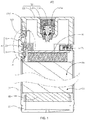
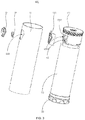
- the battery assembly 100 comprises a main body 10, a circuit board 30 mounted in the main body 10 and a button assembly 50, wherein the main body 10 is provided with an avoidance hole 112 and at least one stopper 1213, the button assembly 50comprises a button cap 51 and a button contact 52, the button contact 52 is fixedly mounted in the main body 10 and is electrically connected with the circuit board 30, and the button cap 51 is slidably mounted in the avoidance hole 112 and abuts against the stopper 1213 when the button cap slides to squeeze the button contact 52 to form a trigger position and trigger the button contact 52 to transmit a control signal to the circuit board 30.
- the button assembly 50 comprises a button cap 51 and a button contact 52
- the button contact 52 is fixedly mounted in the main body 10 and is electrically connected with the circuit board 30
- the button cap 51 is slidably mounted in the avoidance hole 112 and abuts against the stopper 1213 when the button cap slides to squeeze the button contact 52 to form a trigger position and trigger the button
- the main body 10 is provided with an avoidance hole112 and at least one stopper 1213.
- the button cap 51 is driven to abut against the stopper 1213 when the button cap 51 slides along the avoidance hole 112 to squeeze the button contact 52.
- the stopper 1213 When the user further presses the button cap with an excessive force, the stopper 1213 has a limiting supporting force on the button cap 51, limiting the button cap51 to further squeeze the button contact 52, preventing the phenomenon that the deformation of the button contact 52 under the action of a large pressing force during long-term use results in a decreased trigger sensitivity, effectively improving the service life of the button assembly 50, and preventing the phenomenon that a large pressing force crushes the circuit board 30.
- an elastic member 53 is further provided between the button cap 51 and the button contact 52, one of the button cap 51 and the button contact 52 is fixedly connected with the elastic member 53, and the other thereof elastically abuts against the elastic member 53.
- one end of the elastic member 53 is fixed to the button cap 51, and the other end elastically abuts against the button contact, thereby effectively improving the resilience generated when the button cap 51 is released after being pressed, so that the button cap 51 slides toward the outside of the main body 10 along the avoidance hole 112 under the elastic restoring force of the elastic member 53 when not pressed, and is partially exposed to the outside of the main body 10 for the user to press.
- the manner in which the elastic member 53 may use a spring 124, an elastic silicone rubber or elastic plastic to improve the resilience generated when the button cap 51 is released after being pressed falls within the scope of protection of the invention.
- the mounting manner in which one end of the elastic member 53 may also be fixedly connected with the elastic contact, and the other end elastically abuts against the button cap 51 falls within the scope of protection of the invention.
- one of the button cap 51 and the elastic member 53 is convexly provided with a fixed column 511, and the other thereof is provided with a groove 531, the fixed column 511 is inserted into the groove 531, and the elastic member 53 is fixed to the button cap 51.
- the elastic member 53 is made of elastic silicone.
- One end of the button end 51 toward the button contact 52 is convexly provided with a fixed column 511, and then a groove 531 is provided in the elastic silicone.
- the area surrounded by the periphery of the groove 531 is slightly smaller than the surface area surrounded by the outer periphery of the fixed column 511.
- the extruded elastic silicone has a retractable elastic deformation force, so that it is closely sleeved to the fixed column 511, effectively preventing the phenomenon that the elastic member 53 is disengaged from the button cap 51 during the long-term use of the button assembly 50.
- the button cap 51 is further convexly provided with at least one limiting member 512, and each of the limiting members 512 abuts against a portion of the outer periphery of the elastic member 53 when the elastic member 53 is fixedly mounted to the button cap 51.
- the button cap 51 is convexly provided with an annular limiting member 512.
- the elastic limiting member 512 When the elastic member 53 is sleeved to the fixed column 511, the elastic limiting member 512 is sleeved to the outer periphery of the end of the elastic member 53 provided with a groove 531, and the elastic member 53 is partially buckled between the limiting member 512 and the fixed column 511, thereby further preventing the phenomenon that the elastic member 53 is disengaged from the button cap 51 during the long-term use of the button assembly 50.
- the button cap 51 is not limited to preventing the phenomenon that the elastic member 53 is disengaged from the button cap 51 in such a manner that the annular limiting member 512 is convexly provided.
- the button cap 51 may be also convexly provided with a plurality of limiting blocks. The manner in which the limiting blocks are provided at intervals around the fixed column 511 to partially buckle the elastic member 53 between the limiting member 512 and the fixed column 511 to prevent the elastic member 53 from being disengaged from the button cap 51 falls within the scope of protection of the invention.
- one end of the annular limiting block far away from the button cap 51 is further convexly provided with two auxiliary bumps 5121 which abuts against the outer periphery of the elastic member 53, effectively increasing the clamping area with the elastic member 53, and further preventing the phenomenon that the elastic member 53 is disengaged from the button cap 51 during the long-term use of the button assembly 50.
- the elastic member 53 is further provided with an extending part 532 which elastically abuts against the side structure of the circuit board 30 when the button cap 51slides to the trigger position.
- the elastic member 53 is further provided with an extending part 532.
- one of the extending part 532 and the button cap 51 is provided with a connecting buckle 5321, and the other thereof is provided with a connecting groove 514, and the connecting buckle 5321 is inserted into the connecting groove 514 to fix the extending part 532 to the button cap 51.
- one end of the extending part 532 far away from the groove 531 isconvexly provided with a connecting buckle 5321
- the button cap 51 is provided with a connecting groove 514
- the connecting buckle 5321 is fastened to the connecting groove 514
- one end of the extending part 532 far away from the groove 531 is fixed to the button cap 51, thereby effectively preventing the phenomenon that the elastic member 53 is disengaged from the button cap 51 due to the misalignment of the extending part 532during the long-term use.
- the extending part 532 and the button cap 51 are not limited to the manner in which a connecting buckle 5321 and a connecting groove 514 are provided to be fastened and connected.
- a fastener such as a screw
- a plurality of buckles and necks are fastened, or one end of the extending part 532 far away from the groove 531 extends away from the button cap 51 to abut against the circuit board 30, and the extending part 532 abuts against the outer surface of the button cap 51 may also be used. All the manners fall within the scope of protection of the invention.
- the end of the button cap 51 toward the button contact 52 is further provided with a flange 513, which abuts when being in contact with the periphery of the avoidance hole 112 to limit the button cap51 to the main body 10.
- the end of the button cap 51 toward the button contact 52 is further provided with a flange 513.
- the button cap 51 slides along the avoidance hole 112 from the outside of the main body 10 to the flange 513 under the elastic restoring force of the elastic member 53 to abut against the periphery of the avoidance hole 112, thereby effectively preventing the phenomenon that the button cap 51 is disengaged from the main body 10.
- the main body 10 comprises a sleeve 11, a connecting assembly 12 and an end cover 13, the sleeve 11 is provided with a battery chamber 111 for receiving the battery 70, the end cover 13 and the connecting assembly 12 are fixedly mounted on both ends of the sleeve 11, respectively, and block the battery chamber 111, the connecting assembly 12 is fixedly connected with the circuit board 30 and is used to connect an external load and conduct the external load and the circuit board 30, and the avoidance hole 112 is provided on the outer periphery of the sleeve 11.
- the main body 10 is generally in the shape of a rod.
- the sleeve 11 is provided with a battery chamber 111 for receiving the battery 70.
- the end cover 13 is fixedly connected with the sleeve 11 by a thread and blocks the battery chamber 111.
- the connecting assembly 12 is fixedly mounted on an end of the sleeve 11 far away from the end cover 13.
- the circuit board 30 is mounted in the sleeve 11 and is fixedly connected with the connecting assembly 12 by a screw, thereby effectively preventing the circuit board 30 from shaking, and facilitating the wiring of the circuit board 30 and the connecting assembly 12, effectively saving mounting space and reducing product volume.
- the sleeve 11 is further provided with at least one light-transmitting decorative member 113 around the avoidance hole 112
- the main body 10 is further provided with at least one light source, the light source is electrically connected with the circuit board 30, and the light emitted by the light source is at least partially transmitted from the light-transmitting decorative member 113.
- a plurality of LED light sources are integrated on the circuit board 30, the plurality of LED light sources are arranged on both surfaces of the circuit board 30 toward the connecting assembly 12 and far away from the connecting assembly 12, and the light emitted from each of the LED light sources is at least partially transmitted from the light-transmitting decorative member 113, thereby preventing the light from being shielded by the circuit board 30 or other components, resulting in a phenomenon that the light transmitted through the light-transmitting decorative member 113 has different luminosities.
- the control circuit provided by the circuit board 30 controls each of the LED light sources to emit light to generate an indication effect, effectively reminding the user of the operating state of the battery assembly100.
- both ends of the battery 70 are further provided with a covering member 60.
- the covering member 60 is made of foam, effectively preventing the phenomenon that the hard contact between both ends of the battery 70 results in crushing short circuit.
- the circuit board 30 is electrically connected with a plug-in terminal 31 for electrically charging and transmitting data inside the battery chamber 111.
- the outer periphery of the sleeve 11 is correspondingly provided with a plug-in interface exposing the plug-in terminal 31.
- the plug-in terminal 31 is provided so that the user can perform charging without disassembling the internal battery 70, which greatly facilitates the ease of use of the user.
- the connecting assembly 12 comprises a negative electrode connector 121, an insulating member 122 and a positive electrode conductive column 123
- the negative electrode connector 121 is provided with a through hole 1211 in which an external load is mounted and an avoidance groove 1212 in which the button cap 51 reciprocates
- the avoidance groove 1212 is convexly provided with at least one stopper 1213
- the insulating member 122 is sleeved on the outer periphery of the positive electrode conductive column 123 and abuts against the inner wall of the through hole 1211
- the positive electrode conductive column 123 is fixed in the through hole 1211
- the circuit board 30 is electrically connected with the positive electrode conductive column 123 and the negative electrode connector 121.
- the negative electrode connector 121 comprises a first tube body (not labeled), a second tube body (not labeled) provided in the first tube body, and a connecting plate (not labeled) connecting the first tube body and the second tube body.
- a part of the outer periphery of the first tube body is provided at irregular pattern bone position (not labeled), and is convenient to abut against and clamp the inner wall of the sleeve 11 in an interference fit.
- the first sleeve 11 is provided with an avoidance groove 1212 in which the button cap 51 reciprocates.
- the stopper 1213 is convexly provided in the inner groove wall of the avoidance groove 1212 to be machine-shaped with the negative electrode connector 121 integrally, which is convenient to process and takes up small space.
- the second sleeve 11 forms a through hole 1211 in which an external load is mounted.
- the inner wall of the through hole 1211 is provided with a connecting thread (not labeled).
- the insulating member 122 is sleeved on the positive electrode conductive column 123 and abuts against the inner wall of the through hole 1211.
- the positive electrode conductive column 123 is fixed to the through hole 1211.
- the circuit board 30 is electrically connected with the positive electrode conductive column 123 and the negative electrode connector 121.
- the negative electrode conductive end of the external load is fixedly electrically connected with the negative electrode connector 121 through a connecting screw.
- the positive electrode conductive end elastically abuts against the positive electrode conductive column 123 to form an electrical circuit, thereby effectively ensuring the stability of the power supply.
- the invention further provides an electronic cigarette, wherein the electronic cigarette comprises an atomizer and a battery assembly 100.
- the electronic cigarette comprises an atomizer and a battery assembly 100.
- the battery assembly 100 Due to the use of all the technical solutions of all the above embodiments, the electronic cigarette has at least all the beneficial effects brought by the technical solutions of the above embodiments, which will not be described in detail herein.
Landscapes
- Chemical & Material Sciences (AREA)
- Chemical Kinetics & Catalysis (AREA)
- Electrochemistry (AREA)
- General Chemical & Material Sciences (AREA)
- Engineering & Computer Science (AREA)
- Human Computer Interaction (AREA)
- Microelectronics & Electronic Packaging (AREA)
- Manufacturing & Machinery (AREA)
- Battery Mounting, Suspending (AREA)
Claims (9)
- Batteriebaugruppe mit einem Hauptkörper (10), einer im Hauptkörper (10) montierten Leiterplatte (30) und einer Tastenbaugruppe (50), wobei der Hauptkörper (10) mit einem Ausweichloch (112) versehen ist,
wobei die Tastenbaugruppe (50) eine Tastenkappe (51) und einen Tastenkontakt (52) aufweist, wobei der Tastenkontakt (52) fest im Hauptkörper (10) montiert und elektrisch mit der Leiterplatte (30) verbunden ist, und die Tastenkappe (51) ist verschiebbar in dem Ausweichloch (112) angebracht,
wobei ferner ein elastisches Element (53) zwischen der Tastenkappe (51) und dem Tastenkontakt (52) vorgesehen ist, wobei eines von der Tastenkappe (51) und von dem Tastenkontakt (52) fest mit dem elastischen Element (53) verbunden ist und das andere elastisch an dem elastischen Element (53) anliegt;
dadurch gekennzeichnet, dass
der Hauptkörper (10) mit mindestens einem Stopper (1213) versehen ist und, wenn die Tastenkappe (51) gleitet, um den Tastenkontakt (52) zusammenzudrücken, liegt die Tastenkappe (51) an dem Stopper (1213) an, um eine Auslöseposition zu schaffen, in der die Tastenkappe (51) den Tastenkontakt (52) auslöst, um ein Steuersignal an die Leiterplatte (30) zu übertragen,
wobei das elastische Element (53) ferner mit einem Verlängerungsteil (532) versehen ist, wobei, wenn die Tastenkappe (51) in die Auslöseposition gleitet, das Verlängerungsteil (532) elastisch gegen eine Seitenstruktur der Leiterplatte (30) stößt. - Batteriebaugruppe nach Anspruch 1, wobei eine von der Tastenkappe (51) und von dem elastischen Element (53) konvex mit einer festen Säule (511) versehen ist und die andere mit einer Nut (531) versehen ist, die feste Säule (511) in die Nut (531) eingeführt ist, so dass das elastische Element (53) an der Tastenkappe (51) befestigt ist.
- Batteriebaugruppe nach Anspruch 2, wobei die Tastenkappe (51) weiterhin konvex mit mindestens einem Begrenzungselement (512) versehen ist, wobei, wenn das elastische Element (53) fest an der Tastenkappe (51) montiert ist, jedes der Begrenzungselemente (512) an einem Abschnitt eines Außenumfangs des elastischen Elements (53) anliegt.
- Batteriebaugruppe nach Anspruch 1, wobei eine von dem Verlängerungsteil (532) und von der Tastenkappe (51) mit einer Verbindungsschnalle (5321) versehen sind und die andere mit einer Verbindungsnut (514) versehen ist, und die Verbindungsschnalle (5321) in die Verbindungsnut (514) eingeführt ist, um das Verlängerungsteil (532) an der Tastenkappe (51) zu befestigen.
- Batteriebaugruppe nach Anspruch 1, wobei ein Ende der Tastenkappe (51), das dem Tastenkontakt (52) zugewandt ist, ferner mit einem Flansch (513) versehen ist, wobei, wenn der Flansch (513) mit der Öffnung des Ausweichlochs (112) in Kontakt steht, der Flansch (513) an der Öffnung des Ausweichlochs (112) anliegt, wodurch die Tastenkappe (51) auf den Hauptkörper (10) begrenzt ist.
- Batterieanordnung nach einem der Ansprüche 1 bis 5, wobei der Hauptkörper (10) eine Hülse (11), eine Verbindungsanordnung (12) und eine Endabdeckung (13) aufweist, wobei die Hülse (11) mit einer Batteriekammer (111) zur Aufnahme der Batterie (70) versehen ist, der Endabdeckung (13) und die Verbindungsanordnung (12) sind jeweils an beiden Enden der Hülse (11) fest angebracht und blockieren die Batteriekammer (111), die Verbindungsanordnung (12) ist fest mit der Leiterplatte (30) verbunden und dient zum Verbinden einer externen Last und zum elektrischen Verbinden der externen Last und der Leiterplatte (30), und das Ausweichloch (112) ist am Außenumfang der Hülse (11) vorgesehen.
- Batteriebaugruppe nach Anspruch 6, wobei die Verbindungsanordnung (12) einen negativen Elektrodenverbinder (121), ein Isolierelement und eine positive Elektrodenleitersäule (123) aufweist, wobei der negative Elektrodenverbinder (121) mit einem Durchgangsloch (1211), in dem ein externe Last montiert ist, und mit einer Ausweichnut (1212) versehen ist, in der sich die Tastenkappe (51) hinundher bewegt, die Ausweichnut (1212) ist konvex mit mindestens einem Stopper (1213) versehen, wobei das Isolierelement nach Art einer Hülse am Außenumfang der positiven Elektrodenleitersäule (123) angebracht ist und an der Innenwand des Durchgangslochs (1211) anliegt, die positive Elektrodenleitersäule (123) ist in dem Durchgangsloch (1211) befestigt und die Leiterplatte (30) ist elektrisch mit der positiven Elektrodenleitersäule (123) und der negativen Elektrodenverbinder (121) verbunden.
- Batteriebaugruppe nach Anspruch 6, wobei die Hülse (11) ferner mit mindestens einem lichtdurchlässigen dekorativen Element (113) um das Ausweichloch (112) herum versehen ist, und der Hauptkörper (10) ferner mit mindestens einer Lichtquelle versehen ist, die Lichtquelle ist elektrisch mit der Leiterplatte (30) verbunden, und das von der Lichtquelle emittierte Licht ist zumindest teilweise von dem lichtdurchlässigen dekorativen Element (113) übertragen.
- Elektronische Zigarette mit einem Zerstäuber, wobei die elektronische Zigarette ferner die Batteriebaugruppe (100) nach einem der Ansprüche 1 bis 8 umfasst, und ein Ende des Zerstäubers fest an der Batteriebaugruppe (100) angebracht und elektrisch mit einer Leiterplatte (30) verbunden ist, die in der Batterieanordnung (100) vorgesehen ist.
Applications Claiming Priority (1)
| Application Number | Priority Date | Filing Date | Title |
|---|---|---|---|
| CN201820104782.7U CN207855045U (zh) | 2018-01-19 | 2018-01-19 | 供电组件及电子烟 |
Publications (2)
| Publication Number | Publication Date |
|---|---|
| EP3513671A1 EP3513671A1 (de) | 2019-07-24 |
| EP3513671B1 true EP3513671B1 (de) | 2020-04-08 |
Family
ID=63462701
Family Applications (1)
| Application Number | Title | Priority Date | Filing Date |
|---|---|---|---|
| EP18197826.3A Active EP3513671B1 (de) | 2018-01-19 | 2018-10-01 | Batterieanordnung und elektronische zigarette damit |
Country Status (4)
| Country | Link |
|---|---|
| US (1) | US11508536B2 (de) |
| EP (1) | EP3513671B1 (de) |
| CN (1) | CN207855045U (de) |
| CA (1) | CA3020114C (de) |
Families Citing this family (8)
| Publication number | Priority date | Publication date | Assignee | Title |
|---|---|---|---|---|
| CN209090065U (zh) * | 2018-09-30 | 2019-07-12 | 深圳市艾维普思科技有限公司 | 电子烟的导电接触件的安装结构及电子烟 |
| US11089820B2 (en) * | 2018-10-12 | 2021-08-17 | Tuanfang Liu | Electronic cigarette comprising sealed atomizing assembly |
| US11489227B2 (en) * | 2018-11-06 | 2022-11-01 | Tuanfang Liu | Electronic cigarette |
| CA3103590C (en) * | 2019-10-15 | 2021-12-07 | Canopy Growth Corporation | Vaporizer charging structure |
| KR20240046182A (ko) * | 2021-08-13 | 2024-04-08 | 제이티 인터내셔널 소시에떼 아노님 | 흡입 디바이스 및 흡입 디바이스를 제작하는 방법 |
| CN113662260B (zh) * | 2021-08-24 | 2023-11-03 | 深圳市真味生物科技有限公司 | 一种便于提高戒烟效果的电子烟 |
| CN115813029A (zh) * | 2021-09-17 | 2023-03-21 | 深圳市奇艺谷科技有限公司 | 一种可调式带有感应灯的电子烟 |
| US20250134166A1 (en) * | 2021-11-04 | 2025-05-01 | Philip Morris Products S.A. | Aerosol-generating device with button centering |
Family Cites Families (9)
| Publication number | Priority date | Publication date | Assignee | Title |
|---|---|---|---|---|
| US9399110B2 (en) * | 2011-03-09 | 2016-07-26 | Chong Corporation | Medicant delivery system |
| US9913950B2 (en) * | 2011-03-09 | 2018-03-13 | Chong Corporation | Medicant delivery system |
| KR20120007263U (ko) * | 2011-04-13 | 2012-10-23 | (주)데캉코리아 | 카트리지 일체형 전자담배 |
| KR101285213B1 (ko) * | 2011-06-23 | 2013-07-11 | 신종수 | 전자담배 |
| US10039321B2 (en) * | 2013-11-12 | 2018-08-07 | Vmr Products Llc | Vaporizer |
| CN204015114U (zh) * | 2014-07-29 | 2014-12-17 | 深圳市艾维普思科技有限公司 | 一种用于电子烟中的电池按键结构 |
| KR101696363B1 (ko) * | 2014-12-16 | 2017-01-13 | 신종수 | 전자 담배 |
| KR101772344B1 (ko) * | 2016-10-19 | 2017-09-12 | 주식회사 이씨엠 | 전자담배 |
| CN206284394U (zh) * | 2016-11-04 | 2017-06-30 | 深圳市艾维普思科技股份有限公司 | 电子烟 |
-
2018
- 2018-01-19 CN CN201820104782.7U patent/CN207855045U/zh active Active
- 2018-10-01 EP EP18197826.3A patent/EP3513671B1/de active Active
- 2018-10-09 CA CA3020114A patent/CA3020114C/en active Active
- 2018-10-13 US US16/159,615 patent/US11508536B2/en active Active
Non-Patent Citations (1)
| Title |
|---|
| None * |
Also Published As
| Publication number | Publication date |
|---|---|
| US11508536B2 (en) | 2022-11-22 |
| CN207855045U (zh) | 2018-09-14 |
| EP3513671A1 (de) | 2019-07-24 |
| CA3020114A1 (en) | 2019-07-19 |
| US20190223501A1 (en) | 2019-07-25 |
| CA3020114C (en) | 2021-08-24 |
Similar Documents
| Publication | Publication Date | Title |
|---|---|---|
| CA3020114C (en) | Battery assembly and electronic cigarette having same | |
| CA3020137C (en) | Conductive contact structure, battery assembly and electronic cigarette having same | |
| TWM546606U (zh) | 線纜連接器組件 | |
| EP3590366B1 (de) | Heizvorrichtung und elektronische zigarette damit | |
| CN110454754A (zh) | 灯头及其灯座 | |
| US10362691B2 (en) | Touch-controlling device, functional expansion member thereof, and USB socket connector | |
| US6777890B1 (en) | Cylindrical miniature-LED light-emitting device | |
| CN212014438U (zh) | 电子烟 | |
| CN208129433U (zh) | 供电组件及电子烟 | |
| US20210212365A1 (en) | Battery assembly | |
| CN222503918U (zh) | 一种带发光棒的打火机 | |
| CN208076951U (zh) | 一种具有导光结构的按键及使用该按键的开关接收器 | |
| CN217876260U (zh) | 一种改进型雾化组件及雾化加湿器 | |
| CN210662924U (zh) | 一种带灯的电弧点火枪 | |
| CN215645179U (zh) | 一种密封接触件结构 | |
| CN211556345U (zh) | 一种具有发光导向结构的嵌入式插座 | |
| CN109990236B (zh) | 一种镜子灯 | |
| CN216844226U (zh) | 灯具组件及具有其的可拼接灯具 | |
| JPH058880U (ja) | 高周波コネクタ | |
| CN218826724U (zh) | 一种带灯启动熄火开关 | |
| CN218586530U (zh) | 一种智能转换插座 | |
| CN221698874U (zh) | 一种自行车带灯座管结构 | |
| CN214074208U (zh) | 一种筋膜枪 | |
| CN216113477U (zh) | 一种中部开关充电并列型电筒 | |
| GB2211924A (en) | Electric torch |
Legal Events
| Date | Code | Title | Description |
|---|---|---|---|
| PUAI | Public reference made under article 153(3) epc to a published international application that has entered the european phase |
Free format text: ORIGINAL CODE: 0009012 |
|
| STAA | Information on the status of an ep patent application or granted ep patent |
Free format text: STATUS: REQUEST FOR EXAMINATION WAS MADE |
|
| 17P | Request for examination filed |
Effective date: 20181023 |
|
| AK | Designated contracting states |
Kind code of ref document: A1 Designated state(s): AL AT BE BG CH CY CZ DE DK EE ES FI FR GB GR HR HU IE IS IT LI LT LU LV MC MK MT NL NO PL PT RO RS SE SI SK SM TR |
|
| AX | Request for extension of the european patent |
Extension state: BA ME |
|
| GRAP | Despatch of communication of intention to grant a patent |
Free format text: ORIGINAL CODE: EPIDOSNIGR1 |
|
| STAA | Information on the status of an ep patent application or granted ep patent |
Free format text: STATUS: GRANT OF PATENT IS INTENDED |
|
| INTG | Intention to grant announced |
Effective date: 20191030 |
|
| GRAS | Grant fee paid |
Free format text: ORIGINAL CODE: EPIDOSNIGR3 |
|
| GRAA | (expected) grant |
Free format text: ORIGINAL CODE: 0009210 |
|
| STAA | Information on the status of an ep patent application or granted ep patent |
Free format text: STATUS: THE PATENT HAS BEEN GRANTED |
|
| AK | Designated contracting states |
Kind code of ref document: B1 Designated state(s): AL AT BE BG CH CY CZ DE DK EE ES FI FR GB GR HR HU IE IS IT LI LT LU LV MC MK MT NL NO PL PT RO RS SE SI SK SM TR |
|
| REG | Reference to a national code |
Ref country code: CH Ref legal event code: EP Ref country code: AT Ref legal event code: REF Ref document number: 1253160 Country of ref document: AT Kind code of ref document: T Effective date: 20200415 |
|
| REG | Reference to a national code |
Ref country code: DE Ref legal event code: R096 Ref document number: 602018003623 Country of ref document: DE |
|
| REG | Reference to a national code |
Ref country code: IE Ref legal event code: FG4D |
|
| REG | Reference to a national code |
Ref country code: NL Ref legal event code: MP Effective date: 20200408 |
|
| REG | Reference to a national code |
Ref country code: LT Ref legal event code: MG4D |
|
| PG25 | Lapsed in a contracting state [announced via postgrant information from national office to epo] |
Ref country code: NO Free format text: LAPSE BECAUSE OF FAILURE TO SUBMIT A TRANSLATION OF THE DESCRIPTION OR TO PAY THE FEE WITHIN THE PRESCRIBED TIME-LIMIT Effective date: 20200708 Ref country code: GR Free format text: LAPSE BECAUSE OF FAILURE TO SUBMIT A TRANSLATION OF THE DESCRIPTION OR TO PAY THE FEE WITHIN THE PRESCRIBED TIME-LIMIT Effective date: 20200709 Ref country code: IS Free format text: LAPSE BECAUSE OF FAILURE TO SUBMIT A TRANSLATION OF THE DESCRIPTION OR TO PAY THE FEE WITHIN THE PRESCRIBED TIME-LIMIT Effective date: 20200808 Ref country code: SE Free format text: LAPSE BECAUSE OF FAILURE TO SUBMIT A TRANSLATION OF THE DESCRIPTION OR TO PAY THE FEE WITHIN THE PRESCRIBED TIME-LIMIT Effective date: 20200408 Ref country code: FI Free format text: LAPSE BECAUSE OF FAILURE TO SUBMIT A TRANSLATION OF THE DESCRIPTION OR TO PAY THE FEE WITHIN THE PRESCRIBED TIME-LIMIT Effective date: 20200408 Ref country code: PT Free format text: LAPSE BECAUSE OF FAILURE TO SUBMIT A TRANSLATION OF THE DESCRIPTION OR TO PAY THE FEE WITHIN THE PRESCRIBED TIME-LIMIT Effective date: 20200817 Ref country code: NL Free format text: LAPSE BECAUSE OF FAILURE TO SUBMIT A TRANSLATION OF THE DESCRIPTION OR TO PAY THE FEE WITHIN THE PRESCRIBED TIME-LIMIT Effective date: 20200408 Ref country code: LT Free format text: LAPSE BECAUSE OF FAILURE TO SUBMIT A TRANSLATION OF THE DESCRIPTION OR TO PAY THE FEE WITHIN THE PRESCRIBED TIME-LIMIT Effective date: 20200408 |
|
| REG | Reference to a national code |
Ref country code: AT Ref legal event code: MK05 Ref document number: 1253160 Country of ref document: AT Kind code of ref document: T Effective date: 20200408 |
|
| PG25 | Lapsed in a contracting state [announced via postgrant information from national office to epo] |
Ref country code: HR Free format text: LAPSE BECAUSE OF FAILURE TO SUBMIT A TRANSLATION OF THE DESCRIPTION OR TO PAY THE FEE WITHIN THE PRESCRIBED TIME-LIMIT Effective date: 20200408 Ref country code: LV Free format text: LAPSE BECAUSE OF FAILURE TO SUBMIT A TRANSLATION OF THE DESCRIPTION OR TO PAY THE FEE WITHIN THE PRESCRIBED TIME-LIMIT Effective date: 20200408 Ref country code: BG Free format text: LAPSE BECAUSE OF FAILURE TO SUBMIT A TRANSLATION OF THE DESCRIPTION OR TO PAY THE FEE WITHIN THE PRESCRIBED TIME-LIMIT Effective date: 20200708 Ref country code: RS Free format text: LAPSE BECAUSE OF FAILURE TO SUBMIT A TRANSLATION OF THE DESCRIPTION OR TO PAY THE FEE WITHIN THE PRESCRIBED TIME-LIMIT Effective date: 20200408 |
|
| PG25 | Lapsed in a contracting state [announced via postgrant information from national office to epo] |
Ref country code: AL Free format text: LAPSE BECAUSE OF FAILURE TO SUBMIT A TRANSLATION OF THE DESCRIPTION OR TO PAY THE FEE WITHIN THE PRESCRIBED TIME-LIMIT Effective date: 20200408 |
|
| REG | Reference to a national code |
Ref country code: DE Ref legal event code: R097 Ref document number: 602018003623 Country of ref document: DE |
|
| PG25 | Lapsed in a contracting state [announced via postgrant information from national office to epo] |
Ref country code: IT Free format text: LAPSE BECAUSE OF FAILURE TO SUBMIT A TRANSLATION OF THE DESCRIPTION OR TO PAY THE FEE WITHIN THE PRESCRIBED TIME-LIMIT Effective date: 20200408 Ref country code: AT Free format text: LAPSE BECAUSE OF FAILURE TO SUBMIT A TRANSLATION OF THE DESCRIPTION OR TO PAY THE FEE WITHIN THE PRESCRIBED TIME-LIMIT Effective date: 20200408 Ref country code: DK Free format text: LAPSE BECAUSE OF FAILURE TO SUBMIT A TRANSLATION OF THE DESCRIPTION OR TO PAY THE FEE WITHIN THE PRESCRIBED TIME-LIMIT Effective date: 20200408 Ref country code: SM Free format text: LAPSE BECAUSE OF FAILURE TO SUBMIT A TRANSLATION OF THE DESCRIPTION OR TO PAY THE FEE WITHIN THE PRESCRIBED TIME-LIMIT Effective date: 20200408 Ref country code: EE Free format text: LAPSE BECAUSE OF FAILURE TO SUBMIT A TRANSLATION OF THE DESCRIPTION OR TO PAY THE FEE WITHIN THE PRESCRIBED TIME-LIMIT Effective date: 20200408 Ref country code: RO Free format text: LAPSE BECAUSE OF FAILURE TO SUBMIT A TRANSLATION OF THE DESCRIPTION OR TO PAY THE FEE WITHIN THE PRESCRIBED TIME-LIMIT Effective date: 20200408 Ref country code: CZ Free format text: LAPSE BECAUSE OF FAILURE TO SUBMIT A TRANSLATION OF THE DESCRIPTION OR TO PAY THE FEE WITHIN THE PRESCRIBED TIME-LIMIT Effective date: 20200408 Ref country code: ES Free format text: LAPSE BECAUSE OF FAILURE TO SUBMIT A TRANSLATION OF THE DESCRIPTION OR TO PAY THE FEE WITHIN THE PRESCRIBED TIME-LIMIT Effective date: 20200408 |
|
| PLBE | No opposition filed within time limit |
Free format text: ORIGINAL CODE: 0009261 |
|
| STAA | Information on the status of an ep patent application or granted ep patent |
Free format text: STATUS: NO OPPOSITION FILED WITHIN TIME LIMIT |
|
| PG25 | Lapsed in a contracting state [announced via postgrant information from national office to epo] |
Ref country code: SK Free format text: LAPSE BECAUSE OF FAILURE TO SUBMIT A TRANSLATION OF THE DESCRIPTION OR TO PAY THE FEE WITHIN THE PRESCRIBED TIME-LIMIT Effective date: 20200408 Ref country code: PL Free format text: LAPSE BECAUSE OF FAILURE TO SUBMIT A TRANSLATION OF THE DESCRIPTION OR TO PAY THE FEE WITHIN THE PRESCRIBED TIME-LIMIT Effective date: 20200408 |
|
| REG | Reference to a national code |
Ref country code: DE Ref legal event code: R082 Ref document number: 602018003623 Country of ref document: DE Representative=s name: SCHMID, MICHAEL, DIPL.-ING. UNIV., DE |
|
| 26N | No opposition filed |
Effective date: 20210112 |
|
| PG25 | Lapsed in a contracting state [announced via postgrant information from national office to epo] |
Ref country code: SI Free format text: LAPSE BECAUSE OF FAILURE TO SUBMIT A TRANSLATION OF THE DESCRIPTION OR TO PAY THE FEE WITHIN THE PRESCRIBED TIME-LIMIT Effective date: 20200408 |
|
| PG25 | Lapsed in a contracting state [announced via postgrant information from national office to epo] |
Ref country code: MC Free format text: LAPSE BECAUSE OF FAILURE TO SUBMIT A TRANSLATION OF THE DESCRIPTION OR TO PAY THE FEE WITHIN THE PRESCRIBED TIME-LIMIT Effective date: 20200408 Ref country code: LU Free format text: LAPSE BECAUSE OF NON-PAYMENT OF DUE FEES Effective date: 20201001 |
|
| REG | Reference to a national code |
Ref country code: BE Ref legal event code: MM Effective date: 20201031 |
|
| PG25 | Lapsed in a contracting state [announced via postgrant information from national office to epo] |
Ref country code: BE Free format text: LAPSE BECAUSE OF NON-PAYMENT OF DUE FEES Effective date: 20201031 |
|
| PG25 | Lapsed in a contracting state [announced via postgrant information from national office to epo] |
Ref country code: IE Free format text: LAPSE BECAUSE OF NON-PAYMENT OF DUE FEES Effective date: 20201001 |
|
| REG | Reference to a national code |
Ref country code: CH Ref legal event code: PL |
|
| PG25 | Lapsed in a contracting state [announced via postgrant information from national office to epo] |
Ref country code: TR Free format text: LAPSE BECAUSE OF FAILURE TO SUBMIT A TRANSLATION OF THE DESCRIPTION OR TO PAY THE FEE WITHIN THE PRESCRIBED TIME-LIMIT Effective date: 20200408 Ref country code: MT Free format text: LAPSE BECAUSE OF FAILURE TO SUBMIT A TRANSLATION OF THE DESCRIPTION OR TO PAY THE FEE WITHIN THE PRESCRIBED TIME-LIMIT Effective date: 20200408 Ref country code: CY Free format text: LAPSE BECAUSE OF FAILURE TO SUBMIT A TRANSLATION OF THE DESCRIPTION OR TO PAY THE FEE WITHIN THE PRESCRIBED TIME-LIMIT Effective date: 20200408 |
|
| PG25 | Lapsed in a contracting state [announced via postgrant information from national office to epo] |
Ref country code: MK Free format text: LAPSE BECAUSE OF FAILURE TO SUBMIT A TRANSLATION OF THE DESCRIPTION OR TO PAY THE FEE WITHIN THE PRESCRIBED TIME-LIMIT Effective date: 20200408 |
|
| PG25 | Lapsed in a contracting state [announced via postgrant information from national office to epo] |
Ref country code: LI Free format text: LAPSE BECAUSE OF NON-PAYMENT OF DUE FEES Effective date: 20211031 Ref country code: CH Free format text: LAPSE BECAUSE OF NON-PAYMENT OF DUE FEES Effective date: 20211031 |
|
| PGFP | Annual fee paid to national office [announced via postgrant information from national office to epo] |
Ref country code: DE Payment date: 20251027 Year of fee payment: 8 |
|
| PGFP | Annual fee paid to national office [announced via postgrant information from national office to epo] |
Ref country code: GB Payment date: 20251030 Year of fee payment: 8 |
|
| PGFP | Annual fee paid to national office [announced via postgrant information from national office to epo] |
Ref country code: FR Payment date: 20251027 Year of fee payment: 8 |