EP3513596B1 - Radio resource management and routing for fixed data circuits in an ngso satellite data communications system - Google Patents
Radio resource management and routing for fixed data circuits in an ngso satellite data communications system Download PDFInfo
- Publication number
- EP3513596B1 EP3513596B1 EP17886994.7A EP17886994A EP3513596B1 EP 3513596 B1 EP3513596 B1 EP 3513596B1 EP 17886994 A EP17886994 A EP 17886994A EP 3513596 B1 EP3513596 B1 EP 3513596B1
- Authority
- EP
- European Patent Office
- Prior art keywords
- satellite
- ground terminal
- time interval
- circuit
- uplink
- Prior art date
- Legal status (The legal status is an assumption and is not a legal conclusion. Google has not performed a legal analysis and makes no representation as to the accuracy of the status listed.)
- Active
Links
- 238000004891 communication Methods 0.000 title claims description 67
- 230000006870 function Effects 0.000 claims description 49
- 238000000034 method Methods 0.000 claims description 33
- 230000008859 change Effects 0.000 claims description 16
- 238000010200 validation analysis Methods 0.000 claims description 12
- 230000004907 flux Effects 0.000 claims description 4
- 238000004590 computer program Methods 0.000 claims 2
- 230000005540 biological transmission Effects 0.000 description 23
- 238000007726 management method Methods 0.000 description 17
- 238000013459 approach Methods 0.000 description 15
- 238000010586 diagram Methods 0.000 description 12
- 238000012545 processing Methods 0.000 description 12
- 230000008569 process Effects 0.000 description 11
- 235000008694 Humulus lupulus Nutrition 0.000 description 10
- 230000000116 mitigating effect Effects 0.000 description 8
- 230000003287 optical effect Effects 0.000 description 7
- 230000001105 regulatory effect Effects 0.000 description 6
- 230000007774 longterm Effects 0.000 description 5
- 101100339496 Caenorhabditis elegans hop-1 gene Proteins 0.000 description 4
- 230000003466 anti-cipated effect Effects 0.000 description 4
- 230000003068 static effect Effects 0.000 description 4
- 230000010287 polarization Effects 0.000 description 3
- 238000012360 testing method Methods 0.000 description 3
- 230000002411 adverse Effects 0.000 description 2
- 238000004364 calculation method Methods 0.000 description 2
- 230000001413 cellular effect Effects 0.000 description 2
- 238000012217 deletion Methods 0.000 description 2
- 230000037430 deletion Effects 0.000 description 2
- 238000013461 design Methods 0.000 description 2
- 230000007246 mechanism Effects 0.000 description 2
- 230000006855 networking Effects 0.000 description 2
- 238000012546 transfer Methods 0.000 description 2
- 238000003491 array Methods 0.000 description 1
- 230000008901 benefit Effects 0.000 description 1
- 230000002457 bidirectional effect Effects 0.000 description 1
- 239000000969 carrier Substances 0.000 description 1
- 238000010276 construction Methods 0.000 description 1
- 230000008878 coupling Effects 0.000 description 1
- 238000010168 coupling process Methods 0.000 description 1
- 238000005859 coupling reaction Methods 0.000 description 1
- 230000001934 delay Effects 0.000 description 1
- 238000011161 development Methods 0.000 description 1
- 230000008030 elimination Effects 0.000 description 1
- 238000003379 elimination reaction Methods 0.000 description 1
- 235000003642 hunger Nutrition 0.000 description 1
- 238000005286 illumination Methods 0.000 description 1
- 238000012423 maintenance Methods 0.000 description 1
- 238000012986 modification Methods 0.000 description 1
- 230000004048 modification Effects 0.000 description 1
- 238000012544 monitoring process Methods 0.000 description 1
- 230000002093 peripheral effect Effects 0.000 description 1
- 230000003362 replicative effect Effects 0.000 description 1
- 230000004044 response Effects 0.000 description 1
- 239000007787 solid Substances 0.000 description 1
- 238000001228 spectrum Methods 0.000 description 1
- 230000001360 synchronised effect Effects 0.000 description 1
- 238000012795 verification Methods 0.000 description 1
Images


Classifications
-
- H—ELECTRICITY
- H04—ELECTRIC COMMUNICATION TECHNIQUE
- H04W—WIRELESS COMMUNICATION NETWORKS
- H04W40/00—Communication routing or communication path finding
- H04W40/02—Communication route or path selection, e.g. power-based or shortest path routing
- H04W40/026—Route selection considering the moving speed of individual devices
-
- H—ELECTRICITY
- H04—ELECTRIC COMMUNICATION TECHNIQUE
- H04B—TRANSMISSION
- H04B7/00—Radio transmission systems, i.e. using radiation field
- H04B7/14—Relay systems
- H04B7/15—Active relay systems
- H04B7/185—Space-based or airborne stations; Stations for satellite systems
- H04B7/195—Non-synchronous stations
-
- H—ELECTRICITY
- H04—ELECTRIC COMMUNICATION TECHNIQUE
- H04B—TRANSMISSION
- H04B7/00—Radio transmission systems, i.e. using radiation field
- H04B7/14—Relay systems
- H04B7/15—Active relay systems
- H04B7/185—Space-based or airborne stations; Stations for satellite systems
- H04B7/18521—Systems of inter linked satellites, i.e. inter satellite service
-
- H—ELECTRICITY
- H04—ELECTRIC COMMUNICATION TECHNIQUE
- H04B—TRANSMISSION
- H04B7/00—Radio transmission systems, i.e. using radiation field
- H04B7/14—Relay systems
- H04B7/15—Active relay systems
- H04B7/185—Space-based or airborne stations; Stations for satellite systems
- H04B7/18578—Satellite systems for providing broadband data service to individual earth stations
- H04B7/18584—Arrangements for data networking, i.e. for data packet routing, for congestion control
-
- H—ELECTRICITY
- H04—ELECTRIC COMMUNICATION TECHNIQUE
- H04L—TRANSMISSION OF DIGITAL INFORMATION, e.g. TELEGRAPHIC COMMUNICATION
- H04L45/00—Routing or path finding of packets in data switching networks
- H04L45/22—Alternate routing
-
- H—ELECTRICITY
- H04—ELECTRIC COMMUNICATION TECHNIQUE
- H04L—TRANSMISSION OF DIGITAL INFORMATION, e.g. TELEGRAPHIC COMMUNICATION
- H04L45/00—Routing or path finding of packets in data switching networks
- H04L45/24—Multipath
- H04L45/243—Multipath using M+N parallel active paths
-
- H—ELECTRICITY
- H04—ELECTRIC COMMUNICATION TECHNIQUE
- H04W—WIRELESS COMMUNICATION NETWORKS
- H04W84/00—Network topologies
- H04W84/02—Hierarchically pre-organised networks, e.g. paging networks, cellular networks, WLAN [Wireless Local Area Network] or WLL [Wireless Local Loop]
- H04W84/04—Large scale networks; Deep hierarchical networks
- H04W84/06—Airborne or Satellite Networks
Definitions
- the present invention relates to radio resource management and data packet routing for fixed data circuits in non-geostationary orbit (NGSO) wireless data communications systems, such as low earth orbit (LEO) satellite data communications systems.
- NGSO non-geostationary orbit
- LEO low earth orbit
- Conventional multi-beam communications satellites e.g., spot beam satellites
- high altitude platforms HAPs
- satellite/HAP antennae generate a configuration of fixed beams radiated by the antennae, where the fixed beams are preconfigured on the satellite/HAP and sweep across the ground as the satellite/HAP moves though its orbit or flight pattern.
- a user terminal is thus served sequentially by the different beams as the fixed beams sweep across the geographic site or cell where the terminal is located.
- the period of a satellite orbit is determined by the altitude of the orbit. For a satellite at about 1200 km altitude the orbital period is less than two hours. Further, in the case where the satellite employs narrow beams for high gain, the user terminal experiences a beam handover as often as every 10 to 20 seconds, where each handover requires a change in frequency and polarization on the part of the terminal, which has to be synchronized at the satellite.
- An example of a radio resource management function of a satellite communications network is described in document US5826169A .
- NGSO non-geostationary orbit
- the data packets for such communications must be routed from the source satellites servicing the cell within which the source terminal is located (for the duration of the data communications) to the respective destination satellites servicing the cell within which the destination terminal is located (for the duration of the data communications).
- NGSO non-geostationary orbit
- the data communications will require differing levels of route complexity, potentially involving a number of satellites and a number of gateways, in order for the respective data packets to traverse a wide geographic distance between the source and destination terminals.
- the extent of the routing complexity would depend on the number of satellites and gateways required to transmit the packets of the data communications from the source terminal to the destination terminal.
- the data communications may only require transferring the respective data packets from the source satellites to the destination satellites via two hops, through the ground gateway servicing the source and destination satellites, while they are servicing the respective source and destination terminals (as would be understood, in view of the transitory nature of a LEO satellite system, at different points in time a different source satellite will be servicing the source terminal and a different destination satellite will be servicing the destination terminal).
- the routing of the respective data communications packets may be required to traverse a combination of a number of satellites and a number of gateways in order to traverse such a wide geographic distance.
- the data packets may have to traverse a number of satellite-gateway-satellite hops to traverse the geographic distance.
- the route processing overhead become significant, and also the multiple satellite-gateway hops introduce significant delay in the packet transmissions between the two terminal endpoints of the circuit.
- NGSO non-geostationary orbit
- LEO low earth orbit
- the present invention advantageously addresses the foregoing requirements and needs, as well as others, by providing a system and methods for efficient radio resource management and routing functions to support long-term or relatively permanent data communications circuits between two geographically diverse endpoint terminals in a non-geostationary orbit (NGSO) wireless data communications system, such as a low earth orbit (LEO) satellite system.
- NGSO non-geostationary orbit
- LEO low earth orbit
- a method for determining a plurality of routes for a committed bit rate data communications circuit between a source ground terminal and a destination ground terminal.
- the circuit is formed via a plurality of satellites, each traveling in a respective non-geostationary orbit around the Earth, and a total time during which the circuit is active is divided into a plurality of time intervals of equal duration.
- the determination of the plurality of routes comprises (i) selecting, for each time interval, an uplink satellite of the constellation to service the source ground terminal as an ingress node for the circuit, and (ii) determining, for each time interval, a series of inter-satellite links connecting the uplink satellite selected for the respective time interval to a downlink satellite of the constellation servicing the destination ground terminal during the respective time interval, wherein the series of inter-satellite links is determined so that it will be valid for connection of the circuit between the uplink ground terminal and the downlink ground terminal during the respective time interval.
- the duration of each interval of the plurality of time intervals is based on a time of validity, based on the traveling of the plurality of satellites in their respective orbits, for a one of the inter-satellite links of all of the plurality of routes that is of the shortest duration.
- a system for providing one or more committed bit rate data communications circuits each between a respective source ground terminal and a respective destination ground terminal.
- Each circuit is formed via a plurality of satellites, each traveling in a respective non-geostationary orbit around the Earth, and a total time during which the circuit is active is divided into a plurality of time intervals of equal duration.
- the determination of the plurality of routes comprises (i) selecting, for each time interval, an uplink satellite of the constellation to service the source ground terminal as an ingress node for the circuit, and (ii) determining, for each time interval, a series of inter-satellite links connecting the uplink satellite selected for the respective time interval to a downlink satellite of the constellation servicing the destination ground terminal during the respective time interval, wherein the series of inter-satellite links is determined so that it will be valid for connection of the circuit between the uplink ground terminal and the downlink ground terminal during the respective time interval.
- the duration of each interval of the plurality of time intervals is based on a time of validity, based on the traveling of the plurality of satellites in their respective orbits, for a one of the inter-satellite links of all of the plurality of routes that is of the shortest duration.
- the antennae of each satellite may be configured to form communications beams to illuminate a fixed/stationary pattern of cells on the ground as the satellite travels through its orbit.
- the satellite is configured to generate rapidly time varying beams, with different scan angles, beam shapes and directivities, in order to illuminate the respective fixed/stationary ground-based cell pattern. While the beam/footprint of a satellite moves across the surface of the Earth relative to the movement of the satellite, the cells remain stationary or fixed (each satellite antenna continually adjusts the relative cell pattern of its respective beam to maintain a fixed/stationary cell pattern on the surface of the Earth - as the satellite moves, the satellite will continually service the cells of that cell pattern that are within the footprint of the satellite antenna beam).
- a phased array antenna is employed on satellite, and the satellite is configured to dynamically determine the appropriate beamforming coefficients or weights, over given time intervals, in order to generate time varying beam patterns that illuminate the respective stationary cells on the ground.
- each such ground-based cell may be assigned a fixed frequency/polarization (F/P) pair.
- F/P frequency/polarization
- the communications platform moves, it forms the communications beams to illuminate the respective stationary cell pattern, where each cell is assigned a respective F/P pair.
- a ground terminal located within a given cell utilizes a constant F/P pair for the fixed cell within which it is located irrespective of the satellite that is servicing the cell.
- NGSO non-geostationary orbit
- LEO low earth orbit
- the present invention is not intended to be limited based on the described embodiments, and various modifications will be readily apparent. It will be apparent that the invention may be practiced without the specific details of the following description and/or with equivalent arrangements. Additionally, well-known structures and devices may be shown in block diagram form in order to avoid unnecessarily obscuring the invention. Further, the specific applications discussed herein are provided only as representative examples, and the principles described herein may be applied to other embodiments and applications without departing from the general scope of the present invention.
- a module or component may be composed of software component(s), which are stored in a memory or other computer-readable storage medium, and executed by one or more processors or CPUs of the respective devices.
- a module may alternatively be composed of hardware component(s) or firmware component(s), or a combination of hardware, firmware and/or software components.
- the methods, processes and approaches described herein may be processor-implemented using processing circuitry that may comprise one or more microprocessors, application specific integrated circuits (ASICs), field programmable gate arrays (FPGAs), or other devices operable to be configured or programmed to implement the systems and/or methods described herein.
- processing circuitry may comprise one or more microprocessors, application specific integrated circuits (ASICs), field programmable gate arrays (FPGAs), or other devices operable to be configured or programmed to implement the systems and/or methods described herein.
- ASICs application specific integrated circuits
- FPGAs field programmable gate arrays
- the flow diagrams and methods described herein may be implemented in processor instructions stored in a computer-readable medium, such as executable software stored in a computer memory store.
- Non-volatile media include, for example, optical disk media, magnetic disk media or electrical disk media (e.g., solid state disk or SDD).
- Volatile media include dynamic memory, such random access memory or RAM.
- Computer-readable media include, for example, floppy or flexible disk, hard disk, magnetic tape, any other magnetic medium, CD ROM, CDRW, DVD, any other optical medium, random access memory (RAM), programmable read only memory (PROM), erasable PROM, flash EPROM, any other memory chip or cartridge, or any other medium from which a computer can read data.
- RAM random access memory
- PROM programmable read only memory
- PROM erasable PROM
- flash EPROM any other memory chip or cartridge, or any other medium from which a computer can read data.
- FIG. 1A illustrates an example satellite communications system (e.g., a LEO satellite system) for employing routing approaches for fixed data circuits, in accordance with example embodiments of the present invention.
- a satellite communications system e.g., a LEO satellite system
- NGSO non-geosynchronous orbit
- LEO low earth orbit
- MEO medium earth orbit
- HAP high altitude platform
- the satellite communications system 100 includes a plurality of satellites 101, which may hereinafter be referred to as a constellation.
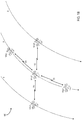
- the satellites of the constellation travel around the Earth 103 in different orbital planes, such as the orbital planes a and b depicted in FIG. 1A .
- the satellites 101a1, 101a2, 101a3 travel in the orbital plane a
- the satellites 101b1, 101b2, 101b3 travel in the orbital plane b (an orbital plane may also be referred to herein simply as a plane or orbit).
- an orbital plane the satellites may be distributed at relatively even distances apart so that the angular position between each adjacent pair of satellites is substantially uniform, and the orbital planes may be highly inclined relative to the equator to provide global coverage (e.g., the angle formed between the orbital plane and the equatorial plane is greater than 70 degrees).
- the orbital planes may also distributed in a substantially uniform manner.
- a satellite in accordance with example embodiments employs a multiple beam antenna (e.g., a phased array antenna) that illuminates a respective geographic region or footprint on the surface of the Earth, such as the regions 105a1, 105a2, 105a3, 105b2 of the satellites 101a1, 101a2, 101a3, 101b2, respectively.
- a multiple beam antenna e.g., a phased array antenna
- the footprint/beam moves across the surface of the Earth relative to the movement of the satellite.
- Each geographic region illuminated by a satellite antenna is further divided into spot beams or cells 107.
- Each spot beam or cell provides data communication services to the respective ground terminals 111 located within that cell.
- the cells remain stationary or fixed (each satellite antenna continually adjusts the relative cell pattern of its respective beam to maintain a uniform cell pattern on the surface of the Earth - as the satellite moves, the satellite will continually service the cells of that cell pattern that are within the footprint of the satellite antenna beam). More specifically, considering the satellite 101a1 (for example), as the satellite travels through its orbit, the satellite will service the cells 107a1 while those cells are within the footprint of the respective satellite antenna beam.
- the cell 107alx (within which the terminal 111a is located) will become positioned at the edge of the satellite beam 105a1, and the link margin for the services provided to the terminal 111a will diminish).
- the satellite 101a2 will have moved into a position where the cell 107alx is now within the footprint of its antenna beam, and that cell can be transitioned to the satellite 101a2 for the duration of time that the cell is within the footprint of that satellite (now labeled in the Figure as cell 107a2x).
- the terminal 111a it remains in the same cell (the same frequency and polarization), but the communications services for the cell are transitioned from satellite to satellite (in this case, from the satellite 101a1 to the satellite 101a2).
- a handoff or handover will be performed transferring the service for the terminal 111a from the cell 107alx of the satellite 101a1 two the cell 107a2x of the satellite 101a2 (effectively the same cell, but serviced by a new satellite).
- each satellite also may employ one or more inter-satellite links (ISLs) providing for data communications between that satellite and neighboring satellite, such as the ISL 121a between the satellites 101a2 and 101a3 and the ISL 121b between the satellites 101a2 and 101b2.
- ISLs inter-satellite links
- FIG. 1B illustrates a diagram of one example where each satellite (e.g., as shown in the Figure for the satellite 101y2) employs a total of four inter-satellite links (ISLs) between itself and neighboring satellites, in accordance with example embodiments of the present invention.
- ISLs inter-satellite links
- the satellite 101y2 (within the orbital plane y) has an active ISL 151 with the satellite 101y3 directly behind it in the same orbital plane, has an active ISL 153 with the satellite 101y1 directly ahead of it in the same orbital plane, has an active ISL 155 with the satellite 101z1 in the orbital plane z directly to its left (from the perspective of the satellite 101y2 moving downwards in the orbital plane, as indicated by the arrow at the end of the dashed line reflecting the orbital plane y), and has an active ISL 157 with the satellite 101x1 in the orbital plane x directly to its right (again, from the perspective of the satellite 101y2 moving downwards in its orbital plane).
- the adjacent satellites ahead of and behind that satellite remain constant, and thus the ISLs between adjacent satellites within an orbital plane can remain constant.
- the ISLs between satellites in adjacent parallel orbital planes depending on the positions of two adjacent satellites (at a given point in time) within their respective orbital planes and the respective locations of those orbital planes around the earth, the length of time that a given ISL between two such satellites will vary.
- the network operations center of the system will have relatively accurate knowledge of the positions of each satellite within the constellation at all times.
- the provided system and methods employ radio resource management and routing functions to provide long-term or relatively permanent data communications circuits between two geographically diverse network terminals 111.
- the system comprises a constellation of NGSO satellites (e.g., LEO satellites, MEO satellites or a combination of LEO and MEO satellites) in at least one orbital plane operating in at least one altitude.
- the system comprises a constellation of satellites configured with a plurality of NGSO satellites in each of multiple orbital planes, where the satellites are spaced around each orbital plane, and the multiple orbital planes are spaced at various inclinations around the earth, in order to provide global satellite coverage over the relative entire surface of the Earth.
- the system further comprises a network processing function (which could be centralized, distributed, or in the cloud) configured to determine and control the radio resource management in the routing functions of the network, and a plurality of user satellite terminals (UTs) configured to communicate with one another via data communications services provided by the satellite constellation and the network processing function.
- the data communications between the UTs are carried directly between the UTs via the satellite constellation (or via a combination of the satellite constellation and one or more intermediate gateways), based on a plurality of routing tables determined and provided by via an algorithm configured to address the continually changing routes among the constellation of satellites within the network.
- a routing table comprises a list of routes, with each route having a valid period and each route consisting of a set of "next hops" to go from the source terminal to at least one destination terminal.
- the valid period for example, might be expressed as a fixed duration of, say, one second, or as a start and end time, say 3:00PM to 3:11PM on a given date.
- the system may be configured to employ a fixed reuse pattern on the ground and a resource management function, which would significantly simplify capacity plan computations based on, for example, elimination of the need to compute interference.
- the provided approaches facilitate the provision of a carrier-grade data communications service or circuit (e.g., a committed information rate circuit/service) between a UT or user network interface (UNI) and at least one other UT or UNI, where the "carrier-grade” implies a high availability, low latency, low error rate connection that remains continuous even as the satellites move and the respective packet data routes of the circuit continually change.
- FIG. 2A illustrates a diagram of a data communications circuit 211 between a one terminal 111a and a further terminal 111b via the NGSO (e.g., LEO) satellite constellation 213, in accordance with example embodiments of the present invention.
- NGSO e.g., LEO
- the terminals 111a, 111b may each serve as a user network interface (UNI) through which a plurality of network users access the network and provided services (e.g., the data communications services provided by one or more circuits 211).
- the circuit 211 may comprise a point to point Ethernet virtual circuit (EVC) through the satellite constellation 213.
- EVC Ethernet virtual circuit
- each UNI may be located at a very small aperture terminal (VSAT) or a gateway terminal (GW), or a UNI may alternatively be an additional network entirely.
- the service may comprise a UNI to UNI service or a UNI to external network-network interface (ENNI) service.
- multiple satellites are in view at all times (e.g., with fully deployed satellite constellations), and inter-satellite links (ISLs) and Gateways move traffic between satellites as needed.
- ISLs inter-satellite links
- Gateways move traffic between satellites as needed.
- MEF metro Ethernet forum
- FIG. 2B illustrates diagram of an MEF circuit framework via two separate NGSO (e.g., LEO) satellite constellations 222, 224, in accordance with example embodiments of the present invention.
- NGSO e.g., LEO
- Each of the end-user subscribers 231, 233 accesses the respective UNI 221, 229 via a respective network interface 232, 234.
- the network interfaces 232, 234 consist of direct interfaces or connections. According to further embodiments, however, such interfaces may be via a LAN or WAN, which may be via a terrestrial, satellite or other type of network.
- a carrier ethernet circuit 226 is provided between the UNI 221 and the ENNI 225 via the constellation 222, and a carrier ethernet circuit 228 is provided between the ENNI 227 and the UNI 229 via the constellation 224.
- the ENNIs 225, 227 interface with each other via the external network-network interface 223.
- a single constellation may provide the carrier ethernet circuits between two edge UNIs.
- the particular protocol pursuant to which the circuit is provided need not necessarily be the Ethernet protocol, but rather may take the form of any networking protocol or layer of protocols capable of facilitating such carrier grade circuits.
- an end-user subscriber site interfaces with the network via a respective protocol interface at an UNI configured or assigned to serve as an ingress/egress point for accessing the network from that end-user subscriber site.
- the satellite antenna With a traditional LEO satellite, the satellite antenna generates a fixed cell pattern within the antenna footprint, according to the antenna geometry and coefficients applied to the phased array antenna elements, within the antenna coordinate system - meaning that the cell pattern is fixed relative to the illumination of the beams at the satellite phased array antenna. As such, because the cell pattern is fixed relative to the antenna coordinate system, as the satellite travels in its orbit, the cell pattern moves across the face of the earth.
- the particular servicing a given terminal will change rapidly and the respective shape of each cell will vary relative to the angle of inclination of the satellite beam and the distance of the satellite from the earth (as the orbit of a satellite is not necessarily circular and is typically more elliptical in shape, and thus the angle of inclination of the satellite beam relative to the Earth and the distance of the satellite from the Earth changes throughout the orbital path). Accordingly, as mentioned above, with such a traditional LEO satellite, the frequency of handovers for a given terminal is relatively high.
- the satellite and satellite antenna may instead generate dynamically varying spot beams that illuminate a fixed cell pattern on the surface of the Earth, which remains stationary as the satellite travels over respective coverage areas on the surface of the Earth.
- the particular cell servicing a given terminal remains constant for a substantially longer period of time, and thus the frequency of handovers is significantly reduced.
- a cell layout created by each satellite of a satellite system constellation may comprise a contiguous pattern of hexagonal cells covering a respective geographic region on the Earth's surface.
- a fixed reuse pattern may be employed amongst the cells, where the reuse pattern satisfies requirements for mitigating interference between cells and satisfies all applicable regulatory rules (e.g., spectrum usage, maximum power flux density limitations, etc.) and other applicable rules/requirements.
- a nearly constant capacity density is provided across the cell patterns of each satellite footprint, which in turn could facilitate a committed information rate (CIR) service over a particular circuit throughout all periods of time that the circuit is operational, and such a service may be established anywhere within the system.
- CIR committed information rate
- the pattern and capacity density allocation may remain relatively uniform throughout the system life, or the cell sizes and respective capacity density allocation may evolve as the satellite constellation matures over time (e.g., as the business matures, and demand increases, the cell patterns can be redefined over time to meet the maturing business requirements/demands.
- the provided approaches accommodate the addition/deletion of customers and the addition/deletion of circuits for a given customer.
- the overall resource management and the routing tables for the existing circuits can be redefined to accommodate the added circuits and increased bandwidth (e.g., to accommodate modified load balancing to avoid overloading any nodes of the system during respective periods of time).
- the table is generated from a central computer, or alternatively via a distributed computing architecture (e.g., a cloud-based architecture), and then distributed to the UTs and GWs.
- a distributed computing architecture e.g., a cloud-based architecture
- variations may include storage in the satellite or generation in a more distributed fashion.
- the embodiments described herein address a system employing a constellation of satellites utilizing a fixed ground-based spot beam or cell pattern approach.
- such satellite antennae generate dynamically varying spot beams (relative to the plane of the satellite antenna or the satellite antenna coordinate system) that illuminate a fixed cell pattern on the surface of the Earth, which remains stationary as the satellite travels over respective coverage areas on the surface of the Earth.
- a service and routing function which facilitates the establishment and maintenance of fixed circuits between geographically diverse ground terminals, whereby (for a given circuit) the routing function determines and specifies a series of routes over time, where each route specifies a valid route between two respective terminal endpoints for a respective period of time.
- the radio resource management (RRM) function may create a quasi-static uplink capacity plan for the entire network, which is quasi-static from the perspective of the UNI (the ingress/egress GWs or UTs with which the customer is networked or interfaces for access to its assigned circuits).
- the RRM function provides an uplink burst plan for each UNI of the network, which allocates a specific time plan for uplink bursts to each satellite with which the UNI will be communicating during a respective period of time.
- the operation of the uplink capacity planning and the uplink burst assignments to the UNIs of the network is discussed in further detail below.
- the uplink traffic of a UT is at a steady rate independent of satellite positions.
- the RRM may also accommodate some degree of variability on top of the plan, for example, supporting new terminals and some bandwidth on demand.
- downlink traffic from any given satellite and the destination ground terminal may be dynamic without a plan, where distributed congestion management may be applied to minimize packet loss.
- distributed congestion management may be applied to minimize packet loss.
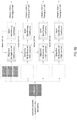
- FIG. 3A illustrates an example route for data communications from one end-user subscriber 331 to another end-user subscriber 333, during a first period of time, via a fixed circuit between two UNIs 111a, 111b, through an NGSO (e.g., a LEO) satellite constellation 100, in accordance with example embodiments of the present invention.
- FIG. 3B illustrates an example route for the data communications of FIG. 3B , from the one end-user subscriber 331 to the other end-user subscriber 333, during a second period of time, via the same fixed circuit between the two UNIs 111a, 111b, in accordance with example embodiments of the present invention.
- 3A and 3B reflect data communications of an end-user subscriber from the end-user subscriber site one 331 (e.g., located in New York) to the site two 333 (e.g., located in London).
- the end-user subscriber site one interfaces with the network via the UNI 111a (e.g., via network facility such as a LAN or WAN) and the end-user subscriber site two interfaces with the network via the UNI 111b (e.g., also via network facility such as a LAN or WAN).
- the end-user subscriber may have contracted with the system operator or service provider for a permanent circuit (e.g., contracted for a particular contract period and guaranteed bandwidth or constant information rate between the New York and London sites 331, 333). Further, in an alternate example, the circuit between these two sites may have been contracted for operation only during business hours in New York (e.g., Monday through Friday, 9 to 5). In any event, for that circuit, each of the respective UNIs 111a, 111b must know the appropriate routes for data packets to traverse the satellite constellation 100 between them at any given time during the operable period for the circuit.
- each of the UNIs 111a, 111b will have a route table corresponding to that particular circuit between the end-user sites 331, 333, which contains a list of routes providing each particular route that will be valid, and that should be used for data packet transmissions over the circuit, during a respective period of time, and covering every period of time that the circuit is required to be available.
- the UNI will have a route table that specifies, from one point in time to the next, the appropriate route for data packets received by the UNI for transmission over the respective circuit.
- a single UNI may be servicing multiple circuits respectively for one or more end-user subscribers, with each circuit being to a different UNI at a different geographically diverse location, where that UNI will have a routing table for each such circuit.
- the UNI 111a will apply the respective route from the route table corresponding to that circuit that is valid for the first period of time.
- the route table will list the satellite 101a1 as the first-hop destination, the satellite 101b1 as the second-hop destination, the satellite 101b2 as the third-hop destination, the satellite 101c2 as the fourth-hop destination, the satellite 101c1 as the fifth-hop destination, and the UNI 111b as the sixth-hop destination.
- the route table will include an appropriate address or other indicator identifying the respective destination satellite or terminal node.
- the UNI 111a will append a header to the packet indicating the series of hops for the route, and will then transfer the packet with the route header to the satellite 101a1 as the first-hop destination.
- the route header will identify the next hop destination to the satellite 101a1.
- the satellite 101a1 Upon receipt of the packet, the satellite 101a1 will decode the header to determine the next hop destination (the second-hop destination - the satellite 101b1), will modify the route header in a manner to identify the next hop destination from the satellite 101b1 (the third-hop destination - the satellite 101b2), and will transmit the packet (with the modified header) to the satellite 101b1.
- the satellite 101b1 Upon receipt of the packet, the satellite 101b1 similarly will decode the header to determine the next hop destination (the third-hop destination -the satellite 101b2), will modify the route header in a manner to identify the next hop destination from the satellite 101b2 (the fourth-hop destination - the satellite 101c2), and will transmit the packet (with the modified header) to the satellite 101b2. This progression of the packet will continue until it reaches the satellite 101c1, which will decode the header to determine the next hop destination as the UNI 111b, and will download the packet to the UNI 111b. The UNI 111b will then transmit the packet to the end-user subscriber site 333 based on an ultimate destination address (e.g., a destination IP address).
- an ultimate destination address e.g., a destination IP address
- the respective satellite may strip (or otherwise nullify) the header information relative to the route hop to the next satellite in the route so that (as received by that next satellite) the next hop route destination will effectively be the first hop destination relative to that next satellite in the route - the next satellite of the route does not need the header information based on which the packet arrived at that satellite, but rather only needs the information for the next hop destination from that satellite.
- Next hop routing is well understood in the industry.
- the UNI 111a will then apply the respective route from the route table corresponding to that circuit that is valid for the second period of time. For that route, the route table will list the satellite 101a1 as the first-hop destination, the satellite 101b2 as the second-hop destination, the satellite 101c3 as the third-hop destination, and the UNI 111b as the fourth-hop destination.
- the ISLs between the respective satellites to complete the circuit have changed, and thus the route for that period of time will traverse a different series of satellites, as indicated by the route entry for that circuit during the second period of time.
- this link may not have been chosen for that circuit route during the first period of time for one or more of a number of particular reasons. For example, that particular ISL may not have been chosen for that period of time because of a determined potential overload of the ISL at that time.
- Various factors considered in determining the particular routes for any given period of time are discussed in further detail below.
- the following table reflects a route table that would be stored at the UNI 111b for all routes, during all applicable time periods, for the same circuit in the other direction to the UNI 111a.
- each UNI serving as an ingress point to the satellite constellation will be provided with, and store within its memory, respective routing table for each circuit defined between it and a further UNI serving as an egress point from the satellite constellation. Further, the routes stored in a routing table for a particular circuit between two UNIs (one UNI serving as an ingress point to the satellite constellation and a second UNI serving as an egress point from the satellite constellation) will continually change over time as the satellites servicing the respective UNIs change and as the ISLs between the satellites of the constellation change.
- each UNI will be provided with, and store within its memory, an uplink burst time plan providing timing/synchronization information as to when to transmit the data packets of the circuits serviced by the UNI. Further, according to example embodiments, each UNI can synchronize with a given satellites servicing that UNI at any given point in time based on any known synchronization method, such as synchronization based on ephemeris information provided by the satellites.
- a gateway may serve as an intermediate node or hop destination within the route.
- the next route may be specified as a downlink to a gateway in communication with the satellite during the respective period of time for that route.
- the satellite would modify the header route information for the data packet to specify the next hop from the gateway as, for example, a next satellite hop destination in the route, and would downlink the packet (with the modified header) to that gateway hop destination.
- the gateway Upon receipt of the data packet, the gateway would similarly modify the header route information for the packet and transmit the packet (with the modified header) to the next satellite hop destination, whereby the header would identify and appropriate further satellite hop or a downlink to the destination UNI (in the event that the satellite was the last satellite/hop of the route) as the next hop.
- the RRM function provides an uplink burst plan for each UNI of the network, which allocates a specific time plan for uplink bursts to each satellite with which the UNI will be communicating during a respective period of time.
- the uplink burst scheduling for a particular UNI in its capacity as an ingress UNI for various circuits of various respective end-users subscribers
- the uplink burst time plan for that UNI will include the required assignment of uplink bursts to satisfy the bandwidth/information-rate as contracted for by the customer.
- the overall uplink burst scheduling for the system would also be orchestrated to accommodate for various system factors, including the satellite availability for each UNI satellite terminal of the system at any given point in time, and the current load of each satellite available to each such UNI at a given point in time (including the overall load of the satellite beam within which the UNI is located and the current load of each of the ISLs of that satellite) in order to avoid congestion and overloading of any given satellite transmission channel or link.
- various other system factors may impact the uplink burst scheduling for each UNI in the network. With further regard to the uplink bursts schedule for the system, that schedule will change over time to accommodate additional circuits of existing or new end-user subscribers and the termination of existing circuits as the system demand evolves.
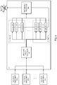
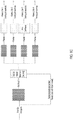
- FIG. 4 illustrates a diagram of the processing performed by a UNI satellite terminal for input data packets received by that UNI and destined for uplink to various respective circuits of end-user subscribers serviced by that UNI, in accordance with example embodiments of the present invention.
- the end-user subscribers 431a to 431n interface with the UNI 111 for transmission of data packets via the circuits A to X serviced by the UNI 111.
- the data packets input to the UNI 111 from the respective end-user subscribers are received by the input data packet processor 401.
- the input data packet processor processes the received packets, and based on header information of each packet, the input data packet processor determines which particular circuit the packet is destined for (one of the circuits CIRCUIT A, ..., CIRCUIT X) and determines a respective priority level for the packet within a range of priority levels of data packets for the respective circuit. Based on the determined circuit and respective priority level, the input data packet processor forwards each packet to a respective queue for packets of that circuit and priority level combination.
- an each packet of the CIRCUIT is forwarded to a respective queue based on its determine priority level (one of the queues A1, A2, ..., An), and similarly for each of the other circuits.
- the transmission processor 405 controls the dequeueing of the data packets from the respective queues and the processing of the data packets for transmission, and once processed for transmission, the transmission processor transmits the packets via the UNI antenna 311 for uplink to a respective satellite.
- the transmission processor 405 dequeues the packets from the respective queues based on circuit priority and packet priority within that circuit. Further, the transmission processor may also take other factors into account when dequeueing the packets, such as congestion control and avoidance of queue overflows.
- each data packet may simply be process based only on the respective circuit over which that packet is to be transmitted. In that case, each circuit will have only one queue, and the packets will be dequeued from the respective queues based on priorities between the respective circuits.
- various alternative methods for processing cueing and transmitting packets may be implemented without departing from the scope of example embodiments of the present invention.
- the downlink is performed in a point and shoot manner as each packet is processed and ready for downlink by the respective satellite.
- the satellite simply transmits the packet within the next available time slot of the downlink spot beam for the cell within which that UNI is located.
- the downlink cell pattern may also be of a fixed nature, for example, with respect to frequency reuse in order to satisfy requirements for mitigating interference between cells and to satisfy applicable regulatory rules.
- terrestrial RRM minimizes the satellite requirements and creates a cleaner functional break, which significantly reduces system roll-out and testing time.
- service demands may justify or require a dynamic downlink, where data rate may be controlled at the ingress UNI, but it does not dictate the data rate of the egress UNI. Even a static ingress can produce highly variable egress.
- point and shoot may be ideal for this. Further, point and shoot, combined with adjacent cells being served by different satellites, may dictate a fixed cellular reuse pattern.
- errors may occur in data packet timing, for example, whereby a data packet may arrive at a respective satellite hop either early or late such that the respective next hop route is no longer or is not yet available. Such early and late arrivals may occur under a variety of different scenarios.
- uplink timing may be in error, for example, whereby (i) the uplink UNI terminal processes the data packet based on an anticipated delay in its queueing structure (for an anticipated transmission time) in inserts the route information for that anticipated transmission time, and (ii) if in operation the packet dequeues early or late, the packet may arrive at a satellite node within the route early or late such that the ISL to the next satellite hop may no longer be available or the uplink to the first hop satellite may no longer be available.
- the ISL timing may be in error, for example, a data packet may traverse up to as many as nine ISL hops to get to the last hop satellite, and even though the ISLs would generally be designed for very low queueing delay, packets can arrive early or late for a particular ISL transmission. Further, such cases also apply where a downlink to a gateway substitutes for an ISL hop to a next satellite.
- the downlink timing may be in error, for example, similar to the scenario of an error in uplink timing, whereby (i) a data packet may arrive early or late at the last satellite hop of a route such that the destination egress UNI is not yet or is no longer available to the last hop satellite-such a scenario might occur based on the packet having to traverse several queues with statistically varying loading. Accordingly, various random processes inherent in the radio resource management and routing functions of embodiments of the present invention may lead to inevitable early/late data packet timing events.
- early arrival may be mitigated by different procedures.
- data packets that arrive at a given node early may be dropped by that node.
- it may be up to the underlying transmission protocols, or the respective applications under which the data packet serve, to address the issue of dropped packets (e.g., by requesting retransmission).
- the solution of dropping the packets may adversely affect packet loss rate objectives/requirements to the point where such objectives/requirements are no longer met.
- such early data packets may be rerouted.
- Such rerouting may be facilitated by (i) the source terminal or ingress UNI being configured to provide an alternative route for packets regarding which the terminal knows are likely to be transmitted near a timing boundary, (ii) the source terminal being configured to replicate packets known to arrive near timing boundaries, (iii) the satellite replicating packets regarding which the terminal knows are likely to be transmitted near a timing boundary (e.g., same data, but different labels), (iv) the node at which the packet arrives late being configured to downlink the late packet to a gateway for forwarding via a new route.
- the satellite node may be configured to save any such early packets for transmission via an ISL or downlink to a downlink cell that subsequently becomes available.
- late arrival may be mitigated by different procedures.
- data packets that arrive at a given node late may also be dropped by that node.
- the solution of dropping the packets may adversely affect packet loss rate objectives/requirements to the point where such objectives/requirements are no longer met.
- data packets arriving at a given network node late may be serviced via make-before-break process, where two satellites illuminate the same beam without interference (which may be accomplished, for example, by splitting the band).
- the system may be configured to reroute any late arriving data packets via any of the methods described above for rerouting early packets.
- the radio resource management (RRM) function and route planning may be centrally deployed at a network operations center or central network management site of the system.
- the RRM and route planning function may be distributed as a cloud computing system or distributed amongst various sites of the overall system.
- various factors impact or influence the actual implementation of this central processing function, such as scalability, backup options, geographic resources, the distribution of different business centers involved in the overall network operations, etc.
- the RRM route planning function generates the respective route table for each such circuit over the overall applicable time period during which the circuit must be operational.
- the series of routes for a particular circuit may be cyclical in time, for example, based on the cyclical nature of the orbits of the various satellites within the constellation, and specifically the satellites that may be involved in the routes between the two UNI endpoints of the circuit - as such, a series of routes in a route table for a given circuit may simply cycle throughout the overall time period for the circuit.
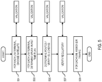
- FIG. 5 depicts an overview flow chart of an example algorithm by which the RRM function may determine the respective uplink burst plan and route tables for each UNI (serving both as an ingress point for uplink of data packets for transmission over the respective circuits serviced by the UNI, and as in egress point for downlink of data packets received from the respective circuits serviced by the UNI), in accordance with example embodiments of the present invention.
- the RRM function performs the process on a per UNI terminal basis, and with regard to each terminal, the process is performed for individual time intervals, where a particular route applies for only a respective time interval - e.g., 1 second.
- FIG. 1 e.g.
- a terminal can be moved to a different satellite for certain respective time intervals (where the terminal being moved may be the terminal of a current route being determined, of may be a terminal of a previously determined route), an alternate may be chosen for an intermediate hop in a circuit route for certain respective time intervals, etc.
- the RRM function chooses a first satellite as a tentative selection of the satellite to which the terminal will be assigned for a respective time interval.
- the satellite choice may be based on the terminal location and the satellite ephemeris (e.g., selecting the nearest available satellite).
- the RRM function performs a validation test considering for example, if a blockage exists (e.g., trees, buildings, etc.), if the satellite power budget does not support operation during the respective time interval, or if the equivalent power flux density (EPFD) from that satellite for its beam illuminating the respective UNI terminal exceeds a total EPFD limitation. If any validation fails, the RRM function may be required to choose an alternative satellite as the tentative selection of the satellite for the respective time interval. If the validation passes, then the selected satellite is tentatively set as the satellite to which the terminal will be associated for the respective time interval.
- a blockage e.g., trees, buildings, etc.
- EPFD equivalent power flux density
- the RRM function determines an uplink burst time plan.
- the RRM function must determine respective loading relative to the terminal and the satellite to ensure that each node will be capable of handling the overall load being assigned to it during each respective time interval.
- One factor relevant to this loading determination is the ingress and egress load of the terminal. The determination of the ingress and egress load for a given UNI terminal will initially be based on the total committed information rate (CIR) that the terminal is committed to provide for all circuits being serviced by the terminal during the respective time interval.
- CIR total committed information rate
- the determination of the ingress and egress load for the UNI terminal may also be based on real-time load reporting from the terminal and the respective satellite (e.g., the terminal can be configured to periodically report uplink traffic levels and queue status to the network manager or RRM function, and the respective satellite can report queue status or maximum wait time, or other congestion metrics for input to the uplink burst time planning).
- the RRM function estimates an anticipated modulation and coding (modcod) scheme that it estimates the terminal will be employing for the ingress and egress during the respective time interval -for example, according to propagation loss, power control and weather.
- the bandwidth of the respective link will depend on the modcod scheme that the terminal is able to employ in view of the link conditions with that satellite.
- the RRM function may also account for the route headers added to the data packets and protocol overhead in the determination of the ingress and egress load.
- another factor relevant to the loading determination is the total load of each tentatively chosen satellite for each respective time interval (e.g., considering the number of terminals communicating with the satellite from within that satellite beam (including gateways), and also the loads of the satellite ISL links, for the respective time interval). Accordingly, for each satellite, the RRM function determines its overall loading, which may be accomplished by summing the load over all ingress traffic into the satellite for each respective time interval.
- the RRM function may separately sum the load over all egress traffic to the terminals being serviced by the satellite downlink during each respective time interval, and may also separately sum the ingress/egress load over each ISL during each respective time interval and separately sum the ingress/egress load for all gateways associate with the satellite during each respective time interval.
- the RRM function sets the tentative satellite assignments as permanent assignments for association of the respective terminals with that satellite for each respective time interval, and for determination of the uplink burst time plan for each UNI terminal.
- the traffic may not be admitted, (ii) if during the one second interval, a second satellite could illuminate the (ingress or egress) cell of a terminal, that terminal may be moved to the second satellite (or all the terminals in the cell should move to the second satellite), (iii) move a cell that was going to switch to another satellite soon anyway, (iv) the situation can be marked as an issue and the moves can be performed in a second iteration.
- the RRM function then creates an uplink burst time plan for each UNI terminal that governs or sets the uplink burst times during which each such terminal will uplink the data packets of the respective circuits that the terminal is servicing.
- the uplink time plan is determined such that each terminal is addressed long enough to satisfy the respective service level requirements for the circuits serviced by the terminal.
- ground segment constraints such as EIRP and G/T, tracking speed, make before break, etc.
- the burst time plan should not significantly change from the terminal perspective (only the satellite receiving the uplink bursts will change), uplink timing changes to accommodate the different slant paths for different satellites.
- each UNI is assigned to a particular satellite and is assigned a respective burst time plan for uplink of the data packet for each circuit being serviced by the terminal.
- the RRM function determines the satellite-to-satellite ISL hops from the source UNI terminal to the destination UNI terminal, and builds the route table for the UNI terminal. As part of the route determinations, the RRM function verifies the respective inter-satellite link (ISL) loading. By way of example, with regard to ISL loading, the RRM function may verify that the respective ISLs have enough bandwidth to carry the traffic to the respective destinations.
- ISL inter-satellite link
- inter-constellation ISLs would be subject to interruption, where RRM planning would incorporate such interruptions into the routes.
- appropriately placed GWs could serve as pseudo-ISLs and route traffic when ISLs are overloaded, which could be part of RRM planning or employed on an ad hoc basis.
- the route table for each UNI provides a series of routes for each circuit serviced by the UNI, broken down by time intervals, where each route provides an end-to-end connection of links for the transmission of data packets over the circuit (from the source/ingress UNI, through certain ISLs between respective satellites of the constellation, to the destination/egress UNI) that is valid for the respective time interval.
- the route table provides the respective circuit route for the data packet for the time interval during which the packet will be transmitted by the UNI.
- the burst time plan provides the specific uplink bursts assigned to the UNI for uplink of the data packets of all circuits serviced by the UNI.
- the RRM function verifies that all applicable regulatory requirements are met.
- the RRM function may determine the EPFD for every hop, and based on the determined EPFDs, adjustments can be made to correct any violations. For example, changes can be made to the uplink burst time plan first without moving any terminals to different satellites, which might be done by conservatively assuming that all satellites use the same frequency and are on at the same time. Also, in the case of an EPFD violation, a less conservative calculation can be considered or a change can be implemented to the nearest usable satellite. Further, considering that EPFD is a combination of all satellites, this may need to be done many times.
- the RRM function considers assignment of excess information rate traffic (EIR) traffic.
- EIR excess information rate traffic
- additional traffic requirements may be assigned to a terminal to meet excess bandwidth requirements (e.g., bandwidth on demand, or excess information rate traffic) of a customer/subscriber.
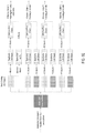
- FIGS. 6A-6E depict diagrams illustrating different downlink queueing approaches for the downlink of data packets to the destination UNI terminal, in accordance with example embodiments of the present invention.
- alternative examples for downlink hopping are provided.
- the side-lobe patterns will vary slightly as the satellite forming the beam moves within its constellation.
- controlled interference would be based on the specific details of the satellite phased array antennas, and changing side-lobe patterns will change interference levels.
- the terminal could have two antennas for a make before break, with consideration of how the make-before-break affects queueing.
- a more sophisticated queue service discipline may prioritize the cells that are leaving the satellite field of view (FOV).
- the algorithm may be executed at a time interval other than one second, based on the rate at which the plan may change, and granularity with respect to the validity of routes.
- another variable parameter would be how far in advance the time plan would be determined, where, for example, the further in advance, the less that weather can be accounted for and the more storage would be required at the terminal, and, the less in advance, the harder to distribute and manage, but more responsive to traffic and weather.
- satellite diversity may be employed to avoid weather and/or terminal blockages, to provide an alternative satellite with less rain on the slant path and the satellite can illuminate a cell without interference.
- Such satellite diversity requires knowledge of atmospheric conditions and some moderately quick ability to reconfigure routes.
- an alternative satellite with unobstructed line of sight could provide for a substitute, which could be determined one time at terminal install, but changing satellites for one terminal may require others to move.
- dynamic overlay may be created at a central site, or, if quicker changes are needed, among distributed processing sites throughout the network, which could be on the satellite steerable antennas or the phased array.
- a processor e.g., either central or distributed
- traffic information may be employed to more optimally assign excess hops. For example, traditional Bandwidth on Demand requests may be received and processed centrally, at nearby GWs, or on board the satellite. If the calculations could be done quickly enough, the system could respond to real-time requests, and collect and use queue status from the terminals.
- congestion management may be employed. Only ingress traffic flow can be controlled at the UNI, but one or more egress ports may exceed the downlink capability.
- congestion management data may be collected in a number of different manners.
- color queues can contain data (which, however, may not be in the best format), or maximum queue wait times or queue depth may be used, or explicit congestion notifications may be employed, or the egress terminal could report back delays or out of order packets.
- central or local GW processor collects, refines and summarizes distributes information as needed, such as, at least to all the terminals that talk to this cell, and maybe to all the terminals in system. Further, ingress terminals may exercise source flow control accordingly.
- cell layouts may be changed, as appropriate.
- cell sizes could be chosen at start of operation and not changed over life, which might mean reduced performance when beams are formed by a satellite at maximum distance, which may be acceptable at beginning of life.
- cell sizes could be smaller in northern latitudes due to closer satellite spacing, where non-uniform, but fixed, beam size would have some impact on interference, which might be a reasonable trade.
- reuse pattern probably need not be purely 4-color in the final system. Frequencies must comply with regulatory constraints, and the ultimate plan should be optimized based on system traffic models. For example, if the bulk of the traffic is star, the gateways may use a disproportionate amount of hops on a particular color, thereby starving a terminal.
- the next hop could be as little as 3-bits.
- two forwarding ISLs which may require a test that the transmit ISL is going to the intended satellite if the ISL switches between satellites,
- (iv) burst time plan could be fairly constant at the terminal,
- (v) current distribution mechanisms may be employed.
- route and address tables may be structured second by second or by duration of route, (ii) may include alternative routes for packets arriving near early/late gates, (iii) terminal addresses may or may not be made hierarchical, as cell sizes or shapes may change during life of the system.
- FIG. 7 illustrates a computer system upon which example embodiments according to the present invention can be implemented.
- the computer system 700 includes a bus 701 or other communication mechanism for communicating information, and a processor 703 coupled to the bus 701 for processing information.
- the computer system 700 also includes main memory 705, such as a random access memory (RAM) or other dynamic storage device, coupled to the bus 701 for storing information and instructions to be executed by the processor 703.
- Main memory 705 can also be used for storing temporary variables or other intermediate information during execution of instructions to be executed by the processor 703.
- the computer system 700 further includes a read only memory (ROM) 707 or other static storage device coupled to the bus 701 for storing static information and instructions for the processor 703.
- ROM read only memory
- a storage device 709 such as a magnetic disk or optical disk, is additionally coupled to the bus 701 for storing information and instructions.
- approaches in accordance with example embodiments are provided by the computer system 700 in response to the processor 703 executing an arrangement of instructions contained in main memory 705.
- Such instructions can be read into main memory 705 from another computer-readable medium, such as the storage device 709.
- Execution of the arrangement of instructions contained in main memory 705 causes the processor 703 to perform the process steps described herein.
- processors in a multi-processing arrangement may also be employed to execute the instructions contained in main memory 705.
- hard-wired circuitry is used in place of or in combination with software instructions to implement the embodiment of the present invention.
- embodiments of the present invention are not limited to any specific combination of hardware circuitry and software.
- the computer system 700 also includes a communication interface 717 coupled to bus 701.
- the communication interface 717 provides a two-way data communication coupling to a network link 719 connected to a local network 721.
- the communication interface 717 may be a digital subscriber line (DSL) card or modem, an integrated services digital network (ISDN) card, a cable modem, or a telephone modem to provide a data communication connection to a corresponding type of telephone line.
- communication interface 717 may be a local area network (LAN) card (e.g. for EthernetTM or an Asynchronous Transfer Mode (ATM) network) to provide a data communication connection to a compatible LAN.
- LAN local area network
- Wireless links can also be implemented.
- communication interface 717 sends and receives electrical, electromagnetic, or optical signals that carry digital data streams representing various types of information.
- the communication interface 717 for example, includes peripheral interface devices, such as a Universal Serial Bus (USB) interface, a PCMCIA (Personal Computer Memory Card International Association) interface, etc.
- USB Universal Serial Bus
- PCMCIA Personal Computer Memory Card International Association
- the network link 719 typically provides data communication through one or more networks to other data devices.
- the network link 719 provides a connection through local network 721 to a host computer 723, which has connectivity to a network 725 (e.g. a wide area network (WAN) or the global packet data communication network now commonly referred to as the "Internet") or to data equipment operated by service provider.
- the local network 721 and network 725 both use electrical, electromagnetic, or optical signals to convey information and instructions.
- the signals through the various networks and the signals on network link 719 and through communication interface 717, which communicate digital data with computer system 700, are example forms of carrier waves bearing the information and instructions.
- the computer system 700 sends messages and receives data, including program code, through the network(s), network link 719, and communication interface 717.
- a server (not shown) might transmit requested code belonging to an application program for implementing an embodiment of the present invention through the network 1025, local network 721 and communication interface 717.
- the processor 703 executes the transmitted code while being received and/or store the code in storage device 709, or other non-volatile storage for later execution. In this manner, computer system 700 obtains application code in the form of a carrier wave.
- Non-volatile media include, for example, optical or magnetic disks, such as storage device 709.
- Volatile media may include dynamic memory, such as main memory 705.
- Common forms of computer-readable media include, for example, a floppy disk, a flexible disk, hard disk, magnetic tape, any other magnetic medium, a CD ROM, CDRW, DVD, any other optical medium, RAM, PROM, and EPROM, FLASH EPROM, any other memory chip or cartridge, or any other medium from which a computer can read.
- the instructions for carrying out at least part of the present invention may initially be borne on a magnetic disk of a remote computer.
- the remote computer loads the instructions into main memory and sends the instructions over a telephone line using a modem.
- a modem of a local computer system receives the data on the telephone line and uses an infrared transmitter to convert the data to an infrared signal and transmit the infrared signal to a portable computing device, such as a personal digital assistance (PDA) and a laptop.
- PDA personal digital assistance
- An infrared detector on the portable computing device receives the information and instructions borne by the infrared signal and places the data on a bus.
- the bus conveys the data to main memory, from which a processor retrieves and executes the instructions.
- the instructions received by main memory may optionally be stored on storage device either before or after execution by processor.
- example embodiments of the present invention may provide for various implementations (e.g., including hardware, firmware and/or software components), and, unless stated otherwise, all functions are performed by a CPU or a processor executing computer executable program code stored in a non-transitory memory or computer-readable storage medium, the various components can be implemented in different configurations of hardware, firmware, software, and/or a combination thereof. Except as otherwise disclosed herein, the various components shown in outline or in block form in the figures are individually well known and their internal construction and operation are not critical either to the making or using of this invention or to a description of the best mode thereof.
Description
- The present invention relates to radio resource management and data packet routing for fixed data circuits in non-geostationary orbit (NGSO) wireless data communications systems, such as low earth orbit (LEO) satellite data communications systems.
- Conventional multi-beam communications satellites (e.g., spot beam satellites) and high altitude platforms (HAPs) are generally designed in a manner whereby a given geographic coverage area is serviced by a pattern of beams defined based on the geometry of the antenna elements (e.g., phased array elements) and the beam coefficients applied to the antenna. In such conventional designs, the satellite/HAP antennae generate a configuration of fixed beams radiated by the antennae, where the fixed beams are preconfigured on the satellite/HAP and sweep across the ground as the satellite/HAP moves though its orbit or flight pattern. A user terminal is thus served sequentially by the different beams as the fixed beams sweep across the geographic site or cell where the terminal is located. For example, in a typical low earth orbit (LEO) satellite system, the period of a satellite orbit is determined by the altitude of the orbit. For a satellite at about 1200 km altitude the orbital period is less than two hours. Further, in the case where the satellite employs narrow beams for high gain, the user terminal experiences a beam handover as often as every 10 to 20 seconds, where each handover requires a change in frequency and polarization on the part of the terminal, which has to be synchronized at the satellite. An example of a radio resource management function of a satellite communications network is described in document
US5826169A . - Further, for example, in an non-geostationary orbit (NGSO) satellite data communications system, such as a multi-satellite LEO system, in order to provide data communications services between two ground terminals situated a relatively large geographic distance from each other, the data packets for such communications must be routed from the source satellites servicing the cell within which the source terminal is located (for the duration of the data communications) to the respective destination satellites servicing the cell within which the destination terminal is located (for the duration of the data communications). As presented below, depending on the extent of the geographic diversity of the two terminals, such data communications will require differing levels of route complexity, potentially involving a number of satellites and a number of gateways, in order for the respective data packets to traverse a wide geographic distance between the source and destination terminals. The extent of the routing complexity would depend on the number of satellites and gateways required to transmit the packets of the data communications from the source terminal to the destination terminal.
- For example, assuming a relatively short distance and assuming that a single ground gateway terminal services both the source and destination satellites, the data communications may only require transferring the respective data packets from the source satellites to the destination satellites via two hops, through the ground gateway servicing the source and destination satellites, while they are servicing the respective source and destination terminals (as would be understood, in view of the transitory nature of a LEO satellite system, at different points in time a different source satellite will be servicing the source terminal and a different destination satellite will be servicing the destination terminal). Alternatively, assuming a relatively large distance between the source and destination terminals, the routing of the respective data communications packets may be required to traverse a combination of a number of satellites and a number of gateways in order to traverse such a wide geographic distance. For example, at a given point in time, the data packets may have to traverse a number of satellite-gateway-satellite hops to traverse the geographic distance. As such, in view of the transitory nature of such a system, in order to maintain a long-term or relatively permanent data communications circuit between two such terminals, the route processing overhead become significant, and also the multiple satellite-gateway hops introduce significant delay in the packet transmissions between the two terminal endpoints of the circuit.
- What is needed, therefore, are approaches for efficient radio resource management and routing functions to support long-term or relatively permanent data communications circuits between two geographically diverse endpoint terminals in a non-geostationary orbit (NGSO) wireless data communications system, such as a low earth orbit (LEO) satellite system.
- The present invention advantageously addresses the foregoing requirements and needs, as well as others, by providing a system and methods for efficient radio resource management and routing functions to support long-term or relatively permanent data communications circuits between two geographically diverse endpoint terminals in a non-geostationary orbit (NGSO) wireless data communications system, such as a low earth orbit (LEO) satellite system.
- In accordance with example embodiments, a method is provided for determining a plurality of routes for a committed bit rate data communications circuit between a source ground terminal and a destination ground terminal. The circuit is formed via a plurality of satellites, each traveling in a respective non-geostationary orbit around the Earth, and a total time during which the circuit is active is divided into a plurality of time intervals of equal duration. The determination of the plurality of routes comprises (i) selecting, for each time interval, an uplink satellite of the constellation to service the source ground terminal as an ingress node for the circuit, and (ii) determining, for each time interval, a series of inter-satellite links connecting the uplink satellite selected for the respective time interval to a downlink satellite of the constellation servicing the destination ground terminal during the respective time interval, wherein the series of inter-satellite links is determined so that it will be valid for connection of the circuit between the uplink ground terminal and the downlink ground terminal during the respective time interval. the duration of each interval of the plurality of time intervals is based on a time of validity, based on the traveling of the plurality of satellites in their respective orbits, for a one of the inter-satellite links of all of the plurality of routes that is of the shortest duration.
- In accordance with further example embodiments, a system for providing one or more committed bit rate data communications circuits, each between a respective source ground terminal and a respective destination ground terminal is provided. Each circuit is formed via a plurality of satellites, each traveling in a respective non-geostationary orbit around the Earth, and a total time during which the circuit is active is divided into a plurality of time intervals of equal duration. The determination of the plurality of routes comprises (i) selecting, for each time interval, an uplink satellite of the constellation to service the source ground terminal as an ingress node for the circuit, and (ii) determining, for each time interval, a series of inter-satellite links connecting the uplink satellite selected for the respective time interval to a downlink satellite of the constellation servicing the destination ground terminal during the respective time interval, wherein the series of inter-satellite links is determined so that it will be valid for connection of the circuit between the uplink ground terminal and the downlink ground terminal during the respective time interval. the duration of each interval of the plurality of time intervals is based on a time of validity, based on the traveling of the plurality of satellites in their respective orbits, for a one of the inter-satellite links of all of the plurality of routes that is of the shortest duration.
- According to further example embodiments, the antennae of each satellite may be configured to form communications beams to illuminate a fixed/stationary pattern of cells on the ground as the satellite travels through its orbit. According to one such embodiment, the satellite is configured to generate rapidly time varying beams, with different scan angles, beam shapes and directivities, in order to illuminate the respective fixed/stationary ground-based cell pattern. While the beam/footprint of a satellite moves across the surface of the Earth relative to the movement of the satellite, the cells remain stationary or fixed (each satellite antenna continually adjusts the relative cell pattern of its respective beam to maintain a fixed/stationary cell pattern on the surface of the Earth - as the satellite moves, the satellite will continually service the cells of that cell pattern that are within the footprint of the satellite antenna beam). By way of example, a phased array antenna is employed on satellite, and the satellite is configured to dynamically determine the appropriate beamforming coefficients or weights, over given time intervals, in order to generate time varying beam patterns that illuminate the respective stationary cells on the ground. Further, each such ground-based cell may be assigned a fixed frequency/polarization (F/P) pair. Accordingly, as the communications platform moves, it forms the communications beams to illuminate the respective stationary cell pattern, where each cell is assigned a respective F/P pair. As such, a ground terminal located within a given cell utilizes a constant F/P pair for the fixed cell within which it is located irrespective of the satellite that is servicing the cell.
- Still other aspects, features, and advantages of the present invention are readily apparent from the following detailed description, simply by illustrating a number of particular embodiments and implementations, including the best mode contemplated for carrying out the present invention. The present invention is also capable of other and different embodiments, and its several details can be modified in various obvious respects, all without departing from the spirit and scope of the present invention. Accordingly, the drawing and description are to be regarded as illustrative in nature, and not as restrictive.
- Example embodiments of the present invention are illustrated by way of example, and not by way of limitation, in the figures of the accompanying drawings, in which like reference numerals refer to similar elements, and in which:
-
FIG. 1A illustrates an example satellite communications system (e.g., a LEO satellite system) for employing radio resource management and routing approaches for fixed data circuits, in accordance with example embodiments of the present invention; -
FIG. 1B illustrates a diagram of one example where each satellite (e.g., as shown in the Figure for the satellite 101y2) employs a total of four inter-satellite links (ISLs) between itself and neighboring satellites, in accordance with example embodiments of the present invention; -
Fig. 2A illustrates a diagram of a point-to-point data communications connection or circuit between two edge terminals via an NGSO (e.g., LEO) satellite constellation, in accordance with example embodiments of the present invention; -
FIG. 2B illustrates diagram of a Metro Ethernet Forum (MEF) circuit framework via two separate NGSO (e.g., LEO) satellite constellations, in accordance with example embodiments of the present invention; -
FIG. 3A illustrates an example route for data communications from one end-user subscriber to another end-user subscriber, during a first period of time, via a fixed circuit between two UNIs, through an NGSO (e.g., a LEO) satellite constellation, in accordance with example embodiments of the present invention; -
FIG. 3B illustrates an example route for the data communications ofFIG. 3A , from the one end-user subscriber to the other end-user subscriber, during a second period of time, via the same fixed circuit between the two UNI terminals, in accordance with example embodiments of the present invention; -
FIG. 4 illustrates a diagram of the processing performed by a UNI terminal for input data packets received by that UNI and destined for uplink to various respective circuits of end-user subscribers serviced by that UNI, in accordance with example embodiments of the present invention; -
FIG. 5 depicts an overview flow chart of an example algorithm by which the RRM function may determine the respective uplink burst plan and route tables for each UNI terminal, in accordance with example embodiments of the present invention; -
FIGS. 6A-6E depict diagrams illustrating different downlink queueing approaches for the downlink of data packets to the destination UNI terminal, in accordance with example embodiments of the present invention; and -
FIG. 7 illustrates a computer system upon which example embodiments according to the present invention can be implemented. - Systems and methods for efficient radio resource management and routing functions to support long-term or relatively permanent data communications circuits between two geographically diverse endpoint terminals in a non-geostationary orbit (NGSO) wireless data communications system, such as a low earth orbit (LEO) satellite system, are described. The present invention is not intended to be limited based on the described embodiments, and various modifications will be readily apparent. It will be apparent that the invention may be practiced without the specific details of the following description and/or with equivalent arrangements. Additionally, well-known structures and devices may be shown in block diagram form in order to avoid unnecessarily obscuring the invention. Further, the specific applications discussed herein are provided only as representative examples, and the principles described herein may be applied to other embodiments and applications without departing from the general scope of the present invention.
- Further, as will be appreciated, a module or component (as referred to herein) may be composed of software component(s), which are stored in a memory or other computer-readable storage medium, and executed by one or more processors or CPUs of the respective devices. As will also be appreciated, however, a module may alternatively be composed of hardware component(s) or firmware component(s), or a combination of hardware, firmware and/or software components. Further, with respect to the various example embodiments described herein, while certain of the functions are described as being performed by certain components or modules (or combinations thereof), such descriptions are provided as examples and are thus not intended to be limiting. Accordingly, any such functions may be envisioned as being performed by other components or modules (or combinations thereof), without departing from the spirit and general scope of the present invention. Moreover, the methods, processes and approaches described herein may be processor-implemented using processing circuitry that may comprise one or more microprocessors, application specific integrated circuits (ASICs), field programmable gate arrays (FPGAs), or other devices operable to be configured or programmed to implement the systems and/or methods described herein. For implementation on such devices that are operable to execute software instructions, the flow diagrams and methods described herein may be implemented in processor instructions stored in a computer-readable medium, such as executable software stored in a computer memory store.
- Further, terminology referring to computer-readable media or computer media or the like as used herein refers to any medium that participates in providing instructions to the processor of a computer or processor module or component for execution. Such a medium may take many forms, including but not limited to non-transitory non-volatile media and volatile media. Non-volatile media include, for example, optical disk media, magnetic disk media or electrical disk media (e.g., solid state disk or SDD). Volatile media include dynamic memory, such random access memory or RAM. Common forms of computer-readable media include, for example, floppy or flexible disk, hard disk, magnetic tape, any other magnetic medium, CD ROM, CDRW, DVD, any other optical medium, random access memory (RAM), programmable read only memory (PROM), erasable PROM, flash EPROM, any other memory chip or cartridge, or any other medium from which a computer can read data.
-
FIG. 1A illustrates an example satellite communications system (e.g., a LEO satellite system) for employing routing approaches for fixed data circuits, in accordance with example embodiments of the present invention. While the following description of example embodiments of the present invention is in the context of a LEO satellite system, as would be appreciated, the aspects and concepts described herein would be applicable to any communications system employing one or more non-geosynchronous orbit (NGSO) airborne communications platforms that travel or move relative to the surface of the Earth (e.g., low earth orbit (LEO) satellite systems, medium earth orbit (MEO) satellite systems, and high altitude platform (HAP) based systems). - With reference to
FIG. 1A , thesatellite communications system 100 includes a plurality ofsatellites 101, which may hereinafter be referred to as a constellation. The satellites of the constellation travel around theEarth 103 in different orbital planes, such as the orbital planes a and b depicted inFIG. 1A . For example, the satellites 101a1, 101a2, 101a3 travel in the orbital plane a, and the satellites 101b1, 101b2, 101b3 travel in the orbital plane b (an orbital plane may also be referred to herein simply as a plane or orbit). By way of example, an orbital plane, the satellites may be distributed at relatively even distances apart so that the angular position between each adjacent pair of satellites is substantially uniform, and the orbital planes may be highly inclined relative to the equator to provide global coverage (e.g., the angle formed between the orbital plane and the equatorial plane is greater than 70 degrees). By way of further example, the orbital planes may also distributed in a substantially uniform manner. A satellite in accordance with example embodiments employs a multiple beam antenna (e.g., a phased array antenna) that illuminates a respective geographic region or footprint on the surface of the Earth, such as the regions 105a1, 105a2, 105a3, 105b2 of the satellites 101a1, 101a2, 101a3, 101b2, respectively. As the satellite moves through its orbit, the footprint/beam moves across the surface of the Earth relative to the movement of the satellite. - Each geographic region illuminated by a satellite antenna is further divided into spot beams or cells 107. Each spot beam or cell provides data communication services to the
respective ground terminals 111 located within that cell. Further, according to certain example embodiments, while the beam/footprint of a satellite moves across the surface of the Earth relative to the movement of the satellite, the cells remain stationary or fixed (each satellite antenna continually adjusts the relative cell pattern of its respective beam to maintain a uniform cell pattern on the surface of the Earth - as the satellite moves, the satellite will continually service the cells of that cell pattern that are within the footprint of the satellite antenna beam). More specifically, considering the satellite 101a1 (for example), as the satellite travels through its orbit, the satellite will service the cells 107a1 while those cells are within the footprint of the respective satellite antenna beam. Further, at a certain point in time, for example, the cell 107alx (within which theterminal 111a is located) will become positioned at the edge of the satellite beam 105a1, and the link margin for the services provided to the terminal 111a will diminish). By this point in time, however, the satellite 101a2 will have moved into a position where the cell 107alx is now within the footprint of its antenna beam, and that cell can be transitioned to the satellite 101a2 for the duration of time that the cell is within the footprint of that satellite (now labeled in the Figure as cell 107a2x). Accordingly, from the standpoint of the terminal 111a, it remains in the same cell (the same frequency and polarization), but the communications services for the cell are transitioned from satellite to satellite (in this case, from the satellite 101a1 to the satellite 101a2). In order that the service to the terminal 111a is not interrupted, a handoff or handover will be performed transferring the service for the terminal 111a from the cell 107alx of the satellite 101a1 two the cell 107a2x of the satellite 101a2 (effectively the same cell, but serviced by a new satellite). Further, each satellite also may employ one or more inter-satellite links (ISLs) providing for data communications between that satellite and neighboring satellite, such as theISL 121a between the satellites 101a2 and 101a3 and theISL 121b between the satellites 101a2 and 101b2. - With further regard to inter-satellite links,
FIG. 1B illustrates a diagram of one example where each satellite (e.g., as shown in the Figure for the satellite 101y2) employs a total of four inter-satellite links (ISLs) between itself and neighboring satellites, in accordance with example embodiments of the present invention. Further, while the ISLs are depicted as bidirectional in the Figure, any one (or all) of them may alternatively be unidirectional). As illustrated inFIG. 1B , at a particular point in time during the orbit of the various satellites in the constellation, for example, the satellite 101y2 (within the orbital plane y) has anactive ISL 151 with the satellite 101y3 directly behind it in the same orbital plane, has anactive ISL 153 with the satellite 101y1 directly ahead of it in the same orbital plane, has anactive ISL 155 with the satellite 101z1 in the orbital plane z directly to its left (from the perspective of the satellite 101y2 moving downwards in the orbital plane, as indicated by the arrow at the end of the dashed line reflecting the orbital plane y), and has anactive ISL 157 with the satellite 101x1 in the orbital plane x directly to its right (again, from the perspective of the satellite 101y2 moving downwards in its orbital plane). With further regard to the example ofFIG. 1B , as would be appreciated, within an orbital plane, because the satellites remain relatively uniform around the orbital plane, for any given satellite, the adjacent satellites ahead of and behind that satellite remain constant, and thus the ISLs between adjacent satellites within an orbital plane can remain constant. For the ISLs between satellites in adjacent parallel orbital planes, as would be recognized by one of ordinary skill in the art, depending on the positions of two adjacent satellites (at a given point in time) within their respective orbital planes and the respective locations of those orbital planes around the earth, the length of time that a given ISL between two such satellites will vary. For example, there will be times that two such satellites may be passing by each other at very rapid rates, and thus an ISL between those two satellites at that point in time will not be active for a long period of time (e.g., that ISL may only be valid for a period of time on the order of one to a few seconds) - whereas there will also be times that two such satellites may be able to support an ISL between them for a relatively longer period of time. Based on the configuration of the constellation and monitoring of satellite positioning based on ephemeris information that may be broadcast by the satellites of the constellation (in systems where the satellites broadcast their ephemeris information reflecting position and velocity vector information of the satellite), however, the network operations center of the system will have relatively accurate knowledge of the positions of each satellite within the constellation at all times. - In accordance with example embodiments of the present invention, the provided system and methods employ radio resource management and routing functions to provide long-term or relatively permanent data communications circuits between two geographically
diverse network terminals 111. According to one embodiment, the system comprises a constellation of NGSO satellites (e.g., LEO satellites, MEO satellites or a combination of LEO and MEO satellites) in at least one orbital plane operating in at least one altitude. According to a further embodiment, the system comprises a constellation of satellites configured with a plurality of NGSO satellites in each of multiple orbital planes, where the satellites are spaced around each orbital plane, and the multiple orbital planes are spaced at various inclinations around the earth, in order to provide global satellite coverage over the relative entire surface of the Earth. According to such embodiments, the system further comprises a network processing function (which could be centralized, distributed, or in the cloud) configured to determine and control the radio resource management in the routing functions of the network, and a plurality of user satellite terminals (UTs) configured to communicate with one another via data communications services provided by the satellite constellation and the network processing function. The data communications between the UTs are carried directly between the UTs via the satellite constellation (or via a combination of the satellite constellation and one or more intermediate gateways), based on a plurality of routing tables determined and provided by via an algorithm configured to address the continually changing routes among the constellation of satellites within the network. By way of example, a routing table comprises a list of routes, with each route having a valid period and each route consisting of a set of "next hops" to go from the source terminal to at least one destination terminal. The valid period, for example, might be expressed as a fixed duration of, say, one second, or as a start and end time, say 3:00PM to 3:11PM on a given date. Further, according to a further embodiment, the system may be configured to employ a fixed reuse pattern on the ground and a resource management function, which would significantly simplify capacity plan computations based on, for example, elimination of the need to compute interference. - According to such embodiments, the provided approaches facilitate the provision of a carrier-grade data communications service or circuit (e.g., a committed information rate circuit/service) between a UT or user network interface (UNI) and at least one other UT or UNI, where the "carrier-grade" implies a high availability, low latency, low error rate connection that remains continuous even as the satellites move and the respective packet data routes of the circuit continually change.
FIG. 2A illustrates a diagram of adata communications circuit 211 between a oneterminal 111a and afurther terminal 111b via the NGSO (e.g., LEO)satellite constellation 213, in accordance with example embodiments of the present invention. By way of example, theterminals circuit 211 may comprise a point to point Ethernet virtual circuit (EVC) through thesatellite constellation 213. Further, each UNI may be located at a very small aperture terminal (VSAT) or a gateway terminal (GW), or a UNI may alternatively be an additional network entirely. Accordingly, the service may comprise a UNI to UNI service or a UNI to external network-network interface (ENNI) service. Further, multiple satellites are in view at all times (e.g., with fully deployed satellite constellations), and inter-satellite links (ISLs) and Gateways move traffic between satellites as needed. - By way of example, one framework for providing such carrier-grade services or circuits is the metro Ethernet forum (MEF). The MEF is a nonprofit international industry consortium, composed of service providers, incumbent local exchange carriers, network equipment vendors, and other networking companies, that functions to facilitate the definition, design and adoption of carrier ethernet networks and services. As described at the MEF website (www.mef.net), "[t]he MEF is a California, USA registered 501c(3) industry association that is the enabling force for the development and implementation of agile, assured and orchestrated Third Network services for the digital economy and the hyper-connected world, where such "Third Network services are delivered over automated, virtualized, and interconnected networks globally powered by Carrier Ethernet 2.0 (CE 2.0), Lifecycle Service Orchestration (LSO), SDN, and NFV." The MEF describes standards for offering a service between an ingress and egress point. More detailed information about the MEF can be found at www.mef.net. By way of further example, other services may consist of cellular backhaul, or connection of other carrier MEF networks together.
FIG. 2B illustrates diagram of an MEF circuit framework via two separate NGSO (e.g., LEO)satellite constellations user subscribers 231, 233 accesses therespective UNI respective network interface carrier ethernet circuit 226 is provided between theUNI 221 and theENNI 225 via theconstellation 222, and acarrier ethernet circuit 228 is provided between theENNI 227 and theUNI 229 via theconstellation 224. TheENNIs network interface 223. Alternatively, a single constellation may provide the carrier ethernet circuits between two edge UNIs. In any configuration, however, the approaches provided in accordance with example embodiments of the present invention are applicable to each of the individual circuits between two respective UNIs. The particular protocol pursuant to which the circuit is provided, however, need not necessarily be the Ethernet protocol, but rather may take the form of any networking protocol or layer of protocols capable of facilitating such carrier grade circuits. To access the subscribed to circuits, an end-user subscriber site interfaces with the network via a respective protocol interface at an UNI configured or assigned to serve as an ingress/egress point for accessing the network from that end-user subscriber site. - With a traditional LEO satellite, the satellite antenna generates a fixed cell pattern within the antenna footprint, according to the antenna geometry and coefficients applied to the phased array antenna elements, within the antenna coordinate system - meaning that the cell pattern is fixed relative to the illumination of the beams at the satellite phased array antenna. As such, because the cell pattern is fixed relative to the antenna coordinate system, as the satellite travels in its orbit, the cell pattern moves across the face of the earth. Further, as the cell pattern moves across the face of the earth, the particular servicing a given terminal will change rapidly and the respective shape of each cell will vary relative to the angle of inclination of the satellite beam and the distance of the satellite from the earth (as the orbit of a satellite is not necessarily circular and is typically more elliptical in shape, and thus the angle of inclination of the satellite beam relative to the Earth and the distance of the satellite from the Earth changes throughout the orbital path). Accordingly, as mentioned above, with such a traditional LEO satellite, the frequency of handovers for a given terminal is relatively high. Alternatively, the satellite and satellite antenna may instead generate dynamically varying spot beams that illuminate a fixed cell pattern on the surface of the Earth, which remains stationary as the satellite travels over respective coverage areas on the surface of the Earth. With such an approach, the particular cell servicing a given terminal remains constant for a substantially longer period of time, and thus the frequency of handovers is significantly reduced.
- In accordance with example embodiments, therefore, a cell layout created by each satellite of a satellite system constellation may comprise a contiguous pattern of hexagonal cells covering a respective geographic region on the Earth's surface. In such a system, a fixed reuse pattern may be employed amongst the cells, where the reuse pattern satisfies requirements for mitigating interference between cells and satisfies all applicable regulatory rules (e.g., spectrum usage, maximum power flux density limitations, etc.) and other applicable rules/requirements. Further, in accordance with one approach, a nearly constant capacity density is provided across the cell patterns of each satellite footprint, which in turn could facilitate a committed information rate (CIR) service over a particular circuit throughout all periods of time that the circuit is operational, and such a service may be established anywhere within the system. Further, the pattern and capacity density allocation may remain relatively uniform throughout the system life, or the cell sizes and respective capacity density allocation may evolve as the satellite constellation matures over time (e.g., as the business matures, and demand increases, the cell patterns can be redefined over time to meet the maturing business requirements/demands. Further, the provided approaches accommodate the addition/deletion of customers and the addition/deletion of circuits for a given customer. For example, as new customers/subscribers come on board, or existing customers add additional circuits or increase bandwidth of existing circuits, the overall resource management and the routing tables for the existing circuits can be redefined to accommodate the added circuits and increased bandwidth (e.g., to accommodate modified load balancing to avoid overloading any nodes of the system during respective periods of time).
- In the following description, a process for constructing the static routing table from available information is described, wherein it is assumed that the table is generated from a central computer, or alternatively via a distributed computing architecture (e.g., a cloud-based architecture), and then distributed to the UTs and GWs. Further, variations may include storage in the satellite or generation in a more distributed fashion. In accordance with example embodiments of the present invention, while the approaches provided thereby may be applied to a system employing a constellation of satellites utilizing a fixed beam or cell pattern relative to the respective satellite antenna, the embodiments described herein address a system employing a constellation of satellites utilizing a fixed ground-based spot beam or cell pattern approach. As introduced above, such satellite antennae generate dynamically varying spot beams (relative to the plane of the satellite antenna or the satellite antenna coordinate system) that illuminate a fixed cell pattern on the surface of the Earth, which remains stationary as the satellite travels over respective coverage areas on the surface of the Earth.
- According to example embodiments, a service and routing function are provided, which facilitates the establishment and maintenance of fixed circuits between geographically diverse ground terminals, whereby (for a given circuit) the routing function determines and specifies a series of routes over time, where each route specifies a valid route between two respective terminal endpoints for a respective period of time. According to such embodiments, the radio resource management (RRM) function may create a quasi-static uplink capacity plan for the entire network, which is quasi-static from the perspective of the UNI (the ingress/egress GWs or UTs with which the customer is networked or interfaces for access to its assigned circuits). By way of example, the RRM function provides an uplink burst plan for each UNI of the network, which allocates a specific time plan for uplink bursts to each satellite with which the UNI will be communicating during a respective period of time. The operation of the uplink capacity planning and the uplink burst assignments to the UNIs of the network is discussed in further detail below. According to one such embodiment, the uplink traffic of a UT is at a steady rate independent of satellite positions. Additionally, according to a further such embodiment, the RRM may also accommodate some degree of variability on top of the plan, for example, supporting new terminals and some bandwidth on demand. Further, in accordance with certain embodiments, downlink traffic from any given satellite and the destination ground terminal may be dynamic without a plan, where distributed congestion management may be applied to minimize packet loss. The operation of the point and shoot downlink functionality of each of the satellites of the constellation is also discussed in further detail below.
- By way of example,
FIG. 3A illustrates an example route for data communications from one end-user subscriber 331 to another end-user subscriber 333, during a first period of time, via a fixed circuit between twoUNIs satellite constellation 100, in accordance with example embodiments of the present invention. Further,FIG. 3B illustrates an example route for the data communications ofFIG. 3B , from the one end-user subscriber 331 to the other end-user subscriber 333, during a second period of time, via the same fixed circuit between the twoUNIs FIGs. 3A and3B reflect data communications of an end-user subscriber from the end-user subscriber site one 331 (e.g., located in New York) to the site two 333 (e.g., located in London). The end-user subscriber site one interfaces with the network via theUNI 111a (e.g., via network facility such as a LAN or WAN) and the end-user subscriber site two interfaces with the network via theUNI 111b (e.g., also via network facility such as a LAN or WAN). For the circuit routes depicted inFIGs. 3A and3B , for example, the end-user subscriber may have contracted with the system operator or service provider for a permanent circuit (e.g., contracted for a particular contract period and guaranteed bandwidth or constant information rate between the New York andLondon sites 331, 333). Further, in an alternate example, the circuit between these two sites may have been contracted for operation only during business hours in New York (e.g., Monday through Friday, 9 to 5). In any event, for that circuit, each of the respective UNIs 111a, 111b must know the appropriate routes for data packets to traverse thesatellite constellation 100 between them at any given time during the operable period for the circuit. - Accordingly, each of the
UNIs user sites - With reference to
FIG. 3A , for example, as data packets arrive at theUNI 111a from the end-user subscriber site 331 for transmission to the end-user site 333 during the first period of time, theUNI 111a will apply the respective route from the route table corresponding to that circuit that is valid for the first period of time. For that route, the route table will list the satellite 101a1 as the first-hop destination, the satellite 101b1 as the second-hop destination, the satellite 101b2 as the third-hop destination, the satellite 101c2 as the fourth-hop destination, the satellite 101c1 as the fifth-hop destination, and theUNI 111b as the sixth-hop destination. For each hop destination, the route table will include an appropriate address or other indicator identifying the respective destination satellite or terminal node. For each such packet, theUNI 111a will append a header to the packet indicating the series of hops for the route, and will then transfer the packet with the route header to the satellite 101a1 as the first-hop destination. The route header will identify the next hop destination to the satellite 101a1. Upon receipt of the packet, the satellite 101a1 will decode the header to determine the next hop destination (the second-hop destination - the satellite 101b1), will modify the route header in a manner to identify the next hop destination from the satellite 101b1 (the third-hop destination - the satellite 101b2), and will transmit the packet (with the modified header) to the satellite 101b1. Upon receipt of the packet, the satellite 101b1 similarly will decode the header to determine the next hop destination (the third-hop destination -the satellite 101b2), will modify the route header in a manner to identify the next hop destination from the satellite 101b2 (the fourth-hop destination - the satellite 101c2), and will transmit the packet (with the modified header) to the satellite 101b2. This progression of the packet will continue until it reaches the satellite 101c1, which will decode the header to determine the next hop destination as theUNI 111b, and will download the packet to theUNI 111b. TheUNI 111b will then transmit the packet to the end-user subscriber site 333 based on an ultimate destination address (e.g., a destination IP address). According to one embodiment, for each hop, the respective satellite may strip (or otherwise nullify) the header information relative to the route hop to the next satellite in the route so that (as received by that next satellite) the next hop route destination will effectively be the first hop destination relative to that next satellite in the route - the next satellite of the route does not need the header information based on which the packet arrived at that satellite, but rather only needs the information for the next hop destination from that satellite. Next hop routing is well understood in the industry. - With reference to
FIG. 3B , as data packets subsequently arrive at theUNI 111a from the end-user subscriber site 331 for transmission to the end-user site 333 during the second period of time, theUNI 111a will then apply the respective route from the route table corresponding to that circuit that is valid for the second period of time. For that route, the route table will list the satellite 101a1 as the first-hop destination, the satellite 101b2 as the second-hop destination, the satellite 101c3 as the third-hop destination, and theUNI 111b as the fourth-hop destination. In this example, during the second period of time, the ISLs between the respective satellites to complete the circuit have changed, and thus the route for that period of time will traverse a different series of satellites, as indicated by the route entry for that circuit during the second period of time. Further, with reference again toFIG. 3A , while there is an ISL (shown in a dashed line) between the satellites 101b1 and 101c1, this link may not have been chosen for that circuit route during the first period of time for one or more of a number of particular reasons. For example, that particular ISL may not have been chosen for that period of time because of a determined potential overload of the ISL at that time. Further, each route stored in a route table, for example the route for the time period t=0, is determined such that the designated path from the source UNI to the destination UNI is valid from the beginning of the time period at t=0 to the beginning of the time period at t=1. Various factors considered in determining the particular routes for any given period of time are discussed in further detail below. - By way of example, the following table reflects a route table that would be stored at the
UNI 111a for all routes, during all applicable time periods, for a circuit to theUNI 111b (t=1 corresponds to the first period of time for the route depicted inFIG. 3A , and t=2 corresponds to the second period of time for the route depicted inFIG. 3B (as would be appreciated, the structure of the route tables and the entries for the respective routes may take on any of a myriad of different forms without departing from the concepts of the embodiments of the present invention):TIME ROUTES TO UNI 111bt=1 101a1; 101b1; 101b2; 101c2; 101c1, UNI 111bt=2 101a1; 101b2; 101c3; UNI 111bt=3 hop 1;hop 2; ... ; hop nt=4 etc. - Similarly, by way of further example, the following table reflects a route table that would be stored at the
UNI 111b for all routes, during all applicable time periods, for the same circuit in the other direction to theUNI 111a.TIME ROUTES TO UNI 111bt=1 hop 1;hop 2; ... ; hop nt=2 hop 1;hop 2; ... ; hop nt=3 hop 1;hop 2; ... ; hop nt=4 etc. - According to such embodiments, therefore, each UNI serving as an ingress point to the satellite constellation will be provided with, and store within its memory, respective routing table for each circuit defined between it and a further UNI serving as an egress point from the satellite constellation. Further, the routes stored in a routing table for a particular circuit between two UNIs (one UNI serving as an ingress point to the satellite constellation and a second UNI serving as an egress point from the satellite constellation) will continually change over time as the satellites servicing the respective UNIs change and as the ISLs between the satellites of the constellation change. Additionally, in accordance with further example embodiments, each UNI will be provided with, and store within its memory, an uplink burst time plan providing timing/synchronization information as to when to transmit the data packets of the circuits serviced by the UNI. Further, according to example embodiments, each UNI can synchronize with a given satellites servicing that UNI at any given point in time based on any known synchronization method, such as synchronization based on ephemeris information provided by the satellites.
- According to yet further example embodiments, within any route, a gateway may serve as an intermediate node or hop destination within the route. By way of example, at a particular satellite hop node within a route, the next route may be specified as a downlink to a gateway in communication with the satellite during the respective period of time for that route. In the same manner as described above for the route, the satellite would modify the header route information for the data packet to specify the next hop from the gateway as, for example, a next satellite hop destination in the route, and would downlink the packet (with the modified header) to that gateway hop destination. Upon receipt of the data packet, the gateway would similarly modify the header route information for the packet and transmit the packet (with the modified header) to the next satellite hop destination, whereby the header would identify and appropriate further satellite hop or a downlink to the destination UNI (in the event that the satellite was the last satellite/hop of the route) as the next hop.
- With regard to uplink burst scheduling for the respective UNIs of the system (in the UNI's capacity as an ingress point to the network), according to example embodiments, as introduced above, the RRM function provides an uplink burst plan for each UNI of the network, which allocates a specific time plan for uplink bursts to each satellite with which the UNI will be communicating during a respective period of time. By way of example, the uplink burst scheduling for a particular UNI (in its capacity as an ingress UNI for various circuits of various respective end-users subscribers) will largely be based on the service level agreement commitments to each of the respective end-users subscribers for each of the circuits contracted for by that end user subscriber. In that regard, for a given customer circuit serviced by a particular UNI, the uplink burst time plan for that UNI will include the required assignment of uplink bursts to satisfy the bandwidth/information-rate as contracted for by the customer. Further, as would be appreciated by one of skill in the art, the overall uplink burst scheduling for the system would also be orchestrated to accommodate for various system factors, including the satellite availability for each UNI satellite terminal of the system at any given point in time, and the current load of each satellite available to each such UNI at a given point in time (including the overall load of the satellite beam within which the UNI is located and the current load of each of the ISLs of that satellite) in order to avoid congestion and overloading of any given satellite transmission channel or link. Additionally, other such factors may include the quality of the link of each satellite available to each such UNI at a given point in time and required circuit information rates for the respective circuits being serviced by that UNI, and potential downlink congestion of a particular satellite and other issues such as satellite downlink queue overflows or head of line blockage, etc. Additionally, as would be appreciated by one of ordinary skill in the art, various other system factors may impact the uplink burst scheduling for each UNI in the network. With further regard to the uplink bursts schedule for the system, that schedule will change over time to accommodate additional circuits of existing or new end-user subscribers and the termination of existing circuits as the system demand evolves.
- According to one such embodiment,
FIG. 4 illustrates a diagram of the processing performed by a UNI satellite terminal for input data packets received by that UNI and destined for uplink to various respective circuits of end-user subscribers serviced by that UNI, in accordance with example embodiments of the present invention. With reference toFIG. 3 , the end-user subscribers 431a to 431n interface with theUNI 111 for transmission of data packets via the circuits A to X serviced by theUNI 111. The data packets input to theUNI 111 from the respective end-user subscribers are received by the inputdata packet processor 401. The input data packet processor processes the received packets, and based on header information of each packet, the input data packet processor determines which particular circuit the packet is destined for (one of the circuits CIRCUIT A, ..., CIRCUIT X) and determines a respective priority level for the packet within a range of priority levels of data packets for the respective circuit. Based on the determined circuit and respective priority level, the input data packet processor forwards each packet to a respective queue for packets of that circuit and priority level combination. For example, as depicted in the Figure, there are n priority levels for each of the circuits A-X, an each packet of the CIRCUIT is forwarded to a respective queue based on its determine priority level (one of the queues A1, A2, ..., An), and similarly for each of the other circuits. - The
transmission processor 405 controls the dequeueing of the data packets from the respective queues and the processing of the data packets for transmission, and once processed for transmission, the transmission processor transmits the packets via theUNI antenna 311 for uplink to a respective satellite. By way of example, thetransmission processor 405 dequeues the packets from the respective queues based on circuit priority and packet priority within that circuit. Further, the transmission processor may also take other factors into account when dequeueing the packets, such as congestion control and avoidance of queue overflows. As each data packet is dequeued, thetransmission processor 405 processes the packet for transmission and transmits the data packet via the next available uplink burst (as scheduled by the uplink burst time plan for the UNI 111) in the order that the packets are dequeued. According to an alternative embodiment, each data packet may simply be process based only on the respective circuit over which that packet is to be transmitted. In that case, each circuit will have only one queue, and the packets will be dequeued from the respective queues based on priorities between the respective circuits. As will be further appreciated, various alternative methods for processing cueing and transmitting packets may be implemented without departing from the scope of example embodiments of the present invention. - With regard to the downlink of data packets by a respective last hop satellite of a circuit to the destination egress UNI satellite terminal, according to one example embodiment, the downlink is performed in a point and shoot manner as each packet is processed and ready for downlink by the respective satellite. By way of example, as such a satellite processes each data packet for downlink transmission to the destination egress UNI, the satellite simply transmits the packet within the next available time slot of the downlink spot beam for the cell within which that UNI is located. By way of further example, as with the cell pattern of the uplink beam of a given satellite, the downlink cell pattern may also be of a fixed nature, for example, with respect to frequency reuse in order to satisfy requirements for mitigating interference between cells and to satisfy applicable regulatory rules.
- In the context of example embodiments of the present invention, certain underlying principles are employed. By way of example, terrestrial RRM minimizes the satellite requirements and creates a cleaner functional break, which significantly reduces system roll-out and testing time. By way of further example, there is a tradeoff between satellite constellation complexity and the level of dynamic functionality employed, where mission demands may justify or require at least some dynamic assignment. The balance between constellation complexity and dynamic functions, however, may change over system life, but a minimal risk approach may be employed for launch of the system. Moreover, service demands may justify or require a dynamic downlink, where data rate may be controlled at the ingress UNI, but it does not dictate the data rate of the egress UNI. Even a static ingress can produce highly variable egress. Further, point and shoot may be ideal for this. Further, point and shoot, combined with adjacent cells being served by different satellites, may dictate a fixed cellular reuse pattern.
- In the context of the example embodiments of the present invention, errors may occur in data packet timing, for example, whereby a data packet may arrive at a respective satellite hop either early or late such that the respective next hop route is no longer or is not yet available. Such early and late arrivals may occur under a variety of different scenarios. In one scenario, uplink timing may be in error, for example, whereby (i) the uplink UNI terminal processes the data packet based on an anticipated delay in its queueing structure (for an anticipated transmission time) in inserts the route information for that anticipated transmission time, and (ii) if in operation the packet dequeues early or late, the packet may arrive at a satellite node within the route early or late such that the ISL to the next satellite hop may no longer be available or the uplink to the first hop satellite may no longer be available. In a further scenario, the ISL timing may be in error, for example, a data packet may traverse up to as many as nine ISL hops to get to the last hop satellite, and even though the ISLs would generally be designed for very low queueing delay, packets can arrive early or late for a particular ISL transmission. Further, such cases also apply where a downlink to a gateway substitutes for an ISL hop to a next satellite. As your further scenario, the downlink timing may be in error, for example, similar to the scenario of an error in uplink timing, whereby (i) a data packet may arrive early or late at the last satellite hop of a route such that the destination egress UNI is not yet or is no longer available to the last hop satellite-such a scenario might occur based on the packet having to traverse several queues with statistically varying loading. Accordingly, various random processes inherent in the radio resource management and routing functions of embodiments of the present invention may lead to inevitable early/late data packet timing events.
- In view of such potential timing errors, according to further example embodiments, early arrival may be mitigated by different procedures. According to one such embodiment for mitigating early packet arrival, data packets that arrive at a given node early may be dropped by that node. In that scenario, it may be up to the underlying transmission protocols, or the respective applications under which the data packet serve, to address the issue of dropped packets (e.g., by requesting retransmission). The solution of dropping the packets, however, may adversely affect packet loss rate objectives/requirements to the point where such objectives/requirements are no longer met. According to a further embodiment for mitigating early packet arrival, such early data packets may be rerouted. Such rerouting, for example, may be facilitated by (i) the source terminal or ingress UNI being configured to provide an alternative route for packets regarding which the terminal knows are likely to be transmitted near a timing boundary, (ii) the source terminal being configured to replicate packets known to arrive near timing boundaries, (iii) the satellite replicating packets regarding which the terminal knows are likely to be transmitted near a timing boundary (e.g., same data, but different labels), (iv) the node at which the packet arrives late being configured to downlink the late packet to a gateway for forwarding via a new route. According to yet a further embodiment for mitigating early packet arrival, the satellite node may be configured to save any such early packets for transmission via an ISL or downlink to a downlink cell that subsequently becomes available.
- In further view of such potential timing errors, according to other example embodiments, late arrival may be mitigated by different procedures. According to one such embodiment for mitigating late packet arrival, as in the case of an early packet arrival, data packets that arrive at a given node late may also be dropped by that node. Here also, the solution of dropping the packets, however, may adversely affect packet loss rate objectives/requirements to the point where such objectives/requirements are no longer met. According to a further embodiment for mitigating late packet arrival, data packets arriving at a given network node late may be serviced via make-before-break process, where two satellites illuminate the same beam without interference (which may be accomplished, for example, by splitting the band). According to yet a further embodiment for mitigating late packet arrival, here again, the system may be configured to reroute any late arriving data packets via any of the methods described above for rerouting early packets.
- With regard to the uplink burst planning and the route planning for the overall system, in accordance with example embodiments, the radio resource management (RRM) function and route planning may be centrally deployed at a network operations center or central network management site of the system. Alternatively, the RRM and route planning function may be distributed as a cloud computing system or distributed amongst various sites of the overall system. As would be appreciated, various factors impact or influence the actual implementation of this central processing function, such as scalability, backup options, geographic resources, the distribution of different business centers involved in the overall network operations, etc. irrespective of the actual implementation, however, by way of example, taking into account the overall configuration of all of the required circuits for the network, along with the various system factors that would impact the actual route for each respective circuit at each given point in time, the RRM route planning function generates the respective route table for each such circuit over the overall applicable time period during which the circuit must be operational. By way of further example, the series of routes for a particular circuit may be cyclical in time, for example, based on the cyclical nature of the orbits of the various satellites within the constellation, and specifically the satellites that may be involved in the routes between the two UNI endpoints of the circuit - as such, a series of routes in a route table for a given circuit may simply cycle throughout the overall time period for the circuit.
-
FIG. 5 depicts an overview flow chart of an example algorithm by which the RRM function may determine the respective uplink burst plan and route tables for each UNI (serving both as an ingress point for uplink of data packets for transmission over the respective circuits serviced by the UNI, and as in egress point for downlink of data packets received from the respective circuits serviced by the UNI), in accordance with example embodiments of the present invention. According to the algorithm, the RRM function performs the process on a per UNI terminal basis, and with regard to each terminal, the process is performed for individual time intervals, where a particular route applies for only a respective time interval - e.g., 1 second. Further,FIG. 5 depicts a validation function for each algorithm step - whereby, for each step loading, regulatory and other factors are verified with respect to the determinations made as part of the operation of the step, and when any particular validation fails, adjustments are made to alleviate the validation failure - for example, a terminal can be moved to a different satellite for certain respective time intervals (where the terminal being moved may be the terminal of a current route being determined, of may be a terminal of a previously determined route), an alternate may be chosen for an intermediate hop in a circuit route for certain respective time intervals, etc. - At
Step 501, for each UNI terminal, the RRM function chooses a first satellite as a tentative selection of the satellite to which the terminal will be assigned for a respective time interval. By way of example, the satellite choice may be based on the terminal location and the satellite ephemeris (e.g., selecting the nearest available satellite). Then, the RRM function performs a validation test considering for example, if a blockage exists (e.g., trees, buildings, etc.), if the satellite power budget does not support operation during the respective time interval, or if the equivalent power flux density (EPFD) from that satellite for its beam illuminating the respective UNI terminal exceeds a total EPFD limitation. If any validation fails, the RRM function may be required to choose an alternative satellite as the tentative selection of the satellite for the respective time interval. If the validation passes, then the selected satellite is tentatively set as the satellite to which the terminal will be associated for the respective time interval. - Once the a tentative satellite selection is made for each UNI terminal, at
Step 503, for each UNI terminal, the RRM function then determines an uplink burst time plan. By way of example, as part of the determination of the uplink burst plan, the RRM function must determine respective loading relative to the terminal and the satellite to ensure that each node will be capable of handling the overall load being assigned to it during each respective time interval. One factor relevant to this loading determination is the ingress and egress load of the terminal. The determination of the ingress and egress load for a given UNI terminal will initially be based on the total committed information rate (CIR) that the terminal is committed to provide for all circuits being serviced by the terminal during the respective time interval. Further, the determination of the ingress and egress load for the UNI terminal may also be based on real-time load reporting from the terminal and the respective satellite (e.g., the terminal can be configured to periodically report uplink traffic levels and queue status to the network manager or RRM function, and the respective satellite can report queue status or maximum wait time, or other congestion metrics for input to the uplink burst time planning). Further, as part of the determination of the ingress and egress load for the terminal, the RRM function estimates an anticipated modulation and coding (modcod) scheme that it estimates the terminal will be employing for the ingress and egress during the respective time interval -for example, according to propagation loss, power control and weather. This may be necessary because, based on the choice of satellite for the given time interval, the bandwidth of the respective link will depend on the modcod scheme that the terminal is able to employ in view of the link conditions with that satellite. Further, the RRM function may also account for the route headers added to the data packets and protocol overhead in the determination of the ingress and egress load. - By way of further example, another factor relevant to the loading determination is the total load of each tentatively chosen satellite for each respective time interval (e.g., considering the number of terminals communicating with the satellite from within that satellite beam (including gateways), and also the loads of the satellite ISL links, for the respective time interval). Accordingly, for each satellite, the RRM function determines its overall loading, which may be accomplished by summing the load over all ingress traffic into the satellite for each respective time interval. Further, to ensure that any given satellite link isn't overloaded, the RRM function may separately sum the load over all egress traffic to the terminals being serviced by the satellite downlink during each respective time interval, and may also separately sum the ingress/egress load over each ISL during each respective time interval and separately sum the ingress/egress load for all gateways associate with the satellite during each respective time interval.
- Once all such loading determinations are validated as being operable (on the foregoing per-UNI terminal and per-satellite bases), the RRM function then sets the tentative satellite assignments as permanent assignments for association of the respective terminals with that satellite for each respective time interval, and for determination of the uplink burst time plan for each UNI terminal. However, if the total determined load is above a predetermined threshold, then one of several alternative options may be chosen - (i) the traffic may not be admitted, (ii) if during the one second interval, a second satellite could illuminate the (ingress or egress) cell of a terminal, that terminal may be moved to the second satellite (or all the terminals in the cell should move to the second satellite), (iii) move a cell that was going to switch to another satellite soon anyway, (iv) the situation can be marked as an issue and the moves can be performed in a second iteration.
- For each satellite, the RRM function then creates an uplink burst time plan for each UNI terminal that governs or sets the uplink burst times during which each such terminal will uplink the data packets of the respective circuits that the terminal is servicing. By way of example, the uplink time plan is determined such that each terminal is addressed long enough to satisfy the respective service level requirements for the circuits serviced by the terminal. Further, other factors may be considered in the determination of the uplink time plan, such as ground segment constraints (such as EIRP and G/T, tracking speed, make before break, etc.), the burst time plan should not significantly change from the terminal perspective (only the satellite receiving the uplink bursts will change), uplink timing changes to accommodate the different slant paths for different satellites.
- At this point, for each respective time interval, each UNI is assigned to a particular satellite and is assigned a respective burst time plan for uplink of the data packet for each circuit being serviced by the terminal.
- At
Step 505, for each UNI terminal (in its capacity as the ingress point or source terminal for the circuits being serviced by the terminal), for each circuit, during each respective time interval for the circuit, the RRM function determines the satellite-to-satellite ISL hops from the source UNI terminal to the destination UNI terminal, and builds the route table for the UNI terminal. As part of the route determinations, the RRM function verifies the respective inter-satellite link (ISL) loading. By way of example, with regard to ISL loading, the RRM function may verify that the respective ISLs have enough bandwidth to carry the traffic to the respective destinations. According to an alternate example with regard to ISL loading, if provided, inter-constellation ISLs would be subject to interruption, where RRM planning would incorporate such interruptions into the routes. By way of further example, appropriately placed GWs could serve as pseudo-ISLs and route traffic when ISLs are overloaded, which could be part of RRM planning or employed on an ad hoc basis. As described above, the route table for each UNI provides a series of routes for each circuit serviced by the UNI, broken down by time intervals, where each route provides an end-to-end connection of links for the transmission of data packets over the circuit (from the source/ingress UNI, through certain ISLs between respective satellites of the constellation, to the destination/egress UNI) that is valid for the respective time interval. Thereby, for each data packet received by the UNI, the route table provides the respective circuit route for the data packet for the time interval during which the packet will be transmitted by the UNI. Further, the burst time plan provides the specific uplink bursts assigned to the UNI for uplink of the data packets of all circuits serviced by the UNI. - At
Step 507, the RRM function verifies that all applicable regulatory requirements are met. By way of example, with regard to regulatory verification, after all burst time plans have been determined, the RRM function may determine the EPFD for every hop, and based on the determined EPFDs, adjustments can be made to correct any violations. For example, changes can be made to the uplink burst time plan first without moving any terminals to different satellites, which might be done by conservatively assuming that all satellites use the same frequency and are on at the same time. Also, in the case of an EPFD violation, a less conservative calculation can be considered or a change can be implemented to the nearest usable satellite. Further, considering that EPFD is a combination of all satellites, this may need to be done many times. - Further, at
Step 509, for each UNI terminal, the RRM function considers assignment of excess information rate traffic (EIR) traffic. At this point, based on the the determination of the ingress and egress load for the UNI terminal, additional traffic requirements may be assigned to a terminal to meet excess bandwidth requirements (e.g., bandwidth on demand, or excess information rate traffic) of a customer/subscriber. - According to example embodiments,
FIGS. 6A-6E depict diagrams illustrating different downlink queueing approaches for the downlink of data packets to the destination UNI terminal, in accordance with example embodiments of the present invention. - According to further embodiments, alternative examples for downlink hopping are provided. By way of example, even with stationary cells of a fixed cell size and reuse plan, the side-lobe patterns will vary slightly as the satellite forming the beam moves within its constellation. In this context, controlled interference would be based on the specific details of the satellite phased array antennas, and changing side-lobe patterns will change interference levels. Such may be dealt with based on system planning, or may be dealt with in real-time by the RRM. Further, the terminal could have two antennas for a make before break, with consideration of how the make-before-break affects queueing. A more sophisticated queue service discipline may prioritize the cells that are leaving the satellite field of view (FOV).
- According to further example embodiments, the algorithm may be executed at a time interval other than one second, based on the rate at which the plan may change, and granularity with respect to the validity of routes. Further, another variable parameter would be how far in advance the time plan would be determined, where, for example, the further in advance, the less that weather can be accounted for and the more storage would be required at the terminal, and, the less in advance, the harder to distribute and manage, but more responsive to traffic and weather.
- According to further example embodiments, satellite diversity may be employed to avoid weather and/or terminal blockages, to provide an alternative satellite with less rain on the slant path and the satellite can illuminate a cell without interference. Such satellite diversity, however, requires knowledge of atmospheric conditions and some moderately quick ability to reconfigure routes. Further, an alternative satellite with unobstructed line of sight could provide for a substitute, which could be determined one time at terminal install, but changing satellites for one terminal may require others to move.
- According to further example embodiments, dynamic overlay may be created at a central site, or, if quicker changes are needed, among distributed processing sites throughout the network, which could be on the satellite steerable antennas or the phased array.
- According to further example embodiments, with regard to handling of dynamic uplink traffic, ability to accommodate UNI add/modify/delete, changes to service level requirements, new customers, time of day load variation, etc. would be implemented. Further, if excess hops are available, they could be distributed among terminal community to preempt demand, which should not create interference or EPFD violations. Additionally, a processor (e.g., either central or distributed) may be employed to use traffic information to more optimally assign excess hops. For example, traditional Bandwidth on Demand requests may be received and processed centrally, at nearby GWs, or on board the satellite. If the calculations could be done quickly enough, the system could respond to real-time requests, and collect and use queue status from the terminals.
- According to further example embodiments, congestion management may be employed. Only ingress traffic flow can be controlled at the UNI, but one or more egress ports may exceed the downlink capability. In that context, congestion management data may be collected in a number of different manners. By way of example, color queues can contain data (which, however, may not be in the best format), or maximum queue wait times or queue depth may be used, or explicit congestion notifications may be employed, or the egress terminal could report back delays or out of order packets. Further, central or local GW processor collects, refines and summarizes distributes information as needed, such as, at least to all the terminals that talk to this cell, and maybe to all the terminals in system. Further, ingress terminals may exercise source flow control accordingly.
- According to further example embodiments, cell layouts may be changed, as appropriate. By way of example, cell sizes could be chosen at start of operation and not changed over life, which might mean reduced performance when beams are formed by a satellite at maximum distance, which may be acceptable at beginning of life. Further, cell sizes could be smaller in northern latitudes due to closer satellite spacing, where non-uniform, but fixed, beam size would have some impact on interference, which might be a reasonable trade. Further, reuse pattern probably need not be purely 4-color in the final system. Frequencies must comply with regulatory constraints, and the ultimate plan should be optimized based on system traffic models. For example, if the bulk of the traffic is star, the gateways may use a disproportionate amount of hops on a particular color, thereby starving a terminal.
- According to further example embodiments, with regard to plan distribution, the next hop could be as little as 3-bits. For example, (i) two forwarding ISLs, which may require a test that the transmit ISL is going to the intended satellite if the ISL switches between satellites, (ii) stay on egress satellite and forward to burst assembler, (iii) go to on-board processor, (iv) burst time plan could be fairly constant at the terminal, (v) current distribution mechanisms may be employed.
- According to further example embodiments, route and address tables (i) may be structured second by second or by duration of route, (ii) may include alternative routes for packets arriving near early/late gates, (iii) terminal addresses may or may not be made hierarchical, as cell sizes or shapes may change during life of the system.
-
FIG. 7 illustrates a computer system upon which example embodiments according to the present invention can be implemented. Thecomputer system 700 includes a bus 701 or other communication mechanism for communicating information, and aprocessor 703 coupled to the bus 701 for processing information. Thecomputer system 700 also includesmain memory 705, such as a random access memory (RAM) or other dynamic storage device, coupled to the bus 701 for storing information and instructions to be executed by theprocessor 703.Main memory 705 can also be used for storing temporary variables or other intermediate information during execution of instructions to be executed by theprocessor 703. Thecomputer system 700 further includes a read only memory (ROM) 707 or other static storage device coupled to the bus 701 for storing static information and instructions for theprocessor 703. Astorage device 709, such as a magnetic disk or optical disk, is additionally coupled to the bus 701 for storing information and instructions. - According to one embodiment of the invention, approaches in accordance with example embodiments are provided by the
computer system 700 in response to theprocessor 703 executing an arrangement of instructions contained inmain memory 705. Such instructions can be read intomain memory 705 from another computer-readable medium, such as thestorage device 709. Execution of the arrangement of instructions contained inmain memory 705 causes theprocessor 703 to perform the process steps described herein. One or more processors in a multi-processing arrangement may also be employed to execute the instructions contained inmain memory 705. In alternative embodiments, hard-wired circuitry is used in place of or in combination with software instructions to implement the embodiment of the present invention. Thus, embodiments of the present invention are not limited to any specific combination of hardware circuitry and software. - The
computer system 700 also includes acommunication interface 717 coupled to bus 701. Thecommunication interface 717 provides a two-way data communication coupling to anetwork link 719 connected to alocal network 721. For example, thecommunication interface 717 may be a digital subscriber line (DSL) card or modem, an integrated services digital network (ISDN) card, a cable modem, or a telephone modem to provide a data communication connection to a corresponding type of telephone line. As another example,communication interface 717 may be a local area network (LAN) card (e.g. for Ethernet™ or an Asynchronous Transfer Mode (ATM) network) to provide a data communication connection to a compatible LAN. Wireless links can also be implemented. In any such implementation,communication interface 717 sends and receives electrical, electromagnetic, or optical signals that carry digital data streams representing various types of information. Further, thecommunication interface 717, for example, includes peripheral interface devices, such as a Universal Serial Bus (USB) interface, a PCMCIA (Personal Computer Memory Card International Association) interface, etc. - The
network link 719 typically provides data communication through one or more networks to other data devices. For example, thenetwork link 719 provides a connection throughlocal network 721 to a host computer 723, which has connectivity to a network 725 (e.g. a wide area network (WAN) or the global packet data communication network now commonly referred to as the "Internet") or to data equipment operated by service provider. Thelocal network 721 andnetwork 725 both use electrical, electromagnetic, or optical signals to convey information and instructions. The signals through the various networks and the signals onnetwork link 719 and throughcommunication interface 717, which communicate digital data withcomputer system 700, are example forms of carrier waves bearing the information and instructions. - The
computer system 700 sends messages and receives data, including program code, through the network(s),network link 719, andcommunication interface 717. In the Internet example, a server (not shown) might transmit requested code belonging to an application program for implementing an embodiment of the present invention through the network 1025,local network 721 andcommunication interface 717. Theprocessor 703 executes the transmitted code while being received and/or store the code instorage device 709, or other non-volatile storage for later execution. In this manner,computer system 700 obtains application code in the form of a carrier wave. - The term "computer-readable medium" as used herein refers to any medium that participates in providing instructions to the
processor 703 for execution. Such a medium may take many forms, including but not limited to non-volatile media, and volatile media. Non-volatile media include, for example, optical or magnetic disks, such asstorage device 709. Volatile media may include dynamic memory, such asmain memory 705. Common forms of computer-readable media include, for example, a floppy disk, a flexible disk, hard disk, magnetic tape, any other magnetic medium, a CD ROM, CDRW, DVD, any other optical medium, RAM, PROM, and EPROM, FLASH EPROM, any other memory chip or cartridge, or any other medium from which a computer can read. - Various forms of computer-readable media may be involved in providing instructions to a processor for execution. For example, the instructions for carrying out at least part of the present invention may initially be borne on a magnetic disk of a remote computer. In such a scenario, the remote computer loads the instructions into main memory and sends the instructions over a telephone line using a modem. A modem of a local computer system receives the data on the telephone line and uses an infrared transmitter to convert the data to an infrared signal and transmit the infrared signal to a portable computing device, such as a personal digital assistance (PDA) and a laptop. An infrared detector on the portable computing device receives the information and instructions borne by the infrared signal and places the data on a bus. The bus conveys the data to main memory, from which a processor retrieves and executes the instructions. The instructions received by main memory may optionally be stored on storage device either before or after execution by processor.
- While example embodiments of the present invention may provide for various implementations (e.g., including hardware, firmware and/or software components), and, unless stated otherwise, all functions are performed by a CPU or a processor executing computer executable program code stored in a non-transitory memory or computer-readable storage medium, the various components can be implemented in different configurations of hardware, firmware, software, and/or a combination thereof. Except as otherwise disclosed herein, the various components shown in outline or in block form in the figures are individually well known and their internal construction and operation are not critical either to the making or using of this invention or to a description of the best mode thereof.
Claims (18)
- A method comprising:determining a plurality of routes for a carrier-grade data communications circuit between a source ground terminal (111a) and a destination ground terminal (111b); andwherein the circuit is formed via a plurality of satellites (101a1, 101b2, 101c3), each traveling in a respective non-geostationary orbit around the Earth (103);wherein a total time during which the circuit is active is divided into a plurality of time intervals each of a respective duration; andwherein the determination of the plurality of routes comprises (i) selecting, for each time interval, an uplink satellite (101a1) of the constellation to service the source ground terminal (111a) as an ingress node for the circuit, and (ii) determining, for each time interval, a series of inter-satellite links (151, 153, 155, 157) connecting the uplink satellite (101a1) selected for the respective time interval to a downlink satellite (101c3) of the constellation servicing the destination ground terminal (111b) during the respective time interval, wherein the series of inter-satellite links (151, 153, 155, 157) is determined so that each link will be available for connection of two respective satellites to serve as a segment of the circuit between the uplink ground terminal and the downlink ground terminal during the respective time interval, and being characterised by the duration of each interval of the plurality of time intervals is based on a time of availability, based on the traveling of the plurality of satellites (101a1, 101b2, 101c3) in their respective orbits, for a one of the inter-satellite links (151, 153, 155, 157) of all of the plurality of routes that is of the shortest duration.
- The method according to claim 1, wherein the plurality of time intervals are of a relatively equal duration.
- The method according to claim 1, wherein carrier-grade data communications circuit is of one or more of a committed information rate, a high availability, a low latency, and a low error rate connection that remains continuous even as the plurality of satellites (101a1, 101b2, 101c3) travel in their respective orbits and the plurality of routes of the circuit continually change.
- The method according to claim 1, wherein the selection of the uplink satellite (101a1) for each time interval comprises:
performing a validation function to determine, based on a plurality of validation factors, whether the selected uplink satellite (101a1) for each respective time interval is a viable satellite for the respective circuit. - The method according to claim 4, wherein the validation factors comprise one or more of a power budget of the satellite for the respective time interval, an equivalent power flux density (EPFD) limitation for a beam of the satellite that illuminates the source ground terminal.
- The method according to claim 1, further comprising:
determining an uplink burst plan for the source ground terminal, which allocates a specific time plan for uplink bursts to each satellite with which the source ground terminal (111a) will be communicating during a respective period of time, to support the circuit between a source ground terminal (111a) and a destination ground terminal. - The method according to claim 6, wherein the determination of the uplink burst plan for the source ground terminal (111a) comprises:
determining a respective loading of the source ground terminal (111a) for each time interval for the circuit and ensuring that the source ground terminal (111a) will be capable of handling an overall load being assigned to it during each respective time interval. - The method according to claim 6, wherein the determination of the uplink burst plan for the source ground terminal (111a) comprises:
determining a respective loading of the selected uplink satellite (101a1) for each time interval for the circuit and ensuring that the selected uplink satellite (101a1) will be capable of handling an overall load being assigned to it during each respective time interval. - The method according to claim 1, wherein the determination of the series of inter-satellite links (151, 153, 155, 157) for each time interval comprises:
verifying each inter-satellite link has enough bandwidth to carry a respective traffic load for the respective time interval. - An apparatus configured to perform a radio resource management function of a satellite communications network, the apparatus comprising one or more processors, and at least one memory including computer program code for one or more programs, the at least one memory and the computer program code configured to, with the one or more processors, cause the apparatus to perform at least the following:determining a plurality of routes for a carrier-grade data communications circuit between a source ground terminal (111a) and a destination ground terminal; andwherein the circuit is formed via a plurality of satellites (101a1, 101b2, 101c3), each traveling in a respective non-geostationary orbit around the Earth (103);wherein a total time during which the circuit is active is divided into a plurality of time intervals each of a respective duration; andwherein the determination of the plurality of routes comprises (i) selecting, for each time interval, an uplink satellite (101a1) of the constellation to service the source ground terminal (111a) as an ingress node for the circuit, and (ii) determining, for each time interval, a series of inter-satellite links (151, 153, 155, 157) connecting the uplink satellite (101a1) selected for the respective time interval to a downlink satellite (101c3) of the constellation servicing the destination ground terminal (111b) during the respective time interval, wherein the series of inter-satellite links (151, 153, 155, 157) is determined so that each link will be available for connection of two respective satellites to serve as a segment of the circuit between the uplink ground terminal and the downlink ground terminal during the respective time interval, and being characterised by the duration of each interval of the plurality of time intervals is based on a time of availability, based on the traveling of the plurality of satellites (101a1, 101b2, 101c3) in their respective orbits, for a one of the inter-satellite links (151, 153, 155, 157) of all of the plurality of routes that is of the shortest duration.
- The apparatus according to claim 10, wherein the plurality of time intervals are of a relatively equal duration.
- The apparatus according to claim 10, wherein carrier-grade data communications circuit is of one or more of a committed information rate, a high availability, a low latency, and a low error rate connection that remains continuous even as the plurality of satellites (101a1, 101b2, 101c3) travel in their respective orbits and the plurality of routes of the circuit continually change.
- The apparatus according to claim 10, wherein the selection of the uplink satellite (101a1) for each time interval comprises:
performing a validation function to determine, based on a plurality of validation factors, whether the selected uplink satellite (101a1) for each respective time interval is a viable satellite for the respective circuit. - The apparatus according to claim 13, wherein the validation factors comprise one or more of a power budget of the satellite for the respective time interval, an equivalent power flux density (EPFD) limitation for a beam of the satellite that illuminates the source ground terminal.
- The apparatus according to claim 10, wherein the apparatus is caused to further perform at least the following:
determining an uplink burst plan for the source ground terminal, which allocates a specific time plan for uplink bursts to each satellite with which the source ground terminal (111a) will be communicating during a respective period of time, to support the circuit between a source ground terminal (111a) and a destination ground terminal. - The apparatus according to claim 15, wherein the determination of the uplink burst plan for the source ground terminal (111a) comprises:
determining a respective loading of the source ground terminal (111a) for each time interval for the circuit and ensuring that the source ground terminal (111a) will be capable of handling an overall load being assigned to it during each respective time interval. - The apparatus according to claim 15, wherein the determination of the uplink burst plan for the source ground terminal (111a) comprises:
determining a respective loading of the selected uplink satellite (101a1) for each time interval for the circuit and ensuring that the selected uplink satellite (101a1) will be capable of handling an overall load being assigned to it during each respective time interval. - The apparatus according to claim 10, wherein the determination of the series of inter-satellite links (151, 153, 155, 157) for each time interval comprises:
verifying each inter-satellite link has enough bandwidth to carry a respective traffic load for the respective time interval.
Applications Claiming Priority (2)
| Application Number | Priority Date | Filing Date | Title |
|---|---|---|---|
| US201662396152P | 2016-09-17 | 2016-09-17 | |
| PCT/US2017/052108 WO2018125326A1 (en) | 2016-09-17 | 2017-09-18 | Radio resource management and routing for fixed data circuits in an ngso satellite data communications system |
Publications (3)
| Publication Number | Publication Date |
|---|---|
| EP3513596A1 EP3513596A1 (en) | 2019-07-24 |
| EP3513596A4 EP3513596A4 (en) | 2020-05-06 |
| EP3513596B1 true EP3513596B1 (en) | 2021-07-21 |
Family
ID=61620909
Family Applications (1)
| Application Number | Title | Priority Date | Filing Date |
|---|---|---|---|
| EP17886994.7A Active EP3513596B1 (en) | 2016-09-17 | 2017-09-18 | Radio resource management and routing for fixed data circuits in an ngso satellite data communications system |
Country Status (3)
| Country | Link |
|---|---|
| US (1) | US10524185B2 (en) |
| EP (1) | EP3513596B1 (en) |
| WO (1) | WO2018125326A1 (en) |
Families Citing this family (32)
| Publication number | Priority date | Publication date | Assignee | Title |
|---|---|---|---|---|
| EP3361651A1 (en) * | 2017-02-10 | 2018-08-15 | Airbus Defence and Space Limited | Ultra-low latency telecommunications system |
| US20180309508A1 (en) * | 2017-04-21 | 2018-10-25 | U.S.A. as represented by the Administrator of NASA | Providing Continuous Two-Way High-Speed Data Transfer for Leo Based Satellites |
| CN116232438A (en) * | 2018-01-31 | 2023-06-06 | 松下电器(美国)知识产权公司 | Signal processing device, signal processing method, recording medium, and moving object |
| CN110621048A (en) * | 2018-06-19 | 2019-12-27 | 索尼公司 | User equipment for satellite communication |
| EP3834496A1 (en) * | 2018-08-08 | 2021-06-16 | Sony Corporation | Infrastructure equipment, communications devices and methods |
| US10727949B2 (en) | 2018-10-12 | 2020-07-28 | Hughes Network Systems, LLC. | Systems and methods for high-altitude radio/optical hybrid platform |
| CN109586785B (en) * | 2019-01-07 | 2021-08-03 | 南京邮电大学 | Low-orbit satellite network routing strategy based on K shortest path algorithm |
| US11601191B2 (en) | 2019-02-07 | 2023-03-07 | Lockheed Martin Corporation | Information rate and quality-of-service configurations for end-to-end data flow in an NGSO satellite network |
| US11252083B2 (en) * | 2019-02-07 | 2022-02-15 | Lockheed Martin Corporation | Data packet forwarding in an NGSO satellite network |
| US11943044B1 (en) * | 2019-03-21 | 2024-03-26 | Ast & Science, Llc | Continuous communication system using paired identical small satellites |
| AT522277B1 (en) * | 2019-03-26 | 2021-11-15 | Frequentis Ag | Procedure for the transmission of data in packets |
| US11290178B2 (en) * | 2019-04-12 | 2022-03-29 | Parallel Wireless, Inc. | Using low earth orbit satellites to overcome latency |
| CN110049568A (en) * | 2019-05-20 | 2019-07-23 | 南京控维通信科技有限公司 | Satellite resource application method suitable for unreliable control link |
| CN110391983B (en) * | 2019-07-05 | 2021-08-03 | 中国人民解放军国防科技大学 | Distributed congestion avoidance routing algorithm for satellite-ground integrated network |
| WO2021058111A1 (en) * | 2019-09-27 | 2021-04-01 | Nokia Solutions And Networks Oy | Method, arrangement, and computer program product for inter-satellite links to reuse the resources of feeder and service links |
| US10805807B1 (en) | 2019-12-05 | 2020-10-13 | Loon Llc | Coordination of spectrum allocation and interference avoidance among high-altitude networks |
| US11451475B2 (en) * | 2019-12-19 | 2022-09-20 | Huawei Technologies Co., Ltd. | Packet forwarding based on geometric location |
| CN111294962B (en) * | 2020-02-26 | 2022-12-20 | 展讯通信(上海)有限公司 | Data transmission method and device, storage medium and terminal |
| US11485515B2 (en) | 2020-03-25 | 2022-11-01 | Ge Aviation Systems Llc | Method and system for operating an aircraft |
| US11265076B2 (en) * | 2020-04-10 | 2022-03-01 | Totum Labs, Inc. | System and method for forward error correcting across multiple satellites |
| CN111698019B (en) * | 2020-04-30 | 2022-03-04 | 中国卫通集团股份有限公司 | Resource pool architecture measurement and control station network system based on routing table |
| US11451291B2 (en) | 2020-12-31 | 2022-09-20 | Rockwell Collins, Inc. | Satellite networked high frequency terminal to terminal communications |
| CN114513241B (en) * | 2021-04-19 | 2023-03-07 | 南京航空航天大学 | SDN-based high-performance QoS guaranteed low-orbit satellite inter-satellite routing method |
| CN113258982B (en) * | 2021-04-22 | 2022-10-14 | 北京航空航天大学 | Satellite information transmission method, device, equipment, medium and product |
| CN113709876B (en) * | 2021-07-08 | 2023-06-20 | 北京邮电大学 | Satellite service resource allocation method and electronic equipment |
| KR20240026301A (en) * | 2021-07-16 | 2024-02-27 | 에이에스티 앤 사이언스, 엘엘씨 | Dynamic time division transmit/receive (DTDD) access for satellite RAN |
| US11916654B2 (en) * | 2021-08-16 | 2024-02-27 | Hughes Network Systems, Llc | Integrated MEO-LEO satellite communication system |
| US20230059780A1 (en) * | 2021-08-16 | 2023-02-23 | Hughes Network Systems Llc | Satellite communication system with software defined network orchestration |
| AU2021460657A1 (en) * | 2021-08-20 | 2024-02-22 | Viasat, Inc. | Lower orbit satellite tracking |
| CN114039654B (en) * | 2021-12-08 | 2023-07-25 | 重庆邮电大学 | Routing method based on load balancing for large-scale LEO satellite network |
| CN114039655B (en) * | 2021-12-08 | 2023-07-25 | 重庆邮电大学 | Inter-satellite route survivability method based on link prediction and region division |
| CN114710199B (en) * | 2022-04-01 | 2022-10-21 | 中国人民解放军战略支援部队航天工程大学 | SDN-based dynamic deployment method and system for multiple controllers of satellite network |
Family Cites Families (17)
| Publication number | Priority date | Publication date | Assignee | Title |
|---|---|---|---|---|
| US5430729A (en) * | 1994-04-04 | 1995-07-04 | Motorola, Inc. | Method and apparatus for adaptive directed route randomization and distribution in a richly connected communication network |
| US5537679A (en) * | 1994-08-01 | 1996-07-16 | Motorola, Inc. | Communication network with flexible handoff scheduling for mobile nodes |
| US5826169A (en) * | 1995-09-25 | 1998-10-20 | Motorola, Inc. | Admission control system and method in space-based mobile telecommunication system |
| US8982856B2 (en) * | 1996-12-06 | 2015-03-17 | Ipco, Llc | Systems and methods for facilitating wireless network communication, satellite-based wireless network systems, and aircraft-based wireless network systems, and related methods |
| US5936570A (en) * | 1998-03-05 | 1999-08-10 | Teledesic Llc | Low-earth orbit satellite acquisition and synchronization system using a beacon signal |
| US6366761B1 (en) * | 1998-10-06 | 2002-04-02 | Teledesic Llc | Priority-based bandwidth allocation and bandwidth-on-demand in a low-earth-orbit satellite data communication network |
| US6985454B1 (en) * | 1999-01-26 | 2006-01-10 | Globalstar L.P. | ISP system using non-geosynchronous orbit satellites |
| US6609002B1 (en) * | 1999-09-15 | 2003-08-19 | Hrl Laboratories, Llc | Method and apparatus for predictive QoS routing for broad band low earth satellite networks |
| US20020031103A1 (en) * | 2000-05-02 | 2002-03-14 | Globalstar L.P. | User terminal employing quality of service path determination and bandwidth saving mode for a satellite ISP system using non-geosynchronous orbit satellites |
| US7450901B2 (en) * | 2000-08-16 | 2008-11-11 | The Boeing Company | Methods and apparatus for path discovery between a mobile platform and a ground segment |
| CA2437926A1 (en) * | 2003-08-20 | 2005-02-20 | 9G Wireless Inc. | Mobile ad hoc network device for mobile teams |
| EP1958352A1 (en) * | 2005-11-22 | 2008-08-20 | The University Of Sydney | Aeronautical ad-hoc networks |
| US8326217B2 (en) * | 2006-01-18 | 2012-12-04 | Overhorizon (Cyprus) Plc | Systems and methods for satellite communications with mobile terrestrial terminals |
| US8665777B2 (en) * | 2007-01-12 | 2014-03-04 | Dna Global Solutions | Dynamic routing from space |
| US9859972B2 (en) * | 2014-02-17 | 2018-01-02 | Ubiqomm Llc | Broadband access to mobile platforms using drone/UAV background |
| EP3175647B1 (en) * | 2014-08-03 | 2018-12-12 | Hughes Network Systems, LLC | Centralized ground-based route determination and traffic engineering for software defined satellite communications networks |
| US9883368B2 (en) * | 2014-10-20 | 2018-01-30 | Rodney Goossen | Firefighting resource identification/icon communication linking apparatus and method of use thereof |
-
2017
- 2017-09-18 US US15/708,051 patent/US10524185B2/en active Active
- 2017-09-18 WO PCT/US2017/052108 patent/WO2018125326A1/en unknown
- 2017-09-18 EP EP17886994.7A patent/EP3513596B1/en active Active
Also Published As
| Publication number | Publication date |
|---|---|
| WO2018125326A1 (en) | 2018-07-05 |
| US10524185B2 (en) | 2019-12-31 |
| WO2018125326A4 (en) | 2018-08-02 |
| EP3513596A4 (en) | 2020-05-06 |
| US20180084476A1 (en) | 2018-03-22 |
| EP3513596A1 (en) | 2019-07-24 |
Similar Documents
| Publication | Publication Date | Title |
|---|---|---|
| EP3513596B1 (en) | Radio resource management and routing for fixed data circuits in an ngso satellite data communications system | |
| US20210092640A1 (en) | Next generation global satellite system with mega-constellations | |
| US11811487B2 (en) | Handover of a mobile terminal in a multi-beam satellite based on network conditions | |
| US11722214B2 (en) | Dynamic spatial allocation of satellite capacity based on mobile vessel load forecasting | |
| AU2019338434A1 (en) | Resource deployment optimizer for non-geostationary and/or geostationary communications satellites | |
| US20100315949A1 (en) | Dynamic bandwidth resource allocation for satellite downlinks | |
| US20190074894A1 (en) | Convergent architectures for multi-orbit satellite communications | |
| Bacco et al. | Networking challenges for non-terrestrial networks exploitation in 5G | |
| Ravishankar et al. | Next‐generation global satellite system with mega‐constellations | |
| Yang | Low earth orbit (LEO) mega constellations-satellite and terrestrial integrated communication networks. | |
| Liu et al. | Capacity analysis of two-layered LEO/MEO satellite networks | |
| Medina | Geographic load share routing in the airborne Internet | |
| WO2024024051A1 (en) | Wireless communication system, communication route control device, communication route control method, and program for communication route control | |
| Natarajan et al. | Network architecture for mission critical communications using LEO satellites | |
| Lattanzi et al. | Admission control and handover management for high‐speed trains in vehicular geostationary satellite networks with terrestrial gap‐filling |
Legal Events
| Date | Code | Title | Description |
|---|---|---|---|
| STAA | Information on the status of an ep patent application or granted ep patent |
Free format text: STATUS: THE INTERNATIONAL PUBLICATION HAS BEEN MADE |
|
| PUAI | Public reference made under article 153(3) epc to a published international application that has entered the european phase |
Free format text: ORIGINAL CODE: 0009012 |
|
| STAA | Information on the status of an ep patent application or granted ep patent |
Free format text: STATUS: REQUEST FOR EXAMINATION WAS MADE |
|
| 17P | Request for examination filed |
Effective date: 20190328 |
|
| AK | Designated contracting states |
Kind code of ref document: A1 Designated state(s): AL AT BE BG CH CY CZ DE DK EE ES FI FR GB GR HR HU IE IS IT LI LT LU LV MC MK MT NL NO PL PT RO RS SE SI SK SM TR |
|
| AX | Request for extension of the european patent |
Extension state: BA ME |
|
| DAV | Request for validation of the european patent (deleted) | ||
| DAX | Request for extension of the european patent (deleted) | ||
| A4 | Supplementary search report drawn up and despatched |
Effective date: 20200406 |
|
| RIC1 | Information provided on ipc code assigned before grant |
Ipc: H04W 40/02 20090101AFI20200331BHEP Ipc: H04B 7/185 20060101ALI20200331BHEP Ipc: H04W 84/06 20090101ALI20200331BHEP Ipc: H04L 12/707 20130101ALI20200331BHEP |
|
| REG | Reference to a national code |
Ref country code: DE Ref legal event code: R079 Ref document number: 602017042718 Country of ref document: DE Free format text: PREVIOUS MAIN CLASS: H04W0040020000 Ipc: H04B0007195000 |
|
| GRAP | Despatch of communication of intention to grant a patent |
Free format text: ORIGINAL CODE: EPIDOSNIGR1 |
|
| STAA | Information on the status of an ep patent application or granted ep patent |
Free format text: STATUS: GRANT OF PATENT IS INTENDED |
|
| RIC1 | Information provided on ipc code assigned before grant |
Ipc: H04L 12/707 20130101ALI20210211BHEP Ipc: H04B 7/195 20060101AFI20210211BHEP Ipc: H04B 7/185 20060101ALI20210211BHEP Ipc: H04W 84/06 20090101ALI20210211BHEP |
|
| INTG | Intention to grant announced |
Effective date: 20210302 |
|
| GRAS | Grant fee paid |
Free format text: ORIGINAL CODE: EPIDOSNIGR3 |
|
| GRAA | (expected) grant |
Free format text: ORIGINAL CODE: 0009210 |
|
| STAA | Information on the status of an ep patent application or granted ep patent |
Free format text: STATUS: THE PATENT HAS BEEN GRANTED |
|
| AK | Designated contracting states |
Kind code of ref document: B1 Designated state(s): AL AT BE BG CH CY CZ DE DK EE ES FI FR GB GR HR HU IE IS IT LI LT LU LV MC MK MT NL NO PL PT RO RS SE SI SK SM TR |
|
| REG | Reference to a national code |
Ref country code: GB Ref legal event code: FG4D |
|
| REG | Reference to a national code |
Ref country code: CH Ref legal event code: EP |
|
| REG | Reference to a national code |
Ref country code: DE Ref legal event code: R096 Ref document number: 602017042718 Country of ref document: DE |
|
| REG | Reference to a national code |
Ref country code: AT Ref legal event code: REF Ref document number: 1413577 Country of ref document: AT Kind code of ref document: T Effective date: 20210815 |
|
| REG | Reference to a national code |
Ref country code: IE Ref legal event code: FG4D |
|
| REG | Reference to a national code |
Ref country code: LT Ref legal event code: MG9D |
|
| REG | Reference to a national code |
Ref country code: NL Ref legal event code: MP Effective date: 20210721 |
|
| REG | Reference to a national code |
Ref country code: AT Ref legal event code: MK05 Ref document number: 1413577 Country of ref document: AT Kind code of ref document: T Effective date: 20210721 |
|
| PG25 | Lapsed in a contracting state [announced via postgrant information from national office to epo] |
Ref country code: NL Free format text: LAPSE BECAUSE OF FAILURE TO SUBMIT A TRANSLATION OF THE DESCRIPTION OR TO PAY THE FEE WITHIN THE PRESCRIBED TIME-LIMIT Effective date: 20210721 Ref country code: NO Free format text: LAPSE BECAUSE OF FAILURE TO SUBMIT A TRANSLATION OF THE DESCRIPTION OR TO PAY THE FEE WITHIN THE PRESCRIBED TIME-LIMIT Effective date: 20211021 Ref country code: PT Free format text: LAPSE BECAUSE OF FAILURE TO SUBMIT A TRANSLATION OF THE DESCRIPTION OR TO PAY THE FEE WITHIN THE PRESCRIBED TIME-LIMIT Effective date: 20211122 Ref country code: BG Free format text: LAPSE BECAUSE OF FAILURE TO SUBMIT A TRANSLATION OF THE DESCRIPTION OR TO PAY THE FEE WITHIN THE PRESCRIBED TIME-LIMIT Effective date: 20211021 Ref country code: AT Free format text: LAPSE BECAUSE OF FAILURE TO SUBMIT A TRANSLATION OF THE DESCRIPTION OR TO PAY THE FEE WITHIN THE PRESCRIBED TIME-LIMIT Effective date: 20210721 Ref country code: LT Free format text: LAPSE BECAUSE OF FAILURE TO SUBMIT A TRANSLATION OF THE DESCRIPTION OR TO PAY THE FEE WITHIN THE PRESCRIBED TIME-LIMIT Effective date: 20210721 Ref country code: RS Free format text: LAPSE BECAUSE OF FAILURE TO SUBMIT A TRANSLATION OF THE DESCRIPTION OR TO PAY THE FEE WITHIN THE PRESCRIBED TIME-LIMIT Effective date: 20210721 Ref country code: SE Free format text: LAPSE BECAUSE OF FAILURE TO SUBMIT A TRANSLATION OF THE DESCRIPTION OR TO PAY THE FEE WITHIN THE PRESCRIBED TIME-LIMIT Effective date: 20210721 Ref country code: HR Free format text: LAPSE BECAUSE OF FAILURE TO SUBMIT A TRANSLATION OF THE DESCRIPTION OR TO PAY THE FEE WITHIN THE PRESCRIBED TIME-LIMIT Effective date: 20210721 Ref country code: FI Free format text: LAPSE BECAUSE OF FAILURE TO SUBMIT A TRANSLATION OF THE DESCRIPTION OR TO PAY THE FEE WITHIN THE PRESCRIBED TIME-LIMIT Effective date: 20210721 Ref country code: ES Free format text: LAPSE BECAUSE OF FAILURE TO SUBMIT A TRANSLATION OF THE DESCRIPTION OR TO PAY THE FEE WITHIN THE PRESCRIBED TIME-LIMIT Effective date: 20210721 |
|
| PG25 | Lapsed in a contracting state [announced via postgrant information from national office to epo] |
Ref country code: PL Free format text: LAPSE BECAUSE OF FAILURE TO SUBMIT A TRANSLATION OF THE DESCRIPTION OR TO PAY THE FEE WITHIN THE PRESCRIBED TIME-LIMIT Effective date: 20210721 Ref country code: LV Free format text: LAPSE BECAUSE OF FAILURE TO SUBMIT A TRANSLATION OF THE DESCRIPTION OR TO PAY THE FEE WITHIN THE PRESCRIBED TIME-LIMIT Effective date: 20210721 Ref country code: GR Free format text: LAPSE BECAUSE OF FAILURE TO SUBMIT A TRANSLATION OF THE DESCRIPTION OR TO PAY THE FEE WITHIN THE PRESCRIBED TIME-LIMIT Effective date: 20211022 |
|
| REG | Reference to a national code |
Ref country code: DE Ref legal event code: R097 Ref document number: 602017042718 Country of ref document: DE |
|
| PG25 | Lapsed in a contracting state [announced via postgrant information from national office to epo] |
Ref country code: DK Free format text: LAPSE BECAUSE OF FAILURE TO SUBMIT A TRANSLATION OF THE DESCRIPTION OR TO PAY THE FEE WITHIN THE PRESCRIBED TIME-LIMIT Effective date: 20210721 |
|
| REG | Reference to a national code |
Ref country code: CH Ref legal event code: PL |
|
| REG | Reference to a national code |
Ref country code: BE Ref legal event code: MM Effective date: 20210930 |
|
| PLBE | No opposition filed within time limit |
Free format text: ORIGINAL CODE: 0009261 |
|
| STAA | Information on the status of an ep patent application or granted ep patent |
Free format text: STATUS: NO OPPOSITION FILED WITHIN TIME LIMIT |
|
| PG25 | Lapsed in a contracting state [announced via postgrant information from national office to epo] |
Ref country code: SM Free format text: LAPSE BECAUSE OF FAILURE TO SUBMIT A TRANSLATION OF THE DESCRIPTION OR TO PAY THE FEE WITHIN THE PRESCRIBED TIME-LIMIT Effective date: 20210721 Ref country code: SK Free format text: LAPSE BECAUSE OF FAILURE TO SUBMIT A TRANSLATION OF THE DESCRIPTION OR TO PAY THE FEE WITHIN THE PRESCRIBED TIME-LIMIT Effective date: 20210721 Ref country code: RO Free format text: LAPSE BECAUSE OF FAILURE TO SUBMIT A TRANSLATION OF THE DESCRIPTION OR TO PAY THE FEE WITHIN THE PRESCRIBED TIME-LIMIT Effective date: 20210721 Ref country code: MC Free format text: LAPSE BECAUSE OF FAILURE TO SUBMIT A TRANSLATION OF THE DESCRIPTION OR TO PAY THE FEE WITHIN THE PRESCRIBED TIME-LIMIT Effective date: 20210721 Ref country code: EE Free format text: LAPSE BECAUSE OF FAILURE TO SUBMIT A TRANSLATION OF THE DESCRIPTION OR TO PAY THE FEE WITHIN THE PRESCRIBED TIME-LIMIT Effective date: 20210721 Ref country code: CZ Free format text: LAPSE BECAUSE OF FAILURE TO SUBMIT A TRANSLATION OF THE DESCRIPTION OR TO PAY THE FEE WITHIN THE PRESCRIBED TIME-LIMIT Effective date: 20210721 Ref country code: AL Free format text: LAPSE BECAUSE OF FAILURE TO SUBMIT A TRANSLATION OF THE DESCRIPTION OR TO PAY THE FEE WITHIN THE PRESCRIBED TIME-LIMIT Effective date: 20210721 |
|
| 26N | No opposition filed |
Effective date: 20220422 |
|
| PG25 | Lapsed in a contracting state [announced via postgrant information from national office to epo] |
Ref country code: LU Free format text: LAPSE BECAUSE OF NON-PAYMENT OF DUE FEES Effective date: 20210918 Ref country code: IT Free format text: LAPSE BECAUSE OF FAILURE TO SUBMIT A TRANSLATION OF THE DESCRIPTION OR TO PAY THE FEE WITHIN THE PRESCRIBED TIME-LIMIT Effective date: 20210721 Ref country code: IE Free format text: LAPSE BECAUSE OF NON-PAYMENT OF DUE FEES Effective date: 20210918 Ref country code: FR Free format text: LAPSE BECAUSE OF NON-PAYMENT OF DUE FEES Effective date: 20210921 Ref country code: BE Free format text: LAPSE BECAUSE OF NON-PAYMENT OF DUE FEES Effective date: 20210930 |
|
| PG25 | Lapsed in a contracting state [announced via postgrant information from national office to epo] |
Ref country code: LI Free format text: LAPSE BECAUSE OF NON-PAYMENT OF DUE FEES Effective date: 20210930 Ref country code: CH Free format text: LAPSE BECAUSE OF NON-PAYMENT OF DUE FEES Effective date: 20210930 |
|
| PG25 | Lapsed in a contracting state [announced via postgrant information from national office to epo] |
Ref country code: CY Free format text: LAPSE BECAUSE OF FAILURE TO SUBMIT A TRANSLATION OF THE DESCRIPTION OR TO PAY THE FEE WITHIN THE PRESCRIBED TIME-LIMIT Effective date: 20210721 |
|
| PG25 | Lapsed in a contracting state [announced via postgrant information from national office to epo] |
Ref country code: HU Free format text: LAPSE BECAUSE OF FAILURE TO SUBMIT A TRANSLATION OF THE DESCRIPTION OR TO PAY THE FEE WITHIN THE PRESCRIBED TIME-LIMIT; INVALID AB INITIO Effective date: 20170918 |
|
| PGFP | Annual fee paid to national office [announced via postgrant information from national office to epo] |
Ref country code: GB Payment date: 20230727 Year of fee payment: 7 |
|
| PGFP | Annual fee paid to national office [announced via postgrant information from national office to epo] |
Ref country code: DE Payment date: 20230726 Year of fee payment: 7 |