EP3513531B1 - Unified security architecture - Google Patents
Unified security architecture Download PDFInfo
- Publication number
- EP3513531B1 EP3513531B1 EP16916026.4A EP16916026A EP3513531B1 EP 3513531 B1 EP3513531 B1 EP 3513531B1 EP 16916026 A EP16916026 A EP 16916026A EP 3513531 B1 EP3513531 B1 EP 3513531B1
- Authority
- EP
- European Patent Office
- Prior art keywords
- authentication
- network
- function
- entity
- access
- Prior art date
- Legal status (The legal status is an assumption and is not a legal conclusion. Google has not performed a legal analysis and makes no representation as to the accuracy of the status listed.)
- Active
Links
- 230000006870 function Effects 0.000 claims description 225
- 238000000034 method Methods 0.000 claims description 46
- 238000012545 processing Methods 0.000 claims description 31
- 238000013507 mapping Methods 0.000 claims description 27
- 238000004891 communication Methods 0.000 claims description 26
- 230000004044 response Effects 0.000 claims description 25
- 230000007246 mechanism Effects 0.000 claims description 13
- 238000005192 partition Methods 0.000 claims description 13
- 239000000284 extract Substances 0.000 claims description 6
- 230000011664 signaling Effects 0.000 claims description 3
- 238000007726 management method Methods 0.000 description 41
- 238000013461 design Methods 0.000 description 5
- 238000005516 engineering process Methods 0.000 description 5
- 239000000463 material Substances 0.000 description 5
- 239000013598 vector Substances 0.000 description 5
- 238000004519 manufacturing process Methods 0.000 description 3
- 238000013468 resource allocation Methods 0.000 description 3
- 238000013475 authorization Methods 0.000 description 2
- 230000003993 interaction Effects 0.000 description 2
- 230000002265 prevention Effects 0.000 description 2
- CSRZQMIRAZTJOY-UHFFFAOYSA-N trimethylsilyl iodide Substances C[Si](C)(C)I CSRZQMIRAZTJOY-UHFFFAOYSA-N 0.000 description 2
- 230000009471 action Effects 0.000 description 1
- 239000008186 active pharmaceutical agent Substances 0.000 description 1
- 230000003044 adaptive effect Effects 0.000 description 1
- 238000013459 approach Methods 0.000 description 1
- 230000008901 benefit Effects 0.000 description 1
- 238000013500 data storage Methods 0.000 description 1
- 238000001514 detection method Methods 0.000 description 1
- 230000036541 health Effects 0.000 description 1
- 230000006872 improvement Effects 0.000 description 1
- 238000007689 inspection Methods 0.000 description 1
- 230000007774 longterm Effects 0.000 description 1
- 238000012544 monitoring process Methods 0.000 description 1
- 230000006855 networking Effects 0.000 description 1
- 230000003287 optical effect Effects 0.000 description 1
- 230000008569 process Effects 0.000 description 1
- 230000001902 propagating effect Effects 0.000 description 1
- 230000009467 reduction Effects 0.000 description 1
- 238000000926 separation method Methods 0.000 description 1
Images


Classifications
-
- H—ELECTRICITY
- H04—ELECTRIC COMMUNICATION TECHNIQUE
- H04W—WIRELESS COMMUNICATION NETWORKS
- H04W12/00—Security arrangements; Authentication; Protecting privacy or anonymity
- H04W12/06—Authentication
-
- H—ELECTRICITY
- H04—ELECTRIC COMMUNICATION TECHNIQUE
- H04L—TRANSMISSION OF DIGITAL INFORMATION, e.g. TELEGRAPHIC COMMUNICATION
- H04L63/00—Network architectures or network communication protocols for network security
- H04L63/08—Network architectures or network communication protocols for network security for authentication of entities
- H04L63/0815—Network architectures or network communication protocols for network security for authentication of entities providing single-sign-on or federations
-
- H—ELECTRICITY
- H04—ELECTRIC COMMUNICATION TECHNIQUE
- H04W—WIRELESS COMMUNICATION NETWORKS
- H04W12/00—Security arrangements; Authentication; Protecting privacy or anonymity
- H04W12/04—Key management, e.g. using generic bootstrapping architecture [GBA]
-
- H—ELECTRICITY
- H04—ELECTRIC COMMUNICATION TECHNIQUE
- H04W—WIRELESS COMMUNICATION NETWORKS
- H04W36/00—Hand-off or reselection arrangements
- H04W36/0005—Control or signalling for completing the hand-off
- H04W36/0011—Control or signalling for completing the hand-off for data sessions of end-to-end connection
- H04W36/0033—Control or signalling for completing the hand-off for data sessions of end-to-end connection with transfer of context information
- H04W36/0038—Control or signalling for completing the hand-off for data sessions of end-to-end connection with transfer of context information of security context information
-
- H—ELECTRICITY
- H04—ELECTRIC COMMUNICATION TECHNIQUE
- H04L—TRANSMISSION OF DIGITAL INFORMATION, e.g. TELEGRAPHIC COMMUNICATION
- H04L63/00—Network architectures or network communication protocols for network security
- H04L63/08—Network architectures or network communication protocols for network security for authentication of entities
- H04L63/0869—Network architectures or network communication protocols for network security for authentication of entities for achieving mutual authentication
-
- H—ELECTRICITY
- H04—ELECTRIC COMMUNICATION TECHNIQUE
- H04W—WIRELESS COMMUNICATION NETWORKS
- H04W12/00—Security arrangements; Authentication; Protecting privacy or anonymity
- H04W12/009—Security arrangements; Authentication; Protecting privacy or anonymity specially adapted for networks, e.g. wireless sensor networks, ad-hoc networks, RFID networks or cloud networks
-
- H—ELECTRICITY
- H04—ELECTRIC COMMUNICATION TECHNIQUE
- H04W—WIRELESS COMMUNICATION NETWORKS
- H04W12/00—Security arrangements; Authentication; Protecting privacy or anonymity
- H04W12/04—Key management, e.g. using generic bootstrapping architecture [GBA]
- H04W12/041—Key generation or derivation
-
- H—ELECTRICITY
- H04—ELECTRIC COMMUNICATION TECHNIQUE
- H04W—WIRELESS COMMUNICATION NETWORKS
- H04W48/00—Access restriction; Network selection; Access point selection
- H04W48/18—Selecting a network or a communication service
Definitions
- the application relates generally to communication networks, and more particularly, but not exclusively, to security functions in communication networks.
- 4G wireless mobile telecommunications technology as governed by the International Telecommunications Union (ITU), was developed to provide high capacity mobile multimedia with high data rates particularly for human interaction.
- the next generation or fifth generation (5G) technology will be used not only for human interaction, but also for machine type communications. More than 70 use cases covering different 5G scenarios have been described in the Third Generation Partnership Project (3GPP) Technical Report (TR) 22.891, the disclosure of which is incorporated by reference herein in its entirety.
- 3GPP Third Generation Partnership Project
- TR Technical Report
- 5G will enable very diverse use cases, as mentioned as above.
- Each use case has different security requirements.
- massive Internet of Things (IoT) applications with specifications for supporting massive numbers (e.g., about 1 million connections per square kilometer) of low capability devices (e.g. sensors, actuators and cameras) and ten plus years on battery life also require energy-efficient security solutions.
- mission-critical IoT applications e.g., industrial control systems, mobile health care, real-time control of vehicles, road traffic, accident prevention, wide area monitoring and control systems for smart grids, public safety communication systems, multimedia priority services, etc.
- eMBB enhanced mobile broadband
- SHIN SEUNGWON ET AL "A First Step Toward Network Security Virtualization Prototype", IEEE TRANSACTIONS ON INFORMATION FORENSICS AND SECURITY, US, vol. 10, no. 10, 1 October 2015 (2015-10-01), pages 2236-2249 , presents a new concept of network security virtualization, which virtualizes security resources/functions to network administrators/users, and thus maximally utilizing existing security devices/middle-boxes. In addition, it enables security protection to desirable networks with minimal management cost.
- Illustrative embodiments provide techniques for providing unified security functions and architecture in communication networks. While such embodiments may be expected to provide, for example, improvements in performance and/or reduction of cost of relative to conventional approaches, no particular result is a requirement of any embodiment unless explicitly recited in a particular claim.
- a method includes the following steps.
- a security service function chain is created including a set of security service functions.
- the security service function chain is created in response to instantiation of a given network partition in a communication network.
- the communication network supports instantiation of a plurality of network partitions for providing a respective plurality of network services.
- the security service function chain is utilized to perform at least one security service for an entity performing one of accessing and seeking access to a network service corresponding to the given network partition.
- an apparatus comprises a memory and a processor configured to perform steps of the above-described method.
- illustrative embodiments provide unified security services functions (for example, but not limited to, authentication functions) and architecture to meet different security requirements for the multiple and diverse security requirements supported by 5G and similar networks (e.g., massive IoT, mission-critical IoT, eMBB, etc.), as well as to provide key negotiation and agreement for confidentiality and integrity protection, for an entity (e.g., a subscriber (using a device with a subscriber or user identity module) or a device (with no subscriber or user identity module)) accessing or seeking access to a network partition(s), a network service(s), and/or other portions of the communication network.
- an entity e.g., a subscriber (using a device with a subscriber or user identity module) or a device (with no subscriber or user identity module) accessing or seeking access to a network partition(s), a network service(s), and/or other portions of the communication network.
- some main design principles associated with a unified authentication architecture for a 5G or similar network are as follows:
- FIG. 1 a unified authentication architecture for a 5G or similar network is depicted in FIG. 1 .
- unified authentication architecture 100 is illustrated as logical functions (also referred to herein as functions, modules, and/or components) that are implemented across the various subnetworks of a 5G or similar network.
- the subnetworks comprise a Radio Network 110, a Core Network 130, and a Data Network (Internet) 160.
- the subnetworks 110, 130 and 160 are operatively coupled utilizing various communications protocols and network infrastructure, as will be further explained herein.
- the Radio Network 110 resides between the mobile user devices 102-1, 102-2, 102-3, ..., 102-N and an Edge Cloud Network 118. Note that the mobile user devices are depicted in FIG.
- the Core Network 130 resides between the edge cloud network 118 and a regional or central data center (DC) 152.
- DC central data center
- Network slices comprise a series of function sets (i.e., function chains) for each corresponding service type using NFV on a common physical infrastructure.
- the network slices are instantiated as needed for a given service. As used herein and in the claims, instantiation is defined as "creating an instance.” A network slice or function is thus instantiated when an instance of that network slice or function is created. In some embodiments, this involves installing or otherwise running the network slice or function on one or more host devices of the underlying physical infrastructure.
- network slice #1 (104-1) corresponding to an eMBB service
- network slice #2 (104-2) corresponding to a massive IoT service
- network slice #3 (104-3) corresponding to a mission-critical IoT service.
- Each network slice has a control plane and a user plane (Control Plane 106-1 and User Plane 108-1 for network slice #1; Control Plane 106-2 and User Plane 108-2 for network slice #2; and Control Plane 106-3 and user plane 108-3 for network slice #3).
- Each network slice provides the desired function sets to enable a mobile user device (102-1, 102-2, 102-3, ..., 102-N) to communicate with a data network (Internet 154-1 for network slice #1, Internet 154-2 for network slice #2, and Internet 154-3 for network slice #3).
- each part of a network slice in the Radio Network 110 comprises access points (base stations) 112-1, 112-2, 112, 3, 112-4, 112-5, ... , 112-P, and logical functions including: an Authentication Gateway (Access AuthN GW) function 114 (114-1 for network slice #1, 114-2 for network slice #2, and 114-3 for network slice #3); and a Confidentiality/Integrity function 116 (116-1 for network slice #1, 116-2 for network slice #2, and 116-3 for network slice #3).
- Access AuthN GW Authentication Gateway
- 116-1 for network slice #1, 116-2 for network slice #2, and 116-3 for network slice #3.
- each part of a network slice in the Core Network 130 comprises logical functions including: an Authentication Orchestrator 132 (132-1 for network slice #1, 132-2 for network slice #2, and 132-3 for network slice #3); a Visited Network Authenticator or V-Authenticator 134 (134-1 for network slice #1, 134-2 for network slice #2, and 134-3 for network slice #3); a GUTI/TMSI-IMSI Mapping Management function 136 (136-1 for network slice #1, 136-2 for network slice #2, and 136-3 for network slice #3); a Data Forwarding Function 137 (137-1 for network slice #1, 137-2 for network slice #2, and 137-3 for network slice #3), Other Network functions 138 (e.g., such as, but not limited to, Mobility Management; 138-1 for network slice #1, 138-2 for network slice #2, and 138-3 for network slice #3); a Confidentiality/Integrity function 139 (network slice #2 only); a Home Network Authenticator or H-Authenticator 144 (
- Unified authentication architecture 100 also comprises Master Authentication Orchestrator 120, deployed in the Core Network 130, which manages network-slice Authentication Orchestrator functions 132-1, 132-2, and 132-3, as will be described in greater detail herein.
- Security Management function 140 is also part of architecture 100 and provides management of images and provisioning functions as they pertain to security issues.
- images as used here illustratively refers to images of virtualized security functions. When necessary, selected images are retrieved from an image repository, encrypted, and transported to a remote site or host and instantiated to provide security service functions.
- FIG. 1 depicts wireless network access authentication. So, other security functions such as Firewall/Intrusion Prevention Systems/Intrusion Detection Systems/Deep Packet Inspection (FW/IPS/IDS/DPI) shown in FIG. 1 respectively as modules 142-1, 142-2, 142-3, 148-1, 148-2, 148-3, and 150 will be not explained in detail herein. These functions are described in other corresponding 5G security standards, and are not the focus of illustrative embodiments.
- FW/IPS/IDS/DPI Firewall/Intrusion Prevention Systems/Intrusion Detection Systems/Deep Packet Inspection
- authentication-related logical functions are deployed for 5G services/applications in corresponding network slices, i.e., network slice #1 (eMBB), network slice #2 (massive IoT), and network slice #3 (mission-critical IoT).
- network slice #1 eMBB
- network slice #2 massive IoT
- network slice #3 transmission-critical IoT
- the authentication-related logical functions may have different deployments.
- the functions Confidentiality/Integrity 139 is deployed in the Core Network 130 (as compared to the Radio Network 110 for network slices #1 and #3) as User Plane data may be carried in signaling messages.
- the functions V-Authenticator 134-3 and GUTI/TMSI-IMSI mapping 136-3 maybe deployed in the Radio Network 110 or close to the Radio Network 110, e.g., in edge cloud 118 (as shown), in order to reduce the latency.
- Master Authentication Orchestrator 120 This logical function operates across network slices and is deployed in the Core Network 130. Further, master Authentication Orchestrator 120 is provisioned with the addresses of Authentication Orchestrators in network slices to be managed, i.e., network-slice Authentication Orchestrator 132-1, network-slice Authentication Orchestrator 132-2, and network slice Authentication Orchestrator 132-3.
- the master Authentication Orchestrator 120 provides an authentication topology view of the 5G network by interacting with the network slice Authentication Orchestrators 132-1, 132-2, and 132-3 and obtaining authentication status. Further, as mentioned, master Authentication Orchestrator 120 manages the network-slice Authentication Orchestrators 132-1, 132-2, and 132-3. Such management comprises: launching a new instantiation of a network-slice Authentication Orchestrator, for example, when a new network slice is created; stopping an existing instantiation of a network-slice Authentication Orchestrator, for example, when a network slice stops providing services; and providing software upgrades for network-slice Authentication Orchestrators.
- the master Authentication Orchestrator 120 provides single sign-on (SSO) services across network slices.
- SSO service is important for the same mobile device to access several services/applications deployed in different network slices or for one device to access one service/application across different network slices.
- compliance requirements may include, but are not limited to, complying with mobile network operator's (MNO) policies.
- MNO mobile network operator's
- MNOs permit SSO services within their own network domains or across MNO network domains, but some MNOs do not.
- Another compliance requirement includes complying with polices of network slices and services/applications.
- massive IoT services/applications permit SSO, but mission-critical IoT services/applications may not permit SSO.
- Yet another compliance requirement includes complying with security policies. For example, mission-critical IoT services/applications with high-level security cannot accept the authentication result from massive IoT services/applications with low-level security.
- Access AuthN GW 114 An access authentication gateway is provisioned in each network slice (as shown in FIG. 1 , 114-1 for network slice #1, 114-2 for network slice #2, and 114-3 for network slice 114-3). This logical function is deployed in the Radio Network 110, and provisioned with the addresses of the V-Authenticator 134, H-Authenticator 144, and Confidentiality/Integrity function 116 to be connected in its corresponding network slice.
- the Access AuthN GW function recognizes to which network slice authentication messages received from mobile devices 102 (via access points 112) will be sent.
- Access AuthN GW function 114 extracts/separates authentication information from radio access request messages such as, for example, attach request, composes authentication request messages, then forwards them to the corresponding V-Authenticator 134.
- Access AuthN GW also receives authentication-related messages (e.g., user authentication request) from the V-Authenticator 134, integrates/converges authentication information into radio access response messages to be forwarded to the devices 102.
- the Access AuthN GW 114 further obtains the keys and the corresponding indicator of cryptographic algorithms obtained from the authentication procedures, then forwards them to the Confidentiality/Integrity function 116.
- Network slice Authentication Orchestrator 132 A network slice Authentication Orchestrator is provisioned in each network slice (as shown in FIG. 1 , 132-1 for network slice #1, 132-2 for network slice #2, and 132-3 for network slice #3). This logical function is deployed in the Core Network 130, and provisioned with the addresses of the V-Authenticator 134 and the H-Authenticator 144 in its corresponding network slice.
- the network slice Authentication Orchestrator provides an authentication topology view of the network slice, and can manage Authenticators (134 and 144) in the same network slice.
- Such management includes, but is not limited to: launching a new instantiation of an Authenticator, for example, for a network slice to be scaled out (sometimes referred to as a scale-out operation); stopping an existing instantiation of an Authenticator, for example, for a network slice to be scaled in (sometimes referred to as a scale-in operation); and providing provision, configuration and software upgrades for authenticators.
- the network slice Authentication Orchestrator 132 also supports authentication for roaming scenarios when the V-Authenticator 134 does not know the address of the H-Authenticator 144 (in some cases such as, e.g., the network slice was just launched/installed/instantiated, H-Authenticator was just launched/installed/instantiated, V-Authenticator was just launched/installed/instantiated or not provisioned, etc.).
- the V-Authenticator 134 retrieves the address of the H-Authenticator 144 from the Authentication Orchestrator 132 then further sends an authentication request to the home domain network in order to retrieve authentication information through the H-Authenticator 144.
- the Authentication Orchestrator 132 also optimizes authentication procedures during handover.
- the centralized function knows all subscribers/devices authentication status so that it can simplify authentication and key agreement procedures during handover, especially for the mobility from 3GPP wireless system access to non-3GPP wireless system access.
- V / H-Authenticator 134 / 144 The authenticator, with the same role of authentication and key agreement which has been integrated into MME in 4G networks, SGSN in 3G networks, and MSC/VLR in 2G networks, is separated from network functions and deployed as a stand-alone and common function in 5G networks in accordance with illustrative embodiments.
- the Authenticator logical function can be deployed in either the Radio Network 110 or the Core Network 130 depending on the demands of network slices.
- the Authenticator is provisioned with the addresses of the network-slice Authentication Orchestrator, the Access AuthN GW, the GUTI/TMSI-IMSI mapping, and the other common network functions (e.g., mobile management) in the corresponding network slice.
- the functions of the Authenticator generally refer to the Authenticator logical function without regard to the home domain/visited domain.
- the Authenticator logical function will be described as V-Authenticator and H-Authenticator, respectively.
- the unified authentication architecture 100 is compatible with legacy authentication architectures.
- a subscriber authenticated by a legacy network e.g., Universal Mobile Telecommunications System (UMTS) or Evolved Packet System (EPS)
- UMTS Universal Mobile Telecommunications System
- EPS Evolved Packet System
- the authenticator function 134/144 is configured to retrieve authentication information (e.g., authentication vectors (AVs), pairwise master keys (PMKs)) from the network equipment (e.g., SGSN or MME or Authentication, Authorization and Accounting (AAA) server) in the legacy network.
- authentication information e.g., authentication vectors (AVs), pairwise master keys (PMKs)
- the network equipment e.g., SGSN or MME or Authentication, Authorization and Accounting (AAA) server
- the Authenticator logical function supports existing authentication mechanisms such as UMTS Authentication and Key Agreement (AKA), EPS AKA, and Wireless Fidelity (Wi-Fi) Protected Access/ Wi-Fi Protected Access II (WPA/WPA2) (for Wi-Fi) as well as new authentication mechanisms to be used for 5G or future wireless networks.
- a flag such as "UMTS_AKA”, “EPS_AKA”, “WPA” and “5G_Authentication” (i.e., new authentication mechanism for 5G) is used to identify which authentication mechanisms are to be used.
- the authenticator decides which authentication mechanism(s) will be used for wireless access authentication.
- radio access technology e.g., Universal Terrestrial Radio Access Network (UTRAN), Long Term Evolution (LTE), Wi-Fi
- device security capabilities e.g., authentication mechanism, cryptographic algorithms
- the Authenticator retrieves the actual/real identity (e.g., IMSI) of the subscriber based on the temporary identity (e.g., TMSI, GUTI).
- IMSI actual/real identity
- the temporary identity e.g., TMSI, GUTI
- actual/real identity of the subscriber is not sent through the network in order to protect subscriber's privacy.
- the Authenticator contacts the GUTI/TMSI-IMSI mapping function to fetch the subscriber's actual/real identity.
- a temporary identity is assigned (by the authenticator or by other common network functions) to the subscriber after mutual authentication between the subscriber and the network is successfully performed.
- the mapping relationship between the temporary identity and actual/real identity for the subscriber is stored by the GUTI/TMSI-IMSI mapping function.
- V-Authenticator 134 When a subscriber roams to a visited domain network and the Authenticator in the visited domain network (i.e., V-Authenticator 134) has no valid authentication information (e.g., AVs, PMKs) for the subscriber, V-Authenticator 134 contacts H-Authenticator 144 (with the help of the network-slice authentication orchestrator 132 if V-Authenticator 134 does not know the address of H-Authenticator 144, e.g., in some cases such as the network slice was just launched/installed/instantiated, H-Authenticator was just launched/installed/instantiated, V-Authenticator was just launched/installed/instantiated or not provisioned, etc.) to get authentication information in the home domain network (i.e., H-Authenticator 144).
- H-Authenticator 144 the Home domain network
- the authenticator When a subscriber accesses the wireless network and the Authenticator has no valid authentication information (e.g., authentication vectors, PMKs) for the subscriber, the authenticator contacts the Subscriber and Device Management function 146 to fetch corresponding authentication information.
- authentication information e.g., authentication vectors, PMKs
- FIG. 2 shows an authentication status table 200 according to one embodiment.
- the table 200 stores the following information: authentication status (successful); authentication mechanism (EPS AKA); active authentication vectors/information (EPS AV) (i.e. security context); reserved authentication vectors/information (EPS AVs) (i.e. security context); and address of legacy authenticator (none).
- Similar status information is stored for devices uniquely identified by their IMEIs or network interfaces uniquely identified by their MAC addresses, as shown further shown in table 200. It is to be understood that there may be one or more such tables to record authentication status for subscribers, devices, and/or network interfaces. These one or more tables are stored in the authenticator (function 134, 144, or some combination thereof).
- Illustrative embodiments also optimize authentication procedures during handover.
- the Authenticator records subscribers/devices authentication status and security context so that the procedures of authentication and key agreement during handover are simplified, especially for the mobility from 3GPP wireless system access to non-3GPP wireless system access.
- 3GPP TS33.402 and TS23.402 the disclosures of which are incorporated by reference herein in their entireties, even though user equipment (UE) has already been authenticated by the source radio access network, mutual authentication between UE and the target network has to be done again in order to obtain the keys used to protect the air link before handover. In this way, authentication communications over the air link is overloaded and handover latency is increased.
- UE user equipment
- the target network has to be done again in order to obtain the keys used to protect the air link before handover.
- the Authenticator notifies the other common network functions (e.g., mobile management) that the authentication is successful or failed. If authentication is successful, the network resource allocation goes on to further steps, otherwise it is stopped.
- the other common network functions e.g., mobile management
- GUTI / TMSI-IMSI mapping 136 The function of GUTI/TMSI-IMSI mapping management, with the role of managing the relationship between the temporary identity and IMSI (which has been integrated into MME in 4G, SGSN in 3G, and MSC/VLR in 2G) is separated from network functions and deployed as a stand-alone and common function in 5G networks in accordance with illustrative embodiments.
- a hierarchy of consolidated mapping tables is employed, in one embodiment, to manage the relationship between temporary identity and IMSI, e.g., the mapping relationship between GUTI and IMSI, and between TMSI and IMSI, etc. Such tables are stored in the mapping component 136.
- Subscriber and Device Management 146 For a commercial network, subscriber and device management is typically deployed separately from each other. However, in order to simplify the description, subscriber and device management are described together and depicted as one function in FIG. 1 .
- Subscriber management may be implemented as one existing subscriber management system such as a Home Location Register/Home Subscriber Server (HLR/HSS) and an AAA Server, the combination of these existing subscriber management systems, or a new subscriber management system.
- Device management may be implemented as one existing device management system such as Equipment Identity Register (EIR) and Open Mobile Alliance (OMA) Device Management (DM) system, the combination of these existing device management systems, or a new device management system.
- EIR Equipment Identity Register
- OMA Open Mobile Alliance
- DM Device Management
- the Confidentiality/Integrity logical function with the same role of providing confidentiality and integrity protection which is integrated into a Radio Network Controller (RNC) or eNB (confidentiality and integrity protection for wireless communication), and MME (confidentiality and integrity protection for non-access stratum (NAS) messages), can be deployed in either the Radio Network 110 or the Core Network 130 depending on the demands of services/applications.
- RNC Radio Network Controller
- eNB confidentiality and integrity protection for wireless communication
- MME confidentiality and integrity protection for non-access stratum (NAS) messages
- the logical function is provisioned with the address of the Access AuthN GW function 114 for its corresponding network slice.
- the Confidentiality/Integrity logical function obtains the keys and the corresponding indicator of cryptographic algorithms from the Access AuthN GW function, and then performs confidentiality and integrity protection for signaling messages on the Control Plane 106 and user data on the User Plane 108 according to the requirements from services/applications.
- the Security Management logical function is a component deployed in the Core Network 130.
- the function provides for, across network slices, image management, security provisioning, and software updates for all authentication-related functions.
- FIG. 3 shows an authentication methodology 300 for an attach request initiated from a visited domain network according to one embodiment.
- Authentication methodology 300 assumes that one user initiates the Attach Request from a visited EPS network while there is no mapping relationship between GUTI and IMSI for this user in the visited EPS network. Thus, the visited EPS network has to retrieve authentication information from the home EPS network. For this scenario, it is also assumed that a new network slice is instantiated and no authentication for roaming access is previously performed. It is further assumed that a new instance of H-Authenticator is installed and starts to operate and V-Authenticator 134 does not know the address of H-Authenticator 144.
- the network-slice authentication orchestrator 132 chooses the instances of Access AuthN GW 114, Confidentiality/Integrity 116, V-Authenticator 134, GUTI/TMSI-IMSI mapping management 136, and H-Authenticator 144 (with HSS/HLR 302), and then creates a function chain (together with other network functions 304 such as, but not limited to, Mobility Management Function (MMF) or Core Control Function (CCF) in Next Generation Network Architecture S2-165374, the disclosure of which is incorporated by reference herein in its entirety) for access authentication.
- MMF Mobility Management Function
- CCF Core Control Function
- Step 0 The end user turns on his mobile phone (device 102) in a visited EPS network after, for example, a long-haul flight.
- the user equipment (UE) of the mobile device sends the message Attach Request to the visited E-UTRAN access node 112 (comprised of Access AuthN GW function 114 and Confidentiality/Integrity function 116).
- Step 1 The Access AuthN GW function 114 (deployed in visited E-UTRAN access node 112) extracts authentication-related information (e.g., UE security capability, GUTI, etc.) from the Attach Request and composes a message, i.e., Authentication Request (GUTI, "EPS_AKA", UE other security capability, etc.)
- GUTI UE security capability
- EPS_AKA UE other security capability
- Step 2 The V-Authenticator function 134 receives the message Authentication Request and identifies the authentication mechanism for this user as EPS AKA.
- the V-Authenticator function sends the message IMSI Request (GUTI) to the GUTI/TMSI-IMSI Mapping function 136 to retrieve the IMSI of the user.
- GUI message IMSI Request
- TMSI-IMSI Mapping function 136 retrieves the IMSI of the user.
- the IMSI request fails to retrieve the IMSI of the user in visited EPS network.
- Step 4 Based on the IMSI of this user, the V-Authenticator function 134 retrieves authentication data from the home EPS network through the H-Authenticator function 144 and the HSS/HLR 302.
- the messages Authentication Data Request/Response are defined in 3GPP TS33.401.
- Step 5 The V-Authenticator function 134 sends the message User Authentication Request to the UE through the Access AuthN GW function 114.
- the UE generates corresponding keys and authentication data which are defined in 3GPP TS33.401.
- the UE responds to the V-Authenticator function 134 through the Access AuthN GW function 114 with a "RES" message.
- the V-Authenticator function 134 authenticates the user.
- the messages User Authentication Request/Response are defined in 3GPP TS33.401.
- Step 9 The UE receives an Attach Response message from the network side.
- authentication methodology 500 is performed. Note that the enumerated steps described below correspond to the steps labeled in FIG. 5 .
- Step 3 The Authenticator function 144-1 in network slice #1 retrieves the IMSI from the GUTI/TMSI-IMSI Mapping function 136-1 through the messages IMSI Request/Response.
- Step 6 The Authenticator function 144-2 in network slice #2 derives K" ASME from KEY NS , K" MME from K" ASME , and K" eNB from K" MME .
- memory 612 may comprise electronic memory such as random access memory (RAM), read-only memory (ROM) or other types of memory, in any combination.
- RAM random access memory
- ROM read-only memory
- the one or more software programs when executed by a processing device such as the processing device 602-1 causes the device to perform functions associated with one or more of the components/steps of system/methodology 500.
- processor-readable storage media embodying embodiments may include, for example, optical or magnetic disks.
- processing platform 600 of FIG. 6 can comprise virtual machines (VMs) implemented using a hypervisor.
- a hypervisor is an example of what is more generally referred to herein as "virtualization infrastructure.”
- the hypervisor runs on physical infrastructure.
- Processing platform 600 may also include multiple hypervisors, each running on its own physical infrastructure.
- VMs are logical processing elements that may be instantiated on one or more physical processing elements (e.g., servers, computers, processing devices). That is, a VM generally refers to a software implementation of a machine (i.e., a computer) that executes programs like a physical machine.
- a VM generally refers to a software implementation of a machine (i.e., a computer) that executes programs like a physical machine.
- different VMs can run different operating systems and multiple applications on the same physical computer.
- Virtualization is implemented by the hypervisor which is directly inserted on top of the computer hardware in order to allocate hardware resources of the physical computer dynamically and transparently.
- the hypervisor affords the ability for multiple operating systems to run concurrently on a single physical computer and share hardware resources with each other.
Landscapes
- Engineering & Computer Science (AREA)
- Computer Security & Cryptography (AREA)
- Computer Networks & Wireless Communication (AREA)
- Signal Processing (AREA)
- Computer Hardware Design (AREA)
- Computing Systems (AREA)
- General Engineering & Computer Science (AREA)
- Mobile Radio Communication Systems (AREA)
Description
- The application relates generally to communication networks, and more particularly, but not exclusively, to security functions in communication networks.
- This section introduces aspects that may be helpful to facilitating a better understanding of the inventions. Accordingly, the statements of this section are to be read in this light and are not to be understood as admissions about what is in the prior art or what is not in the prior art.
- Fourth generation (4G) wireless mobile telecommunications technology, as governed by the International Telecommunications Union (ITU), was developed to provide high capacity mobile multimedia with high data rates particularly for human interaction. The next generation or fifth generation (5G) technology will be used not only for human interaction, but also for machine type communications. More than 70 use cases covering different 5G scenarios have been described in the Third Generation Partnership Project (3GPP) Technical Report (TR) 22.891, the disclosure of which is incorporated by reference herein in its entirety. A major difference between 4G and 5G design requirements is the diversity of use cases that 5G networks must support as compared to 4G networks that were primarily designed for the single use case of delivering high speed mobile broadband.
- 5G will enable very diverse use cases, as mentioned as above. Each use case has different security requirements. For example, massive Internet of Things (IoT) applications with specifications for supporting massive numbers (e.g., about 1 million connections per square kilometer) of low capability devices (e.g. sensors, actuators and cameras) and ten plus years on battery life also require energy-efficient security solutions. Further, mission-critical IoT applications (e.g., industrial control systems, mobile health care, real-time control of vehicles, road traffic, accident prevention, wide area monitoring and control systems for smart grids, public safety communication systems, multimedia priority services, etc.) with low latency and high reliability devices require real-time adaptive and high-level security
solutions. Still further, enhanced mobile broadband (eMBB) services with improved wireless Internet access specifications for mobile devices also require improved security solutions. - SHIN SEUNGWON ET AL: "A First Step Toward Network Security Virtualization Prototype", IEEE TRANSACTIONS ON INFORMATION FORENSICS AND SECURITY, US, vol. 10, no. 10, 1 October 2015 (2015-10-01), pages 2236-2249, presents a new concept of network security virtualization, which virtualizes security resources/functions to network administrators/users, and thus maximally utilizing existing security devices/middle-boxes. In addition, it enables security protection to desirable networks with minimal management cost.
- However, there are significant challenges in meeting the multiple and diverse security requirements associated with the multiple and diverse use cases supported in 5G and similar networks. Existing security solutions do not adequately address the significant challenges.
- Illustrative embodiments provide techniques for providing unified security functions and architecture in communication networks. While such embodiments may be expected to provide, for example, improvements in performance and/or reduction of cost of relative to conventional approaches, no particular result is a requirement of any embodiment unless explicitly recited in a particular claim.
- For example, in one embodiment, a method includes the following steps. A security service function chain is created including a set of security service functions. The security service function chain is created in response to instantiation of a given network partition in a communication network. The communication network supports instantiation of a plurality of network partitions for providing a respective plurality of network services. The security service function chain is utilized to perform at least one security service for an entity performing one of accessing and seeking access to a network service corresponding to the given network partition.
- In yet another embodiment, an apparatus comprises a memory and a processor configured to perform steps of the above-described method.
- Advantageously, illustrative embodiments provide unified security services functions (for example, but not limited to, authentication functions) and architecture to meet different security requirements for the multiple and diverse security requirements supported by 5G and similar networks (e.g., massive IoT, mission-critical IoT, eMBB, etc.), as well as to provide key negotiation and agreement for confidentiality and integrity protection, for an entity (e.g., a subscriber (using a device with a subscriber or user identity module) or a device (with no subscriber or user identity module)) accessing or seeking access to a network partition(s), a network service(s), and/or other portions of the communication network.
- These and other features and advantages of embodiments described herein will become more apparent from the accompanying drawings and the following detailed description.
-
-
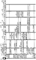
FIG. 1 shows a unified authentication architecture according to one embodiment. -
FIG. 2 shows a table of authentication status and security context according to one embodiment. -
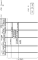
FIG. 3 shows an authentication methodology for an attach request initiated from a visited domain network according to one embodiment. -
FIG. 4 shows an authentication methodology for mobility from 3GPP system access to non-3GPP system access according to one embodiment. -
FIG. 5 shows a single sign-on methodology for user equipment to access multiple applications respectively provided by multiple network slices according to one embodiment. -
FIG. 6 shows a processing platform on which a unified authentication architecture is implemented according to one or more embodiments. - Illustrative embodiments will be described herein with reference to exemplary computing systems, data storage systems, communication networks, processing platforms, systems, user devices, network nodes, network elements, clients, servers, and associated communication protocols. However, it should be understood that embodiments are not limited to use with the particular arrangements described, but are instead more generally applicable to any environment in which it is desirable to provide mechanisms and methodologies for improved security in a communication network.
- While illustrative embodiments are described herein in the context of authentication functions, it is to be appreciated that alternative embodiments may be implemented with other security functions in a straightforward manner given the teachings provided herein.
- In accordance with illustrative embodiments, some main design principles associated with a unified authentication architecture for a 5G or similar network are as follows:
- i) Generally, there are three main types of 5G services/applications (use cases), i.e., eMBB, massive IoT and mission-critical IoT. Illustrative embodiments design a unified authentication architecture for these three types of 5G services/applications with different security requirements. However, the unified authentication architecture is scalable and can also be applied to other types of 5G services/applications (use cases), which may have different security requirements, in a straightforward manner.
- ii) With the introduction of new technologies to 5G networks, such as software-defined networking (SDN) and network function virtualization (NFV), logical functions in the unified authentication architecture can be automatically deployed on-demand.
- iii) The security function in the radio network (e.g., deployed with evolved Node B (eNodeB or eNB) in the same platform) can extract/separate authentication information from radio access request messages such as an attach request, compose authentication request messages, then forward them to the corresponding authentication functions.
- iv) The authentication function has been integrated into a mobility management entity (MME) in 4G networks, a serving general packet radio service support node (SGSN) in 3G networks, and a mobile switching center/visitor location register (MSC/VLR) in 2G networks. In accordance with illustrative embodiments, the authentication function is separated from these network functions and deployed as a stand-alone and common function in a 5G network. Such separation and deployment can be achieved using NFV and SDN technologies. From an evolution point of view, the authentication function in a 5G network should be compatible with the authentication in 4G/3G/2G networks. The centralized authentication function according to illustrative embodiments can also simplify the authentication procedures for the mobility from 3GPP network system access to non-3GPP network system access. The authentication for the mobility from 3GPP system access to non-3GPP network system access, defined in 3GPP Technical Specifications (TS) 33.401 and TS33.234, the disclosures of which are incorporated by reference herein in their entireties, is very complicated and overloaded.
- v) The function of Global Unique Temporary ID/Temporary Mobile Subscriber Identity-International Mobile Subscriber Identity (GUTI/TMSI-IMSI) mapping management has been integrated into MME in 4G networks, SGSN in 3G networks, and MSC/VLR in 2G networks. In accordance with illustrative embodiments, the GUTI/TMSI-IMSI mapping management function is separated from these network functions and deployed as a stand-alone and common function in a 5G network. Network functions such as authentication, mobile management and network resource management interact with the GUTI/TMSI-IMSI mapping management function to retrieve IMSI for further operations/actions (e.g., authentication, handover, network resource allocation).
- According to the above and other design principles, a unified authentication architecture for a 5G or similar network is depicted in
FIG. 1 . - As shown, unified
authentication architecture 100 is illustrated as logical functions (also referred to herein as functions, modules, and/or components) that are implemented across the various subnetworks of a 5G or similar network. The subnetworks comprise a Radio Network 110, a Core Network 130, and a Data Network (Internet) 160. Thesubnetworks architecture 100 further illustrates, the Radio Network 110 resides between the mobile user devices 102-1, 102-2, 102-3, ..., 102-N and an Edge Cloud Network 118. Note that the mobile user devices are depicted inFIG. 1 as various communication devices such as, but not limited to, smart phones (e.g., 102-1), IoT sensors and machines (e.g., 102-2), and vehicles (e.g., 102-3 ... 102-N). Further, the Core Network 130 resides between theedge cloud network 118 and a regional or central data center (DC) 152. - It is also to be noted that the various subnetworks that make up the 5G network are partitioned into "network slices." Network slices (network partitions) comprise a series of function sets (i.e., function chains) for each corresponding service type using NFV on a common physical infrastructure. The network slices are instantiated as needed for a given service. As used herein and in the claims, instantiation is defined as "creating an instance." A network slice or function is thus instantiated when an instance of that network slice or function is created. In some embodiments, this involves installing or otherwise running the network slice or function on one or more host devices of the underlying physical infrastructure.
- As shown in
FIG. 1 , there are three network slices: network slice #1 (104-1) corresponding to an eMBB service; network slice #2 (104-2) corresponding to a massive IoT service; and network slice #3 (104-3) corresponding to a mission-critical IoT service. Each network slice has a control plane and a user plane (Control Plane 106-1 and User Plane 108-1 fornetwork slice # 1; Control Plane 106-2 and User Plane 108-2 fornetwork slice # 2; and Control Plane 106-3 and user plane 108-3 for network slice #3). Each network slice provides the desired function sets to enable a mobile user device (102-1, 102-2, 102-3, ..., 102-N) to communicate with a data network (Internet 154-1 fornetwork slice # 1, Internet 154-2 fornetwork slice # 2, and Internet 154-3 for network slice #3). - As further shown in
architecture 100, each part of a network slice in theRadio Network 110 comprises access points (base stations) 112-1, 112-2, 112, 3, 112-4, 112-5, ... , 112-P, and logical functions including: an Authentication Gateway (Access AuthN GW) function 114 (114-1 fornetwork slice # 1, 114-2 fornetwork slice # 2, and 114-3 for network slice #3); and a Confidentiality/Integrity function 116 (116-1 fornetwork slice # 1, 116-2 fornetwork slice # 2, and 116-3 for network slice #3). - Still further, each part of a network slice in the Core Network 130 comprises logical functions including: an Authentication Orchestrator 132 (132-1 for network slice #1, 132-2 for network slice #2, and 132-3 for network slice #3); a Visited Network Authenticator or V-Authenticator 134 (134-1 for network slice #1, 134-2 for network slice #2, and 134-3 for network slice #3); a GUTI/TMSI-IMSI Mapping Management function 136 (136-1 for network slice #1, 136-2 for network slice #2, and 136-3 for network slice #3); a Data Forwarding Function 137 (137-1 for network slice #1, 137-2 for network slice #2, and 137-3 for network slice #3), Other Network functions 138 (e.g., such as, but not limited to, Mobility Management; 138-1 for network slice #1, 138-2 for network slice #2, and 138-3 for network slice #3); a Confidentiality/Integrity function 139 (network slice #2 only); a Home Network Authenticator or H-Authenticator 144 (144-1 for network slice #1, 144-2 for network slice #2, and 144-3 for network slice #3); and Subscriber and Device Management functions 146 (such as, but not limited to, Authentication, Authorization and Accounting (AAA) service, Home Subscriber service (HSS), Home Location Register (HLR), and Equipment Identity Register (EIR); 146-1 for network slice #1, 146-2 for network slice #2, and 146-3 for network slice #3).
-
Unified authentication architecture 100 also comprisesMaster Authentication Orchestrator 120, deployed in theCore Network 130, which manages network-slice Authentication Orchestrator functions 132-1, 132-2, and 132-3, as will be described in greater detail herein.Security Management function 140 is also part ofarchitecture 100 and provides management of images and provisioning functions as they pertain to security issues. The term "images" as used here illustratively refers to images of virtualized security functions. When necessary, selected images are retrieved from an image repository, encrypted, and transported to a remote site or host and instantiated to provide security service functions. - It is to be appreciated that the 5G security system is comprehensive. The illustrative embodiment of
FIG. 1 depicts wireless network access authentication. So, other security functions such as Firewall/Intrusion Prevention Systems/Intrusion Detection Systems/Deep Packet Inspection (FW/IPS/IDS/DPI) shown inFIG. 1 respectively as modules 142-1, 142-2, 142-3, 148-1, 148-2, 148-3, and 150 will be not explained in detail herein. These functions are described in other corresponding 5G security standards, and are not the focus of illustrative embodiments. - Accordingly, as illustratively depicted in
architecture 100 inFIG. 1 , authentication-related logical functions are deployed for 5G services/applications in corresponding network slices, i.e., network slice #1 (eMBB), network slice #2 (massive IoT), and network slice #3 (mission-critical IoT). Note that the authentication-related logical functions may have different deployments. For example, innetwork slice # 2 for massive IoT, the functions Confidentiality/Integrity 139 is deployed in the Core Network 130 (as compared to theRadio Network 110 fornetwork slices # 1 and #3) as User Plane data may be carried in signaling messages. By way of further example, innetwork slice # 3 for mission-critical IoT, the functions V-Authenticator 134-3 and GUTI/TMSI-IMSI mapping 136-3 maybe deployed in theRadio Network 110 or close to theRadio Network 110, e.g., in edge cloud 118 (as shown), in order to reduce the latency. - Given the above-described
architecture 100 inFIG. 1 , the main logical functions of the architecture will now be further described in detail. -
Master Authentication Orchestrator 120. This logical function operates across network slices and is deployed in theCore Network 130. Further,master Authentication Orchestrator 120 is provisioned with the addresses of Authentication Orchestrators in network slices to be managed, i.e., network-slice Authentication Orchestrator 132-1, network-slice Authentication Orchestrator 132-2, and network slice Authentication Orchestrator 132-3. - The
master Authentication Orchestrator 120 provides an authentication topology view of the 5G network by interacting with the network slice Authentication Orchestrators 132-1, 132-2, and 132-3 and obtaining authentication status. Further, as mentioned,master Authentication Orchestrator 120 manages the network-slice Authentication Orchestrators 132-1, 132-2, and 132-3. Such management comprises: launching a new instantiation of a network-slice Authentication Orchestrator, for example, when a new network slice is created; stopping an existing instantiation of a network-slice Authentication Orchestrator, for example, when a network slice stops providing services; and providing software upgrades for network-slice Authentication Orchestrators. - Still further, the
master Authentication Orchestrator 120 provides single sign-on (SSO) services across network slices. SSO service is important for the same mobile device to access several services/applications deployed in different network slices or for one device to access one service/application across different network slices. As for SSO services across network slices, compliance requirements may include, but are not limited to, complying with mobile network operator's (MNO) policies. For example, some MNOs permit SSO services within their own network domains or across MNO network domains, but some MNOs do not. Another compliance requirement includes complying with polices of network slices and services/applications. For example, massive IoT services/applications permit SSO, but mission-critical IoT services/applications may not permit SSO. Yet another compliance requirement includes complying with security policies. For example, mission-critical IoT services/applications with high-level security cannot accept the authentication result from massive IoT services/applications with low-level security. -
Access AuthN GW 114. An access authentication gateway is provisioned in each network slice (as shown inFIG. 1 , 114-1 fornetwork slice # 1, 114-2 fornetwork slice # 2, and 114-3 for network slice 114-3). This logical function is deployed in theRadio Network 110, and provisioned with the addresses of the V-Authenticator 134, H-Authenticator 144, and Confidentiality/Integrity function 116 to be connected in its corresponding network slice. The Access AuthN GW function recognizes to which network slice authentication messages received from mobile devices 102 (via access points 112) will be sent. - Further, the Access
AuthN GW function 114 extracts/separates authentication information from radio access request messages such as, for example, attach request, composes authentication request messages, then forwards them to the corresponding V-Authenticator 134. Access AuthN GW also receives authentication-related messages (e.g., user authentication request) from the V-Authenticator 134, integrates/converges authentication information into radio access response messages to be forwarded to thedevices 102. TheAccess AuthN GW 114 further obtains the keys and the corresponding indicator of cryptographic algorithms obtained from the authentication procedures, then forwards them to the Confidentiality/Integrity function 116. - Network
slice Authentication Orchestrator 132. A network slice Authentication Orchestrator is provisioned in each network slice (as shown inFIG. 1 , 132-1 fornetwork slice # 1, 132-2 fornetwork slice # 2, and 132-3 for network slice #3). This logical function is deployed in theCore Network 130, and provisioned with the addresses of the V-Authenticator 134 and the H-Authenticator 144 in its corresponding network slice. The network slice Authentication Orchestrator provides an authentication topology view of the network slice, and can manage Authenticators (134 and 144) in the same network slice. Such management includes, but is not limited to: launching a new instantiation of an Authenticator, for example, for a network slice to be scaled out (sometimes referred to as a scale-out operation); stopping an existing instantiation of an Authenticator, for example, for a network slice to be scaled in (sometimes referred to as a scale-in operation); and providing provision, configuration and software upgrades for authenticators. - The network
slice Authentication Orchestrator 132 also supports authentication for roaming scenarios when the V-Authenticator 134 does not know the address of the H-Authenticator 144 (in some cases such as, e.g., the network slice was just launched/installed/instantiated, H-Authenticator was just launched/installed/instantiated, V-Authenticator was just launched/installed/instantiated or not provisioned, etc.). For example, the V-Authenticator 134 retrieves the address of the H-Authenticator 144 from theAuthentication Orchestrator 132 then further sends an authentication request to the home domain network in order to retrieve authentication information through the H-Authenticator 144. TheAuthentication Orchestrator 132 also optimizes authentication procedures during handover. For example, the centralized function knows all subscribers/devices authentication status so that it can simplify authentication and key agreement procedures during handover, especially for the mobility from 3GPP wireless system access to non-3GPP wireless system access. - V/H-
Authenticator 134/144. The authenticator, with the same role of authentication and key agreement which has been integrated into MME in 4G networks, SGSN in 3G networks, and MSC/VLR in 2G networks, is separated from network functions and deployed as a stand-alone and common function in 5G networks in accordance with illustrative embodiments. The Authenticator logical function can be deployed in either theRadio Network 110 or theCore Network 130 depending on the demands of network slices. The Authenticator is provisioned with the addresses of the network-slice Authentication Orchestrator, the Access AuthN GW, the GUTI/TMSI-IMSI mapping, and the other common network functions (e.g., mobile management) in the corresponding network slice. Note that the functions of the Authenticator, as described herein in this section, generally refer to the Authenticator logical function without regard to the home domain/visited domain. When consideration of the visited and home domains come into the process below, the Authenticator logical function will be described as V-Authenticator and H-Authenticator, respectively. - The
unified authentication architecture 100 is compatible with legacy authentication architectures. For example, a subscriber authenticated by a legacy network (e.g., Universal Mobile Telecommunications System (UMTS) or Evolved Packet System (EPS)) plans to handover from the legacy network to the 5G network. As such, the authenticator function (134/144) is configured to retrieve authentication information (e.g., authentication vectors (AVs), pairwise master keys (PMKs)) from the network equipment (e.g., SGSN or MME or Authentication, Authorization and Accounting (AAA) server) in the legacy network. - The Authenticator logical function supports existing authentication mechanisms such as UMTS Authentication and Key Agreement (AKA), EPS AKA, and Wireless Fidelity (Wi-Fi) Protected Access/ Wi-Fi Protected Access II (WPA/WPA2) (for Wi-Fi) as well as new authentication mechanisms to be used for 5G or future wireless networks. A flag such as "UMTS_AKA", "EPS_AKA", "WPA" and "5G_Authentication" (i.e., new authentication mechanism for 5G) is used to identify which authentication mechanisms are to be used. Based on the radio access technology (e.g., Universal Terrestrial Radio Access Network (UTRAN), Long Term Evolution (LTE), Wi-Fi) and device security capabilities (e.g., authentication mechanism, cryptographic algorithms) provided by the
device 102, the authenticator decides which authentication mechanism(s) will be used for wireless access authentication. - The Authenticator retrieves the actual/real identity (e.g., IMSI) of the subscriber based on the temporary identity (e.g., TMSI, GUTI). In a 3GPP network system, actual/real identity of the subscriber is not sent through the network in order to protect subscriber's privacy. In order to perform subscriber authentication, the Authenticator contacts the GUTI/TMSI-IMSI mapping function to fetch the subscriber's actual/real identity.
- When a subscriber registers on the 3GPP network, a temporary identity is assigned (by the authenticator or by other common network functions) to the subscriber after mutual authentication between the subscriber and the network is successfully performed. The mapping relationship between the temporary identity and actual/real identity for the subscriber is stored by the GUTI/TMSI-IMSI mapping function.
- When a subscriber roams to a visited domain network and the Authenticator in the visited domain network (i.e., V-Authenticator 134) has no valid authentication information (e.g., AVs, PMKs) for the subscriber, V-
Authenticator 134 contacts H-Authenticator 144 (with the help of the network-slice authentication orchestrator 132 if V-Authenticator 134 does not know the address of H-Authenticator 144, e.g., in some cases such as the network slice was just launched/installed/instantiated, H-Authenticator was just launched/installed/instantiated, V-Authenticator was just launched/installed/instantiated or not provisioned, etc.) to get authentication information in the home domain network (i.e., H-Authenticator 144). - When a subscriber accesses the wireless network and the Authenticator has no valid authentication information (e.g., authentication vectors, PMKs) for the subscriber, the authenticator contacts the Subscriber and Device Management function 146 to fetch corresponding authentication information.
- Illustrative embodiments provide management of authentication status and security context for subscribers and/or devices in order to optimize authentication/re-authentication procedures.
FIG. 2 shows an authentication status table 200 according to one embodiment. As shown, for example for a subscriber uniquely identified byIMSI# 1, the table 200 stores the following information: authentication status (successful); authentication mechanism (EPS AKA); active authentication vectors/information (EPS AV) (i.e. security context); reserved authentication vectors/information (EPS AVs) (i.e. security context); and address of legacy authenticator (none). Similar status information is stored for devices uniquely identified by their IMEIs or network interfaces uniquely identified by their MAC addresses, as shown further shown in table 200. It is to be understood that there may be one or more such tables to record authentication status for subscribers, devices, and/or network interfaces. These one or more tables are stored in the authenticator (function 134, 144, or some combination thereof). - Illustrative embodiments also optimize authentication procedures during handover. The Authenticator records subscribers/devices authentication status and security context so that the procedures of authentication and key agreement during handover are simplified, especially for the mobility from 3GPP wireless system access to non-3GPP wireless system access. In 3GPP TS33.402 and TS23.402, the disclosures of which are incorporated by reference herein in their entireties, even though user equipment (UE) has already been authenticated by the source radio access network, mutual authentication between UE and the target network has to be done again in order to obtain the keys used to protect the air link before handover. In this way, authentication communications over the air link is overloaded and handover latency is increased. Advantageously, in accordance with illustrative embodiments, there is no need to do mutual authentication between UE and the target network again since the Authenticator knows the authentication status and security context.
- The Authenticator notifies the other common network functions (e.g., mobile management) that the authentication is successful or failed. If authentication is successful, the network resource allocation goes on to further steps, otherwise it is stopped.
- GUTI/TMSI-
IMSI mapping 136. The function of GUTI/TMSI-IMSI mapping management, with the role of managing the relationship between the temporary identity and IMSI (which has been integrated into MME in 4G, SGSN in 3G, and MSC/VLR in 2G) is separated from network functions and deployed as a stand-alone and common function in 5G networks in accordance with illustrative embodiments. A hierarchy of consolidated mapping tables is employed, in one embodiment, to manage the relationship between temporary identity and IMSI, e.g., the mapping relationship between GUTI and IMSI, and between TMSI and IMSI, etc. Such tables are stored in themapping component 136. - Subscriber and Device Management 146. For a commercial network, subscriber and device management is typically deployed separately from each other. However, in order to simplify the description, subscriber and device management are described together and depicted as one function in
FIG. 1 . - Subscriber management may be implemented as one existing subscriber management system such as a Home Location Register/Home Subscriber Server (HLR/HSS) and an AAA Server, the combination of these existing subscriber management systems, or a new subscriber management system. Device management may be implemented as one existing device management system such as Equipment Identity Register (EIR) and Open Mobile Alliance (OMA) Device Management (DM) system, the combination of these existing device management systems, or a new device management system.
- Confidentiality/
Integrity 116/139. The Confidentiality/Integrity logical function, with the same role of providing confidentiality and integrity protection which is integrated into a Radio Network Controller (RNC) or eNB (confidentiality and integrity protection for wireless communication), and MME (confidentiality and integrity protection for non-access stratum (NAS) messages), can be deployed in either theRadio Network 110 or theCore Network 130 depending on the demands of services/applications. The logical function is provisioned with the address of the AccessAuthN GW function 114 for its corresponding network slice. - The Confidentiality/Integrity logical function obtains the keys and the corresponding indicator of cryptographic algorithms from the Access AuthN GW function, and then performs confidentiality and integrity protection for signaling messages on the Control Plane 106 and user data on the User Plane 108 according to the requirements from services/applications.
-
Security Management 140. The Security Management logical function is a component deployed in theCore Network 130. The function provides for, across network slices, image management, security provisioning, and software updates for all authentication-related functions. - Given the above detailed description of the various logical functions (functions, modules, and/or components) of
unified authentication architecture 100, the following detailed description illustrates network access authentication for three scenarios in a 5G network. In order to simplify the description, the following non-limiting assumptions are made: - 1- Only authentication procedures are described.
- 2- The communication between any two logical functions is secured by transport layer security/Internet Protocol security (TLS/IPsec) or physical security.
- 3- The logical functions Access AuthN GW and Confidentiality/Integrity are deployed in the same platform with a wireless access node (e.g., Evolved Universal Terrestrial Radio Access Network (E-UTRAN) access node, Wireless Local Area Network (WLAN) access node).
- 4- For the handover from E-UTRAN to WLAN: (a) WLAN access node and E-UTRAN access node are trusted by each other as defined in 3GPP TS23.402; (b) handover between EPS E-UTRAN and WLAN is in a single-connect mode with non-roaming.
-
FIG. 3 shows anauthentication methodology 300 for an attach request initiated from a visited domain network according to one embodiment.Authentication methodology 300 assumes that one user initiates the Attach Request from a visited EPS network while there is no mapping relationship between GUTI and IMSI for this user in the visited EPS network. Thus, the visited EPS network has to retrieve authentication information from the home EPS network. For this scenario, it is also assumed that a new network slice is instantiated and no authentication for roaming access is previously performed. It is further assumed that a new instance of H-Authenticator is installed and starts to operate and V-Authenticator 134 does not know the address of H-Authenticator 144. - When a new network slice is created, the network-
slice authentication orchestrator 132 chooses the instances ofAccess AuthN GW 114, Confidentiality/Integrity 116, V-Authenticator 134, GUTI/TMSI-IMSI mapping management 136, and H-Authenticator 144 (with HSS/HLR 302), and then creates a function chain (together with other network functions 304 such as, but not limited to, Mobility Management Function (MMF) or Core Control Function (CCF) in Next Generation Network Architecture S2-165374, the disclosure of which is incorporated by reference herein in its entirety) for access authentication. - Following creation of the above-described function chain,
authentication methodology 300 is performed. Note that the enumerated steps described below correspond to the steps labeled inFIG. 3 . - Step 0: The end user turns on his mobile phone (device 102) in a visited EPS network after, for example, a long-haul flight. The user equipment (UE) of the mobile device sends the message Attach Request to the visited E-UTRAN access node 112 (comprised of Access
AuthN GW function 114 and Confidentiality/Integrity function 116). - Step 1: The Access AuthN GW function 114 (deployed in visited E-UTRAN access node 112) extracts authentication-related information (e.g., UE security capability, GUTI, etc.) from the Attach Request and composes a message, i.e., Authentication Request (GUTI, "EPS_AKA", UE other security capability, etc.) Note that it is assumed that GUTI was obtained in the last connection to a 3GPP network, while EPS_AKA is a field for the Authenticator function (134/144) to know which authentication mechanism is used for the user. Then, the Access AuthN GW function 114 forwards an Authentication Request to the V-
Authenticator function 134. Note also that other functions in the visitedE-UTRAN access node 112 compose other messages such as, but not limited to, radio resource allocation messages, and then forwards them to corresponding network functions such as, but not limited to, mobility management. However, these additional messages are not a main focus here and will not be further described. - Step 2: The V-
Authenticator function 134 receives the message Authentication Request and identifies the authentication mechanism for this user as EPS AKA. The V-Authenticator function sends the message IMSI Request (GUTI) to the GUTI/TMSI-IMSI Mapping function 136 to retrieve the IMSI of the user. However, there is no valid mapping relationship between GUTI and IMSI for this user in the visited EPS network. So, the IMSI request fails to retrieve the IMSI of the user in visited EPS network. - Step 3: The V-
Authenticator function 134 sends the message Identity Request to the UE (of device 102) through the AccessAuthN GW function 114. The UE responds to the V-Authenticator function through the Access AuthN GW function with the IMSI. The messages Identity Request/Response are defined in 3GPP TS 33.401. - Step 4bis: The V-
Authenticator function 134 retrieves the address of the H-Authenticator function 144 from theAuthentication Orchestrator function 132. - Step 4: Based on the IMSI of this user, the V-
Authenticator function 134 retrieves authentication data from the home EPS network through the H-Authenticator function 144 and the HSS/HLR 302. The messages Authentication Data Request/Response are defined in 3GPP TS33.401. - Step 5: The V-
Authenticator function 134 sends the message User Authentication Request to the UE through the AccessAuthN GW function 114. The UE generates corresponding keys and authentication data which are defined in 3GPP TS33.401. The UE responds to the V-Authenticator function 134 through the AccessAuthN GW function 114 with a "RES" message. The V-Authenticator function 134 authenticates the user. The messages User Authentication Request/Response are defined in 3GPP TS33.401. - Step 6: The V-
Authenticator function 134 stores the authentication status and security context and assigns a temporary identity GUTI for this user. It is possible for other network functions 304 to assign GUTI for this user. In this case, the V-Authenticator function 134 notifies the corresponding network function to assign a GUTI for this user. The GUTI-IMSI mapping relationship is kept in the GUTI/TMSI-IMSI Mapping function 136 through the messages IMSI-GUTI storage request/response. - Step 7: The V-
Authenticator function 134 responds to the AccessAuthN GW function 114 that the authentication of the user is successful by sending the message Authentication Response (sub-step 7.1). The V-Authenticator function 134 notifies other network functions 304 (e.g., mobility management) that the authentication of the user is successful, and the Other Network functions 304 respond (sub-steps 7.2). The other network functions can go further to allocate network resource for this user. - Step 8: The Access
AuthN GW function 114 sends keys and related indicators from V-Authenticator function to the Confidentiality/Integrity function 116 through the messages Key & Indicator Notify request/response. - Step 9: The UE receives an Attach Response message from the network side.
-
FIG. 4 shows an authentication methodology 400 for the mobility from 3GPP system access to non-3GPP system access according to one embodiment. Methodology 400 illustrates the authentication procedure for one user handover from a 3GPP EPS network to a WLAN network with the following two assumptions: (a) the WLAN access node and the E-UTRAN access node are trusted by each other as defined in 3GPP TS23.402; and (b) handover between EPS E-UTRAN and WLAN is in a single-connect mode with non-roaming status. - Following creation of the function chain depicted across the top of
FIG. 4 , authentication methodology 400 is performed. Note that the enumerated steps described below correspond to the steps labeled inFIG. 4 . -
Step 0. The UE (of device 102) is connected to the 3GPP EPS network via access node 112-E (comprised of Access AuthN GW function 114-E and Confidentiality/Integrity function 116-E). -
Step 1. The UE discovers WLAN access node 112-W (comprised of Access AuthN GW function 114-W and Confidentiality/Integrity function 116-W). The UE initiates a handover request. -
Step 2. The UE sends the message HO Request (Identity, Network Access Identifier Wireless Local Area Network NAIWLAN) to the E-UTRAN access node 112-E. Note that parameters Identity and NAI are defined in 3GPP TS23.402 and 3GPP TS33.402. The Access AuthN GW function 114-E (deployed in E-UTRAN access node) extracts authentication-related information (e.g., Identity, NAIWLAN, UE security capability) from the message HO Request and composes a message, i.e., HO Security Context Request (Identity, NAIWLAN, UE security capability). -
Step 3. The Access AuthN GW function 114-E sends the message Handoff (HO) Security Context Request to the Authenticator function. Here, the Authenticator function will be referred to as 144 (i.e., H-Authenticator function 144), although it is to be understood that, in alternative embodiments, the Authenticator function could be the V-Authenticator 134 when there is roaming authentication needed. -
Step 4. After receiving the message HO Security Context Request, the Authenticator function 144 forwards HO Security Context Request to AAA Server 404 (sub-step 4.0).AAA Server 404 retrieves the IMSI from the GUTI/TMSI-IMSI Mapping function 136 (sub-step 4.1). Then, theAAA Server 404 retrieves the present EPS AV (authentication vector) in use according to the IMSI from its authentication status database (e.g., table 200 inFIG. 2 ). TheAAA Server 404 derives a Master Session Key (MSK) and an Extended Master Session Key (EMSK) from a Key Access Management Entity (KASME) and stores them (with identity, authentication mechanism) into its authentication status database (sub-step 4.2).AAA Server 404 forwards a security context (e.g., Identity, MSK, EMSK) to the Authenticator function 144 (sub-step 4.3). -
Step 5. TheAuthenticator function 144 sends a security context (e.g., Identity, MSK, EMSK) to the Access AuthN GW function 114-W deployed in the WLAN access node 112-W through the messages HO Security Context Notify Request/Response (sub-step 5.1). The Access AuthN GW function 114-W derives the keys to secure WLAN wireless access from the keys MSK and EMSK and stores them into its database, and then sends the keys and related indicators to the Confidentiality/Integrity function 116-W to secure WLAN wireless access through the messages Key & Indicator Notify request/response (sub-step 5.2). -
Step 6. TheAuthenticator function 144 sends the message HO Security Context Response (Key Set Identifier Access Security Management Entity or KSIASME) to the Access AuthN GW function 114-E in the E-UTRAN access node 112-E. -
Step 7. The Access AuthN GW function 114-E in E-UTRAN access node 112-E sends the message Key Materials Notify Request (KSIASME) to the UE. -
Step 8. After receiving the message Key Materials Notify Request (KSIASME), the UE derives MSK and EMSK from KASME, and then derives the keys to secure WLAN access from MSK and EMSK. -
Step 9. The UE sends the message Key Materials Notify Response to the Access AuthN GW function 14-E in the E-UTRAN access node 112-E. -
Step 10. The UE receives the message HO Response from the network side. -
Step 11. The UE sends the message HO completed to the Access AuthN GW function 114-W in the WLAN access node 112-W. -
Step 12. WLAN access node sends the message HO Notify to the function Authenticator to record the authentication status. -
Step 13. TheAuthenticator function 144 initiates the message Subscriber Profile Retrieval and registration to the HSS/HLR 402. - Radio access resources are released in the EPS E-UTRAN access node 112-E once the
device 102 is successfully handed over to the WLAN access node 112-W. - Comparing authentication methodology 400 to the authentication procedure of a handover from a 3GPP system to a non-3GPP system defined in 3GPP TS33.402 and TS23.402, advantageous differences include, but are not limited to:
- 1- There is no mutual authentication between the UE and target network (i.e., WLAN access node).
- 2- The number of steps for key negotiation through the air link in methodology 400 is smaller than that defined in in 3GPP TS33.402 and TS23.402.
- In this way, handover latency is reduced and scarce radio access resources are saved.
-
FIG. 5 shows a single sign-onmethodology 500 for user equipment to access multiple applications respectively provided by multiple network slices according to one embodiment. More particularly,methodology 500 illustrates a single sign-on (SSO) service for the same UE to access two applications respectively provided by two network slices, i.e., massive IoT in network slice #2 (104-2) and eMBB in network slice #1 (104-1). It is assumed that a user with a UE is accessing a mobile multimedia service (eMBB) provided by thenetwork slice # 1 which is an EPS network. After some time, the user with the same UE plans to access a massive IoT service provided by thenetwork slice # 2 which is also an EPS network. In this case, there is no need to do mutual authentication between the user and thenetwork slice # 2 since the authentication result and related security context of the user in thenetwork slice # 1 can be reused for thenetwork slice # 2. It is further assumed that there is no roaming for the user connecting to two network slices. - Following creation of the function chains depicted across the top of
FIG. 5 ,authentication methodology 500 is performed. Note that the enumerated steps described below correspond to the steps labeled inFIG. 5 . -
Step 0. The UE (of device 102) is connected to networkslice # 1 and accessing multimedia services. The same UE plans to connect tonetwork slice # 2 and access a massive IoT service. The UE is aware of connecting to networkslice # 1 and agrees to use the authentication result ofnetwork slice # 1 to register fornetwork slice # 2. The UE sends the message Attach Request to Access AuthN GW function 114-2 innetwork slice # 2. -
Step 1. The Access AuthN GW function 114-2 innetwork slice # 2 extracts/separates authentication-related information (e.g., UE security capability, GUTI with corresponding network slice number i.e.network slice # 1, etc.) from the Attach Request and composes a message, i.e., Authentication Request (GUTI with corresponding network slice number, i.e.network slice # 1, "EPS_AKA", UE other security capability, "login with SSO", etc.). Then, the Access AuthN GW function 114-2 forwards Authentication Request to the Authenticator function 144-2 innetwork slice # 2. Again here, note that the Authenticator function is assumed to be the H-Authenticator 144, but in alternative embodiments that involve roaming, can include the V-Authenticator function 134. -
Step 2. The Authenticator function 144-2 innetwork slice # 2 receives the message Authentication Request (GUTI with corresponding network slice number, i.e.,network slice # 1, "EPS_AKA", UE other security capability, "login with SSO", etc.) and contacts the Authenticator function 144-1 innetwork slice # 1 to retrieve authentication data. The Authenticator function 144-2 innetwork slice # 2 sends the message SSO Request (GUTI with corresponding network slice number, i.e.,network slice # 1, "EPS_AKA", UE other security capability, "login with SSO", etc.) to the Authenticator function 144-1 innetwork slice # 1 via the Authentication Orchestrator 132-2 innetwork slice # 2,master Authentication Orchestrator 120, and Authentication Orchestrator 132-1 innetwork slice # 1. -
Step 3. The Authenticator function 144-1 innetwork slice # 1 retrieves the IMSI from the GUTI/TMSI-IMSI Mapping function 136-1 through the messages IMSI Request/Response. -
Step 4. The Authenticator function 144-1 innetwork slice # 1 derives the key KEYNS from KASME which has been obtained from the key negotiation between the UE and the Authenticator function 144-1 innetwork slice # 1. -
Step 5. The Authenticator function 144-1 innetwork slice # 1 responds to the Authenticator function 144-2 innetwork slice # 2 with KSIASME and the key KEYNS via the Authentication Orchestrator 132-1 innetwork slice # 1,master Authentication Orchestrator 120, and Authentication Orchestrator 132-2 innetwork slice # 2. The response message is SSO Response. -
Step 6. The Authenticator function 144-2 innetwork slice # 2 derives K"ASME from KEYNS, K"MME from K"ASME, and K"eNB from K"MME. -
Step 7. The Authenticator function 144-2 innetwork slice # 2 sends the message Authentication Response (KSIASME) to the Access AuthN GW function 114-2 in network slice #2 (sub-step 7.1). The Authenticator function 144-2 innetwork slice # 2 stores the authentication status and assigns the temporary identity GUTI for the user, and then stores the mapping relationship between GUTI and IMSI into the GUTI/TMSI-IMSI mapping function 136-2 through the messages IMSI-GUTI Storage Request/Response (sub-steps 7.2). It is possible for Other Network functions 502 to assign GUTI for this user (sub-step 7.3). In this case, the Authenticator function notifies the corresponding network function to assign GUTI for this user. The Authenticator function notifies Other Network functions 502, such as, but not limited to, mobility management, that the authentication of the user is successful. Other Network functions 502 can go further to allocate network resources for this user. -
Step 8. The Access AuthN GW function 114-2 innetwork slice # 2 derives K"RRCenc, K"RRcint, K"UPenc, and K"UPint from K"eNB (sub-step 8.1) and then sends keys and related indicators to the Confidentiality/Integrity function 116-2 innetwork slice # 2 through the messages Key & Indicator Notify request/response (sub-step 8.2). -
Step 9. The Access AuthN GW function 114-2 innetwork slice # 2 sends the message Key Materials Notify Request (KSIASME) to the UE. -
Step 10. The UE derives the key KEYNS from KASME (negotiated between UE and Authenticator function 144-1 in network slice #1), derives K"ASME from KEYNS, derives K"MME from K"ASME, derives K"eNB from K"MME, derives K"RRCenc, K"RRCint, K"UPenc, and K"UPint from K"eNB. -
Step 11. The UE responds to the Access AuthN GW function 144-2 innetwork slice # 2 with the message Key Materials Notify Response. -
Step 12. The UE receives the message Attach Response from thenetwork slice # 2. - Turning now to
FIG. 6 , a processing platform is shown on which a unified authentication architecture (e.g., 100 inFIG. 1 ) is implemented according to one or more embodiments. Theprocessing platform 600 in this embodiment comprises a plurality of processing devices denoted 602-1, 602-2, 602-3, ... 602-P, which communicate with one another over anetwork 604. One or more of the components and/or modules of architecture 100 (e.g., APIs, components, databases, etc.) may therefore each run on one or more computers or other processing platform elements, each of which may be viewed as an example of what is more generally referred to herein as a "processing device." As illustrated inFIG. 6 , such a device generally comprises at least one processor and an associated memory, and implements one or more functional modules for instantiating and/or controlling features of systems and methodologies described herein. Multiple elements or modules may be implemented by a single processing device in a given embodiment. - The processing device 602-1 in the
processing platform 600 comprises aprocessor 610 coupled to amemory 612. Theprocessor 610 may comprise a microprocessor, a microcontroller, an application-specific integrated circuit (ASIC), a field programmable gate array (FPGA) or other type of processing circuitry, as well as portions or combinations of such circuitry elements. Components of a system as disclosed herein can be implemented at least in part in the form of one or more software programs stored in memory and executed by a processor of a processing device such asprocessor 610. Memory 612 (or other storage device) having such program code embodied therein is an example of what is more generally referred to herein as a processor-readable storage medium. Articles of manufacture comprising such processor-readable storage media are considered embodiments. A given such article of manufacture may comprise, for example, a storage device such as a storage disk, a storage array or an integrated circuit containing memory. The term "article of manufacture" as used herein should be understood to exclude transitory, propagating signals. - Furthermore,
memory 612 may comprise electronic memory such as random access memory (RAM), read-only memory (ROM) or other types of memory, in any combination. The one or more software programs when executed by a processing device such as the processing device 602-1 causes the device to perform functions associated with one or more of the components/steps of system/methodology 500. One skilled in the art would be readily able to implement such software given the teachings provided herein. Other examples of processor-readable storage media embodying embodiments may include, for example, optical or magnetic disks. - Also included in the processing device 602-1 is
network interface circuitry 614, which is used to interface the processing device with thenetwork 604 and other system components. Such circuitry may comprise conventional transceivers of a type well known in the art. - The
other processing devices 602 of theprocessing platform 600 are assumed to be configured in a manner similar to that shown for processing device 602-1 in the figure. - The
processing platform 600 shown inFIG. 6 may comprise additional known components such as batch processing systems, parallel processing systems, physical machines, virtual machines, virtual switches, storage volumes, logical units, etc. Again, the particular processing platform shown inFIG. 6 is presented by way of example only, and thearchitecture 100 ofFIG. 1 may include additional or alternative processing platforms, as well as numerous distinct processing platforms in any combination. - Also, numerous other arrangements of servers, computers, storage devices or other components are possible. Such components can communicate with other elements of the system over any type of network, such as a wide area network (WAN), a local area network (LAN), a satellite network, a telephone or cable network, a storage network, a converged network or various portions or combinations of these and other types of networks.
- Furthermore, it is to be appreciated that the
processing platform 600 ofFIG. 6 can comprise virtual machines (VMs) implemented using a hypervisor. A hypervisor is an example of what is more generally referred to herein as "virtualization infrastructure." The hypervisor runs on physical infrastructure.Processing platform 600 may also include multiple hypervisors, each running on its own physical infrastructure. As is known, VMs are logical processing elements that may be instantiated on one or more physical processing elements (e.g., servers, computers, processing devices). That is, a VM generally refers to a software implementation of a machine (i.e., a computer) that executes programs like a physical machine. Thus, different VMs can run different operating systems and multiple applications on the same physical computer. Virtualization is implemented by the hypervisor which is directly inserted on top of the computer hardware in order to allocate hardware resources of the physical computer dynamically and transparently. The hypervisor affords the ability for multiple operating systems to run concurrently on a single physical computer and share hardware resources with each other. - As described herein, illustrative embodiments provide a unified authentication architecture to meet different security requirements from 5G (or similar) services/applications (e.g., eMBB services, massive IoT services, mission-critical IoT services) as well as to provide key negotiation and agreement for confidentiality and integrity protection. More particularly, illustrative embodiments provide a flexible architecture for security service on demand so that different security requirements from different applications can be met without altering underlying network topology. This architecture can be used to design 5G security with different security requirements from various scenarios including, but not limited to, eMBB, massive IoT and critical IoT. It is to be understood that IoT services, such as massive IoT, mission-critical IoT, and other IoT services, can be considered examples of a broader classification of services referred to herein as "machine-to-machine" services. In such a service, one machine (e.g., IoT device) communicates with at least one other machine (e.g., another IoT device). Illustrative embodiments may be implemented with one or more machine-to-machine services.
- In the various scenarios illustratively described herein, it is to be appreciated that the security service being provided by the instantiated security service function chain is mutual authentication between a subscriber and the network for eMBB service, or mutual authentication between a device and the network for an IoT service. This means that the authentication is either for a subscriber using a device with a subscriber or user identity module/card (e.g., eMBB service) or for a device with no subscriber or user identity module/card (e.g., massive IoT service). As such, while the distinction between a subscriber and a device for purposes of access authentication are specified herein, a subscriber (using a device with a subscriber or user identity module, e.g., Subscriber Identity Module (SIM) card, Universal Mobile Telecommunication System (UMTS) SIM (USIM) card, User Identity Module (UIM) card, removable UIM (R-UIM) card) or a device (with no SIM/USIM/UIM/R-UIM card) may be generally referred to herein as an entity accessing or seeking access (or more simply an "entity") to a network slice, network service, and/or communication network. However, other entities accessing or seeking access may also be characterized in this manner.
Claims (15)
- A method comprising:creating a security service function chain comprising a set of security service functions, wherein the security service function chain is created in response to instantiation of a given network partition in a communication network, wherein the communication network supports instantiation of a plurality of network partitions for providing a respective plurality of network services; andutilizing the security service function chain to perform at least one security service for an entity performing one of accessing and seeking access to a network service corresponding to the given network partition;wherein one or more of the steps are performed by a processing device (602-1, ... 602P).
- The method of claim 1, wherein the at least one security service comprises mutual authentication between the entity and the communication network.
- The method of claim 2, wherein creation of the security service function chain utilized to perform the mutual authentication is managed by an authentication orchestrator (132) created for the given network partition.
- The method of claim 3, wherein the security service function chain comprises at least a subset of an authentication gateway function (114), an authentication function (134, 144), an identity mapping function (136), and a confidentiality and integrity function (116).
- The method of claim 4, wherein the authentication gateway function (114) is configured to:receive a message from the entity;extract authentication information from the received message;compose an authentication request message from the extracted authentication information; andforward the authentication request message to the authentication function.
- The method of claim 4, wherein the authentication gateway function (114) is configured to:receive an authentication-related message from the authentication function;integrate authentication information from the received message into an access response message; andforward the access response message to the entity.
- The method of claim 4, wherein the authentication gateway function (114) is configured to:receive key-related information from the authentication function; andforward the key-related information to the confidentiality and integrity function.
- The method of claim 4, wherein the authentication function (134, 144) is configured to determine from a plurality of authentication mechanisms an authentication mechanism to use to perform access mutual authentication between the entity and the communication network.
- The method of claim 4, wherein the authentication function (134, 144) is configured to retrieve, from the identity mapping function, an actual identity associated with the entity based on a temporary identity associated with the entity assigned by the communication network.
- The method of claim 4, wherein the authentication function (134, 144) operating in a visited domain network in the communication network is configured to obtain, through the authentication orchestrator of the given network partition, authentication information for the entity from another authentication function in a home domain network in the communication network.
- The method of claim 4, wherein the authentication function (134, 144) is configured to maintain a database of the authentication status and security context for entities performing one of accessing and seeking access to the communication network through the given network partition.
- The method of claim 11, wherein the authentication function (134, 144) is configured to, after the entity initiates a handover to a target network, reference the database of authentication status and security context for the entity to avoid performing a mutual authentication between the entity and the target network.
- The method of claim 4, wherein the identity mapping function (136) is configured to manage a relationship between an actual identity associated with the entity and a temporary identity assigned to the entity by the communication network.
- The method of claim 4, wherein the confidentiality and integrity function (116) is configured to provide protection for signaling messages on a control plane of the network partition and for user data on a user plane of the network partition.
- An apparatus comprising:a memory; anda processor operatively coupled to the memory and configured to read program steps on said memory, said program steps configuring the processor to implement a method according to any of claims 1-14.
Applications Claiming Priority (1)
| Application Number | Priority Date | Filing Date | Title |
|---|---|---|---|
| PCT/CN2016/099206 WO2018049646A1 (en) | 2016-09-18 | 2016-09-18 | Unified security architecture |
Publications (3)
| Publication Number | Publication Date |
|---|---|
| EP3513531A1 EP3513531A1 (en) | 2019-07-24 |
| EP3513531A4 EP3513531A4 (en) | 2020-04-29 |
| EP3513531B1 true EP3513531B1 (en) | 2021-06-23 |
Family
ID=61618596
Family Applications (1)
| Application Number | Title | Priority Date | Filing Date |
|---|---|---|---|
| EP16916026.4A Active EP3513531B1 (en) | 2016-09-18 | 2016-09-18 | Unified security architecture |
Country Status (4)
| Country | Link |
|---|---|
| US (1) | US11240660B2 (en) |
| EP (1) | EP3513531B1 (en) |
| CN (1) | CN109964453B (en) |
| WO (1) | WO2018049646A1 (en) |
Families Citing this family (14)
| Publication number | Priority date | Publication date | Assignee | Title |
|---|---|---|---|---|
| ES2870553T3 (en) * | 2017-03-17 | 2021-10-27 | Nec Corp | Network device, communication method and software |
| HUE059620T2 (en) * | 2018-02-19 | 2022-12-28 | Ericsson Telefon Ab L M | Supporting interworking and/or mobility between different wireless communication systems |
| CN110621045B (en) * | 2018-06-20 | 2022-05-13 | 华为云计算技术有限公司 | Method for service routing of Internet of things |
| CN111465011B (en) * | 2019-01-18 | 2021-07-16 | 华为技术有限公司 | Cross-network access method, device, storage medium and communication system |
| US11576039B2 (en) * | 2019-09-12 | 2023-02-07 | At&T Mobility Ii Llc | Authentication of a 3G cellular device over 4G mobile network |
| CN110839036B (en) * | 2019-11-19 | 2021-09-03 | 武汉思普崚技术有限公司 | Attack detection method and system for SDN (software defined network) |
| CN111385794B (en) * | 2020-03-19 | 2022-03-18 | 中国电子科技集团公司第三十研究所 | Mobile communication network privacy protection method and system for industry users |
| US11678249B2 (en) * | 2020-03-24 | 2023-06-13 | Qualcomm Incorporated | Low band assisted routing for multi-hop networks with high band data traffic |
| CN113747436B (en) * | 2020-05-14 | 2022-09-23 | 华为技术有限公司 | Communication system, server, communication method and device |
| CN111885602B (en) * | 2020-07-27 | 2021-04-27 | 西南交通大学 | Heterogeneous network-oriented batch switching authentication and key agreement method |
| WO2022067831A1 (en) * | 2020-09-30 | 2022-04-07 | 华为技术有限公司 | Method and apparatus for establishing secure communication |
| CN114760626B (en) * | 2021-10-18 | 2024-04-02 | 西安电子科技大学 | Self-adaptive combined authentication method for 5G large-scale terminal |
| US11461459B1 (en) * | 2021-11-02 | 2022-10-04 | Kandji, Inc. | User device authentication gateway module |
| CN114978709B (en) * | 2022-05-24 | 2023-06-27 | 成都市第三人民医院 | Lightweight unified security authentication method for medical application |
Family Cites Families (22)
| Publication number | Priority date | Publication date | Assignee | Title |
|---|---|---|---|---|
| US7233997B1 (en) * | 1997-06-26 | 2007-06-19 | British Telecommunications Plc | Data communications |
| US7882247B2 (en) * | 1999-06-11 | 2011-02-01 | Netmotion Wireless, Inc. | Method and apparatus for providing secure connectivity in mobile and other intermittent computing environments |
| US7500104B2 (en) * | 2001-06-15 | 2009-03-03 | Microsoft Corporation | Networked device branding for secure interaction in trust webs on open networks |
| US7607069B1 (en) | 2002-06-28 | 2009-10-20 | Sun Microsystems, Inc. | Computer system including network slices that map to field replaceable units |
| BRPI0513195A (en) * | 2004-07-09 | 2008-04-29 | Matsushita Electric Ind Co Ltd | systems for administering user authentication and authorization, and for user support, methods for administering user authentication and authorization, for accessing services from multiple networks, for the authentication controller to process an authentication request message, to select the combination of authentication controllers. search result authentication, authenticating a user, and finding the way to a domain having business relationship with the home domain, for the authorization controller to process the service authorization request message, and perform service authorization for a domain controller. authentication and authorization perform authentication and service authorization, to protect the user token, and for the user's home domain access control authority to provide the authentication controller with a limited user signature profile information, to achieve authentication and authorize fast access, and to achieve single registration to access multiple networks, and formats for subscription capability information, for a user symbol, for a domain having business relationship with a user's home domain to request authentication and authorization assertion , and for a user terminal to indicate their credentials for accessing multiple networks across multiple administrative domains. |
| CN101330723B (en) * | 2007-06-19 | 2012-12-12 | 华为技术有限公司 | Method and system for establishing tunnel in evolution network |
| CN101163056B (en) * | 2007-11-13 | 2011-09-21 | 中兴通讯股份有限公司 | Method of processing monitor sign of microwave access global intercommunication system |
| JP4966432B2 (en) | 2008-04-11 | 2012-07-04 | テレフオンアクチーボラゲット エル エム エリクソン(パブル) | Access via non-3GPP access network |
| CN102932382B (en) | 2011-08-08 | 2018-03-23 | 中兴通讯股份有限公司 | Safe supply method and system, type of service acquisition methods on demand |
| CN104506406B (en) * | 2011-11-03 | 2018-10-30 | 华为技术有限公司 | A kind of authentication equipment |
| WO2013096758A1 (en) | 2011-12-21 | 2013-06-27 | Akamai Technologies, Inc. | Security policy editor |
| US8797905B2 (en) * | 2012-08-09 | 2014-08-05 | International Business Machines Corporation | Lawful interception in a mobile data network with data offload at the basestation |
| JP6708626B2 (en) * | 2014-05-02 | 2020-06-10 | コニンクリーケ・ケイピーエヌ・ナムローゼ・フェンノートシャップ | Method and system for providing security from a wireless access network. |
| US9462084B2 (en) | 2014-12-23 | 2016-10-04 | Intel Corporation | Parallel processing of service functions in service function chains |
| EP3281434B1 (en) * | 2015-04-08 | 2020-02-12 | Telefonaktiebolaget LM Ericsson (publ) | Method, apparatus, and system for providing encryption or integrity protection in a wireless network |
| US9762402B2 (en) * | 2015-05-20 | 2017-09-12 | Cisco Technology, Inc. | System and method to facilitate the assignment of service functions for service chains in a network environment |
| US10129894B2 (en) * | 2016-03-04 | 2018-11-13 | Huawei Technologies Co., Ltd. | Systems and methods for performing traffic engineering through network slices |
| US10028128B2 (en) * | 2016-04-29 | 2018-07-17 | Motorola Mobility Llc | Procedures to support network slicing in a wireless communication system |
| US11026060B2 (en) * | 2016-05-13 | 2021-06-01 | Huawei Technologies Co., Ltd. | Systems and methods for network slice attachment and configuration |
| US20170339688A1 (en) * | 2016-05-17 | 2017-11-23 | Industrial Technology Research Institute | Method of network slicing and related apparatuses using the same |
| KR102529714B1 (en) * | 2016-06-15 | 2023-05-09 | 인터디지탈 패튼 홀딩스, 인크 | Network slice discovery and selection |
| WO2017214932A1 (en) * | 2016-06-16 | 2017-12-21 | 华为技术有限公司 | Network-slice resource management method and apparatus |
-
2016
- 2016-09-18 CN CN201680090879.0A patent/CN109964453B/en active Active
- 2016-09-18 US US16/333,647 patent/US11240660B2/en active Active
- 2016-09-18 WO PCT/CN2016/099206 patent/WO2018049646A1/en active Application Filing
- 2016-09-18 EP EP16916026.4A patent/EP3513531B1/en active Active
Also Published As
| Publication number | Publication date |
|---|---|
| CN109964453A (en) | 2019-07-02 |
| US20190261179A1 (en) | 2019-08-22 |
| EP3513531A1 (en) | 2019-07-24 |
| US11240660B2 (en) | 2022-02-01 |
| CN109964453B (en) | 2022-07-26 |
| WO2018049646A1 (en) | 2018-03-22 |
| EP3513531A4 (en) | 2020-04-29 |
Similar Documents
| Publication | Publication Date | Title |
|---|---|---|
| EP3513531B1 (en) | Unified security architecture | |
| US11979798B2 (en) | Session establishment to join a group communication | |
| US20220272620A1 (en) | Apparatus, system and method for enhancements to network slicing and the policy framework of a 5g network | |
| US20240090079A1 (en) | Group Communication Service Request | |
| EP3846508A1 (en) | Policy control for ethernet packet data | |
| US10219153B2 (en) | Mutual authentication between user equipment and an evolved packet core | |
| CN107925879B (en) | Authentication method of network access identifier based on cellular access network node | |
| WO2018161796A1 (en) | Connection processing method and apparatus in multi-access scenario | |
| US20180048465A1 (en) | Methods, nodes and communication device for establishing a key related to at least two network instances | |
| US20210099867A1 (en) | Wireless communication network authentication | |
| WO2022159725A1 (en) | Federated identity management in fifth generation (5g) system | |
| US20230354463A1 (en) | State Transition of Wireless Device | |
| US20240022952A1 (en) | Resource Allocation in Non-Public Network | |
| US20240015630A1 (en) | Routing Between Networks Based on Identifiers | |
| US20240129794A1 (en) | Network Congestion Control | |
| WO2019196963A1 (en) | Method and device for accessing network slice, storage medium, electronic device | |
| US20230106668A1 (en) | Systems and methods for ue-initiated nssaa procedures | |
| US20220337994A1 (en) | Systems and methods for null-scheme access authorization | |
| KR20220152950A (en) | Network slice admission control (nsac) discovery and roaming enhancements | |
| US20240129793A1 (en) | Network Overload Control | |
| US20240022906A1 (en) | Method of wireless communication of network element, apparatus for wireless communication of network element, and method of wireless communication of user equipment | |
| US20230336992A1 (en) | Method and apparatus for authenticating user equipment in wireless communication system | |
| US20230319685A1 (en) | Access Restriction of Wireless Device | |
| WO2023056049A1 (en) | Wireless device location | |
| WO2023056051A1 (en) | Location-based policy for wireless device |
Legal Events
| Date | Code | Title | Description |
|---|---|---|---|
| STAA | Information on the status of an ep patent application or granted ep patent |
Free format text: STATUS: THE INTERNATIONAL PUBLICATION HAS BEEN MADE |
|
| PUAI | Public reference made under article 153(3) epc to a published international application that has entered the european phase |
Free format text: ORIGINAL CODE: 0009012 |
|
| STAA | Information on the status of an ep patent application or granted ep patent |
Free format text: STATUS: REQUEST FOR EXAMINATION WAS MADE |
|
| 17P | Request for examination filed |
Effective date: 20190411 |
|
| AK | Designated contracting states |
Kind code of ref document: A1 Designated state(s): AL AT BE BG CH CY CZ DE DK EE ES FI FR GB GR HR HU IE IS IT LI LT LU LV MC MK MT NL NO PL PT RO RS SE SI SK SM TR |
|
| AX | Request for extension of the european patent |
Extension state: BA ME |
|
| DAV | Request for validation of the european patent (deleted) | ||
| DAX | Request for extension of the european patent (deleted) | ||
| REG | Reference to a national code |
Ref country code: DE Ref legal event code: R079 Ref document number: 602016059830 Country of ref document: DE Free format text: PREVIOUS MAIN CLASS: H04L0012260000 Ipc: H04W0012060000 |
|
| A4 | Supplementary search report drawn up and despatched |
Effective date: 20200327 |
|
| RIC1 | Information provided on ipc code assigned before grant |
Ipc: H04W 36/00 20090101ALI20200324BHEP Ipc: H04W 12/06 20090101AFI20200324BHEP Ipc: H04L 29/06 20060101ALI20200324BHEP Ipc: H04W 48/18 20090101ALI20200324BHEP |
|
| RIN1 | Information on inventor provided before grant (corrected) |
Inventor name: LUO, ZHIGANG Inventor name: YAN, XUEQIANG Inventor name: HU, ZHIYUAN |
|
| GRAP | Despatch of communication of intention to grant a patent |
Free format text: ORIGINAL CODE: EPIDOSNIGR1 |
|
| STAA | Information on the status of an ep patent application or granted ep patent |
Free format text: STATUS: GRANT OF PATENT IS INTENDED |
|
| INTG | Intention to grant announced |
Effective date: 20210112 |
|
| GRAS | Grant fee paid |
Free format text: ORIGINAL CODE: EPIDOSNIGR3 |
|
| GRAA | (expected) grant |
Free format text: ORIGINAL CODE: 0009210 |
|
| STAA | Information on the status of an ep patent application or granted ep patent |
Free format text: STATUS: THE PATENT HAS BEEN GRANTED |
|
| AK | Designated contracting states |
Kind code of ref document: B1 Designated state(s): AL AT BE BG CH CY CZ DE DK EE ES FI FR GB GR HR HU IE IS IT LI LT LU LV MC MK MT NL NO PL PT RO RS SE SI SK SM TR |
|
| REG | Reference to a national code |
Ref country code: GB Ref legal event code: FG4D |
|
| REG | Reference to a national code |
Ref country code: CH Ref legal event code: EP |
|
| REG | Reference to a national code |
Ref country code: DE Ref legal event code: R096 Ref document number: 602016059830 Country of ref document: DE Ref country code: AT Ref legal event code: REF Ref document number: 1405363 Country of ref document: AT Kind code of ref document: T Effective date: 20210715 |
|
| REG | Reference to a national code |
Ref country code: IE Ref legal event code: FG4D |
|
| REG | Reference to a national code |
Ref country code: LT Ref legal event code: MG9D |
|
| PG25 | Lapsed in a contracting state [announced via postgrant information from national office to epo] |
Ref country code: FI Free format text: LAPSE BECAUSE OF FAILURE TO SUBMIT A TRANSLATION OF THE DESCRIPTION OR TO PAY THE FEE WITHIN THE PRESCRIBED TIME-LIMIT Effective date: 20210623 Ref country code: LT Free format text: LAPSE BECAUSE OF FAILURE TO SUBMIT A TRANSLATION OF THE DESCRIPTION OR TO PAY THE FEE WITHIN THE PRESCRIBED TIME-LIMIT Effective date: 20210623 Ref country code: HR Free format text: LAPSE BECAUSE OF FAILURE TO SUBMIT A TRANSLATION OF THE DESCRIPTION OR TO PAY THE FEE WITHIN THE PRESCRIBED TIME-LIMIT Effective date: 20210623 Ref country code: BG Free format text: LAPSE BECAUSE OF FAILURE TO SUBMIT A TRANSLATION OF THE DESCRIPTION OR TO PAY THE FEE WITHIN THE PRESCRIBED TIME-LIMIT Effective date: 20210923 |
|
| REG | Reference to a national code |
Ref country code: AT Ref legal event code: MK05 Ref document number: 1405363 Country of ref document: AT Kind code of ref document: T Effective date: 20210623 |
|
| PG25 | Lapsed in a contracting state [announced via postgrant information from national office to epo] |
Ref country code: NO Free format text: LAPSE BECAUSE OF FAILURE TO SUBMIT A TRANSLATION OF THE DESCRIPTION OR TO PAY THE FEE WITHIN THE PRESCRIBED TIME-LIMIT Effective date: 20210923 Ref country code: SE Free format text: LAPSE BECAUSE OF FAILURE TO SUBMIT A TRANSLATION OF THE DESCRIPTION OR TO PAY THE FEE WITHIN THE PRESCRIBED TIME-LIMIT Effective date: 20210623 Ref country code: RS Free format text: LAPSE BECAUSE OF FAILURE TO SUBMIT A TRANSLATION OF THE DESCRIPTION OR TO PAY THE FEE WITHIN THE PRESCRIBED TIME-LIMIT Effective date: 20210623 Ref country code: GR Free format text: LAPSE BECAUSE OF FAILURE TO SUBMIT A TRANSLATION OF THE DESCRIPTION OR TO PAY THE FEE WITHIN THE PRESCRIBED TIME-LIMIT Effective date: 20210924 Ref country code: LV Free format text: LAPSE BECAUSE OF FAILURE TO SUBMIT A TRANSLATION OF THE DESCRIPTION OR TO PAY THE FEE WITHIN THE PRESCRIBED TIME-LIMIT Effective date: 20210623 |
|
| REG | Reference to a national code |
Ref country code: NL Ref legal event code: MP Effective date: 20210623 |
|
| PG25 | Lapsed in a contracting state [announced via postgrant information from national office to epo] |
Ref country code: SM Free format text: LAPSE BECAUSE OF FAILURE TO SUBMIT A TRANSLATION OF THE DESCRIPTION OR TO PAY THE FEE WITHIN THE PRESCRIBED TIME-LIMIT Effective date: 20210623 Ref country code: SK Free format text: LAPSE BECAUSE OF FAILURE TO SUBMIT A TRANSLATION OF THE DESCRIPTION OR TO PAY THE FEE WITHIN THE PRESCRIBED TIME-LIMIT Effective date: 20210623 Ref country code: EE Free format text: LAPSE BECAUSE OF FAILURE TO SUBMIT A TRANSLATION OF THE DESCRIPTION OR TO PAY THE FEE WITHIN THE PRESCRIBED TIME-LIMIT Effective date: 20210623 Ref country code: CZ Free format text: LAPSE BECAUSE OF FAILURE TO SUBMIT A TRANSLATION OF THE DESCRIPTION OR TO PAY THE FEE WITHIN THE PRESCRIBED TIME-LIMIT Effective date: 20210623 Ref country code: AT Free format text: LAPSE BECAUSE OF FAILURE TO SUBMIT A TRANSLATION OF THE DESCRIPTION OR TO PAY THE FEE WITHIN THE PRESCRIBED TIME-LIMIT Effective date: 20210623 Ref country code: PT Free format text: LAPSE BECAUSE OF FAILURE TO SUBMIT A TRANSLATION OF THE DESCRIPTION OR TO PAY THE FEE WITHIN THE PRESCRIBED TIME-LIMIT Effective date: 20211025 Ref country code: RO Free format text: LAPSE BECAUSE OF FAILURE TO SUBMIT A TRANSLATION OF THE DESCRIPTION OR TO PAY THE FEE WITHIN THE PRESCRIBED TIME-LIMIT Effective date: 20210623 Ref country code: NL Free format text: LAPSE BECAUSE OF FAILURE TO SUBMIT A TRANSLATION OF THE DESCRIPTION OR TO PAY THE FEE WITHIN THE PRESCRIBED TIME-LIMIT Effective date: 20210623 Ref country code: ES Free format text: LAPSE BECAUSE OF FAILURE TO SUBMIT A TRANSLATION OF THE DESCRIPTION OR TO PAY THE FEE WITHIN THE PRESCRIBED TIME-LIMIT Effective date: 20210623 |
|
| PG25 | Lapsed in a contracting state [announced via postgrant information from national office to epo] |
Ref country code: PL Free format text: LAPSE BECAUSE OF FAILURE TO SUBMIT A TRANSLATION OF THE DESCRIPTION OR TO PAY THE FEE WITHIN THE PRESCRIBED TIME-LIMIT Effective date: 20210623 |
|
| REG | Reference to a national code |
Ref country code: DE Ref legal event code: R097 Ref document number: 602016059830 Country of ref document: DE |
|
| PG25 | Lapsed in a contracting state [announced via postgrant information from national office to epo] |
Ref country code: DK Free format text: LAPSE BECAUSE OF FAILURE TO SUBMIT A TRANSLATION OF THE DESCRIPTION OR TO PAY THE FEE WITHIN THE PRESCRIBED TIME-LIMIT Effective date: 20210623 |
|
| PLBE | No opposition filed within time limit |
Free format text: ORIGINAL CODE: 0009261 |
|
| STAA | Information on the status of an ep patent application or granted ep patent |
Free format text: STATUS: NO OPPOSITION FILED WITHIN TIME LIMIT |
|
| REG | Reference to a national code |
Ref country code: CH Ref legal event code: PL |
|
| REG | Reference to a national code |
Ref country code: BE Ref legal event code: MM Effective date: 20210930 |
|
| 26N | No opposition filed |
Effective date: 20220324 |
|
| PG25 | Lapsed in a contracting state [announced via postgrant information from national office to epo] |
Ref country code: MC Free format text: LAPSE BECAUSE OF FAILURE TO SUBMIT A TRANSLATION OF THE DESCRIPTION OR TO PAY THE FEE WITHIN THE PRESCRIBED TIME-LIMIT Effective date: 20210623 Ref country code: AL Free format text: LAPSE BECAUSE OF FAILURE TO SUBMIT A TRANSLATION OF THE DESCRIPTION OR TO PAY THE FEE WITHIN THE PRESCRIBED TIME-LIMIT Effective date: 20210623 |
|
| PG25 | Lapsed in a contracting state [announced via postgrant information from national office to epo] |
Ref country code: LU Free format text: LAPSE BECAUSE OF NON-PAYMENT OF DUE FEES Effective date: 20210918 Ref country code: IT Free format text: LAPSE BECAUSE OF FAILURE TO SUBMIT A TRANSLATION OF THE DESCRIPTION OR TO PAY THE FEE WITHIN THE PRESCRIBED TIME-LIMIT Effective date: 20210623 Ref country code: IE Free format text: LAPSE BECAUSE OF NON-PAYMENT OF DUE FEES Effective date: 20210918 Ref country code: BE Free format text: LAPSE BECAUSE OF NON-PAYMENT OF DUE FEES Effective date: 20210930 |
|
| PG25 | Lapsed in a contracting state [announced via postgrant information from national office to epo] |
Ref country code: LI Free format text: LAPSE BECAUSE OF NON-PAYMENT OF DUE FEES Effective date: 20210930 Ref country code: CH Free format text: LAPSE BECAUSE OF NON-PAYMENT OF DUE FEES Effective date: 20210930 |
|
| PG25 | Lapsed in a contracting state [announced via postgrant information from national office to epo] |
Ref country code: CY Free format text: LAPSE BECAUSE OF FAILURE TO SUBMIT A TRANSLATION OF THE DESCRIPTION OR TO PAY THE FEE WITHIN THE PRESCRIBED TIME-LIMIT Effective date: 20210623 |
|
| PG25 | Lapsed in a contracting state [announced via postgrant information from national office to epo] |
Ref country code: HU Free format text: LAPSE BECAUSE OF FAILURE TO SUBMIT A TRANSLATION OF THE DESCRIPTION OR TO PAY THE FEE WITHIN THE PRESCRIBED TIME-LIMIT; INVALID AB INITIO Effective date: 20160918 |
|
| PGFP | Annual fee paid to national office [announced via postgrant information from national office to epo] |
Ref country code: GB Payment date: 20230803 Year of fee payment: 8 |
|
| PGFP | Annual fee paid to national office [announced via postgrant information from national office to epo] |
Ref country code: DE Payment date: 20230802 Year of fee payment: 8 Ref country code: FR Payment date: 20230808 Year of fee payment: 8 |
|
| PG25 | Lapsed in a contracting state [announced via postgrant information from national office to epo] |
Ref country code: MK Free format text: LAPSE BECAUSE OF FAILURE TO SUBMIT A TRANSLATION OF THE DESCRIPTION OR TO PAY THE FEE WITHIN THE PRESCRIBED TIME-LIMIT Effective date: 20210623 |