EP3513164B1 - Device for measuring rubber wear - Google Patents
Device for measuring rubber wear Download PDFInfo
- Publication number
- EP3513164B1 EP3513164B1 EP17761288.4A EP17761288A EP3513164B1 EP 3513164 B1 EP3513164 B1 EP 3513164B1 EP 17761288 A EP17761288 A EP 17761288A EP 3513164 B1 EP3513164 B1 EP 3513164B1
- Authority
- EP
- European Patent Office
- Prior art keywords
- sample
- friction
- wear
- friction surface
- motor
- Prior art date
- Legal status (The legal status is an assumption and is not a legal conclusion. Google has not performed a legal analysis and makes no representation as to the accuracy of the status listed.)
- Active
Links
Images




Classifications
-
- G—PHYSICS
- G01—MEASURING; TESTING
- G01N—INVESTIGATING OR ANALYSING MATERIALS BY DETERMINING THEIR CHEMICAL OR PHYSICAL PROPERTIES
- G01N3/00—Investigating strength properties of solid materials by application of mechanical stress
- G01N3/56—Investigating resistance to wear or abrasion
-
- G—PHYSICS
- G01—MEASURING; TESTING
- G01N—INVESTIGATING OR ANALYSING MATERIALS BY DETERMINING THEIR CHEMICAL OR PHYSICAL PROPERTIES
- G01N3/00—Investigating strength properties of solid materials by application of mechanical stress
- G01N3/02—Details
- G01N3/06—Special adaptations of indicating or recording means
- G01N3/066—Special adaptations of indicating or recording means with electrical indicating or recording means
-
- G—PHYSICS
- G01—MEASURING; TESTING
- G01N—INVESTIGATING OR ANALYSING MATERIALS BY DETERMINING THEIR CHEMICAL OR PHYSICAL PROPERTIES
- G01N3/00—Investigating strength properties of solid materials by application of mechanical stress
- G01N3/02—Details
- G01N3/06—Special adaptations of indicating or recording means
- G01N3/068—Special adaptations of indicating or recording means with optical indicating or recording means
-
- G—PHYSICS
- G01—MEASURING; TESTING
- G01N—INVESTIGATING OR ANALYSING MATERIALS BY DETERMINING THEIR CHEMICAL OR PHYSICAL PROPERTIES
- G01N3/00—Investigating strength properties of solid materials by application of mechanical stress
- G01N3/32—Investigating strength properties of solid materials by application of mechanical stress by applying repeated or pulsating forces
- G01N3/34—Investigating strength properties of solid materials by application of mechanical stress by applying repeated or pulsating forces generated by mechanical means, e.g. hammer blows
-
- G—PHYSICS
- G01—MEASURING; TESTING
- G01N—INVESTIGATING OR ANALYSING MATERIALS BY DETERMINING THEIR CHEMICAL OR PHYSICAL PROPERTIES
- G01N3/00—Investigating strength properties of solid materials by application of mechanical stress
- G01N3/62—Manufacturing, calibrating, or repairing devices used in investigations covered by the preceding subgroups
-
- G—PHYSICS
- G01—MEASURING; TESTING
- G01N—INVESTIGATING OR ANALYSING MATERIALS BY DETERMINING THEIR CHEMICAL OR PHYSICAL PROPERTIES
- G01N19/00—Investigating materials by mechanical methods
- G01N19/02—Measuring coefficient of friction between materials
Definitions
- the present invention relates to wear and friction testing, and particularly to a new device and method for friction and wear measurements of rubber materials under various experimental conditions representative of real usage conditions.
- Tribology is the science of the interaction of surfaces in relative motion. It includes the study of friction and wear.
- a tribometer is used to measure the performance of materials relating to friction and wear when tested under different conditions, including pressure and velocity over time.
- test apparatus in which a friction surface moving at a selected velocity, either with rotational or linear travel, is contacted by a non-movable test sample while applying continuous controlled pressure to the test sample on the friction surface.
- the test method requires a relatively long run-in period prior to beginning the data collection period. After a standardized time interval of many hours or days, the test sample is removed from the apparatus and weighed to determine the rate of wear at the selected pressure and velocity as a function of the weight loss.
- a force measurement device is present in the apparatus, which measures the force at the footprint of the sample, thus giving a signal indicative of the friction characteristics (e.g. coefficient of friction) of the sample being tested for the selected surface.
- a camera particularly a high speed camera, can be mounted beneath the friction block to view and record the dynamic action of the sample as it moves across the friction surface (p. 7, I. 15-18).
- the machine includes a variable weight loading device so that a selected load can be applied to the sample in a direction normal to the friction surface (p. 16, I. 23-29).
- the machine preferably includes a temperature control chamber enclosing at least the friction surface and the sample whereby the temperature can be controlled to simulate different temperature conditions (p. 16, I. 30 - p. 17, I. 9).
- a proximity sensor is attached to the supporting structure of the test sample and moves with the test sample itself.
- the proximity sensor faces the friction surface disk and measures the change in distance between the supporting structure and the friction surface disk.
- US 2002/0037681 A1 discloses an apparatus for performing and controlling a polishing process which comprises a rotating platen with a pad, a rotating head that supports an object to be treated, e.g., a semiconductor wafer, and performs radial movements with respect to the platen, and a polishing process control system comprising a plurality of sensing devices for detecting an end point of the process.
- the sensing device can be either a group of high-frequency acoustic emission sensors built into components of the rotating head and/or force/torque sensors connected with various elements of the rotating head and the platen.
- the apparatus measures high-frequency acoustic emission signals corresponding to changes that occur in the interface between the object and the pad; in the second case variations in the coefficient of friction between the object to be treated and the pad are detected in order to determine the end point of the polishing process.
- the apparatus which is shown on FIG. 10 and 11, has a frame 52 comprising a vertical column 56 supporting a vertical positioning mechanism 60 that can move in vertical direction and is driven by a first drive mechanism 62 (par. [0067]).
- a head assembly 70 consists of a holding chuck 72 for holding and supporting an object 74 to be treated, e.g. a wafer, and a rotating unit 76 with a shaft 78 (par. [0069]).
- a first sensor assembly 84 mounted on the head assembly 70 is installed between a horizontal positioning mechanism 64 and the rotating unit 76; it has means for detecting (i) a compression force acting along the axis X-X in a direction perpendicular to the front surface 80 of the wafer 74, (ii) a friction force acting in a second direction parallel to the front surface of the wafer and (iii) a friction torque acting in respect to the axis X-X (par. [0070]).
- the tester frame 52 has a base plate 54 supporting a polishing module 90, which has a platen 92 with a polishing pad 94 attached to the platen 92 so that it can be removed and replaced and which also contains a polishing drive mechanism 100 for moving the platen 92 with the pad 94 relative to the wafer 74;
- the polishing drive mechanism 100 consists of a polishing drive motor 102 and a transmission unit 104 with a drive shaft 106 that connects the polishing drive motor 102 with the platen 92 (par. [ 0072]).
- a control system 156 is electrically connected to the first drive mechanism 62 of the vertical positioning mechanism 60 and has a closed loop control with a feedback from the compression transducing unit 152, allowing for controlling and maintaining the compression force applied to the wafer in the course of polishing (par. [0085]).
- US 2013/0047699 A1 discloses a device comprising a friction pair of a moveable friction element and a pressed friction element, and a clamp for applying controlled force on the friction pair using a first force sensor.
- the device is used for measuring the influence of high friction loads on wear characteristics of surface material.
- a shift sensor mounted on the holder on which the sample is supported measures the shift of the holder due to wear of sample on the friction element.
- US 8 371 182 B1 generally relates to mounting systems for samples and instruments for use with a measuring device, such as a surface forces apparatus with a housing and a sample mount assembly positioned within the housing (abstract).
- FIG. 10 and 11 are cross-sectional views of such mounting systems.
- a bellows upper mount assembly may support a 3-dimensional actuator/sensor.
- a piezoelectric tube may be coupled to the upper mount assembly top flange, allowing for ultrafine motion in the vertical z-direction.
- Coarse and fine vertical displacement in the z-direction may be effected by micrometers, while lateral displacement (in the x-y plane) of the top flange relative to the bottom flange may be measured by flange strain gauges. Measurements taken using the mounting system may require direct or indirect visualization techniques (col. 10, I. 51-65).
- Test friction and wear with tribometers of the prior art requires long times and becomes a bottleneck in the development of new rubber materials. Test durations are often in the 50 to 4.000-hours range. Wear measurements are obtained either by analysing the sample removed from the device or by dynamic measuring systems placed on the device, close to the sample.
- the present invention provides a device as defined in claim 1, a method, as defined in claim 11, and optional features as defined in their dependent claims.
- the device and method are particularly suited for measuring the friction and wear properties of series of samples when contacted with different friction surfaces under various experimental conditions representative of real usage conditions.
- the device and method are suited for measuring the friction coefficient between elastomer samples, such as tire treads, and different friction surfaces at various sliding velocities and loading conditions.
- the device according to the invention is based on contacting a sample with a rotating disk with intermittent contact, in "open cycle” conditions, where dynamic loads are applied to the sample for the contact to occur.
- open cycle is used to refer to working conditions during the test where the contact zone between the sample and the rotating disk is free from abrasion wastes since worn debris are eliminated from the contact zone during the test.
- the device is configured for easy and quick changing of friction surfaces of any nature and roughness.
- the motion of the rotating disk and that of the sample are controlled in a fully independent way, which allows changing separately and independently the sliding velocity, the dynamic loading conditions and the contact time between the sample and the friction surface of the rotating disk.
- the independent kinematic control of the sliding velocity and of the contact time between the sample and the friction surface allows the evaluation of the relationship between wear and the viscoelastic properties of the samples of different materials. This evaluation is not possible with the tribometers of the prior art either because they only provide for continuous contact, or because the tests of the prior art are based on a rotating wheel or sample, in which both the sliding velocity and the frequency of contact are determined by the rotation speed of the sample with respect to the friction surface.
- the rotating disk is fixed to a vertical shaft driven by a first motor.
- the friction surface can be removably supported on the rotating disk or it may represent the surface of the rotating disk itself.
- the friction surface can be easily interchanged with other friction elements of different materials and/or roughness, as may be desired for testing a particular sample on different friction surfaces and/or in different test conditions.
- a second, independent, motor provides for the horizontal displacement of the sample.
- Horizontal displacement is used to position the sample on the rotating disk at a given distance from the vertical shaft axis driving the rotating disk (i.e. at a given radius).
- the horizontal displacement can be changed in real time during the test, so that fresh contact area on the rotating disk can be used. This ensures that friction and/or wear tests are performed in true "open cycle" conditions.
- the sample is fixed to a movable part which provides for vertical movement, substantially perpendicular to the friction surface, and allows the contact with the friction surface by dynamic modulation of normal load and fully independent control of contact time, frequency of contact and sliding velocity.
- the vertical movement is provided by a third independent motor.
- Sample deformation and wear are measured in-situ in real time with a high resolution camera.
- the camera positioning is independent from the vertical movement of the sample, to allow accurate measurements of the position of the sample and flexibility of instrumentation.
- the device can be enclosed in a temperature controlled enclosure to simulate different temperature conditions and environmental conditions (e.g. humidity ratio).
- environmental conditions e.g. humidity ratio
- a processor controls all the operations, parameter settings and data acquisition.
- a first object of the present invention is a device for testing wear and friction properties of materials comprising:
- the device of the present invention comprises a rotating disk (5) fixed to a vertical shaft (6) driven by a first motor (16).
- the rotating disk can easily be removed by lifting it out of the shaft.
- the independent motion of the rotating disk along shaft (6) driven by the first motor (16) provides for a large range of sliding velocities.
- the preferred sliding velocity is comparable to what a tire experiences in service, and it is more preferably varied from 0.001 to 1 m/s, typically from 0.005 to 0.50 m/s preferably from 0.01 to 0.10 m/s.
- a speed reduction gear box is mounted on the shaft to obtain a large enough torque, so that rotating speed is not affected by the friction during contacts of the sample.
- Rotating disks having different thickness and diameter can be used.
- the rotating disk may have a thickness of from 1.0 to 5.0 cm, typically of from 1.0 to 4.0 cm.
- the rotating disk may have a diameter of from 15 to 50 cm, typically of 15 to 45 cm, preferably of from 20 to 40 cm.
- a rotating disk with a thickness of 1.0 to 3.0 cm and a diameter of 25 to 35 cm is used. Good results have been obtained with a rotating disk with a thickness of 2.0 cm and a diameter of 30 cm.
- a rotating disk with a friction surface of any nature and roughness can be used.
- the friction surface (17) may be any one of a variety of different surfaces.
- the friction surface is made of polished stain steel, granite, glass or sand paper.
- the friction surface may have different textures, for example rough, smooth, grooved, etc.
- the friction surface texture can be tuned depending on the desired test conditions or test severity.
- the friction surface can be removably supported on the rotating disk or representing the surface of the rotating disk itself.
- the friction surface can be easily interchanged with other friction elements of different materials and/or roughness, as may be desired for testing a particular sample on different friction surfaces and/or in different test conditions. Interchanging the surfaces can be achieved by substituting the friction surface supported on the rotating disk or by substituting the whole rotating disk by lifting it out of the shaft (6) and substituting it with a rotating disk bearing a different friction surface.
- the device comprises a mechanical support (8), which is driven horizontally by a second motor (13).
- the mechanical support (8) has mounted thereon a vertical support (1) which moves therewith and is also driven vertically by a third motor (12).
- the vertical support carries a dynamic actuator (14), a three axes load cell (2) and a sample holder (10) attached to the lower end.
- Motion of the vertical support is constrained to be strictly vertical with a vertical guidance rail (21).
- the regulation of the vertical displacements of the sample determines the normal load (normal force F N ) applied to the sample.
- the normal force applied to the sample may be in the range of from 1 to 100 N, preferably in the range from 10 to 50 N, more preferably from 20 to 40 N. Still more preferably, the normal force is of 40 N.
- the second motor (13) provides for the horizontal displacement of the mechanical support and thus of the sample.
- Horizontal displacement is used to position the sample at a given distance from the shaft (6) axis of the rotating disk (i.e. at a given radius).
- the horizontal displacement can be varied in real time during the test, thus providing for a contact of the sample with unused parts of the disk friction surface. This ensures that friction and/or wear tests are performed in true "open cycle" conditions.
- the first motor (16), the second motor (13) and the third motor (12) are driven independently one from the other. They are powered through power regulators and/or variators.
- a dynamic actuator (14) controls the vertical dynamical displacement of the sample onto the friction surface, being configured to provide for the intermittent engagement of the sample with the friction surface supported on the rotating disk, assuring a fully independent control of contact time, frequency of contacts and sliding velocity.
- Preferred dynamic actuator (14) is a large amplitude actuator, with amplitude in the order of 1 mm, which allows maximum loading of up to 100 N, with very short response time, in the milliseconds (ms) range.
- the dynamic actuator is a piezo-electric actuator.
- the three axis load cell (2) located on top of the sample holder, measures the forces applied onto the sample over the three axes, giving the values of normal and tangential loadings of the sample over the friction surface in real time.
- the time resolution of the three axis cell is in the order of 1 kHz.
- the output of the load cell is connected to a data acquisition system.
- a spacer (20) is placed in between the dynamic actuator (14) and the sample holder (10).
- the sample holder (10) can be of any suitable geometric shape, cylindrical shape being preferred.
- a temperature measurement device (3) is placed in contact with the sample holder in order to measure the actual sample temperature during the test.
- An alignment device (19) mounted on the vertical support (1) ensures to arrange the sample surface and the friction surface in parallel arrangement, or so that a fixed angle is formed between them.
- the alignment device is made of a clamped spherical fixture.
- the angle between the sample surface and the friction surface may advantageously be comprised between 0 and ⁇ 10°, typically between 0 and ⁇ 5° .
- the sample deformation is measured in-situ with a camera (4), by realtime absolute measurements of the distance between the sample and the friction surface.
- the camera is placed in horizontal position onto the device and independent from the movement of the sample. It is maintained at a constant distance to the sample.
- the camera may be an optical or digital camera.
- the camera is preferably a high resolution digital optical
- the camera is mounted on the mechanical support (8), for movement therewith.
- the camera allows high resolution visualization of the sample throughout the test and dynamical, real time recording of the sample deformation during each contact.
- the thickness of the sample submitted to wear is measured in real time during the wear test with micrometer accuracy. Any drift of the measured vertical displacement at a fixed force level is related to the change in the thickness of the sample, that is, to the amount of matter lost during the test, which can then be expressed in terms of weight loss.
- the inventive device allows determining the wear, i.e. weight loss, of the sample in-situ without the need to remove the sample from the device and determine its weight. The wear of the sample can be monitored throughout the performance test.
- a light source (9) is placed in background, behind the sample, in front of the camera, to create high contrast for optical visualization.
- the optical camera may also be used to determine the exact vertical sample position, and to adjust the vertical position of the sample close to the disk surface.
- the device can be enclosed in a temperature controlled chamber to simulate different temperature and environmental conditions (e.g. humidity ratio), such as winter and summer conditions, and to evaluate the effects of temperature variations on the sample.
- different temperature and environmental conditions e.g. humidity ratio
- the temperature surrounding the device can be regulated in the range comprised between 0 and 80°C, preferably in the range comprised between 20 and 60°C, by means of a suitable heating and/or cooling unit (7).
- the device includes a temperature control chamber (15) enclosing at least the friction surface and the sample holder, when the device is not in use, and the sample holder and the sample, when the device is in use.
- the temperature control chamber further encloses the heating and/or cooling unit (7).
- the top wall of the chamber can be opened by means of a handle. This enables easy and quick interchanging of samples, rotating disks and friction surfaces.
- the device includes an appropriate way to clean the friction surface, that is, to eliminate wear debris from the friction surface.
- a processor controls all the operations, parameter settings and data acquisition: static sample horizontal and vertical displacements; disk rotation; control of the normal load; signal triggering; control of the dynamical displacement; data acquisition.
- the processor further analyses the data and provides a readout of the results, preferably in the form of tables and/or graphs.
- a second object of the present invention is an assembly comprising the aforesaid device and a sample (11) of a material.
- the sample is placed in the sample holder (10).
- Sample (11) is attached to the sample holder (10) so that the surface of the sample to be tested is available for contact with the friction surface (17) of the rotating disk (5).
- the sample (11) can be of any geometrical shape which fits in the sample holder.
- the sample is in the form of a cylinder, a hemisphere or a sheet.
- the sample (11) is removably attached to the sample holder by suitable means.
- the thickness of the sample is of from 1 to 5 mm, more preferably it is of about 2 mm.
- the sample is an elastomer sample of cylindrical shape having diameter in the range comprised between 5 and 10 mm and thickness of about 2 mm.
- an elastomer sample has a hemispherical shape of preferred radius between 5 and 10 cm.
- the sample is a sheet of elastomer of thickness 2 mm.
- the sheet of elastomer is adjusted on a cylinder with axis parallel to the friction surface of preferred radius between 5 and 10 cm, said cylinder being then removably attached to the sample holder.
- Elastomer is used in the meaning provided by IUPAC to indicate a "polymer that displays rubber-like elasticity", that is a polymer which readily undergoes deformation and exhibits large reversible elongations under small applied stress.
- Elastomer (E) preferably exhibits at least one glass transition temperature (Tg), measured by differential scanning calorimetry (DSC) of between -150°C and +300°C, for example between -150°C and +20°C.
- a further object of the present invention consists in providing a method of testing wear and friction properties of a sample by using the aforesaid device.
- the method comprises the steps of: preparing a sample (11); attaching the sample to the sample holder (10); selecting the rotating disk (5) or the friction surface (17) to be supported onto the rotating disk (5); activating the first motor (16) for setting the disk rotation speed; activating the second motor (13) and the third motor (12) to set the horizontal and vertical position of the sample (11) on the friction surface (17); activating the dynamic actuator (14) to apply the normal load (normal force) onto the sample and to provide intermittent engagement of sample (11) with friction surface (17); and recording the outputs of the three axis load cell (2) and of the camera (4) for the evaluation of parameters related to wear and friction properties of samples, wherein at chosen intervals during the test, normal force vs displacement curves in static indentation, that is to say with no sliding velocity, by suppressing temporarily the disk (5) rotation, are recorded, wherein the normal force variation is measured by the three axis load cell (2) and the displacement is measured with the camera (4), then the shift of the force vs displacement curves along the test is evaluated, which is
- the method includes in-situ measurements of the sample thickness by performing force vs displacement curves in static indentation (no sliding velocity, by suppressing temporarily the disk rotation) at chosen intervals during the wear tests, wherein the normal force variation is measured by the three axis load sensor and the displacement is measured with the high resolution camera.
- the duration of the test is comprised between 1 and 20 hours, preferably between 1 and 10 hours, more preferably between 2 and 5 hours.
- the method of the present invention further comprises the step of replacing the friction surface with another different friction surface to predict sample characteristics with respect to different surfaces.
- the method is preferably performed in the absence of any abrasive slurry or lubricant, or in general of any liquid, between the samples surface and the friction surface on the rotating disk.
- the method comprises regulating the temperature in the range comprised between 0 and 80°C, preferably between 20 and 60°C.
- the present invention provides a method for predicting tire wear and friction properties of a tread component.
- the outputs of the camera, of the three axis load cell and of the temperature sensor are acquired.
- the following parameters are measured and acquired by the system:
- the outputs are connected to a data acquisition system for the evaluation of several parameters related to wear and friction properties of samples:
- the shift of the force vs displacement curves along a test is then evaluated, which is directly related to the change in thickness of the sample, that is, to the loss of matter, which can then be expressed in terms of weight loss.
- the inventive method allows determining the wear, i.e. weight loss, of the sample in-situ without the need to remove the sample from the device and determine its weight.
- Slipping length per contact is defined as the sliding velocity (given by the rotation speed of the disk multiplied by the distance between the sample and the axis of the rotating disk) multiplied by the sliding contact duration.
- Contact area is preferably between 10 and 100 mm 2 .
- the friction coefficient is calculated as the ratio of the tangential load F T over the normal load F N .
- the advantages offered by the proposed method of testing wear and friction properties of a sample when contacted with a friction surface include, among others, the short duration of the test and the possibility of evaluating wear and friction properties under different temperature conditions.
- the independent movement of motors for sample displacement and rotating disk advantageously allows changing separately and independently the sliding velocity, the dynamic loading conditions and the contact time between the sample and the friction surface. This allows easily evaluating the wear in different severity conditions.
- independent is used to refer to a motor which is not in mechanical connection with other motors, and can thus be driven without any relation to other motor's movements.
- intermittent engagement refers to the contact between the sample and the friction surface which occurs discontinuously over time, with a specific frequency and duration of contact.
- Cylindrical shape samples of 10 mm and 18 mm in diameter and 2 mm thick were prepared, respectively, from compositions A and B.
- Samples A and B exhibit similar Shore A hardness, as calculated according to ISO norm ASTM D 2240. The values given after 3 s are of 68 for Sample A and of 67 for Sample B.
- a rotating disk with a friction surface of polished stainless steel was used.
- Wear wastes were eliminated from the contact zone in between two successive contacts by cleaning the disk surface with cleaning tissue applied on the disk surface. Additionally, every 500 contacts, the disk was thoroughly cleaned by using a rubber eraser and the surface of the sample was washed with acetone.
- the relative shift of each curve indicates and quantifies the change in sample thickness.
- the wear performance of different samples can be discriminated as shown in Figure 7 .
- the device according to the invention achieves advantages in enabling a quick and reliable evaluation of wear and friction coefficient without the need for direct and time-consuming weight measurements.
Landscapes
- Physics & Mathematics (AREA)
- Health & Medical Sciences (AREA)
- Life Sciences & Earth Sciences (AREA)
- Chemical & Material Sciences (AREA)
- Analytical Chemistry (AREA)
- Biochemistry (AREA)
- General Health & Medical Sciences (AREA)
- General Physics & Mathematics (AREA)
- Immunology (AREA)
- Pathology (AREA)
- Engineering & Computer Science (AREA)
- Manufacturing & Machinery (AREA)
- Length Measuring Devices With Unspecified Measuring Means (AREA)
- Investigating Strength Of Materials By Application Of Mechanical Stress (AREA)
- Automation & Control Theory (AREA)
Description
- The present invention relates to wear and friction testing, and particularly to a new device and method for friction and wear measurements of rubber materials under various experimental conditions representative of real usage conditions.
- Tribology is the science of the interaction of surfaces in relative motion. It includes the study of friction and wear. A tribometer is used to measure the performance of materials relating to friction and wear when tested under different conditions, including pressure and velocity over time.
- Known in the art is a technique that involves the use of a test apparatus in which a friction surface moving at a selected velocity, either with rotational or linear travel, is contacted by a non-movable test sample while applying continuous controlled pressure to the test sample on the friction surface. The test method requires a relatively long run-in period prior to beginning the data collection period. After a standardized time interval of many hours or days, the test sample is removed from the apparatus and weighed to determine the rate of wear at the selected pressure and velocity as a function of the weight loss.
- Alternatively, the wear measurement can be made by dynamic measuring systems such as those proposed in
WO 01/61315 A1 US 4 966 030 A , wherein parameters related to the wear of the samples are measured without the need of removing and weighing the sample, by means of sensors mounted on the support on which the sample is placed. - In
WO 01/61315 A1 - In
US 4 966 030 A , a proximity sensor is attached to the supporting structure of the test sample and moves with the test sample itself. The proximity sensor faces the friction surface disk and measures the change in distance between the supporting structure and the friction surface disk. When a test is run pressure is applied to the test sample and the friction surface disk is rotated at a set velocity to give the desired pressure and velocity over time. The gap between the supporting structure and the test sample from the beginning of the test to the end of the test indicates the amount of material lost during the test and gives the amount of wear achieved under the specific conditions. -
US 2002/0037681 A1 discloses an apparatus for performing and controlling a polishing process which comprises a rotating platen with a pad, a rotating head that supports an object to be treated, e.g., a semiconductor wafer, and performs radial movements with respect to the platen, and a polishing process control system comprising a plurality of sensing devices for detecting an end point of the process. The sensing device can be either a group of high-frequency acoustic emission sensors built into components of the rotating head and/or force/torque sensors connected with various elements of the rotating head and the platen. In the first case the apparatus measures high-frequency acoustic emission signals corresponding to changes that occur in the interface between the object and the pad; in the second case variations in the coefficient of friction between the object to be treated and the pad are detected in order to determine the end point of the polishing process. In more details, the apparatus, which is shown on FIG. 10 and 11, has a frame 52 comprising a vertical column 56 supporting avertical positioning mechanism 60 that can move in vertical direction and is driven by a first drive mechanism 62 (par. [0067]). A head assembly 70 consists of a holding chuck 72 for holding and supporting an object 74 to be treated, e.g. a wafer, and a rotating unit 76 with a shaft 78 (par. [0069]). A first sensor assembly 84 mounted on the head assembly 70 is installed between a horizontal positioning mechanism 64 and the rotating unit 76; it has means for detecting (i) a compression force acting along the axis X-X in a direction perpendicular to thefront surface 80 of the wafer 74, (ii) a friction force acting in a second direction parallel to the front surface of the wafer and (iii) a friction torque acting in respect to the axis X-X (par. [0070]). The tester frame 52 has a base plate 54 supporting a polishing module 90, which has a platen 92 with a polishing pad 94 attached to the platen 92 so that it can be removed and replaced and which also contains a polishing drive mechanism 100 for moving the platen 92 with the pad 94 relative to the wafer 74; the polishing drive mechanism 100 consists of a polishing drive motor 102 and a transmission unit 104 with a drive shaft 106 that connects the polishing drive motor 102 with the platen 92 (par. [ 0072]). A control system 156 is electrically connected to the first drive mechanism 62 of thevertical positioning mechanism 60 and has a closed loop control with a feedback from the compression transducing unit 152, allowing for controlling and maintaining the compression force applied to the wafer in the course of polishing (par. [0085]). - Known in the art is also a technique making use of a device comprising a movable friction surface that is contacted by a friction element bearing the sample, wherein the load of the sample on the friction surface can be varied during the test with a certain frequency.
-
US 2013/0047699 A1 discloses a device comprising a friction pair of a moveable friction element and a pressed friction element, and a clamp for applying controlled force on the friction pair using a first force sensor. The device is used for measuring the influence of high friction loads on wear characteristics of surface material. A shift sensor mounted on the holder on which the sample is supported measures the shift of the holder due to wear of sample on the friction element. - Z. Manè et al, Wear, 306 (2013), 149-169, disclose a rotary tribometer developed to reproduce abrasion wear at the interface between the reinforced material of a tire and the road surface, under controlled environmental conditions. The intermittent contact between the road surface and the tire tread is represented by a polished stainless steel sphere which rubs onto a thin plate of the reinforced rubber material glued on a rotating disk. The rotation speed of the disk during the sliding passage on the sample, the time between two passages and the number of revolutions are controlled. An optical laser device placed on the shaft holding the rubbing sphere gives information on the wear surface topography, type of wear pattern and their dimension. The tribometer thus allows measuring the evolution of the friction coefficient and the weight loss as a function of the number of passages. However, the tests carried out using this type of tribometer are time consuming.
-
US 8 371 182 B1 generally relates to mounting systems for samples and instruments for use with a measuring device, such as a surface forces apparatus with a housing and a sample mount assembly positioned within the housing (abstract). FIG. 10 and 11 are cross-sectional views of such mounting systems. In some embodiments (as detailed from col. 9, I. 31 to col. 10, I. 21), a bellows upper mount assembly may support a 3-dimensional actuator/sensor. A piezoelectric tube may be coupled to the upper mount assembly top flange, allowing for ultrafine motion in the vertical z-direction. Coarse and fine vertical displacement in the z-direction may be effected by micrometers, while lateral displacement (in the x-y plane) of the top flange relative to the bottom flange may be measured by flange strain gauges. Measurements taken using the mounting system may require direct or indirect visualization techniques (col. 10, I. 51-65). - Testing friction and wear with tribometers of the prior art, involving either continuous or intermittent contact between the sample and the friction surface, requires long times and becomes a bottleneck in the development of new rubber materials. Test durations are often in the 50 to 4.000-hours range. Wear measurements are obtained either by analysing the sample removed from the device or by dynamic measuring systems placed on the device, close to the sample.
- There is the need for an improved device for a faster measurement of wear and friction properties of several samples when contacted with friction surfaces of different materials and/or surface roughness, in laboratory conditions which are close to real usage conditions in terms of kinematics of the contact, frequency and temperature, including low severity conditions.
- There is also the need for a device that allows performing tests with enlarged ranges of sliding velocities and with an independent control of the variation of the sliding velocity and of the dynamical contact characteristics during the test.
- There is further the need for a device with an improved dynamic measure system of the wear and friction parameters in situ.
- The present invention provides a device as defined in
claim 1, a method, as defined inclaim 11, and optional features as defined in their dependent claims. - It is therefore an object of the invention to provide a device and method for a fast testing of friction and wear properties of samples of various materials under contact with different friction surfaces.
- The device and method are particularly suited for measuring the friction and wear properties of series of samples when contacted with different friction surfaces under various experimental conditions representative of real usage conditions.
- More particularly, the device and method are suited for measuring the friction coefficient between elastomer samples, such as tire treads, and different friction surfaces at various sliding velocities and loading conditions.
- In general, the device according to the invention is based on contacting a sample with a rotating disk with intermittent contact, in "open cycle" conditions, where dynamic loads are applied to the sample for the contact to occur.
- In the present specification the expression "open cycle" is used to refer to working conditions during the test where the contact zone between the sample and the rotating disk is free from abrasion wastes since worn debris are eliminated from the contact zone during the test.
- The device is configured for easy and quick changing of friction surfaces of any nature and roughness.
- The motion of the rotating disk and that of the sample are controlled in a fully independent way, which allows changing separately and independently the sliding velocity, the dynamic loading conditions and the contact time between the sample and the friction surface of the rotating disk.
- The independent kinematic control of the sliding velocity and of the contact time between the sample and the friction surface allows the evaluation of the relationship between wear and the viscoelastic properties of the samples of different materials. This evaluation is not possible with the tribometers of the prior art either because they only provide for continuous contact, or because the tests of the prior art are based on a rotating wheel or sample, in which both the sliding velocity and the frequency of contact are determined by the rotation speed of the sample with respect to the friction surface.
- The rotating disk is fixed to a vertical shaft driven by a first motor.
- The friction surface can be removably supported on the rotating disk or it may represent the surface of the rotating disk itself. The friction surface can be easily interchanged with other friction elements of different materials and/or roughness, as may be desired for testing a particular sample on different friction surfaces and/or in different test conditions.
- A second, independent, motor provides for the horizontal displacement of the sample. Horizontal displacement is used to position the sample on the rotating disk at a given distance from the vertical shaft axis driving the rotating disk (i.e. at a given radius). The horizontal displacement can be changed in real time during the test, so that fresh contact area on the rotating disk can be used. This ensures that friction and/or wear tests are performed in true "open cycle" conditions.
- The sample is fixed to a movable part which provides for vertical movement, substantially perpendicular to the friction surface, and allows the contact with the friction surface by dynamic modulation of normal load and fully independent control of contact time, frequency of contact and sliding velocity. The vertical movement is provided by a third independent motor.
- Sample deformation and wear are measured in-situ in real time with a high resolution camera.
- The camera positioning is independent from the vertical movement of the sample, to allow accurate measurements of the position of the sample and flexibility of instrumentation.
- The device can be enclosed in a temperature controlled enclosure to simulate different temperature conditions and environmental conditions (e.g. humidity ratio).
- In the invention, a processor controls all the operations, parameter settings and data acquisition.
-
-
Figure 1 is a schematic side view of the device according to the present invention. -
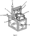
Figure 2 is a general scheme of the various parts of the device according to the present invention. -
Figure 3 is a general scheme of the dynamic actuator (14). -
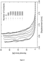
Figure 4 shows the series of force vs displacement curves recorded successively during the wear test of Sample A. -
Figure 5 shows the correlation between the shift in the force vs displacement curves (obtained from the curves ofFigure 4 ) and the weight loss along wear tests. -
Figure 6 show the results of the optical measurement of the change in sample thickness and the weight loss as directly measured for Sample A in example 1. -
Figure 7 shows the results in the wear detection as evaluated according to example 1 for Sample A and Sample B. - A first object of the present invention is a device for testing wear and friction properties of materials comprising:
- a rotating disk (5) fixed to a vertical shaft (6) driven by a first motor (16),
- a friction surface (17) provided on the rotating disk (5),
- a sample holder (10) for holding a sample surface in contact with the friction surface (17),
- means for providing for intermittent engagement of a sample surface with the friction surface and for measuring the forces applied during said intermittent engagement, said means comprising a dynamic actuator (14) and a three axes load cell (2) connected with the sample holder (10), the device being characterized in that it further comprises:
- a camera (4) independent from the movement of the sample holder for detecting wear,
- a data acquisition system connected to the outputs of the camera (4) and the three axis load cell (2) for the evaluation of wear and friction properties of samples, and configured so that at chosen intervals during the wear tests, normal force vs displacement curves in static indentation, that is to say with no sliding velocity, by suppressing temporarily the disk (5) rotation, are recorded, and so that the shift of the force vs displacement curves along a test is evaluated, which is directly related to the change in thickness of the sample, that is, to the loss of matter, which can then be expressed in terms of weight loss, and
wherein - the dynamic actuator (14), the sample holder and the three axis load cell are mounted on a drive system providing for horizontal and vertical displacement with respect to the rotating disk, said system comprising a mechanical support (8) driven horizontally by a second motor (13) and a vertical support (1) mounted onto said mechanical support (8) for movement therewith, which is driven vertically by a third motor (12), and wherein first motor (16), second motor (13) and third motor (12) are driven independently one of the other.
- Referring now in details to
Figures 1 to 3 , the device of the present invention comprises a rotating disk (5) fixed to a vertical shaft (6) driven by a first motor (16). The rotating disk can easily be removed by lifting it out of the shaft. - The independent motion of the rotating disk along shaft (6) driven by the first motor (16) provides for a large range of sliding velocities.
- The preferred sliding velocity is comparable to what a tire experiences in service, and it is more preferably varied from 0.001 to 1 m/s, typically from 0.005 to 0.50 m/s preferably from 0.01 to 0.10 m/s.
- A speed reduction gear box is mounted on the shaft to obtain a large enough torque, so that rotating speed is not affected by the friction during contacts of the sample.
- Rotating disks having different thickness and diameter can be used. The rotating disk may have a thickness of from 1.0 to 5.0 cm, typically of from 1.0 to 4.0 cm. The rotating disk may have a diameter of from 15 to 50 cm, typically of 15 to 45 cm, preferably of from 20 to 40 cm.
- In a preferred embodiment, a rotating disk with a thickness of 1.0 to 3.0 cm and a diameter of 25 to 35 cm is used. Good results have been obtained with a rotating disk with a thickness of 2.0 cm and a diameter of 30 cm.
- A rotating disk with a friction surface of any nature and roughness can be used. The friction surface (17) may be any one of a variety of different surfaces. Preferably, the friction surface is made of polished stain steel, granite, glass or sand paper.
- The friction surface may have different textures, for example rough, smooth, grooved, etc. The friction surface texture can be tuned depending on the desired test conditions or test severity.
- The friction surface can be removably supported on the rotating disk or representing the surface of the rotating disk itself. The friction surface can be easily interchanged with other friction elements of different materials and/or roughness, as may be desired for testing a particular sample on different friction surfaces and/or in different test conditions. Interchanging the surfaces can be achieved by substituting the friction surface supported on the rotating disk or by substituting the whole rotating disk by lifting it out of the shaft (6) and substituting it with a rotating disk bearing a different friction surface.
- The device comprises a mechanical support (8), which is driven horizontally by a second motor (13).
- The mechanical support (8) has mounted thereon a vertical support (1) which moves therewith and is also driven vertically by a third motor (12). The vertical support carries a dynamic actuator (14), a three axes load cell (2) and a sample holder (10) attached to the lower end.
- Motion of the vertical support is constrained to be strictly vertical with a vertical guidance rail (21).
- The regulation of the static sample horizontal and vertical displacements is assured by the movement of the second motor (13) and of the third motor (12), respectively. This ensures that the sample is held in its proper location against the friction surface (17) supported on the rotating disk.
- The regulation of the vertical displacements of the sample determines the normal load (normal force FN) applied to the sample.
- The normal force applied to the sample may be in the range of from 1 to 100 N, preferably in the range from 10 to 50 N, more preferably from 20 to 40 N. Still more preferably, the normal force is of 40 N.
- The second motor (13) provides for the horizontal displacement of the mechanical support and thus of the sample. Horizontal displacement is used to position the sample at a given distance from the shaft (6) axis of the rotating disk (i.e. at a given radius). The horizontal displacement can be varied in real time during the test, thus providing for a contact of the sample with unused parts of the disk friction surface. This ensures that friction and/or wear tests are performed in true "open cycle" conditions.
- The first motor (16), the second motor (13) and the third motor (12) are driven independently one from the other. They are powered through power regulators and/or variators.
- A dynamic actuator (14) controls the vertical dynamical displacement of the sample onto the friction surface, being configured to provide for the intermittent engagement of the sample with the friction surface supported on the rotating disk, assuring a fully independent control of contact time, frequency of contacts and sliding velocity.
- Preferred dynamic actuator (14) is a large amplitude actuator, with amplitude in the order of 1 mm, which allows maximum loading of up to 100 N, with very short response time, in the milliseconds (ms) range. Preferably, the dynamic actuator is a piezo-electric actuator.
- The three axis load cell (2), located on top of the sample holder, measures the forces applied onto the sample over the three axes, giving the values of normal and tangential loadings of the sample over the friction surface in real time. The time resolution of the three axis cell is in the order of 1 kHz.
- The output of the load cell is connected to a data acquisition system.
- In a preferred embodiment, a spacer (20) is placed in between the dynamic actuator (14) and the sample holder (10).
- The sample holder (10) can be of any suitable geometric shape, cylindrical shape being preferred.
- A temperature measurement device (3) is placed in contact with the sample holder in order to measure the actual sample temperature during the test.
- An alignment device (19) mounted on the vertical support (1) ensures to arrange the sample surface and the friction surface in parallel arrangement, or so that a fixed angle is formed between them. Preferably, the alignment device is made of a clamped spherical fixture.
- The angle between the sample surface and the friction surface may advantageously be comprised between 0 and ±10°, typically between 0 and ±5° .
- The sample deformation is measured in-situ with a camera (4), by realtime absolute measurements of the distance between the sample and the friction surface.
- The camera is placed in horizontal position onto the device and independent from the movement of the sample. It is maintained at a constant distance to the sample.
- The camera may be an optical or digital camera. The camera is preferably a high resolution digital optical In a preferred embodiment, the camera is mounted on the mechanical support (8), for movement therewith.
- The camera allows high resolution visualization of the sample throughout the test and dynamical, real time recording of the sample deformation during each contact.
- The thickness of the sample submitted to wear is measured in real time during the wear test with micrometer accuracy. Any drift of the measured vertical displacement at a fixed force level is related to the change in the thickness of the sample, that is, to the amount of matter lost during the test, which can then be expressed in terms of weight loss. Thus, advantageously the inventive device allows determining the wear, i.e. weight loss, of the sample in-situ without the need to remove the sample from the device and determine its weight. The wear of the sample can be monitored throughout the performance test.
- In a preferred embodiment, a light source (9) is placed in background, behind the sample, in front of the camera, to create high contrast for optical visualization.
- The optical camera may also be used to determine the exact vertical sample position, and to adjust the vertical position of the sample close to the disk surface.
- The device can be enclosed in a temperature controlled chamber to simulate different temperature and environmental conditions (e.g. humidity ratio), such as winter and summer conditions, and to evaluate the effects of temperature variations on the sample.
- The temperature surrounding the device can be regulated in the range comprised between 0 and 80°C, preferably in the range comprised between 20 and 60°C, by means of a suitable heating and/or cooling unit (7).
- In a preferred embodiment of the invention, the device includes a temperature control chamber (15) enclosing at least the friction surface and the sample holder, when the device is not in use, and the sample holder and the sample, when the device is in use. In a further preferred embodiment, the temperature control chamber further encloses the heating and/or cooling unit (7).
- The top wall of the chamber can be opened by means of a handle. This enables easy and quick interchanging of samples, rotating disks and friction surfaces.
- The device includes an appropriate way to clean the friction surface, that is, to eliminate wear debris from the friction surface.
- In a preferred embodiment of the invention, a processor controls all the operations, parameter settings and data acquisition: static sample horizontal and vertical displacements; disk rotation; control of the normal load; signal triggering; control of the dynamical displacement; data acquisition.
- The processor further analyses the data and provides a readout of the results, preferably in the form of tables and/or graphs.
- A second object of the present invention is an assembly comprising the aforesaid device and a sample (11) of a material. The sample is placed in the sample holder (10). Sample (11) is attached to the sample holder (10) so that the surface of the sample to be tested is available for contact with the friction surface (17) of the rotating disk (5).
- The sample (11) can be of any geometrical shape which fits in the sample holder. Preferably, the sample is in the form of a cylinder, a hemisphere or a sheet.
- The sample (11) is removably attached to the sample holder by suitable means.
- Preferably, the thickness of the sample is of from 1 to 5 mm, more preferably it is of about 2 mm.
- In a preferred embodiment, the sample is an elastomer sample of cylindrical shape having diameter in the range comprised between 5 and 10 mm and thickness of about 2 mm.
- In another preferred embodiment, an elastomer sample has a hemispherical shape of preferred radius between 5 and 10 cm.
- In another preferred embodiment, the sample is a sheet of elastomer of
thickness 2 mm. In this preferred embodiment the sheet of elastomer is adjusted on a cylinder with axis parallel to the friction surface of preferred radius between 5 and 10 cm, said cylinder being then removably attached to the sample holder. - In the present specification, the term elastomer is used in the meaning provided by IUPAC to indicate a "polymer that displays rubber-like elasticity", that is a polymer which readily undergoes deformation and exhibits large reversible elongations under small applied stress. Elastomer (E) preferably exhibits at least one glass transition temperature (Tg), measured by differential scanning calorimetry (DSC) of between -150°C and +300°C, for example between -150°C and +20°C.
- A further object of the present invention consists in providing a method of testing wear and friction properties of a sample by using the aforesaid device.
- The method comprises the steps of: preparing a sample (11); attaching the sample to the sample holder (10); selecting the rotating disk (5) or the friction surface (17) to be supported onto the rotating disk (5); activating the first motor (16) for setting the disk rotation speed; activating the second motor (13) and the third motor (12) to set the horizontal and vertical position of the sample (11) on the friction surface (17); activating the dynamic actuator (14) to apply the normal load (normal force) onto the sample and to provide intermittent engagement of sample (11) with friction surface (17); and recording the outputs of the three axis load cell (2) and of the camera (4) for the evaluation of parameters related to wear and friction properties of samples, wherein at chosen intervals during the test, normal force vs displacement curves in static indentation, that is to say with no sliding velocity, by suppressing temporarily the disk (5) rotation, are recorded, wherein the normal force variation is measured by the three axis load cell (2) and the displacement is measured with the camera (4), then the shift of the force vs displacement curves along the test is evaluated, which is directly related to the change in thickness of the sample (11), that is, to the loss of matter, which can then be expressed in terms of weight loss.
- The method includes in-situ measurements of the sample thickness by performing force vs displacement curves in static indentation (no sliding velocity, by suppressing temporarily the disk rotation) at chosen intervals during the wear tests, wherein the normal force variation is measured by the three axis load sensor and the displacement is measured with the high resolution camera.
- The duration of the test is comprised between 1 and 20 hours, preferably between 1 and 10 hours, more preferably between 2 and 5 hours.
- In a preferred embodiment, the method of the present invention further comprises the step of replacing the friction surface with another different friction surface to predict sample characteristics with respect to different surfaces.
- The method is preferably performed in the absence of any abrasive slurry or lubricant, or in general of any liquid, between the samples surface and the friction surface on the rotating disk.
- In a preferred embodiment, the method comprises regulating the temperature in the range comprised between 0 and 80°C, preferably between 20 and 60°C.
- In a preferred embodiment, the present invention provides a method for predicting tire wear and friction properties of a tread component.
- At each contact of the sample with the surface of the friction surface the outputs of the camera, of the three axis load cell and of the temperature sensor are acquired. In particular the following parameters are measured and acquired by the system:
- the sample thickness,
- the sample displacement over three axes,
- the forces over the three axes, and
- the sample temperature.
- The outputs are connected to a data acquisition system for the evaluation of several parameters related to wear and friction properties of samples:
- tangential load as a function of normal load in real time: FT=f(FN);
- time evolution of normal and tangential loads and friction coefficient: µ=f(t);
- displacement, normal and tangential forces during one contact.
- At chosen intervals during the wear tests, normal force vs displacement curves in static indentation (no sliding velocity, by suppressing temporarily the disk rotation) are recorded: the normal force variation is measured by the three axis load sensor and the displacement is measured with the high resolution camera.
- The shift of the force vs displacement curves along a test is then evaluated, which is directly related to the change in thickness of the sample, that is, to the loss of matter, which can then be expressed in terms of weight loss.
- Wear measurement are expressed as weight loss per unit slipping length per unit area of contact, computed as w = hAd/1000, where w is the weight loss value (in mg), h is the average vertical change (change in thickness of the sample, in µm), A is the contact surface area (in mm2) and d is the density of the material (in g/cm3).
- Thus, advantageously the inventive method allows determining the wear, i.e. weight loss, of the sample in-situ without the need to remove the sample from the device and determine its weight.
- Slipping length per contact is defined as the sliding velocity (given by the rotation speed of the disk multiplied by the distance between the sample and the axis of the rotating disk) multiplied by the sliding contact duration.
- Contact area is preferably between 10 and 100 mm2.
- The friction coefficient is calculated as the ratio of the tangential load FT over the normal load FN.
- The advantages offered by the proposed method of testing wear and friction properties of a sample when contacted with a friction surface include, among others, the short duration of the test and the possibility of evaluating wear and friction properties under different temperature conditions. The independent movement of motors for sample displacement and rotating disk advantageously allows changing separately and independently the sliding velocity, the dynamic loading conditions and the contact time between the sample and the friction surface. This allows easily evaluating the wear in different severity conditions.
- Moreover, the easy interchanging of friction surfaces and of samples allows the fast evaluation of the wear and friction properties of series of samples contacted to different friction surface.
- The term "independent" is used to refer to a motor which is not in mechanical connection with other motors, and can thus be driven without any relation to other motor's movements.
- The term "intermittent engagement" as used herein refers to the contact between the sample and the friction surface which occurs discontinuously over time, with a specific frequency and duration of contact.
- The work leading to this invention has received funding from the European Union Seventh Framework Programme ([FP7/2007-2013] under grant agreement n° 314463.
- The following examples illustrate the invention without, however, limiting the scope thereof.
- Two rubber compositions (A and B) were prepared in a 10.380 liter Haake like internal mixer and vulcanized at 150°C. The composition of samples A and B, expressed as parts by weight per 100 parts of elastomers (phr), is shown in Table I below.
Table I Composition A B NR (1) 100 100 Silica (2) - 55 Carbon black (3) 50 - Coupling agent (4) 4.4 Antioxidant (5) 1.5 1.5 Antioxidant (6) 1 1 Carbon black (7) 3 3 ZnO 3 3 Stearic acid 2.5 2.5 CBS (8) 0.8 1.9 Sulfur 1.5 1.5 Accelerator (9) 0.2 0.2 (1) Natural Rubber SVR CV 60, available from Weber&Schaer;
(2) Silica Zeosil®1165 MP from Solvay with specific surface BET of 156 m2/g and CTAB of 154 m2/g;
(3) Carbon Black N121, from available Orion;
(4) bis [3-triethoxysilylpropyl] tetrasulfane, commercially available as LUXOMAXX TESPT from Lehmann&Voss&Co;
(5) N-(1,3-Dimethylbutyl)-N-phenyl-para-phenylenediamine, commercially available as Vulkanox 4020/LG 6-PPD from Lanxess;
(6) 2,2,4-trimethyl 1,2-dihydroquinoline, commercially available as Acétonanile TMQ from SMPC;
(7) Carbon Black N330, available from Orion;
(8) CBS N-cyclohexyl-2-benzothiazyl-sulfénamide, commercially available as Rhénogran CBS-80 from RheinChemie;
(9) TBzTD tetrabenzylthiuram disulfide, commercially available as Rhenogran TBzTD-70 from RheinChemie. - Cylindrical shape samples of 10 mm and 18 mm in diameter and 2 mm thick were prepared, respectively, from compositions A and B.
- Samples A and B exhibit similar Shore A hardness, as calculated according to ISO norm ASTM D 2240. The values given after 3 s are of 68 for Sample A and of 67 for Sample B.
- Samples A and B were tested in the device of the invention set as in Table II:
Table II Control parameter Notation and value Sliding velocity (V) V = 5 cm/s Average normal load at contact (Normal force FN) FN = 30 N Estimated average pressure (p) (estimated contact p = FN /A = 0. 35 MPa Contact time (tc) tc = 1 s Time interval between contacts 0.1 s Temperature 24 °C Total number of disk revolutions about 300 Total number of contacts (N) N = 3500 Total test duration about 2 hours - A rotating disk with a friction surface of polished stainless steel was used.
- Wear wastes were eliminated from the contact zone in between two successive contacts by cleaning the disk surface with cleaning tissue applied on the disk surface. Additionally, every 500 contacts, the disk was thoroughly cleaned by using a rubber eraser and the surface of the sample was washed with acetone.
- The change in the thickness of the samples was recorded and force vs displacement curves in static conditions, e.g. by suppressing disk rotation, were recorded at 0, 500, 1000, 1500, 2000, 2500, 3000 and 3500 number of contacts for Samples A and B.
- In
Figure 4 the force vs displacement curves recorded for Sample A are reported. - The relative shift of each curve indicates and quantifies the change in sample thickness.
- The shift in the force vs displacement curves is then correlated with the weight loss along wear tests.
- In
Figure 5 the correlation of the shift in the force vs displacement curves with the directly measured weight loss (Δ weight, mg) is reported. - The results of the optical measurement of the change in sample thickness and the correlation to the directly measured weight loss as are reported in
Figure 6 for Sample A. - The wear performance of different samples can be discriminated as shown in
Figure 7 . - The results demonstrate the reliability of the wear measurement method of the invention, which gives computed values of weight loss that reflects those obtained by direct weight loss measurements.
- The device according to the invention achieves advantages in enabling a quick and reliable evaluation of wear and friction coefficient without the need for direct and time-consuming weight measurements.
Claims (15)
- A device for testing wear and friction properties of materials comprising:- a rotating disk (5) fixed to a vertical shaft (6) driven by a first motor (16),- a friction surface (17) provided on the rotating disk (5),- a sample holder (10) for holding a sample surface in contact with the friction surface (17),- means for providing for intermittent engagement of a sample surface with the friction surface and for measuring the forces applied during said intermittent engagement, said means comprising a dynamic actuator (14) and a three axes load cell (2) connected with the sample holder (10), the device being characterized in that it further comprises:- a camera (4) independent from the movement of the sample holder for detecting wear,- a data acquisition system connected to the outputs of the camera (4) and the three axis load cell (2) for the evaluation of wear and friction properties of samples, and configured so that at chosen intervals during the wear tests, normal force vs displacement curves in static indentation, that is to say with no sliding velocity, by suppressing temporarily the disk (5) rotation, are recorded, and so that the shift of the force vs displacement curves along a test is evaluated, which is directly related to the change in thickness of the sample, that is, to the loss of matter, which can then be expressed in terms of weight loss, and
wherein- the dynamic actuator (14), the sample holder (10) and the three axis load cell (2) are mounted on a drive system providing for horizontal and vertical displacement with respect to the rotating disk (5), said system comprising a mechanical support (8) driven horizontally by a second motor (13) and a vertical support (1) mounted onto said mechanical support (8) for movement therewith, which is driven vertically by a third motor (12), and wherein first motor (16), second motor (13) and third motor (12) are driven independently one of the other. - The device according to claim 1 wherein the angle between the sample surface and the friction surface is comprised between 0 and ±10°, preferably between 0 and ±5° , especially 0°.
- The device according to any one of the preceding claims wherein the friction surface (17) is selected from the group consisting of polished stain steel, granite, glass and sand paper.
- The device according to any one of the preceding claims wherein the dynamic actuator (14) is a piezo-electric actuator.
- The device according to any one of the preceding claims wherein the camera (4) is mounted on the mechanical support (8).
- The device according to any one of the preceding claims further including a heating and/or cooling unit (7) for regulating the temperature surrounding the device in the range comprised between 0 and 80° C, preferably in the range comprised between 20 and 60° C.
- The device according to any one of the preceding claims further including a temperature control chamber (15) enclosing at least friction surface (17), sample holder (10) and heating and/or cooling unit (7).
- The device according to any one of the preceding claims further including a temperature measurement device (3) placed in contact with the sample holder (10).
- The device according to any one of claims 1 to 7 further including a temperature sensor for measuring the sample temperature and a data acquisition system to which the outputs of the camera (4), of the three axis load cell (2) and of the temperature sensor are connected.
- An assembly comprising the device of any one of claims 1 to 9 and a sample (11) attached to the sample holder (10).
- A method of testing wear and friction properties of samples using the device of any one of claims 1 to 9, said method comprising the steps of: preparing a sample (11); attaching sample (11) to sample holder (10); selecting the rotating disk (5) or the friction surface (17) to be supported onto the rotating disk (5); activating first motor (16) for setting of the disk rotation speed; activating second motor (13) and third motor (12) to set the horizontal and vertical position of sample (11) on friction surface (17); activating dynamic actuator (14) to apply a normal load onto sample (11) and to provide for intermittent engagement of sample (11) with friction surface (17); and recording the outputs of the three axis load cell (2) and of camera (4) for the evaluation of parameters related to wear and friction properties of samples,
whereinat chosen intervals during the test, normal force vs displacement curves in static indentation, that is to say with no sliding velocity, by suppressing temporarily the disk (5) rotation, are recorded, wherein the normal force variation is measured by the three axis load cell (2) and the displacement is measured with the camera (4),then the shift of the force vs displacement curves along the test is evaluated, which is directly related to the change in thickness of the sample (11), that is, to the loss of matter, which can then be expressed in terms of weight loss. - The method of claim 11 characterized in that the duration of the test is comprised between 1 and 20 hours, preferably between 1 and 10 hours, more preferably between 2 and 5 hours.
- The method according to claim 11 or 12 which further comprises regulating the temperature surrounding the device in the range from 0 to 80° C, preferably from 20 to 80°C.
- The method according to any one of claims 11 to 13 wherein the horizontal displacement is changed in real time during the test.
- The method according to any one of claims 11 to 14 which uses the device according to claim 9 and wherein the sample thickness, the sample displacement over three axes, the forces over the three axes and the sample temperature are measured and acquired by the data acquisition system.
Applications Claiming Priority (2)
| Application Number | Priority Date | Filing Date | Title |
|---|---|---|---|
| EP16306165 | 2016-09-14 | ||
| PCT/EP2017/072440 WO2018050531A1 (en) | 2016-09-14 | 2017-09-07 | Device for measuring rubber wear |
Publications (2)
| Publication Number | Publication Date |
|---|---|
| EP3513164A1 EP3513164A1 (en) | 2019-07-24 |
| EP3513164B1 true EP3513164B1 (en) | 2025-05-14 |
Family
ID=56997436
Family Applications (1)
| Application Number | Title | Priority Date | Filing Date |
|---|---|---|---|
| EP17761288.4A Active EP3513164B1 (en) | 2016-09-14 | 2017-09-07 | Device for measuring rubber wear |
Country Status (6)
| Country | Link |
|---|---|
| US (1) | US11067489B2 (en) |
| EP (1) | EP3513164B1 (en) |
| JP (1) | JP7018938B2 (en) |
| KR (1) | KR102396601B1 (en) |
| CN (1) | CN109690282B (en) |
| WO (1) | WO2018050531A1 (en) |
Families Citing this family (27)
| Publication number | Priority date | Publication date | Assignee | Title |
|---|---|---|---|---|
| US11435244B2 (en) * | 2017-11-30 | 2022-09-06 | Koc Universitesi | Force sensor for measuring static and dynamic friction coefficients |
| CN109506906B (en) * | 2018-11-04 | 2024-12-10 | 江苏兴达钢帘线股份有限公司 | Friction disc failure test device |
| CN109612853B (en) * | 2018-11-26 | 2021-08-03 | Tcl华星光电技术有限公司 | Compression test device and test method thereof |
| JP7138025B2 (en) * | 2018-11-28 | 2022-09-15 | Toyo Tire株式会社 | Rubber adhesion test method and rubber adhesion test system |
| CN109632550B (en) * | 2018-12-24 | 2022-01-14 | 长安大学 | Abrasion performance contrast test device and test method |
| TR201902951A2 (en) * | 2019-02-27 | 2020-09-21 | Ege Ueniversitesi Rektoerluegue | Fabric Flatness Measurement Device |
| EP3754331A1 (en) * | 2019-06-20 | 2020-12-23 | GrindoSonic BVBA | Method and system for analysing a test piece using a vibrational response signal |
| CN110567832A (en) * | 2019-10-17 | 2019-12-13 | 大冶市飞亚模具材料有限公司 | Die steel wear resistance test device |
| KR102294798B1 (en) * | 2019-12-26 | 2021-08-30 | 한국세라믹기술원 | Fine dust detection and analysis device |
| CN111426456B (en) * | 2020-01-17 | 2021-11-26 | 北京工业大学 | Steel rubber roller pair rolling test bed |
| CN112098253A (en) * | 2020-09-21 | 2020-12-18 | 中通服咨询设计研究院有限公司 | Indoor concrete ice abrasion testing device and testing method |
| CN112621606A (en) * | 2020-12-11 | 2021-04-09 | 河北省产品质量监督检验研究院 | Device for measuring sliding friction coefficient between two objects |
| KR102549783B1 (en) * | 2021-06-22 | 2023-06-30 | 한국생산기술연구원 | Method for Calculating Friction Coefficient for Each Process through Quantitative Evaluation of Phosphate Coat |
| CN114323913B (en) * | 2021-12-13 | 2024-05-31 | 中北大学 | Tread rubber friction and wear testing device and method for simulating service conditions of tank road wheels |
| CN114295507B (en) * | 2021-12-29 | 2025-01-24 | 青岛海诺泰科检测仪器有限公司 | Rubber high temperature multi-angle abrasion testing machine |
| CN115165650B (en) * | 2022-08-22 | 2023-07-28 | 郑州天源橡胶有限公司 | Intelligent detection equipment for high polymer rubber products |
| CN115753474B (en) * | 2022-11-24 | 2025-12-16 | 长安大学 | Indoor evaluation device and evaluation method for polishing resistance of pavement material |
| KR102585113B1 (en) * | 2023-02-28 | 2023-10-04 | 김진표 | A physical property analyzer capable of measuring the friction coefficient of soft objects |
| CN116429624B (en) * | 2023-05-06 | 2025-11-28 | 上海交通大学 | Intelligent measurement and control system and method for friction and wear testing machine of typical kinematic pair of aviation tail nozzle |
| CN117347254A (en) * | 2023-09-06 | 2024-01-05 | 中国科学院宁波材料技术与工程研究所 | A tribochemical in-situ characterization device and its application |
| GB2638795A (en) * | 2023-09-06 | 2025-09-03 | Ningbo Institute Of Materials Tech And Engineering Of The Chinese Academy Of Sciences | Friction chemical in-situ characterization apparatus and use thereof |
| CN118111904B (en) * | 2024-03-11 | 2025-08-19 | 哈尔滨工业大学 | Friction lubrication characteristic testing device and method for simulating non-transparent material matching pair |
| KR102717420B1 (en) * | 2024-04-18 | 2024-10-16 | 한국지질자원연구원 | Micro particle erosion tester |
| CN118424936B (en) * | 2024-07-01 | 2024-11-15 | 江苏唐盛纺织科技有限公司 | Method and device for testing dry-wet wear resistance of textile product |
| CN119043976B (en) * | 2024-10-30 | 2025-04-04 | 东莞市明亮应用材料科技有限公司 | Silica gel reflecting material wear resistance testing device and method |
| CN119845967B (en) * | 2025-01-09 | 2026-02-03 | 武汉纺织大学 | Textile fabric printing and dyeing detection equipment and detection method |
| CN120253545B (en) * | 2025-05-30 | 2025-08-26 | 德州恒力电机有限责任公司 | Device for detecting working state of wear-resistant coating of electromagnetic brake |
Family Cites Families (24)
| Publication number | Priority date | Publication date | Assignee | Title |
|---|---|---|---|---|
| JPH02102433A (en) | 1988-10-11 | 1990-04-16 | Sutaaraito Kogyo Kk | Pin disk type wear testing instrument |
| JP2850054B2 (en) * | 1990-12-12 | 1999-01-27 | 横浜ゴム株式会社 | Friction testing machine |
| JPH06208017A (en) * | 1993-01-11 | 1994-07-26 | Sony Corp | Color filter defect inspection method and defect inspection apparatus |
| US6349587B1 (en) * | 1997-04-07 | 2002-02-26 | Bridgestone/Firestone Research, Inc. | Portable universal friction testing machine and method |
| JPH10300657A (en) * | 1997-04-25 | 1998-11-13 | Mitsubishi Electric Corp | Elevator emergency stop friction characteristics test apparatus and test method |
| JP3320653B2 (en) * | 1998-05-08 | 2002-09-03 | 株式会社ブリヂストン | Tire wear life prediction method |
| US6412330B1 (en) * | 1998-11-25 | 2002-07-02 | The Goodyear Tire & Rubber Company | Abrasion tester |
| US6494765B2 (en) | 2000-09-25 | 2002-12-17 | Center For Tribology, Inc. | Method and apparatus for controlled polishing |
| JP3595318B2 (en) * | 2002-05-31 | 2004-12-02 | 神鋼造機株式会社 | Friction and wear test equipment |
| JP4594213B2 (en) * | 2005-11-04 | 2010-12-08 | 株式会社ブリヂストン | Method for measuring friction coefficient of elastic body |
| JP5035991B2 (en) | 2008-02-21 | 2012-09-26 | 株式会社ブリヂストン | Rubber testing machine |
| US9134214B2 (en) | 2008-02-29 | 2015-09-15 | Juozas Padgurskas | Device for measuring the influence of friction force on wear characteristics of a material surface with high frequency loading force |
| JP5363965B2 (en) * | 2009-12-17 | 2013-12-11 | 日東精工株式会社 | Screw parts tightening device |
| JP5534587B2 (en) * | 2010-02-04 | 2014-07-02 | 株式会社ブリヂストン | Rubber testing machine |
| JP2011209187A (en) * | 2010-03-30 | 2011-10-20 | Railway Technical Research Institute | Wear volume measuring device |
| US9581534B2 (en) * | 2010-07-09 | 2017-02-28 | Tribis Engineering, Inc. | Tribometer |
| US8371182B1 (en) * | 2012-06-11 | 2013-02-12 | Jacob Israelachvili | Mounting systems for a surface forces apparatus |
| CN102944512B (en) * | 2012-11-03 | 2016-09-21 | 中国矿业大学 | The end-surface twisting friction-wear testing machine of a kind of Real-time and Dynamic observation frictional interface and method |
| CN203132516U (en) * | 2013-03-01 | 2013-08-14 | 中国兵器科学研究院 | Wear life real-time prediction device |
| CN104198370B (en) * | 2014-09-19 | 2016-10-05 | 四川大学 | Slide rolling friction performance experiment table intelligent observing and controlling system |
| CN104297089A (en) * | 2014-10-15 | 2015-01-21 | 中国矿业大学 | Microcosmic frictional wear performance testing device |
| JP6394295B2 (en) * | 2014-11-06 | 2018-09-26 | 横浜ゴム株式会社 | Wear test apparatus and method |
| CN104708726B (en) * | 2015-04-02 | 2016-08-24 | 沈阳华夏光微电子装备有限责任公司 | A kind of real-time monitoring tool temperature and the scribing machine of wear intensity and control method |
| US20180292465A1 (en) * | 2017-04-07 | 2018-10-11 | Board Of Regents, The University Of Texas System | Systems and methods for degradation analysis |
-
2017
- 2017-09-07 JP JP2019513936A patent/JP7018938B2/en active Active
- 2017-09-07 EP EP17761288.4A patent/EP3513164B1/en active Active
- 2017-09-07 KR KR1020197010242A patent/KR102396601B1/en active Active
- 2017-09-07 CN CN201780056565.3A patent/CN109690282B/en active Active
- 2017-09-07 US US16/333,216 patent/US11067489B2/en active Active
- 2017-09-07 WO PCT/EP2017/072440 patent/WO2018050531A1/en not_active Ceased
Also Published As
| Publication number | Publication date |
|---|---|
| JP2019529903A (en) | 2019-10-17 |
| CN109690282B (en) | 2024-01-09 |
| CN109690282A (en) | 2019-04-26 |
| US20190242800A1 (en) | 2019-08-08 |
| KR20190053885A (en) | 2019-05-20 |
| KR102396601B1 (en) | 2022-05-12 |
| US11067489B2 (en) | 2021-07-20 |
| EP3513164A1 (en) | 2019-07-24 |
| JP7018938B2 (en) | 2022-02-14 |
| WO2018050531A1 (en) | 2018-03-22 |
Similar Documents
| Publication | Publication Date | Title |
|---|---|---|
| US11067489B2 (en) | Device for measuring rubber wear | |
| CN104677763B (en) | Rubber wet grinding grain-abrasion testing machine | |
| US6494765B2 (en) | Method and apparatus for controlled polishing | |
| US6412330B1 (en) | Abrasion tester | |
| KR101680749B1 (en) | Polishing apparatus | |
| CN201133893Y (en) | Multifunctional material surface behaviour tester | |
| US7614275B2 (en) | Method and apparatus for determining coefficient of friction | |
| CN108169047B (en) | Friction and wear testing machine for testing film materials | |
| CN204405466U (en) | Rubber wet-milling grain-abrasion testing machine | |
| KR100515395B1 (en) | Precision Friction Tester | |
| CN108548776B (en) | Rubber material surface friction performance testing device | |
| US20090158826A1 (en) | Material testing apparatus with non-contact sensor | |
| CN107271306A (en) | It is a kind of to carry drawing, the friction-wear detecting apparatus of press mechanism and method of testing | |
| JP5035991B2 (en) | Rubber testing machine | |
| CN109827899B (en) | Material surface property tester | |
| JP2008185475A (en) | Rubber abrasion tester, and abrasion testing method of rubber for tire tread using it | |
| JP5534587B2 (en) | Rubber testing machine | |
| CN110900356B (en) | On-line detection device and method for friction characteristics of polishing disc surface in full-diameter polishing | |
| Pan et al. | Recent patents on friction and wear tester | |
| US6250142B1 (en) | Waviness measurement | |
| CN108169048A (en) | A kind of novel friction abrasion tester of film | |
| CN208012990U (en) | A kind of novel friction abrasion tester of film | |
| CN112129532B (en) | Porous sliding bearing comprehensive performance test bed and test method thereof | |
| JP4074215B2 (en) | Friction test equipment | |
| RU2841057C1 (en) | Experimental stand for testing vacuum suction cups of various structures and materials for torsion in various media |
Legal Events
| Date | Code | Title | Description |
|---|---|---|---|
| STAA | Information on the status of an ep patent application or granted ep patent |
Free format text: STATUS: UNKNOWN |
|
| STAA | Information on the status of an ep patent application or granted ep patent |
Free format text: STATUS: THE INTERNATIONAL PUBLICATION HAS BEEN MADE |
|
| PUAI | Public reference made under article 153(3) epc to a published international application that has entered the european phase |
Free format text: ORIGINAL CODE: 0009012 |
|
| STAA | Information on the status of an ep patent application or granted ep patent |
Free format text: STATUS: REQUEST FOR EXAMINATION WAS MADE |
|
| 17P | Request for examination filed |
Effective date: 20190415 |
|
| AK | Designated contracting states |
Kind code of ref document: A1 Designated state(s): AL AT BE BG CH CY CZ DE DK EE ES FI FR GB GR HR HU IE IS IT LI LT LU LV MC MK MT NL NO PL PT RO RS SE SI SK SM TR |
|
| AX | Request for extension of the european patent |
Extension state: BA ME |
|
| DAV | Request for validation of the european patent (deleted) | ||
| DAX | Request for extension of the european patent (deleted) | ||
| RAP1 | Party data changed (applicant data changed or rights of an application transferred) |
Owner name: CENTRE NATIONAL DE LA RECHERCHE SCIENTIFIQUE Owner name: RHODIA OPERATIONS |
|
| STAA | Information on the status of an ep patent application or granted ep patent |
Free format text: STATUS: EXAMINATION IS IN PROGRESS |
|
| 17Q | First examination report despatched |
Effective date: 20220118 |
|
| RAP3 | Party data changed (applicant data changed or rights of an application transferred) |
Owner name: CENTRE NATIONAL DE LA RECHERCHE SCIENTIFIQUE Owner name: RHODIA OPERATIONS |
|
| GRAP | Despatch of communication of intention to grant a patent |
Free format text: ORIGINAL CODE: EPIDOSNIGR1 |
|
| STAA | Information on the status of an ep patent application or granted ep patent |
Free format text: STATUS: GRANT OF PATENT IS INTENDED |
|
| INTG | Intention to grant announced |
Effective date: 20241213 |
|
| GRAS | Grant fee paid |
Free format text: ORIGINAL CODE: EPIDOSNIGR3 |
|
| GRAA | (expected) grant |
Free format text: ORIGINAL CODE: 0009210 |
|
| STAA | Information on the status of an ep patent application or granted ep patent |
Free format text: STATUS: THE PATENT HAS BEEN GRANTED |
|
| AK | Designated contracting states |
Kind code of ref document: B1 Designated state(s): AL AT BE BG CH CY CZ DE DK EE ES FI FR GB GR HR HU IE IS IT LI LT LU LV MC MK MT NL NO PL PT RO RS SE SI SK SM TR |
|
| P01 | Opt-out of the competence of the unified patent court (upc) registered |
Free format text: CASE NUMBER: APP_17284/2025 Effective date: 20250409 |
|
| REG | Reference to a national code |
Ref country code: GB Ref legal event code: FG4D |
|
| REG | Reference to a national code |
Ref country code: CH Ref legal event code: EP |
|
| REG | Reference to a national code |
Ref country code: DE Ref legal event code: R096 Ref document number: 602017089461 Country of ref document: DE |
|
| REG | Reference to a national code |
Ref country code: IE Ref legal event code: FG4D |
|
| REG | Reference to a national code |
Ref country code: NL Ref legal event code: FP |
|
| PG25 | Lapsed in a contracting state [announced via postgrant information from national office to epo] |
Ref country code: PT Free format text: LAPSE BECAUSE OF FAILURE TO SUBMIT A TRANSLATION OF THE DESCRIPTION OR TO PAY THE FEE WITHIN THE PRESCRIBED TIME-LIMIT Effective date: 20250915 Ref country code: FI Free format text: LAPSE BECAUSE OF FAILURE TO SUBMIT A TRANSLATION OF THE DESCRIPTION OR TO PAY THE FEE WITHIN THE PRESCRIBED TIME-LIMIT Effective date: 20250514 Ref country code: ES Free format text: LAPSE BECAUSE OF FAILURE TO SUBMIT A TRANSLATION OF THE DESCRIPTION OR TO PAY THE FEE WITHIN THE PRESCRIBED TIME-LIMIT Effective date: 20250514 |
|
| PGFP | Annual fee paid to national office [announced via postgrant information from national office to epo] |
Ref country code: DE Payment date: 20250924 Year of fee payment: 9 |
|
| REG | Reference to a national code |
Ref country code: LT Ref legal event code: MG9D |
|
| PG25 | Lapsed in a contracting state [announced via postgrant information from national office to epo] |
Ref country code: GR Free format text: LAPSE BECAUSE OF FAILURE TO SUBMIT A TRANSLATION OF THE DESCRIPTION OR TO PAY THE FEE WITHIN THE PRESCRIBED TIME-LIMIT Effective date: 20250815 Ref country code: NO Free format text: LAPSE BECAUSE OF FAILURE TO SUBMIT A TRANSLATION OF THE DESCRIPTION OR TO PAY THE FEE WITHIN THE PRESCRIBED TIME-LIMIT Effective date: 20250814 |
|
| PG25 | Lapsed in a contracting state [announced via postgrant information from national office to epo] |
Ref country code: PL Free format text: LAPSE BECAUSE OF FAILURE TO SUBMIT A TRANSLATION OF THE DESCRIPTION OR TO PAY THE FEE WITHIN THE PRESCRIBED TIME-LIMIT Effective date: 20250514 |
|
| PGFP | Annual fee paid to national office [announced via postgrant information from national office to epo] |
Ref country code: NL Payment date: 20250922 Year of fee payment: 9 |
|
| REG | Reference to a national code |
Ref country code: AT Ref legal event code: MK05 Ref document number: 1795142 Country of ref document: AT Kind code of ref document: T Effective date: 20250514 |
|
| PG25 | Lapsed in a contracting state [announced via postgrant information from national office to epo] |
Ref country code: BG Free format text: LAPSE BECAUSE OF FAILURE TO SUBMIT A TRANSLATION OF THE DESCRIPTION OR TO PAY THE FEE WITHIN THE PRESCRIBED TIME-LIMIT Effective date: 20250514 |
|
| PGFP | Annual fee paid to national office [announced via postgrant information from national office to epo] |
Ref country code: GB Payment date: 20250923 Year of fee payment: 9 |
|
| PG25 | Lapsed in a contracting state [announced via postgrant information from national office to epo] |
Ref country code: HR Free format text: LAPSE BECAUSE OF FAILURE TO SUBMIT A TRANSLATION OF THE DESCRIPTION OR TO PAY THE FEE WITHIN THE PRESCRIBED TIME-LIMIT Effective date: 20250514 |
|
| PG25 | Lapsed in a contracting state [announced via postgrant information from national office to epo] |
Ref country code: AT Free format text: LAPSE BECAUSE OF FAILURE TO SUBMIT A TRANSLATION OF THE DESCRIPTION OR TO PAY THE FEE WITHIN THE PRESCRIBED TIME-LIMIT Effective date: 20250514 |
|
| PGFP | Annual fee paid to national office [announced via postgrant information from national office to epo] |
Ref country code: FR Payment date: 20250924 Year of fee payment: 9 |
|
| PG25 | Lapsed in a contracting state [announced via postgrant information from national office to epo] |
Ref country code: RS Free format text: LAPSE BECAUSE OF FAILURE TO SUBMIT A TRANSLATION OF THE DESCRIPTION OR TO PAY THE FEE WITHIN THE PRESCRIBED TIME-LIMIT Effective date: 20250814 |
|
| PG25 | Lapsed in a contracting state [announced via postgrant information from national office to epo] |
Ref country code: IS Free format text: LAPSE BECAUSE OF FAILURE TO SUBMIT A TRANSLATION OF THE DESCRIPTION OR TO PAY THE FEE WITHIN THE PRESCRIBED TIME-LIMIT Effective date: 20250914 |
|
| PG25 | Lapsed in a contracting state [announced via postgrant information from national office to epo] |
Ref country code: LV Free format text: LAPSE BECAUSE OF FAILURE TO SUBMIT A TRANSLATION OF THE DESCRIPTION OR TO PAY THE FEE WITHIN THE PRESCRIBED TIME-LIMIT Effective date: 20250514 |
|
| PG25 | Lapsed in a contracting state [announced via postgrant information from national office to epo] |
Ref country code: DK Free format text: LAPSE BECAUSE OF FAILURE TO SUBMIT A TRANSLATION OF THE DESCRIPTION OR TO PAY THE FEE WITHIN THE PRESCRIBED TIME-LIMIT Effective date: 20250514 Ref country code: SM Free format text: LAPSE BECAUSE OF FAILURE TO SUBMIT A TRANSLATION OF THE DESCRIPTION OR TO PAY THE FEE WITHIN THE PRESCRIBED TIME-LIMIT Effective date: 20250514 |
|
| PG25 | Lapsed in a contracting state [announced via postgrant information from national office to epo] |
Ref country code: CZ Free format text: LAPSE BECAUSE OF FAILURE TO SUBMIT A TRANSLATION OF THE DESCRIPTION OR TO PAY THE FEE WITHIN THE PRESCRIBED TIME-LIMIT Effective date: 20250514 |
|
| PG25 | Lapsed in a contracting state [announced via postgrant information from national office to epo] |
Ref country code: EE Free format text: LAPSE BECAUSE OF FAILURE TO SUBMIT A TRANSLATION OF THE DESCRIPTION OR TO PAY THE FEE WITHIN THE PRESCRIBED TIME-LIMIT Effective date: 20250514 |
|
| PG25 | Lapsed in a contracting state [announced via postgrant information from national office to epo] |
Ref country code: SK Free format text: LAPSE BECAUSE OF FAILURE TO SUBMIT A TRANSLATION OF THE DESCRIPTION OR TO PAY THE FEE WITHIN THE PRESCRIBED TIME-LIMIT Effective date: 20250514 Ref country code: RO Free format text: LAPSE BECAUSE OF FAILURE TO SUBMIT A TRANSLATION OF THE DESCRIPTION OR TO PAY THE FEE WITHIN THE PRESCRIBED TIME-LIMIT Effective date: 20250514 |
|
| PG25 | Lapsed in a contracting state [announced via postgrant information from national office to epo] |
Ref country code: IT Free format text: LAPSE BECAUSE OF FAILURE TO SUBMIT A TRANSLATION OF THE DESCRIPTION OR TO PAY THE FEE WITHIN THE PRESCRIBED TIME-LIMIT Effective date: 20250514 |
|
| REG | Reference to a national code |
Ref country code: DE Ref legal event code: R097 Ref document number: 602017089461 Country of ref document: DE |
|
| PLBE | No opposition filed within time limit |
Free format text: ORIGINAL CODE: 0009261 |
|
| STAA | Information on the status of an ep patent application or granted ep patent |
Free format text: STATUS: NO OPPOSITION FILED WITHIN TIME LIMIT |
|
| REG | Reference to a national code |
Ref country code: CH Ref legal event code: L10 Free format text: ST27 STATUS EVENT CODE: U-0-0-L10-L00 (AS PROVIDED BY THE NATIONAL OFFICE) Effective date: 20260325 |
|
| 26N | No opposition filed |
Effective date: 20260217 |
|
| REG | Reference to a national code |
Ref country code: CH Ref legal event code: H13 Free format text: ST27 STATUS EVENT CODE: U-0-0-H10-H13 (AS PROVIDED BY THE NATIONAL OFFICE) Effective date: 20260504 |