EP3512697B1 - Hybridkomposit - Google Patents
Hybridkomposit Download PDFInfo
- Publication number
- EP3512697B1 EP3512697B1 EP17768449.5A EP17768449A EP3512697B1 EP 3512697 B1 EP3512697 B1 EP 3512697B1 EP 17768449 A EP17768449 A EP 17768449A EP 3512697 B1 EP3512697 B1 EP 3512697B1
- Authority
- EP
- European Patent Office
- Prior art keywords
- fibers
- ductile
- hybrid
- hybrid composite
- impact
- Prior art date
- Legal status (The legal status is an assumption and is not a legal conclusion. Google has not performed a legal analysis and makes no representation as to the accuracy of the status listed.)
- Active
Links
Images


Classifications
-
- C—CHEMISTRY; METALLURGY
- C08—ORGANIC MACROMOLECULAR COMPOUNDS; THEIR PREPARATION OR CHEMICAL WORKING-UP; COMPOSITIONS BASED THEREON
- C08J—WORKING-UP; GENERAL PROCESSES OF COMPOUNDING; AFTER-TREATMENT NOT COVERED BY SUBCLASSES C08B, C08C, C08F, C08G or C08H
- C08J5/00—Manufacture of articles or shaped materials containing macromolecular substances
- C08J5/04—Reinforcing macromolecular compounds with loose or coherent fibrous material
- C08J5/047—Reinforcing macromolecular compounds with loose or coherent fibrous material with mixed fibrous material
-
- B—PERFORMING OPERATIONS; TRANSPORTING
- B29—WORKING OF PLASTICS; WORKING OF SUBSTANCES IN A PLASTIC STATE IN GENERAL
- B29C—SHAPING OR JOINING OF PLASTICS; SHAPING OF MATERIAL IN A PLASTIC STATE, NOT OTHERWISE PROVIDED FOR; AFTER-TREATMENT OF THE SHAPED PRODUCTS, e.g. REPAIRING
- B29C70/00—Shaping composites, i.e. plastics material comprising reinforcements, fillers or preformed parts, e.g. inserts
- B29C70/04—Shaping composites, i.e. plastics material comprising reinforcements, fillers or preformed parts, e.g. inserts comprising reinforcements only, e.g. self-reinforcing plastics
- B29C70/06—Fibrous reinforcements only
- B29C70/08—Fibrous reinforcements only comprising combinations of different forms of fibrous reinforcements incorporated in matrix material, forming one or more layers, and with or without non-reinforced layers
-
- B—PERFORMING OPERATIONS; TRANSPORTING
- B29—WORKING OF PLASTICS; WORKING OF SUBSTANCES IN A PLASTIC STATE IN GENERAL
- B29C—SHAPING OR JOINING OF PLASTICS; SHAPING OF MATERIAL IN A PLASTIC STATE, NOT OTHERWISE PROVIDED FOR; AFTER-TREATMENT OF THE SHAPED PRODUCTS, e.g. REPAIRING
- B29C70/00—Shaping composites, i.e. plastics material comprising reinforcements, fillers or preformed parts, e.g. inserts
- B29C70/04—Shaping composites, i.e. plastics material comprising reinforcements, fillers or preformed parts, e.g. inserts comprising reinforcements only, e.g. self-reinforcing plastics
- B29C70/06—Fibrous reinforcements only
- B29C70/10—Fibrous reinforcements only characterised by the structure of fibrous reinforcements, e.g. hollow fibres
- B29C70/16—Fibrous reinforcements only characterised by the structure of fibrous reinforcements, e.g. hollow fibres using fibres of substantial or continuous length
- B29C70/22—Fibrous reinforcements only characterised by the structure of fibrous reinforcements, e.g. hollow fibres using fibres of substantial or continuous length oriented in at least two directions forming a two dimensional structure
- B29C70/226—Fibrous reinforcements only characterised by the structure of fibrous reinforcements, e.g. hollow fibres using fibres of substantial or continuous length oriented in at least two directions forming a two dimensional structure the structure comprising mainly parallel filaments interconnected by a small number of cross threads
-
- B—PERFORMING OPERATIONS; TRANSPORTING
- B32—LAYERED PRODUCTS
- B32B—LAYERED PRODUCTS, i.e. PRODUCTS BUILT-UP OF STRATA OF FLAT OR NON-FLAT, e.g. CELLULAR OR HONEYCOMB, FORM
- B32B1/00—Layered products having a non-planar shape
- B32B1/08—Tubular products
-
- B—PERFORMING OPERATIONS; TRANSPORTING
- B32—LAYERED PRODUCTS
- B32B—LAYERED PRODUCTS, i.e. PRODUCTS BUILT-UP OF STRATA OF FLAT OR NON-FLAT, e.g. CELLULAR OR HONEYCOMB, FORM
- B32B27/00—Layered products comprising a layer of synthetic resin
- B32B27/06—Layered products comprising a layer of synthetic resin as the main or only constituent of a layer, which is next to another layer of the same or of a different material
- B32B27/08—Layered products comprising a layer of synthetic resin as the main or only constituent of a layer, which is next to another layer of the same or of a different material of synthetic resin
-
- B—PERFORMING OPERATIONS; TRANSPORTING
- B32—LAYERED PRODUCTS
- B32B—LAYERED PRODUCTS, i.e. PRODUCTS BUILT-UP OF STRATA OF FLAT OR NON-FLAT, e.g. CELLULAR OR HONEYCOMB, FORM
- B32B27/00—Layered products comprising a layer of synthetic resin
- B32B27/28—Layered products comprising a layer of synthetic resin comprising synthetic resins not wholly covered by any one of the sub-groups B32B27/30 - B32B27/42
- B32B27/281—Layered products comprising a layer of synthetic resin comprising synthetic resins not wholly covered by any one of the sub-groups B32B27/30 - B32B27/42 comprising polyimides
-
- B—PERFORMING OPERATIONS; TRANSPORTING
- B32—LAYERED PRODUCTS
- B32B—LAYERED PRODUCTS, i.e. PRODUCTS BUILT-UP OF STRATA OF FLAT OR NON-FLAT, e.g. CELLULAR OR HONEYCOMB, FORM
- B32B27/00—Layered products comprising a layer of synthetic resin
- B32B27/28—Layered products comprising a layer of synthetic resin comprising synthetic resins not wholly covered by any one of the sub-groups B32B27/30 - B32B27/42
- B32B27/286—Layered products comprising a layer of synthetic resin comprising synthetic resins not wholly covered by any one of the sub-groups B32B27/30 - B32B27/42 comprising polysulphones; polysulfides
-
- B—PERFORMING OPERATIONS; TRANSPORTING
- B32—LAYERED PRODUCTS
- B32B—LAYERED PRODUCTS, i.e. PRODUCTS BUILT-UP OF STRATA OF FLAT OR NON-FLAT, e.g. CELLULAR OR HONEYCOMB, FORM
- B32B27/00—Layered products comprising a layer of synthetic resin
- B32B27/28—Layered products comprising a layer of synthetic resin comprising synthetic resins not wholly covered by any one of the sub-groups B32B27/30 - B32B27/42
- B32B27/288—Layered products comprising a layer of synthetic resin comprising synthetic resins not wholly covered by any one of the sub-groups B32B27/30 - B32B27/42 comprising polyketones
-
- B—PERFORMING OPERATIONS; TRANSPORTING
- B32—LAYERED PRODUCTS
- B32B—LAYERED PRODUCTS, i.e. PRODUCTS BUILT-UP OF STRATA OF FLAT OR NON-FLAT, e.g. CELLULAR OR HONEYCOMB, FORM
- B32B27/00—Layered products comprising a layer of synthetic resin
- B32B27/30—Layered products comprising a layer of synthetic resin comprising vinyl (co)polymers; comprising acrylic (co)polymers
-
- B—PERFORMING OPERATIONS; TRANSPORTING
- B32—LAYERED PRODUCTS
- B32B—LAYERED PRODUCTS, i.e. PRODUCTS BUILT-UP OF STRATA OF FLAT OR NON-FLAT, e.g. CELLULAR OR HONEYCOMB, FORM
- B32B27/00—Layered products comprising a layer of synthetic resin
- B32B27/32—Layered products comprising a layer of synthetic resin comprising polyolefins
-
- B—PERFORMING OPERATIONS; TRANSPORTING
- B32—LAYERED PRODUCTS
- B32B—LAYERED PRODUCTS, i.e. PRODUCTS BUILT-UP OF STRATA OF FLAT OR NON-FLAT, e.g. CELLULAR OR HONEYCOMB, FORM
- B32B27/00—Layered products comprising a layer of synthetic resin
- B32B27/34—Layered products comprising a layer of synthetic resin comprising polyamides
-
- B—PERFORMING OPERATIONS; TRANSPORTING
- B32—LAYERED PRODUCTS
- B32B—LAYERED PRODUCTS, i.e. PRODUCTS BUILT-UP OF STRATA OF FLAT OR NON-FLAT, e.g. CELLULAR OR HONEYCOMB, FORM
- B32B27/00—Layered products comprising a layer of synthetic resin
- B32B27/36—Layered products comprising a layer of synthetic resin comprising polyesters
-
- B—PERFORMING OPERATIONS; TRANSPORTING
- B32—LAYERED PRODUCTS
- B32B—LAYERED PRODUCTS, i.e. PRODUCTS BUILT-UP OF STRATA OF FLAT OR NON-FLAT, e.g. CELLULAR OR HONEYCOMB, FORM
- B32B27/00—Layered products comprising a layer of synthetic resin
- B32B27/38—Layered products comprising a layer of synthetic resin comprising epoxy resins
-
- B—PERFORMING OPERATIONS; TRANSPORTING
- B32—LAYERED PRODUCTS
- B32B—LAYERED PRODUCTS, i.e. PRODUCTS BUILT-UP OF STRATA OF FLAT OR NON-FLAT, e.g. CELLULAR OR HONEYCOMB, FORM
- B32B27/00—Layered products comprising a layer of synthetic resin
- B32B27/40—Layered products comprising a layer of synthetic resin comprising polyurethanes
-
- B—PERFORMING OPERATIONS; TRANSPORTING
- B32—LAYERED PRODUCTS
- B32B—LAYERED PRODUCTS, i.e. PRODUCTS BUILT-UP OF STRATA OF FLAT OR NON-FLAT, e.g. CELLULAR OR HONEYCOMB, FORM
- B32B27/00—Layered products comprising a layer of synthetic resin
- B32B27/42—Layered products comprising a layer of synthetic resin comprising condensation resins of aldehydes, e.g. with phenols, ureas or melamines
-
- B—PERFORMING OPERATIONS; TRANSPORTING
- B32—LAYERED PRODUCTS
- B32B—LAYERED PRODUCTS, i.e. PRODUCTS BUILT-UP OF STRATA OF FLAT OR NON-FLAT, e.g. CELLULAR OR HONEYCOMB, FORM
- B32B5/00—Layered products characterised by the non- homogeneity or physical structure, i.e. comprising a fibrous, filamentary, particulate or foam layer; Layered products characterised by having a layer differing constitutionally or physically in different parts
- B32B5/02—Layered products characterised by the non- homogeneity or physical structure, i.e. comprising a fibrous, filamentary, particulate or foam layer; Layered products characterised by having a layer differing constitutionally or physically in different parts characterised by structural features of a fibrous or filamentary layer
- B32B5/024—Woven fabric
-
- B—PERFORMING OPERATIONS; TRANSPORTING
- B32—LAYERED PRODUCTS
- B32B—LAYERED PRODUCTS, i.e. PRODUCTS BUILT-UP OF STRATA OF FLAT OR NON-FLAT, e.g. CELLULAR OR HONEYCOMB, FORM
- B32B5/00—Layered products characterised by the non- homogeneity or physical structure, i.e. comprising a fibrous, filamentary, particulate or foam layer; Layered products characterised by having a layer differing constitutionally or physically in different parts
- B32B5/02—Layered products characterised by the non- homogeneity or physical structure, i.e. comprising a fibrous, filamentary, particulate or foam layer; Layered products characterised by having a layer differing constitutionally or physically in different parts characterised by structural features of a fibrous or filamentary layer
- B32B5/026—Knitted fabric
-
- B—PERFORMING OPERATIONS; TRANSPORTING
- B32—LAYERED PRODUCTS
- B32B—LAYERED PRODUCTS, i.e. PRODUCTS BUILT-UP OF STRATA OF FLAT OR NON-FLAT, e.g. CELLULAR OR HONEYCOMB, FORM
- B32B5/00—Layered products characterised by the non- homogeneity or physical structure, i.e. comprising a fibrous, filamentary, particulate or foam layer; Layered products characterised by having a layer differing constitutionally or physically in different parts
- B32B5/02—Layered products characterised by the non- homogeneity or physical structure, i.e. comprising a fibrous, filamentary, particulate or foam layer; Layered products characterised by having a layer differing constitutionally or physically in different parts characterised by structural features of a fibrous or filamentary layer
- B32B5/12—Layered products characterised by the non- homogeneity or physical structure, i.e. comprising a fibrous, filamentary, particulate or foam layer; Layered products characterised by having a layer differing constitutionally or physically in different parts characterised by structural features of a fibrous or filamentary layer characterised by the relative arrangement of fibres or filaments of different layers, e.g. the fibres or filaments being parallel or perpendicular to each other
-
- B—PERFORMING OPERATIONS; TRANSPORTING
- B32—LAYERED PRODUCTS
- B32B—LAYERED PRODUCTS, i.e. PRODUCTS BUILT-UP OF STRATA OF FLAT OR NON-FLAT, e.g. CELLULAR OR HONEYCOMB, FORM
- B32B5/00—Layered products characterised by the non- homogeneity or physical structure, i.e. comprising a fibrous, filamentary, particulate or foam layer; Layered products characterised by having a layer differing constitutionally or physically in different parts
- B32B5/22—Layered products characterised by the non- homogeneity or physical structure, i.e. comprising a fibrous, filamentary, particulate or foam layer; Layered products characterised by having a layer differing constitutionally or physically in different parts characterised by the presence of two or more layers which are next to each other and are fibrous, filamentary, formed of particles or foamed
- B32B5/24—Layered products characterised by the non- homogeneity or physical structure, i.e. comprising a fibrous, filamentary, particulate or foam layer; Layered products characterised by having a layer differing constitutionally or physically in different parts characterised by the presence of two or more layers which are next to each other and are fibrous, filamentary, formed of particles or foamed one layer being a fibrous or filamentary layer
- B32B5/26—Layered products characterised by the non- homogeneity or physical structure, i.e. comprising a fibrous, filamentary, particulate or foam layer; Layered products characterised by having a layer differing constitutionally or physically in different parts characterised by the presence of two or more layers which are next to each other and are fibrous, filamentary, formed of particles or foamed one layer being a fibrous or filamentary layer another layer next to it also being fibrous or filamentary
-
- B—PERFORMING OPERATIONS; TRANSPORTING
- B62—LAND VEHICLES FOR TRAVELLING OTHERWISE THAN ON RAILS
- B62K—CYCLES; CYCLE FRAMES; CYCLE STEERING DEVICES; RIDER-OPERATED TERMINAL CONTROLS SPECIALLY ADAPTED FOR CYCLES; CYCLE AXLE SUSPENSIONS; CYCLE SIDE-CARS, FORECARS, OR THE LIKE
- B62K19/00—Cycle frames
- B62K19/02—Cycle frames characterised by material or cross-section of frame members
- B62K19/16—Cycle frames characterised by material or cross-section of frame members the material being wholly or mainly of plastics
-
- B—PERFORMING OPERATIONS; TRANSPORTING
- B62—LAND VEHICLES FOR TRAVELLING OTHERWISE THAN ON RAILS
- B62K—CYCLES; CYCLE FRAMES; CYCLE STEERING DEVICES; RIDER-OPERATED TERMINAL CONTROLS SPECIALLY ADAPTED FOR CYCLES; CYCLE AXLE SUSPENSIONS; CYCLE SIDE-CARS, FORECARS, OR THE LIKE
- B62K21/00—Steering devices
- B62K21/02—Front wheel forks or equivalent, e.g. single tine
-
- C—CHEMISTRY; METALLURGY
- C08—ORGANIC MACROMOLECULAR COMPOUNDS; THEIR PREPARATION OR CHEMICAL WORKING-UP; COMPOSITIONS BASED THEREON
- C08J—WORKING-UP; GENERAL PROCESSES OF COMPOUNDING; AFTER-TREATMENT NOT COVERED BY SUBCLASSES C08B, C08C, C08F, C08G or C08H
- C08J5/00—Manufacture of articles or shaped materials containing macromolecular substances
- C08J5/04—Reinforcing macromolecular compounds with loose or coherent fibrous material
- C08J5/0405—Reinforcing macromolecular compounds with loose or coherent fibrous material with inorganic fibres
- C08J5/041—Reinforcing macromolecular compounds with loose or coherent fibrous material with inorganic fibres with metal fibres
-
- C—CHEMISTRY; METALLURGY
- C08—ORGANIC MACROMOLECULAR COMPOUNDS; THEIR PREPARATION OR CHEMICAL WORKING-UP; COMPOSITIONS BASED THEREON
- C08J—WORKING-UP; GENERAL PROCESSES OF COMPOUNDING; AFTER-TREATMENT NOT COVERED BY SUBCLASSES C08B, C08C, C08F, C08G or C08H
- C08J5/00—Manufacture of articles or shaped materials containing macromolecular substances
- C08J5/04—Reinforcing macromolecular compounds with loose or coherent fibrous material
- C08J5/0405—Reinforcing macromolecular compounds with loose or coherent fibrous material with inorganic fibres
- C08J5/042—Reinforcing macromolecular compounds with loose or coherent fibrous material with inorganic fibres with carbon fibres
-
- C—CHEMISTRY; METALLURGY
- C08—ORGANIC MACROMOLECULAR COMPOUNDS; THEIR PREPARATION OR CHEMICAL WORKING-UP; COMPOSITIONS BASED THEREON
- C08J—WORKING-UP; GENERAL PROCESSES OF COMPOUNDING; AFTER-TREATMENT NOT COVERED BY SUBCLASSES C08B, C08C, C08F, C08G or C08H
- C08J5/00—Manufacture of articles or shaped materials containing macromolecular substances
- C08J5/04—Reinforcing macromolecular compounds with loose or coherent fibrous material
- C08J5/046—Reinforcing macromolecular compounds with loose or coherent fibrous material with synthetic macromolecular fibrous material
-
- B—PERFORMING OPERATIONS; TRANSPORTING
- B29—WORKING OF PLASTICS; WORKING OF SUBSTANCES IN A PLASTIC STATE IN GENERAL
- B29K—INDEXING SCHEME ASSOCIATED WITH SUBCLASSES B29B, B29C OR B29D, RELATING TO MOULDING MATERIALS OR TO MATERIALS FOR MOULDS, REINFORCEMENTS, FILLERS OR PREFORMED PARTS, e.g. INSERTS
- B29K2305/00—Use of metals, their alloys or their compounds, as reinforcement
- B29K2305/08—Transition metals
- B29K2305/12—Iron
-
- B—PERFORMING OPERATIONS; TRANSPORTING
- B29—WORKING OF PLASTICS; WORKING OF SUBSTANCES IN A PLASTIC STATE IN GENERAL
- B29L—INDEXING SCHEME ASSOCIATED WITH SUBCLASS B29C, RELATING TO PARTICULAR ARTICLES
- B29L2031/00—Other particular articles
- B29L2031/30—Vehicles, e.g. ships or aircraft, or body parts thereof
- B29L2031/3091—Bicycles
-
- B—PERFORMING OPERATIONS; TRANSPORTING
- B32—LAYERED PRODUCTS
- B32B—LAYERED PRODUCTS, i.e. PRODUCTS BUILT-UP OF STRATA OF FLAT OR NON-FLAT, e.g. CELLULAR OR HONEYCOMB, FORM
- B32B2250/00—Layers arrangement
- B32B2250/40—Symmetrical or sandwich layers, e.g. ABA, ABCBA, ABCCBA
-
- B—PERFORMING OPERATIONS; TRANSPORTING
- B32—LAYERED PRODUCTS
- B32B—LAYERED PRODUCTS, i.e. PRODUCTS BUILT-UP OF STRATA OF FLAT OR NON-FLAT, e.g. CELLULAR OR HONEYCOMB, FORM
- B32B2260/00—Layered product comprising an impregnated, embedded, or bonded layer wherein the layer comprises an impregnation, embedding, or binder material
- B32B2260/02—Composition of the impregnated, bonded or embedded layer
- B32B2260/021—Fibrous or filamentary layer
- B32B2260/023—Two or more layers
-
- B—PERFORMING OPERATIONS; TRANSPORTING
- B32—LAYERED PRODUCTS
- B32B—LAYERED PRODUCTS, i.e. PRODUCTS BUILT-UP OF STRATA OF FLAT OR NON-FLAT, e.g. CELLULAR OR HONEYCOMB, FORM
- B32B2260/00—Layered product comprising an impregnated, embedded, or bonded layer wherein the layer comprises an impregnation, embedding, or binder material
- B32B2260/04—Impregnation, embedding, or binder material
- B32B2260/046—Synthetic resin
-
- B—PERFORMING OPERATIONS; TRANSPORTING
- B32—LAYERED PRODUCTS
- B32B—LAYERED PRODUCTS, i.e. PRODUCTS BUILT-UP OF STRATA OF FLAT OR NON-FLAT, e.g. CELLULAR OR HONEYCOMB, FORM
- B32B2262/00—Composition or structural features of fibres which form a fibrous or filamentary layer or are present as additives
- B32B2262/10—Inorganic fibres
- B32B2262/101—Glass fibres
-
- B—PERFORMING OPERATIONS; TRANSPORTING
- B32—LAYERED PRODUCTS
- B32B—LAYERED PRODUCTS, i.e. PRODUCTS BUILT-UP OF STRATA OF FLAT OR NON-FLAT, e.g. CELLULAR OR HONEYCOMB, FORM
- B32B2262/00—Composition or structural features of fibres which form a fibrous or filamentary layer or are present as additives
- B32B2262/10—Inorganic fibres
- B32B2262/103—Metal fibres
-
- B—PERFORMING OPERATIONS; TRANSPORTING
- B32—LAYERED PRODUCTS
- B32B—LAYERED PRODUCTS, i.e. PRODUCTS BUILT-UP OF STRATA OF FLAT OR NON-FLAT, e.g. CELLULAR OR HONEYCOMB, FORM
- B32B2262/00—Composition or structural features of fibres which form a fibrous or filamentary layer or are present as additives
- B32B2262/10—Inorganic fibres
- B32B2262/106—Carbon fibres, e.g. graphite fibres
-
- B—PERFORMING OPERATIONS; TRANSPORTING
- B32—LAYERED PRODUCTS
- B32B—LAYERED PRODUCTS, i.e. PRODUCTS BUILT-UP OF STRATA OF FLAT OR NON-FLAT, e.g. CELLULAR OR HONEYCOMB, FORM
- B32B2307/00—Properties of the layers or laminate
- B32B2307/50—Properties of the layers or laminate having particular mechanical properties
- B32B2307/54—Yield strength; Tensile strength
-
- B—PERFORMING OPERATIONS; TRANSPORTING
- B32—LAYERED PRODUCTS
- B32B—LAYERED PRODUCTS, i.e. PRODUCTS BUILT-UP OF STRATA OF FLAT OR NON-FLAT, e.g. CELLULAR OR HONEYCOMB, FORM
- B32B2307/00—Properties of the layers or laminate
- B32B2307/50—Properties of the layers or laminate having particular mechanical properties
- B32B2307/558—Impact strength, toughness
-
- B—PERFORMING OPERATIONS; TRANSPORTING
- B32—LAYERED PRODUCTS
- B32B—LAYERED PRODUCTS, i.e. PRODUCTS BUILT-UP OF STRATA OF FLAT OR NON-FLAT, e.g. CELLULAR OR HONEYCOMB, FORM
- B32B2605/00—Vehicles
-
- B—PERFORMING OPERATIONS; TRANSPORTING
- B32—LAYERED PRODUCTS
- B32B—LAYERED PRODUCTS, i.e. PRODUCTS BUILT-UP OF STRATA OF FLAT OR NON-FLAT, e.g. CELLULAR OR HONEYCOMB, FORM
- B32B2605/00—Vehicles
- B32B2605/18—Aircraft
-
- C—CHEMISTRY; METALLURGY
- C08—ORGANIC MACROMOLECULAR COMPOUNDS; THEIR PREPARATION OR CHEMICAL WORKING-UP; COMPOSITIONS BASED THEREON
- C08J—WORKING-UP; GENERAL PROCESSES OF COMPOUNDING; AFTER-TREATMENT NOT COVERED BY SUBCLASSES C08B, C08C, C08F, C08G or C08H
- C08J2300/00—Characterised by the use of unspecified polymers
- C08J2300/22—Thermoplastic resins
-
- C—CHEMISTRY; METALLURGY
- C08—ORGANIC MACROMOLECULAR COMPOUNDS; THEIR PREPARATION OR CHEMICAL WORKING-UP; COMPOSITIONS BASED THEREON
- C08J—WORKING-UP; GENERAL PROCESSES OF COMPOUNDING; AFTER-TREATMENT NOT COVERED BY SUBCLASSES C08B, C08C, C08F, C08G or C08H
- C08J2300/00—Characterised by the use of unspecified polymers
- C08J2300/24—Thermosetting resins
-
- C—CHEMISTRY; METALLURGY
- C08—ORGANIC MACROMOLECULAR COMPOUNDS; THEIR PREPARATION OR CHEMICAL WORKING-UP; COMPOSITIONS BASED THEREON
- C08J—WORKING-UP; GENERAL PROCESSES OF COMPOUNDING; AFTER-TREATMENT NOT COVERED BY SUBCLASSES C08B, C08C, C08F, C08G or C08H
- C08J2363/00—Characterised by the use of epoxy resins; Derivatives of epoxy resins
Definitions
- the present invention relates to hybrid composites in which hybridization with ductile fibers, i.e. (stainless) steel fibers, is obtained. More particularly, the present invention relates to hybrid ductile fiber composites, i.e. (stainless) steel fiber based composites, which retain their integrity after impact or overload.
- Carbon fibers are feature-wise superior to steel and aluminum, both in terms of strength and stiffness by weight. For an equal weight and the same outer diameter, a carbon composite tube will theoretically be four times as rigid and strong as a steel tube. Carbon composites, however, have a number of drawbacks, which means that these high values are not achieved.
- the individual carbon fibers can only be loaded under tension. As a result, the fibers must be embedded in a resin (such as epoxy) and, in addition, laid in multiple directions to get a strong construction in all directions.
- the epoxy also has mass but does not contribute to the strength and stiffness. Carbon fibers can not be plastically deformed but break abruptly and explosively when overloaded. Because this fragile rupture is much more dangerous than plastic deformation, higher safety margins are built into carbon composite products.
- US 5 762 352 A discloses a bicycle fork containing a fiber reinforced resin material.
- a carbon and steel fiber hybrid composite is mentioned in an article by James Huang which was published on December 21, 2016 on the website cyclingtips.com.
- hybrid composites for the production of components, for example for use in bicycles, preferably hybrid laminates, which comprise a combination of ductile and brittle fibers, both fibers having high stiffness.
- the present invention relates to hybrid ductile fiber composites, i.e. (stainless) steel fibers, which retain their integrity after impact or overload.
- the composite may comprise a yarn, preferably an untwisted yarn, existing of preferably 275 or less ductile fibers, e.g. preferably 120 or less ductile fibers, such as for example preferably less than 90 ductile fibers.
- the hybrid composite may, after impact or overload of at least 4J per milimeter thickness, maintain its integrity. According to some embodiments, the hybrid composite may maintain its integrity after impact or overload of at least 4J per milimeter thickness in a 3 point bending test whereby both sides of the hybrid composite are clamped and whereby a span of 40mm of the material is used.
- a carbon laminate in a classical impact test can dissipate 5 to 10 J per mm thickness of the laminate during impact to penetration (e.g. loss of integrity).
- the impact setup is therefore a 3-point bend test with both sides clamped with a 40 mm span.
- the cracks grow faster towards the side, causing complete breakage (for example, at lower energies, carbon fiber composite will thus already lose its integrity faster).
- the 16 J or 4 J per mm thickness therefore, depends on the test set-up, and is, when compared to the classic penetration test, rather on the low side.
- the hybrid composite may maintain structural residual mechanical properties after impact or overload and thus can withstand a second impact or overload.
- the novel hybrid laminates according to embodiments of the invention may consist of a combination of ductile and brittle fibers, both fibers comprising high stiffness.
- the fiber volume fraction of the ductile fibers may be less than 50% of the total amount of fibers, preferably less than 20%, for example between 3% and 10%.
- the stiffness of the brittle and ductile fibers is larger than 150 GPa and preferably larger than 200 GPa.
- the major advantage of using (stainless) steel fibers as ductile fibers according to embodiments of the invention is that they possess intrinsically high rigidity (stiffness) ( ⁇ 200
- the elongation at break of the ductile fiber is larger than 5%, preferably larger than 20%.
- a higher yield strength of the ductile fiber will provide a better result in the hybrid laminate.
- the yield strength is larger than 100 MPa, such as, for example, larger than 350 MPa.
- the brittle and/or ductile fibers may have a rough and/or irregular surface so that they bond better to the matrix.
- Carbon fibers are used as a brittle fiber.
- the fibers can be packed close together.
- the ductile fibers may have polygonal cross-sections and fit close to each other when the ductile fibers are placed unidirectionally and realize a local high fiber volume fraction.
- the ductile fibers can be placed unidirectionally in a homogeneous layer.
- the brittle fibers can be placed unidirectionally in a homogeneous layer.
- the ductile fibers can be provided in a fabric.
- a yarn with untwisted ductile fibers can be used as weft yarn and the warp yarn can consist of an untwisted polymer yarn with a high shrinkage.
- the ductile fibers may be provided with their longitudinal direction perpendicular to an expected cracking direction of the composite.
- the at least one ductile fiber layer may be placed on at least one surface of the composite, i.e. where the greatest distortions can occur and where the cracks can show the largest opening.
- the brittle fibers are carbon fibers.
- the composite can be a laminate or sandwich plate.
- the composite can be a tube or profile.
- the present invention also relates to a method of making a hybrid composite as described above, the method comprising
- existing objects possessing inferior structural mechanical properties such as, for example, carbon fiber composites
- This can be achieved, for example, by providing a tape comprising the at least one ductile fibrous layer on the object.
- the tape can be provided on the outside surface and/or on the inner surface of the tube.
- the method may further comprise infusing the fibers with a thermoplastic or thermoset resin to form a hybrid composite.
- the present disclosure also relates to the use of the hybrid tube as described above as part of a bicycle frame and preferably as a bicycle fork.
- the present disclosure also relates to the use of a tape comprising at least one ductile fibrous layer to enhance the integrity of an object comprising brittle fibers.
- steel fibers provide a good result because of the high stiffness.
- any rigid (> 70GPa) and ductile (elongation at break> 5%) fiber may be eligible for this, such as titanium, copper and specific (highly ductile and rigid) UHMWPE variants (such as Dyneema) and aramid (such as kevlar), etc.
- the fibers e.g., brittle and/or ductile fibers
- the fibers preferably have a diameter of less than 100 ⁇ m, such as, for example, less than 40 ⁇ m (but this should not be at the expense of the ductility of the fibers).
- the fibers e.g., brittle and/or ductile fibers, preferably have a rough and irregular surface (in view of the better bonding).
- the fibers e.g. brittle and/or ductile fibers
- the fibers are preferably packed closely together.
- the polygonal cross sections of the ductile fibers are a kind of puzzle pieces that fit well in production in the hybrid composite according to embodiments the present invention and thus realize a locally high fiber volume fraction.
- the ductile fibers are preferably positioned perpendicularly to the expected crack growth (so that a crack can be bridged). Eg. in the case of a uniaxial tensile load this is in the longitudinal direction of the tensile load.
- the ductile fibers are preferably positioned outside or on the outer surface hybrid laminate where the largest deformations can occur and where the cracks can exhibit the largest aperture.
- the ductile fibers are provided as a layer, a ductile fibrous layer, with as little shrinkage as possible, preferably less than 5%, such as, for example, less than 0.5% (shrinkage is expressed as the percentage of the length of the yarn being longer than the length of the unit cell), and with the least twist (tension / spinning of the yarn to facilitate weaving) with fibers as closely packed as possible.
- the ductile fibers are provided quasi-unidirectionally in a preferably homogeneous layer with as little shrinkage and as little twisting as possible, resulting in a ductile fibrous layer, although embodiments are not limited thereto.
- the ductile fiber layer contains only ductile fibers and no brittle fibers.
- the ductile fiber layer may comprise one or more types of ductile fibers. There may also be other fibers in the ductile fibrous layer (such as untwisted polymer yarn or brittle fibers less rigid ⁇ 70GPa).
- the thickness of the fiber layer may vary from a single fiber thickness to a few centimeters.
- the ductile fibers may be provided as a structure or fabric, for example a non-shrink fabric with ductile fibers.
- one or more ductile fibrous layers may be present.
- at least one ductile fibrous layer is provided on an outer surface where a deformation can occur.
- brittle fibrous layers and ductile fibrous layers are provide alternatingly thus forming an interlayer configuration.
- different, preferably thin ductile fibrous layers are spread between multiple brittle fibrous layers.
- the ductile fibers are provided as a fabric or another structure in which the ductile fibesr, i.e. steel fibers, lie in multiple directions, such as for example in a fabric provided with braid.
- hybrid composites according to embodiments of the present invention that they have a low specific weight and high stiffness.
- the ductile fibers have an almost as high stiffness as the brittle fibers, especially when (stainless) steel fibers are used, they have almost an as high stiffness as carbon fibers (200 GPa as compared to 235 GPa). This is in sharp contrast with other ductile fibers such as Dyneema, Kevlar, Curv, ...
- a redesign allows to use less brittle fibers, i.e. carbon fiber, in a combination of ductile and brittle fibers i.e. a combination of steel fibers and carbon fibers.
- hybrid composites according to embodiments of the present invention that the integrity of the composite is retained after impact or overload.
- the components made with this hybrid material stay connected to each other after impact or overload.
- An impact or overload on a traditional composite has in most cases a complete break and individual sharp pieces as a result (often undesirable effect).
- hybrid composites according to embodiments of the present invention that structural residual mechanical properties of the composite are retained after impact or overload. After impact or overload, the residual properties are only partly lower than the properties prior to impact or overload. The material can thus still be structurally loaded after a damage.
- Hybrid components where, for example, Innegra or Curv fibers are added can also achieve a conservation of integrity, but because of the lower mechanical properties of the ductile fibers, the residual strength of the component is very low. The material still retaines in one piece, but a second impact or load can not be handled anymore.
- a small fiber volume fraction of ductile fibers can be used.
- the stress conditions and the way of breaking are different in that case, which allows to add ductile fibers, for example, only on the outside or outside surface (where the cracks are the largest). If the large amount of carbon fibers then breaks, then a tube made of the hybrid laminate will be severely damaged, but still retain integrity. In other words, you can cause a local big deformation or dirt in the tube, but the tube can still be bent (although the strength will be lower).
- the hybrid material according to embodiments of this invention combines the best of both material classes.
- the hybrid material has high stiffness and low weight like traditional composites and will exhibit a ductile behavior at impact or overload.
- the component will not split into several pieces but remain a whole and, in addition, maintain a relatively high strength with reference to the strength befor impact or overload compared to classical composite materials.
- Hybrid composites of embodiments of the present invention can preferably be used to make bicycles, and more specifically the front forks thereof.
- the result of a break is the most dramatic, which makes the safety aspect the biggest.
- the addition of steel fibers in front forks ensures that they do not break in a serious accident or heavy impact. This allows the cyclist to get home (for example, a type of front fork run-on-flat). The front fork will still have to be replaced, but a dramatic fall is avoided, and the cyclist can still ride a bike.
- the hybrid composites that include steel fibers according to embodiments of the present invention could also be used in the automotive sector, where carbon fiber composites are currently more used e.g. as in consumer cars such as the BMW i3 and the new BMW 7 Series. Steel fibers can then be added to specific locations where the fracture behavior of carbon fiber composites is currently problematic.
- pipe structures are braided by Eurocarbon with carbon fibers, adding steel fibers would require substantially no changes in the production process.
- Other potential markets where long-term steel fibers can be used include aerospace, space and maritime sectors. In these sectors carbon fiber composites are already used extensively, but often very high safety factors are used to avoid breakage of the composite. In these sectors, steel fibers can also be added to specific components where the fracture behavior is problematic.
- Sports items can also be generated using hybrid composites according to embodiments of the present invention. For example golf sticks, tennis racket, canoes, boats, rowing panes, helmets, etc.
- laminate relates to a composite sheet material composed of different layers of a given material, obtaining properties which can not be obtained with single materials.
- shrinkage this relates to deformation in a direction perpendicular to the longitudinal direction of the fiber in a layer, structure or fabric.
- integration relates to a (hybrid) composite that retains its integrity after impact or overload, for example, the composite may be broken inside but still act as a whole.
- This may also relate to the structural integrity where the structural residual mechanical properties of the hybrid composites of the present invention are retained after impact or overload.
- These pieces of hybrid composites remain attached after impact or overload, and additionally they also have a certain (residual) mechanical performance. This is in contrast to, for example, a broken eggshell that can be held together by the thin fleece on the inside, but in no way can it be put under load anymore.
- the structures have residual mechanical properties (strength, stiffness) and can even bear a second impact.
- embodiments of the present invention include objects with different shapes comprising the hybrid composite of embodiments of the present invention.
- This object may consist of the hybrid composite according to embodiments of the present invention or may include the hybrid composite (such as, for example, as a coating).
- Profiles may have an open (e.g., a C-profile) or closed cross-section, and may be hollow or filled.
- the objects have a curvature improving the structural properties of the object.
- brittle and ductile fibers are understood to have brittle and ductile properties, respectively, at standard conditions (room temperature and standard atmospheric pressure).
- the present invention provides hybrid composites wherein hybridization with ductile fibers, i.e. (stainless) steel fibers, is obtained. More particularly, the present invention relates to hybrid composites comprising ductile fibers that retain their integrity after impact or overload.
- the stainless steel fibers are preferably closely packed and show little shrinkage or no shrinkage, for example in a layer or are provided as a fabric.
- the stainless steel fiber fabric 100 is composed by using the steel fibers 1 as weft and the polyester yarn 20 as the warp. The steel fibers 1 are inserted into the fabric one by one on the warp, horizontally between the warp. These weft fibers (steel fibers) 1 are one by one perpendicular to the warp, horizontally between the warp, positioned in the fabric. The weft fibres (steel fibres) 1 are pressed close to each other in an untwisted manner and thus form a steel yarn 10 and thereby a fabric.
- the stainless steel fiber fabric thus preferably is a quasi-unidirectional fabric or structure using 1 yarn of 275 undistorted stainless steel fibers (316L) having a polygonal cross section (e.g., 30 ⁇ m diameter) as a weft yarn.
- the chain direction consists of a non-woven polyester (PET or PES) yarn with a high shrinkage. This is to ensure that the steel fibers are as straight and as well as possible oriented. This has a major influence on both the stiffness and the ductile behavior of the final composite.
- the steel fibers are oriented in each direction perpendicular to the direction in which cracking or breaking is expected (e.g., in a tensile load parallel to the load).
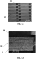
- FIG. 1a The stainless steel fiber fabric 100 according to embodiments of the invention is shown schematically in FIG. 1a , wherein the stainless steel yarn 10 comprising multiple untwisted steel fibers 1 is held straight by the untwisted polyester yarn 20.
- FIG. 1b illustrates microscopy images of cross-sectional views of some layers of stainless steel fiber fabric 100.
- FIG. 1c illustrates a plan view of the stainless steel fiber fabric 100 according to embodiments of the invention, a piece of which is zoomed in is illustrated in FIG. 1d . Tables 1 and 2 below provide more information about the steel fiber and steel fiber structure / fabric.
- Table 1 illustrates the characteristics of the steel fiber fabric used in accordance with embodiments of the invention: warp Untwisted PET thread/yarn weft 275 fibers, 1520 tex Tissue structure Plain weave Surface density [g/m2] 1425 Distance of warp [yarn/cm] 1.25 Distance of weft [yarn/cm] 9.35 Warp yarn thickness [mm] 0.08 width [mm] 1.75 Weft yarn thickness [mm] 0.45 width [mm] 0.8
- Table 2 describes the mechanical properties of the stainless steel fibers (preferably having a diameter of 30 ⁇ m): Stainless steel fibers Young's modulus, E ⁇ 193 GPa Strength, ⁇ UTS 660 ⁇ 4 MPa Elongation at break, ⁇ ULT ⁇ 20 % Yield strength (0,2%), ⁇ yield ⁇ 365 MPa
- the carbon fiber fabric used in embodiments of the invention is a Hexcel fabric: a 2/2 twill fabric consisting of 3K yarns with AS2CJ carbon fibers having a surface weight of 160 g/m 2 .
- the matrix material is an epoxy resin, more specifically an Araldite LY-1564-SP and the hardener is Aradur 3486-BD.
- the hybrid composite according to embodiments of the invention is a hybrid composite plate material comprising various layers of alternating carbon fiber layer (comprising a carbon fiber fabric) and a stainless steel fiber layer (comprising a steel fabric).
- the steel fiber layer is preferably positioned on the outside each time. This because the greatest distortions occur on the outside in bending and impact, and these large deformations can then be captured by the steel.
- laminates are provided with only one or two layers of ductile fibers because of the heavy surface weight. But this is only a specific embodiment and other configurations can also be provided (for example, by spreading different thin ductile fibrous layers between the brittle fibrous layers).
- Table 3 below shows the different plate laminates and configurations tested.
- A2, A3 hybrid laminate In the case of an asymmetric (A2, A3) hybrid laminate according to embodiments of the invention, one layer of steel fibers was placed on the underside.
- S2, S3 In the case of the symmetrical laminates (S2, S3), both a steel fiber layer was provided at the top and a steel fiber layer on the underside.
- the reference plate does not comprise a steel fiber layer for hybridization and thus concerns a single carbon composite.
- Table 3 Properties of the produced hybrid laminates according to the present invention and the reference carbon laminate.
- the plates listed in Table 3 can be produced by vacuum infusion.
- the dry (carbon and stainless steel) fibers are positioned on a flat plate and infused with a matrix material, for example epoxy resin, under vacuum to form a hybrid composite.
- embodiments of the invention also provide other shapes or profiles, such as, for example, I, C or H profiles or tubes comprising a curvature.
- Different types of tubes are also possible, such as tubes comprising different cross-sections (e.g., circular, square, polygon, etc.). It is an advantage of embodiments of the present invention that helps curvature to improve the structural mechanical characteristics (impact and residual strength) of the hybrid composite. Table 4 below summarizes the characteristics of the produced hybrid tubes according to the present invention and the reference tube.
- Type Abbreviation % thickness of steel fiber layer relative to total thickness Weight increase % Volume % of steel fibers Total thickness plate (mm) Reference plate REF 0 0 0 2 Steel fiber layer at the outside O1,2 27 12 10,8 1,7 O1,25HM 26 13 10,4 1,75 O1,4 24 23 9,6 1,9 O1,6 22 34 8,8 2,1 Steel fiber layer at the inside I1,4 24 23 9,6 1,9 I1,6 22 34 8,8 2,1
- Table 4 illustrates the characteristics of hybrid tubes of circular cross-section according to embodiments of the invention and a reference carbon tube (which does not include stainless steel fiber).
- the tubes can also be produced using the above-mentioned vacuum infusion.
- a single layer of steel fibers is used, preferably on the outer surface of the tube, and the thickness is adjusted with respect to the number of layers of carbon fibers so that the outer diameter remains constant (32 mm) and the wall thickness (and weight) varies between the different tubes.
- the abbreviation "O” refers to a tube where the steel fibers are on the outside of the tube, for example an existing carbon composite tube, while the "I” refers to steel fibers being laminated on the inside of the tube.
- Embodiments of the present invention provide materials of low specific weight and high stiffness. Using the classical laminate theory and measured characteristics of steel fiber composites, the stiffness and weight of the hybrid composites according to embodiments of the invention can be calculated accurately.
- the thickness and layer structure of the hybrid laminates is chosen so that the geometric tensile stiffness is similar or higher than the reference carbon fiber laminate.
- the thickness of the laminate may be smaller (with a beneficial effect on weight) without affecting the deformation at a particular load.
- the thickness of the laminate in the case of A3 and S3 is similar or slightly higher, for even higher stiffness but with a higher weight gain.
- the thickness of the plate was chosen so that a certain force (in N) would yield a similar deformation (identical geometric stiffness). In this way, the effect on the weight can be compared directly.
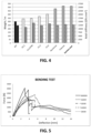
- Figure 2 illustrates the increase in weight for plates with a similar geometric tensile stiffness.
- a component designed with the hybrid structures (A2, A3 and S2) will show a limited weight gain (1-17%) relative to the reference material, but will still have a lower weight than the traditional metals.
- Single hybrid laminate S3 has a higher weight gain (32%) compared to the metals (26-31%), but was overly dimentioned (the geometric stiffness is 25% higher than the reference and the metals) (see Table 5).
- Table 5 provides an overview of the weight gain, material and geometric stiffness of the reference carbon laminate, the produced hybrid laminates and traditional metals.
- Thickness t (mm) Weight % increase (W%)
- Gpa Geometric stiffness (Gpa mm 2 ) REF 4 0 6234 50,5 202 S2 3,7 17 7309 57,5 213 S3 4,4 32 8255 56,7 250 A2 3,7 1 6268 53,5 198 A3 4,3 17 7282 53,2 229 Aluminium 2,9 26 7830 70,0 203 Titanium 1,85 31 8196 110,0 201 Stainless steel (RVS) 1,05 31 8190 195,0 205
- laminate A2 Due to the high stiffness of the steel fibers on the outside, laminate A2 has almost the same geometric bending stiffness (-9%), without an increase in weight (+ 1%) relative to the reference carbon fiber material.
- Table 6 provides an overview of the weight gain, material and geometric stiffness of the reference carbon laminate, the produced hybrid laminates according to embodiments of the invention and conventional single metals.
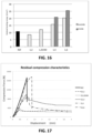
- the power displacement diagram for the hybrids shows a nonlinear gradient from about 2 mm deflection, which means that there is some kind of warning that the maximum strength is almost reached, in the form of permanent deformation. After reaching the maximum strength, the force drops, but more gradually than in the case of the reference carbon fiber laminate.
- Figure 6 shows that the absolute strength of the hybrid laminates is slightly lower than the reference carbon fiber laminate, but the energy dissipated during the deformation / breaking of the laminate is 35 - 125% higher. This energy dissipation is calculated as the area under the force displacement curve. It is important to mention that the values were not normalized according to the thickness of the material. This is because the plate thickness is adjusted to achieve the same geometric stiffness and thus with a higher material stiffness of the laminate a lower sheet thickness can be used (to reduce the absolute weight). This ensures that there is inherently less material (with laminates A2 and S2), with a logical consequence that the maximum strength is lower. However, this decrease in strength is compensated by the better fracture behaviour and the higher energy dissipation during fracture. In traditional composites, a design often becomes too strongly dimensioned because of the dramatic fracture behavior. The decrease in strength of the hybrid laminates will therefore not necessarily require another design, because of the strong improvements in fracture and energy dissipation.
- tubes were impacted with an energy of 50J.
- tubes with an outside diameter of 32 mm were laid on two support points 300 mm apart.
- the impact was realized with a 20 mm diameter finger indentor.
- the impact setup is therefore a 3-point bending test, with both sides laid free with a 300 mm span.
- hybrid laminates according to embodiments of the present invention having a width of 20mm were clamped into a Huntsman impactor.
- the impact was realized with a finger indentor having a diameter of 20mm and the clamping was performed using a ring having an inner diameter of 40 mm.
- the impact setup is therefore a bending test with both sides of the material being clamped with a 40 mm span.
- the laminates were impacted with an energy of 4J, 8J, 16J and 32J and thereafter the residual mechanical properties were tested by means of a tensile test and a bending test.
- Figure 11 illustrates the retention of the residual tensile force in function of the impact energy on the sample for the tensile test. Again, the effect of the reduced thickness is strongly visible.
- the laminates S2 and A2 exhibit a lower maximum force in an unimpacted test sample (0J).
- the residual strength at low impact energies is lower than the reference material. This is caused, on the one hand, by impacting a thinner laminate, but on the other hand also because in the tensile test the diameter of the material is thinner because of the reduced thickness. Nevertheless, the decrease in tensile strength due to the impact is more gradual compared with the reference material.
- Figure 12 illustrates, in function of the impact energy on the tensile test sample, how much energy can still be dissipated in a tensile test on an impacted sample.
- the effect of the reduced thickness is important. Again, the decrease is more gradual for the hybrid laminates. For an impact of 16J and higher, all hybrid laminates score better and these laminates can still dissipate 1/3 of energy relative to the reference laminate.
- a similar test was performed with a 3-point bending test as 2nd test. It is important that the load is applied in the same way : impact is measured in 3-point bending and residual properties are measured in 3-point bending. Because this is a similar load, the cracks that occur upon impact grow more easily.
- the power that still can be handled by the reference laminate decreases faster compared to the previous test.
- the laminate in the tensile direction has a residual strength. In bending, the maximum force is negligibly small.
- the energy that can still be dissipated in a bending test is 126% - 465% higher in the steel fiber hybrids.
- Figure 15 illustrates the residual bending strength of the tubes after an impact of 30J.
- the wall thickness of the tubes is so lower than the reference tube that the residual strength is lower than the reference. This is again because there is less material to absorb the impact energy. If the wall thickness is only slightly lower ("1.4") or the same ("1.6") then the residual strength is a lot higher. With the tube 01.6, the residual bending strength after an impact of 30J to 113% is higher.
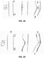
- Figure 17 shows the power displacement chart of tubes subjected to a compression test after 30J impact (with the same set-up).
- the material In case of impact on a carbon fiber laminate or tube, the material will is resilient. The internal damage present is difficult or not visible.
- An advantage of using the hybrid laminates according to embodiments of the invention is that possible damage (before complete breakage occurs) in the composite component is much easier to trace.
- internal damage can only be traced through complex inspection techniques (eg CT scan, ultrasound).
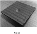
- An impact load on a hybrid composite with steel fibers will not only cause internal damage but also leave a dirt in the composite component (as illustrated in Figure 20 ), which is easy to inspect.
- the size of the denture may be investigated to estimate the amount of internal damage in the underlying carbon fiber composite. In order to measure the damage effectively, only locally expensive measuring equipment must be used.
- a preferred parameter is the local fiber volume fraction. With a high gasket, steel fibers may have a higher fracture elongation. It is therefore preferable, after the production of the fibers, to insert the fibers into the composite as much as possible in the same packing.
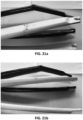
- Hybrid composites according to embodiments of the present invention can be used, for example in tubular form, as a front fork of a bicycle. This is illustrated in Figures 21a and 21b .
- White is the hybrid variant according to the present invention, black is the full carbon fiber variant.
- the picture shows the improved effect of the hybrid composites in the tested front forks.
- the front forks were unilaterally supported on the steering tube and were impacted three times with 110 J. Again, it is important that the test set-up plays an important role in the energy that can be dissipated. Because the full front fork can elastically spring, much of the energy is transformed into elastic deformation. Therefore, the energy needed to cause such damage is that large.
Landscapes
- Chemical & Material Sciences (AREA)
- Engineering & Computer Science (AREA)
- Mechanical Engineering (AREA)
- Textile Engineering (AREA)
- Organic Chemistry (AREA)
- Manufacturing & Machinery (AREA)
- Materials Engineering (AREA)
- Health & Medical Sciences (AREA)
- Chemical Kinetics & Catalysis (AREA)
- Medicinal Chemistry (AREA)
- Polymers & Plastics (AREA)
- Composite Materials (AREA)
- Inorganic Chemistry (AREA)
- Laminated Bodies (AREA)
- Woven Fabrics (AREA)
- Developing Agents For Electrophotography (AREA)
- Polymers With Sulfur, Phosphorus Or Metals In The Main Chain (AREA)
Claims (12)
- Ein Hybridverbundstoff, wobei der Hybridverbundstoff umfasst: eine thermoplastische oder duroplastische Matrix, in der spröde und duktile Fasern (1) vorhanden sind, die bei Raumtemperatur und Standardatmosphärendruck jeweils spröde und duktile Eigenschaften aufweisen, dadurch gekennzeichnet, dass die duktilen Fasern einzeln vorhanden sind oder in einem Garn enthalten sind, das einen Verdrehwinkel von weniger als 5° aufweist oder unverdreht ist, das Youngscher Modul der spröden und duktilen Fasern größer als 150 GPa ist, die duktilen Fasern eine Bruchdehnung in Prozenten, in denen sich ein Material in Bezug auf die ursprüngliche Länge erstreckt, mit einer Bruchlast aufweist, die bei Raumtemperatur und Standardatmosphärendruck größer als 5% ist, wobei die Fasern konfiguriert sind, sodass die duktilen Fasern (1) des Hybridverbundstoffs bei Stoß oder Überlastung Energie durch plastische Verformung der duktilen Fasern (1) ableiten, und der Hybridverbundstoff Integrität nach Stoß oder Überlastung behält, wobei die spröden Fasern Carbonfasern sind und die duktilen Fasern Stahlfasern sind.
- Der Hybridverbundstoff nach dem vorstehenden Anspruch, wobei die Faservolumenfraktion der duktilen Fasern (1) geringer als 50% der Gesamtmenge an Fasern, vorzugsweise geringer als 20% ist, beispielsweise zwischen 3% und 10% liegt.
- Hybridverbundstoff nach einem der vorstehenden Ansprüche, wobei die Fasern vorzugsweise einen Durchmesser von weniger als 100 µm und vorzugsweise weniger als 40 µm aufweisen.
- Der Hybridverbundstoff nach einem der vorstehenden Ansprüche, wobei die spröden und/oder duktilen Fasern in einer Richtung in einer homogenen Schicht platziert sind.
- Der Hybridverbundstoff nach einem der vorstehenden Ansprüche, wobei die duktilen Fasern in einem Stoff (100) bereitgestellt sind.
- Der Hybridverbundstoff nach einem der vorstehenden Ansprüche, wobei die duktilen Fasern mit ihrer Längsachse senkrecht zu einer erwarteten Rissbildungsrichtung des Verbundstoffs bereitgestellt sind.
- Der Hybridverbundstoff nach einem der vorstehenden Ansprüche, wobei die spröden Fasern und duktilen Fasern in einer Zwischenschichtkonfiguration bereitgestellt sind, die zu einem Hybridlaminat mit mindestens einer duktilen Faserschicht führt.
- Der Hybridverbundstoff nach Anspruch 7, wobei die mindestens eine duktile faserige Schicht auf mindestens einer Oberfläche des Verbundstoffs positioniert ist, wo die größten Verzerrungen auftreten können, und wo die Rissbildung die größte Öffnung aufzeigen kann, und/oder
wobei die mindestens eine duktile faserige Schicht auf mindestens einer größten Oberfläche von Verbundstoff positioniert ist, wo die größten Verzerrungen auftreten können, und wo die Rissbildung die größte Öffnung aufzeigen kann. - Der Hybridverbundstoff nach einem der vorstehenden Ansprüche, wobei die duktilen Fasern nichtrostende Stahlfasern sind.
- Eine Fahrzeugkomponente, die einen Hybridverbundstoff nach einem der Ansprüche 1 bis 9 umfasst.
- Ein Verfahren zum Herstellen eines Hybridverbundstoffs nach einem der Ansprüche 1 bis 9, wobei das Verfahren umfasst- Platzieren der spröden und duktilen Fasern in einer Form mit einer vorbestimmten Gestalt;- Infundieren der Fasern mit einem thermoplastischen oder duroplastischen Harz, um einen Hybridverbundstoff zu bilden.
- Ein Verfahren zum Herstellen eines Hybridverbundstoffs nach einem der Ansprüche 1 bis 9, wobei das Verfahren umfasst:- Bereitstellen eines Gegenstandes, der spröde Fasern enthält,- Bereitstellen mindestens einer duktilen Faserschicht auf mindestens einer Oberfläche des Artikels.
Applications Claiming Priority (2)
| Application Number | Priority Date | Filing Date | Title |
|---|---|---|---|
| BE2016/5696A BE1024565B1 (nl) | 2016-09-15 | 2016-09-15 | Hybride composiet |
| PCT/EP2017/073375 WO2018050875A1 (en) | 2016-09-15 | 2017-09-15 | Hybrid composite |
Publications (3)
| Publication Number | Publication Date |
|---|---|
| EP3512697A1 EP3512697A1 (de) | 2019-07-24 |
| EP3512697C0 EP3512697C0 (de) | 2024-11-27 |
| EP3512697B1 true EP3512697B1 (de) | 2024-11-27 |
Family
ID=56990192
Family Applications (1)
| Application Number | Title | Priority Date | Filing Date |
|---|---|---|---|
| EP17768449.5A Active EP3512697B1 (de) | 2016-09-15 | 2017-09-15 | Hybridkomposit |
Country Status (7)
| Country | Link |
|---|---|
| US (1) | US11326029B2 (de) |
| EP (1) | EP3512697B1 (de) |
| CN (1) | CN109952194B (de) |
| BE (1) | BE1024565B1 (de) |
| CA (1) | CA3036601A1 (de) |
| TW (1) | TWI767938B (de) |
| WO (1) | WO2018050875A1 (de) |
Families Citing this family (8)
| Publication number | Priority date | Publication date | Assignee | Title |
|---|---|---|---|---|
| WO2020172379A1 (en) * | 2019-02-21 | 2020-08-27 | Shanghai Yanfeng Jinqiao Automotive Trim Systems Co. Ltd. | Vehicle interior component |
| BE1028283B1 (nl) | 2020-05-08 | 2021-12-06 | Rein4Ced | Fietsframe en werkwijze voor de vervaardiging |
| JP1695231S (de) * | 2020-09-11 | 2021-09-21 | ||
| USD967735S1 (en) * | 2021-02-23 | 2022-10-25 | Foshan Jidong Vehicle Industry Co., Ltd. | Electric bicycle |
| FR3121624B1 (fr) * | 2021-04-07 | 2023-11-17 | Safran Aircraft Engines | Ajustement du torsadage pour optimiser les moules et la mise en forme des architectures textiles |
| CN117320586A (zh) * | 2021-06-18 | 2023-12-29 | 米沃奇电动工具公司 | 具有抗冲击性能材料的安全帽 |
| USD965477S1 (en) * | 2021-08-11 | 2022-10-04 | Fuhai ZHANG | Electric bicycle |
| USD957291S1 (en) * | 2021-11-02 | 2022-07-12 | Guangzhou BionC Intelligent Sport Equipment Co., Ltd | Electric bicycle |
Family Cites Families (12)
| Publication number | Priority date | Publication date | Assignee | Title |
|---|---|---|---|---|
| US5344689A (en) * | 1991-08-09 | 1994-09-06 | Kabushiki Kaisha Kobe Seiko Sho | Carbon fiber prepreg and carbon fiber reinforced resin composite |
| JP2619822B2 (ja) * | 1995-02-28 | 1997-06-11 | 本田技研工業株式会社 | ステアリングステムコンポーネント |
| US5762352A (en) * | 1996-03-15 | 1998-06-09 | Lee; Kyu-Wang | Bicycle fork having a fiber reinforced steerer tube and fiber reinforced crown and blades and method of making same |
| BR0215897B1 (pt) * | 2002-10-23 | 2013-07-16 | prepreg e método para sua produção | |
| US20070068605A1 (en) * | 2005-09-23 | 2007-03-29 | U.I.T., Llc | Method of metal performance improvement and protection against degradation and suppression thereof by ultrasonic impact |
| ATE523419T1 (de) * | 2006-02-14 | 2011-09-15 | Campagnolo Srl | Fahrradtretkurbel und herstellungsmethode für eine derartige tretkurbel |
| US20140335752A1 (en) * | 2006-05-22 | 2014-11-13 | Innegra Technologies, Llc | Hybrid Composite Structure |
| FR2911317A3 (fr) * | 2007-01-15 | 2008-07-18 | Ma Pei Chuan | Tube de cadre de bicyclette |
| US20090075076A1 (en) | 2007-09-13 | 2009-03-19 | The Regents Of The University Of Michigan | Impact resistant strain hardening brittle matrix composite for protective structures |
| PL2702092T3 (pl) * | 2011-04-26 | 2018-03-30 | Bekaert Sa Nv | Kompozyty wzmacniane włóknem stalowym |
| CN103569283B (zh) * | 2012-08-08 | 2016-12-07 | 合肥杰事杰新材料股份有限公司 | 一种自毁式塑料吸能结构及其用途 |
| CN104097727B (zh) * | 2013-04-09 | 2017-09-05 | 合肥杰事杰新材料股份有限公司 | 一种注塑式塑料自行车 |
-
2016
- 2016-09-15 BE BE2016/5696A patent/BE1024565B1/nl active IP Right Grant
-
2017
- 2017-09-15 US US16/333,319 patent/US11326029B2/en active Active
- 2017-09-15 TW TW106131862A patent/TWI767938B/zh active
- 2017-09-15 WO PCT/EP2017/073375 patent/WO2018050875A1/en not_active Ceased
- 2017-09-15 CN CN201780056659.0A patent/CN109952194B/zh active Active
- 2017-09-15 EP EP17768449.5A patent/EP3512697B1/de active Active
- 2017-09-15 CA CA3036601A patent/CA3036601A1/en active Pending
Also Published As
| Publication number | Publication date |
|---|---|
| TWI767938B (zh) | 2022-06-21 |
| US20190248969A1 (en) | 2019-08-15 |
| CA3036601A1 (en) | 2018-03-22 |
| US11326029B2 (en) | 2022-05-10 |
| BE1024565A1 (nl) | 2018-04-10 |
| EP3512697C0 (de) | 2024-11-27 |
| EP3512697A1 (de) | 2019-07-24 |
| TW201827208A (zh) | 2018-08-01 |
| BE1024565B1 (nl) | 2018-04-17 |
| WO2018050875A1 (en) | 2018-03-22 |
| CN109952194A (zh) | 2019-06-28 |
| CN109952194B (zh) | 2021-11-02 |
Similar Documents
| Publication | Publication Date | Title |
|---|---|---|
| EP3512697B1 (de) | Hybridkomposit | |
| Elanchezhian et al. | Mechanical behaviour of glass and carbon fibre reinforced composites at varying strain rates and temperatures | |
| Rajkumar et al. | Investigation of tensile and bending behavior of aluminum based hybrid fiber metal laminates | |
| Aktaş et al. | Impact and post impact behavior of layer fabric composites | |
| EP2864109B1 (de) | Hybrider selbstverstärkter verbundstoff | |
| EP1584451A1 (de) | Gewebe, Fadenbündel aus Kontinufilamenten und Fadenstränge zum Formen von Verstärkungsschichten für Verbundwerkstoffelemente mit einer Harzmatrix | |
| Kuan et al. | The fracture properties of environmental-friendly fiber metal laminates | |
| Stelzer et al. | Fatigue behaviour of composite–composite joints reinforced with cold metal transfer welded pins | |
| JP2018039115A (ja) | 繊維強化樹脂複合構造体及び高圧容器、並びにこれらの製造方法 | |
| JP2013525149A (ja) | 炭素繊維強化プラスチック引抜成形バー | |
| Khan et al. | Resistance of glass-fibre reinforced polymer composites to increasing compressive strain rates and loading rates | |
| Ekşi et al. | Three point bending behavior of woven glass, aramid and carbon fiber reinforced hybrid composite tube | |
| Gautam et al. | Necking behaviour of flattened tubular braided composites | |
| Sun et al. | Mechanical behaviors of 2D and 3D basalt fiber woven composites under various strain rates | |
| Khalili et al. | Mechanical behavior of notched plate repaired with polymer composite and smart patches-experimental study | |
| Toha et al. | Preliminary development of laminated nanocomposite from nanocellulose-Kevlar for military application | |
| Miandowab et al. | Influences of freeze, water immersion, and cyclic freeze-thaw environmental conditions on crashworthiness performance of GFRP circular tubes subjected to axial and lateral quasi-static load | |
| JP2024521341A (ja) | 圧縮成形防弾物品 | |
| Mohammed et al. | Ballistic impact velocity response of carbon fibre reinforced aluminium alloy laminates for aero-engine | |
| Hussain et al. | Fabrication of epoxy composites reinforced with bamboo fibers | |
| Hartley et al. | Column interaction in tufted sandwich structures under edgewise loading | |
| Roberts et al. | Effect of strain rate on the tensile failure of glass-fibre braided tubes | |
| Yoshimura et al. | Improvement of out-of-plane impact damage resistance of CFRP due to through-the-thickness stitching | |
| Eiamnipon et al. | Low velocity impact responses and impact-induced damages on steel cord-rubber composite | |
| Palanikumar et al. | 2 Influence of fibre arrangement on mechanical properties of glass fibre-reinforced aluminium sandwich laminates |
Legal Events
| Date | Code | Title | Description |
|---|---|---|---|
| STAA | Information on the status of an ep patent application or granted ep patent |
Free format text: STATUS: UNKNOWN |
|
| STAA | Information on the status of an ep patent application or granted ep patent |
Free format text: STATUS: THE INTERNATIONAL PUBLICATION HAS BEEN MADE |
|
| PUAI | Public reference made under article 153(3) epc to a published international application that has entered the european phase |
Free format text: ORIGINAL CODE: 0009012 |
|
| STAA | Information on the status of an ep patent application or granted ep patent |
Free format text: STATUS: REQUEST FOR EXAMINATION WAS MADE |
|
| 17P | Request for examination filed |
Effective date: 20190409 |
|
| AK | Designated contracting states |
Kind code of ref document: A1 Designated state(s): AL AT BE BG CH CY CZ DE DK EE ES FI FR GB GR HR HU IE IS IT LI LT LU LV MC MK MT NL NO PL PT RO RS SE SI SK SM TR |
|
| AX | Request for extension of the european patent |
Extension state: BA ME |
|
| DAV | Request for validation of the european patent (deleted) | ||
| DAX | Request for extension of the european patent (deleted) | ||
| STAA | Information on the status of an ep patent application or granted ep patent |
Free format text: STATUS: EXAMINATION IS IN PROGRESS |
|
| 17Q | First examination report despatched |
Effective date: 20200826 |
|
| GRAP | Despatch of communication of intention to grant a patent |
Free format text: ORIGINAL CODE: EPIDOSNIGR1 |
|
| STAA | Information on the status of an ep patent application or granted ep patent |
Free format text: STATUS: GRANT OF PATENT IS INTENDED |
|
| INTG | Intention to grant announced |
Effective date: 20240619 |
|
| GRAS | Grant fee paid |
Free format text: ORIGINAL CODE: EPIDOSNIGR3 |
|
| GRAA | (expected) grant |
Free format text: ORIGINAL CODE: 0009210 |
|
| STAA | Information on the status of an ep patent application or granted ep patent |
Free format text: STATUS: THE PATENT HAS BEEN GRANTED |
|
| AK | Designated contracting states |
Kind code of ref document: B1 Designated state(s): AL AT BE BG CH CY CZ DE DK EE ES FI FR GB GR HR HU IE IS IT LI LT LU LV MC MK MT NL NO PL PT RO RS SE SI SK SM TR |
|
| REG | Reference to a national code |
Ref country code: GB Ref legal event code: FG4D |
|
| RIN1 | Information on inventor provided before grant (corrected) |
Inventor name: DE GREEF, NIELS Inventor name: CALLENS, MICHAEL G. |
|
| REG | Reference to a national code |
Ref country code: CH Ref legal event code: EP |
|
| REG | Reference to a national code |
Ref country code: DE Ref legal event code: R096 Ref document number: 602017086385 Country of ref document: DE |
|
| REG | Reference to a national code |
Ref country code: IE Ref legal event code: FG4D |
|
| U01 | Request for unitary effect filed |
Effective date: 20241217 |
|
| U07 | Unitary effect registered |
Designated state(s): AT BE BG DE DK EE FI FR IT LT LU LV MT NL PT RO SE SI Effective date: 20250110 |
|
| PG25 | Lapsed in a contracting state [announced via postgrant information from national office to epo] |
Ref country code: HR Free format text: LAPSE BECAUSE OF FAILURE TO SUBMIT A TRANSLATION OF THE DESCRIPTION OR TO PAY THE FEE WITHIN THE PRESCRIBED TIME-LIMIT Effective date: 20241127 Ref country code: IS Free format text: LAPSE BECAUSE OF FAILURE TO SUBMIT A TRANSLATION OF THE DESCRIPTION OR TO PAY THE FEE WITHIN THE PRESCRIBED TIME-LIMIT Effective date: 20250327 |
|
| PG25 | Lapsed in a contracting state [announced via postgrant information from national office to epo] |
Ref country code: ES Free format text: LAPSE BECAUSE OF FAILURE TO SUBMIT A TRANSLATION OF THE DESCRIPTION OR TO PAY THE FEE WITHIN THE PRESCRIBED TIME-LIMIT Effective date: 20241127 |
|
| PG25 | Lapsed in a contracting state [announced via postgrant information from national office to epo] |
Ref country code: NO Free format text: LAPSE BECAUSE OF FAILURE TO SUBMIT A TRANSLATION OF THE DESCRIPTION OR TO PAY THE FEE WITHIN THE PRESCRIBED TIME-LIMIT Effective date: 20250227 |
|
| PG25 | Lapsed in a contracting state [announced via postgrant information from national office to epo] |
Ref country code: GR Free format text: LAPSE BECAUSE OF FAILURE TO SUBMIT A TRANSLATION OF THE DESCRIPTION OR TO PAY THE FEE WITHIN THE PRESCRIBED TIME-LIMIT Effective date: 20250228 |
|
| PG25 | Lapsed in a contracting state [announced via postgrant information from national office to epo] |
Ref country code: PL Free format text: LAPSE BECAUSE OF FAILURE TO SUBMIT A TRANSLATION OF THE DESCRIPTION OR TO PAY THE FEE WITHIN THE PRESCRIBED TIME-LIMIT Effective date: 20241127 |
|
| PG25 | Lapsed in a contracting state [announced via postgrant information from national office to epo] |
Ref country code: RS Free format text: LAPSE BECAUSE OF FAILURE TO SUBMIT A TRANSLATION OF THE DESCRIPTION OR TO PAY THE FEE WITHIN THE PRESCRIBED TIME-LIMIT Effective date: 20250227 |
|
| PG25 | Lapsed in a contracting state [announced via postgrant information from national office to epo] |
Ref country code: SM Free format text: LAPSE BECAUSE OF FAILURE TO SUBMIT A TRANSLATION OF THE DESCRIPTION OR TO PAY THE FEE WITHIN THE PRESCRIBED TIME-LIMIT Effective date: 20241127 |
|
| PG25 | Lapsed in a contracting state [announced via postgrant information from national office to epo] |
Ref country code: SK Free format text: LAPSE BECAUSE OF FAILURE TO SUBMIT A TRANSLATION OF THE DESCRIPTION OR TO PAY THE FEE WITHIN THE PRESCRIBED TIME-LIMIT Effective date: 20241127 |
|
| PG25 | Lapsed in a contracting state [announced via postgrant information from national office to epo] |
Ref country code: CZ Free format text: LAPSE BECAUSE OF FAILURE TO SUBMIT A TRANSLATION OF THE DESCRIPTION OR TO PAY THE FEE WITHIN THE PRESCRIBED TIME-LIMIT Effective date: 20241127 |
|
| PLBE | No opposition filed within time limit |
Free format text: ORIGINAL CODE: 0009261 |
|
| STAA | Information on the status of an ep patent application or granted ep patent |
Free format text: STATUS: NO OPPOSITION FILED WITHIN TIME LIMIT |
|
| U20 | Renewal fee for the european patent with unitary effect paid |
Year of fee payment: 9 Effective date: 20250924 |
|
| 26N | No opposition filed |
Effective date: 20250828 |