EP3512463B1 - Passive middle ear prosthesis - Google Patents
Passive middle ear prosthesis Download PDFInfo
- Publication number
- EP3512463B1 EP3512463B1 EP17851383.4A EP17851383A EP3512463B1 EP 3512463 B1 EP3512463 B1 EP 3512463B1 EP 17851383 A EP17851383 A EP 17851383A EP 3512463 B1 EP3512463 B1 EP 3512463B1
- Authority
- EP
- European Patent Office
- Prior art keywords
- engagement
- engagement legs
- stapes
- prosthesis
- legs
- Prior art date
- Legal status (The legal status is an assumption and is not a legal conclusion. Google has not performed a legal analysis and makes no representation as to the accuracy of the status listed.)
- Active
Links
- 210000000959 ear middle Anatomy 0.000 title claims description 34
- 210000001050 stape Anatomy 0.000 claims description 46
- 210000003454 tympanic membrane Anatomy 0.000 claims description 21
- 239000000463 material Substances 0.000 claims description 11
- 238000000034 method Methods 0.000 claims description 7
- 238000005452 bending Methods 0.000 claims description 5
- 230000008447 perception Effects 0.000 claims description 4
- 238000003698 laser cutting Methods 0.000 claims description 3
- 239000007769 metal material Substances 0.000 claims description 3
- 210000002414 leg Anatomy 0.000 description 50
- 210000003477 cochlea Anatomy 0.000 description 7
- 239000012528 membrane Substances 0.000 description 7
- 210000001785 incus Anatomy 0.000 description 4
- 210000001699 lower leg Anatomy 0.000 description 4
- 241000878128 Malleus Species 0.000 description 3
- 239000007943 implant Substances 0.000 description 3
- 210000002331 malleus Anatomy 0.000 description 3
- 230000007246 mechanism Effects 0.000 description 3
- 210000003484 anatomy Anatomy 0.000 description 2
- 210000000860 cochlear nerve Anatomy 0.000 description 2
- 210000000883 ear external Anatomy 0.000 description 2
- 239000012530 fluid Substances 0.000 description 2
- 230000001771 impaired effect Effects 0.000 description 2
- 238000002513 implantation Methods 0.000 description 2
- 208000000781 Conductive Hearing Loss Diseases 0.000 description 1
- 206010010280 Conductive deafness Diseases 0.000 description 1
- 206010046996 Varicose vein Diseases 0.000 description 1
- 208000027418 Wounds and injury Diseases 0.000 description 1
- 230000036982 action potential Effects 0.000 description 1
- 230000006978 adaptation Effects 0.000 description 1
- 230000003321 amplification Effects 0.000 description 1
- 230000005540 biological transmission Effects 0.000 description 1
- 210000001124 body fluid Anatomy 0.000 description 1
- 239000010839 body fluid Substances 0.000 description 1
- 210000004556 brain Anatomy 0.000 description 1
- 210000000262 cochlear duct Anatomy 0.000 description 1
- 208000023563 conductive hearing loss disease Diseases 0.000 description 1
- 230000006735 deficit Effects 0.000 description 1
- 238000005530 etching Methods 0.000 description 1
- 230000006870 function Effects 0.000 description 1
- 210000003128 head Anatomy 0.000 description 1
- 208000014674 injury Diseases 0.000 description 1
- 238000003780 insertion Methods 0.000 description 1
- 230000037431 insertion Effects 0.000 description 1
- 239000002184 metal Substances 0.000 description 1
- 230000004048 modification Effects 0.000 description 1
- 238000012986 modification Methods 0.000 description 1
- 230000001537 neural effect Effects 0.000 description 1
- 238000003199 nucleic acid amplification method Methods 0.000 description 1
- 230000008569 process Effects 0.000 description 1
- 230000004044 response Effects 0.000 description 1
- 210000001079 scala tympani Anatomy 0.000 description 1
- 210000001605 scala vestibuli Anatomy 0.000 description 1
- 210000001323 spiral ganglion Anatomy 0.000 description 1
- 230000000638 stimulation Effects 0.000 description 1
- 239000000758 substrate Substances 0.000 description 1
- 230000008733 trauma Effects 0.000 description 1
- 208000027185 varicose disease Diseases 0.000 description 1
Images


Classifications
-
- A—HUMAN NECESSITIES
- A61—MEDICAL OR VETERINARY SCIENCE; HYGIENE
- A61F—FILTERS IMPLANTABLE INTO BLOOD VESSELS; PROSTHESES; DEVICES PROVIDING PATENCY TO, OR PREVENTING COLLAPSING OF, TUBULAR STRUCTURES OF THE BODY, e.g. STENTS; ORTHOPAEDIC, NURSING OR CONTRACEPTIVE DEVICES; FOMENTATION; TREATMENT OR PROTECTION OF EYES OR EARS; BANDAGES, DRESSINGS OR ABSORBENT PADS; FIRST-AID KITS
- A61F2/00—Filters implantable into blood vessels; Prostheses, i.e. artificial substitutes or replacements for parts of the body; Appliances for connecting them with the body; Devices providing patency to, or preventing collapsing of, tubular structures of the body, e.g. stents
- A61F2/02—Prostheses implantable into the body
- A61F2/18—Internal ear or nose parts, e.g. ear-drums
-
- A—HUMAN NECESSITIES
- A61—MEDICAL OR VETERINARY SCIENCE; HYGIENE
- A61L—METHODS OR APPARATUS FOR STERILISING MATERIALS OR OBJECTS IN GENERAL; DISINFECTION, STERILISATION OR DEODORISATION OF AIR; CHEMICAL ASPECTS OF BANDAGES, DRESSINGS, ABSORBENT PADS OR SURGICAL ARTICLES; MATERIALS FOR BANDAGES, DRESSINGS, ABSORBENT PADS OR SURGICAL ARTICLES
- A61L27/00—Materials for grafts or prostheses or for coating grafts or prostheses
- A61L27/02—Inorganic materials
- A61L27/04—Metals or alloys
-
- A—HUMAN NECESSITIES
- A61—MEDICAL OR VETERINARY SCIENCE; HYGIENE
- A61F—FILTERS IMPLANTABLE INTO BLOOD VESSELS; PROSTHESES; DEVICES PROVIDING PATENCY TO, OR PREVENTING COLLAPSING OF, TUBULAR STRUCTURES OF THE BODY, e.g. STENTS; ORTHOPAEDIC, NURSING OR CONTRACEPTIVE DEVICES; FOMENTATION; TREATMENT OR PROTECTION OF EYES OR EARS; BANDAGES, DRESSINGS OR ABSORBENT PADS; FIRST-AID KITS
- A61F2/00—Filters implantable into blood vessels; Prostheses, i.e. artificial substitutes or replacements for parts of the body; Appliances for connecting them with the body; Devices providing patency to, or preventing collapsing of, tubular structures of the body, e.g. stents
- A61F2/02—Prostheses implantable into the body
- A61F2/18—Internal ear or nose parts, e.g. ear-drums
- A61F2002/183—Ear parts
-
- A—HUMAN NECESSITIES
- A61—MEDICAL OR VETERINARY SCIENCE; HYGIENE
- A61F—FILTERS IMPLANTABLE INTO BLOOD VESSELS; PROSTHESES; DEVICES PROVIDING PATENCY TO, OR PREVENTING COLLAPSING OF, TUBULAR STRUCTURES OF THE BODY, e.g. STENTS; ORTHOPAEDIC, NURSING OR CONTRACEPTIVE DEVICES; FOMENTATION; TREATMENT OR PROTECTION OF EYES OR EARS; BANDAGES, DRESSINGS OR ABSORBENT PADS; FIRST-AID KITS
- A61F2220/00—Fixations or connections for prostheses classified in groups A61F2/00 - A61F2/26 or A61F2/82 or A61F9/00 or A61F11/00 or subgroups thereof
- A61F2220/0008—Fixation appliances for connecting prostheses to the body
-
- A—HUMAN NECESSITIES
- A61—MEDICAL OR VETERINARY SCIENCE; HYGIENE
- A61F—FILTERS IMPLANTABLE INTO BLOOD VESSELS; PROSTHESES; DEVICES PROVIDING PATENCY TO, OR PREVENTING COLLAPSING OF, TUBULAR STRUCTURES OF THE BODY, e.g. STENTS; ORTHOPAEDIC, NURSING OR CONTRACEPTIVE DEVICES; FOMENTATION; TREATMENT OR PROTECTION OF EYES OR EARS; BANDAGES, DRESSINGS OR ABSORBENT PADS; FIRST-AID KITS
- A61F2230/00—Geometry of prostheses classified in groups A61F2/00 - A61F2/26 or A61F2/82 or A61F9/00 or A61F11/00 or subgroups thereof
- A61F2230/0002—Two-dimensional shapes, e.g. cross-sections
- A61F2230/0004—Rounded shapes, e.g. with rounded corners
- A61F2230/0013—Horseshoe-shaped, e.g. crescent-shaped, C-shaped, U-shaped
-
- A—HUMAN NECESSITIES
- A61—MEDICAL OR VETERINARY SCIENCE; HYGIENE
- A61F—FILTERS IMPLANTABLE INTO BLOOD VESSELS; PROSTHESES; DEVICES PROVIDING PATENCY TO, OR PREVENTING COLLAPSING OF, TUBULAR STRUCTURES OF THE BODY, e.g. STENTS; ORTHOPAEDIC, NURSING OR CONTRACEPTIVE DEVICES; FOMENTATION; TREATMENT OR PROTECTION OF EYES OR EARS; BANDAGES, DRESSINGS OR ABSORBENT PADS; FIRST-AID KITS
- A61F2230/00—Geometry of prostheses classified in groups A61F2/00 - A61F2/26 or A61F2/82 or A61F9/00 or A61F11/00 or subgroups thereof
- A61F2230/0063—Three-dimensional shapes
- A61F2230/0095—Saddle-shaped
-
- A—HUMAN NECESSITIES
- A61—MEDICAL OR VETERINARY SCIENCE; HYGIENE
- A61F—FILTERS IMPLANTABLE INTO BLOOD VESSELS; PROSTHESES; DEVICES PROVIDING PATENCY TO, OR PREVENTING COLLAPSING OF, TUBULAR STRUCTURES OF THE BODY, e.g. STENTS; ORTHOPAEDIC, NURSING OR CONTRACEPTIVE DEVICES; FOMENTATION; TREATMENT OR PROTECTION OF EYES OR EARS; BANDAGES, DRESSINGS OR ABSORBENT PADS; FIRST-AID KITS
- A61F2240/00—Manufacturing or designing of prostheses classified in groups A61F2/00 - A61F2/26 or A61F2/82 or A61F9/00 or A61F11/00 or subgroups thereof
- A61F2240/001—Designing or manufacturing processes
-
- A—HUMAN NECESSITIES
- A61—MEDICAL OR VETERINARY SCIENCE; HYGIENE
- A61L—METHODS OR APPARATUS FOR STERILISING MATERIALS OR OBJECTS IN GENERAL; DISINFECTION, STERILISATION OR DEODORISATION OF AIR; CHEMICAL ASPECTS OF BANDAGES, DRESSINGS, ABSORBENT PADS OR SURGICAL ARTICLES; MATERIALS FOR BANDAGES, DRESSINGS, ABSORBENT PADS OR SURGICAL ARTICLES
- A61L2430/00—Materials or treatment for tissue regeneration
- A61L2430/14—Materials or treatment for tissue regeneration for ear reconstruction or ear implants, e.g. implantable hearing aids
Definitions
- the present invention relates to medical implants, and more specifically to a novel ossicular prosthesis arrangement.
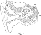
- a normal ear transmits sounds as shown in Figure 1 through the outer ear 101 to the tympanic membrane (eardrum) 102 , which moves the ossicles of the middle ear 103 (malleus, incus, and stapes) that vibrate the oval window and round window openings of the cochlea 104 .
- the cochlea 104 is a long narrow duct wound spirally about its axis for approximately two and a half turns. It includes an upper channel known as the scala vestibuli and a lower channel known as the scala tympani, which are connected by the cochlear duct.
- the cochlea 104 forms an upright spiraling cone with a center called the modiolar where the spiral ganglion cells of the acoustic nerve 105 reside.
- the fluid-filled cochlea 104 functions as a transducer to generate electric pulses which are transmitted to the cochlear nerve 105 , and ultimately to the brain.
- Figure 2 shows the ossicles of the middle ear in greater anatomical detail where the malleus 202 ("hammer") is attached to the inside of the tympanic membrane 201 .
- the outer ear funnels sound in to the tympanic membrane 201 causing it to vibrate. That vibration is felt by the malleus 202 which conducts it through the incus 203 to the stapes 204 , in the process amplifying the vibrations over 20 times.
- the stapes 204 connects to the incus 203 at a stapes head 2041 at the end of the stapes neck 2042 .
- the sound vibrations pass through the anterior crus 2043 and posterior crus 2044 to the stapes foot plate 2045 .
- the stapes foot plate 2045 engages the oval window membrane 205 which transmits the vibrations into the fluid-filled interior of the cochlea for perception as sound.
- Hearing is impaired when there are problems in the ability to transduce external sounds into meaningful action potentials along the neural substrate of the cochlea 104 .
- auditory prostheses have been developed.
- a conventional hearing aid may be used to provide acoustic-mechanical stimulation to the auditory system in the form of amplified sound.
- Middle ear implants also have been developed that employ electromagnetic transducers to mechanically stimulate the structures of the middle ear 103.
- passive middle ear implants which are structures that replace some or all of the ossicular chain to perform the required sound transmission and amplification to deliver the sound vibrations of the tympanic membrane across the oval window membrane into the cochlea.
- U.S. Patent 8,936,637 shows a middle ear prosthesis with a U-shaped attaching mechanism with attachment legs 24' and 24".
- U.S. Patent 8,518,112 also has such attachment legs 21 and 21".
- WO 98/16175 describes a passive middle ear prosthesis with a bell shaped attachment clip 1'.
- U.S. Patent Application Publication 2011/00178364 shows an ossicular replacement prosthesis.
- Embodiments of the present invention are directed to a middle ear prosthesis is made of a stiff deformable material (e.g., thin metal) and includes a planar head end with a central portion having a central diameter.
- the head end is adapted for engagement with a tympanic membrane from the middle ear of an implanted patient.
- An opposing pair of U-shaped stapes engagement legs bend down from the central portion so that an end distance between ends of the engagement legs is less than the central diameter.
- the engagement legs are adapted for adjustable length engagement with the stapes in the middle ear of the implanted patient.
- the head end and the engagement legs are adapted to transmit vibrations from the tympanic membrane to the stapes for perception as sound by the implanted patient.
- the central portion may be thicker than other portions of the prosthesis and/or the engagement legs may be thinner than other portions of the prosthesis.
- the engagement legs may have a straight shape or a zig-zag shape.
- the u-shape of the engagement legs may have an opening that is either smaller or larger than the thickness of a portion of the stapes where engaged by the engagement legs.
- the engagement legs also may include leg end connectors at a distal end of each engagement leg that are adapted to connect corresponding ends of the opposing pair of engagement legs.
- Specific embodiments may include a head end with opposing wings connected to and extending from the central portion.
- the opposing wings may include deformable wing extensions adapted for fixation of the head end at the tympanic membrane.
- the wing extensions include extension end connectors that are adapted to connect opposing extension ends.
- Embodiments of the present invention also include a method of forming a middle ear prosthesis that includes providing a planar sheet of stiff deformable material having a central portion connected to an opposing pair of U-shaped stapes engagement legs.
- the stapes engagement legs are then bent down from the planar sheet towards each other so that an end distance between ends of the engagement legs is less than the central diameter so as to adapt the engagement legs for engagement with the stapes of an implanted patient, and to leave a remaining portion of the planar sheet to form a head end adapted for engagement with the tympanic membrane from the middle ear of an implanted patient.
- the material may be thin metal material.
- Providing the planar sheet may include using micro-laser cutting to shape the planar sheet.
- the planar sheet may be less than 0.2 mm thick.
- the planar sheet may have a uniform thickness, or a non-uniform thickness. Bending the stapes engagement legs down from the planar sheet towards each other may place leg ends of the opposing pair of engagement legs closer to each other than a distance across the central portion where connected to the opposing pair of engagement legs.
- Embodiments of the present invention are directed to a passive middle ear prosthesis (MEP) and corresponding method of producing such a MEP, which replaces a portion of the ossicular chain in the middle ear (at least the incus) and is placed between the tympanic membrane and at least a portion of the stapes.
- the dimensions of the middle ear may vary from patient to patient, so the MEP has a length adaptation mechanism to provide for adjustable length engagement with the stapes.
- FIGS 3A-3E show various views of a passive middle ear prosthesis (MEP) 300 according to an embodiment of the present invention.
- the MEP 300 is formed by initially providing a planar sheet of stiff deformable material as shown in Fig. 3A with a central portion 302 connected to an opposing pair of U-shaped stapes engagement legs 303. In each such pair, the engagement legs 303 are substantially parallel to each other.
- a head end 301 of the MEP 300 extends out from the central portion 302 including a pair of opposing head wings.
- the specific forms of different embodiments of the initial planar sheet for the MEP 300 can be achieved by various known techniques such as by etching, micro-laser cutting, perforating, mechanical cutting, etc.
- the thickness of the initial planar sheet as shown in Fig. 3A should be less than 0.2 mm, for example, between 0.15 mm and 0.1 mm.
- a thinner material results in a more flexible MEP 300, and consequently, the less risk of trauma to tissue in the middle ear, especially from the ends of the engagement legs 303 (see below).
- the material may have a uniform thickness, while in other specific embodiments, the material may have a non-uniform thickness; for example, the central portion 302 may be thicker than other portions of the MEP 300 and/or the engagement legs 303 may be thinner than other portions of the MEP 300.
- the stapes engagement legs 303 are then bent down from the planar sheet towards each other, as shown in Figure 3B , so that an end distance between ends of the engagement legs 303 is less than the central diameter of the central portion 302, as shown in Fig. 3C , so as to adapt the engagement legs 303 for adjustable length engagement with the stapes of an implanted patient (as explained below).
- the remaining portion of the planar sheet forms a head end 301 with the central portion 302 that is adapted for engagement with the tympanic membrane from the middle ear of an implanted patient.
- the head end 301 and the engagement legs 303 are adapted to transmit vibrations from the tympanic membrane to the stapes for perception as sound by the implanted patient.
- the engagement legs 303 have a straight shape.
- Figs. 3D-3E show an alternative embodiment where the engagement legs 303 have a zig-zag shape.
- Each U-shaped pair of engagement legs 303 is flat and may be adjusted/oriented independently of the other pair.
- the U-shape of the engagement legs 303 may have an opening that is either a bit smaller or a bit larger than the thickness of the stapes where it is engaged by the legs.
- the MEP 300 is designed such that the distance between each of the engagement legs 300 in a given U-shaped pair is comparable to the thickness of the portion of the stapes over which the engagement legs 303 are moved-i.e., the stapes neck 2042 and possibly the anterior and posterior crus.
- the U-shape and the thinness of the engagement legs 303 provides some flexibility such that a bias load after insertion of the MEP 300 can translate into a widening of the U shape, thus reducing the bias load onto the stapes foot plate and, consequently, onto the oval window membrane.
- the MEP 300 still can be attached sufficiently to the stapes 204 because the viscous environment (body fluids) surrounding the stapes 204 provides sufficient adhesion force between MEP 300 and stapes tissue to maintain the MEP 300 in place. Then sometime after implantation, tissue grows over the implanted MEP 300 further securing it in place.
- Existing middle ear prostheses for a comparable purpose e.g., prostheses from the TTP-VARIC or TTP-VARIO system of Heinz Kurz GmbH Medizintechnik
- the surgeon has to use a sizer to assess the required length for the prosthesis for a given specific patient. If the surgeon for whatever reason doesn't choose the best prosthesis out of the set, there can be a bias load on the stapes foot plate after implantation because the length of the middle ear chain of ear drum-prosthesis-stapes does not adequately match the natural distance between ear drum and stapes.
- Such a bias load on the stapes foot plate can traumatize the membrane of the oval window leading to a permanent loss of flexibility and, consequently, to some further degree of conductive hearing loss.
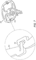
- the relatively long engagement legs 303 as used in embodiments of the present invention advantageously provides a means of intra-operative length adjustment to accommodate the varying distances between the tympanic membrane and the oval window membrane in different specific patients.
- the MEP 300 can be partially fit over the neck 2042 of stapes 204 to provide for a relatively large distance between the tympanic membrane and the oval window membrane.
- Figure 4B shows a case where the MEP 300 fits more deeply over the stapes 204 to accommodate a relatively short distance between the tympanic membrane and the oval window membrane.
- the engagement legs 303 After moving the MEP 300 into its desired position, the engagement legs 303 also may be slightly compressed at or near their open ends by use of an appropriate surgical instrument in order to further fixate them in their position. For such functionality, it may be useful for the engagement legs 303 to have a zig-zag shape (as shown in Figures 3D-3E ) to facilitate the fixation of the engagement legs 303 at the stapes 204 (e.g., at the posterior and anterior crus of the stapes 204 ). A typical distance between two adjacent maximum points of the zig-zag shape usefully may be, for example, 0.5 mm, and between maximum and minimum points of the zig-zag shape, 0.4 mm. As shown in Figure 5 , the engagement legs 303 also may include leg end connectors 500 at a distal end of each engagement leg 303 that are adapted to connect corresponding ends of the opposing pair of engagement legs 303.
- Figures 6A-6B show another embodiment of a middle ear prosthesis 300 with deformable wing extensions 600 on the head end 301 adapted for fixation of the head end 301 at the tympanic membrane.
- Figure 7 shows a further such embodiment with wing extension end connectors 700 that are adapted to connect opposing ends of the wing extensions 600 by a snap-in mechanism which can be released again.
- Figures 8A-8B an embodiment of a MEP 300 where the head end 301 includes extended deformable wings 800 which are bendable extension elements which are bent into final position after bending the extension legs 300.
Description
- The present invention relates to medical implants, and more specifically to a novel ossicular prosthesis arrangement.
- A normal ear transmits sounds as shown in
Figure 1 through theouter ear 101 to the tympanic membrane (eardrum) 102, which moves the ossicles of the middle ear 103 (malleus, incus, and stapes) that vibrate the oval window and round window openings of thecochlea 104. Thecochlea 104 is a long narrow duct wound spirally about its axis for approximately two and a half turns. It includes an upper channel known as the scala vestibuli and a lower channel known as the scala tympani, which are connected by the cochlear duct. Thecochlea 104 forms an upright spiraling cone with a center called the modiolar where the spiral ganglion cells of theacoustic nerve 105 reside. In response to received sounds transmitted by themiddle ear 103, the fluid-filledcochlea 104 functions as a transducer to generate electric pulses which are transmitted to thecochlear nerve 105, and ultimately to the brain. -
Figure 2 shows the ossicles of the middle ear in greater anatomical detail where the malleus 202 ("hammer") is attached to the inside of thetympanic membrane 201. The outer ear funnels sound in to thetympanic membrane 201 causing it to vibrate. That vibration is felt by themalleus 202 which conducts it through theincus 203 to thestapes 204, in the process amplifying the vibrations over 20 times. Thestapes 204 connects to theincus 203 at astapes head 2041 at the end of thestapes neck 2042. The sound vibrations pass through theanterior crus 2043 andposterior crus 2044 to thestapes foot plate 2045. Thestapes foot plate 2045 engages theoval window membrane 205 which transmits the vibrations into the fluid-filled interior of the cochlea for perception as sound. - Hearing is impaired when there are problems in the ability to transduce external sounds into meaningful action potentials along the neural substrate of the
cochlea 104. To improve impaired hearing, auditory prostheses have been developed. For example, when the impairment is related to operation of themiddle ear 103, a conventional hearing aid may be used to provide acoustic-mechanical stimulation to the auditory system in the form of amplified sound. Middle ear implants also have been developed that employ electromagnetic transducers to mechanically stimulate the structures of themiddle ear 103. - In addition to such active hearing devices, there also are passive middle ear implants, which are structures that replace some or all of the ossicular chain to perform the required sound transmission and amplification to deliver the sound vibrations of the tympanic membrane across the oval window membrane into the cochlea.
U.S. Patent 8,936,637 shows a middle ear prosthesis with a U-shaped attaching mechanism with attachment legs 24' and 24". Similarly,U.S. Patent 8,518,112 also has such attachment legs 21 and 21".WO 98/16175 U.S. Patent Application Publication 2011/00178364 - Embodiments of the present invention are directed to a middle ear prosthesis is made of a stiff deformable material (e.g., thin metal) and includes a planar head end with a central portion having a central diameter. The head end is adapted for engagement with a tympanic membrane from the middle ear of an implanted patient. An opposing pair of U-shaped stapes engagement legs bend down from the central portion so that an end distance between ends of the engagement legs is less than the central diameter. The engagement legs are adapted for adjustable length engagement with the stapes in the middle ear of the implanted patient. The head end and the engagement legs are adapted to transmit vibrations from the tympanic membrane to the stapes for perception as sound by the implanted patient.
- The central portion may be thicker than other portions of the prosthesis and/or the engagement legs may be thinner than other portions of the prosthesis. The engagement legs may have a straight shape or a zig-zag shape. The u-shape of the engagement legs may have an opening that is either smaller or larger than the thickness of a portion of the stapes where engaged by the engagement legs. The engagement legs also may include leg end connectors at a distal end of each engagement leg that are adapted to connect corresponding ends of the opposing pair of engagement legs.
- Specific embodiments may include a head end with opposing wings connected to and extending from the central portion. The opposing wings may include deformable wing extensions adapted for fixation of the head end at the tympanic membrane. And the wing extensions include extension end connectors that are adapted to connect opposing extension ends.
- Embodiments of the present invention also include a method of forming a middle ear prosthesis that includes providing a planar sheet of stiff deformable material having a central portion connected to an opposing pair of U-shaped stapes engagement legs. The stapes engagement legs are then bent down from the planar sheet towards each other so that an end distance between ends of the engagement legs is less than the central diameter so as to adapt the engagement legs for engagement with the stapes of an implanted patient, and to leave a remaining portion of the planar sheet to form a head end adapted for engagement with the tympanic membrane from the middle ear of an implanted patient.
- In further specific embodiments, the material may be thin metal material. Providing the planar sheet may include using micro-laser cutting to shape the planar sheet. The planar sheet may be less than 0.2 mm thick. The planar sheet may have a uniform thickness, or a non-uniform thickness. Bending the stapes engagement legs down from the planar sheet towards each other may place leg ends of the opposing pair of engagement legs closer to each other than a distance across the central portion where connected to the opposing pair of engagement legs.
-
-
Figure 1 shows various anatomical structures of a normal human ear. -
Figure 2 shows details of the anatomy of the ossicles in the middle ear. -
Figures 3A-3E show various views of a passive middle ear prosthesis according to an embodiment of the present invention. -
Figures 4A-4B show how a middle ear prosthesis according to an embodiment of the present invention engages the stapes in an implanted patient. -
Figure 5 shows structural details of leg end connectors according to an embodiment of the present invention. -
Figures 6A-6B show an embodiment of a middle ear prosthesis with wing extensions on the head end. -
Figure 7 shows an embodiment with wing extension connectors. -
Figures 8A-8B show an embodiment with extended deformable wings. - Embodiments of the present invention are directed to a passive middle ear prosthesis (MEP) and corresponding method of producing such a MEP, which replaces a portion of the ossicular chain in the middle ear (at least the incus) and is placed between the tympanic membrane and at least a portion of the stapes. The dimensions of the middle ear may vary from patient to patient, so the MEP has a length adaptation mechanism to provide for adjustable length engagement with the stapes.
-
Figures 3A-3E show various views of a passive middle ear prosthesis (MEP) 300 according to an embodiment of the present invention. TheMEP 300 is formed by initially providing a planar sheet of stiff deformable material as shown inFig. 3A with acentral portion 302 connected to an opposing pair of U-shapedstapes engagement legs 303. In each such pair, theengagement legs 303 are substantially parallel to each other. Ahead end 301 of the MEP 300 extends out from thecentral portion 302 including a pair of opposing head wings. The specific forms of different embodiments of the initial planar sheet for theMEP 300 can be achieved by various known techniques such as by etching, micro-laser cutting, perforating, mechanical cutting, etc. - Given the application as a middle ear prosthesis, the thickness of the initial planar sheet as shown in
Fig. 3A should be less than 0.2 mm, for example, between 0.15 mm and 0.1 mm. A thinner material results in a moreflexible MEP 300, and consequently, the less risk of trauma to tissue in the middle ear, especially from the ends of the engagement legs 303 (see below). In some specific embodiments, the material may have a uniform thickness, while in other specific embodiments, the material may have a non-uniform thickness; for example, thecentral portion 302 may be thicker than other portions of theMEP 300 and/or theengagement legs 303 may be thinner than other portions of theMEP 300. - The
stapes engagement legs 303 are then bent down from the planar sheet towards each other, as shown inFigure 3B , so that an end distance between ends of theengagement legs 303 is less than the central diameter of thecentral portion 302, as shown inFig. 3C , so as to adapt theengagement legs 303 for adjustable length engagement with the stapes of an implanted patient (as explained below). After bending, the remaining portion of the planar sheet forms ahead end 301 with thecentral portion 302 that is adapted for engagement with the tympanic membrane from the middle ear of an implanted patient. Thehead end 301 and theengagement legs 303 are adapted to transmit vibrations from the tympanic membrane to the stapes for perception as sound by the implanted patient. - In the specific embodiment shown in
Figs. 3A-3C , theengagement legs 303 have a straight shape.Figs. 3D-3E show an alternative embodiment where theengagement legs 303 have a zig-zag shape. Each U-shaped pair ofengagement legs 303 is flat and may be adjusted/oriented independently of the other pair. - The U-shape of the
engagement legs 303 may have an opening that is either a bit smaller or a bit larger than the thickness of the stapes where it is engaged by the legs. TheMEP 300 is designed such that the distance between each of theengagement legs 300 in a given U-shaped pair is comparable to the thickness of the portion of the stapes over which theengagement legs 303 are moved-i.e., thestapes neck 2042 and possibly the anterior and posterior crus. When this distance between pairedengagement legs 303 is slightly smaller than thickness of thestapes 204 over which they pass, the U-shape and the thinness of theengagement legs 303 provides some flexibility such that a bias load after insertion of theMEP 300 can translate into a widening of the U shape, thus reducing the bias load onto the stapes foot plate and, consequently, onto the oval window membrane. In the alternative case when distance between theengagement legs 303 of a given pair is slightly larger than the dimension of the engaged portions of thestapes 204, it surprisingly turns out that theMEP 300 still can be attached sufficiently to thestapes 204 because the viscous environment (body fluids) surrounding thestapes 204 provides sufficient adhesion force betweenMEP 300 and stapes tissue to maintain theMEP 300 in place. Then sometime after implantation, tissue grows over the implantedMEP 300 further securing it in place. - Existing middle ear prostheses for a comparable purpose (e.g., prostheses from the TTP-VARIC or TTP-VARIO system of Heinz Kurz GmbH Medizintechnik) are provided in form of a set of multiple prostheses each having different lengths. The surgeon has to use a sizer to assess the required length for the prosthesis for a given specific patient. If the surgeon for whatever reason doesn't choose the best prosthesis out of the set, there can be a bias load on the stapes foot plate after implantation because the length of the middle ear chain of ear drum-prosthesis-stapes does not adequately match the natural distance between ear drum and stapes. Such a bias load on the stapes foot plate can traumatize the membrane of the oval window leading to a permanent loss of flexibility and, consequently, to some further degree of conductive hearing loss.
- By contrast, the relatively
long engagement legs 303 as used in embodiments of the present invention advantageously provides a means of intra-operative length adjustment to accommodate the varying distances between the tympanic membrane and the oval window membrane in different specific patients. As shown inFigure 4A , theMEP 300 can be partially fit over theneck 2042 ofstapes 204 to provide for a relatively large distance between the tympanic membrane and the oval window membrane.Figure 4B shows a case where theMEP 300 fits more deeply over thestapes 204 to accommodate a relatively short distance between the tympanic membrane and the oval window membrane. - After moving the
MEP 300 into its desired position, theengagement legs 303 also may be slightly compressed at or near their open ends by use of an appropriate surgical instrument in order to further fixate them in their position. For such functionality, it may be useful for theengagement legs 303 to have a zig-zag shape (as shown inFigures 3D-3E ) to facilitate the fixation of theengagement legs 303 at the stapes 204 (e.g., at the posterior and anterior crus of the stapes 204). A typical distance between two adjacent maximum points of the zig-zag shape usefully may be, for example, 0.5 mm, and between maximum and minimum points of the zig-zag shape, 0.4 mm. As shown inFigure 5 , theengagement legs 303 also may includeleg end connectors 500 at a distal end of eachengagement leg 303 that are adapted to connect corresponding ends of the opposing pair ofengagement legs 303. -
Figures 6A-6B show another embodiment of amiddle ear prosthesis 300 withdeformable wing extensions 600 on thehead end 301 adapted for fixation of thehead end 301 at the tympanic membrane.Figure 7 shows a further such embodiment with wingextension end connectors 700 that are adapted to connect opposing ends of thewing extensions 600 by a snap-in mechanism which can be released again. As shown inFigures 8A-8B , an embodiment of aMEP 300 where thehead end 301 includes extendeddeformable wings 800 which are bendable extension elements which are bent into final position after bending theextension legs 300. - Although various exemplary embodiments of the invention have been disclosed, various changes and modifications can be made which will achieve some of the advantages of the invention without departing from the true scope of the invention as defined by the appended claims.
Claims (15)
- A middle ear prosthesis made of a stiff deformable material and comprising:a planar head end with a central portion having a central diameter, wherein the head end is adapted for engagement with a tympanic membrane from the middle ear of an implanted patient; andan opposing pair of U-shaped stapes engagement legs bending down from the central portion so that an end distance between ends of the engagement legs is less than the central diameter; wherein the engagement legs are adapted for adjustable length engagement with the stapes in the middle ear of the implanted patient;wherein the head end and the engagement legs are adapted to transmit vibrations from the tympanic membrane to the stapes for perception as sound by the implanted patient.
- The prosthesis according to claim 1, wherein the material is thin metal material.
- The prosthesis according to claim 1 or claim 2, wherein the central portion is thicker than other portions of the prosthesis.
- The prosthesis according to any one of the preceding claims, wherein the engagement legs are thinner than other portions of the prosthesis.
- The prosthesis according to any one of the preceding claims, wherein the engagement legs have a straight shape.
- The prosthesis according to any one of claims 1 to 4, wherein the engagement legs have a zig-zag shape.
- The prosthesis according to any one of the preceding claims, wherein the u-shape of the engagement legs has an opening smaller than the thickness of a portion of the stapes where engaged by the engagement legs.
- The prosthesis according to any one of claims 1 to 6, wherein the u-shape of the engagement legs has an opening larger than the thickness of a portion of the stapes where engaged by the engagement legs.
- The prosthesis according to any one of the preceding claims, wherein the engagement legs include leg end connectors at a distal end of each engagement leg adapted to connect corresponding ends of the opposing pair of engagement legs.
- The prosthesis according to any one of the preceding claims, wherein the head end comprises opposing wings connected to and extending from the central portion.
- The prosthesis according to claim 10, wherein the opposing wings include deformable wing extensions adapted for fixation of the head end at the tympanic membrane.
- The prosthesis according to claim 11, wherein the wing extensions include extension end connectors adapted to connect opposing extension ends.
- A method of forming a middle ear prosthesis comprising:providing a planar sheet of stiff deformable material having a central portion with a central diameter, wherein the central portion is connected to an opposing pair of U-shaped stapes engagement legs; andbending the stapes engagement legs down from the planar sheet towards each other so that an end distance between ends of the engagement legs is less than the central diameter so as to adapt the engagement legs for adjustable length engagement with the stapes of an implanted patient, and to leave a remaining portion of the planar sheet to form a head end adapted for engagement with the tympanic membrane from the middle ear of an implanted patient.
- The method according to claim 13, wherein the material is thin metal material.
- The method according to claim 13 or claim 14, wherein providing the planar sheet includes using micro-laser cutting to shape the planar sheet.
Applications Claiming Priority (2)
| Application Number | Priority Date | Filing Date | Title |
|---|---|---|---|
| US201662393696P | 2016-09-13 | 2016-09-13 | |
| PCT/US2017/051047 WO2018052866A1 (en) | 2016-09-13 | 2017-09-12 | Passive middle ear prosthesis |
Publications (3)
| Publication Number | Publication Date |
|---|---|
| EP3512463A1 EP3512463A1 (en) | 2019-07-24 |
| EP3512463A4 EP3512463A4 (en) | 2019-10-16 |
| EP3512463B1 true EP3512463B1 (en) | 2020-04-22 |
Family
ID=61619746
Family Applications (1)
| Application Number | Title | Priority Date | Filing Date |
|---|---|---|---|
| EP17851383.4A Active EP3512463B1 (en) | 2016-09-13 | 2017-09-12 | Passive middle ear prosthesis |
Country Status (5)
| Country | Link |
|---|---|
| US (1) | US10888418B2 (en) |
| EP (1) | EP3512463B1 (en) |
| CN (1) | CN109688976B (en) |
| AU (1) | AU2017327850B2 (en) |
| WO (1) | WO2018052866A1 (en) |
Cited By (1)
| Publication number | Priority date | Publication date | Assignee | Title |
|---|---|---|---|---|
| EP3954328A1 (en) | 2020-08-13 | 2022-02-16 | MED-EL Elektromedizinische Geräte GmbH | Ossicular prosthesis |
Families Citing this family (7)
| Publication number | Priority date | Publication date | Assignee | Title |
|---|---|---|---|---|
| US10646331B2 (en) * | 2017-04-26 | 2020-05-12 | University Of Maryland, Baltimore | Ossicular prosthesis and method and system for manufacturing same |
| DE102017115806B3 (en) * | 2017-07-13 | 2018-08-30 | Heinz Kurz Gmbh | Self-clamping head plate for a ossicle prosthesis and auditory ossicle prosthesis |
| DE102020108887A1 (en) * | 2020-03-31 | 2021-09-30 | Med-El Elektromedizinische Geräte GmbH | Length-adjustable ossicular prosthesis |
| USD994885S1 (en) * | 2021-01-15 | 2023-08-08 | Grace Medical Group, Inc. | Ossicular prosthesis |
| RU2766413C1 (en) * | 2021-04-23 | 2022-03-15 | Общество с ограниченной ответственностью "КОНМЕТ" | Implant as a prosthesis of the auditory ossicles to replace damaged parts of the middle ear |
| IL285583A (en) | 2021-08-12 | 2022-07-01 | J N Medical | Ossicular replacement prosthesis with controllable stapedial conforming function, manufacture method thereof and applicator device therefor |
| DE202022103367U1 (en) * | 2022-06-15 | 2022-09-23 | Heinz Kurz Gmbh | Length-adjustable auditory ossicle prosthesis with in-situ elongation from the head plate |
Family Cites Families (16)
| Publication number | Priority date | Publication date | Assignee | Title |
|---|---|---|---|---|
| DE19744789C2 (en) | 1996-10-12 | 2002-05-08 | Univ Dresden Tech | Ossicular prosthesis for sound transmission in the middle ear |
| WO1998016175A1 (en) | 1996-10-12 | 1998-04-23 | Technische Universität Dresden | Ossicle prosthesis for sound transmission in the middle ear |
| DE20014659U1 (en) | 2000-08-24 | 2000-11-30 | Heinz Kurz Gmbh Medizintechnik | Coupling device |
| US7955386B2 (en) * | 2003-09-19 | 2011-06-07 | Clarity Corporation | Middle ear prosthesis |
| DE102007013708B3 (en) * | 2007-03-22 | 2008-01-31 | Heinz Kurz Gmbh Medizintechnik | Ossicular prosthesis for member or parts of member of ossicular chain, has bar elements which are geometrically so arranged that it follows with local medial movement of ear-drum of these medial movement |
| WO2009056167A1 (en) * | 2007-10-30 | 2009-05-07 | 3Win N.V. | Body-worn wireless transducer module |
| DE102007062151B3 (en) | 2007-12-21 | 2008-12-24 | Heinz Kurz Gmbh Medizintechnik | Modular Middle Ear Full Prosthesis |
| DE102008015115A1 (en) * | 2008-03-20 | 2009-10-01 | Heinz Kurz Gmbh Medizintechnik | Auditory ossicle prosthesis with variable attachment surfaces |
| DE102009016468B3 (en) | 2009-04-10 | 2009-12-24 | Heinz Kurz Gmbh Medizintechnik | Ossicular prosthesis for replacing or bridging element of human ossicular chain, has partial branches deformable permanently and plastically, and folded into multiple straps transverse to longitudinal axis, before deformation of branches |
| US9544700B2 (en) * | 2009-06-15 | 2017-01-10 | Earlens Corporation | Optically coupled active ossicular replacement prosthesis |
| EP2583639B1 (en) | 2010-01-21 | 2014-06-25 | MED-EL Elektromedizinische Geraete GmbH | Incus replacement partial ossicular replacement prosthesis |
| DE202011052221U1 (en) | 2011-12-07 | 2012-01-16 | Heinz Kurz Gmbh Medizintechnik | Length variable passive ossicle prosthesis |
| EP2803334B1 (en) | 2013-05-17 | 2022-04-27 | Franco Beoni | Prosthetic element for connecting the stapes footplate to a middle ear ossicular prosthesis |
| DE102013106574A1 (en) | 2013-06-24 | 2014-12-24 | Heinz Kurz Gmbh Medizintechnik | Ossicular prosthesis with CT or MRI markers |
| CN107113515B (en) * | 2014-11-12 | 2019-04-30 | Med-El电气医疗器械有限公司 | Processus brevis incudis attachment for implanted floating converter |
| DE102014119224B3 (en) * | 2014-12-19 | 2016-01-28 | Heinz Kurz Gmbh Medizintechnik | Auditory ossicle prosthesis with spikes |
-
2017
- 2017-09-12 EP EP17851383.4A patent/EP3512463B1/en active Active
- 2017-09-12 WO PCT/US2017/051047 patent/WO2018052866A1/en unknown
- 2017-09-12 CN CN201780055268.7A patent/CN109688976B/en active Active
- 2017-09-12 US US16/327,883 patent/US10888418B2/en active Active
- 2017-09-12 AU AU2017327850A patent/AU2017327850B2/en active Active
Non-Patent Citations (1)
| Title |
|---|
| None * |
Cited By (2)
| Publication number | Priority date | Publication date | Assignee | Title |
|---|---|---|---|---|
| EP3954328A1 (en) | 2020-08-13 | 2022-02-16 | MED-EL Elektromedizinische Geräte GmbH | Ossicular prosthesis |
| WO2022033736A1 (en) | 2020-08-13 | 2022-02-17 | Med-El Elektromedizinische Geräte GmbH | Ossicular prosthesis |
Also Published As
| Publication number | Publication date |
|---|---|
| US20190201189A1 (en) | 2019-07-04 |
| CN109688976B (en) | 2021-08-10 |
| AU2017327850A1 (en) | 2019-03-14 |
| US10888418B2 (en) | 2021-01-12 |
| CN109688976A (en) | 2019-04-26 |
| WO2018052866A1 (en) | 2018-03-22 |
| EP3512463A4 (en) | 2019-10-16 |
| EP3512463A1 (en) | 2019-07-24 |
| AU2017327850B2 (en) | 2019-08-01 |
Similar Documents
| Publication | Publication Date | Title |
|---|---|---|
| EP3512463B1 (en) | Passive middle ear prosthesis | |
| EP2583639B1 (en) | Incus replacement partial ossicular replacement prosthesis | |
| EP3219114B1 (en) | Incus short process attachment for implantable floating mass transducer | |
| US20120136197A1 (en) | Hearing prosthesis having a flexible elongate energy transfer mechanism | |
| EP2681931B1 (en) | Middle ear implant for otosclerosis | |
| US10244335B2 (en) | Pre-load feedback of a middle-ear coupler | |
| US9191760B2 (en) | Optimal pre-load for floating mass transducers | |
| US10798502B2 (en) | Implantable transducer system | |
| US11553290B2 (en) | Implantable sound sensors with non-uniform diaphragms | |
| US11006229B2 (en) | Middle ear implant coupler for mechanical cochlea stimulation via the round window | |
| EP2689591B1 (en) | Line transmission for vibratory actuation in implantable transducers | |
| US6387038B1 (en) | Air cell mountable support shaft |
Legal Events
| Date | Code | Title | Description |
|---|---|---|---|
| STAA | Information on the status of an ep patent application or granted ep patent |
Free format text: STATUS: THE INTERNATIONAL PUBLICATION HAS BEEN MADE |
|
| PUAI | Public reference made under article 153(3) epc to a published international application that has entered the european phase |
Free format text: ORIGINAL CODE: 0009012 |
|
| STAA | Information on the status of an ep patent application or granted ep patent |
Free format text: STATUS: REQUEST FOR EXAMINATION WAS MADE |
|
| 17P | Request for examination filed |
Effective date: 20190219 |
|
| AK | Designated contracting states |
Kind code of ref document: A1 Designated state(s): AL AT BE BG CH CY CZ DE DK EE ES FI FR GB GR HR HU IE IS IT LI LT LU LV MC MK MT NL NO PL PT RO RS SE SI SK SM TR |
|
| AX | Request for extension of the european patent |
Extension state: BA ME |
|
| A4 | Supplementary search report drawn up and despatched |
Effective date: 20190912 |
|
| RIC1 | Information provided on ipc code assigned before grant |
Ipc: A61F 2/18 20060101AFI20190906BHEP |
|
| GRAP | Despatch of communication of intention to grant a patent |
Free format text: ORIGINAL CODE: EPIDOSNIGR1 |
|
| STAA | Information on the status of an ep patent application or granted ep patent |
Free format text: STATUS: GRANT OF PATENT IS INTENDED |
|
| RIC1 | Information provided on ipc code assigned before grant |
Ipc: A61F 2/18 20060101AFI20191029BHEP |
|
| DAV | Request for validation of the european patent (deleted) | ||
| DAX | Request for extension of the european patent (deleted) | ||
| INTG | Intention to grant announced |
Effective date: 20191122 |
|
| GRAS | Grant fee paid |
Free format text: ORIGINAL CODE: EPIDOSNIGR3 |
|
| GRAA | (expected) grant |
Free format text: ORIGINAL CODE: 0009210 |
|
| STAA | Information on the status of an ep patent application or granted ep patent |
Free format text: STATUS: THE PATENT HAS BEEN GRANTED |
|
| AK | Designated contracting states |
Kind code of ref document: B1 Designated state(s): AL AT BE BG CH CY CZ DE DK EE ES FI FR GB GR HR HU IE IS IT LI LT LU LV MC MK MT NL NO PL PT RO RS SE SI SK SM TR |
|
| REG | Reference to a national code |
Ref country code: CH Ref legal event code: EP |
|
| REG | Reference to a national code |
Ref country code: IE Ref legal event code: FG4D |
|
| REG | Reference to a national code |
Ref country code: DE Ref legal event code: R096 Ref document number: 602017015422 Country of ref document: DE |
|
| REG | Reference to a national code |
Ref country code: AT Ref legal event code: REF Ref document number: 1259088 Country of ref document: AT Kind code of ref document: T Effective date: 20200515 |
|
| REG | Reference to a national code |
Ref country code: NL Ref legal event code: FP |
|
| REG | Reference to a national code |
Ref country code: LT Ref legal event code: MG4D |
|
| PG25 | Lapsed in a contracting state [announced via postgrant information from national office to epo] |
Ref country code: NO Free format text: LAPSE BECAUSE OF FAILURE TO SUBMIT A TRANSLATION OF THE DESCRIPTION OR TO PAY THE FEE WITHIN THE PRESCRIBED TIME-LIMIT Effective date: 20200722 Ref country code: PT Free format text: LAPSE BECAUSE OF FAILURE TO SUBMIT A TRANSLATION OF THE DESCRIPTION OR TO PAY THE FEE WITHIN THE PRESCRIBED TIME-LIMIT Effective date: 20200824 Ref country code: FI Free format text: LAPSE BECAUSE OF FAILURE TO SUBMIT A TRANSLATION OF THE DESCRIPTION OR TO PAY THE FEE WITHIN THE PRESCRIBED TIME-LIMIT Effective date: 20200422 Ref country code: LT Free format text: LAPSE BECAUSE OF FAILURE TO SUBMIT A TRANSLATION OF THE DESCRIPTION OR TO PAY THE FEE WITHIN THE PRESCRIBED TIME-LIMIT Effective date: 20200422 Ref country code: IS Free format text: LAPSE BECAUSE OF FAILURE TO SUBMIT A TRANSLATION OF THE DESCRIPTION OR TO PAY THE FEE WITHIN THE PRESCRIBED TIME-LIMIT Effective date: 20200822 Ref country code: SE Free format text: LAPSE BECAUSE OF FAILURE TO SUBMIT A TRANSLATION OF THE DESCRIPTION OR TO PAY THE FEE WITHIN THE PRESCRIBED TIME-LIMIT Effective date: 20200422 Ref country code: GR Free format text: LAPSE BECAUSE OF FAILURE TO SUBMIT A TRANSLATION OF THE DESCRIPTION OR TO PAY THE FEE WITHIN THE PRESCRIBED TIME-LIMIT Effective date: 20200723 |
|
| REG | Reference to a national code |
Ref country code: AT Ref legal event code: MK05 Ref document number: 1259088 Country of ref document: AT Kind code of ref document: T Effective date: 20200422 |
|
| PG25 | Lapsed in a contracting state [announced via postgrant information from national office to epo] |
Ref country code: RS Free format text: LAPSE BECAUSE OF FAILURE TO SUBMIT A TRANSLATION OF THE DESCRIPTION OR TO PAY THE FEE WITHIN THE PRESCRIBED TIME-LIMIT Effective date: 20200422 Ref country code: BG Free format text: LAPSE BECAUSE OF FAILURE TO SUBMIT A TRANSLATION OF THE DESCRIPTION OR TO PAY THE FEE WITHIN THE PRESCRIBED TIME-LIMIT Effective date: 20200722 Ref country code: LV Free format text: LAPSE BECAUSE OF FAILURE TO SUBMIT A TRANSLATION OF THE DESCRIPTION OR TO PAY THE FEE WITHIN THE PRESCRIBED TIME-LIMIT Effective date: 20200422 Ref country code: HR Free format text: LAPSE BECAUSE OF FAILURE TO SUBMIT A TRANSLATION OF THE DESCRIPTION OR TO PAY THE FEE WITHIN THE PRESCRIBED TIME-LIMIT Effective date: 20200422 |
|
| PG25 | Lapsed in a contracting state [announced via postgrant information from national office to epo] |
Ref country code: AL Free format text: LAPSE BECAUSE OF FAILURE TO SUBMIT A TRANSLATION OF THE DESCRIPTION OR TO PAY THE FEE WITHIN THE PRESCRIBED TIME-LIMIT Effective date: 20200422 |
|
| REG | Reference to a national code |
Ref country code: DE Ref legal event code: R097 Ref document number: 602017015422 Country of ref document: DE |
|
| PG25 | Lapsed in a contracting state [announced via postgrant information from national office to epo] |
Ref country code: SM Free format text: LAPSE BECAUSE OF FAILURE TO SUBMIT A TRANSLATION OF THE DESCRIPTION OR TO PAY THE FEE WITHIN THE PRESCRIBED TIME-LIMIT Effective date: 20200422 Ref country code: EE Free format text: LAPSE BECAUSE OF FAILURE TO SUBMIT A TRANSLATION OF THE DESCRIPTION OR TO PAY THE FEE WITHIN THE PRESCRIBED TIME-LIMIT Effective date: 20200422 Ref country code: CZ Free format text: LAPSE BECAUSE OF FAILURE TO SUBMIT A TRANSLATION OF THE DESCRIPTION OR TO PAY THE FEE WITHIN THE PRESCRIBED TIME-LIMIT Effective date: 20200422 Ref country code: IT Free format text: LAPSE BECAUSE OF FAILURE TO SUBMIT A TRANSLATION OF THE DESCRIPTION OR TO PAY THE FEE WITHIN THE PRESCRIBED TIME-LIMIT Effective date: 20200422 Ref country code: AT Free format text: LAPSE BECAUSE OF FAILURE TO SUBMIT A TRANSLATION OF THE DESCRIPTION OR TO PAY THE FEE WITHIN THE PRESCRIBED TIME-LIMIT Effective date: 20200422 Ref country code: RO Free format text: LAPSE BECAUSE OF FAILURE TO SUBMIT A TRANSLATION OF THE DESCRIPTION OR TO PAY THE FEE WITHIN THE PRESCRIBED TIME-LIMIT Effective date: 20200422 Ref country code: ES Free format text: LAPSE BECAUSE OF FAILURE TO SUBMIT A TRANSLATION OF THE DESCRIPTION OR TO PAY THE FEE WITHIN THE PRESCRIBED TIME-LIMIT Effective date: 20200422 Ref country code: DK Free format text: LAPSE BECAUSE OF FAILURE TO SUBMIT A TRANSLATION OF THE DESCRIPTION OR TO PAY THE FEE WITHIN THE PRESCRIBED TIME-LIMIT Effective date: 20200422 |
|
| PG25 | Lapsed in a contracting state [announced via postgrant information from national office to epo] |
Ref country code: PL Free format text: LAPSE BECAUSE OF FAILURE TO SUBMIT A TRANSLATION OF THE DESCRIPTION OR TO PAY THE FEE WITHIN THE PRESCRIBED TIME-LIMIT Effective date: 20200422 Ref country code: SK Free format text: LAPSE BECAUSE OF FAILURE TO SUBMIT A TRANSLATION OF THE DESCRIPTION OR TO PAY THE FEE WITHIN THE PRESCRIBED TIME-LIMIT Effective date: 20200422 |
|
| PLBE | No opposition filed within time limit |
Free format text: ORIGINAL CODE: 0009261 |
|
| STAA | Information on the status of an ep patent application or granted ep patent |
Free format text: STATUS: NO OPPOSITION FILED WITHIN TIME LIMIT |
|
| 26N | No opposition filed |
Effective date: 20210125 |
|
| REG | Reference to a national code |
Ref country code: CH Ref legal event code: PL |
|
| PG25 | Lapsed in a contracting state [announced via postgrant information from national office to epo] |
Ref country code: SI Free format text: LAPSE BECAUSE OF FAILURE TO SUBMIT A TRANSLATION OF THE DESCRIPTION OR TO PAY THE FEE WITHIN THE PRESCRIBED TIME-LIMIT Effective date: 20200422 |
|
| REG | Reference to a national code |
Ref country code: BE Ref legal event code: MM Effective date: 20200930 |
|
| PG25 | Lapsed in a contracting state [announced via postgrant information from national office to epo] |
Ref country code: LU Free format text: LAPSE BECAUSE OF NON-PAYMENT OF DUE FEES Effective date: 20200912 |
|
| PG25 | Lapsed in a contracting state [announced via postgrant information from national office to epo] |
Ref country code: BE Free format text: LAPSE BECAUSE OF NON-PAYMENT OF DUE FEES Effective date: 20200930 Ref country code: CH Free format text: LAPSE BECAUSE OF NON-PAYMENT OF DUE FEES Effective date: 20200930 Ref country code: LI Free format text: LAPSE BECAUSE OF NON-PAYMENT OF DUE FEES Effective date: 20200930 Ref country code: IE Free format text: LAPSE BECAUSE OF NON-PAYMENT OF DUE FEES Effective date: 20200912 |
|
| PG25 | Lapsed in a contracting state [announced via postgrant information from national office to epo] |
Ref country code: TR Free format text: LAPSE BECAUSE OF FAILURE TO SUBMIT A TRANSLATION OF THE DESCRIPTION OR TO PAY THE FEE WITHIN THE PRESCRIBED TIME-LIMIT Effective date: 20200422 Ref country code: MT Free format text: LAPSE BECAUSE OF FAILURE TO SUBMIT A TRANSLATION OF THE DESCRIPTION OR TO PAY THE FEE WITHIN THE PRESCRIBED TIME-LIMIT Effective date: 20200422 Ref country code: CY Free format text: LAPSE BECAUSE OF FAILURE TO SUBMIT A TRANSLATION OF THE DESCRIPTION OR TO PAY THE FEE WITHIN THE PRESCRIBED TIME-LIMIT Effective date: 20200422 |
|
| PG25 | Lapsed in a contracting state [announced via postgrant information from national office to epo] |
Ref country code: MK Free format text: LAPSE BECAUSE OF FAILURE TO SUBMIT A TRANSLATION OF THE DESCRIPTION OR TO PAY THE FEE WITHIN THE PRESCRIBED TIME-LIMIT Effective date: 20200422 Ref country code: MC Free format text: LAPSE BECAUSE OF FAILURE TO SUBMIT A TRANSLATION OF THE DESCRIPTION OR TO PAY THE FEE WITHIN THE PRESCRIBED TIME-LIMIT Effective date: 20200422 |
|
| PGFP | Annual fee paid to national office [announced via postgrant information from national office to epo] |
Ref country code: NL Payment date: 20230926 Year of fee payment: 7 Ref country code: GB Payment date: 20230926 Year of fee payment: 7 |
|
| PGFP | Annual fee paid to national office [announced via postgrant information from national office to epo] |
Ref country code: FR Payment date: 20230926 Year of fee payment: 7 Ref country code: DE Payment date: 20230928 Year of fee payment: 7 |