EP3512431B1 - Method for imaging a sample with blood and associated devices - Google Patents
Method for imaging a sample with blood and associated devices Download PDFInfo
- Publication number
- EP3512431B1 EP3512431B1 EP17771395.5A EP17771395A EP3512431B1 EP 3512431 B1 EP3512431 B1 EP 3512431B1 EP 17771395 A EP17771395 A EP 17771395A EP 3512431 B1 EP3512431 B1 EP 3512431B1
- Authority
- EP
- European Patent Office
- Prior art keywords
- contribution
- blood
- interest
- diffusors
- imaging
- Prior art date
- Legal status (The legal status is an assumption and is not a legal conclusion. Google has not performed a legal analysis and makes no representation as to the accuracy of the status listed.)
- Active
Links
Images


Classifications
-
- A—HUMAN NECESSITIES
- A61—MEDICAL OR VETERINARY SCIENCE; HYGIENE
- A61B—DIAGNOSIS; SURGERY; IDENTIFICATION
- A61B8/00—Diagnosis using ultrasonic, sonic or infrasonic waves
- A61B8/06—Measuring blood flow
-
- A—HUMAN NECESSITIES
- A61—MEDICAL OR VETERINARY SCIENCE; HYGIENE
- A61B—DIAGNOSIS; SURGERY; IDENTIFICATION
- A61B8/00—Diagnosis using ultrasonic, sonic or infrasonic waves
- A61B8/08—Clinical applications
- A61B8/0891—Clinical applications for diagnosis of blood vessels
-
- A—HUMAN NECESSITIES
- A61—MEDICAL OR VETERINARY SCIENCE; HYGIENE
- A61B—DIAGNOSIS; SURGERY; IDENTIFICATION
- A61B8/00—Diagnosis using ultrasonic, sonic or infrasonic waves
- A61B8/44—Constructional features of the ultrasonic, sonic or infrasonic diagnostic device
- A61B8/4483—Constructional features of the ultrasonic, sonic or infrasonic diagnostic device characterised by features of the ultrasound transducer
- A61B8/4494—Constructional features of the ultrasonic, sonic or infrasonic diagnostic device characterised by features of the ultrasound transducer characterised by the arrangement of the transducer elements
-
- A—HUMAN NECESSITIES
- A61—MEDICAL OR VETERINARY SCIENCE; HYGIENE
- A61B—DIAGNOSIS; SURGERY; IDENTIFICATION
- A61B8/00—Diagnosis using ultrasonic, sonic or infrasonic waves
- A61B8/48—Diagnostic techniques
- A61B8/488—Diagnostic techniques involving Doppler signals
-
- A—HUMAN NECESSITIES
- A61—MEDICAL OR VETERINARY SCIENCE; HYGIENE
- A61B—DIAGNOSIS; SURGERY; IDENTIFICATION
- A61B8/00—Diagnosis using ultrasonic, sonic or infrasonic waves
- A61B8/52—Devices using data or image processing specially adapted for diagnosis using ultrasonic, sonic or infrasonic waves
- A61B8/5207—Devices using data or image processing specially adapted for diagnosis using ultrasonic, sonic or infrasonic waves involving processing of raw data to produce diagnostic data, e.g. for generating an image
-
- G—PHYSICS
- G01—MEASURING; TESTING
- G01S—RADIO DIRECTION-FINDING; RADIO NAVIGATION; DETERMINING DISTANCE OR VELOCITY BY USE OF RADIO WAVES; LOCATING OR PRESENCE-DETECTING BY USE OF THE REFLECTION OR RERADIATION OF RADIO WAVES; ANALOGOUS ARRANGEMENTS USING OTHER WAVES
- G01S15/00—Systems using the reflection or reradiation of acoustic waves, e.g. sonar systems
- G01S15/88—Sonar systems specially adapted for specific applications
- G01S15/89—Sonar systems specially adapted for specific applications for mapping or imaging
- G01S15/8906—Short-range imaging systems; Acoustic microscope systems using pulse-echo techniques
- G01S15/8909—Short-range imaging systems; Acoustic microscope systems using pulse-echo techniques using a static transducer configuration
- G01S15/8915—Short-range imaging systems; Acoustic microscope systems using pulse-echo techniques using a static transducer configuration using a transducer array
- G01S15/8925—Short-range imaging systems; Acoustic microscope systems using pulse-echo techniques using a static transducer configuration using a transducer array the array being a two-dimensional transducer configuration, i.e. matrix or orthogonal linear arrays
-
- G—PHYSICS
- G01—MEASURING; TESTING
- G01S—RADIO DIRECTION-FINDING; RADIO NAVIGATION; DETERMINING DISTANCE OR VELOCITY BY USE OF RADIO WAVES; LOCATING OR PRESENCE-DETECTING BY USE OF THE REFLECTION OR RERADIATION OF RADIO WAVES; ANALOGOUS ARRANGEMENTS USING OTHER WAVES
- G01S15/00—Systems using the reflection or reradiation of acoustic waves, e.g. sonar systems
- G01S15/88—Sonar systems specially adapted for specific applications
- G01S15/89—Sonar systems specially adapted for specific applications for mapping or imaging
- G01S15/8906—Short-range imaging systems; Acoustic microscope systems using pulse-echo techniques
- G01S15/8979—Combined Doppler and pulse-echo imaging systems
- G01S15/8981—Discriminating between fixed and moving objects or between objects moving at different speeds, e.g. wall clutter filter
-
- G—PHYSICS
- G01—MEASURING; TESTING
- G01S—RADIO DIRECTION-FINDING; RADIO NAVIGATION; DETERMINING DISTANCE OR VELOCITY BY USE OF RADIO WAVES; LOCATING OR PRESENCE-DETECTING BY USE OF THE REFLECTION OR RERADIATION OF RADIO WAVES; ANALOGOUS ARRANGEMENTS USING OTHER WAVES
- G01S7/00—Details of systems according to groups G01S13/00, G01S15/00, G01S17/00
- G01S7/52—Details of systems according to groups G01S13/00, G01S15/00, G01S17/00 of systems according to group G01S15/00
- G01S7/52017—Details of systems according to groups G01S13/00, G01S15/00, G01S17/00 of systems according to group G01S15/00 particularly adapted to short-range imaging
- G01S7/52077—Details of systems according to groups G01S13/00, G01S15/00, G01S17/00 of systems according to group G01S15/00 particularly adapted to short-range imaging with means for elimination of unwanted signals, e.g. noise or interference
-
- A—HUMAN NECESSITIES
- A61—MEDICAL OR VETERINARY SCIENCE; HYGIENE
- A61B—DIAGNOSIS; SURGERY; IDENTIFICATION
- A61B8/00—Diagnosis using ultrasonic, sonic or infrasonic waves
- A61B8/08—Clinical applications
- A61B8/0833—Clinical applications involving detecting or locating foreign bodies or organic structures
- A61B8/085—Clinical applications involving detecting or locating foreign bodies or organic structures for locating body or organic structures, e.g. tumours, calculi, blood vessels, nodules
-
- A—HUMAN NECESSITIES
- A61—MEDICAL OR VETERINARY SCIENCE; HYGIENE
- A61B—DIAGNOSIS; SURGERY; IDENTIFICATION
- A61B8/00—Diagnosis using ultrasonic, sonic or infrasonic waves
- A61B8/13—Tomography
- A61B8/14—Echo-tomography
-
- A—HUMAN NECESSITIES
- A61—MEDICAL OR VETERINARY SCIENCE; HYGIENE
- A61B—DIAGNOSIS; SURGERY; IDENTIFICATION
- A61B8/00—Diagnosis using ultrasonic, sonic or infrasonic waves
- A61B8/13—Tomography
- A61B8/14—Echo-tomography
- A61B8/145—Echo-tomography characterised by scanning multiple planes
-
- A—HUMAN NECESSITIES
- A61—MEDICAL OR VETERINARY SCIENCE; HYGIENE
- A61B—DIAGNOSIS; SURGERY; IDENTIFICATION
- A61B8/00—Diagnosis using ultrasonic, sonic or infrasonic waves
- A61B8/48—Diagnostic techniques
- A61B8/481—Diagnostic techniques involving the use of contrast agents, e.g. microbubbles introduced into the bloodstream
-
- G—PHYSICS
- G01—MEASURING; TESTING
- G01S—RADIO DIRECTION-FINDING; RADIO NAVIGATION; DETERMINING DISTANCE OR VELOCITY BY USE OF RADIO WAVES; LOCATING OR PRESENCE-DETECTING BY USE OF THE REFLECTION OR RERADIATION OF RADIO WAVES; ANALOGOUS ARRANGEMENTS USING OTHER WAVES
- G01S15/00—Systems using the reflection or reradiation of acoustic waves, e.g. sonar systems
- G01S15/88—Sonar systems specially adapted for specific applications
- G01S15/89—Sonar systems specially adapted for specific applications for mapping or imaging
- G01S15/8906—Short-range imaging systems; Acoustic microscope systems using pulse-echo techniques
- G01S15/8909—Short-range imaging systems; Acoustic microscope systems using pulse-echo techniques using a static transducer configuration
- G01S15/8915—Short-range imaging systems; Acoustic microscope systems using pulse-echo techniques using a static transducer configuration using a transducer array
- G01S15/8927—Short-range imaging systems; Acoustic microscope systems using pulse-echo techniques using a static transducer configuration using a transducer array using simultaneously or sequentially two or more subarrays or subapertures
Definitions
- the present invention concerns a method for imaging a biological sample, the sample comprising blood comprising diffusors and solid tissue.
- the present invention also relates to an associated imaging device, an associated computer product program and an associated computer readable medium.
- the present invention relates to the domain of Doppler imaging.
- Doppler imaging is notably used for imaging brain as explained in the article by Emilie Mace et al., entitled “Functional Ultrasound Imaging of the Brain: Theory and Basic Principles” which was published in IEEE Transactions on Ultrasonics, Ferroelectrics, and Frequency Control, volume 60, number 3, published in March 2013 .
- the signal is recorded for each pixel of the image.
- a clutter filter high-pass filter
- a filtered signal (composed of the blood signal and a noise) is obtained.
- Two parameters are commonly extracted and displayed from the filtered signal: the axial blood velocity at each pixel, which gives a color Doppler image or the mean intensity of the Doppler signal at each pixel, which gives a power Doppler image.
- the power Doppler mode was developed after the color Doppler mode in an effort to better detect small blood vessels. Indeed, the extraction of blood velocity is very sensitive to noise, even though many different estimators have been tested. Moreover, color Doppler is also sensitive to aliasing, which is a major issue in clinics because an aliased signal leads to a wrong estimation of the flow direction. In comparison, it was shown that the estimation of the signal intensity is more robust to noise and relatively insensitive to aliasing.
- power Doppler is more suited for certain applications and, in particular, to identifying small vessels.
- Power Doppler gives no information on the blood velocity but it is associated with another relevant hemodynamic parameter: the volume of blood within the pixel.
- power Doppler is, in first approximation, proportional to the partial volume of blood in the voxel.
- the invention aims at improving the Doppler imaging of a biological sample comprising blood.
- the method allows to extract the slow time profile of the blood signal from a specific location of interest corresponding to the signal commonly observed within a set of different observations and originating from the overlapped volumes of their partially decorrelated point spread functions. This extraction is possible since blood signals originating from distinct locations appear highly decorrelated in the slow time due to the randomly flowing diffusors, as shown in C. Demene et al in figure 2 . As such the non-overlapping volumes of the partially decorrelated point spread functions have distinct uncorrelated slow time profiles contrary to the component originating from the overlapping volume. The method is thus of particular interest when the transducer geometry naturally imposes highly decorrelated point spread functions between observations such as sparse arrays, Vernier arrays or row-column arrays.
- the imaging step is iterated M times to obtain observation sets of M temporal realizations of the region of interest, M being superior or equal to 10.
- the method further comprises a filtering step for reducing the second contribution of each of the observation sets, and an estimating step in which, for each location of the region of interest, the blood flow signal is estimated, the estimating step comprising the following operations: applying a statistical analysis on each observation set to discriminate the first contribution and the third contribution by the use of the spatial decorrelation of blood signals originating from distinct locations through the statistical analysis operation based on the joint variability of the observations sets, and calculating an estimate of the component of the blood flow signal based on the first contribution.
- Such method relies on the spatial decorrelation of blood signal, which implies a low joint variability of the third contribution within the observation sets.
- the method enables to discriminate the first contribution, that is the contribution representative of diffusors of blood inside the pixel, from the clutter contribution. More precisely, the method enables to obtain the first contribution without the second contribution coming from the solid tissue and the third contribution coming from blood outside of the location of interest.
- the discrimination between the first contribution and the third contribution is enabled by the use of the spatial decorrelation of blood signals originating from distinct locations through the statistical analysis operation based on the joint variability of the observation sets.
- the statistical analysis can be performed by computing for example the conjugate product, the cross-covariance, or by performing a principal component analysis (PCA) or a singular value decomposition (SVD) or independent component analysis (ICA) or any other mathematical tools based on joint variability analysis.
- PCA principal component analysis
- SVD singular value decomposition
- ICA independent component analysis
- the disclosed method is thus very different from calculating a particular Doppler statistical value such as the mean Doppler frequency as proposed in the prior art since calculating a mean Doppler frequency does not enable any discrimination between the first contribution and the third contribution.
- the mean Doppler frequency only enable to better obtain the value corresponding to both contributions (the first and the third) without knowing to what extent the third contribution contributes to the measured signal.
- the present invention concerns a method for imaging a biological sample, the sample comprising blood diffusors and solid tissue diffusors, the method comprising an imaging step comprising the following operations: an emitting operation in which unfocused ultrasound waves in the region of interest are emitted during a time interval, the ratio of the number of unfocused ultrasound waves over the time interval being superior or equal to 100 unfocused ultrasound waves per second, a collecting operation in which retroreflected waves from the diffusors of the given region of interest are collected, and an image formation operation in which different observations of a region of interest are generated based on the collected retroreflected waves, each observation being characterized by a different and partially spatially decorrelated point spread function associating a signal to each location of the region of interest, the signal comprising a first contribution representative of the diffusors of blood vessels within the location, a second contribution representative of the tissue diffusors and a third contribution representative of blood signal associated to blood diffusors outside of the location, the second and third contribution being undesired.
- the imaging step is iterated M times to obtain observation sets of M temporal realizations of the region of interest, M being superior or equal to 10.
- the method further comprises a filtering step for reducing the second contribution of each of the observation sets, and an estimating step in which, for each location of the region of interest, the blood flow signal is estimated, the estimating step comprising the following operations: applying a statistical analysis based on the joint variability of the observation sets to discriminate the first contribution and the third contribution, and calculating an estimate of the component of the blood flow signal based on the first contribution.
- the method of the present invention enables to obtain an image with an improved resolution since only the signal corresponding to the overlapping point spread function is recovered.
- the device might incorporate one or several of the following features, taken in any technically admissible combination:
- the specification also relates to an imaging device for imaging a biological sample, the sample comprising blood comprising diffusors and solid tissue
- the imaging device comprising an ultrasound imager adapted to carry out an imaging step comprising the following operations : an emitting operation in which unfocused ultrasound waves in the region of interest are emitted during a time interval, the ratio of the number of unfocused ultrasound waves over the time interval being superior or equal to 100 unfocused ultrasound waves per second, a collecting operation in which retroreflected waves from the diffusors of the given region of interest are collected, and an image formation operation in which different observations of a region of interest are generated based on the collected retroreflected waves, each observation being characterized by a different point spread function associating a signal to each location of the region of interest, the signal comprising a first contribution representative of the diffusors of blood vessels within the location, a second contribution representative of the tissue diffusors and a third contribution representative of blood signal associated to blood diffusors outside of the location, the second and third contribution being undesired, the imaging step
- the imaging device further comprises a calculator adapted to carry out a filtering step for reducing the second contribution of each of the observation sets, and an estimating step in which, for each location of the region of interest, the blood flow signal is estimated, the estimating step comprising the following operations: applying a statistical analysis on each observation set to discriminate the first contribution and the third contribution by the use of the spatial decorrelation of blood signals originating from distinct locations through the statistical analysis operation based on the joint variability of the observations sets, and calculating an estimate of the component of the blood flow signal based on the first contribution.
- the specification also concerns a computer program product comprising instructions for carrying out at least the estimating step a method as previously described when said computer program product is executed on a suitable computer device.
- the specification also relates to a computer readable medium having encoded thereon a computer program product.
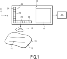
- a sample 10 to be imaged and an imaging device 12 are illustrated on figure 1 .
- the sample 10 is a biological sample.
- liquid tissue 14 is blood and such liquid tissue 14 is represented as two vessels 14.
- Each blood vessels 14 comprises diffusors.
- Acoustic contrast agents are specific examples of diffusors. For instance, gaseous bubbles may be considered.
- the imaging device is adapted to convert the information collected by ultrasound waves 18 into a map 20 of the sample 10.
- the imaging device 12 comprises an ultrasound imager 22 and a calculator 23.
- the ultrasound imager 22 is adapted to image a region of interest of the sample 10 as schematically illustrated in figure 2 .
- the ultrasound imager 22 comprises a first line of transducers 24 and a second line of transducers 26.
- Each line of transducers comprises a plurality of transducers 28.
- the first line 24 extends along a first direction named X in the remainder of the specification.
- the second line 26 extends along a second direction named Y in the remainder of the specification.
- the first direction X and the second direction Y are perpendicular.
- Such configuration of ultrasound imager 22 is usually called a row-column array of ultrasound transducers also named by the acronym RCA.
- the calculator 23 is adapted to carry out steps of a method for imaging.
- the method comprises an imaging step S50 which is iterated several times as illustrated by an arrow S52, a filtering step S54 and an estimating step S56.
- a set of N different observations of the sample 10 are acquired.
- Each imaging step S50 comprises several operations: an operation of emitting, an operation of collecting and an operation of image formation.
- unfocused ultrasound waves are emitted in a given region of interest of the sample 10.
- An unfocused ultrasound wave is a wave for which an aperture is defined.
- the aperture has a specific size labeled D.
- An ultrasound wave is considered as unfocused if the minimal width W min of the ultrasound beam associated to the ultrasound wave at a depth F is larger than the ratio of the product of the wavelength ⁇ of the ultrasound wave by the depth F with the specific size D of the aperture.
- W min > ⁇ ⁇ F D
- the location of interest is approximated by the intersection of the point spread functions of each observation.
- each point spread function comprise a blood area outside the location of interest A30 and a blood area in the location of interest A30.
- first point spread function PSF24 encompasses a first blood area A32
- second point spread function PSF26 encompasses a second blood area A34
- location of interest A30 encompasses a third blood area A36.
- the third blood area A36 is common to both point spread function PSF24 and PSF26.
- the unfocused ultrasound waves are emitted during a time interval and the ratio of the number of unfocused ultrasound waves over the time interval is superior or equal to 100 unfocused ultrasound waves per second.
- the frame rate corresponds to an emission with a pace superior or equal to 500 Hz.
- diffusors belonging to the given location of interest interacts with the emitted unfocused ultrasound waves. Notably, the diffusors emit retroreflected waves.
- Each observation associates to the location of interest a distinct signal according to the point spread function of said observation.
- the signal comprises a first contribution representative of the diffusors of blood inside the location of interest and a clutter contribution.
- the third contribution comes from blood outside of the location of interest.
- the integer M is superior or equal to 50.
- each temporal realization comprises a set of N different observations.
- the filter is a filter reducing the contribution coming from the solid tissue of the given location of interest in the observation.
- the filter is a filter removing the tissue signal.
- the filter is a singular value decomposition over the [M,P] space, where P represents the image space.
- the blood flow component is estimated for each location of the region of interest.
- the operation of applying consists in applying a statistical analysis on each observations of the set to discriminate the first contribution from the third contribution.
- the statistical analysis is a singular value decomposition.
- the statistical analysis is carried out over the [M,N] space to recover the blood flow signal common in the N observations.
- the statistical analysis comprises estimating the conjugated product between pairs of observations. This enables to realign the phase of the first contribution between pairs of observation and accumulate over the M temporal realizations.
- an estimate of the component of the blood flow signal is calculated based on the extracted contribution.
- the operation of calculating is carried out by evaluating the energy by summing the square of the recovered blood flow signal over the M temporal realizations.
- the method enables to eliminate, or at least reduce both the second contribution and the third contribution.
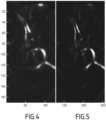
- the method enables to obtain better images as will now be illustrated in reference to figures 4 to 13 .
- figure 4 illustrates a map of a sample obtained by using a power Doppler imaging according to the prior art while figure 5 illustrates a map of a sample obtained by using the imaging device 12.
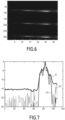
- figures 6 and 7 illustrate the results obtained by imaging the same object (comprising blood) which substantially corresponds to a line extending along a direction of extension.
- Curve C1 corresponds to the first method
- curve C2 corresponds to the second method
- curve C3 to the third method. It appears that the signal to noise ratio is greatly increased for the curves C2 and C3 compared to curve C1.
- Curve C4 corresponds to the first method
- curve C5 corresponds to the second method
- curve C6 corresponds to the third method. It appears that the signal to noise ratio is greatly increased for the curves C5 and C6 compared to curve C4.
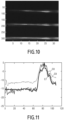
- figures 10 and 11 illustrate the results obtained by imaging the same object which substantially corresponds to a line extending along a direction of extension.
- the object is the same as for the second experiment.
- Curve C7 corresponds to the first method
- curve C8 corresponds to the fourth method
- curve C9 to the fifth method. It appears that the signal to noise ratio is greatly increased for the curves C7 and C9 compared to curve C8.
- Figure 12 illustrates the images obtained by three methods with from top to bottom on figure 12 the first method, the fourth method and the fifth method.
- the array of ultrasound transducers is a group of elements defining, physically or virtually, at least two linear or curvilinear subarrays whose elements spacing is inferior to four wavelengths at the emission central frequency along a unique preferential direction or curve.
Landscapes
- Health & Medical Sciences (AREA)
- Life Sciences & Earth Sciences (AREA)
- Engineering & Computer Science (AREA)
- Physics & Mathematics (AREA)
- Radar, Positioning & Navigation (AREA)
- Remote Sensing (AREA)
- Public Health (AREA)
- Molecular Biology (AREA)
- Veterinary Medicine (AREA)
- General Health & Medical Sciences (AREA)
- Biophysics (AREA)
- Nuclear Medicine, Radiotherapy & Molecular Imaging (AREA)
- Pathology (AREA)
- Radiology & Medical Imaging (AREA)
- Biomedical Technology (AREA)
- Heart & Thoracic Surgery (AREA)
- Medical Informatics (AREA)
- Animal Behavior & Ethology (AREA)
- Surgery (AREA)
- Acoustics & Sound (AREA)
- Computer Networks & Wireless Communication (AREA)
- General Physics & Mathematics (AREA)
- Vascular Medicine (AREA)
- Gynecology & Obstetrics (AREA)
- Hematology (AREA)
- Computer Vision & Pattern Recognition (AREA)
- Ultra Sonic Daignosis Equipment (AREA)
- Investigating Or Analysing Biological Materials (AREA)
Applications Claiming Priority (2)
| Application Number | Priority Date | Filing Date | Title |
|---|---|---|---|
| EP16306185 | 2016-09-16 | ||
| PCT/EP2017/073271 WO2018050817A1 (en) | 2016-09-16 | 2017-09-15 | Method for imaging a sample with blood and associated devices |
Publications (2)
| Publication Number | Publication Date |
|---|---|
| EP3512431A1 EP3512431A1 (en) | 2019-07-24 |
| EP3512431B1 true EP3512431B1 (en) | 2024-07-17 |
Family
ID=57189984
Family Applications (1)
| Application Number | Title | Priority Date | Filing Date |
|---|---|---|---|
| EP17771395.5A Active EP3512431B1 (en) | 2016-09-16 | 2017-09-15 | Method for imaging a sample with blood and associated devices |
Country Status (7)
| Country | Link |
|---|---|
| US (1) | US11617560B2 (enExample) |
| EP (1) | EP3512431B1 (enExample) |
| JP (1) | JP6912561B2 (enExample) |
| CN (1) | CN110072462B (enExample) |
| ES (1) | ES2988607T3 (enExample) |
| IL (1) | IL265223B2 (enExample) |
| WO (1) | WO2018050817A1 (enExample) |
Families Citing this family (3)
| Publication number | Priority date | Publication date | Assignee | Title |
|---|---|---|---|---|
| CN111281428B (zh) * | 2020-02-12 | 2021-08-06 | 深圳大学 | 一种用于监测血流动力学参数的超声探头 |
| KR102375825B1 (ko) * | 2021-04-28 | 2022-03-17 | 주식회사 엣지케어 | 초음파 영상장치 및 이를 포함하는 초음파 영상시스템 |
| CN113367675A (zh) * | 2021-05-21 | 2021-09-10 | 天津大学 | 基于激光散斑成像的血流动态检测方法、系统和介质 |
Family Cites Families (41)
| Publication number | Priority date | Publication date | Assignee | Title |
|---|---|---|---|---|
| JPH03176036A (ja) * | 1989-12-05 | 1991-07-31 | Aloka Co Ltd | 超音波ドプラ診断装置 |
| JPH03215250A (ja) * | 1990-01-19 | 1991-09-20 | Toshiba Corp | 超音波プローブ及び該超音波プローブを用いた超音波診断装置 |
| JPH03231650A (ja) * | 1990-02-07 | 1991-10-15 | Toshiba Corp | 超音波診断装置 |
| US5245587A (en) * | 1990-12-14 | 1993-09-14 | Hutson William H | Multi-dimensional signal processing and display |
| JPH10314171A (ja) * | 1997-05-15 | 1998-12-02 | Toshiba Iyou Syst Eng Kk | 超音波診断装置 |
| US6579238B1 (en) * | 2000-04-24 | 2003-06-17 | Acuson Corporation | Medical ultrasonic imaging system with adaptive multi-dimensional back-end mapping |
| US6318179B1 (en) * | 2000-06-20 | 2001-11-20 | Ge Medical Systems Global Technology Company, Llc | Ultrasound based quantitative motion measurement using speckle size estimation |
| US6468216B1 (en) * | 2000-08-24 | 2002-10-22 | Kininklijke Philips Electronics N.V. | Ultrasonic diagnostic imaging of the coronary arteries |
| ATE438109T1 (de) * | 2001-10-02 | 2009-08-15 | B K Medical As | Verfahren und vorrichtung zur geschwindigkeitsschätzung bei synthetischer aperturabbildung |
| KR20050055001A (ko) * | 2002-10-09 | 2005-06-10 | 마츠시타 덴끼 산교 가부시키가이샤 | 초음파 진단장치 |
| JP2004129797A (ja) * | 2002-10-09 | 2004-04-30 | Matsushita Electric Ind Co Ltd | 超音波診断装置 |
| JP4244300B2 (ja) * | 2003-03-24 | 2009-03-25 | 富士フイルム株式会社 | 超音波送受信装置 |
| TW200618774A (en) * | 2004-12-01 | 2006-06-16 | Yio-Wha Shau | Real time inspection system and inspection method for micro-circulation |
| US8162837B2 (en) * | 2005-06-13 | 2012-04-24 | Spentech, Inc. | Medical doppler ultrasound system for locating and tracking blood flow |
| US7720268B2 (en) * | 2005-07-15 | 2010-05-18 | Siemens Corporation | System and method for ultrasound specific segmentation using speckle distributions |
| US8626263B2 (en) * | 2006-04-13 | 2014-01-07 | General Electric Company | Methods and apparatus for relative perfusion and/or viability |
| US8306293B2 (en) * | 2008-05-15 | 2012-11-06 | University Of Virginia Patent Foundation | Reduction of echo decorrelation facilitating motion estimation |
| US10914826B2 (en) * | 2008-06-26 | 2021-02-09 | Verasonics, Inc. | High frame rate quantitative doppler flow imaging using unfocused transmit beams |
| US10172527B2 (en) * | 2009-07-31 | 2019-01-08 | Supersonic Imagine | Method and apparatus for measuring a physical parameter in mammal soft tissues by propagating shear waves |
| ITGE20090070A1 (it) * | 2009-08-31 | 2011-03-01 | Esaote Spa | Metodo e dispositivo per il rilevamento e la visualizzazione di informazioni emodinamiche in particolare del flusso ematico nelle vene, mediante ultrasoni |
| JP5499939B2 (ja) * | 2010-06-25 | 2014-05-21 | セイコーエプソン株式会社 | 測定装置、生体検査装置、流速測定方法、および圧力測定方法 |
| FR2969350B1 (fr) | 2010-12-16 | 2013-01-11 | Centre Nat Rech Scient | Procede et dispositif d'imagerie sonore. |
| CN103747742B (zh) * | 2011-04-14 | 2016-04-06 | 明尼苏达大学评议会 | 使用超声成像的脉管表征 |
| US9002080B2 (en) * | 2011-10-12 | 2015-04-07 | University Of Virginia Patent Foundation | Singular value filter for imaging or detection |
| JP2014023934A (ja) * | 2012-07-27 | 2014-02-06 | Samsung Electronics Co Ltd | 画像処理モジュール及び画像生成方法 |
| GB201216455D0 (en) * | 2012-09-14 | 2012-10-31 | Isis Innovation | Passive ultrasound imaging with sparse transducer arrays |
| WO2014138555A1 (en) * | 2013-03-07 | 2014-09-12 | Bernhard Sturm | Multimodal segmentation in intravascular images |
| WO2014192751A1 (ja) * | 2013-05-27 | 2014-12-04 | 株式会社東芝 | 画像処理装置及び画像処理方法 |
| WO2014193945A1 (en) | 2013-05-28 | 2014-12-04 | Duke University | Systems, methods and computer program products for doppler spatial coherence imaging |
| FR3008802B1 (fr) * | 2013-07-19 | 2015-08-14 | Centre Nat Rech Scient | Procede et dispositif de cartographie de milieux fibreux |
| KR20150118731A (ko) * | 2014-04-15 | 2015-10-23 | 삼성전자주식회사 | 초음파 영상 장치 및 그 제어 방법 |
| US10624612B2 (en) * | 2014-06-05 | 2020-04-21 | Chikayoshi Sumi | Beamforming method, measurement and imaging instruments, and communication instruments |
| JP6282942B2 (ja) * | 2014-06-18 | 2018-02-21 | キヤノンメディカルシステムズ株式会社 | 超音波診断装置、画像処理装置及び画像処理プログラム |
| EP2963672A1 (en) * | 2014-06-30 | 2016-01-06 | FEI Company | Computational scanning microscopy with improved resolution |
| FR3026493B1 (fr) | 2014-09-26 | 2021-02-12 | Centre Nat Rech Scient | Procede et dispositif d'imagerie acoustique. |
| US10548571B1 (en) * | 2014-11-21 | 2020-02-04 | Ultrasee Corp | Fast 2D blood flow velocity imaging |
| KR20160087221A (ko) * | 2015-01-13 | 2016-07-21 | 삼성메디슨 주식회사 | 초음파 진단 장치 및 그 동작방법 |
| US9855022B2 (en) * | 2015-01-19 | 2018-01-02 | B-K Medical Aps | 3-D flow estimation using row-column addressed transducer arrays |
| KR102573142B1 (ko) * | 2015-04-01 | 2023-08-31 | 베라소닉스, 인코포레이티드 | 임펄스 응답 추정 및 후향적 획득에 의한 코드화 여기 이미징을 위한 방법 및 시스템 |
| CN105726000B (zh) * | 2016-01-29 | 2019-03-22 | 北京工业大学 | 一种基于四肢血压脉搏的心脏血管功能参数的装置 |
| WO2017143456A1 (en) * | 2016-02-26 | 2017-08-31 | The University Of Western Ontario | Doppler measurement system and method |
-
2017
- 2017-09-15 EP EP17771395.5A patent/EP3512431B1/en active Active
- 2017-09-15 WO PCT/EP2017/073271 patent/WO2018050817A1/en not_active Ceased
- 2017-09-15 ES ES17771395T patent/ES2988607T3/es active Active
- 2017-09-15 CN CN201780057135.3A patent/CN110072462B/zh active Active
- 2017-09-15 US US16/330,948 patent/US11617560B2/en active Active
- 2017-09-15 JP JP2019514807A patent/JP6912561B2/ja active Active
-
2019
- 2019-03-07 IL IL265223A patent/IL265223B2/en unknown
Also Published As
| Publication number | Publication date |
|---|---|
| IL265223A (en) | 2019-05-30 |
| EP3512431A1 (en) | 2019-07-24 |
| US11617560B2 (en) | 2023-04-04 |
| JP2019528895A (ja) | 2019-10-17 |
| WO2018050817A1 (en) | 2018-03-22 |
| US20190247011A1 (en) | 2019-08-15 |
| JP6912561B2 (ja) | 2021-08-04 |
| IL265223B (en) | 2022-11-01 |
| CN110072462B (zh) | 2022-05-24 |
| ES2988607T3 (es) | 2024-11-21 |
| IL265223B2 (en) | 2023-03-01 |
| CN110072462A (zh) | 2019-07-30 |
Similar Documents
| Publication | Publication Date | Title |
|---|---|---|
| US12437363B2 (en) | Methods for high spatial and temporal resolution ultrasound imaging of microvessels | |
| US11589840B2 (en) | Methods for super-resolution ultrasound imaging of microvessels | |
| EP3548920B1 (en) | Methods and systems for filtering ultrasound image clutter | |
| Tiran et al. | Multiplane wave imaging increases signal-to-noise ratio in ultrafast ultrasound imaging | |
| US10338203B2 (en) | Classification preprocessing in medical ultrasound shear wave imaging | |
| EP3905960B1 (en) | Systems and methods for contrast enhanced imaging | |
| US12478352B2 (en) | Systems and methods for removing noise-induced bias in ultrasound blood flow imaging | |
| EP3512431B1 (en) | Method for imaging a sample with blood and associated devices | |
| WO2018099867A1 (en) | Methods and systems for filtering ultrasound image clutter | |
| US20160084948A1 (en) | Systems, methods and computer program products for doppler spatial coherence imaging | |
| Kou et al. | Fast high-resolution ultrasound microvessel imaging with null subtraction imaging-based beamforming | |
| US20240404066A1 (en) | System and method for segmenting an anatomical structure | |
| US12169928B2 (en) | Ultrasound imaging of vasculature | |
| Jafarzadeh et al. | Spatially segmented SVD clutter filtering in cardiac blood flow imaging with diverging waves | |
| CN118042989A (zh) | 用于分割解剖结构的系统和方法 | |
| HK40109430A (en) | Methods for super-resolution ultrasound imaging of microvessels | |
| Kerner et al. | Acoustic imaging using a maximum likelihood approach |
Legal Events
| Date | Code | Title | Description |
|---|---|---|---|
| STAA | Information on the status of an ep patent application or granted ep patent |
Free format text: STATUS: UNKNOWN |
|
| STAA | Information on the status of an ep patent application or granted ep patent |
Free format text: STATUS: THE INTERNATIONAL PUBLICATION HAS BEEN MADE |
|
| PUAI | Public reference made under article 153(3) epc to a published international application that has entered the european phase |
Free format text: ORIGINAL CODE: 0009012 |
|
| STAA | Information on the status of an ep patent application or granted ep patent |
Free format text: STATUS: REQUEST FOR EXAMINATION WAS MADE |
|
| 17P | Request for examination filed |
Effective date: 20190315 |
|
| AK | Designated contracting states |
Kind code of ref document: A1 Designated state(s): AL AT BE BG CH CY CZ DE DK EE ES FI FR GB GR HR HU IE IS IT LI LT LU LV MC MK MT NL NO PL PT RO RS SE SI SK SM TR |
|
| AX | Request for extension of the european patent |
Extension state: BA ME |
|
| DAV | Request for validation of the european patent (deleted) | ||
| DAX | Request for extension of the european patent (deleted) | ||
| RAP1 | Party data changed (applicant data changed or rights of an application transferred) |
Owner name: SORBONNE UNIVERSITE Owner name: UNIVERSITE DE PARIS Owner name: ECOLE SUPERIEURE DE PHYSIQUE ET DE CHIMIE INDUSTRIELLES DE LA VILLE DE PARIS Owner name: CENTRE NATIONAL DE LA RECHERCHE SCIENTIFIQUE Owner name: INSTITUT NATIONAL DE LA SANTE ET DE LA RECHERCHE MEDICALE (INSERM) |
|
| STAA | Information on the status of an ep patent application or granted ep patent |
Free format text: STATUS: EXAMINATION IS IN PROGRESS |
|
| 17Q | First examination report despatched |
Effective date: 20220405 |
|
| RAP3 | Party data changed (applicant data changed or rights of an application transferred) |
Owner name: SORBONNE UNIVERSITE Owner name: UNIVERSITE PARIS CITE Owner name: ECOLE SUPERIEURE DE PHYSIQUE ET DE CHIMIE INDUSTRIELLES DE LA VILLE DE PARIS Owner name: CENTRE NATIONAL DE LA RECHERCHE SCIENTIFIQUE Owner name: INSTITUT NATIONAL DE LA SANTE ET DE LA RECHERCHE MEDICALE (INSERM) |
|
| GRAP | Despatch of communication of intention to grant a patent |
Free format text: ORIGINAL CODE: EPIDOSNIGR1 |
|
| STAA | Information on the status of an ep patent application or granted ep patent |
Free format text: STATUS: GRANT OF PATENT IS INTENDED |
|
| INTG | Intention to grant announced |
Effective date: 20240220 |
|
| GRAS | Grant fee paid |
Free format text: ORIGINAL CODE: EPIDOSNIGR3 |
|
| GRAA | (expected) grant |
Free format text: ORIGINAL CODE: 0009210 |
|
| STAA | Information on the status of an ep patent application or granted ep patent |
Free format text: STATUS: THE PATENT HAS BEEN GRANTED |
|
| AK | Designated contracting states |
Kind code of ref document: B1 Designated state(s): AL AT BE BG CH CY CZ DE DK EE ES FI FR GB GR HR HU IE IS IT LI LT LU LV MC MK MT NL NO PL PT RO RS SE SI SK SM TR |
|
| P01 | Opt-out of the competence of the unified patent court (upc) registered |
Free format text: CASE NUMBER: APP_37959/2024 Effective date: 20240626 |
|
| REG | Reference to a national code |
Ref country code: CH Ref legal event code: EP |
|
| REG | Reference to a national code |
Ref country code: DE Ref legal event code: R096 Ref document number: 602017083366 Country of ref document: DE |
|
| REG | Reference to a national code |
Ref country code: IE Ref legal event code: FG4D |
|
| REG | Reference to a national code |
Ref country code: NL Ref legal event code: FP |
|
| REG | Reference to a national code |
Ref country code: LT Ref legal event code: MG9D |
|
| REG | Reference to a national code |
Ref country code: ES Ref legal event code: FG2A Ref document number: 2988607 Country of ref document: ES Kind code of ref document: T3 Effective date: 20241121 |
|
| PG25 | Lapsed in a contracting state [announced via postgrant information from national office to epo] |
Ref country code: PT Free format text: LAPSE BECAUSE OF FAILURE TO SUBMIT A TRANSLATION OF THE DESCRIPTION OR TO PAY THE FEE WITHIN THE PRESCRIBED TIME-LIMIT Effective date: 20241118 |
|
| REG | Reference to a national code |
Ref country code: AT Ref legal event code: MK05 Ref document number: 1703381 Country of ref document: AT Kind code of ref document: T Effective date: 20240717 |
|
| PG25 | Lapsed in a contracting state [announced via postgrant information from national office to epo] |
Ref country code: PT Free format text: LAPSE BECAUSE OF FAILURE TO SUBMIT A TRANSLATION OF THE DESCRIPTION OR TO PAY THE FEE WITHIN THE PRESCRIBED TIME-LIMIT Effective date: 20241118 |
|
| PG25 | Lapsed in a contracting state [announced via postgrant information from national office to epo] |
Ref country code: NO Free format text: LAPSE BECAUSE OF FAILURE TO SUBMIT A TRANSLATION OF THE DESCRIPTION OR TO PAY THE FEE WITHIN THE PRESCRIBED TIME-LIMIT Effective date: 20241017 |
|
| PG25 | Lapsed in a contracting state [announced via postgrant information from national office to epo] |
Ref country code: FI Free format text: LAPSE BECAUSE OF FAILURE TO SUBMIT A TRANSLATION OF THE DESCRIPTION OR TO PAY THE FEE WITHIN THE PRESCRIBED TIME-LIMIT Effective date: 20240717 Ref country code: GR Free format text: LAPSE BECAUSE OF FAILURE TO SUBMIT A TRANSLATION OF THE DESCRIPTION OR TO PAY THE FEE WITHIN THE PRESCRIBED TIME-LIMIT Effective date: 20241018 Ref country code: PL Free format text: LAPSE BECAUSE OF FAILURE TO SUBMIT A TRANSLATION OF THE DESCRIPTION OR TO PAY THE FEE WITHIN THE PRESCRIBED TIME-LIMIT Effective date: 20240717 |
|
| PG25 | Lapsed in a contracting state [announced via postgrant information from national office to epo] |
Ref country code: BG Free format text: LAPSE BECAUSE OF FAILURE TO SUBMIT A TRANSLATION OF THE DESCRIPTION OR TO PAY THE FEE WITHIN THE PRESCRIBED TIME-LIMIT Effective date: 20240717 |
|
| PG25 | Lapsed in a contracting state [announced via postgrant information from national office to epo] |
Ref country code: LV Free format text: LAPSE BECAUSE OF FAILURE TO SUBMIT A TRANSLATION OF THE DESCRIPTION OR TO PAY THE FEE WITHIN THE PRESCRIBED TIME-LIMIT Effective date: 20240717 |
|
| PG25 | Lapsed in a contracting state [announced via postgrant information from national office to epo] |
Ref country code: IS Free format text: LAPSE BECAUSE OF FAILURE TO SUBMIT A TRANSLATION OF THE DESCRIPTION OR TO PAY THE FEE WITHIN THE PRESCRIBED TIME-LIMIT Effective date: 20241117 Ref country code: AT Free format text: LAPSE BECAUSE OF FAILURE TO SUBMIT A TRANSLATION OF THE DESCRIPTION OR TO PAY THE FEE WITHIN THE PRESCRIBED TIME-LIMIT Effective date: 20240717 |
|
| PG25 | Lapsed in a contracting state [announced via postgrant information from national office to epo] |
Ref country code: HR Free format text: LAPSE BECAUSE OF FAILURE TO SUBMIT A TRANSLATION OF THE DESCRIPTION OR TO PAY THE FEE WITHIN THE PRESCRIBED TIME-LIMIT Effective date: 20240717 |
|
| PG25 | Lapsed in a contracting state [announced via postgrant information from national office to epo] |
Ref country code: RS Free format text: LAPSE BECAUSE OF FAILURE TO SUBMIT A TRANSLATION OF THE DESCRIPTION OR TO PAY THE FEE WITHIN THE PRESCRIBED TIME-LIMIT Effective date: 20241017 |
|
| PGFP | Annual fee paid to national office [announced via postgrant information from national office to epo] |
Ref country code: ES Payment date: 20241001 Year of fee payment: 8 |
|
| PG25 | Lapsed in a contracting state [announced via postgrant information from national office to epo] |
Ref country code: RS Free format text: LAPSE BECAUSE OF FAILURE TO SUBMIT A TRANSLATION OF THE DESCRIPTION OR TO PAY THE FEE WITHIN THE PRESCRIBED TIME-LIMIT Effective date: 20241017 Ref country code: PL Free format text: LAPSE BECAUSE OF FAILURE TO SUBMIT A TRANSLATION OF THE DESCRIPTION OR TO PAY THE FEE WITHIN THE PRESCRIBED TIME-LIMIT Effective date: 20240717 Ref country code: NO Free format text: LAPSE BECAUSE OF FAILURE TO SUBMIT A TRANSLATION OF THE DESCRIPTION OR TO PAY THE FEE WITHIN THE PRESCRIBED TIME-LIMIT Effective date: 20241017 Ref country code: LV Free format text: LAPSE BECAUSE OF FAILURE TO SUBMIT A TRANSLATION OF THE DESCRIPTION OR TO PAY THE FEE WITHIN THE PRESCRIBED TIME-LIMIT Effective date: 20240717 Ref country code: IS Free format text: LAPSE BECAUSE OF FAILURE TO SUBMIT A TRANSLATION OF THE DESCRIPTION OR TO PAY THE FEE WITHIN THE PRESCRIBED TIME-LIMIT Effective date: 20241117 Ref country code: HR Free format text: LAPSE BECAUSE OF FAILURE TO SUBMIT A TRANSLATION OF THE DESCRIPTION OR TO PAY THE FEE WITHIN THE PRESCRIBED TIME-LIMIT Effective date: 20240717 Ref country code: GR Free format text: LAPSE BECAUSE OF FAILURE TO SUBMIT A TRANSLATION OF THE DESCRIPTION OR TO PAY THE FEE WITHIN THE PRESCRIBED TIME-LIMIT Effective date: 20241018 Ref country code: FI Free format text: LAPSE BECAUSE OF FAILURE TO SUBMIT A TRANSLATION OF THE DESCRIPTION OR TO PAY THE FEE WITHIN THE PRESCRIBED TIME-LIMIT Effective date: 20240717 Ref country code: BG Free format text: LAPSE BECAUSE OF FAILURE TO SUBMIT A TRANSLATION OF THE DESCRIPTION OR TO PAY THE FEE WITHIN THE PRESCRIBED TIME-LIMIT Effective date: 20240717 Ref country code: AT Free format text: LAPSE BECAUSE OF FAILURE TO SUBMIT A TRANSLATION OF THE DESCRIPTION OR TO PAY THE FEE WITHIN THE PRESCRIBED TIME-LIMIT Effective date: 20240717 |
|
| PG25 | Lapsed in a contracting state [announced via postgrant information from national office to epo] |
Ref country code: SM Free format text: LAPSE BECAUSE OF FAILURE TO SUBMIT A TRANSLATION OF THE DESCRIPTION OR TO PAY THE FEE WITHIN THE PRESCRIBED TIME-LIMIT Effective date: 20240717 Ref country code: DK Free format text: LAPSE BECAUSE OF FAILURE TO SUBMIT A TRANSLATION OF THE DESCRIPTION OR TO PAY THE FEE WITHIN THE PRESCRIBED TIME-LIMIT Effective date: 20240717 Ref country code: RO Free format text: LAPSE BECAUSE OF FAILURE TO SUBMIT A TRANSLATION OF THE DESCRIPTION OR TO PAY THE FEE WITHIN THE PRESCRIBED TIME-LIMIT Effective date: 20240717 |
|
| REG | Reference to a national code |
Ref country code: DE Ref legal event code: R097 Ref document number: 602017083366 Country of ref document: DE |
|
| PG25 | Lapsed in a contracting state [announced via postgrant information from national office to epo] |
Ref country code: MC Free format text: LAPSE BECAUSE OF FAILURE TO SUBMIT A TRANSLATION OF THE DESCRIPTION OR TO PAY THE FEE WITHIN THE PRESCRIBED TIME-LIMIT Effective date: 20240717 Ref country code: EE Free format text: LAPSE BECAUSE OF FAILURE TO SUBMIT A TRANSLATION OF THE DESCRIPTION OR TO PAY THE FEE WITHIN THE PRESCRIBED TIME-LIMIT Effective date: 20240717 |
|
| PG25 | Lapsed in a contracting state [announced via postgrant information from national office to epo] |
Ref country code: CZ Free format text: LAPSE BECAUSE OF FAILURE TO SUBMIT A TRANSLATION OF THE DESCRIPTION OR TO PAY THE FEE WITHIN THE PRESCRIBED TIME-LIMIT Effective date: 20240717 |
|
| PG25 | Lapsed in a contracting state [announced via postgrant information from national office to epo] |
Ref country code: SK Free format text: LAPSE BECAUSE OF FAILURE TO SUBMIT A TRANSLATION OF THE DESCRIPTION OR TO PAY THE FEE WITHIN THE PRESCRIBED TIME-LIMIT Effective date: 20240717 |
|
| REG | Reference to a national code |
Ref country code: CH Ref legal event code: PL |
|
| PLBE | No opposition filed within time limit |
Free format text: ORIGINAL CODE: 0009261 |
|
| STAA | Information on the status of an ep patent application or granted ep patent |
Free format text: STATUS: NO OPPOSITION FILED WITHIN TIME LIMIT |
|
| 26N | No opposition filed |
Effective date: 20250422 |
|
| PG25 | Lapsed in a contracting state [announced via postgrant information from national office to epo] |
Ref country code: CH Free format text: LAPSE BECAUSE OF NON-PAYMENT OF DUE FEES Effective date: 20240930 |
|
| PG25 | Lapsed in a contracting state [announced via postgrant information from national office to epo] |
Ref country code: IE Free format text: LAPSE BECAUSE OF NON-PAYMENT OF DUE FEES Effective date: 20240915 |
|
| PG25 | Lapsed in a contracting state [announced via postgrant information from national office to epo] |
Ref country code: SE Free format text: LAPSE BECAUSE OF FAILURE TO SUBMIT A TRANSLATION OF THE DESCRIPTION OR TO PAY THE FEE WITHIN THE PRESCRIBED TIME-LIMIT Effective date: 20240717 |
|
| PGFP | Annual fee paid to national office [announced via postgrant information from national office to epo] |
Ref country code: LU Payment date: 20250820 Year of fee payment: 9 Ref country code: NL Payment date: 20250820 Year of fee payment: 9 |
|
| PGFP | Annual fee paid to national office [announced via postgrant information from national office to epo] |
Ref country code: DE Payment date: 20250820 Year of fee payment: 9 |
|
| PGFP | Annual fee paid to national office [announced via postgrant information from national office to epo] |
Ref country code: BE Payment date: 20250820 Year of fee payment: 9 Ref country code: GB Payment date: 20250820 Year of fee payment: 9 |
|
| PGFP | Annual fee paid to national office [announced via postgrant information from national office to epo] |
Ref country code: FR Payment date: 20250821 Year of fee payment: 9 |