EP3512344B1 - Food dough extrusion machine - Google Patents
Food dough extrusion machine Download PDFInfo
- Publication number
- EP3512344B1 EP3512344B1 EP17787869.1A EP17787869A EP3512344B1 EP 3512344 B1 EP3512344 B1 EP 3512344B1 EP 17787869 A EP17787869 A EP 17787869A EP 3512344 B1 EP3512344 B1 EP 3512344B1
- Authority
- EP
- European Patent Office
- Prior art keywords
- extrusion
- carrier
- extrusion unit
- guidance
- platform
- Prior art date
- Legal status (The legal status is an assumption and is not a legal conclusion. Google has not performed a legal analysis and makes no representation as to the accuracy of the status listed.)
- Active
Links
- 238000001125 extrusion Methods 0.000 title claims description 135
- 235000013305 food Nutrition 0.000 title claims description 26
- 239000000945 filler Substances 0.000 claims description 10
- 238000000034 method Methods 0.000 claims description 8
- 230000001681 protective effect Effects 0.000 claims description 3
- 238000000465 moulding Methods 0.000 description 4
- 238000004140 cleaning Methods 0.000 description 2
- -1 fillings Substances 0.000 description 2
- 239000000463 material Substances 0.000 description 2
- 238000003825 pressing Methods 0.000 description 2
- 241000209140 Triticum Species 0.000 description 1
- 235000021307 Triticum Nutrition 0.000 description 1
- 235000015173 baked goods and baking mixes Nutrition 0.000 description 1
- 235000015895 biscuits Nutrition 0.000 description 1
- 235000013339 cereals Nutrition 0.000 description 1
- 235000019219 chocolate Nutrition 0.000 description 1
- 235000014510 cooky Nutrition 0.000 description 1
- 235000012495 crackers Nutrition 0.000 description 1
- 239000006071 cream Substances 0.000 description 1
- 238000000151 deposition Methods 0.000 description 1
- 235000013601 eggs Nutrition 0.000 description 1
- 230000009969 flowable effect Effects 0.000 description 1
- 239000004615 ingredient Substances 0.000 description 1
- 239000008267 milk Substances 0.000 description 1
- 235000013336 milk Nutrition 0.000 description 1
- 210000004080 milk Anatomy 0.000 description 1
- 235000015145 nougat Nutrition 0.000 description 1
- 235000014571 nuts Nutrition 0.000 description 1
- 238000005086 pumping Methods 0.000 description 1
- 150000003839 salts Chemical class 0.000 description 1
- 235000002639 sodium chloride Nutrition 0.000 description 1
- 235000000346 sugar Nutrition 0.000 description 1
- 238000011144 upstream manufacturing Methods 0.000 description 1
Images


Classifications
-
- A—HUMAN NECESSITIES
- A21—BAKING; EDIBLE DOUGHS
- A21C—MACHINES OR EQUIPMENT FOR MAKING OR PROCESSING DOUGHS; HANDLING BAKED ARTICLES MADE FROM DOUGH
- A21C11/00—Other machines for forming the dough into its final shape before cooking or baking
- A21C11/16—Extruding machines
-
- A—HUMAN NECESSITIES
- A21—BAKING; EDIBLE DOUGHS
- A21C—MACHINES OR EQUIPMENT FOR MAKING OR PROCESSING DOUGHS; HANDLING BAKED ARTICLES MADE FROM DOUGH
- A21C3/00—Machines or apparatus for shaping batches of dough before subdivision
- A21C3/02—Dough-sheeters; Rolling-machines; Rolling-pins
-
- A—HUMAN NECESSITIES
- A21—BAKING; EDIBLE DOUGHS
- A21C—MACHINES OR EQUIPMENT FOR MAKING OR PROCESSING DOUGHS; HANDLING BAKED ARTICLES MADE FROM DOUGH
- A21C3/00—Machines or apparatus for shaping batches of dough before subdivision
- A21C3/02—Dough-sheeters; Rolling-machines; Rolling-pins
- A21C3/025—Dough-sheeters; Rolling-machines; Rolling-pins with one or more rollers moving perpendicularly to its rotation axis, e.g. reciprocally
-
- A—HUMAN NECESSITIES
- A21—BAKING; EDIBLE DOUGHS
- A21C—MACHINES OR EQUIPMENT FOR MAKING OR PROCESSING DOUGHS; HANDLING BAKED ARTICLES MADE FROM DOUGH
- A21C3/00—Machines or apparatus for shaping batches of dough before subdivision
- A21C3/04—Dough-extruding machines ; Hoppers with moving elements, e.g. rollers or belts as wall elements for drawing the dough
-
- A—HUMAN NECESSITIES
- A21—BAKING; EDIBLE DOUGHS
- A21C—MACHINES OR EQUIPMENT FOR MAKING OR PROCESSING DOUGHS; HANDLING BAKED ARTICLES MADE FROM DOUGH
- A21C9/00—Other apparatus for handling dough or dough pieces
- A21C9/08—Depositing, arranging and conveying apparatus for handling pieces, e.g. sheets of dough
-
- A—HUMAN NECESSITIES
- A21—BAKING; EDIBLE DOUGHS
- A21C—MACHINES OR EQUIPMENT FOR MAKING OR PROCESSING DOUGHS; HANDLING BAKED ARTICLES MADE FROM DOUGH
- A21C1/00—Mixing or kneading machines for the preparation of dough
- A21C1/08—Mixing or kneading machines for the preparation of dough with rollers
- A21C1/083—Mixing or kneading machines for the preparation of dough with rollers by calendering, i.e. working between rollers
-
- A—HUMAN NECESSITIES
- A21—BAKING; EDIBLE DOUGHS
- A21C—MACHINES OR EQUIPMENT FOR MAKING OR PROCESSING DOUGHS; HANDLING BAKED ARTICLES MADE FROM DOUGH
- A21C3/00—Machines or apparatus for shaping batches of dough before subdivision
- A21C3/02—Dough-sheeters; Rolling-machines; Rolling-pins
- A21C3/022—Laminating or undulating a continuous dough sheet, e.g. by folding transversely or longitudinally onto a moving surface
-
- A—HUMAN NECESSITIES
- A21—BAKING; EDIBLE DOUGHS
- A21C—MACHINES OR EQUIPMENT FOR MAKING OR PROCESSING DOUGHS; HANDLING BAKED ARTICLES MADE FROM DOUGH
- A21C3/00—Machines or apparatus for shaping batches of dough before subdivision
- A21C3/10—Machines or apparatus for shaping batches of dough before subdivision combined with dough-dividing apparatus
-
- A—HUMAN NECESSITIES
- A21—BAKING; EDIBLE DOUGHS
- A21C—MACHINES OR EQUIPMENT FOR MAKING OR PROCESSING DOUGHS; HANDLING BAKED ARTICLES MADE FROM DOUGH
- A21C5/00—Dough-dividing machines
- A21C5/003—Dough-dividing machines with revolving bodies, e.g. with bodies having spaces separated by radially oriented elements or walls
-
- A—HUMAN NECESSITIES
- A21—BAKING; EDIBLE DOUGHS
- A21D—TREATMENT, e.g. PRESERVATION, OF FLOUR OR DOUGH, e.g. BY ADDITION OF MATERIALS; BAKING; BAKERY PRODUCTS; PRESERVATION THEREOF
- A21D8/00—Methods for preparing or baking dough
- A21D8/02—Methods for preparing dough; Treating dough prior to baking
Definitions
- the invention relates to a food dough extrusion machine comprising a platform and at least one extrusion unit supported by the platform.
- the invention also relates to a method for changing the functionality of a dough extrusion machine.
- DE69923586T2 discloses a moulding device for moulding three-dimensional products from a mass of foodstuff.
- the moulding device comprises a mould having a mould cavity with a filling opening for filling the cavity with a portion of the mass.
- a closure means closes the filling opening of the mould cavity, so that the mass is held in the closed mould cavity for a fixing period after which the mould cavity is opened and the moulded product is removed.
- the moulding device may be a drum rotatable around a horizontal axis and comprising along its circumference a plurality of moulds.
- DE7118662U discloses a device for depositing dough on a carrier.
- the pressing action for pressing dough through outlet openings has to be provided by an operator by means of a lever system
- KR20130003951U2 , US5728411A , EP1602281A1 , WO96/23415A1 disclose dough extrusion machines according to the state of the art.
- Extrusion machines according to prior art are inflexible. The change of functionality, particularly the adaption to different food qualities is usually not possible or very difficult. Usually different extrusion machines are necessary in order to process different dough qualities.
- the dough extrusion machine shall allow for high flexibility or adjustability as well as for easily changing the functionality. Handling, exchange and cleaning of parts coming into contact with dough should be simplified. Furthermore, assembling and servicing shall be performed at lower costs and in shorter time.
- the invention facilitates adjustment, (re)moving and/or exchange of the extrusion unit.
- the guidance not only allows correct adjustment of the extrusion unit prior or during operation, but also allows to completely remove the extrusion unit by means of the guidance.
- the invention relates to a food dough extrusion machine, particularly for producing bakery products, such as biscuits, cookies, crackers, etc.
- the term "dough” has a broad meaning within the sense of the present application and comprises any flowable food masses or kneaded food material, including fillings, creams, paste-like material, and may contain cereals (particularly wheat), sugar, salt, milk, eggs, bakery improvers, chocolate, nougat, nuts and/or other ingredients.
- Platform may be any kind of support supporting the extrusion units, particularly a table, a frame, a base, etc., preferably with an integrated conveyor for transporting extruded dough.
- the extrusion unit has of course a plurality of outlet nozzles through which the dough flow (extruded dough) is discharged, e.g. onto a conveyor.
- the extrusion unit is supported on the platform by means of rolls which are rollable along the guidance. This reduces friction during movement.
- the rolls are mounted to the upper part of the extrusion unit.
- each roll is covered by a protective cover moving along with the respective roll.
- a protective cover moving along with the respective roll. In such a way the rolls are protected from dough, dirt and external impacts.
- the guidance is provided on the platform and the rolls are mounted to the extrusion unit.
- the guidance is stationary with respect to the platform.
- the guidance comprises at least two parallel rails, allowing a stable and well-defined support of the extrusion unit.
- the extrusion unit has a lower part and an upper part, wherein the lower part is detachable from the upper part, wherein the distance between the rails is larger than the width of the lower part. Width is the extension of the extrusion unit in a direction perpendicular to the rails.
- the lower part may be lowered through the area between the rails or rails of a corresponding carrier (see below).
- the lower part comprises a functional insert for conducting dough, preferably a pump and/or a filler block and/or a nozzle arrangement.
- a functional insert for conducting dough
- the functional insert may comprise structured rolls pumping the dough towards the outlet nozzles.
- a filler block is a passive element forming at least one, preferably a plurality channels for conducting dough from the feed rollers of the extrusion unit to the outlet nozzles.
- the extrusion unit comprises at least one feed roller, preferably (at least two) feed rollers, wherein preferably the at least one feed roller is accommodated in the upper part of the extrusion unit.
- the feed roller(s) is/are rotatably mounted within the extrusion unit and connected to a drive.
- the feed roller(s) force(s) dough from the dough supplying means (hopper) towards the outlet (nozzles).
- the upper part of the extrusion unit may further comprise a hopper or any other suitable dough supplying means. It is preferred that the upper part of the extrusion unit comprises two feeding rollers forming a gap for transferring the dough towards the outlet nozzles. Downstream of the feeding rollers and upstream of the outlet nozzles the lower part comprises a functional unit such as a pump housing (e.g. comprising structured rolls) or a filler block.
- a pump housing e.g. comprising structured rolls
- the extrusion unit has a guidance by which the dough supplying means is moveably supported, preferably by means of rolls which are rollable along the guidance, wherein preferably the guidance supporting the dough supplying means is essentially parallel to the guidance supporting the extrusion unit.
- the guidance supporting the dough supplying means is essentially parallel to the guidance supporting the extrusion unit.
- the lower part comprises a frame to which the functional insert is detachably mounted.
- the functional insert is detachably mounted.
- only the insert may be exchanged.
- the lower part is detachable from the upper part in a downward direction. This allows an ease removal of the lower part, particularly on an external carrier system. Particularly, the lower part may be lowered through an area between the rails of the guidance.
- the lower part is attached to the upper part by fastening means, preferably by screws, wherein the fastening means is accessible from the top or the side of the extrusion unit and/or comprises a quick release mechanism. This allows for good accessibility and simple removal of the lower part.
- the extrusion unit is detachably coupled to a drive unit for driving a functional insert in the lower part of the extrusion unit and/or feed rollers accommodated in the upper part of the extrusion unit.
- a drive unit for driving a functional insert in the lower part of the extrusion unit and/or feed rollers accommodated in the upper part of the extrusion unit.
- the driving unit may be stationary with respect to the guidance. This embodiment is preferred since the extrusion unit may be easily removed from the platform without the driving unit.
- the driving unit may comprise a drive for feed rollers accommodated in the upper part of the extrusion unit and a drive for the functional unit in the lower part of the extrusion unit, such as a pump.
- the platform comprises a conveyor (e.g. belt) for transporting dough extruded by the extrusion unit, wherein the guidance extends above the conveyor, preferably transverse, more preferred essentially perpendicular to the transporting direction of the conveyor.
- the guidance forms a bridge over the conveyor.
- the extrusion unit has longitudinal extension and extends transverse to the transporting direction of the conveyor.
- the outlet nozzles of the extrusion unit are arranged along the longitudinal direction of the extrusion unit.
- the dough extrusion machine comprises a carrier system for temporarily supporting an extrusion unit, wherein the carrier system comprises a first carrier having a guidance, preferably in form of two parallel rails, wherein the guidance may be brought into alignment with the guidance formed on the platform, such that the extrusion unit may be moved along the guidances from the platform to the first carrier and vice versa.
- the carrier system comprises a first carrier having a guidance, preferably in form of two parallel rails, wherein the guidance may be brought into alignment with the guidance formed on the platform, such that the extrusion unit may be moved along the guidances from the platform to the first carrier and vice versa.
- the extrusion unit may easily be transferred from the platform to the carrier system.
- the functionality of the extrusion unit may be changed, e.g. by exchanging the lower part of the extrusion unit.
- the carrier system comprises a second carrier that may be lowered with respect to the first carrier.
- the second carrier may be arranged below or within the first carrier for supporting and lowering the lower part of the extrusion unit, while the upper part is held by the first carrier.
- first carrier and/or the second carrier has/have rolls by which the first carrier and/or the second carrier are movable relative to the platform. This allows cleaning, servicing and/or changing functionality of the extrusion unit apart from the platform.
- the problem is also solved by a method for changing the functionality of a dough extrusion machine, according to claim 19.
- step (a) the extrusion unit is moved along the guidances from the platform to the first carrier of the carrier system and wherein step (b) is performed on the carrier system.
- the extrusion unit has a lower part and an upper part, wherein the lower part is detachable from the upper part, and wherein the carrier system comprises a second carrier that may be lowered with respect to the first carrier, and wherein the lower part of the carrier is lowered by the second carrier.
- the first carrier has two rails and wherein the lower part of the extrusion unit is lowered through the area between the rails of the first carrier.
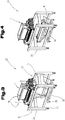
- Fig. 1 shows a food dough extrusion machine 10 comprising a platform 2 and an extrusion unit 1 supported by the platform 2.
- the extrusion machine 10 has a guidance 3 by which the at least one extrusion unit 10 is supported on the platform 2 and by which the at least one extrusion unit 10 is adjustable relative to the platform 2 and/or removable from the platform 2 ( Fig. 2 ).
- the extrusion unit 1 is supported on the platform 2 by means of rolls 6 which are rollable along the guidance 3 which comprises at least two parallel rails 4, 5.
- Each roll 6 may be covered by a protective cover moving along with the respective roll 6 ( Fig. 1 ).
- the platform 2 also comprises a conveyor 20 (in form of a transporting belt) for transporting dough extruded by the extrusion unit 1, wherein the guidance 3 extends above the conveyor 20, preferably transverse, more preferred essentially perpendicular to the transporting direction 21 of the conveyor 20.
- a conveyor 20 in form of a transporting belt
- the extrusion unit 1 has a lower part 8 for accommodating a functional insert 9 and an upper part 7 accommodating feed rollers 27 ( Figs. 8 and 9 ) for feeding dough from the hopper 11 to the functional insert 9.
- the functional insert 9 conducts dough towards outlet nozzles 18.
- the functional insert 9 may be a pump 16 e.g. in form of a pump housing ( Fig. 9 ) or a filler block 17 ( Fig. 8 ) and may also comprise the outlet nozzle arrangement 18. While the pump actively forces dough towards the outlet nozzles 18, the filler block 17 is a passive element e.g. comprising a plurality of channels leading towards the outlet nozzles 18. It depends on dough quality (weight, density, flow characteristic) which functional insert is best used.
- the extrusion unit of Fig. 8 has thus a different functionality than the extrusion unit of Fig. 9 .
- the extrusion unit 1 has a guidance by which the hopper 11 is moveably supported by means of rolls which are rollable along the guidance.
- the guidance supporting the hopper 11 is essentially parallel to the guidance 3 supporting the extrusion unit 1.
- the extrusion unit 1 is detachably coupled to a drive unit 12 for driving a functional insert 9 in the lower part 8 of the extrusion unit 1 and the feed rollers 27 accommodated in the upper part 7 of the extrusion unit 1.
- the drive unit 12 is mounted to the guidance 3.
- Fig. 2 shows a carrier system 22 for temporarily supporting an extrusion unit 1, wherein the carrier system 22 comprises a first carrier 23 having a guidance 13 in form of two parallel rails 14, 15, wherein the guidance 13 may be brought into alignment with the guidance 3 formed on the platform 2. In this alignment the extrusion unit 1 may be moved along the guidances 3, 13 from the platform 2 to the first carrier 23 and vice versa.
- Fig. 3 and 4 show that the carrier system 22 comprises also a second carrier 24 that may be lowered with respect to the first carrier 23.
- the second carrier 24 With the second carrier 24 the lower part 8 of the extrusion unit 1 may be lowered and removed/exchanged ( Fig. 4 ).
- the second carrier 24 has a scissor-type lowering mechanism.
- the lower part 8 of the extrusion unit 1 is detachable from the upper part 7 (by removing screws 28 in Fig. 3 ), wherein the distance between the rails 4, 5 and 14, 15 is larger than the width of the lower part 8, such that the lower part 8 may be lowered through the area between the rails 14, 15.
- the first carrier 23 and the second carrier 24 have rolls 25, 26 by which they are movable relative to the platform 2.
- the lower part 8 comprises a frame 19 to which the functional insert 9 is detachably mounted ( Fig. 5, 6 and 7 ).
- a filler block 17 with a nozzle arrangement 18 is inserted in the frame 19.
- a pump 16 (housing) with a nozzle arrangement 18 is inserted in the frame 19.
- the lower part 8 is removed and exchanged as a whole or only the functional insert 9 is exchanged and the same frame 19 is used again.
- the lower part 8 is detachable from the upper part 7 in a downward direction.
- the method for changing the functionality of a dough extrusion machine 10 comprises the steps of: (a) removing the extrusion unit 1 from the platform 2 (see Fig. 2 ) and (b) exchanging a functional insert 9 of the extrusion unit 1 ( Fig. 3 and 4 ) and (c) moving the extrusion unit 1 with the exchanged functional insert 9 to the platform 2.
- Removing or exchanging the functional insert 9 is done by means of the carrier system 22.
- the first carrier 23 supports the upper part 7 of the extrusion unit 1, while the second carrier 24 supports the lower part 8 and is lowered with respect to the first carrier 23.
- the second carrier 24 may be - independently of the first carrier 23 - moved to a different place and a new/different lower part or only a new/different functional insert may be arranged to the second carrier 24 in order to be joined with the upper part (waiting on the first carrier 23) again.
Description
- The invention relates to a food dough extrusion machine comprising a platform and at least one extrusion unit supported by the platform. The invention also relates to a method for changing the functionality of a dough extrusion machine.
-
DE69923586T2 discloses a moulding device for moulding three-dimensional products from a mass of foodstuff. The moulding device comprises a mould having a mould cavity with a filling opening for filling the cavity with a portion of the mass. A closure means closes the filling opening of the mould cavity, so that the mass is held in the closed mould cavity for a fixing period after which the mould cavity is opened and the moulded product is removed. The moulding device may be a drum rotatable around a horizontal axis and comprising along its circumference a plurality of moulds. -
DE7118662U discloses a device for depositing dough on a carrier. The pressing action for pressing dough through outlet openings has to be provided by an operator by means of a lever system -
KR20130003951U2 US5728411A ,EP1602281A1 ,WO96/23415A1 - Extrusion machines according to prior art are inflexible. The change of functionality, particularly the adaption to different food qualities is usually not possible or very difficult. Usually different extrusion machines are necessary in order to process different dough qualities.
- Accordingly, it is an object of the invention to provide an improved dough extrusion machine for food industry. In particular, the dough extrusion machine shall allow for high flexibility or adjustability as well as for easily changing the functionality. Handling, exchange and cleaning of parts coming into contact with dough should be simplified. Furthermore, assembling and servicing shall be performed at lower costs and in shorter time.
- The problem of the invention is solved by a dough extrusion machine according to claim 1.
- The invention facilitates adjustment, (re)moving and/or exchange of the extrusion unit. The guidance not only allows correct adjustment of the extrusion unit prior or during operation, but also allows to completely remove the extrusion unit by means of the guidance.
- The invention relates to a food dough extrusion machine, particularly for producing bakery products, such as biscuits, cookies, crackers, etc. The term "dough" has a broad meaning within the sense of the present application and comprises any flowable food masses or kneaded food material, including fillings, creams, paste-like material, and may contain cereals (particularly wheat), sugar, salt, milk, eggs, bakery improvers, chocolate, nougat, nuts and/or other ingredients.
- Platform may be any kind of support supporting the extrusion units, particularly a table, a frame, a base, etc., preferably with an integrated conveyor for transporting extruded dough.
- The extrusion unit has of course a plurality of outlet nozzles through which the dough flow (extruded dough) is discharged, e.g. onto a conveyor.
- In a preferred embodiment the extrusion unit is supported on the platform by means of rolls which are rollable along the guidance. This reduces friction during movement. Preferably, the rolls are mounted to the upper part of the extrusion unit.
- Preferably, each roll is covered by a protective cover moving along with the respective roll. In such a way the rolls are protected from dough, dirt and external impacts.
- In a preferred embodiment the guidance is provided on the platform and the rolls are mounted to the extrusion unit. Here, the guidance is stationary with respect to the platform.
- According to the invention the guidance comprises at least two parallel rails, allowing a stable and well-defined support of the extrusion unit.
- According to the invention the extrusion unit has a lower part and an upper part, wherein the lower part is detachable from the upper part, wherein the distance between the rails is larger than the width of the lower part. Width is the extension of the extrusion unit in a direction perpendicular to the rails. Here, the lower part may be lowered through the area between the rails or rails of a corresponding carrier (see below).
- In a preferred embodiment the lower part comprises a functional insert for conducting dough, preferably a pump and/or a filler block and/or a nozzle arrangement. By exchanging only the lower part or only the functional insert (the upper part stay the same) the functionality of the extrusion machine may be changed in an quick and elegant way. In the case of a pump the functional insert may comprise structured rolls pumping the dough towards the outlet nozzles. A filler block is a passive element forming at least one, preferably a plurality channels for conducting dough from the feed rollers of the extrusion unit to the outlet nozzles.
- Preferably, the extrusion unit comprises at least one feed roller, preferably (at least two) feed rollers, wherein preferably the at least one feed roller is accommodated in the upper part of the extrusion unit. The feed roller(s) is/are rotatably mounted within the extrusion unit and connected to a drive. The feed roller(s) force(s) dough from the dough supplying means (hopper) towards the outlet (nozzles).
- The upper part of the extrusion unit may further comprise a hopper or any other suitable dough supplying means. It is preferred that the upper part of the extrusion unit comprises two feeding rollers forming a gap for transferring the dough towards the outlet nozzles. Downstream of the feeding rollers and upstream of the outlet nozzles the lower part comprises a functional unit such as a pump housing (e.g. comprising structured rolls) or a filler block.
- Preferably, the extrusion unit has a guidance by which the dough supplying means is moveably supported, preferably by means of rolls which are rollable along the guidance, wherein preferably the guidance supporting the dough supplying means is essentially parallel to the guidance supporting the extrusion unit. This allows adjustment of the dough supplying means (hopper) prior or during operation.
- In a preferred embodiment the lower part comprises a frame to which the functional insert is detachably mounted. Here, only the insert may be exchanged.
- Preferably, the lower part is detachable from the upper part in a downward direction. This allows an ease removal of the lower part, particularly on an external carrier system. Particularly, the lower part may be lowered through an area between the rails of the guidance.
- Preferably, the lower part is attached to the upper part by fastening means, preferably by screws, wherein the fastening means is accessible from the top or the side of the extrusion unit and/or comprises a quick release mechanism. This allows for good accessibility and simple removal of the lower part.
- In a preferred embodiment the extrusion unit is detachably coupled to a drive unit for driving a functional insert in the lower part of the extrusion unit and/or feed rollers accommodated in the upper part of the extrusion unit. By moving the extrusion unit along the guidance it may be removed from the driving unit. The driving unit may be stationary with respect to the guidance. This embodiment is preferred since the extrusion unit may be easily removed from the platform without the driving unit. The driving unit may comprise a drive for feed rollers accommodated in the upper part of the extrusion unit and a drive for the functional unit in the lower part of the extrusion unit, such as a pump.
- In a preferred embodiment the platform comprises a conveyor (e.g. belt) for transporting dough extruded by the extrusion unit, wherein the guidance extends above the conveyor, preferably transverse, more preferred essentially perpendicular to the transporting direction of the conveyor. Here, the guidance forms a bridge over the conveyor. It is preferred that the extrusion unit has longitudinal extension and extends transverse to the transporting direction of the conveyor. The outlet nozzles of the extrusion unit are arranged along the longitudinal direction of the extrusion unit.
- In a preferred embodiment the dough extrusion machine comprises a carrier system for temporarily supporting an extrusion unit, wherein the carrier system comprises a first carrier having a guidance, preferably in form of two parallel rails, wherein the guidance may be brought into alignment with the guidance formed on the platform, such that the extrusion unit may be moved along the guidances from the platform to the first carrier and vice versa. By aligning the guidance of the platform and the guidance of the first carrier the extrusion unit may easily be transferred from the platform to the carrier system. On the carrier system the functionality of the extrusion unit may be changed, e.g. by exchanging the lower part of the extrusion unit.
- In a preferred embodiment the carrier system comprises a second carrier that may be lowered with respect to the first carrier. The second carrier may be arranged below or within the first carrier for supporting and lowering the lower part of the extrusion unit, while the upper part is held by the first carrier.
- In a preferred embodiment the first carrier and/or the second carrier has/have rolls by which the first carrier and/or the second carrier are movable relative to the platform. This allows cleaning, servicing and/or changing functionality of the extrusion unit apart from the platform.
- The problem is also solved by a method for changing the functionality of a dough extrusion machine, according to
claim 19. - In a preferred embodiment during step (a) the extrusion unit is moved along the guidances from the platform to the first carrier of the carrier system and wherein step (b) is performed on the carrier system.
- In a preferred embodiment the extrusion unit has a lower part and an upper part, wherein the lower part is detachable from the upper part, and wherein the carrier system comprises a second carrier that may be lowered with respect to the first carrier, and wherein the lower part of the carrier is lowered by the second carrier.
- In a preferred embodiment the first carrier has two rails and wherein the lower part of the extrusion unit is lowered through the area between the rails of the first carrier.
- For a better understanding of the invention the latter is explained in more detail with reference to the following Figures.
-
Fig. 1 shows a dough extrusion machine according to the invention, -
Fig. 2 shows the dough extrusion machine with a carrier system, -
Fig. 3 shows the carrier system comprising a first carrier and a second carrier, -
Fig. 4 shows the carrier system with lowered second carrier, -
Fig. 5 shows the frame of the lower part of the extrusion unit, -
Fig. 6 shows the frame with a filler block, -
Fig. 7 shows the frame with a pump housing, -
Fig. 8 shows in a cross sectional view the extrusion unit having a filler block, -
Fig. 9 shows in a cross sectional view the extrusion unit having a pump. - Generally, the same parts or similar parts are denoted with the same/similar names and reference signs. The features disclosed in the description apply to parts with the same/similar names respectively reference signs. Indicating the orientation and relative position (up, down, sideward, etc.) is related to the associated Figure, and indication of the orientation and/or relative position has to be amended in different Figures accordingly as the case may be.
-
Fig. 1 shows a fooddough extrusion machine 10 comprising aplatform 2 and an extrusion unit 1 supported by theplatform 2. Theextrusion machine 10 has a guidance 3 by which the at least oneextrusion unit 10 is supported on theplatform 2 and by which the at least oneextrusion unit 10 is adjustable relative to theplatform 2 and/or removable from the platform 2 (Fig. 2 ). - The extrusion unit 1 is supported on the
platform 2 by means ofrolls 6 which are rollable along the guidance 3 which comprises at least twoparallel rails roll 6 may be covered by a protective cover moving along with the respective roll 6 (Fig. 1 ). - The
platform 2 also comprises a conveyor 20 (in form of a transporting belt) for transporting dough extruded by the extrusion unit 1, wherein the guidance 3 extends above theconveyor 20, preferably transverse, more preferred essentially perpendicular to the transportingdirection 21 of theconveyor 20. - The extrusion unit 1 has a
lower part 8 for accommodating a functional insert 9 and anupper part 7 accommodating feed rollers 27 (Figs. 8 and9 ) for feeding dough from thehopper 11 to the functional insert 9. The functional insert 9 conducts dough towardsoutlet nozzles 18. The functional insert 9 may be apump 16 e.g. in form of a pump housing (Fig. 9 ) or a filler block 17 (Fig. 8 ) and may also comprise theoutlet nozzle arrangement 18. While the pump actively forces dough towards the outlet nozzles 18, thefiller block 17 is a passive element e.g. comprising a plurality of channels leading towards theoutlet nozzles 18. It depends on dough quality (weight, density, flow characteristic) which functional insert is best used. The extrusion unit ofFig. 8 has thus a different functionality than the extrusion unit ofFig. 9 . - As can be seen from
Fig. 1 the extrusion unit 1 has a guidance by which thehopper 11 is moveably supported by means of rolls which are rollable along the guidance. The guidance supporting thehopper 11 is essentially parallel to the guidance 3 supporting the extrusion unit 1. - As can be seen from
Fig. 2 the extrusion unit 1 is detachably coupled to adrive unit 12 for driving a functional insert 9 in thelower part 8 of the extrusion unit 1 and thefeed rollers 27 accommodated in theupper part 7 of the extrusion unit 1. Here, thedrive unit 12 is mounted to the guidance 3. -
Fig. 2 shows acarrier system 22 for temporarily supporting an extrusion unit 1, wherein thecarrier system 22 comprises afirst carrier 23 having aguidance 13 in form of twoparallel rails guidance 13 may be brought into alignment with the guidance 3 formed on theplatform 2. In this alignment the extrusion unit 1 may be moved along theguidances 3, 13 from theplatform 2 to thefirst carrier 23 and vice versa. -
Fig. 3 and 4 show that thecarrier system 22 comprises also asecond carrier 24 that may be lowered with respect to thefirst carrier 23. With thesecond carrier 24 thelower part 8 of the extrusion unit 1 may be lowered and removed/exchanged (Fig. 4 ). Thesecond carrier 24 has a scissor-type lowering mechanism. Thelower part 8 of the extrusion unit 1 is detachable from the upper part 7 (by removingscrews 28 inFig. 3 ), wherein the distance between therails lower part 8, such that thelower part 8 may be lowered through the area between therails - The
first carrier 23 and thesecond carrier 24 haverolls platform 2. - The
lower part 8 comprises aframe 19 to which the functional insert 9 is detachably mounted (Fig. 5, 6 and 7 ). InFig. 6 afiller block 17 with anozzle arrangement 18 is inserted in theframe 19. InFig. 7 a pump 16 (housing) with anozzle arrangement 18 is inserted in theframe 19. In order to change the functionality of the extrusion unit 1, thelower part 8 is removed and exchanged as a whole or only the functional insert 9 is exchanged and thesame frame 19 is used again. - As can be seen from
Fig. 3 and 4 thelower part 8 is detachable from theupper part 7 in a downward direction. - The method for changing the functionality of a
dough extrusion machine 10 comprises the steps of: (a) removing the extrusion unit 1 from the platform 2 (seeFig. 2 ) and (b) exchanging a functional insert 9 of the extrusion unit 1 (Fig. 3 and 4 ) and (c) moving the extrusion unit 1 with the exchanged functional insert 9 to theplatform 2. - Removing or exchanging the functional insert 9 is done by means of the
carrier system 22. Thefirst carrier 23 supports theupper part 7 of the extrusion unit 1, while thesecond carrier 24 supports thelower part 8 and is lowered with respect to thefirst carrier 23. Thesecond carrier 24 may be - independently of the first carrier 23 - moved to a different place and a new/different lower part or only a new/different functional insert may be arranged to thesecond carrier 24 in order to be joined with the upper part (waiting on the first carrier 23) again. - In the step shown in
Fig. 3 and 4 thelower part 8 of the extrusion unit 1 is lowered through the area between therails -
- 1
- extrusion unit
- 2
- platform
- 3
- guidance
- 4
- rail
- 5
- rail
- 6
- rolls
- 7
- upper part
- 8
- lower part
- 9
- functional insert
- 10
- frame
- 11
- hopper
- 12
- drive unit
- 13
- guidance
- 14
- rail
- 15
- rail
- 16
- pump
- 17
- filler block
- 18
- nozzle arrangement
- 19
- frame
- 20
- conveyor
- 21
- transporting direction
- 22
- carrier system
- 23
- first carrier
- 24
- second carrier
- 25
- rolls
- 26
- rolls
- 27
- feed roller
- 28
- screws
Claims (22)
- Food dough extrusion machine (10) comprising- a platform (2) and- at least one extrusion unit (1) supported by the platform (2),wherein the extrusion machine (10) has a guidance (3) by which the at least one extrusion unit (10) is supported on the platform (2) and by which the at least one extrusion unit (10) is adjustable relative to the platform (2) and removable from the platform (2), wherein the guidance (3) comprises at least two parallel rails (4, 5), characterized in that the extrusion unit (1) has a lower part (8) and an upper part (7), wherein the lower part (8) is detachable from the upper part (7), and wherein the distance between the rails is larger than the width of the lower part.
- Food dough extrusion machine according to claim 1, wherein the extrusion unit (1) is supported on the platform (2) by means of rolls (6) which are rollable along the guidance (3), wherein preferably each roll (6) is covered by a protective cover moving along with the respective roll (6).
- Food dough extrusion machine according to claim 1 or 2, wherein the guidance (3) is provided on the platform (2) and the rolls (6) are mounted to the extrusion unit (1).
- Food dough extrusion machine according to one of the preceding claims, wherein the distance between the rails (4, 5) is larger than the width of the lower part (8).
- Food dough extrusion machine according to one of the preceding claims, wherein the lower part (8) comprises a functional insert (9) for conducting dough, wherein preferably the functional insert comprises a pump (16) and/or a filler block (17) and/or a nozzle arrangement (18).
- Food dough extrusion machine according to claim 5, wherein the lower part (8) comprises a frame (19) to which the functional insert (9) is detachably mounted.
- Food dough extrusion machine according to one of the preceding claims, wherein the lower part (8) is detachable from the upper part (7) in a downward direction.
- Food dough extrusion machine according to one of the preceding claims, wherein the lower part (8) is attached to the upper part (7) by fastening means, preferably by screws (28), wherein the fastening means is accessible from the top or the side of the extrusion unit (1) and/or comprises a quick release mechanism.
- Food dough extrusion machine according to one of the preceding claims, wherein the upper part (7) has rolls (6) which are rollable along the guidance (3).
- Food dough extrusion machine according to one of the preceding claims, wherein the extrusion unit (1) is detachably coupled to a drive unit (12) for driving a functional insert (9) in the lower part (8) of the extrusion unit (1) and/or feed rollers (27) accommodated in the upper part (7) of the extrusion unit (1), wherein preferably the drive unit (12) is mounted to the guidance (3) and/or wherein preferably the drive unit (12) is stationary with respect to the guidance (3).
- Food dough extrusion machine according to one of the preceding claims, wherein the platform (2) comprises a conveyor (20) for transporting dough extruded by the extrusion unit (1), wherein the guidance (3) extends above the conveyor (20), preferably transverse, more preferred essentially perpendicular to the transporting direction (21) of the conveyor (20).
- Food dough extrusion machine according to one of the preceding claims, wherein the extrusion unit (1) has a plurality of outlet nozzles through which the dough flow is dischargeable, preferably onto a conveyor (20).
- Food dough extrusion machine according to one of the preceding claims, wherein the extrusion unit (1) comprises at least one feed roller (27), preferably feed rollers (27), wherein preferably the at least one feed roller (27) is accommodated in the upper part (7) of the extrusion unit (1).
- Food dough extrusion machine according to one of the preceding claims, wherein the extrusion unit (1), preferably the upper part (7) of the extrusion unit (1), comprises dough supplying means, preferably a hopper (11).
- Food dough extrusion machine according to claim 14, wherein the extrusion unit (1) has a guidance by which the dough supplying means is moveably supported, preferably by means of rolls which are rollable along the guidance, wherein preferably the guidance supporting the dough supplying means is essentially parallel to the guidance (3) supporting the extrusion unit (1).
- Food dough extrusion machine according to one of the preceding claims, wherein the dough extrusion machine (10) comprises a carrier system (22) for temporarily supporting an extrusion unit (1), wherein the carrier system (22) comprises a first carrier (23) having a guidance (13), preferably in form of two parallel rails (14, 15), wherein the guidance (13) may be brought into alignment with the guidance (3) formed on the platform (2), such that the extrusion unit (1) may be moved along the guidances (3, 13) from the platform (2) to the first carrier (23) and vice versa.
- Food dough extrusion machine according to claim 16, wherein the carrier system (22) comprises a second carrier (24) that may be lowered with respect to the first carrier (23), wherein preferably the second carrier (24) has a scissor-type lowering mechanism.
- Food dough extrusion machine according to claim 16 or 17, wherein the first carrier (23) and/or the second carrier (24) has/have rolls (25, 26) by which the first carrier (23) and/or the second carrier (24) are movable relative to the platform (2).
- Method for changing the functionality of a dough extrusion machine according to one of the preceding claims, comprising the steps of: (a) removing the extrusion unit (1) from the platform (2) and (b) exchanging a functional insert (9) of the extrusion unit (1) and (c) moving the extrusion unit (1) to the platform (2).
- Method according to claim 19, wherein the extrusion machine is formed according to one of the claims 18 to 20 and wherein during step (a) the extrusion unit (1) is moved along the guidances (3, 13) from the platform (2) to the first carrier (23) of the carrier system (22) and wherein step (b) is performed on the carrier system (22).
- Method according to claim 20, wherein the extrusion unit (1) has a lower part (8) and an upper part (7), wherein the lower part (8) is detachable from the upper part (7), and wherein the carrier system (22) comprises a second carrier (24) that may be lowered with respect to the first carrier (23), and wherein the lower part (8) is lowered by the second carrier (24).
- Method according to claim 20 or 21, wherein the first carrier (23) has two rails (14, 15) and wherein the lower part (8) of the extrusion unit (1) is lowered through the area between the rails (14, 15).
Priority Applications (4)
| Application Number | Priority Date | Filing Date | Title |
|---|---|---|---|
| EP21153971.3A EP3834617A1 (en) | 2016-09-16 | 2017-09-14 | Food dough extrusion machine |
| PL17787869T PL3512344T3 (en) | 2016-09-16 | 2017-09-14 | Food dough extrusion machine |
| RS20210604A RS61850B1 (en) | 2016-09-16 | 2017-09-14 | Food dough extrusion machine |
| HRP20210752TT HRP20210752T1 (en) | 2016-09-16 | 2021-05-12 | Food dough extrusion machine |
Applications Claiming Priority (2)
| Application Number | Priority Date | Filing Date | Title |
|---|---|---|---|
| DE102016011124 | 2016-09-16 | ||
| PCT/AT2017/060232 WO2018049457A1 (en) | 2016-09-16 | 2017-09-14 | Food dough extrusion machine |
Related Child Applications (1)
| Application Number | Title | Priority Date | Filing Date |
|---|---|---|---|
| EP21153971.3A Division EP3834617A1 (en) | 2016-09-16 | 2017-09-14 | Food dough extrusion machine |
Publications (2)
| Publication Number | Publication Date |
|---|---|
| EP3512344A1 EP3512344A1 (en) | 2019-07-24 |
| EP3512344B1 true EP3512344B1 (en) | 2021-02-24 |
Family
ID=60161898
Family Applications (2)
| Application Number | Title | Priority Date | Filing Date |
|---|---|---|---|
| EP17787869.1A Active EP3512344B1 (en) | 2016-09-16 | 2017-09-14 | Food dough extrusion machine |
| EP21153971.3A Withdrawn EP3834617A1 (en) | 2016-09-16 | 2017-09-14 | Food dough extrusion machine |
Family Applications After (1)
| Application Number | Title | Priority Date | Filing Date |
|---|---|---|---|
| EP21153971.3A Withdrawn EP3834617A1 (en) | 2016-09-16 | 2017-09-14 | Food dough extrusion machine |
Country Status (11)
| Country | Link |
|---|---|
| US (1) | US11006636B2 (en) |
| EP (2) | EP3512344B1 (en) |
| CN (1) | CN109890211B (en) |
| BR (1) | BR112019003972B1 (en) |
| DK (1) | DK3512344T3 (en) |
| ES (1) | ES2870129T3 (en) |
| HR (1) | HRP20210752T1 (en) |
| PL (1) | PL3512344T3 (en) |
| RS (1) | RS61850B1 (en) |
| RU (1) | RU2720918C1 (en) |
| WO (1) | WO2018049457A1 (en) |
Families Citing this family (4)
| Publication number | Priority date | Publication date | Assignee | Title |
|---|---|---|---|---|
| CN111685354B (en) * | 2020-05-15 | 2021-10-08 | 台州市宝刚机械有限公司 | Material extruder and application thereof |
| EP4209128A1 (en) | 2022-01-05 | 2023-07-12 | Gea Comas S.P.A. | Metering machine for metering and/or injecting food products |
| EP4209129A1 (en) | 2022-01-05 | 2023-07-12 | Gea Comas S.P.A. | Metering machine for metering and/or injecting food products |
| DE102022209174A1 (en) * | 2022-09-02 | 2024-03-07 | Werner & Pfleiderer Industrielle Backtechnik Gmbh | Device for producing a continuous strip of dough and dough portions in the form of sections of the dough strip |
Citations (11)
| Publication number | Priority date | Publication date | Assignee | Title |
|---|---|---|---|---|
| US3782428A (en) | 1970-08-22 | 1974-01-01 | Ayers J And Co Ltd | Food dispensing apparatus |
| IT1234903B (en) | 1988-03-10 | 1992-06-02 | P M B Di Ing Antonio Polin & C | Moulding and collating machine for the dessert industry, in particular for the formation of multiple mixture biscotti |
| IT1234902B (en) | 1988-03-10 | 1992-06-02 | P M B Di Ing Antonio Polin & C | Moulding and collating machine for the dessert industry, in particular for the formation of biscotti |
| JPH0646734A (en) * | 1992-07-31 | 1994-02-22 | Sanyo Electric Co Ltd | Apparatus for cutting noodle strip of automatic noodle making machine |
| US5728411A (en) * | 1995-11-20 | 1998-03-17 | Exact Mixing Systems, Inc. | Mixing system for dispensing measured volumes of kneadable material |
| US6139178A (en) | 1996-03-14 | 2000-10-31 | Apv Baker Division Of Apv Baker North America, Inc. | Movably mounted feed-roll head for extruders |
| ITVR990076A1 (en) | 1999-09-17 | 2001-03-17 | Polin & C Spa Ing | EXTRUSION GROUP FOR CASTING MACHINE, IN PARTICULAR FOR THE PRODUCTION OF SWEET PRODUCTS. |
| US20030185952A1 (en) | 2002-03-27 | 2003-10-02 | Demars Jimmy A. | Apparatus and method for processing viscous food products |
| WO2010040504A2 (en) | 2008-10-06 | 2010-04-15 | Franz Haas Waffel- Und Keksanlagen-Industrie Gmbh | Food manufacturing apparatus and related method |
| KR20130003951U (en) * | 2011-12-22 | 2013-07-02 | 하복진 | Kneading machine |
| RU163211U1 (en) | 2016-01-11 | 2016-07-10 | Марк Ефимович Писаревский | Jigging Machine |
Family Cites Families (19)
| Publication number | Priority date | Publication date | Assignee | Title |
|---|---|---|---|---|
| DE7118662U (en) | 1971-05-13 | 1971-11-04 | Riehle W | DEVICE FOR DISPOSING QUANTITIES OF DOUGH |
| US4082033A (en) | 1976-10-04 | 1978-04-04 | Fester Amos M | Automatic doughnut making machine |
| JP2517326B2 (en) * | 1987-11-12 | 1996-07-24 | 株式会社ブリヂストン | Extruder die exchange device |
| US5635235A (en) | 1994-02-07 | 1997-06-03 | Machine Masters, Inc. | Methods for handling masa |
| AT403025B (en) * | 1994-04-08 | 1997-10-27 | Unitek Maschnb & Handel Gmbh | REPLACEMENT DEVICE OF SPRAY HEADS |
| WO1996023415A1 (en) | 1995-01-31 | 1996-08-08 | Sasib Bakery Nordic A/S | Method and apparatus for manufacturing pastry |
| JP2979131B2 (en) * | 1995-07-31 | 1999-11-15 | レオン自動機株式会社 | Intermittent ejection device for round food sheet dough |
| JPH09150238A (en) * | 1995-11-29 | 1997-06-10 | Hitachi Metals Ltd | Device for exchanging metallic mold |
| JPH10193431A (en) * | 1997-01-09 | 1998-07-28 | Sekisui Chem Co Ltd | Die exchanging system |
| NL1010630C2 (en) | 1998-11-23 | 2000-05-24 | Stork Pmt | To shape. |
| ATE320396T1 (en) | 2000-09-22 | 2006-04-15 | Mikael Jaervenkylae | PRODUCTION LINE FOR FOOD PRODUCTS |
| ES2286585T3 (en) * | 2004-05-28 | 2007-12-01 | Barilla G. E R. Fratelli S.P.A. | BAKERY FOOD PRODUCT BASED ON A BROKEN PASTA WITH A MULTIPLE LAYER GRILL FORM, PROCEDURE AND APPARATUS FOR THE PRODUCTION OF THE SAME. |
| DE102004040186B3 (en) * | 2004-08-19 | 2006-04-27 | Leistritz Extrusionstechnik Gmbh | Device for changing an extrusion cylinder of an extruder |
| DE102005034510B3 (en) | 2005-07-20 | 2006-09-21 | Till Westberg | Pizza-making machine, e.g. for fast-food restaurants, has a positioning device with a dough carrier which is moved under a number of topping delivery devices mounted in a matrix array along two axes at right angles |
| RU2375874C2 (en) | 2008-01-31 | 2009-12-20 | Общество с ограниченной ответственностью "Хлебмастер" | Continuous production method of brew for production of dough for bakery products |
| CN101862018A (en) | 2009-04-14 | 2010-10-20 | 阳政机械有限公司 | Device for synchronously releasing a plurality of food sizing agents |
| ES2699093T3 (en) * | 2010-12-23 | 2019-02-07 | Gea Food Solutions Bakel Bv | Method of cleaning a molding drum |
| JP2013086492A (en) * | 2011-10-22 | 2013-05-13 | Tahara Machinery Ltd | Mold change method in blow molding machine and mold change cart used therein |
| CN104839271B (en) | 2014-02-14 | 2017-02-08 | 郑州乐彩科技股份有限公司 | Three dimensional cake printer |
-
2017
- 2017-09-14 CN CN201780057136.8A patent/CN109890211B/en active Active
- 2017-09-14 RU RU2019110896A patent/RU2720918C1/en active
- 2017-09-14 BR BR112019003972-4A patent/BR112019003972B1/en active IP Right Grant
- 2017-09-14 EP EP17787869.1A patent/EP3512344B1/en active Active
- 2017-09-14 DK DK17787869.1T patent/DK3512344T3/en active
- 2017-09-14 PL PL17787869T patent/PL3512344T3/en unknown
- 2017-09-14 RS RS20210604A patent/RS61850B1/en unknown
- 2017-09-14 ES ES17787869T patent/ES2870129T3/en active Active
- 2017-09-14 WO PCT/AT2017/060232 patent/WO2018049457A1/en unknown
- 2017-09-14 US US16/333,217 patent/US11006636B2/en active Active
- 2017-09-14 EP EP21153971.3A patent/EP3834617A1/en not_active Withdrawn
-
2021
- 2021-05-12 HR HRP20210752TT patent/HRP20210752T1/en unknown
Patent Citations (11)
| Publication number | Priority date | Publication date | Assignee | Title |
|---|---|---|---|---|
| US3782428A (en) | 1970-08-22 | 1974-01-01 | Ayers J And Co Ltd | Food dispensing apparatus |
| IT1234903B (en) | 1988-03-10 | 1992-06-02 | P M B Di Ing Antonio Polin & C | Moulding and collating machine for the dessert industry, in particular for the formation of multiple mixture biscotti |
| IT1234902B (en) | 1988-03-10 | 1992-06-02 | P M B Di Ing Antonio Polin & C | Moulding and collating machine for the dessert industry, in particular for the formation of biscotti |
| JPH0646734A (en) * | 1992-07-31 | 1994-02-22 | Sanyo Electric Co Ltd | Apparatus for cutting noodle strip of automatic noodle making machine |
| US5728411A (en) * | 1995-11-20 | 1998-03-17 | Exact Mixing Systems, Inc. | Mixing system for dispensing measured volumes of kneadable material |
| US6139178A (en) | 1996-03-14 | 2000-10-31 | Apv Baker Division Of Apv Baker North America, Inc. | Movably mounted feed-roll head for extruders |
| ITVR990076A1 (en) | 1999-09-17 | 2001-03-17 | Polin & C Spa Ing | EXTRUSION GROUP FOR CASTING MACHINE, IN PARTICULAR FOR THE PRODUCTION OF SWEET PRODUCTS. |
| US20030185952A1 (en) | 2002-03-27 | 2003-10-02 | Demars Jimmy A. | Apparatus and method for processing viscous food products |
| WO2010040504A2 (en) | 2008-10-06 | 2010-04-15 | Franz Haas Waffel- Und Keksanlagen-Industrie Gmbh | Food manufacturing apparatus and related method |
| KR20130003951U (en) * | 2011-12-22 | 2013-07-02 | 하복진 | Kneading machine |
| RU163211U1 (en) | 2016-01-11 | 2016-07-10 | Марк Ефимович Писаревский | Jigging Machine |
Non-Patent Citations (14)
| Title |
|---|
| ANONYMOUS: "la nuova linea di produzione biscotti industriale - Minipan", 18 May 2016 (2016-05-18), XP055884878, Retrieved from the Internet <URL:http://web.archive.org/web/20160518192843/http://www.minipan.com/it/equipment/linee-di-produzione-biscotti-comby-plus-800-1200/> [retrieved on 20220128] |
| COMAS CHANNEL: "COOKIE LINES MOD. DV3 AND DFV3", YOUTUBE, 29 July 2014 (2014-07-29), XP055884922, Retrieved from the Internet <URL:https://www.youtube.com/watch?v=OXFfoW4J9AM> |
| COMAS CHANNEL: "Maamoul and Nastar production line - DV3", YOUTUBE, 18 August 2015 (2015-08-18), XP055884919, Retrieved from the Internet <URL:https://www.youtube.com/watch?v=1QjF51De-gw> |
| COMAS S.P.A.: ""DFV3" DEPOSITOR, "1000", 4029", OPERATING INSTRUCTIONS, 25 July 2008 (2008-07-25), XP055884861 |
| COMAS S.P.A.: ""DFV3" DEPOSITOR, IS 1000, 4168", OPERATING INSTRUCTIONS, 18 November 2008 (2008-11-18), XP055884855 |
| COMAS S.P.A.: "Coextrudeur, DV3-800, 4230", INSTRUCTIONS DE FONCTIONNEMENT, 30 January 2009 (2009-01-30), XP055884849 |
| COMAS S.P.A.: "DOSEUSE "DFV", IS 1200, 4136", INSTRUCTIONS DE FUNCTIONNEMENT, 15 April 2009 (2009-04-15), XP055884868 |
| COMAS S.P.A.: "DOSEUSE "DFV', IS 1200, 4077", INSTRUCTIONS DE FONCTIONNEMENT, 9 April 2008 (2008-04-09), XP055884866 |
| COMAS SPA: ""DFV3" Depositor - IS 600", OPERATING INSTRUCTIONS, 18 November 2008 (2008-11-18), XP055884331 |
| COMAS: "DV3CO-EXTRUDER®", BROCHURE, 1 January 2014 (2014-01-01), XP055884911 |
| HAAS GROUP: "Haas@interpack 2014 - booth impressions", YOUTUBE, 22 May 2014 (2014-05-22), XP055884928, Retrieved from the Internet <URL:https://www.youtube.com/watch?v=LSjT9H9oJMg> |
| MEINCKE: "V60 System - depositing, extruding and wire-cutting", BROCHURE, 1 August 2015 (2015-08-01), pages 1 - 16, XP055884926 |
| MINIPAN®: "COMBY - Depositor, Wire-cutter extruder", BROCHURE, 1 August 2015 (2015-08-01), pages 1 - 20, XP055884873 |
| MINIPAN®: "SYR3", BROCHURE, 1 August 2015 (2015-08-01), XP055884877 |
Also Published As
| Publication number | Publication date |
|---|---|
| DK3512344T3 (en) | 2021-05-25 |
| CN109890211A (en) | 2019-06-14 |
| EP3512344A1 (en) | 2019-07-24 |
| BR112019003972A2 (en) | 2019-05-21 |
| RU2720918C1 (en) | 2020-05-14 |
| BR112019003972B1 (en) | 2023-01-17 |
| EP3834617A1 (en) | 2021-06-16 |
| CN109890211B (en) | 2022-01-11 |
| HRP20210752T1 (en) | 2021-06-11 |
| US11006636B2 (en) | 2021-05-18 |
| ES2870129T3 (en) | 2021-10-26 |
| RS61850B1 (en) | 2021-06-30 |
| WO2018049457A1 (en) | 2018-03-22 |
| US20190216098A1 (en) | 2019-07-18 |
| PL3512344T3 (en) | 2021-09-06 |
Similar Documents
| Publication | Publication Date | Title |
|---|---|---|
| EP3512344B1 (en) | Food dough extrusion machine | |
| KR100440367B1 (en) | Method and device for feeding food material | |
| DK2789239T3 (en) | Apparatus and method for making spherical products | |
| CN105555144B (en) | System and method for bottom coating food products | |
| US8568127B2 (en) | Device and method for forming moulded bodies from a mouldable mass | |
| JPH10509302A (en) | Linear combination extrusion ice cream sandwich | |
| US8621989B2 (en) | Food manufacturing apparatus and related method | |
| DK2712506T3 (en) | Roller forming device for forming a uniform blanket of confectionery mass | |
| CN106184904B (en) | Loading device for bulk material | |
| CN106231914B (en) | Die plate with molded stop | |
| CN109843069B (en) | Food dough extruder | |
| US11858753B2 (en) | Inversion guide device and tofu production device | |
| JP4056650B2 (en) | Process for producing fat-containing food with a center and equipment used therefor | |
| US20220264898A1 (en) | Cookie molding machine | |
| JP4653695B2 (en) | Feed rice metering mechanism in food molding equipment | |
| JP6256971B2 (en) | Cooked rice forming equipment | |
| JP2003265090A (en) | Method and system for producing bread | |
| EP3888469A2 (en) | Food production line, depositor and nozzles for confectionery articles | |
| KR101628734B1 (en) | Automated devices of sediment-bread dough makeup process | |
| JP2000245329A (en) | Method and apparatus for feeding weighed dough | |
| JP6257024B2 (en) | Cooked rice forming equipment | |
| US20100072666A1 (en) | High power rotational cycle moulding method and device | |
| JP2017042080A (en) | Food dough molding device and food dough molding method | |
| PL235749B1 (en) | Dosing and forming head, preferably for a device for production of cakes | |
| JPS6431B2 (en) |
Legal Events
| Date | Code | Title | Description |
|---|---|---|---|
| STAA | Information on the status of an ep patent application or granted ep patent |
Free format text: STATUS: UNKNOWN |
|
| STAA | Information on the status of an ep patent application or granted ep patent |
Free format text: STATUS: THE INTERNATIONAL PUBLICATION HAS BEEN MADE |
|
| PUAI | Public reference made under article 153(3) epc to a published international application that has entered the european phase |
Free format text: ORIGINAL CODE: 0009012 |
|
| STAA | Information on the status of an ep patent application or granted ep patent |
Free format text: STATUS: REQUEST FOR EXAMINATION WAS MADE |
|
| 17P | Request for examination filed |
Effective date: 20190314 |
|
| AK | Designated contracting states |
Kind code of ref document: A1 Designated state(s): AL AT BE BG CH CY CZ DE DK EE ES FI FR GB GR HR HU IE IS IT LI LT LU LV MC MK MT NL NO PL PT RO RS SE SI SK SM TR |
|
| AX | Request for extension of the european patent |
Extension state: BA ME |
|
| DAV | Request for validation of the european patent (deleted) | ||
| DAX | Request for extension of the european patent (deleted) | ||
| GRAP | Despatch of communication of intention to grant a patent |
Free format text: ORIGINAL CODE: EPIDOSNIGR1 |
|
| STAA | Information on the status of an ep patent application or granted ep patent |
Free format text: STATUS: GRANT OF PATENT IS INTENDED |
|
| INTG | Intention to grant announced |
Effective date: 20201102 |
|
| GRAS | Grant fee paid |
Free format text: ORIGINAL CODE: EPIDOSNIGR3 |
|
| GRAA | (expected) grant |
Free format text: ORIGINAL CODE: 0009210 |
|
| STAA | Information on the status of an ep patent application or granted ep patent |
Free format text: STATUS: THE PATENT HAS BEEN GRANTED |
|
| AK | Designated contracting states |
Kind code of ref document: B1 Designated state(s): AL AT BE BG CH CY CZ DE DK EE ES FI FR GB GR HR HU IE IS IT LI LT LU LV MC MK MT NL NO PL PT RO RS SE SI SK SM TR |
|
| REG | Reference to a national code |
Ref country code: CH Ref legal event code: EP |
|
| REG | Reference to a national code |
Ref country code: AT Ref legal event code: REF Ref document number: 1363339 Country of ref document: AT Kind code of ref document: T Effective date: 20210315 |
|
| REG | Reference to a national code |
Ref country code: IE Ref legal event code: FG4D |
|
| REG | Reference to a national code |
Ref country code: DE Ref legal event code: R096 Ref document number: 602017033378 Country of ref document: DE |
|
| REG | Reference to a national code |
Ref country code: HR Ref legal event code: TUEP Ref document number: P20210752T Country of ref document: HR |
|
| REG | Reference to a national code |
Ref country code: DK Ref legal event code: T3 Effective date: 20210521 |
|
| REG | Reference to a national code |
Ref country code: NL Ref legal event code: FP |
|
| REG | Reference to a national code |
Ref country code: SE Ref legal event code: TRGR |
|
| REG | Reference to a national code |
Ref country code: HR Ref legal event code: T1PR Ref document number: P20210752 Country of ref document: HR |
|
| REG | Reference to a national code |
Ref country code: LT Ref legal event code: MG9D |
|
| PG25 | Lapsed in a contracting state [announced via postgrant information from national office to epo] |
Ref country code: LT Free format text: LAPSE BECAUSE OF FAILURE TO SUBMIT A TRANSLATION OF THE DESCRIPTION OR TO PAY THE FEE WITHIN THE PRESCRIBED TIME-LIMIT Effective date: 20210224 Ref country code: BG Free format text: LAPSE BECAUSE OF FAILURE TO SUBMIT A TRANSLATION OF THE DESCRIPTION OR TO PAY THE FEE WITHIN THE PRESCRIBED TIME-LIMIT Effective date: 20210524 Ref country code: PT Free format text: LAPSE BECAUSE OF FAILURE TO SUBMIT A TRANSLATION OF THE DESCRIPTION OR TO PAY THE FEE WITHIN THE PRESCRIBED TIME-LIMIT Effective date: 20210624 Ref country code: NO Free format text: LAPSE BECAUSE OF FAILURE TO SUBMIT A TRANSLATION OF THE DESCRIPTION OR TO PAY THE FEE WITHIN THE PRESCRIBED TIME-LIMIT Effective date: 20210524 Ref country code: FI Free format text: LAPSE BECAUSE OF FAILURE TO SUBMIT A TRANSLATION OF THE DESCRIPTION OR TO PAY THE FEE WITHIN THE PRESCRIBED TIME-LIMIT Effective date: 20210224 Ref country code: GR Free format text: LAPSE BECAUSE OF FAILURE TO SUBMIT A TRANSLATION OF THE DESCRIPTION OR TO PAY THE FEE WITHIN THE PRESCRIBED TIME-LIMIT Effective date: 20210525 |
|
| REG | Reference to a national code |
Ref country code: AT Ref legal event code: MK05 Ref document number: 1363339 Country of ref document: AT Kind code of ref document: T Effective date: 20210224 |
|
| PG25 | Lapsed in a contracting state [announced via postgrant information from national office to epo] |
Ref country code: IS Free format text: LAPSE BECAUSE OF FAILURE TO SUBMIT A TRANSLATION OF THE DESCRIPTION OR TO PAY THE FEE WITHIN THE PRESCRIBED TIME-LIMIT Effective date: 20210624 |
|
| REG | Reference to a national code |
Ref country code: HR Ref legal event code: ODRP Ref document number: P20210752 Country of ref document: HR Payment date: 20210907 Year of fee payment: 5 |
|
| REG | Reference to a national code |
Ref country code: ES Ref legal event code: FG2A Ref document number: 2870129 Country of ref document: ES Kind code of ref document: T3 Effective date: 20211026 |
|
| PG25 | Lapsed in a contracting state [announced via postgrant information from national office to epo] |
Ref country code: SM Free format text: LAPSE BECAUSE OF FAILURE TO SUBMIT A TRANSLATION OF THE DESCRIPTION OR TO PAY THE FEE WITHIN THE PRESCRIBED TIME-LIMIT Effective date: 20210224 Ref country code: EE Free format text: LAPSE BECAUSE OF FAILURE TO SUBMIT A TRANSLATION OF THE DESCRIPTION OR TO PAY THE FEE WITHIN THE PRESCRIBED TIME-LIMIT Effective date: 20210224 Ref country code: AT Free format text: LAPSE BECAUSE OF FAILURE TO SUBMIT A TRANSLATION OF THE DESCRIPTION OR TO PAY THE FEE WITHIN THE PRESCRIBED TIME-LIMIT Effective date: 20210224 |
|
| REG | Reference to a national code |
Ref country code: DE Ref legal event code: R026 Ref document number: 602017033378 Country of ref document: DE |
|
| PG25 | Lapsed in a contracting state [announced via postgrant information from national office to epo] |
Ref country code: SK Free format text: LAPSE BECAUSE OF FAILURE TO SUBMIT A TRANSLATION OF THE DESCRIPTION OR TO PAY THE FEE WITHIN THE PRESCRIBED TIME-LIMIT Effective date: 20210224 Ref country code: RO Free format text: LAPSE BECAUSE OF FAILURE TO SUBMIT A TRANSLATION OF THE DESCRIPTION OR TO PAY THE FEE WITHIN THE PRESCRIBED TIME-LIMIT Effective date: 20210224 |
|
| PLBI | Opposition filed |
Free format text: ORIGINAL CODE: 0009260 |
|
| 26 | Opposition filed |
Opponent name: GEA COMAS S.P.A. Effective date: 20211124 |
|
| PG25 | Lapsed in a contracting state [announced via postgrant information from national office to epo] |
Ref country code: AL Free format text: LAPSE BECAUSE OF FAILURE TO SUBMIT A TRANSLATION OF THE DESCRIPTION OR TO PAY THE FEE WITHIN THE PRESCRIBED TIME-LIMIT Effective date: 20210224 |
|
| PLAX | Notice of opposition and request to file observation + time limit sent |
Free format text: ORIGINAL CODE: EPIDOSNOBS2 |
|
| PG25 | Lapsed in a contracting state [announced via postgrant information from national office to epo] |
Ref country code: SI Free format text: LAPSE BECAUSE OF FAILURE TO SUBMIT A TRANSLATION OF THE DESCRIPTION OR TO PAY THE FEE WITHIN THE PRESCRIBED TIME-LIMIT Effective date: 20210224 |
|
| PG25 | Lapsed in a contracting state [announced via postgrant information from national office to epo] |
Ref country code: IS Free format text: LAPSE BECAUSE OF FAILURE TO SUBMIT A TRANSLATION OF THE DESCRIPTION OR TO PAY THE FEE WITHIN THE PRESCRIBED TIME-LIMIT Effective date: 20210624 Ref country code: MC Free format text: LAPSE BECAUSE OF FAILURE TO SUBMIT A TRANSLATION OF THE DESCRIPTION OR TO PAY THE FEE WITHIN THE PRESCRIBED TIME-LIMIT Effective date: 20210224 |
|
| PLBB | Reply of patent proprietor to notice(s) of opposition received |
Free format text: ORIGINAL CODE: EPIDOSNOBS3 |
|
| PG25 | Lapsed in a contracting state [announced via postgrant information from national office to epo] |
Ref country code: LU Free format text: LAPSE BECAUSE OF NON-PAYMENT OF DUE FEES Effective date: 20210914 |
|
| REG | Reference to a national code |
Ref country code: HR Ref legal event code: ODRP Ref document number: P20210752 Country of ref document: HR Payment date: 20220906 Year of fee payment: 6 |
|
| PGFP | Annual fee paid to national office [announced via postgrant information from national office to epo] |
Ref country code: SE Payment date: 20220922 Year of fee payment: 6 Ref country code: NL Payment date: 20220922 Year of fee payment: 6 Ref country code: IE Payment date: 20220919 Year of fee payment: 6 Ref country code: HR Payment date: 20220906 Year of fee payment: 6 Ref country code: GB Payment date: 20220927 Year of fee payment: 6 Ref country code: DK Payment date: 20220926 Year of fee payment: 6 Ref country code: DE Payment date: 20220920 Year of fee payment: 6 Ref country code: CZ Payment date: 20220902 Year of fee payment: 6 |
|
| PGFP | Annual fee paid to national office [announced via postgrant information from national office to epo] |
Ref country code: RS Payment date: 20220912 Year of fee payment: 6 Ref country code: PL Payment date: 20220905 Year of fee payment: 6 Ref country code: LV Payment date: 20220919 Year of fee payment: 6 Ref country code: FR Payment date: 20220921 Year of fee payment: 6 Ref country code: BE Payment date: 20220921 Year of fee payment: 6 |
|
| PGFP | Annual fee paid to national office [announced via postgrant information from national office to epo] |
Ref country code: IT Payment date: 20220930 Year of fee payment: 6 Ref country code: ES Payment date: 20221018 Year of fee payment: 6 |
|
| PGFP | Annual fee paid to national office [announced via postgrant information from national office to epo] |
Ref country code: CH Payment date: 20220928 Year of fee payment: 6 |
|
| PG25 | Lapsed in a contracting state [announced via postgrant information from national office to epo] |
Ref country code: CY Free format text: LAPSE BECAUSE OF FAILURE TO SUBMIT A TRANSLATION OF THE DESCRIPTION OR TO PAY THE FEE WITHIN THE PRESCRIBED TIME-LIMIT Effective date: 20210224 |
|
| PG25 | Lapsed in a contracting state [announced via postgrant information from national office to epo] |
Ref country code: HU Free format text: LAPSE BECAUSE OF FAILURE TO SUBMIT A TRANSLATION OF THE DESCRIPTION OR TO PAY THE FEE WITHIN THE PRESCRIBED TIME-LIMIT; INVALID AB INITIO Effective date: 20170914 |
|
| REG | Reference to a national code |
Ref country code: HR Ref legal event code: PBON Ref document number: P20210752 Country of ref document: HR Effective date: 20230914 |