EP3512043B1 - Anschlussleiste zur verwendung in einem integrierten antriebsgenerator - Google Patents
Anschlussleiste zur verwendung in einem integrierten antriebsgenerator Download PDFInfo
- Publication number
- EP3512043B1 EP3512043B1 EP19151460.3A EP19151460A EP3512043B1 EP 3512043 B1 EP3512043 B1 EP 3512043B1 EP 19151460 A EP19151460 A EP 19151460A EP 3512043 B1 EP3512043 B1 EP 3512043B1
- Authority
- EP
- European Patent Office
- Prior art keywords
- terminal block
- fingers
- connections
- support surface
- extending
- Prior art date
- Legal status (The legal status is an assumption and is not a legal conclusion. Google has not performed a legal analysis and makes no representation as to the accuracy of the status listed.)
- Active
Links
Images

Classifications
-
- H—ELECTRICITY
- H02—GENERATION; CONVERSION OR DISTRIBUTION OF ELECTRIC POWER
- H02K—DYNAMO-ELECTRIC MACHINES
- H02K5/00—Casings; Enclosures; Supports
- H02K5/04—Casings or enclosures characterised by the shape, form or construction thereof
- H02K5/22—Auxiliary parts of casings not covered by groups H02K5/06-H02K5/20, e.g. shaped to form connection boxes or terminal boxes
- H02K5/225—Terminal boxes or connection arrangements
-
- F—MECHANICAL ENGINEERING; LIGHTING; HEATING; WEAPONS; BLASTING
- F02—COMBUSTION ENGINES; HOT-GAS OR COMBUSTION-PRODUCT ENGINE PLANTS
- F02C—GAS-TURBINE PLANTS; AIR INTAKES FOR JET-PROPULSION PLANTS; CONTROLLING FUEL SUPPLY IN AIR-BREATHING JET-PROPULSION PLANTS
- F02C7/00—Features, components parts, details or accessories, not provided for in, or of interest apart form groups F02C1/00 - F02C6/00; Air intakes for jet-propulsion plants
- F02C7/32—Arrangement, mounting, or driving, of auxiliaries
-
- H—ELECTRICITY
- H01—ELECTRIC ELEMENTS
- H01R—ELECTRICALLY-CONDUCTIVE CONNECTIONS; STRUCTURAL ASSOCIATIONS OF A PLURALITY OF MUTUALLY-INSULATED ELECTRICAL CONNECTING ELEMENTS; COUPLING DEVICES; CURRENT COLLECTORS
- H01R9/00—Structural associations of a plurality of mutually-insulated electrical connecting elements, e.g. terminal strips or terminal blocks; Terminals or binding posts mounted upon a base or in a case; Bases therefor
- H01R9/16—Fastening of connecting parts to base or case; Insulating connecting parts from base or case
-
- H—ELECTRICITY
- H01—ELECTRIC ELEMENTS
- H01R—ELECTRICALLY-CONDUCTIVE CONNECTIONS; STRUCTURAL ASSOCIATIONS OF A PLURALITY OF MUTUALLY-INSULATED ELECTRICAL CONNECTING ELEMENTS; COUPLING DEVICES; CURRENT COLLECTORS
- H01R9/00—Structural associations of a plurality of mutually-insulated electrical connecting elements, e.g. terminal strips or terminal blocks; Terminals or binding posts mounted upon a base or in a case; Bases therefor
- H01R9/22—Bases, e.g. strip, block, panel
- H01R9/24—Terminal blocks
-
- H—ELECTRICITY
- H01—ELECTRIC ELEMENTS
- H01R—ELECTRICALLY-CONDUCTIVE CONNECTIONS; STRUCTURAL ASSOCIATIONS OF A PLURALITY OF MUTUALLY-INSULATED ELECTRICAL CONNECTING ELEMENTS; COUPLING DEVICES; CURRENT COLLECTORS
- H01R9/00—Structural associations of a plurality of mutually-insulated electrical connecting elements, e.g. terminal strips or terminal blocks; Terminals or binding posts mounted upon a base or in a case; Bases therefor
- H01R9/22—Bases, e.g. strip, block, panel
- H01R9/24—Terminal blocks
- H01R9/2416—Means for guiding or retaining wires or cables connected to terminal blocks
-
- H—ELECTRICITY
- H02—GENERATION; CONVERSION OR DISTRIBUTION OF ELECTRIC POWER
- H02K—DYNAMO-ELECTRIC MACHINES
- H02K7/00—Arrangements for handling mechanical energy structurally associated with dynamo-electric machines, e.g. structural association with mechanical driving motors or auxiliary dynamo-electric machines
- H02K7/10—Structural association with clutches, brakes, gears, pulleys or mechanical starters
- H02K7/116—Structural association with clutches, brakes, gears, pulleys or mechanical starters with gears
-
- H—ELECTRICITY
- H02—GENERATION; CONVERSION OR DISTRIBUTION OF ELECTRIC POWER
- H02K—DYNAMO-ELECTRIC MACHINES
- H02K7/00—Arrangements for handling mechanical energy structurally associated with dynamo-electric machines, e.g. structural association with mechanical driving motors or auxiliary dynamo-electric machines
- H02K7/18—Structural association of electric generators with mechanical driving motors, e.g. with turbines
- H02K7/1807—Rotary generators
- H02K7/1823—Rotary generators structurally associated with turbines or similar engines
-
- B—PERFORMING OPERATIONS; TRANSPORTING
- B64—AIRCRAFT; AVIATION; COSMONAUTICS
- B64D—EQUIPMENT FOR FITTING IN OR TO AIRCRAFT; FLIGHT SUITS; PARACHUTES; ARRANGEMENT OR MOUNTING OF POWER PLANTS OR PROPULSION TRANSMISSIONS IN AIRCRAFT
- B64D41/00—Power installations for auxiliary purposes
-
- F—MECHANICAL ENGINEERING; LIGHTING; HEATING; WEAPONS; BLASTING
- F05—INDEXING SCHEMES RELATING TO ENGINES OR PUMPS IN VARIOUS SUBCLASSES OF CLASSES F01-F04
- F05D—INDEXING SCHEME FOR ASPECTS RELATING TO NON-POSITIVE-DISPLACEMENT MACHINES OR ENGINES, GAS-TURBINES OR JET-PROPULSION PLANTS
- F05D2220/00—Application
- F05D2220/70—Application in combination with
- F05D2220/76—Application in combination with an electrical generator
-
- H—ELECTRICITY
- H01—ELECTRIC ELEMENTS
- H01R—ELECTRICALLY-CONDUCTIVE CONNECTIONS; STRUCTURAL ASSOCIATIONS OF A PLURALITY OF MUTUALLY-INSULATED ELECTRICAL CONNECTING ELEMENTS; COUPLING DEVICES; CURRENT COLLECTORS
- H01R2105/00—Three poles
-
- H—ELECTRICITY
- H01—ELECTRIC ELEMENTS
- H01R—ELECTRICALLY-CONDUCTIVE CONNECTIONS; STRUCTURAL ASSOCIATIONS OF A PLURALITY OF MUTUALLY-INSULATED ELECTRICAL CONNECTING ELEMENTS; COUPLING DEVICES; CURRENT COLLECTORS
- H01R2201/00—Connectors or connections adapted for particular applications
- H01R2201/26—Connectors or connections adapted for particular applications for vehicles
Definitions
- This application relates to a terminal block for the power output terminal of an integrated drive generator.
- Integrated drive generators are known and often utilized in aircraft.
- a gas turbine engine on the aircraft provides a drive input into a generator input shaft.
- the generator typically includes a disconnect shaft that can transmit the input into a gear differential.
- the gear differential selectively drives a main generator to provide electric power for various uses on the aircraft.
- the generated power be of a desired constant frequency.
- the speed from the input shaft will vary during operation of the gas turbine engine. This would result in variable frequency.
- Integrated drive generators are provided with speed trimming hydraulic units. Gears associated with the differential and, in particular, a ring gear portion, provide rotation from the differential back into the trimming unit. A carrier also rotates another portion of the trimming unit. The trimming unit is operable to result in the output speed of the differential being effectively constant, such that electric power of a desirable frequency is generated.
- the generator is mounted between two housing portions and a seal plate is mounted between the two housing portions.
- various accessory systems such as various pumps, are driven by the carrier of the differential through an accessory drive gear.
- the terminal block faces design challenges.
- Terminal blocks are known from US 2014/305692 and EP 3032075 , both disclosing the features of the preamble of claim 1.
- a terminal block for use in an integrated drive according to the invention is disclosed in claim 1.
- An integrated drive generator comprising such terminal block and a method of replacing a terminal block as indicated in claim 3 are also disclosed.
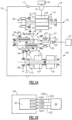
- FIG. 1A shows an integrated drive generator 20. As shown, housing portions 18 and 19 surround the integrated drive generator and a seal plate 17 sits between the housing portions 18 and 19.
- a gas turbine engine 22 may drive an input shaft 23 which selectively drives a disconnect assembly 26.
- the disconnect assembly 26 in turn, drives a carrier shaft 28, which drives a carrier in a gear differential 30.
- Gears 38 have a gear interface 42 with a first ring gear portion 40.
- Gears 36 have a gear interface 48 with a second ring gear portion 46.
- Ring gear portion 40 has a gear interface 50 with a main generator 51 having a drive gear 52.
- drive gear 52 When drive gear 52 is driven to rotate, it rotates a rotor 56 associated with a stator 58 of the main generator as well as an exciter rotor 60. Electric power is generated for a use 62, as known.
- the frequency of the generated electric power be at a desired frequency.
- a gear 15 that is part of the carrier has a gear interface 16 with a gear 13 driving a shaft 14 also within the speed trimmer.
- the speed trimmer 66 includes a variable unit 72 and a fixed unit 76.
- the units 72 and 76 may each be provided with a plurality of pistons and a swash plate arrangement. If the input speed of the gear 13 is too high, the speed of the gear 52 will also be too high, and hence, the speed trimmer 66 acts to lower the speed of the trim gear 46 which will drop the speed of gear 52. On the other hand, if the input speed is too low, the speed trimmer will increase the trim gear speed and he speed seen by gear 52 will increase.
- variable unit 72 receives an input through gear 13 that is proportional to the speed of the input shaft 23.
- the variable unit 72 also receives a control input from a control monitoring the speed of the generator rotor 56.
- the position of the swash plate in the variable unit 72 is changed to in turn change the speed and direction of the fixed unit 76.
- the fixed unit 76 can change the speed, and direction of rotation of the shaft 70, and this then provides control back through the trim ring gear 46 to change the speed reaching the generator.
- the speed trimmer 66 results in the frequency generated by the generator being closer to constant, and at the desired frequency.
- a permanent magnet generator 32 rotates with the ring gear 40.
- An accessory drive shaft 29 rotates with the ring gear 40 and drives a plurality of accessory gears 31.
- the operation of the integrated drive generator 20 is generally as known in the art. A worker of ordinary skill would recognize that the desired frequency and speed at use 62 would dictate a number of design functions.
- the power leaving the integrated drive generator 20 to the uses 62 must pass through a terminal at the area schematically shown at B.
- FIG 1B schematically shows detail of the area B.
- an output terminal 90 has a plurality of discrete connections shown schematically here. Three phases of power are supplied from electrical connections 100A, 100B, and 100C. A neutral lOON is also included. A plurality of wires 102N, A, B and C connect to the uses 62. Thus, power is supplied to uses 62.
- a terminal block cover 104 is identified by a body 105 ( Figures 2A -2E) and covers the connections 100A, 100B, 100C and 100N.
- Figure 2A shows the terminal block cover 104 having opposed thick ends 106 and intermediate connection channels 108A, 108B, 108C, and 108N for receiving the connections 100A, 100B, 100C, and 100N, respectively.
- Intermediate spacing channels 110AB, 110BC, and 110CN separate each of the connections to provide increased creep and lightning protection.
- a support, or terminal block 100 supports the connections 100A, B, C and N.
- Terminal block 100 has a support surface 100S with fingers 100F that extend into the spacing channels 110AB, 110BC, and 110CN.
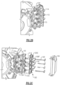
- Figure 2C is an assembly view showing the housing 18 and an exploded view showing the terminal block 100 and the terminal block cover 104 removed.
- Terminal lead assemblies 120 extend through holes in the terminal block, as will be explained below, and through holes 111 in the housing 18 to communicate with electrical connections 112A, 112B, 112C, and 112N, which extend from the generator.
- Figure 2B is an assembly view showing an inner end of the terminal lead assemblies 120 connected into the leads 112.
- a terminal support bracket 114 is also shown which includes clamps 115 to secure intermediate portions of the terminal lead assembly 120 to the housing 18.
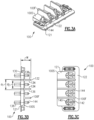
- FIG. 3A shows details of the terminal block 100 defined by a body 121.
- Phase lead connections 144 extend from the support surface 100S. There are four of the phase lead connections 144, which will each be associated with one of the connectors 100A, 100B, 100C, 100N. There are three fingers 100F. Further, a surface 122 is associated with a closed end of the cover 104. An open end of the cover 104 is on an opposed side of the terminal block 100 and it is through this open end where the electrical connections to phase lead wires 102 will be made. The fingers 100F separate connection channels.
- Figure 3B shows further details of the terminal block 100.
- a width W is defined between an inner surface 130 of the terminal block and to a spaced tip 132 of the fingers 100F, which is the location on the fingers 100F spaced from surface 130 by the greatest distance.
- a distance d 1 is defined between outer faces 136 of the fingers facing away from inner faces 134 defining a channel. The inner faces 134 are spaced by a distance d 2 . It should be understood that laterally outer fingers 100F also face inner surfaces of the cover 104.
- Inner guide structures 138 extend away from surface 130 and in a direction away from tip 132.
- Figure 3C shows further details with a recess 140 formed in surface 100S and receiving the phase lead connection 144 and a hole 142.
- the terminal lead assemblies 120 extend through the holes 142 to connect into the leads 112.
- W was 4.277 centimeters (1.684 inches). It should be understood that this in all dimensions in the application have a tolerance of +/- .025 centimeters (.010 inch) and the claims should be interpreted as such.
- the distance d 1 in one embodiment was 4.318 centimeters (1.700 inches) and the distance d 2 was 3.302 centimeters (1.300 inches).
- a ratio of W to d 2 is between 1.20 and 1.40.
- a ratio of W to d 1 is between 0.90 and 1.10, and a ratio of d 1 to d 2 is between 1.25 and 1.35.
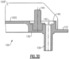
- Figure 3D is a cross-section through one of the recesses 140. As shown, the support surface 1005 is spaced from the inner surface 130 and the recess 140 extends towards surface 130 away from surface 100S.
- the phase lead connection 144 is shown as is the aperture 142, as well as the surface 122, that will receive the closed end of the terminal block cover.
- a method of replacing a terminal block includes the steps of removing an existing terminal block from an integrated drive generator including an input shaft connected to a carrier shaft.
- the carrier shaft is connected into a gear differential and into a main generator.
- the main generator is configured to provide three phases of electrical power to three electrical connections at a terminal connection, and the existing terminal block supporting said three electrical connections and a neutral connection.
- the existing terminal block supports is then replaced with a replacement terminal block cover, including a body having a support surface and an inner surface. There are four connection channels for receiving electric connections for each of three phases of power and a neutral. Three fingers extend from the support surface to separate the four connection channels.
Landscapes
- Engineering & Computer Science (AREA)
- Power Engineering (AREA)
- Chemical & Material Sciences (AREA)
- Combustion & Propulsion (AREA)
- Mechanical Engineering (AREA)
- General Engineering & Computer Science (AREA)
- Motor Or Generator Frames (AREA)
Claims (3)
- Anschlussleiste zur Verwendung in einem integrierten Antriebsgenerator, umfassend:einen Körper (121) mit einer äußeren Trägerfläche (100S), der sich zu einer Innenfläche (130) erstreckt, wobei vier Verbindungskanäle (108) zum Tragen elektrischer Verbindungen für jede von drei Stromphasen (100A, 100B, 100C) und einen Nullleiter (100N) vorliegen und Finger (100F) vorliegen, die zwischen benachbarten von jedem der vier Verbindungskanäle gebildet sind, wobei sich die Finger von der Trägerfläche weg in einer Richtung weg von der Innenfläche erstrecken;wobei Aussparungen (140) vorliegen, die sich in die Trägerfläche der Anschlussleiste erstrecken und eine Öffnung (142) beinhalten, durch die sich Leitungsbaugruppen erstrecken können, und eine Trägerstruktur, die sich in einer Richtung weg von der Innenfläche und über die Trägerfläche hinaus erstreckt;dadurch gekennzeichnet, dassAußenseiten der Finger um einen ersten Abstand (d1) von 1,7 Zoll (4,318 cm) +/- 0,01 Zoll (0,025 cm) voneinander beabstandet sind und ein zweiter Abstand (d2) von 1,3 Zoll (3,302 cm) +/- 0,01 Zoll (0,025 cm) zwischen den nach innen gerichteten Seiten der Finger vorliegt;wobei eine Breite (W) der Anschlussleiste zwischen der Innenfläche und einem Ende der Finger definiert ist, das am weitesten von der Innenfläche entfernt ist, wobei die Breite 1,684 Zoll (4,277 cm) +/- 0,01 Zoll (0,025 cm) beträgt;und Phasenleiterverbindungen (144) durch jeden der vier Verbindungskanäle vorliegen, wobei die Phasenleiterverbindungen auch in den Aussparungen (140) aufgenommen sind.
- Integrierter Antriebsgenerator, umfassend:
eine Eingangswelle (23), die mit einer Trägerwelle (28), wobei die Trägerwelle mit einem Getriebedifferenzial (30) verbunden ist, und in einen Hauptgenerator (51) verbunden ist, wobei der Hauptgenerator einen Stromausgang beinhaltet, der zum Bereitstellen von drei Phasen von elektrischem Strom an einer Steckdose konfiguriert ist, und wobei eine Anschlussleiste (100) nach einem der vorhergehenden Ansprüche vorliegt, die elektrische Verbindungen für die drei Phasen von elektrischem Strom und eine elektrische Verbindung für einen Nullleiter trägt. - Verfahren zum Ersetzen einer Anschlussleiste, das folgende Schritte umfasst:a) Entfernen einer vorhandenen Anschlussleiste von einem integrierten Antriebsgenerator, der eine Eingangswelle, die mit einer Trägerwelle, wobei die Trägerwelle mit einem Getriebedifferenzial verbunden ist, und in einen Hauptgenerator verbunden ist, beinhaltet, wobei der Hauptgenerator dazu konfiguriert ist, drei Phasen von elektrischem Strom an drei elektrische Verbindungen an einer Anschlussverbindung bereitzustellen, und wobei die vorhandene Anschlussleiste die drei elektrischen Verbindungen und eine Nullleiterverbindung trägt; undb) Ersetzen der vorhandenen Anschlussleiste durch eine Ersatzanschlussleiste mit einem Körper mit einer äußeren Trägerfläche, der sich bis zu einer Innenfläche erstreckt, wobei vier Verbindungskanäle zum Tragen elektrischer Verbindungen für jede von drei Stromphasen und einen Nullleiter vorhanden sind und Finger zwischen benachbarten von jedem der vier Verbindungskanäle gebildet sind, wobei sich die Finger von der Trägerfläche weg in einer Richtung weg von der Innenfläche erstrecken; dadurch gekennzeichnet, dass Außenseiten der Finger um einen ersten Abstand (d1) von 1,7 Zoll (4,318 cm) +/- 0,01 Zoll (0,025 cm) beabstandet sind und ein zweiter Abstand (d2) von 1,3 Zoll (3,302 cm) +/- 0,01 Zoll (0,025 cm) zwischen den nach innen gerichteten Seiten der Finger vorliegt;wobei eine Breite (W) der Anschlussleiste zwischen der Innenfläche und einem Ende der Finger definiert ist, das am weitesten von der Innenfläche entfernt ist und die Breite 1,684 Zoll (4,277 cm) +/- 0,01 Zoll (0,025 cm) beträgt; undwobei Aussparungen vorliegen, die sich in die Trägerfläche der Anschlussleiste erstrecken und eine Öffnung beinhalten, durch die sich Leitungsbaugruppen erstrecken können, und eine Trägerstruktur, die sich in einer Richtung weg von der Innenfläche und über die Trägerfläche hinaus erstreckt, und wobei Phasenleiterverbindungen (144) durch jeden der vier Verbindungskanäle vorliegen, wobei die Phasenleiterverbindungen auch in den Aussparungen (140) aufgenommen sind.
Applications Claiming Priority (1)
| Application Number | Priority Date | Filing Date | Title |
|---|---|---|---|
| US15/868,217 US10763722B2 (en) | 2018-01-11 | 2018-01-11 | Terminal block for use in integrated drive generator |
Publications (2)
| Publication Number | Publication Date |
|---|---|
| EP3512043A1 EP3512043A1 (de) | 2019-07-17 |
| EP3512043B1 true EP3512043B1 (de) | 2024-04-24 |
Family
ID=65019424
Family Applications (1)
| Application Number | Title | Priority Date | Filing Date |
|---|---|---|---|
| EP19151460.3A Active EP3512043B1 (de) | 2018-01-11 | 2019-01-11 | Anschlussleiste zur verwendung in einem integrierten antriebsgenerator |
Country Status (2)
| Country | Link |
|---|---|
| US (1) | US10763722B2 (de) |
| EP (1) | EP3512043B1 (de) |
Families Citing this family (4)
| Publication number | Priority date | Publication date | Assignee | Title |
|---|---|---|---|---|
| US11171429B2 (en) * | 2020-01-07 | 2021-11-09 | Hamilton Sundstrand Corporation | Terminal block assemblies |
| CN114844285B (zh) * | 2022-05-27 | 2025-09-02 | 奇瑞汽车股份有限公司 | 电机接线座及车辆 |
| JP2024077890A (ja) * | 2022-11-29 | 2024-06-10 | トヨタ自動車株式会社 | 端子台 |
| US12469992B2 (en) | 2023-02-07 | 2025-11-11 | Hamilton Sundstrand Corporation | Terminal block and cover for arcing mitigation |
Family Cites Families (9)
| Publication number | Priority date | Publication date | Assignee | Title |
|---|---|---|---|---|
| US3576143A (en) * | 1969-09-05 | 1971-04-27 | Sundstrand Corp | Constant speed drive and generator |
| US6897584B2 (en) | 2002-04-25 | 2005-05-24 | Honeywell International Inc. | High power terminal block assembly for generators and method of assembling and installing the same |
| KR100854383B1 (ko) * | 2007-03-08 | 2008-09-02 | 엘에스산전 주식회사 | 일체형 도어를 갖는 회로 차단기의 외함 |
| US8313351B2 (en) | 2011-01-21 | 2012-11-20 | Hamilton Sundstrand Corporation | High altitude, high voltage terminal block assembly |
| EP2636872B1 (de) | 2012-03-05 | 2019-05-01 | Hamilton Sundstrand Corporation | Antriebsanordnung einer Turbomaschine |
| JP5650253B2 (ja) * | 2013-01-15 | 2015-01-07 | トヨタ自動車株式会社 | パワーケーブルの接続構造 |
| US9472996B2 (en) * | 2013-04-15 | 2016-10-18 | Hamilton Sundstrand Corporation | Terminal assembly |
| US20140305692A1 (en) * | 2013-04-15 | 2014-10-16 | Hamilton Sundstrand Corporation | Terminal block cover |
| US20160348788A1 (en) | 2014-12-12 | 2016-12-01 | Hamilton Sundstrand Corporation | Integrated APU Generator Constant Speed Drive |
-
2018
- 2018-01-11 US US15/868,217 patent/US10763722B2/en active Active
-
2019
- 2019-01-11 EP EP19151460.3A patent/EP3512043B1/de active Active
Also Published As
| Publication number | Publication date |
|---|---|
| EP3512043A1 (de) | 2019-07-17 |
| US20190214881A1 (en) | 2019-07-11 |
| US10763722B2 (en) | 2020-09-01 |
Similar Documents
| Publication | Publication Date | Title |
|---|---|---|
| EP3512043B1 (de) | Anschlussleiste zur verwendung in einem integrierten antriebsgenerator | |
| EP3509196B1 (de) | Anschlussleitungsanordnung zur verwendung in einem integrierten antriebsgenerator | |
| EP3511550B1 (de) | Anschlussleitungsträger zur verwendung in einem integrierten antriebsgenerator | |
| EP3490117B1 (de) | Anschlussleistenabdeckung zur verwendung in einem integrierten antriebsgenerator | |
| EP3509194B1 (de) | Blechpaket für den hauptgeneratorläufer in einem integrierten antriebsgenerator | |
| EP3509199B1 (de) | Hauptgeneratorstatorhülse für integrierten antriebsgenerator | |
| EP3486528B1 (de) | Regler- und inversionspumpenantriebzahnrad | |
| EP3467331B1 (de) | Trennwelle für einen integrierten antriebsgenerator | |
| EP3508746B1 (de) | Eingangswelle zur verwendung in einem integrierten antriebsgetriebe | |
| EP3467349A1 (de) | Hilfsantriebsgetriebe für integrierten antriebsgenerator | |
| EP3473896B1 (de) | Dichtungsplatte zwischen zwei gehäuseabschnitten in einem integrierten antriebsgenerator | |
| EP3489532B1 (de) | Verschleissring für einen integrierten antriebsgenerator | |
| EP3508757B1 (de) | Integrierter antriebsgenerator und entsprechendes verfahren zum ersetzen eines reglergetriebes in einem solchen generator | |
| EP3486529B1 (de) | Antriebszahnrad einer rückförder-/ladepumpe für integrierten antriebsgenerator | |
| EP3502514B1 (de) | Abgangszahnkranz für integrierten antriebsgenerator | |
| EP3508758B1 (de) | Angetriebenes zahnrad für generator eines integrierten antriebsgenerator |
Legal Events
| Date | Code | Title | Description |
|---|---|---|---|
| PUAI | Public reference made under article 153(3) epc to a published international application that has entered the european phase |
Free format text: ORIGINAL CODE: 0009012 |
|
| STAA | Information on the status of an ep patent application or granted ep patent |
Free format text: STATUS: THE APPLICATION HAS BEEN PUBLISHED |
|
| AK | Designated contracting states |
Kind code of ref document: A1 Designated state(s): AL AT BE BG CH CY CZ DE DK EE ES FI FR GB GR HR HU IE IS IT LI LT LU LV MC MK MT NL NO PL PT RO RS SE SI SK SM TR |
|
| AX | Request for extension of the european patent |
Extension state: BA ME |
|
| STAA | Information on the status of an ep patent application or granted ep patent |
Free format text: STATUS: REQUEST FOR EXAMINATION WAS MADE |
|
| 17P | Request for examination filed |
Effective date: 20191213 |
|
| RBV | Designated contracting states (corrected) |
Designated state(s): AL AT BE BG CH CY CZ DE DK EE ES FI FR GB GR HR HU IE IS IT LI LT LU LV MC MK MT NL NO PL PT RO RS SE SI SK SM TR |
|
| STAA | Information on the status of an ep patent application or granted ep patent |
Free format text: STATUS: EXAMINATION IS IN PROGRESS |
|
| 17Q | First examination report despatched |
Effective date: 20200602 |
|
| GRAP | Despatch of communication of intention to grant a patent |
Free format text: ORIGINAL CODE: EPIDOSNIGR1 |
|
| STAA | Information on the status of an ep patent application or granted ep patent |
Free format text: STATUS: GRANT OF PATENT IS INTENDED |
|
| INTG | Intention to grant announced |
Effective date: 20240124 |
|
| GRAS | Grant fee paid |
Free format text: ORIGINAL CODE: EPIDOSNIGR3 |
|
| GRAA | (expected) grant |
Free format text: ORIGINAL CODE: 0009210 |
|
| STAA | Information on the status of an ep patent application or granted ep patent |
Free format text: STATUS: THE PATENT HAS BEEN GRANTED |
|
| AK | Designated contracting states |
Kind code of ref document: B1 Designated state(s): AL AT BE BG CH CY CZ DE DK EE ES FI FR GB GR HR HU IE IS IT LI LT LU LV MC MK MT NL NO PL PT RO RS SE SI SK SM TR |
|
| REG | Reference to a national code |
Ref country code: GB Ref legal event code: FG4D |
|
| REG | Reference to a national code |
Ref country code: CH Ref legal event code: EP |
|
| REG | Reference to a national code |
Ref country code: DE Ref legal event code: R096 Ref document number: 602019050710 Country of ref document: DE |
|
| REG | Reference to a national code |
Ref country code: IE Ref legal event code: FG4D |
|
| REG | Reference to a national code |
Ref country code: LT Ref legal event code: MG9D |
|
| REG | Reference to a national code |
Ref country code: NL Ref legal event code: MP Effective date: 20240424 |
|
| REG | Reference to a national code |
Ref country code: AT Ref legal event code: MK05 Ref document number: 1680644 Country of ref document: AT Kind code of ref document: T Effective date: 20240424 |
|
| PG25 | Lapsed in a contracting state [announced via postgrant information from national office to epo] |
Ref country code: NL Free format text: LAPSE BECAUSE OF FAILURE TO SUBMIT A TRANSLATION OF THE DESCRIPTION OR TO PAY THE FEE WITHIN THE PRESCRIBED TIME-LIMIT Effective date: 20240424 |
|
| PG25 | Lapsed in a contracting state [announced via postgrant information from national office to epo] |
Ref country code: NL Free format text: LAPSE BECAUSE OF FAILURE TO SUBMIT A TRANSLATION OF THE DESCRIPTION OR TO PAY THE FEE WITHIN THE PRESCRIBED TIME-LIMIT Effective date: 20240424 |
|
| PG25 | Lapsed in a contracting state [announced via postgrant information from national office to epo] |
Ref country code: IS Free format text: LAPSE BECAUSE OF FAILURE TO SUBMIT A TRANSLATION OF THE DESCRIPTION OR TO PAY THE FEE WITHIN THE PRESCRIBED TIME-LIMIT Effective date: 20240824 |
|
| PG25 | Lapsed in a contracting state [announced via postgrant information from national office to epo] |
Ref country code: BG Free format text: LAPSE BECAUSE OF FAILURE TO SUBMIT A TRANSLATION OF THE DESCRIPTION OR TO PAY THE FEE WITHIN THE PRESCRIBED TIME-LIMIT Effective date: 20240424 |
|
| PG25 | Lapsed in a contracting state [announced via postgrant information from national office to epo] |
Ref country code: FI Free format text: LAPSE BECAUSE OF FAILURE TO SUBMIT A TRANSLATION OF THE DESCRIPTION OR TO PAY THE FEE WITHIN THE PRESCRIBED TIME-LIMIT Effective date: 20240424 Ref country code: HR Free format text: LAPSE BECAUSE OF FAILURE TO SUBMIT A TRANSLATION OF THE DESCRIPTION OR TO PAY THE FEE WITHIN THE PRESCRIBED TIME-LIMIT Effective date: 20240424 |
|
| PG25 | Lapsed in a contracting state [announced via postgrant information from national office to epo] |
Ref country code: GR Free format text: LAPSE BECAUSE OF FAILURE TO SUBMIT A TRANSLATION OF THE DESCRIPTION OR TO PAY THE FEE WITHIN THE PRESCRIBED TIME-LIMIT Effective date: 20240725 |
|
| PG25 | Lapsed in a contracting state [announced via postgrant information from national office to epo] |
Ref country code: PT Free format text: LAPSE BECAUSE OF FAILURE TO SUBMIT A TRANSLATION OF THE DESCRIPTION OR TO PAY THE FEE WITHIN THE PRESCRIBED TIME-LIMIT Effective date: 20240826 |
|
| PG25 | Lapsed in a contracting state [announced via postgrant information from national office to epo] |
Ref country code: ES Free format text: LAPSE BECAUSE OF FAILURE TO SUBMIT A TRANSLATION OF THE DESCRIPTION OR TO PAY THE FEE WITHIN THE PRESCRIBED TIME-LIMIT Effective date: 20240424 |
|
| PG25 | Lapsed in a contracting state [announced via postgrant information from national office to epo] |
Ref country code: AT Free format text: LAPSE BECAUSE OF FAILURE TO SUBMIT A TRANSLATION OF THE DESCRIPTION OR TO PAY THE FEE WITHIN THE PRESCRIBED TIME-LIMIT Effective date: 20240424 |
|
| PG25 | Lapsed in a contracting state [announced via postgrant information from national office to epo] |
Ref country code: PL Free format text: LAPSE BECAUSE OF FAILURE TO SUBMIT A TRANSLATION OF THE DESCRIPTION OR TO PAY THE FEE WITHIN THE PRESCRIBED TIME-LIMIT Effective date: 20240424 |
|
| PG25 | Lapsed in a contracting state [announced via postgrant information from national office to epo] |
Ref country code: LV Free format text: LAPSE BECAUSE OF FAILURE TO SUBMIT A TRANSLATION OF THE DESCRIPTION OR TO PAY THE FEE WITHIN THE PRESCRIBED TIME-LIMIT Effective date: 20240424 |
|
| PG25 | Lapsed in a contracting state [announced via postgrant information from national office to epo] |
Ref country code: PT Free format text: LAPSE BECAUSE OF FAILURE TO SUBMIT A TRANSLATION OF THE DESCRIPTION OR TO PAY THE FEE WITHIN THE PRESCRIBED TIME-LIMIT Effective date: 20240826 Ref country code: PL Free format text: LAPSE BECAUSE OF FAILURE TO SUBMIT A TRANSLATION OF THE DESCRIPTION OR TO PAY THE FEE WITHIN THE PRESCRIBED TIME-LIMIT Effective date: 20240424 Ref country code: NO Free format text: LAPSE BECAUSE OF FAILURE TO SUBMIT A TRANSLATION OF THE DESCRIPTION OR TO PAY THE FEE WITHIN THE PRESCRIBED TIME-LIMIT Effective date: 20240724 Ref country code: LV Free format text: LAPSE BECAUSE OF FAILURE TO SUBMIT A TRANSLATION OF THE DESCRIPTION OR TO PAY THE FEE WITHIN THE PRESCRIBED TIME-LIMIT Effective date: 20240424 Ref country code: IS Free format text: LAPSE BECAUSE OF FAILURE TO SUBMIT A TRANSLATION OF THE DESCRIPTION OR TO PAY THE FEE WITHIN THE PRESCRIBED TIME-LIMIT Effective date: 20240824 Ref country code: HR Free format text: LAPSE BECAUSE OF FAILURE TO SUBMIT A TRANSLATION OF THE DESCRIPTION OR TO PAY THE FEE WITHIN THE PRESCRIBED TIME-LIMIT Effective date: 20240424 Ref country code: GR Free format text: LAPSE BECAUSE OF FAILURE TO SUBMIT A TRANSLATION OF THE DESCRIPTION OR TO PAY THE FEE WITHIN THE PRESCRIBED TIME-LIMIT Effective date: 20240725 Ref country code: FI Free format text: LAPSE BECAUSE OF FAILURE TO SUBMIT A TRANSLATION OF THE DESCRIPTION OR TO PAY THE FEE WITHIN THE PRESCRIBED TIME-LIMIT Effective date: 20240424 Ref country code: ES Free format text: LAPSE BECAUSE OF FAILURE TO SUBMIT A TRANSLATION OF THE DESCRIPTION OR TO PAY THE FEE WITHIN THE PRESCRIBED TIME-LIMIT Effective date: 20240424 Ref country code: BG Free format text: LAPSE BECAUSE OF FAILURE TO SUBMIT A TRANSLATION OF THE DESCRIPTION OR TO PAY THE FEE WITHIN THE PRESCRIBED TIME-LIMIT Effective date: 20240424 Ref country code: AT Free format text: LAPSE BECAUSE OF FAILURE TO SUBMIT A TRANSLATION OF THE DESCRIPTION OR TO PAY THE FEE WITHIN THE PRESCRIBED TIME-LIMIT Effective date: 20240424 Ref country code: RS Free format text: LAPSE BECAUSE OF FAILURE TO SUBMIT A TRANSLATION OF THE DESCRIPTION OR TO PAY THE FEE WITHIN THE PRESCRIBED TIME-LIMIT Effective date: 20240724 |
|
| PG25 | Lapsed in a contracting state [announced via postgrant information from national office to epo] |
Ref country code: DK Free format text: LAPSE BECAUSE OF FAILURE TO SUBMIT A TRANSLATION OF THE DESCRIPTION OR TO PAY THE FEE WITHIN THE PRESCRIBED TIME-LIMIT Effective date: 20240424 |
|
| PG25 | Lapsed in a contracting state [announced via postgrant information from national office to epo] |
Ref country code: EE Free format text: LAPSE BECAUSE OF FAILURE TO SUBMIT A TRANSLATION OF THE DESCRIPTION OR TO PAY THE FEE WITHIN THE PRESCRIBED TIME-LIMIT Effective date: 20240424 |
|
| PG25 | Lapsed in a contracting state [announced via postgrant information from national office to epo] |
Ref country code: CZ Free format text: LAPSE BECAUSE OF FAILURE TO SUBMIT A TRANSLATION OF THE DESCRIPTION OR TO PAY THE FEE WITHIN THE PRESCRIBED TIME-LIMIT Effective date: 20240424 |
|
| PG25 | Lapsed in a contracting state [announced via postgrant information from national office to epo] |
Ref country code: SK Free format text: LAPSE BECAUSE OF FAILURE TO SUBMIT A TRANSLATION OF THE DESCRIPTION OR TO PAY THE FEE WITHIN THE PRESCRIBED TIME-LIMIT Effective date: 20240424 Ref country code: RO Free format text: LAPSE BECAUSE OF FAILURE TO SUBMIT A TRANSLATION OF THE DESCRIPTION OR TO PAY THE FEE WITHIN THE PRESCRIBED TIME-LIMIT Effective date: 20240424 |
|
| REG | Reference to a national code |
Ref country code: DE Ref legal event code: R097 Ref document number: 602019050710 Country of ref document: DE |
|
| PG25 | Lapsed in a contracting state [announced via postgrant information from national office to epo] |
Ref country code: SM Free format text: LAPSE BECAUSE OF FAILURE TO SUBMIT A TRANSLATION OF THE DESCRIPTION OR TO PAY THE FEE WITHIN THE PRESCRIBED TIME-LIMIT Effective date: 20240424 |
|
| PG25 | Lapsed in a contracting state [announced via postgrant information from national office to epo] |
Ref country code: SM Free format text: LAPSE BECAUSE OF FAILURE TO SUBMIT A TRANSLATION OF THE DESCRIPTION OR TO PAY THE FEE WITHIN THE PRESCRIBED TIME-LIMIT Effective date: 20240424 Ref country code: SK Free format text: LAPSE BECAUSE OF FAILURE TO SUBMIT A TRANSLATION OF THE DESCRIPTION OR TO PAY THE FEE WITHIN THE PRESCRIBED TIME-LIMIT Effective date: 20240424 Ref country code: RO Free format text: LAPSE BECAUSE OF FAILURE TO SUBMIT A TRANSLATION OF THE DESCRIPTION OR TO PAY THE FEE WITHIN THE PRESCRIBED TIME-LIMIT Effective date: 20240424 Ref country code: EE Free format text: LAPSE BECAUSE OF FAILURE TO SUBMIT A TRANSLATION OF THE DESCRIPTION OR TO PAY THE FEE WITHIN THE PRESCRIBED TIME-LIMIT Effective date: 20240424 Ref country code: DK Free format text: LAPSE BECAUSE OF FAILURE TO SUBMIT A TRANSLATION OF THE DESCRIPTION OR TO PAY THE FEE WITHIN THE PRESCRIBED TIME-LIMIT Effective date: 20240424 Ref country code: CZ Free format text: LAPSE BECAUSE OF FAILURE TO SUBMIT A TRANSLATION OF THE DESCRIPTION OR TO PAY THE FEE WITHIN THE PRESCRIBED TIME-LIMIT Effective date: 20240424 |
|
| PLBE | No opposition filed within time limit |
Free format text: ORIGINAL CODE: 0009261 |
|
| STAA | Information on the status of an ep patent application or granted ep patent |
Free format text: STATUS: NO OPPOSITION FILED WITHIN TIME LIMIT |
|
| 26N | No opposition filed |
Effective date: 20250127 |
|
| PG25 | Lapsed in a contracting state [announced via postgrant information from national office to epo] |
Ref country code: SI Free format text: LAPSE BECAUSE OF FAILURE TO SUBMIT A TRANSLATION OF THE DESCRIPTION OR TO PAY THE FEE WITHIN THE PRESCRIBED TIME-LIMIT Effective date: 20240424 |
|
| REG | Reference to a national code |
Ref country code: CH Ref legal event code: PL |
|
| PG25 | Lapsed in a contracting state [announced via postgrant information from national office to epo] |
Ref country code: SE Free format text: LAPSE BECAUSE OF FAILURE TO SUBMIT A TRANSLATION OF THE DESCRIPTION OR TO PAY THE FEE WITHIN THE PRESCRIBED TIME-LIMIT Effective date: 20240424 |
|
| PG25 | Lapsed in a contracting state [announced via postgrant information from national office to epo] |
Ref country code: MC Free format text: LAPSE BECAUSE OF FAILURE TO SUBMIT A TRANSLATION OF THE DESCRIPTION OR TO PAY THE FEE WITHIN THE PRESCRIBED TIME-LIMIT Effective date: 20240424 Ref country code: LU Free format text: LAPSE BECAUSE OF NON-PAYMENT OF DUE FEES Effective date: 20250111 |
|
| PG25 | Lapsed in a contracting state [announced via postgrant information from national office to epo] |
Ref country code: BE Free format text: LAPSE BECAUSE OF NON-PAYMENT OF DUE FEES Effective date: 20250131 |
|
| PG25 | Lapsed in a contracting state [announced via postgrant information from national office to epo] |
Ref country code: CH Free format text: LAPSE BECAUSE OF NON-PAYMENT OF DUE FEES Effective date: 20250131 |
|
| REG | Reference to a national code |
Ref country code: BE Ref legal event code: MM Effective date: 20250131 |
|
| PGFP | Annual fee paid to national office [announced via postgrant information from national office to epo] |
Ref country code: GB Payment date: 20251220 Year of fee payment: 8 |
|
| PGFP | Annual fee paid to national office [announced via postgrant information from national office to epo] |
Ref country code: FR Payment date: 20251217 Year of fee payment: 8 |
|
| PG25 | Lapsed in a contracting state [announced via postgrant information from national office to epo] |
Ref country code: IE Free format text: LAPSE BECAUSE OF NON-PAYMENT OF DUE FEES Effective date: 20250111 |
|
| PG25 | Lapsed in a contracting state [announced via postgrant information from national office to epo] |
Ref country code: IT Free format text: LAPSE BECAUSE OF FAILURE TO SUBMIT A TRANSLATION OF THE DESCRIPTION OR TO PAY THE FEE WITHIN THE PRESCRIBED TIME-LIMIT Effective date: 20240424 |
|
| PGFP | Annual fee paid to national office [announced via postgrant information from national office to epo] |
Ref country code: DE Payment date: 20251217 Year of fee payment: 8 |