EP3511997B1 - Batteriesystem - Google Patents
Batteriesystem Download PDFInfo
- Publication number
- EP3511997B1 EP3511997B1 EP19158244.4A EP19158244A EP3511997B1 EP 3511997 B1 EP3511997 B1 EP 3511997B1 EP 19158244 A EP19158244 A EP 19158244A EP 3511997 B1 EP3511997 B1 EP 3511997B1
- Authority
- EP
- European Patent Office
- Prior art keywords
- battery module
- battery
- leakage current
- battery system
- acicular
- Prior art date
- Legal status (The legal status is an assumption and is not a legal conclusion. Google has not performed a legal analysis and makes no representation as to the accuracy of the status listed.)
- Active
Links
Images



Classifications
-
- H—ELECTRICITY
- H01—ELECTRIC ELEMENTS
- H01M—PROCESSES OR MEANS, e.g. BATTERIES, FOR THE DIRECT CONVERSION OF CHEMICAL ENERGY INTO ELECTRICAL ENERGY
- H01M10/00—Secondary cells; Manufacture thereof
- H01M10/42—Methods or arrangements for servicing or maintenance of secondary cells or secondary half-cells
- H01M10/425—Structural combination with electronic components, e.g. electronic circuits integrated to the outside of the casing
-
- H—ELECTRICITY
- H01—ELECTRIC ELEMENTS
- H01M—PROCESSES OR MEANS, e.g. BATTERIES, FOR THE DIRECT CONVERSION OF CHEMICAL ENERGY INTO ELECTRICAL ENERGY
- H01M10/00—Secondary cells; Manufacture thereof
- H01M10/60—Heating or cooling; Temperature control
- H01M10/61—Types of temperature control
- H01M10/613—Cooling or keeping cold
-
- H—ELECTRICITY
- H01—ELECTRIC ELEMENTS
- H01M—PROCESSES OR MEANS, e.g. BATTERIES, FOR THE DIRECT CONVERSION OF CHEMICAL ENERGY INTO ELECTRICAL ENERGY
- H01M10/00—Secondary cells; Manufacture thereof
- H01M10/60—Heating or cooling; Temperature control
- H01M10/62—Heating or cooling; Temperature control specially adapted for specific applications
- H01M10/625—Vehicles
-
- B—PERFORMING OPERATIONS; TRANSPORTING
- B60—VEHICLES IN GENERAL
- B60L—PROPULSION OF ELECTRICALLY-PROPELLED VEHICLES; SUPPLYING ELECTRIC POWER FOR AUXILIARY EQUIPMENT OF ELECTRICALLY-PROPELLED VEHICLES; ELECTRODYNAMIC BRAKE SYSTEMS FOR VEHICLES IN GENERAL; MAGNETIC SUSPENSION OR LEVITATION FOR VEHICLES; MONITORING OPERATING VARIABLES OF ELECTRICALLY-PROPELLED VEHICLES; ELECTRIC SAFETY DEVICES FOR ELECTRICALLY-PROPELLED VEHICLES
- B60L3/00—Electric devices on electrically-propelled vehicles for safety purposes; Monitoring operating variables, e.g. speed, deceleration or energy consumption
- B60L3/0023—Detecting, eliminating, remedying or compensating for drive train abnormalities, e.g. failures within the drive train
- B60L3/0069—Detecting, eliminating, remedying or compensating for drive train abnormalities, e.g. failures within the drive train relating to the isolation, e.g. ground fault or leak current
-
- B—PERFORMING OPERATIONS; TRANSPORTING
- B60—VEHICLES IN GENERAL
- B60L—PROPULSION OF ELECTRICALLY-PROPELLED VEHICLES; SUPPLYING ELECTRIC POWER FOR AUXILIARY EQUIPMENT OF ELECTRICALLY-PROPELLED VEHICLES; ELECTRODYNAMIC BRAKE SYSTEMS FOR VEHICLES IN GENERAL; MAGNETIC SUSPENSION OR LEVITATION FOR VEHICLES; MONITORING OPERATING VARIABLES OF ELECTRICALLY-PROPELLED VEHICLES; ELECTRIC SAFETY DEVICES FOR ELECTRICALLY-PROPELLED VEHICLES
- B60L58/00—Methods or circuit arrangements for monitoring or controlling batteries or fuel cells, specially adapted for electric vehicles
- B60L58/10—Methods or circuit arrangements for monitoring or controlling batteries or fuel cells, specially adapted for electric vehicles for monitoring or controlling batteries
- B60L58/12—Methods or circuit arrangements for monitoring or controlling batteries or fuel cells, specially adapted for electric vehicles for monitoring or controlling batteries responding to state of charge [SoC]
-
- B—PERFORMING OPERATIONS; TRANSPORTING
- B60—VEHICLES IN GENERAL
- B60L—PROPULSION OF ELECTRICALLY-PROPELLED VEHICLES; SUPPLYING ELECTRIC POWER FOR AUXILIARY EQUIPMENT OF ELECTRICALLY-PROPELLED VEHICLES; ELECTRODYNAMIC BRAKE SYSTEMS FOR VEHICLES IN GENERAL; MAGNETIC SUSPENSION OR LEVITATION FOR VEHICLES; MONITORING OPERATING VARIABLES OF ELECTRICALLY-PROPELLED VEHICLES; ELECTRIC SAFETY DEVICES FOR ELECTRICALLY-PROPELLED VEHICLES
- B60L58/00—Methods or circuit arrangements for monitoring or controlling batteries or fuel cells, specially adapted for electric vehicles
- B60L58/10—Methods or circuit arrangements for monitoring or controlling batteries or fuel cells, specially adapted for electric vehicles for monitoring or controlling batteries
- B60L58/24—Methods or circuit arrangements for monitoring or controlling batteries or fuel cells, specially adapted for electric vehicles for monitoring or controlling batteries for controlling the temperature of batteries
- B60L58/26—Methods or circuit arrangements for monitoring or controlling batteries or fuel cells, specially adapted for electric vehicles for monitoring or controlling batteries for controlling the temperature of batteries by cooling
-
- H—ELECTRICITY
- H01—ELECTRIC ELEMENTS
- H01M—PROCESSES OR MEANS, e.g. BATTERIES, FOR THE DIRECT CONVERSION OF CHEMICAL ENERGY INTO ELECTRICAL ENERGY
- H01M10/00—Secondary cells; Manufacture thereof
- H01M10/42—Methods or arrangements for servicing or maintenance of secondary cells or secondary half-cells
- H01M10/48—Accumulators combined with arrangements for measuring, testing or indicating the condition of cells, e.g. the level or density of the electrolyte
- H01M10/482—Accumulators combined with arrangements for measuring, testing or indicating the condition of cells, e.g. the level or density of the electrolyte for several batteries or cells simultaneously or sequentially
-
- H—ELECTRICITY
- H01—ELECTRIC ELEMENTS
- H01M—PROCESSES OR MEANS, e.g. BATTERIES, FOR THE DIRECT CONVERSION OF CHEMICAL ENERGY INTO ELECTRICAL ENERGY
- H01M10/00—Secondary cells; Manufacture thereof
- H01M10/60—Heating or cooling; Temperature control
- H01M10/65—Means for temperature control structurally associated with the cells
- H01M10/655—Solid structures for heat exchange or heat conduction
- H01M10/6551—Surfaces specially adapted for heat dissipation or radiation, e.g. fins or coatings
-
- H—ELECTRICITY
- H01—ELECTRIC ELEMENTS
- H01M—PROCESSES OR MEANS, e.g. BATTERIES, FOR THE DIRECT CONVERSION OF CHEMICAL ENERGY INTO ELECTRICAL ENERGY
- H01M10/00—Secondary cells; Manufacture thereof
- H01M10/60—Heating or cooling; Temperature control
- H01M10/65—Means for temperature control structurally associated with the cells
- H01M10/655—Solid structures for heat exchange or heat conduction
- H01M10/6556—Solid parts with flow channel passages or pipes for heat exchange
-
- H—ELECTRICITY
- H01—ELECTRIC ELEMENTS
- H01M—PROCESSES OR MEANS, e.g. BATTERIES, FOR THE DIRECT CONVERSION OF CHEMICAL ENERGY INTO ELECTRICAL ENERGY
- H01M10/00—Secondary cells; Manufacture thereof
- H01M10/60—Heating or cooling; Temperature control
- H01M10/65—Means for temperature control structurally associated with the cells
- H01M10/656—Means for temperature control structurally associated with the cells characterised by the type of heat-exchange fluid
- H01M10/6567—Liquids
-
- H—ELECTRICITY
- H01—ELECTRIC ELEMENTS
- H01M—PROCESSES OR MEANS, e.g. BATTERIES, FOR THE DIRECT CONVERSION OF CHEMICAL ENERGY INTO ELECTRICAL ENERGY
- H01M10/00—Secondary cells; Manufacture thereof
- H01M10/60—Heating or cooling; Temperature control
- H01M10/65—Means for temperature control structurally associated with the cells
- H01M10/656—Means for temperature control structurally associated with the cells characterised by the type of heat-exchange fluid
- H01M10/6567—Liquids
- H01M10/6568—Liquids characterised by flow circuits, e.g. loops, located externally to the cells or cell casings
-
- H—ELECTRICITY
- H01—ELECTRIC ELEMENTS
- H01M—PROCESSES OR MEANS, e.g. BATTERIES, FOR THE DIRECT CONVERSION OF CHEMICAL ENERGY INTO ELECTRICAL ENERGY
- H01M50/00—Constructional details or processes of manufacture of the non-active parts of electrochemical cells other than fuel cells, e.g. hybrid cells
- H01M50/20—Mountings; Secondary casings or frames; Racks, modules or packs; Suspension devices; Shock absorbers; Transport or carrying devices; Holders
- H01M50/258—Modular batteries; Casings provided with means for assembling
-
- H—ELECTRICITY
- H01—ELECTRIC ELEMENTS
- H01M—PROCESSES OR MEANS, e.g. BATTERIES, FOR THE DIRECT CONVERSION OF CHEMICAL ENERGY INTO ELECTRICAL ENERGY
- H01M50/00—Constructional details or processes of manufacture of the non-active parts of electrochemical cells other than fuel cells, e.g. hybrid cells
- H01M50/50—Current conducting connections for cells or batteries
- H01M50/572—Means for preventing undesired use or discharge
-
- H—ELECTRICITY
- H01—ELECTRIC ELEMENTS
- H01M—PROCESSES OR MEANS, e.g. BATTERIES, FOR THE DIRECT CONVERSION OF CHEMICAL ENERGY INTO ELECTRICAL ENERGY
- H01M50/00—Constructional details or processes of manufacture of the non-active parts of electrochemical cells other than fuel cells, e.g. hybrid cells
- H01M50/50—Current conducting connections for cells or batteries
- H01M50/572—Means for preventing undesired use or discharge
- H01M50/574—Devices or arrangements for the interruption of current
-
- H—ELECTRICITY
- H02—GENERATION; CONVERSION OR DISTRIBUTION OF ELECTRIC POWER
- H02H—EMERGENCY PROTECTIVE CIRCUIT ARRANGEMENTS
- H02H7/00—Emergency protective circuit arrangements specially adapted for specific types of electric machines or apparatus or for sectionalised protection of cable or line systems, and effecting automatic switching in the event of an undesired change from normal working conditions
- H02H7/18—Emergency protective circuit arrangements specially adapted for specific types of electric machines or apparatus or for sectionalised protection of cable or line systems, and effecting automatic switching in the event of an undesired change from normal working conditions for batteries; for accumulators
-
- H—ELECTRICITY
- H01—ELECTRIC ELEMENTS
- H01M—PROCESSES OR MEANS, e.g. BATTERIES, FOR THE DIRECT CONVERSION OF CHEMICAL ENERGY INTO ELECTRICAL ENERGY
- H01M2200/00—Safety devices for primary or secondary batteries
-
- H—ELECTRICITY
- H01—ELECTRIC ELEMENTS
- H01M—PROCESSES OR MEANS, e.g. BATTERIES, FOR THE DIRECT CONVERSION OF CHEMICAL ENERGY INTO ELECTRICAL ENERGY
- H01M2220/00—Batteries for particular applications
- H01M2220/20—Batteries in motive systems, e.g. vehicle, ship, plane
-
- H—ELECTRICITY
- H01—ELECTRIC ELEMENTS
- H01M—PROCESSES OR MEANS, e.g. BATTERIES, FOR THE DIRECT CONVERSION OF CHEMICAL ENERGY INTO ELECTRICAL ENERGY
- H01M50/00—Constructional details or processes of manufacture of the non-active parts of electrochemical cells other than fuel cells, e.g. hybrid cells
- H01M50/20—Mountings; Secondary casings or frames; Racks, modules or packs; Suspension devices; Shock absorbers; Transport or carrying devices; Holders
- H01M50/204—Racks, modules or packs for multiple batteries or multiple cells
-
- H—ELECTRICITY
- H01—ELECTRIC ELEMENTS
- H01M—PROCESSES OR MEANS, e.g. BATTERIES, FOR THE DIRECT CONVERSION OF CHEMICAL ENERGY INTO ELECTRICAL ENERGY
- H01M50/00—Constructional details or processes of manufacture of the non-active parts of electrochemical cells other than fuel cells, e.g. hybrid cells
- H01M50/20—Mountings; Secondary casings or frames; Racks, modules or packs; Suspension devices; Shock absorbers; Transport or carrying devices; Holders
- H01M50/271—Lids or covers for the racks or secondary casings
-
- H—ELECTRICITY
- H01—ELECTRIC ELEMENTS
- H01M—PROCESSES OR MEANS, e.g. BATTERIES, FOR THE DIRECT CONVERSION OF CHEMICAL ENERGY INTO ELECTRICAL ENERGY
- H01M50/00—Constructional details or processes of manufacture of the non-active parts of electrochemical cells other than fuel cells, e.g. hybrid cells
- H01M50/20—Mountings; Secondary casings or frames; Racks, modules or packs; Suspension devices; Shock absorbers; Transport or carrying devices; Holders
- H01M50/289—Mountings; Secondary casings or frames; Racks, modules or packs; Suspension devices; Shock absorbers; Transport or carrying devices; Holders characterised by spacing elements or positioning means within frames, racks or packs
-
- Y—GENERAL TAGGING OF NEW TECHNOLOGICAL DEVELOPMENTS; GENERAL TAGGING OF CROSS-SECTIONAL TECHNOLOGIES SPANNING OVER SEVERAL SECTIONS OF THE IPC; TECHNICAL SUBJECTS COVERED BY FORMER USPC CROSS-REFERENCE ART COLLECTIONS [XRACs] AND DIGESTS
- Y02—TECHNOLOGIES OR APPLICATIONS FOR MITIGATION OR ADAPTATION AGAINST CLIMATE CHANGE
- Y02E—REDUCTION OF GREENHOUSE GAS [GHG] EMISSIONS, RELATED TO ENERGY GENERATION, TRANSMISSION OR DISTRIBUTION
- Y02E60/00—Enabling technologies; Technologies with a potential or indirect contribution to GHG emissions mitigation
- Y02E60/10—Energy storage using batteries
-
- Y—GENERAL TAGGING OF NEW TECHNOLOGICAL DEVELOPMENTS; GENERAL TAGGING OF CROSS-SECTIONAL TECHNOLOGIES SPANNING OVER SEVERAL SECTIONS OF THE IPC; TECHNICAL SUBJECTS COVERED BY FORMER USPC CROSS-REFERENCE ART COLLECTIONS [XRACs] AND DIGESTS
- Y02—TECHNOLOGIES OR APPLICATIONS FOR MITIGATION OR ADAPTATION AGAINST CLIMATE CHANGE
- Y02T—CLIMATE CHANGE MITIGATION TECHNOLOGIES RELATED TO TRANSPORTATION
- Y02T10/00—Road transport of goods or passengers
- Y02T10/60—Other road transportation technologies with climate change mitigation effect
- Y02T10/70—Energy storage systems for electromobility, e.g. batteries
Definitions
- the present disclosure relates to a battery system and, more specifically, to a battery system, which can induce a spark to occur outside a module when a leakage current flows in a structure of a water-cooled type battery system having insulation vulnerability, and can disconnect a ground wire between a cooling channel and a vehicle body when the leakage current continuously occurs, so that the battery system has an improved insulation safety.
- a water-cooled type battery system configured to cool a battery through a cooling channel may undergo breakdown of inside insulation of the battery caused by an AC voltage at the time of motor 3-phase insulation breakdown, and has a higher possibility of AC insulation breakdown than that of DC insulation breakdown.
- the water-cooled type battery system may have vulnerable AC voltage insulation although it has sufficient DC voltage insulation.
- the conventional water-cooled type battery systems have a grounded cooling channel (cooling plate). Therefore, it is more difficult to ensure the insulation performance of the water-cooled type battery system than that of an air-cooled type battery system. Further, in the water-cooled type battery system, a distance between a cooling channel and a battery cell is short in order to improve the cooling performance thereof. Therefore, the water-cooled type battery system is more susceptible to explosion during cell venting than the air-cooled type battery system. Further, it is difficult to ensure the insulation of the water-cooled type battery system when a relay of a high-voltage battery thereof is in a fused state.
- the water-cooled type battery system In order to ensure AC insulation, the water-cooled type battery system is required to have a chassis and a battery sufficiently spaced from each other. However, when the chassis and the battery are sufficiently spaced from each other, the efficiency of the water-cooled type battery system is inevitably reduced. Further, the water-cooled type battery system has an airtight structure and thus has a safety-related problem, such as explosion, which may be caused by an insulation breakdown during cell sealing release.
- a prior art battery module is disclosed, e.g., in GB 2537431 A .
- This battery module comprises a plurality of heat transfer members and an electrical grounding connector electrically connected to each of said heat transfer members.
- a battery system in accordance with the present invention is defined in claim 1.
- Dependent claims relate to preferred embodiments.
- the present disclosure has been proposed to solve the above-described problems, and an aspect of the present disclosure is to provide a battery system, which can induce a spark to occur outside a module when a leakage current flows in a structure of a water-cooled type battery system having insulation vulnerability, and can disconnect a ground wire between a cooling channel and a vehicle body when the leakage current continuously occurs, so that the battery system has an improved insulation safety.
- a battery system includes : a battery module; a cooling channel disposed adjacent to the battery module; a ground wire electrically connecting the cooling channel and a vehicle body; and a leakage current blocking device configured to interrupt an electrical connection of the cooling channel and the vehicle body when a leakage current occurs in the battery module.
- the leakage current blocking device may cause an electric spark to occur by the leakage current occurring in the battery module, and may interrupt an electrical connection formed by the ground wire on the basis of the number of times of the occurrence of the electric spark.
- the leakage current blocking device includes : a spark induction chamber having an inner space, in which the electric spark occurs, and having a piston which moves by the expansion of a gas in the inner space; a switch configured to be operated by the piston; and a relay configured to determine an electrical connection state of the ground wire according to an operation of the switch.
- the spark induction chamber may include, in the inner space thereof, a first acicular structure electrically connected to one point inside the battery module and a second acicular structure connected to another point inside the battery module.
- the first acicular structure may be connected to a battery cell inside the battery module and the second acicular structure may be connected to an inner surface of a cover of the battery module.
- the first acicular structure may be connected to a battery cell inside the battery module and the second acicular structure may be connected to a cooling fin disposed between battery cells inside the battery module.
- a battery system may include: a battery module; a cooling channel disposed adjacent to the battery module; a ground wire electrically connecting the cooling channel and a vehicle body; and a leakage current blocking device disposed outside the battery module and having a first acicular structure and a second acicular structure, which are electrically connected to two points inside the battery module, respectively, wherein a leakage current between the two points inside the battery module is configured to cause an electric spark to occur between the first and second acicular structures.
- the first acicular structure may be connected to a battery cell inside the battery module and the second acicular structure may be connected to an inner surface of a cover of the battery module.
- the first acicular structure may be connected to battery cells inside the battery module and the second acicular structure may be connected to a cooling fin disposed between the battery cells inside the battery module.
- the leakage current blocking device further may include: a spark induction chamber having an inner space, in which the first and second acicular structures are arranged, and having a piston which moves as a gas in the inner space expands due to the occurrence of an electric spark between the first and second acicular structures; a switch configured to be operated by the piston; and a relay configured to determine an electrical connection state of the ground wire according to the operation of the switch.
- a battery system according to the present disclosure can induce a spark to occur outside a module when a leakage current flows in a structure of a water-cooled type battery system having insulation vulnerability, and can disconnect a ground wire between a cooling channel and a vehicle body when the leakage current continuously occurs, so that the battery system has an improved insulation safety.
- the battery system can prevent the occurrence of a spark inside the module, thereby preventing cell sealing release, explosion, and fire.
- the battery system can prevent the cooling channel and the vehicle body from being grounded, thereby improving insulation performance.
- the battery system can ensure insulation safety, thereby improving the merchantability of a vehicle.
- FIG. 1 illustrates the configuration of a battery system according to an embodiment of the present disclosure.
- FIG. 2 illustrates a battery module of the battery system according to an embodiment of the present disclosure.
- FIG. 3 illustrates the configuration of a leakage current blocking device of the battery system according to an embodiment of the present disclosure.
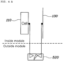
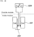
- FIGS. 4A and 4B illustrate a spark induction chamber of the battery system according to an embodiment of the present disclosure.
- FIG. 5 illustrates an insulation method of the battery system according to an embodiment of the present disclosure.
- a battery system may include: a battery module 100; a cooling channel 200 disposed adjacent to the battery module 100; a ground wire 300 configured to electrically connect the cooling channel 200 and a vehicle body 30; and a leakage current blocking device 500 configured to interrupt an electrical connection formed by the ground wire 300 when a leakage current occurs in the battery module 100.
- the battery module 100 includes a plurality of battery-cells 110 and a cooling fin 150 disposed between the plurality of battery cells 110 to cool the battery cells 110.
- the cooling fin 150 is a metal conductor and is in contact with the battery cells 110. In order to give a surface pressure between the battery cells 110 of the battery module 100, a side of the outermost battery cell 110 inside the module is pressed by a metal conductor.
- the cooling channel 200 is a metal conductor and may prevent static electricity in a state in which the cooling channel 200 is grounded with the vehicle body 30.
- a Thermal Interface Material (TIM) between the battery module 100 and the cooling channel 200 is a thermal conduction material, conducts heat between the battery module 100 and the cooling channel 200, and has insulation performance.
- the TIM is designed to be as thin as possible in order to improve the effectiveness of a water-cooled type battery system and reduce the cost price thereof.
- the leakage current blocking device 500 causes an electric spark to occur by the leakage current occurring in the battery module 100 and interrupts an electrical connection formed by the ground wire 300 on the basis of the number of times of the occurrence of the electric spark.
- the leakage current blocking device 500 draws a leakage current occurring at a point inside the battery module 100, which has insulation vulnerability, to the outside of the battery module 100 and causes an electric spark to occur, thereby discharging the leakage current.
- a spark induction chamber 520 of the leakage current blocking device 500 described below, has a gas filled therein.
- the spark induction chamber 520 operates a switch 540, described below, by using the expansion force of the volume of the gas, thereby blocking the ground wire 300.
- the leakage current blocking device 500 may include: the spark induction chamber 520 having an inner space, in which the electric spark occurs, and having a piston 524 which moves by the expansion of a gas in the inner space; a switch 540 configured to be operated by the piston 524; and a relay 560 configured to determine an electrical connection state of the ground wire 300 according to an operation of the switch 540.
- the spark induction chamber 520 has an inner space, in which a leakage current occurring in the battery module 100 can be discharged in the form of a spark, and the piston 524 which moves by the expansion of a gas filled in the inner space.
- the inner space is illustrated to have a tetragonal frame shape, but the inner space may have various shapes.
- the spark induction chamber 520 may have a gas filled therein, the volume of which increase by discharge energy.
- the piston 524 may protrude from the spark induction chamber 520 by an expansion force of the volume of a gas when the volume of the gas expands in a state in which a part of the piston 524 is inserted in the spark induction chamber 520.
- the spark induction chamber 520 may include, in the inner space thereof, a first acicular structure electrically connected to one point inside the battery module 100 and a second acicular structure connected to another point inside the battery module 100.
- the spark induction chamber 520 is a device which induces a leakage current occurring in the battery module 100 to the outside of the battery module 100 and causes a spark to occur.
- the spark induction chamber 520 may be connected to multiple points inside the battery module 100 but may be connected between the battery cells 110 and a module cover's inner surface 130, which are points having insulation vulnerability in a water-cooled type battery system, or between the battery cells 110 and the cooling fin 150.
- the first acicular structure may be connected to a battery cell 110 inside the battery module 100, and the second acicular structure may be connected to an inner surface 130 of a cover of the battery module 100.
- the first acicular structure may be connected to a battery cell 110 inside the 5 battery module 100 and the second acicular structure may be connected to a cooling fin 150 disposed between the battery cells 110 inside the battery module 100.
- the switch 540 when the switch 540 is pressed by the piston 524 of the spark induction chamber 520, the switch 540 operates a relay 560 electrically connected thereto.
- the relay 560 may be a B contact (normally ON) relay, and is disposed on the ground wire 300 for electrically connecting the cooling channel 200 and the vehicle body 30 and is turned on at the time of operation of the switch 540, so as to block the ground wire 300. Therefore, it is possible to ensure insulation performance even when a leakage current continuously occurs in the battery module 100 (conversely, when a leakage current does not continuously occur, there is an advantageous effect, such as the prevention of static electricity through the grounding of the cooling channel 200 to the vehicle body 30) .
- a temporary leakage current is discharged in the form of a spark inside the spark induction chamber 520, and, in relation to a continuous leakage current, a spark discharge inside the spark induction chamber 520 and the volume expansion of a gas by discharge energy may be used to block the ground wire 300 between the cooling channel 200 and the vehicle body 30, so that additional insulation safety can be ensured.
- a battery system may include: a battery module 100; a cooling channel 200 disposed adjacent to the battery module 100; a ground wire 300 configured to electrically connect the cooling channel 200 and a vehicle body 30; and a leakage current blocking device 500 disposed outside the battery module 100 and having a first acicular structure and a second acicular structure, which are electrically connected to two points inside the battery module 100, respectively, wherein a leakage current between the two points inside the battery module 100 is configured to cause an electric spark to occur between the first and second acicular structures.
- the leakage current blocking device 500 may further include: a spark induction chamber 520 having an inner space, in which the first and second acicular structures 522 are arranged, and having a piston 524 which moves as a gas in the inner space expands due to the occurrence of an electric spark between the first and second acicular structures 522; a switch 540 configured to be operated by the piston 524; and a relay 560 configured to determine an electrical connection state of the ground wire 300 according to the operation of the switch 540.
- the first acicular structure may be connected to a battery cell 110 inside the battery module 100 and the second acicular structure may be connected to an inner surface 130 of a cover of the battery module 100.
- the first acicular structure may be connected to battery cells 110 inside the battery module 100 and the second acicular structure may be connected to a cooling fin 150 disposed between the battery cells 110 inside the battery module 100.
- the battery system can induce a spark to occur outside a module when a leakage current flows in a structure of a water-cooled type battery system having insulation vulnerability, and can disconnect a ground wire between a cooling channel and a vehicle body when the leakage current continuously occurs, so that the battery system has an improved insulation safety.
- the battery system can prevent the occurrence of a spark inside the module, thereby preventing cell sealing release, explosion, and fire.
- the battery system can prevent the cooling channel and the vehicle body from being grounded, thereby improving insulation performance.
- the battery system can ensure insulation safety, thereby improving the merchantability of a vehicle.
Landscapes
- Engineering & Computer Science (AREA)
- Chemical & Material Sciences (AREA)
- Chemical Kinetics & Catalysis (AREA)
- Electrochemistry (AREA)
- General Chemical & Material Sciences (AREA)
- Manufacturing & Machinery (AREA)
- Sustainable Energy (AREA)
- Sustainable Development (AREA)
- Life Sciences & Earth Sciences (AREA)
- Power Engineering (AREA)
- Transportation (AREA)
- Mechanical Engineering (AREA)
- Microelectronics & Electronic Packaging (AREA)
- Battery Mounting, Suspending (AREA)
- Electric Propulsion And Braking For Vehicles (AREA)
- Connection Of Batteries Or Terminals (AREA)
- Liquid Crystal Substances (AREA)
Claims (3)
- Batteriesystem, umfassend:ein Batteriemodul (100);einen Kühlkanal (200), der neben dem Batteriemodul (100) angeordnet ist;einen Erdleiter (300), der konfiguriert ist, um den Kühlkanal (200) und eine Fahrzeugkarosserie elektrisch zu verbinden;dadurch gekennzeichnet, dassdas Batteriesystem ferner eine Kriechstrom-Blockierungsvorrichtung (500) umfasst, die konfiguriert ist, um eine elektrische Verbindung des Kühlkanals und der Fahrzeugkarosserie zu unterbrechen, wenn ein Kriechstrom in dem Batteriemodul vorkommt, wobei die Kriechstrom-Blockierungsvorrichtung (500) außerhalb des Batteriemoduls (100) angeordnet ist und eine erste nadelförmige Struktur und eine zweite nadelförmige Struktur aufweist, die jeweils mit zwei Punkten im Innern des Batteriemoduls (100) elektrisch verbunden sind,wobei die Kriechstrom-Blockierungsvorrichtung derart konfiguriert ist, dass ein Kriechstrom zwischen den zwei Punkten im Innern des Batteriemoduls bewirkt, dass ein elektrischer Funke zwischen den ersten und zweiten nadelförmigen Strukturen vorkommt, undwobei die Kriechstrom-Blockierungsvorrichtung weiter umfasst:eine Funkeninduktionskammer (520), die einen Innenraum aufweist, in dem die ersten und zweiten nadelförmigen Strukturen angeordnet sind, und einen Kolben (524) aufweist, der konfiguriert ist, um sich zu bewegen, wenn sich ein Gas in dem Innenraum auf Grund des Vorkommens eines elektrischen Funkens zwischen den ersten und zweiten nadelförmigen Strukturen ausdehnt;einen Schalter (540), der konfiguriert ist, um durch den Kolben (524) betätigt zu werden; undein Relais (560), das konfiguriert ist, um einen elektrischen Verbindungszustand des Erdleiters (300) gemäß der Betätigung des Schalters (540) zu bestimmen.
- Batteriesystem nach Anspruch 1, wobei die erste nadelförmige Struktur mit einer Batteriezelle im Innern des Batteriemoduls verbunden ist, und
wobei die zweite nadelförmige Struktur mit einer Innenfläche eines Deckels des Batteriemoduls verbunden ist. - Batteriesystem nach Anspruch 1, wobei die erste nadelförmige Struktur mit einer Batteriezelle im Innern des Batteriemoduls verbunden ist, und
wobei die zweite nadelförmige Struktur mit einer Kühlrippe verbunden ist, die zwischen Batteriezellen im Innern des Batteriemoduls angeordnet ist.
Applications Claiming Priority (2)
| Application Number | Priority Date | Filing Date | Title |
|---|---|---|---|
| KR1020170086415A KR102426109B1 (ko) | 2017-07-07 | 2017-07-07 | 배터리시스템 |
| EP17204345.7A EP3425695B1 (de) | 2017-07-07 | 2017-11-29 | Batteriesystem |
Related Parent Applications (2)
| Application Number | Title | Priority Date | Filing Date |
|---|---|---|---|
| EP17204345.7A Division-Into EP3425695B1 (de) | 2017-07-07 | 2017-11-29 | Batteriesystem |
| EP17204345.7A Division EP3425695B1 (de) | 2017-07-07 | 2017-11-29 | Batteriesystem |
Publications (2)
| Publication Number | Publication Date |
|---|---|
| EP3511997A1 EP3511997A1 (de) | 2019-07-17 |
| EP3511997B1 true EP3511997B1 (de) | 2020-07-22 |
Family
ID=60484285
Family Applications (2)
| Application Number | Title | Priority Date | Filing Date |
|---|---|---|---|
| EP19158244.4A Active EP3511997B1 (de) | 2017-07-07 | 2017-11-29 | Batteriesystem |
| EP17204345.7A Active EP3425695B1 (de) | 2017-07-07 | 2017-11-29 | Batteriesystem |
Family Applications After (1)
| Application Number | Title | Priority Date | Filing Date |
|---|---|---|---|
| EP17204345.7A Active EP3425695B1 (de) | 2017-07-07 | 2017-11-29 | Batteriesystem |
Country Status (4)
| Country | Link |
|---|---|
| US (1) | US10414284B2 (de) |
| EP (2) | EP3511997B1 (de) |
| KR (1) | KR102426109B1 (de) |
| CN (1) | CN109216799B (de) |
Families Citing this family (3)
| Publication number | Priority date | Publication date | Assignee | Title |
|---|---|---|---|---|
| CN111130065A (zh) * | 2019-12-31 | 2020-05-08 | 北京巨成科技有限公司 | 适用于储能系统的保护方法和装置 |
| KR20220084873A (ko) | 2020-12-14 | 2022-06-21 | 주식회사 이스퀘어 | 배터리시스템의 기술적 삼중보호정책에 의한 배터리 안정성 증대와 중장기적 거동분석 방법 |
| KR20220084874A (ko) | 2020-12-14 | 2022-06-21 | 주식회사 이스퀘어 | 배터리 관리 시스템의 핵심요소 이중제어를 통한 안전성 강화 방법 |
Family Cites Families (18)
| Publication number | Priority date | Publication date | Assignee | Title |
|---|---|---|---|---|
| JP2001037068A (ja) | 1999-07-16 | 2001-02-09 | Auto Network Gijutsu Kenkyusho:Kk | 車両の給電回路における漏電検知方法及び装置並びに漏電阻止方法及び装置 |
| NL1014558C2 (nl) | 2000-03-03 | 2001-09-13 | Skil Europ Bv | Boormachine met grendelmechanisme. |
| US6809579B2 (en) * | 2003-03-06 | 2004-10-26 | Hewlett-Packard Development Company, L.P. | Blocking mechanism to reduce leakage current |
| TW591976B (en) * | 2003-08-28 | 2004-06-11 | Zippy Tech Corp | Arc discharge protection device |
| KR100900089B1 (ko) * | 2007-04-13 | 2009-06-01 | 정태영 | 전기 선로에 스파크 발생시 자동 작동하는 전원 차단 장치 |
| KR100993080B1 (ko) | 2007-08-08 | 2010-11-08 | 주식회사 엘지화학 | 절연 캐패시터를 이용한 배터리 셀 전압 측정 장치 및 방법 |
| JP5334500B2 (ja) * | 2008-08-29 | 2013-11-06 | 三洋電機株式会社 | 車両用の電源装置 |
| JP2010218944A (ja) | 2009-03-18 | 2010-09-30 | Panasonic Corp | 鉛バッテリ用保安装置およびこれを一体に備えた鉛バッテリ |
| JP5979508B2 (ja) * | 2011-11-30 | 2016-08-24 | パナソニックIpマネジメント株式会社 | 電池パック |
| EP2973841B1 (de) * | 2013-03-14 | 2018-11-14 | Allison Transmission, Inc. | Flüssigkeitsbadgekühltes energiespeichersystem |
| EP2804251B1 (de) * | 2013-04-24 | 2016-07-20 | Samsung SDI Co., Ltd. | Fahrzeugbatteriesystem |
| KR101770327B1 (ko) | 2014-08-18 | 2017-08-22 | 주식회사 엘지화학 | 정전기 방전을 위한 보호회로 부재 및 이를 포함하는 전지팩 |
| KR101649552B1 (ko) * | 2014-10-28 | 2016-08-19 | 현대모비스 주식회사 | 과충전 방지장치가 장착된 배터리모듈 및 배터리모듈용 과충전 방지장치 |
| JP2016095929A (ja) * | 2014-11-12 | 2016-05-26 | トヨタ自動車株式会社 | 密閉型二次電池 |
| KR101608228B1 (ko) | 2014-11-20 | 2016-04-14 | 주식회사 아모텍 | 감전보호소자 및 이를 구비한 휴대용 전자장치 |
| KR20160069800A (ko) | 2014-12-09 | 2016-06-17 | 현대오트론 주식회사 | 배터리 관리 시스템의 누설 전류 검출 장치 및 방법 |
| GB2537431B (en) * | 2015-04-13 | 2018-01-03 | Tata Motors European Technical Ct Plc | Battery Module |
| CN205893404U (zh) * | 2016-08-11 | 2017-01-18 | 蓝星(北京)化工机械有限公司 | 一种电解槽往复式泄漏电流阻断装置 |
-
2017
- 2017-07-07 KR KR1020170086415A patent/KR102426109B1/ko active Active
- 2017-11-16 US US15/814,681 patent/US10414284B2/en not_active Expired - Fee Related
- 2017-11-29 EP EP19158244.4A patent/EP3511997B1/de active Active
- 2017-11-29 EP EP17204345.7A patent/EP3425695B1/de active Active
- 2017-12-05 CN CN201711269832.3A patent/CN109216799B/zh active Active
Non-Patent Citations (1)
| Title |
|---|
| None * |
Also Published As
| Publication number | Publication date |
|---|---|
| CN109216799B (zh) | 2023-04-14 |
| EP3425695B1 (de) | 2020-10-07 |
| US20190009687A1 (en) | 2019-01-10 |
| KR102426109B1 (ko) | 2022-07-28 |
| EP3425695A1 (de) | 2019-01-09 |
| KR20190005566A (ko) | 2019-01-16 |
| EP3511997A1 (de) | 2019-07-17 |
| US10414284B2 (en) | 2019-09-17 |
| CN109216799A (zh) | 2019-01-15 |
Similar Documents
| Publication | Publication Date | Title |
|---|---|---|
| US9184427B2 (en) | Battery assembly with high thermal conductivity | |
| CN101826611B (zh) | 可再充电电池及其模块 | |
| US10381633B2 (en) | Busbar | |
| EP2772963B1 (de) | Wiederaufladbare Batterie | |
| EP3511997B1 (de) | Batteriesystem | |
| EP3321993B1 (de) | Sekundärbatterie | |
| US10734630B2 (en) | Secondary battery with improved safety | |
| EP3989354A1 (de) | Batteriemodul mit sammelschienenplatte, batteriepack mit batteriemodul und elektronische vorrichtung | |
| KR101049820B1 (ko) | 이차 전지 | |
| CN108155429A (zh) | 过充安全保护装置 | |
| CN118056326A (zh) | 将排气通道和冷却通道集成的电池模块、包括该电池模块的电池组和制造该电池模块的方法 | |
| US20150288039A1 (en) | Battery module | |
| CN218586251U (zh) | 电池和用电设备 | |
| CN106450120A (zh) | 二次电池及电池模组 | |
| CN114171841B (zh) | 盖板组件、电池以及用电装置 | |
| US9627662B2 (en) | Secondary battery | |
| KR20210084147A (ko) | 냉각기능을 갖는 커넥터 | |
| CN218586256U (zh) | 防护组件、电池和用电设备 | |
| CN201622983U (zh) | 一种快速大电流保险装置 | |
| JP2013012478A (ja) | 車両用燃料電池モジュール | |
| CN119674420B (zh) | 电芯及电池包 | |
| CN221176088U (zh) | 接触器 | |
| CN221805798U (zh) | 一种软包电池模组热安全防护结构 | |
| KR20170012736A (ko) | 전기적 안전성이 우수한 이차전지용 캡조립체 및 그 이차전지 | |
| CN223858258U (zh) | 电芯盖板及电芯 |
Legal Events
| Date | Code | Title | Description |
|---|---|---|---|
| PUAI | Public reference made under article 153(3) epc to a published international application that has entered the european phase |
Free format text: ORIGINAL CODE: 0009012 |
|
| STAA | Information on the status of an ep patent application or granted ep patent |
Free format text: STATUS: THE APPLICATION HAS BEEN PUBLISHED |
|
| AC | Divisional application: reference to earlier application |
Ref document number: 3425695 Country of ref document: EP Kind code of ref document: P |
|
| AK | Designated contracting states |
Kind code of ref document: A1 Designated state(s): AL AT BE BG CH CY CZ DE DK EE ES FI FR GB GR HR HU IE IS IT LI LT LU LV MC MK MT NL NO PL PT RO RS SE SI SK SM TR |
|
| AX | Request for extension of the european patent |
Extension state: BA ME |
|
| STAA | Information on the status of an ep patent application or granted ep patent |
Free format text: STATUS: REQUEST FOR EXAMINATION WAS MADE |
|
| 17P | Request for examination filed |
Effective date: 20190809 |
|
| RBV | Designated contracting states (corrected) |
Designated state(s): AL AT BE BG CH CY CZ DE DK EE ES FI FR GB GR HR HU IE IS IT LI LT LU LV MC MK MT NL NO PL PT RO RS SE SI SK SM TR |
|
| GRAP | Despatch of communication of intention to grant a patent |
Free format text: ORIGINAL CODE: EPIDOSNIGR1 |
|
| STAA | Information on the status of an ep patent application or granted ep patent |
Free format text: STATUS: GRANT OF PATENT IS INTENDED |
|
| INTG | Intention to grant announced |
Effective date: 20200108 |
|
| GRAS | Grant fee paid |
Free format text: ORIGINAL CODE: EPIDOSNIGR3 |
|
| GRAA | (expected) grant |
Free format text: ORIGINAL CODE: 0009210 |
|
| STAA | Information on the status of an ep patent application or granted ep patent |
Free format text: STATUS: THE PATENT HAS BEEN GRANTED |
|
| AC | Divisional application: reference to earlier application |
Ref document number: 3425695 Country of ref document: EP Kind code of ref document: P |
|
| AK | Designated contracting states |
Kind code of ref document: B1 Designated state(s): AL AT BE BG CH CY CZ DE DK EE ES FI FR GB GR HR HU IE IS IT LI LT LU LV MC MK MT NL NO PL PT RO RS SE SI SK SM TR |
|
| REG | Reference to a national code |
Ref country code: GB Ref legal event code: FG4D |
|
| REG | Reference to a national code |
Ref country code: CH Ref legal event code: EP |
|
| REG | Reference to a national code |
Ref country code: DE Ref legal event code: R096 Ref document number: 602017020365 Country of ref document: DE |
|
| REG | Reference to a national code |
Ref country code: AT Ref legal event code: REF Ref document number: 1294236 Country of ref document: AT Kind code of ref document: T Effective date: 20200815 |
|
| REG | Reference to a national code |
Ref country code: IE Ref legal event code: FG4D |
|
| REG | Reference to a national code |
Ref country code: DE Ref legal event code: R079 Ref document number: 602017020365 Country of ref document: DE Free format text: PREVIOUS MAIN CLASS: H01M0002100000 Ipc: H01M0050200000 |
|
| REG | Reference to a national code |
Ref country code: LT Ref legal event code: MG4D |
|
| REG | Reference to a national code |
Ref country code: AT Ref legal event code: MK05 Ref document number: 1294236 Country of ref document: AT Kind code of ref document: T Effective date: 20200722 |
|
| PG25 | Lapsed in a contracting state [announced via postgrant information from national office to epo] |
Ref country code: GR Free format text: LAPSE BECAUSE OF FAILURE TO SUBMIT A TRANSLATION OF THE DESCRIPTION OR TO PAY THE FEE WITHIN THE PRESCRIBED TIME-LIMIT Effective date: 20201023 Ref country code: ES Free format text: LAPSE BECAUSE OF FAILURE TO SUBMIT A TRANSLATION OF THE DESCRIPTION OR TO PAY THE FEE WITHIN THE PRESCRIBED TIME-LIMIT Effective date: 20200722 Ref country code: SE Free format text: LAPSE BECAUSE OF FAILURE TO SUBMIT A TRANSLATION OF THE DESCRIPTION OR TO PAY THE FEE WITHIN THE PRESCRIBED TIME-LIMIT Effective date: 20200722 Ref country code: PT Free format text: LAPSE BECAUSE OF FAILURE TO SUBMIT A TRANSLATION OF THE DESCRIPTION OR TO PAY THE FEE WITHIN THE PRESCRIBED TIME-LIMIT Effective date: 20201123 Ref country code: BG Free format text: LAPSE BECAUSE OF FAILURE TO SUBMIT A TRANSLATION OF THE DESCRIPTION OR TO PAY THE FEE WITHIN THE PRESCRIBED TIME-LIMIT Effective date: 20201022 Ref country code: HR Free format text: LAPSE BECAUSE OF FAILURE TO SUBMIT A TRANSLATION OF THE DESCRIPTION OR TO PAY THE FEE WITHIN THE PRESCRIBED TIME-LIMIT Effective date: 20200722 Ref country code: LT Free format text: LAPSE BECAUSE OF FAILURE TO SUBMIT A TRANSLATION OF THE DESCRIPTION OR TO PAY THE FEE WITHIN THE PRESCRIBED TIME-LIMIT Effective date: 20200722 Ref country code: FI Free format text: LAPSE BECAUSE OF FAILURE TO SUBMIT A TRANSLATION OF THE DESCRIPTION OR TO PAY THE FEE WITHIN THE PRESCRIBED TIME-LIMIT Effective date: 20200722 Ref country code: AT Free format text: LAPSE BECAUSE OF FAILURE TO SUBMIT A TRANSLATION OF THE DESCRIPTION OR TO PAY THE FEE WITHIN THE PRESCRIBED TIME-LIMIT Effective date: 20200722 Ref country code: NO Free format text: LAPSE BECAUSE OF FAILURE TO SUBMIT A TRANSLATION OF THE DESCRIPTION OR TO PAY THE FEE WITHIN THE PRESCRIBED TIME-LIMIT Effective date: 20201022 |
|
| PGFP | Annual fee paid to national office [announced via postgrant information from national office to epo] |
Ref country code: DE Payment date: 20201028 Year of fee payment: 4 Ref country code: IT Payment date: 20201130 Year of fee payment: 4 Ref country code: FR Payment date: 20201112 Year of fee payment: 4 |
|
| PG25 | Lapsed in a contracting state [announced via postgrant information from national office to epo] |
Ref country code: RS Free format text: LAPSE BECAUSE OF FAILURE TO SUBMIT A TRANSLATION OF THE DESCRIPTION OR TO PAY THE FEE WITHIN THE PRESCRIBED TIME-LIMIT Effective date: 20200722 Ref country code: PL Free format text: LAPSE BECAUSE OF FAILURE TO SUBMIT A TRANSLATION OF THE DESCRIPTION OR TO PAY THE FEE WITHIN THE PRESCRIBED TIME-LIMIT Effective date: 20200722 Ref country code: LV Free format text: LAPSE BECAUSE OF FAILURE TO SUBMIT A TRANSLATION OF THE DESCRIPTION OR TO PAY THE FEE WITHIN THE PRESCRIBED TIME-LIMIT Effective date: 20200722 Ref country code: IS Free format text: LAPSE BECAUSE OF FAILURE TO SUBMIT A TRANSLATION OF THE DESCRIPTION OR TO PAY THE FEE WITHIN THE PRESCRIBED TIME-LIMIT Effective date: 20201122 |
|
| PG25 | Lapsed in a contracting state [announced via postgrant information from national office to epo] |
Ref country code: NL Free format text: LAPSE BECAUSE OF FAILURE TO SUBMIT A TRANSLATION OF THE DESCRIPTION OR TO PAY THE FEE WITHIN THE PRESCRIBED TIME-LIMIT Effective date: 20200722 |
|
| REG | Reference to a national code |
Ref country code: DE Ref legal event code: R097 Ref document number: 602017020365 Country of ref document: DE |
|
| PG25 | Lapsed in a contracting state [announced via postgrant information from national office to epo] |
Ref country code: SM Free format text: LAPSE BECAUSE OF FAILURE TO SUBMIT A TRANSLATION OF THE DESCRIPTION OR TO PAY THE FEE WITHIN THE PRESCRIBED TIME-LIMIT Effective date: 20200722 Ref country code: EE Free format text: LAPSE BECAUSE OF FAILURE TO SUBMIT A TRANSLATION OF THE DESCRIPTION OR TO PAY THE FEE WITHIN THE PRESCRIBED TIME-LIMIT Effective date: 20200722 Ref country code: CZ Free format text: LAPSE BECAUSE OF FAILURE TO SUBMIT A TRANSLATION OF THE DESCRIPTION OR TO PAY THE FEE WITHIN THE PRESCRIBED TIME-LIMIT Effective date: 20200722 Ref country code: DK Free format text: LAPSE BECAUSE OF FAILURE TO SUBMIT A TRANSLATION OF THE DESCRIPTION OR TO PAY THE FEE WITHIN THE PRESCRIBED TIME-LIMIT Effective date: 20200722 Ref country code: RO Free format text: LAPSE BECAUSE OF FAILURE TO SUBMIT A TRANSLATION OF THE DESCRIPTION OR TO PAY THE FEE WITHIN THE PRESCRIBED TIME-LIMIT Effective date: 20200722 |
|
| PLBE | No opposition filed within time limit |
Free format text: ORIGINAL CODE: 0009261 |
|
| STAA | Information on the status of an ep patent application or granted ep patent |
Free format text: STATUS: NO OPPOSITION FILED WITHIN TIME LIMIT |
|
| PG25 | Lapsed in a contracting state [announced via postgrant information from national office to epo] |
Ref country code: AL Free format text: LAPSE BECAUSE OF FAILURE TO SUBMIT A TRANSLATION OF THE DESCRIPTION OR TO PAY THE FEE WITHIN THE PRESCRIBED TIME-LIMIT Effective date: 20200722 |
|
| 26N | No opposition filed |
Effective date: 20210423 |
|
| PG25 | Lapsed in a contracting state [announced via postgrant information from national office to epo] |
Ref country code: SK Free format text: LAPSE BECAUSE OF FAILURE TO SUBMIT A TRANSLATION OF THE DESCRIPTION OR TO PAY THE FEE WITHIN THE PRESCRIBED TIME-LIMIT Effective date: 20200722 Ref country code: MC Free format text: LAPSE BECAUSE OF FAILURE TO SUBMIT A TRANSLATION OF THE DESCRIPTION OR TO PAY THE FEE WITHIN THE PRESCRIBED TIME-LIMIT Effective date: 20200722 |
|
| REG | Reference to a national code |
Ref country code: CH Ref legal event code: PL |
|
| PG25 | Lapsed in a contracting state [announced via postgrant information from national office to epo] |
Ref country code: LU Free format text: LAPSE BECAUSE OF NON-PAYMENT OF DUE FEES Effective date: 20201129 |
|
| REG | Reference to a national code |
Ref country code: BE Ref legal event code: MM Effective date: 20201130 |
|
| PG25 | Lapsed in a contracting state [announced via postgrant information from national office to epo] |
Ref country code: CH Free format text: LAPSE BECAUSE OF NON-PAYMENT OF DUE FEES Effective date: 20201130 Ref country code: LI Free format text: LAPSE BECAUSE OF NON-PAYMENT OF DUE FEES Effective date: 20201130 Ref country code: SI Free format text: LAPSE BECAUSE OF FAILURE TO SUBMIT A TRANSLATION OF THE DESCRIPTION OR TO PAY THE FEE WITHIN THE PRESCRIBED TIME-LIMIT Effective date: 20200722 |
|
| REG | Reference to a national code |
Ref country code: IE Ref legal event code: MM4A |
|
| REG | Reference to a national code |
Ref country code: NL Ref legal event code: MP Effective date: 20200722 |
|
| PG25 | Lapsed in a contracting state [announced via postgrant information from national office to epo] |
Ref country code: IE Free format text: LAPSE BECAUSE OF NON-PAYMENT OF DUE FEES Effective date: 20201129 |
|
| PG25 | Lapsed in a contracting state [announced via postgrant information from national office to epo] |
Ref country code: TR Free format text: LAPSE BECAUSE OF FAILURE TO SUBMIT A TRANSLATION OF THE DESCRIPTION OR TO PAY THE FEE WITHIN THE PRESCRIBED TIME-LIMIT Effective date: 20200722 Ref country code: MT Free format text: LAPSE BECAUSE OF FAILURE TO SUBMIT A TRANSLATION OF THE DESCRIPTION OR TO PAY THE FEE WITHIN THE PRESCRIBED TIME-LIMIT Effective date: 20200722 Ref country code: CY Free format text: LAPSE BECAUSE OF FAILURE TO SUBMIT A TRANSLATION OF THE DESCRIPTION OR TO PAY THE FEE WITHIN THE PRESCRIBED TIME-LIMIT Effective date: 20200722 |
|
| REG | Reference to a national code |
Ref country code: DE Ref legal event code: R119 Ref document number: 602017020365 Country of ref document: DE |
|
| PG25 | Lapsed in a contracting state [announced via postgrant information from national office to epo] |
Ref country code: MK Free format text: LAPSE BECAUSE OF FAILURE TO SUBMIT A TRANSLATION OF THE DESCRIPTION OR TO PAY THE FEE WITHIN THE PRESCRIBED TIME-LIMIT Effective date: 20200722 |
|
| GBPC | Gb: european patent ceased through non-payment of renewal fee |
Effective date: 20211129 |
|
| PG25 | Lapsed in a contracting state [announced via postgrant information from national office to epo] |
Ref country code: BE Free format text: LAPSE BECAUSE OF NON-PAYMENT OF DUE FEES Effective date: 20201130 |
|
| PG25 | Lapsed in a contracting state [announced via postgrant information from national office to epo] |
Ref country code: GB Free format text: LAPSE BECAUSE OF NON-PAYMENT OF DUE FEES Effective date: 20211129 Ref country code: DE Free format text: LAPSE BECAUSE OF NON-PAYMENT OF DUE FEES Effective date: 20220601 |
|
| PG25 | Lapsed in a contracting state [announced via postgrant information from national office to epo] |
Ref country code: FR Free format text: LAPSE BECAUSE OF NON-PAYMENT OF DUE FEES Effective date: 20211130 |
|
| PG25 | Lapsed in a contracting state [announced via postgrant information from national office to epo] |
Ref country code: IT Free format text: LAPSE BECAUSE OF NON-PAYMENT OF DUE FEES Effective date: 20211129 |