EP3511970A1 - Interrupteur électronique avec un détecteur pour fournir de l'information sur le déclenchement de l'interrupteur à un bus - Google Patents
Interrupteur électronique avec un détecteur pour fournir de l'information sur le déclenchement de l'interrupteur à un bus Download PDFInfo
- Publication number
- EP3511970A1 EP3511970A1 EP19150497.6A EP19150497A EP3511970A1 EP 3511970 A1 EP3511970 A1 EP 3511970A1 EP 19150497 A EP19150497 A EP 19150497A EP 3511970 A1 EP3511970 A1 EP 3511970A1
- Authority
- EP
- European Patent Office
- Prior art keywords
- unit
- detector
- switch
- measuring
- component
- Prior art date
- Legal status (The legal status is an assumption and is not a legal conclusion. Google has not performed a legal analysis and makes no representation as to the accuracy of the status listed.)
- Granted
Links
Images


Classifications
-
- H—ELECTRICITY
- H02—GENERATION; CONVERSION OR DISTRIBUTION OF ELECTRIC POWER
- H02H—EMERGENCY PROTECTIVE CIRCUIT ARRANGEMENTS
- H02H3/00—Emergency protective circuit arrangements for automatic disconnection directly responsive to an undesired change from normal electric working condition with or without subsequent reconnection ; integrated protection
- H02H3/26—Emergency protective circuit arrangements for automatic disconnection directly responsive to an undesired change from normal electric working condition with or without subsequent reconnection ; integrated protection responsive to difference between voltages or between currents; responsive to phase angle between voltages or between currents
- H02H3/32—Emergency protective circuit arrangements for automatic disconnection directly responsive to an undesired change from normal electric working condition with or without subsequent reconnection ; integrated protection responsive to difference between voltages or between currents; responsive to phase angle between voltages or between currents involving comparison of the voltage or current values at corresponding points in different conductors of a single system, e.g. of currents in go and return conductors
- H02H3/34—Emergency protective circuit arrangements for automatic disconnection directly responsive to an undesired change from normal electric working condition with or without subsequent reconnection ; integrated protection responsive to difference between voltages or between currents; responsive to phase angle between voltages or between currents involving comparison of the voltage or current values at corresponding points in different conductors of a single system, e.g. of currents in go and return conductors of a three-phase system
- H02H3/347—Emergency protective circuit arrangements for automatic disconnection directly responsive to an undesired change from normal electric working condition with or without subsequent reconnection ; integrated protection responsive to difference between voltages or between currents; responsive to phase angle between voltages or between currents involving comparison of the voltage or current values at corresponding points in different conductors of a single system, e.g. of currents in go and return conductors of a three-phase system using summation current transformers
-
- H—ELECTRICITY
- H01—ELECTRIC ELEMENTS
- H01H—ELECTRIC SWITCHES; RELAYS; SELECTORS; EMERGENCY PROTECTIVE DEVICES
- H01H83/00—Protective switches, e.g. circuit-breaking switches, or protective relays operated by abnormal electrical conditions otherwise than solely by excess current
- H01H83/14—Protective switches, e.g. circuit-breaking switches, or protective relays operated by abnormal electrical conditions otherwise than solely by excess current operated by imbalance of two or more currents or voltages, e.g. for differential protection
- H01H83/144—Protective switches, e.g. circuit-breaking switches, or protective relays operated by abnormal electrical conditions otherwise than solely by excess current operated by imbalance of two or more currents or voltages, e.g. for differential protection with differential transformer
-
- H—ELECTRICITY
- H01—ELECTRIC ELEMENTS
- H01H—ELECTRIC SWITCHES; RELAYS; SELECTORS; EMERGENCY PROTECTIVE DEVICES
- H01H83/00—Protective switches, e.g. circuit-breaking switches, or protective relays operated by abnormal electrical conditions otherwise than solely by excess current
- H01H83/20—Protective switches, e.g. circuit-breaking switches, or protective relays operated by abnormal electrical conditions otherwise than solely by excess current operated by excess current as well as by some other abnormal electrical condition
- H01H83/22—Protective switches, e.g. circuit-breaking switches, or protective relays operated by abnormal electrical conditions otherwise than solely by excess current operated by excess current as well as by some other abnormal electrical condition the other condition being imbalance of two or more currents or voltages
- H01H83/226—Protective switches, e.g. circuit-breaking switches, or protective relays operated by abnormal electrical conditions otherwise than solely by excess current operated by excess current as well as by some other abnormal electrical condition the other condition being imbalance of two or more currents or voltages with differential transformer
-
- H—ELECTRICITY
- H02—GENERATION; CONVERSION OR DISTRIBUTION OF ELECTRIC POWER
- H02H—EMERGENCY PROTECTIVE CIRCUIT ARRANGEMENTS
- H02H3/00—Emergency protective circuit arrangements for automatic disconnection directly responsive to an undesired change from normal electric working condition with or without subsequent reconnection ; integrated protection
- H02H3/02—Details
- H02H3/04—Details with warning or supervision in addition to disconnection, e.g. for indicating that protective apparatus has functioned
-
- H—ELECTRICITY
- H02—GENERATION; CONVERSION OR DISTRIBUTION OF ELECTRIC POWER
- H02H—EMERGENCY PROTECTIVE CIRCUIT ARRANGEMENTS
- H02H3/00—Emergency protective circuit arrangements for automatic disconnection directly responsive to an undesired change from normal electric working condition with or without subsequent reconnection ; integrated protection
- H02H3/26—Emergency protective circuit arrangements for automatic disconnection directly responsive to an undesired change from normal electric working condition with or without subsequent reconnection ; integrated protection responsive to difference between voltages or between currents; responsive to phase angle between voltages or between currents
- H02H3/32—Emergency protective circuit arrangements for automatic disconnection directly responsive to an undesired change from normal electric working condition with or without subsequent reconnection ; integrated protection responsive to difference between voltages or between currents; responsive to phase angle between voltages or between currents involving comparison of the voltage or current values at corresponding points in different conductors of a single system, e.g. of currents in go and return conductors
- H02H3/33—Emergency protective circuit arrangements for automatic disconnection directly responsive to an undesired change from normal electric working condition with or without subsequent reconnection ; integrated protection responsive to difference between voltages or between currents; responsive to phase angle between voltages or between currents involving comparison of the voltage or current values at corresponding points in different conductors of a single system, e.g. of currents in go and return conductors using summation current transformers
- H02H3/332—Emergency protective circuit arrangements for automatic disconnection directly responsive to an undesired change from normal electric working condition with or without subsequent reconnection ; integrated protection responsive to difference between voltages or between currents; responsive to phase angle between voltages or between currents involving comparison of the voltage or current values at corresponding points in different conductors of a single system, e.g. of currents in go and return conductors using summation current transformers with means responsive to DC component in the fault current
-
- H—ELECTRICITY
- H01—ELECTRIC ELEMENTS
- H01H—ELECTRIC SWITCHES; RELAYS; SELECTORS; EMERGENCY PROTECTIVE DEVICES
- H01H71/00—Details of the protective switches or relays covered by groups H01H73/00 - H01H83/00
- H01H71/04—Means for indicating condition of the switching device
- H01H2071/042—Means for indicating condition of the switching device with different indications for different conditions, e.g. contact position, overload, short circuit or earth leakage
Definitions
- the present invention relates to a switch, in particular an electronic release, comprising an electrical current sensing element arranged to inductively pick up an electric current flowing in an electrical current line that passes through the switch, which switch comprises a switch member. measurement connected to the sensing element and arranged to deliver a voltage corresponding to the electric current sensed by the sensing element, which switch comprises a trigger member connected to an output of the measuring member and arranged to activate a trigger mechanism. interruption of the electric current control line when the voltage delivered by the measuring device exceeds a predetermined threshold.
- Such a switch is known and is for example marketed under the reference CDA440C by the applicant.
- the sensing element inductively picks up electric current flowing in the electrical current line that passes through the switch.
- the measuring member delivers a voltage to the image of the current sensed.
- a mechanism for interrupting the electric current control line is activated in order to interrupt the electric current flowing in the electrical current line that passes through the 'light switch.
- the switch thus makes it possible to avoid problems caused by a differential type of electric fault current that would occur in the current line.
- the switch therefore operates as a protective device placed in the electric power line.
- the object of the invention is to provide a switch which makes it possible to supply information to a data bus without having to intervene directly on the operation of the measuring or triggering device.
- a switch is characterized in that the measuring member is connected to a detector arranged to detect the activation of the interruption mechanism by the trigger member and to produce a first status signal when activation of the interrupt mechanism by the triggering member has been detected, which detector is connected to a first input of a processing unit for providing the first status signal, which processing unit comprises a second input arranged to receive a second status signal indicative of a mechanical cut-off of the electrical power line, which processing unit is arranged to produce on the basis of received status signals a cut-off message of the current line and comprising the because of this cut.
- the presence of the detector makes it possible to detect the activation of the interruption mechanism by the triggering member, without having to intervene in the operation of the measuring or triggering member.
- the detector is connected to the measuring member, which itself is connected to the triggering member, it is the operation of the triggering member which is monitored without interference on the interruption mechanism or that of the triggering organ.
- the production of the first status signal by the detector makes it possible to supply this first status signal to the processing unit, which can also receive the second status signal indicating a mechanical break in the control line. Electric power.
- the processing unit can then produce a message breaking the current line and the cause of this cut. This latter message can then easily be provided to a data bus.
- a first preferred embodiment of a switch according to the invention is characterized in that the sensing element comprises a first element and the measuring element comprises a first unit, the first element being connected to the first unit, the first element being arranged to pick up an alternating differential component of the electric current, which first unit is arranged to deliver a voltage corresponding to the alternating differential component, which first unit comprises a first pole in electrical connection with the output of the measuring member and with a first input pin of a first component of the detector.
- a second preferred embodiment of an electronic switch according to the invention is characterized in that the sensing element comprises a second element and the measuring element comprises a second unit, the second element being connected to the second unit, the second element being arranged to capture a continuous differential component of the electric current, which second unit is arranged to deliver a voltage corresponding to the continuous differential component, which second unit comprises a second pole in electrical connection with the output of the measuring member and with a second input pin of a second component of the detector.
- a third preferred embodiment of an electronic switch according to the invention is characterized in that the first component of the detector is arranged to detect the activation of the interruption mechanism by the trigger member under control of the first unit of the measuring member and to produce the first status signal, which second component of the detector is arranged to detecting the activation of the interruption mechanism by the triggering member under the control of the second unit of the measuring member and producing a third state signal when the activation of the interruption mechanism by the triggering member has been detected by the second unit, which second component is connected to a third input of the processing unit to provide the third status signal therein.
- This makes it possible to notice a break in the line caused either by alternating current or by a continuous differential current.
- a fourth preferred embodiment of an electronic switch according to the invention is characterized in that the first and second components of the detector comprise a first and a second comparator respectively.
- the use of a comparator allows a simple and reliable realization of the detector.
- the processing unit is formed by an electrical energy management unit of a building.
- a capacitor is connected between the first and the second pole.
- the use of a capacitor provides a reliable and inexpensive embodiment of the switch according to the invention.
- a capacitor is connected between the first pole and a reference point.
- the capacitor can be connected to the output of the measuring device.
- the first pole is directly connected to a second output of the measuring member which itself is connected to the trigger member.
- FIG. figure 1 A first embodiment of a switch 1 according to the invention is illustrated in FIG. figure 1 .
- This switch is preferably formed by an electronic trigger.
- the switch is arranged to be placed on a line of electrical current 2 which passes through the switch.
- This electric current line 2 serves to supply electric current to a load 3.
- the line is for example formed of three phase conductors and a neutral conductor of the network. It will however be clear that the invention is not limited to a four-conductor line and also applies to other types of electric power lines.
- the switch comprises an interruption mechanism 4 intended to be placed on the current line 2 and arranged to interrupt the electric current flowing through this current line.
- interruption mechanism 4 intended to be placed on the current line 2 and arranged to interrupt the electric current flowing through this current line.
- the switch allows to cut the current on the line in case of presence on the line of a fault current.
- fault current is meant a differential current on the vector sum of the currents flowing in the active conductors of the current line.
- the switch also comprises an electrical current sensing element 5.
- the sensing element comprises a first element 5 which is arranged to inductively pick up an alternating differential component of the electric current flowing in line 2.
- This first element 5 of the sensing element is preferably made by a coil or a torus which will be placed around a section of the line 2.
- the measurement torus surrounds the active conductors and realizes the vector sum of the currents flowing in the line, putting thus highlighting a leakage current.
- a first unit 6 of a current measuring member 12 is connected to the first element 5 of the sensing element. This first unit 6 of the measuring device is arranged to deliver a voltage corresponding to the alternating differential component of the current sensed by the first element.
- the first unit receives the vector sum of the currents flowing in the line as supplied by the toroid and converts this sum into a voltage value.
- the vector sum In the ideal case, that is to say in the absence of fault current, the vector sum is equal to zero, and therefore the voltage corresponding to the sensed alternative differential component will also be equal to zero. In the presence of a fault current, the vector sum is not equal to zero, and therefore the voltage corresponding to the AC differential component of the sensed current will be different from zero.
- the switch also comprises a tripping member 13 connected to the measuring member and arranged to activate the interruption mechanism 4 of the electric current control line when the voltage value delivered by the first unit 6 of the organ of measurement passes a first predetermined threshold.
- the first unit 6 of the measuring member 12 has a first output pole 30, which is connected via a capacitor 9 to another output 31 of this first unit. This other output 31 is itself connected to a first input of the tripping member 13. A second input of the tripping member is directly connected to this first output pole 30.
- the tripping member 13 preferably comprises a control element 7 which controls the power supply of a relay 8, which itself controls the opening of the interruption mechanism 4.
- the first output pole 30 of the first unit 6 of the measuring member 12 is also connected to a first component 10 of a detector arranged to detect activation by the measuring member and the mechanism triggering member. 4 and produce a first state signal when the activation of the interrupt mechanism by the trigger member has been detected.
- the first component of the detector has an output which is connected to a first input 14 of a processing unit 11 to provide the first status signal.
- a second input 15 of the processing unit is arranged to receive a second status signal indicating a mechanical break in the electrical current line. This second state signal is for example produced by an element 16 which is connected to the interruption mechanism 4.
- the first component 10 of the detector is for example formed by a first comparator whose first pin is connected to the first pole 30 of the first unit of the measuring member 12.
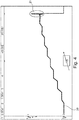
- the first element of the sensing member 5 When the electric current flows in the line of conduct 2, the first element of the sensing member 5 will capture the current flowing in this line and the current sensed will be transmitted to the first unit of the measuring member. If the current flows flawlessly in the line of conduct, the first measuring device will receive a vector sum of currents equal to zero. If there is a fault current present on the line, the vector sum of currents supplied by the first element will no longer be equal to zero and therefore the voltage delivered by the first unit will also not be zero. This voltage will be delivered to the first output pole 30 of the first unit 6 of the measuring member 12 and will therefore charge the capacitor 9, as illustrated by the line 20 to the figure 4 . This voltage will also be supplied to the second input of the tripping member 13.
- the capacitor 9 will thus charge. If the fault current continues to be present on line 2, the voltage at the first pole will continue to be delivered and charge the capacitor. The presence of the fault current will therefore have the consequence that the voltage supplied by the measuring member increases until the triggering member is activated. We then see a voltage peak 21 appear, as shown in FIG. figure 4 , indicating that the relay has tripped. Indeed, when the voltage delivered to the first output pole has crossed a first threshold, for example 4.2V, the capacitor will have a sufficient load to activate the trigger member. The capacitor will then discharge into the relay 8 which causes the trigger thereof. This results in a mechanical movement of the relay's pallet which by opening the magnetic circuit causes the peak voltage. This movement of the relay pallet will in turn release the interruption mechanism 4 and interrupt the circulation in the line of conduct 2.
- the first component 10 of the detector Since the first component 10 of the detector is connected to the first output pole 30 of the first unit 6 of the measuring device 12, it will also detect the voltage peak 21 which initiates the activation of the interruption mechanism 4. detection is for example carried out using as a detector a comparator which compares the voltage delivered to the first pole 30 to a detection threshold. The latter does not necessarily have the same value as the first threshold, which is a trigger threshold, and which is taken into account by the triggering member. Thus the first component of the detector will produce a first state signal indicating the activation of the interrupt mechanism 4. This first state signal will then be transmitted to the processing unit 11.
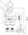
- the embodiment of the electronic switch illustrated in FIG. figure 2 differs from that of the figure 1 by the presence of a second unit 26 forming part of the measuring member 12, a second sensing member 25 and a second component 27 of the detector.
- the second sensing element 25 is placed on the electrical current control line 2 and is connected to the second unit 26 of the measuring element.
- the second element is arranged to capture a continuous differential component of the electric current flowing in the line of conduct 2.
- the second sensing element operates according to the principle of the magnetic saturation of the torus which carries out the induction pickup, as described in FIG. European patent 2,870,670 .
- the torus is formed by two windings on a magnetic core.
- the first winding receives an excitation current and thus induces a flux in the second winding.
- the amplitude of the signal thus sensed by the second winding varies as a function of the magnetic saturation level of the core caused by the DC component of the differential current flowing in the current line. This amplitude variation then makes it possible to determine the continuous differential component of the electric current flowing in the line of conduct of current 2.
- the invention is of course not limited to the embodiment making use of a torus with two windings.
- the second unit 26 is arranged to deliver a voltage corresponding to the continuous differential component sensed by the second sensing element 25.
- a second pole of the second unit is connected to an input of the second component 27 of the detector.
- the capacitor 9 is connected between the first pole 30 of the first unit 6 and the second pole 28 of the second unit 26.
- the second component 27 has an output connected to a third input 17 of the processing unit 11.
- the first pole of the first unit of the measuring member is connected to the first component of the detector and the second pole of the second unit of the measuring member is connected to the third input of the processing unit, this The latter will be able to see if the status signal comes from the first or second unit of the measuring device and therefore whether the current interruption is due to an AC or DC differential current component.
- the switch according to the invention could also be formed by the embodiment taken from the figure 2 but without the first unit 6 and without the first component of the detector.
- this embodiment there is also no capacitor 9 because the detection of a continuous type fault current uses a power supply not shown in the figure. It is therefore not necessary to store energy to trigger the relay.
- Providing the status signals to the processing unit will enable the processing unit to recognize the cause of the triggering of the interrupt mechanism. So when the processing unit is going to receive substantially simultaneously the first status signal at its first input and the third status signal at its second input it will deduce that the interrupt mechanism has been activated by the trigger member. More particularly, it will be able to detect that it is a fault current that caused the trip. If, on the other hand, the second and third status signals are supplied to the processing unit, the processing unit will assume that it is a continuous differential fault current that caused the trip. On the other hand, if only the second status signal is received, the processing unit will deduce that it is not a fault current that caused the trip, but a human intervention.
- the figure 3 still illustrates a third embodiment of a switch according to the invention.
- This embodiment differs from that of the figure 2 by the connection between the measuring member 6, 26, the trigger member 13 and the detector 10, 27.
- the first 6, respectively the second 26, measuring member comprises a third 31, respectively a fourth 33, pole of exit.
- the capacitor 9 is connected between the first and third output pole of the first measuring member.
- the third output pole of the first measuring member is connected to a reference point 32.
- the fourth pole of the second measuring member is connected to another reference point 34, which may be the same as the reference point 32.
- the triggering element is connected to yet another reference point 35, which may be the same as the reference point 32.
- the first and the second output pole of the first and second measuring members are, on the one hand, connected to another comparator 34, which is part of the tripping member 13, and on the other hand to a fourth 18, respectively a fifth 19, input of the processing unit 11.
- This other comparator 35 is arranged to detect the crossing of the first, respectively of the second threshold by the voltage delivered by the first, respectively the second, measuring member. When this other comparator detects that the first and / or second threshold has been crossed, it communicates this information to the relay control 8 so as to cause the activation of the interruption mechanism 4.
- the activation of the relay 8 will also be provided to the first, respectively the second detector, and the fourth, respectively fifth, input of the processing unit 11. The latter will then find that a signal is present on the first and fourth, respectively the third and the fifth input and will thus be able to determine the status signal.
- the triggering of the relay 8 will be detected by the detectors 10 and / or 27.
- the processing unit 11 then goes according to the state of the signals present on these inputs 14, 15, 17, 18 and 19 to be able to constitute a signal state.
Landscapes
- Engineering & Computer Science (AREA)
- Power Engineering (AREA)
- Measurement Of Current Or Voltage (AREA)
- Emergency Protection Circuit Devices (AREA)
Abstract
Description
- La présente invention concerne un interrupteur, en particulier un déclencheur électronique, comprenant un organe de captage de courant électrique agencé pour capter par induction un courant électrique circulant dans une ligne de conduite de courant électrique qui traverse l'interrupteur, lequel interrupteur comprend un organe de mesure relié à l'organe de captage et agencé pour délivrer une tension correspondante au courant électrique capté par l'organe de captage, lequel interrupteur comprend un organe de déclenchement relié à une sortie de l'organe de mesure et agencé pour activer un mécanisme d'interruption de la ligne de conduite de courant électrique lorsque la tension délivrée par l'organe de mesure franchit un seuil prédéterminé.
- Un tel interrupteur est connu et est par exemple commercialisé sous la référence CDA440C par la demanderesse. L'organe de captage capte par induction du courant électrique circulant dans la ligne de conduite de courant électrique qui traverse l'interrupteur. L'organe de mesure délivre une tension à l'image du courant capté. Lorsque la tension délivrée par l'organe de mesure franchit un seuil prédéterminé, un mécanisme d'interruption de la ligne de conduite de courant électrique est activé afin d'interrompre le courant électrique qui circule dans la ligne de conduite de courant électrique qui traverse l'interrupteur. L'interrupteur permet ainsi d'éviter des problèmes causés par un courant électrique de défaut de type différentiel qui se produirait dans la ligne de conduite de courant. L'interrupteur opère donc comme un dispositif de protection placé dans la ligne de courant électrique.
- De nos jours les immeubles sont de plus en plus équipés d'un bus domestique permettant de fournir des données à divers endroits dans l'immeuble. D'autre part il y a un intérêt croissant pour collecter des données relatives aux fonctionnements d'appareils électriques afin entre autres d'améliorer leur fiabilité et d'anticiper des problèmes de fonctionnement. Toutefois une liaison entre un interrupteur, en particulier un déclencheur électronique, et un bus sur lequel des données peuvent circuler peut poser un problème, car il faut prélever les données au niveau de l'organe de mesure ou de l'organe de déclenchent. Une telle intervention risque de perturber le fonctionnement de l'organe de mesure ou de l'organe de déclenchent et d'affecter ainsi la sécurité.
- L'invention a pour but de réaliser un interrupteur qui permet de fournir de l'information à un bus de données sans pour autant devoir intervenir directement sur le fonctionnement de l'organe de mesure ou de déclenchement.
- A cette fin un interrupteur suivant l'invention est caractérisé en ce que l'organe de mesure est relié à un détecteur agencé pour détecter l'activation du mécanisme d'interruption par l'organe de déclenchement et produire un premier signal d'état lorsque l'activation du mécanisme d'interruption par l'organe de déclenchement a été détectée, lequel détecteur est relié à une première entrée d'une unité de traitement pour y fournir le premier signal d'état, laquelle unité de traitement comprend une deuxième entrée agencée pour recevoir un deuxième signal d'état indiquant une coupure mécanique de la ligne de conduite de courant électrique, laquelle unité de traitement est agencée pour produire sur base de signaux d'état reçus un message de coupure de la ligne de courant et comprenant la cause de cette coupure. La présence du détecteur permet de détecter l'activation du mécanisme d'interruption par l'organe de déclenchement, et cela sans devoir intervenir sur le fonctionnement de l'organe de mesure ou de déclenchement. En effet comme le détecteur est relié à l'organe de mesure, qui lui-même est relié à l'organe de déclenchement, c'est le fonctionnement de l'organe de déclenchement qui est surveillé sans interférence sur le mécanisme d'interruption ou celui de l'organe de déclenchement. La production du premier signal d'état par le détecteur permet de fournir ce premier signal d'état à l'unité de traitement qui peut aussi recevoir le deuxième signal d'état indiquant une coupure mécanique de la ligne de conduite de courant électrique. Sur base de ces signaux d'état l'unité de traitement peut alors produire un message de coupure de la ligne de courant et de la cause de cette coupure. Ce dernier message peut alors facilement être fourni à un bus de données.
- Une première forme de réalisation préférentielle d'un interrupteur suivant l'invention est caractérisée en ce que l'organe de captage comprend un premier élément et l'organe de mesure comprend une première unité, le premier élément étant relié à la première unité, le premier élément étant agencé pour capter une composante différentielle alternative du courant électrique, laquelle première unité étant agencée pour délivrer une tension correspondante à la composante différentielle alternative, laquelle première unité comporte un premier pôle en liaison électrique avec la sortie de l'organe de mesure et avec une première broche d'entrée d'un premier composant du détecteur. Cela permet de constater que l'interruption de courant a été causée par une composante différentielle alternative du courant électrique circulant dans la ligne.
- Une deuxième forme de réalisation préférentielle d'un interrupteur électronique suivant l'invention est caractérisée en ce que l'organe de captage comprend un deuxième élément et l'organe de mesure comprend une deuxième unité, le deuxième élément étant relié à la deuxième unité, le deuxième élément étant agencé pour capter une composante différentielle continue du courant électrique, laquelle deuxième unité étant agencée pour délivrer une tension correspondante à la composante différentielle continue, laquelle deuxième unité comporte un deuxième pôle en liaison électrique avec la sortie de l'organe de mesure et avec une deuxième broche d'entrée d'un deuxième composant du détecteur. Cela permet de constater que l'interruption de courant a été causée par une composante différentielle continue du courant électrique circulant dans la ligne.
- Une troisième forme de réalisation préférentielle d'un interrupteur électronique suivant l'invention est caractérisée en ce que le premier composant du détecteur est agencé pour détecter l'activation du mécanisme d'interruption par l'organe de déclenchement sous contrôle de la première unité de l'organe de mesure et produire le premier signal d'état, lequel deuxième composant du détecteur est agencé pour détecter l'activation du mécanisme d'interruption par l'organe de déclenchement sous contrôle de la deuxième unité de l'organe de mesure et produire un troisième signal d'état lorsque l'activation du mécanisme d'interruption par l'organe de déclenchement a été détectée par la deuxième unité, lequel deuxième composant est relié à une troisième entrée de l'unité de traitement pour y fournir le troisième signal d'état. Ceci permet de constater une coupure de la ligne causée soit par courant différentiel alternatif, soit par un courant différentiel continu.
- Une quatrième forme de réalisation préférentielle d'un interrupteur électronique suivant l'invention est caractérisée en ce que le premier, respectivement le deuxième, composant du détecteur comporte un premier, respectivement un deuxième, comparateur. L'usage d'un comparateur permet une réalisation simple et fiable du détecteur.
- Selon une variante de l'invention et de ses formes de réalisation préférentielles, l'unité de traitement est formée par une unité de gestion d'énergie électrique d'un bâtiment.
- Selon une possibilité des deuxième, troisième et quatrième formes de réalisation préférentielles, un condensateur est branché entre le premier et le deuxième pôle. L'usage d'un condensateur offre une réalisation fiable et peu onéreuse de l'interrupteur selon l'invention.
- Selon une possibilité des première, deuxième, troisième et quatrième formes de réalisation préférentielles, un condensateur est branché entre le premier pôle et un point de référence.
- Selon une spécificité de ces possibilités, le condensateur peut être relié à la sortie de l'organe de mesure.
- De préférence, selon ces possibilités et cette spécificité, le premier pôle est directement relié à une deuxième sortie de l'organe de mesure qui elle-même est reliée à l'organe de déclenchement.
- L'invention sera maintenant décrite plus en détails à l'aide des dessins qui illustrent des formes de réalisation préférentielle d'un interrupteur selon l'invention. Dans les dessins :
- La
figure 1 illustre une première forme de réalisation d'un interrupteur selon l'invention ; - La
figure 2 illustre une deuxième forme de réalisation d'un interrupteur selon l'invention ; - La
figure 3 illustre une troisième forme de réalisation d'un interrupteur selon l'invention ; et - La
figure 4 illustre l'évolution dans le temps de la tension électrique présente sur la connexion entre l'organe de mesure et l'organe de déclenchement. - Dans les dessins une même référence a été attribuée à un même élément ou à un élément analogue.
- Une première forme de réalisation d'un interrupteur 1 selon l'invention est illustrée à la
figure 1 . Cet interrupteur est de préférence formé par un déclencheur électronique. L'interrupteur est agencé pour être placé sur une ligne de conduite de courant électrique 2 qui traverse l'interrupteur. Cette ligne de courant électrique 2 sert à alimenter en courant électrique une charge 3. La ligne est par exemple formée de trois conducteurs de phase et d'un conducteur de neutre du réseau. Il sera toutefois clair que l'invention n'est pas limitée à une ligne à quatre conducteurs et s'applique aussi à d'autres types de lignes de courant électrique. - L'interrupteur comporte un mécanisme d'interruption 4 destiné à être placé sur la ligne de conduite de courant 2 et agencé pour interrompre le courant électrique qui circule à travers cette ligne de courant. Ainsi l'interrupteur permet de couper le courant sur la ligne en cas de présence sur la ligne d'un courant de défaut. Par courant de défaut on entend un courant différentiel sur la somme vectorielle des courants circulants dans les conducteurs actifs de la ligne de courant.
- L'interrupteur comporte également un organe de captage de courant électrique 5. De préférence l'organe de captage comporte un premier élément 5 qui est agencé pour capter par induction une composante différentielle alternative du courant électrique circulant dans la ligne 2. Ce premier élément 5 de l'organe de captage est de préférence réalisé par une bobine ou un tore qui sera placé autour d'une section de la ligne 2. Le tore de mesure entoure les conducteurs actifs et réalise la somme vectorielle des courants circulant dans la ligne, mettant ainsi en évidence un courant de fuite. Une première unité 6 d'un organe 12 de mesure de courant est reliée au premier élément 5 de l'organe de captage. Cette première unité 6 de l'organe de mesure est agencée pour délivrer une tension correspondante à la composante différentielle alternative du courant captée par le premier élément. A cette fin la première unité reçoit la somme vectorielle des courants circulant dans la ligne telle que fournie par le tore et convertit cette somme en une valeur de tension. Dans le cas idéal, c'est-à-dire en absence de courant de défaut, la somme vectorielle est égale à zéro, et donc la tension correspondante à la composante différentielle alternative captée sera également égale à zéro. En présence de courant de défaut, la somme vectorielle n'est pas égale à zéro, et donc la tension correspondante à la composante différentielle alternative du courant captée sera différente de zéro.
- L'interrupteur comprend également un organe de déclenchement 13 relié à l'organe de mesure et agencé pour activer le mécanisme d'interruption 4 de la ligne de conduite de courant électrique lorsque la valeur de tension délivrée par la première unité 6 de l'organe de mesure franchit un premier seuil prédéterminé. La première unité 6 de l'organe de mesure 12 comporte un premier pôle de sortie 30, qui est relié via un condensateur 9 à une autre sortie 31 de cette première unité. Cette autre sortie 31 est elle-même reliée à une première entrée de l'organe de déclenchement 13. Une deuxième entrée de l'organe de déclenchement est directement reliée à ce premier pôle de sortie 30.
- L'organe de déclenchement 13 comporte de préférence un élément de commande 7 qui commande l'alimentation en énergie d'un relais 8, qui lui-même commande l'ouverture du mécanisme d'interruption 4.
- Le premier pôle de sortie 30 de la première unité 6 de l'organe de mesure 12 est également reliée à un premier composant 10 d'un détecteur agencé pour détecter l'activation par l'organe de mesure et l'organe de déclenchement du mécanisme d'interruption 4 et produire un premier signal d'état lorsque l'activation du mécanisme d'interruption par l'organe de déclenchement a été détectée. Le premier composant du détecteur comporte une sortie qui est relié à une première entrée 14 d'une unité de traitement 11 pour y fournir le premier signal d'état. Une deuxième entrée 15 de l'unité de traitement est agencée pour recevoir un deuxième signal d'état indiquant une coupure mécanique de la ligne de conduite de courant électrique. Ce deuxième signal d'état est par exemple produit par un élément 16 qui est en liaison avec le mécanisme d'interruption 4. Le premier composant 10 du détecteur est par exemple formé par un premier comparateur dont une première broche est reliée au premier pôle 30 de la première unité de l'organe de mesure 12.
- Lorsque le courant électrique circule dans la ligne de conduite 2, le premier élément de l'organe de captage 5 va capter du courant circulant dans cette ligne et ce courant capté sera transmis à la première unité de l'organe de mesure. Si le courant circule sans défaut dans la ligne de conduite, le premier organe de mesure recevra une somme vectorielle des courants égale à zéro. S'il y a un courant de défaut présent sur la ligne, la somme vectorielle des courants fournie par le premier élément ne sera plus égale à zéro et donc la tension délivrée par la première unité ne sera également pas égale à zéro. Cette tension sera délivrée au premier pôle 30 de sortie de la première unité 6 de l'organe de mesure 12 et va donc charger le condensateur 9, comme illustré par la ligne 20 à la
figure 4 . Cette tension sera également fournie à la deuxième entrée de l'organe de déclenchement 13. - Le condensateur 9 va ainsi se charger. Si le courant de défaut continue à être présent sur la ligne de conduite 2, la tension au premier pôle continuera à être délivré et à charger le condensateur. La présence du courant de défaut va donc avoir pour conséquence que la tension fournie par l'organe de mesure augmente jusqu'à activer l'organe de déclenchement. On voit alors un pic de tension 21 apparaître, comme illustré à la
figure 4 , indiquant que le relais a déclenché. En effet, lorsque la tension délivrée au premier pôle de sortie aura franchi un premier seuil, par exemple de 4,2V, le condensateur aura une charge suffisante pour activer l'organe de déclenchement. Le condensateur va alors se décharger dans le relais 8 ce qui provoque le déclenchement de celui-ci. Cela se traduit par un mouvement mécanique de la palette du relais qui en ouvrant le circuit magnétique provoque le pic de tension. Ce mouvement de la palette du relais va à son tour libérer le mécanisme d'interruption 4 et interrompre la circulation dans la ligne de conduite 2. - Puisque le premier composant 10 du détecteur est relié au premier pôle 30 de sortie de la première unité 6 de l'organe de mesure 12, il va également détecter le pic de tension 21 qui initialise l'activation du mécanisme d'interruption 4. Cette détection est par exemple réalisée en utilisant en tant que détecteur un comparateur qui compare la tension délivrée au premier pôle 30 à un seuil de détection. Ce dernier n'a pas nécessairement la même valeur que le premier seuil, qui est un seuil de déclenchement, et qui est pris en considération par l'organe de déclenchement. Ainsi le premier composant du détecteur va produire un premier signal d'état indiquant l'activation du mécanisme d'interruption 4. Ce premier signal d'état va alors être transmis à l'unité de traitement 11 qui pourra ainsi produire, sur base de ce signal d'état reçu, un message de coupure de la ligne de courant et indiquant que la cause de cette coupure est due à la présence d'un courant de défaut ayant une composante alternative sur la ligne de conduite de courant. L'unité de traitement va alors remettre ce message au bus domestique auquel elle est reliée.
- La forme de réalisation de l'interrupteur électronique illustrée à la
figure 2 se distingue de celle de lafigure 1 par la présence d'une deuxième unité 26 faisant partie de l'organe de mesure 12, d'un deuxième organe de captage 25 et d'un deuxième composant 27 du détecteur. Le deuxième organe de captage 25 est placé sur la ligne de conduite de courant électrique 2 et est relié à la deuxième unité 26 de l'organe de mesure. Le deuxième élément étant agencé pour capter une composante différentielle continue du courant électrique circulant dans la ligne de conduite 2. De préférence le deuxième organe de captage fonctionne selon le principe de la saturation magnétique du tore qui réalise le captage par induction, comme décrit dans le brevet Européen2 870 670 . Dans cette dernière forme de réalisation le tore est formé par deux enroulements sur un noyau magnétique. Le premier enroulement reçoit un courant d'excitation et induit ainsi un flux dans le deuxième enroulement. L'amplitude du signal ainsi captée par le deuxième enroulement varie en fonction du niveau de saturation magnétique du tore provoquée par la composante continu du courant différentiel qui circule dans la ligne de conduite de courant. Cette variation d'amplitude permet alors de déterminer la composante différentielle continue du courant électrique circulant dans la ligne de conduite 2 de courant. L'invention n'est bien entendu pas limitée à la forme de réalisation faisant usage d'un tore à deux enroulements. - La deuxième unité 26 est agencée pour délivrer une tension correspondante à la composante différentielle continue captée par le deuxième organe 25 de captage. Un deuxième pôle de la deuxième unité est relié à une entrée du deuxième composant 27 du détecteur. Le condensateur 9 est branché entre le premier pôle 30 de la première unité 6 et le deuxième pôle 28 de la deuxième unité 26. Le deuxième composant 27 possède une sortie reliée à une troisième entrée 17 de l'unité de traitement 11. Lorsque la deuxième unité recevra une composante différentielle continue captée par le deuxième organe de captage qui est différent de zéro, c'est-à-dire un niveau de saturation magnétique du tore qui est différent de zéro, la deuxième unité va délivrer une tension correspondante à cette composante différentielle continue. Si cette tension franchit un deuxième seuil prédéterminé, de par exemple 2,2V, elle va provoquer le déclenchement du mécanisme d'interruption. Le deuxième composant du détecteur va également recevoir cette information qu'un déclenchement a eu lieu et va ainsi produire un troisième signal d'état.
- Puisque le premier pôle de la première unité de l'organe de mesure est relié au premier composant du détecteur et que le deuxième pôle de la deuxième unité de l'organe de mesure est relié à la troisième entrée de l'unité de traitement, cette dernière sera en mesure de constater si le signal de statut provient de la première ou de la deuxième unité de l'organe de mesure et donc si l'interruption de courant est due à un composant de courant différentiel alternatif ou continu.
- Bien entendu il sera clair que l'interrupteur suivant l'invention pourrait aussi être formé par la forme de réalisation reprise à la
figure 2 mais sans la première unité 6 et sans le premier composant du détecteur. Dans cette forme de réalisation il n'y a également pas de condensateur 9 car la détection d'un courant de défaut de type continu utilise une alimentation non représentée sur la figure. Il n'est donc pas nécessaire d'emmagasiner de l'énergie pour déclencher le relais. - La fourniture des signaux d'état à l'unité de traitement va permettre à cette dernière de reconnaître la cause du déclenchement du mécanisme d'interruption. Ainsi lorsque l'unité de traitement va recevoir pratiquement simultanément le premier signal d'état à sa première entrée et le troisième signal d'état à sa deuxième entrée elle en déduira que le mécanisme d'interruption a été activé par l'organe de déclenchement. Plus particulièrement elle sera en mesure de détecter que c'est un courant de défaut qui a provoqué le déclenchement. Si par contre ce sont les deuxième et troisième signaux d'état qui sont fournis à l'unité de traitement, cette dernière en déduira que c'est un courant de défaut différentiel continu qui a provoqué le déclenchement. Par contre si seul le deuxième signal d'état est reçu, l'unité de traitement en déduira que ce n'est pas un courant de défaut qui a provoqué le déclenchement, mais une intervention humaine.
- La
figure 3 illustre encore une troisième forme de réalisation d'un interrupteur suivant l'invention. Cette forme de réalisation se distingue de celle de lafigure 2 par la connexion entre l'organe de mesure 6, 26, l'organe de déclenchement 13 et le détecteur 10, 27. Le premier 6, respectivement le deuxième 26, organe de mesure comporte un troisième 31, respectivement un quatrième 33, pôle de sortie. Le condensateur 9 est branché entre le premier et le troisième pôle de sortie du premier organe de mesure. Le troisième pôle de sortie du premier organe de mesure est relié à un point de référence 32. Le quatrième pôle du deuxième organe de mesure est relié à un autre point de référence 34, qui le cas échéant peut être le même que le point de référence 32. L'organe de déclenchement est relié à encore un autre point de référence 35, qui le cas échéant peut être le même que le point de référence 32. - Le premier, respectivement le deuxième, pôle de sortie du premier, respectivement du deuxième, organe de mesure sont d'une part reliés à un autre comparateur 34, qui fait partie de l'organe de déclenchement 13, et d'autre part à une quatrième 18, respectivement une cinquième 19, entrée de l'unité de traitement 11. Cet autre comparateur 35 est agencé pour détecter le franchissement du premier, respectivement du deuxième, seuil par la tension délivré par le premier, respectivement le deuxième, organe de mesure. Lorsque cet autre comparateur détecte que le premier et/ou le deuxième seuil est franchi, il communique cette information à la commande de relais 8 pour ainsi provoquer l'activation du mécanisme d'interruption 4.
- L'activation du relais 8 sera également fournie au premier, respectivement au deuxième détecteur, ainsi qu'à la quatrième, respectivement une cinquième, entrée de l'unité de traitement 11. Cette dernière va alors constater qu'un signal est présent sur la première et la quatrième, respectivement la troisième et la cinquième entrée et va ainsi être en mesure de déterminer le signal d'état.
- Le déclenchement du relais 8 sera détecté par les détecteurs 10 et/ou 27. L'unité de traitement 11 va alors selon l'état des signaux présents sur ces entrées 14, 15, 17, 18 et 19 être en mesure de constituer un signal d'état.
Claims (11)
- Interrupteur (1), en particulier un déclencheur électronique, comprenant un organe de captage (5, 25) de courant électrique agencé pour capter par induction un courant électriquecirculant dans une ligne de conduite de courant électrique (2) qui traverse l'interrupteur (1), lequel interrupteur (1) comprend un organe de mesure (12) relié à l'organe de captage (5, 25) et agencé pour délivrer une tension correspondante au courant électrique capté par l'organe de captage (5, 25), lequel interrupteur (1) comprend un organe de déclenchement (13) relié à une sortie de l'organe de mesure (12) et agencé pour activer un mécanisme d'interruption (4) de la ligne de conduite de courant électrique (2) lorsque la tension délivrée par l'organe de mesure (12) franchit un seuil prédéterminé, caractérisé en ce que l'organe de mesure (12) est reliée à un détecteur agencé pour détecter l'activation du mécanisme d'interruption (4) par l'organe de déclenchement (13) et produire un premier signal d'état lorsque l'activation du mécanisme d'interruption (4) par l'organe de déclenchement (13) a été détectée, lequel détecteur est relié à une première entrée (14) d'une unité de traitement (11) pour y fournir le premier signal d'état, laquelle unité de traitement (11) comprend une deuxième entrée (15) agencée pour recevoir un deuxième signal d'état indiquant une coupure mécanique de la ligne de conduite de courant électrique (2), laquelle unité de traitement (11) est agencée pour produire sur base de signaux d'état reçus un message de coupure de la ligne de courant (2) et comprenant la cause de cette coupure.
- Interrupteur suivant la revendication 1, caractérisé en ce que l'organe de captage comprend un premier élément (5) et l'organe de mesure (12) comprend une première unité (6), le premier élément (5) étant relié à la première unité (6), le premier élément (5) étant agencé pour capter une composante différentielle alternative du courant électrique, laquelle première unité (6) étant agencée pour délivrer une tension correspondante à la composante différentielle alternative captée, laquelle première unité (6) comporte un premier pôle (30) en liaison électrique avec la sortie de l'organe de mesure (12) et avec une première broche d'entrée d'un premier composant (10) du détecteur.
- Interrupteur suivant la revendication 1 ou 2, caractérisé en ce que l'organe de captage comprend un deuxième élément (25) et l'organe de mesure (12) comprend une deuxième unité (26), le deuxième élément (25) étant relié à la deuxième unité (26), le deuxième élément (25) étant agencé pour capter une composante différentielle continue du courant électrique, laquelle deuxième unité (26) étant agencée pour délivrer une tension correspondante à la composante différentielle continue, laquelle deuxième unité (26) comporte un deuxième pôle (28) en liaison électrique avec la sortie de l'organe de mesure (12) et avec une deuxième broche d'entrée d'un deuxième composant (27) du détecteur.
- Interrupteur suivant les revendications 2 et 3, caractérisé en ce que le premier composant (10) du détecteur est agencé pour détecter l'activation du mécanisme d'interruption (4) par l'organe de déclenchement (13) sous contrôle de la première unité (6) de l'organe de mesure (12) et produire le premier signal d'état, lequel deuxième composant (27) du détecteur est agencé pour détecter l'activation du mécanisme d'interruption (4) par l'organe de déclenchement (13) sous contrôle de la deuxième unité (26) de l'organe de mesure (12) et produire un troisième signal d'état lorsque l'activation du mécanisme d'interruption (4) par l'organe de déclenchement (13) a été détectée par la deuxième unité (26), lequel deuxième composant (27) est relié à une troisième entrée (17) de l'unité de traitement (11) pour y fournir le troisième signal d'état.
- Interrupteur suivant la revendication 2 respectivement 3, caractérisé en ce que le premier (10), respectivement le deuxième (27), composant du détecteur comporte un premier, respectivement un deuxième, comparateur.
- Interrupteur suivant l'une des revendications 1 à 5, caractérisé en ce que l'unité de traitement est formée par une unité de gestion d'énergie électrique d'un bâtiment.
- Interrupteur suivant l'une des revendications 3 à 5, caractérisé en ce qu'un condensateur (9) est branché entre le premier (30) et le deuxième (28) pôle.
- Interrupteur suivant l'une des revendications 2 à 5, caractérisé en ce qu'un condensateur (9) est branché entre le premier pôle (30) et un point de référence (32).
- Interrupteur suivant la revendication 7 ou 8, caractérisé en ce que le condensateur (9) est relié à la sortie de l'organe de mesure (12).
- Interrupteur suivant la revendication 7, 8 ou 9, caractérisé en ce que le premier pôle (30) est directement relié à une deuxième sortie de l'organe de mesure (12) qui elle-même est reliée à l'organe de déclenchement (13).
- Interrupteur suivant la revendication 3 ou 4, caractérisé en ce que le premier (30), respectivement le deuxième (28), pôle de sortie du premier (6), respectivement du deuxième (26), organe de mesure (12) sont reliés à un autre comparateur (34), qui fait partie de l'organe de déclenchement (13), lequel autre comparateur (34) est agencé pour détecter le franchissement d'un premier, respectivement d'un deuxième, seuil par la tension délivré par le premier, respectivement le deuxième (26), organe de mesure (12), lequel autre comparateur (34) est également agencé et pour provoquer l'activation du mécanisme d'interruption (4) après détection que le premier et/ou le deuxième seuil a été franchi.
Applications Claiming Priority (1)
| Application Number | Priority Date | Filing Date | Title |
|---|---|---|---|
| FR1850131A FR3076623B1 (fr) | 2018-01-08 | 2018-01-08 | Interrupteur electronique |
Publications (2)
| Publication Number | Publication Date |
|---|---|
| EP3511970A1 true EP3511970A1 (fr) | 2019-07-17 |
| EP3511970B1 EP3511970B1 (fr) | 2021-12-15 |
Family
ID=63014610
Family Applications (1)
| Application Number | Title | Priority Date | Filing Date |
|---|---|---|---|
| EP19150497.6A Active EP3511970B1 (fr) | 2018-01-08 | 2019-01-07 | Interrupteur électronique avec un détecteur pour fournir de l'information sur le déclenchement de l'interrupteur à un bus |
Country Status (2)
| Country | Link |
|---|---|
| EP (1) | EP3511970B1 (fr) |
| FR (1) | FR3076623B1 (fr) |
Citations (5)
| Publication number | Priority date | Publication date | Assignee | Title |
|---|---|---|---|---|
| DE19743900A1 (de) * | 1997-10-04 | 1999-04-08 | Metrawatt Gmbh Gossen | Fehlerstromschutzschalter sowie Meßverfahren zur Durchführung in einem Fehlerstromschutzschalter |
| EP2870670A1 (fr) | 2012-07-05 | 2015-05-13 | Hager-Electro SAS | Dispositif de protection différentiel. |
| EP3223381A1 (fr) * | 2016-03-14 | 2017-09-27 | Rosemount Aerospace Inc. | Circuit de détection de mise à la terre ou à la masse d'un element chauffant dans un circuit à courant alternatif |
| FR3050081A1 (fr) * | 2016-04-12 | 2017-10-13 | Schneider Electric Ind Sas | Dispositif de detection d'un courant de defaut |
| EP3242369A1 (fr) * | 2016-04-28 | 2017-11-08 | LSIS Co., Ltd. | Circuit de commande de déclenchement pour un disjoncteur pour détecter ac et/ou dc |
-
2018
- 2018-01-08 FR FR1850131A patent/FR3076623B1/fr active Active
-
2019
- 2019-01-07 EP EP19150497.6A patent/EP3511970B1/fr active Active
Patent Citations (5)
| Publication number | Priority date | Publication date | Assignee | Title |
|---|---|---|---|---|
| DE19743900A1 (de) * | 1997-10-04 | 1999-04-08 | Metrawatt Gmbh Gossen | Fehlerstromschutzschalter sowie Meßverfahren zur Durchführung in einem Fehlerstromschutzschalter |
| EP2870670A1 (fr) | 2012-07-05 | 2015-05-13 | Hager-Electro SAS | Dispositif de protection différentiel. |
| EP3223381A1 (fr) * | 2016-03-14 | 2017-09-27 | Rosemount Aerospace Inc. | Circuit de détection de mise à la terre ou à la masse d'un element chauffant dans un circuit à courant alternatif |
| FR3050081A1 (fr) * | 2016-04-12 | 2017-10-13 | Schneider Electric Ind Sas | Dispositif de detection d'un courant de defaut |
| EP3242369A1 (fr) * | 2016-04-28 | 2017-11-08 | LSIS Co., Ltd. | Circuit de commande de déclenchement pour un disjoncteur pour détecter ac et/ou dc |
Also Published As
| Publication number | Publication date |
|---|---|
| FR3076623A1 (fr) | 2019-07-12 |
| FR3076623B1 (fr) | 2020-09-18 |
| EP3511970B1 (fr) | 2021-12-15 |
Similar Documents
| Publication | Publication Date | Title |
|---|---|---|
| EP0815630B2 (fr) | Appareil electrique de protection differentielle a circuit test | |
| EP1466336B1 (fr) | Procede pour determiner l'usure des contacts d'un appareil interrupteur | |
| FR2807580A1 (fr) | Circuit de detection de defaillance electrique avec alimentation de mode double | |
| JP5884826B2 (ja) | 故障表示及び二次電源を備える回路遮断器 | |
| CA2649183A1 (fr) | Dispositif a courant residuel a modes de fonctionnement dependant ou independant de la tension | |
| WO2019110711A1 (fr) | Procede de detection de l'etat d'un appareil de protection electrique dans une installation electrique et dispositif de detection mettant en oeuvre ledit procede | |
| RU2304338C1 (ru) | Способ контроля отключения и неуспешного автоматического повторного включения секционирующего выключателя в линии кольцевой сети | |
| EP2648010A1 (fr) | Procédé de gestion des alarmes en fonction des courants de défaut dans une installation électrique et dispositif de mise en oeuvre dudit procédé | |
| FR2974684A1 (fr) | Systeme de protection et de supervision d'un circuit de distribution d'energie electrique a courant continu | |
| EP3511970B1 (fr) | Interrupteur électronique avec un détecteur pour fournir de l'information sur le déclenchement de l'interrupteur à un bus | |
| FR2643195A1 (fr) | Procede et dispositif de protection d'un circuit ou reseau electrique a l'aide d'un disjoncteur a courant differentiel | |
| EP0524300A1 (fr) | Dispositif de protection pour appareils, machines et installations electriques | |
| EP0180506B1 (fr) | Dispositif de sécurité pour appareil de protection différentielle | |
| EP3776617B1 (fr) | Dispositif électronique de coupure et procédé de détection de défaut | |
| EP2626881B1 (fr) | Procédé et dispositif de sécurité électrique par fuite à la terre | |
| EP3259815A1 (fr) | Systeme de protection selective d'un reseau electrique et procede de protection associe | |
| EP2693585B1 (fr) | Système de protection d'une pluralité de départs électriques contre des courts-circuits, et installation électrique comprenant un tel système de protection | |
| WO2020240097A1 (fr) | Appareil de protection de ligne (l) electrique pour détecter un défaut de fuite, de court-circuit, de surintensité et d'arc | |
| EP3583618B1 (fr) | Disjoncteur | |
| FR2709867A1 (fr) | Procédé et dispositif de réenclenchement d'un disjoncteur. | |
| EP3764496A1 (fr) | Procédé permettant, à partir d'un appareil de protection, d'indiquer au moins une information de défaut relative à au moins un défaut détecté dans une ligne électrique, un tel appareil de protection et installation électrique comprenant au moins un tel appareil de protection | |
| FR2640441A1 (fr) | Protection electronique preventive contre les risques d'electrocutions dus aux mises a la masse des circuits electriques | |
| CN103155326B (zh) | 具有故障指示和辅供电器的电子断路器 | |
| EP4075471A1 (fr) | Module auxiliaire de protection électrique, appareil de protection électrique comportant un tel module, et procédé de fonctionnement associé | |
| BE1010688A7 (fr) | Interrupteur differentiel. |
Legal Events
| Date | Code | Title | Description |
|---|---|---|---|
| PUAI | Public reference made under article 153(3) epc to a published international application that has entered the european phase |
Free format text: ORIGINAL CODE: 0009012 |
|
| STAA | Information on the status of an ep patent application or granted ep patent |
Free format text: STATUS: THE APPLICATION HAS BEEN PUBLISHED |
|
| AK | Designated contracting states |
Kind code of ref document: A1 Designated state(s): AL AT BE BG CH CY CZ DE DK EE ES FI FR GB GR HR HU IE IS IT LI LT LU LV MC MK MT NL NO PL PT RO RS SE SI SK SM TR |
|
| AX | Request for extension of the european patent |
Extension state: BA ME |
|
| STAA | Information on the status of an ep patent application or granted ep patent |
Free format text: STATUS: REQUEST FOR EXAMINATION WAS MADE |
|
| 17P | Request for examination filed |
Effective date: 20200116 |
|
| RBV | Designated contracting states (corrected) |
Designated state(s): AL AT BE BG CH CY CZ DE DK EE ES FI FR GB GR HR HU IE IS IT LI LT LU LV MC MK MT NL NO PL PT RO RS SE SI SK SM TR |
|
| STAA | Information on the status of an ep patent application or granted ep patent |
Free format text: STATUS: EXAMINATION IS IN PROGRESS |
|
| 17Q | First examination report despatched |
Effective date: 20201209 |
|
| REG | Reference to a national code |
Ref country code: DE Ref legal event code: R079 Ref document number: 602019009973 Country of ref document: DE Free format text: PREVIOUS MAIN CLASS: H01H0083140000 Ipc: G01R0031000000 |
|
| GRAP | Despatch of communication of intention to grant a patent |
Free format text: ORIGINAL CODE: EPIDOSNIGR1 |
|
| STAA | Information on the status of an ep patent application or granted ep patent |
Free format text: STATUS: GRANT OF PATENT IS INTENDED |
|
| RIC1 | Information provided on ipc code assigned before grant |
Ipc: G01R 31/00 20060101AFI20210414BHEP Ipc: H02H 3/33 20060101ALI20210414BHEP Ipc: H02H 3/347 20060101ALI20210414BHEP Ipc: H01H 83/14 20060101ALI20210414BHEP Ipc: H01H 83/22 20060101ALI20210414BHEP Ipc: H01H 71/04 20060101ALI20210414BHEP Ipc: H02H 3/04 20060101ALI20210414BHEP |
|
| INTG | Intention to grant announced |
Effective date: 20210429 |
|
| GRAJ | Information related to disapproval of communication of intention to grant by the applicant or resumption of examination proceedings by the epo deleted |
Free format text: ORIGINAL CODE: EPIDOSDIGR1 |
|
| STAA | Information on the status of an ep patent application or granted ep patent |
Free format text: STATUS: EXAMINATION IS IN PROGRESS |
|
| INTC | Intention to grant announced (deleted) | ||
| GRAS | Grant fee paid |
Free format text: ORIGINAL CODE: EPIDOSNIGR3 |
|
| STAA | Information on the status of an ep patent application or granted ep patent |
Free format text: STATUS: GRANT OF PATENT IS INTENDED |
|
| GRAP | Despatch of communication of intention to grant a patent |
Free format text: ORIGINAL CODE: EPIDOSNIGR1 |
|
| INTG | Intention to grant announced |
Effective date: 20211001 |
|
| GRAA | (expected) grant |
Free format text: ORIGINAL CODE: 0009210 |
|
| STAA | Information on the status of an ep patent application or granted ep patent |
Free format text: STATUS: THE PATENT HAS BEEN GRANTED |
|
| AK | Designated contracting states |
Kind code of ref document: B1 Designated state(s): AL AT BE BG CH CY CZ DE DK EE ES FI FR GB GR HR HU IE IS IT LI LT LU LV MC MK MT NL NO PL PT RO RS SE SI SK SM TR |
|
| REG | Reference to a national code |
Ref country code: GB Ref legal event code: FG4D Free format text: NOT ENGLISH Ref country code: CH Ref legal event code: EP |
|
| REG | Reference to a national code |
Ref country code: IE Ref legal event code: FG4D Free format text: LANGUAGE OF EP DOCUMENT: FRENCH Ref country code: DE Ref legal event code: R096 Ref document number: 602019009973 Country of ref document: DE |
|
| REG | Reference to a national code |
Ref country code: AT Ref legal event code: REF Ref document number: 1455884 Country of ref document: AT Kind code of ref document: T Effective date: 20220115 |
|
| REG | Reference to a national code |
Ref country code: LT Ref legal event code: MG9D |
|
| REG | Reference to a national code |
Ref country code: NL Ref legal event code: MP Effective date: 20211215 |
|
| PG25 | Lapsed in a contracting state [announced via postgrant information from national office to epo] |
Ref country code: RS Free format text: LAPSE BECAUSE OF FAILURE TO SUBMIT A TRANSLATION OF THE DESCRIPTION OR TO PAY THE FEE WITHIN THE PRESCRIBED TIME-LIMIT Effective date: 20211215 Ref country code: LT Free format text: LAPSE BECAUSE OF FAILURE TO SUBMIT A TRANSLATION OF THE DESCRIPTION OR TO PAY THE FEE WITHIN THE PRESCRIBED TIME-LIMIT Effective date: 20211215 Ref country code: FI Free format text: LAPSE BECAUSE OF FAILURE TO SUBMIT A TRANSLATION OF THE DESCRIPTION OR TO PAY THE FEE WITHIN THE PRESCRIBED TIME-LIMIT Effective date: 20211215 Ref country code: BG Free format text: LAPSE BECAUSE OF FAILURE TO SUBMIT A TRANSLATION OF THE DESCRIPTION OR TO PAY THE FEE WITHIN THE PRESCRIBED TIME-LIMIT Effective date: 20220315 |
|
| REG | Reference to a national code |
Ref country code: AT Ref legal event code: MK05 Ref document number: 1455884 Country of ref document: AT Kind code of ref document: T Effective date: 20211215 |
|
| PG25 | Lapsed in a contracting state [announced via postgrant information from national office to epo] |
Ref country code: SE Free format text: LAPSE BECAUSE OF FAILURE TO SUBMIT A TRANSLATION OF THE DESCRIPTION OR TO PAY THE FEE WITHIN THE PRESCRIBED TIME-LIMIT Effective date: 20211215 Ref country code: NO Free format text: LAPSE BECAUSE OF FAILURE TO SUBMIT A TRANSLATION OF THE DESCRIPTION OR TO PAY THE FEE WITHIN THE PRESCRIBED TIME-LIMIT Effective date: 20220315 Ref country code: LV Free format text: LAPSE BECAUSE OF FAILURE TO SUBMIT A TRANSLATION OF THE DESCRIPTION OR TO PAY THE FEE WITHIN THE PRESCRIBED TIME-LIMIT Effective date: 20211215 Ref country code: HR Free format text: LAPSE BECAUSE OF FAILURE TO SUBMIT A TRANSLATION OF THE DESCRIPTION OR TO PAY THE FEE WITHIN THE PRESCRIBED TIME-LIMIT Effective date: 20211215 Ref country code: GR Free format text: LAPSE BECAUSE OF FAILURE TO SUBMIT A TRANSLATION OF THE DESCRIPTION OR TO PAY THE FEE WITHIN THE PRESCRIBED TIME-LIMIT Effective date: 20220316 |
|
| PG25 | Lapsed in a contracting state [announced via postgrant information from national office to epo] |
Ref country code: NL Free format text: LAPSE BECAUSE OF FAILURE TO SUBMIT A TRANSLATION OF THE DESCRIPTION OR TO PAY THE FEE WITHIN THE PRESCRIBED TIME-LIMIT Effective date: 20211215 |
|
| PG25 | Lapsed in a contracting state [announced via postgrant information from national office to epo] |
Ref country code: SM Free format text: LAPSE BECAUSE OF FAILURE TO SUBMIT A TRANSLATION OF THE DESCRIPTION OR TO PAY THE FEE WITHIN THE PRESCRIBED TIME-LIMIT Effective date: 20211215 Ref country code: SK Free format text: LAPSE BECAUSE OF FAILURE TO SUBMIT A TRANSLATION OF THE DESCRIPTION OR TO PAY THE FEE WITHIN THE PRESCRIBED TIME-LIMIT Effective date: 20211215 Ref country code: RO Free format text: LAPSE BECAUSE OF FAILURE TO SUBMIT A TRANSLATION OF THE DESCRIPTION OR TO PAY THE FEE WITHIN THE PRESCRIBED TIME-LIMIT Effective date: 20211215 Ref country code: PT Free format text: LAPSE BECAUSE OF FAILURE TO SUBMIT A TRANSLATION OF THE DESCRIPTION OR TO PAY THE FEE WITHIN THE PRESCRIBED TIME-LIMIT Effective date: 20220418 Ref country code: ES Free format text: LAPSE BECAUSE OF FAILURE TO SUBMIT A TRANSLATION OF THE DESCRIPTION OR TO PAY THE FEE WITHIN THE PRESCRIBED TIME-LIMIT Effective date: 20211215 Ref country code: EE Free format text: LAPSE BECAUSE OF FAILURE TO SUBMIT A TRANSLATION OF THE DESCRIPTION OR TO PAY THE FEE WITHIN THE PRESCRIBED TIME-LIMIT Effective date: 20211215 Ref country code: CZ Free format text: LAPSE BECAUSE OF FAILURE TO SUBMIT A TRANSLATION OF THE DESCRIPTION OR TO PAY THE FEE WITHIN THE PRESCRIBED TIME-LIMIT Effective date: 20211215 |
|
| PG25 | Lapsed in a contracting state [announced via postgrant information from national office to epo] |
Ref country code: PL Free format text: LAPSE BECAUSE OF FAILURE TO SUBMIT A TRANSLATION OF THE DESCRIPTION OR TO PAY THE FEE WITHIN THE PRESCRIBED TIME-LIMIT Effective date: 20211215 Ref country code: AT Free format text: LAPSE BECAUSE OF FAILURE TO SUBMIT A TRANSLATION OF THE DESCRIPTION OR TO PAY THE FEE WITHIN THE PRESCRIBED TIME-LIMIT Effective date: 20211215 |
|
| REG | Reference to a national code |
Ref country code: DE Ref legal event code: R097 Ref document number: 602019009973 Country of ref document: DE |
|
| PG25 | Lapsed in a contracting state [announced via postgrant information from national office to epo] |
Ref country code: MC Free format text: LAPSE BECAUSE OF FAILURE TO SUBMIT A TRANSLATION OF THE DESCRIPTION OR TO PAY THE FEE WITHIN THE PRESCRIBED TIME-LIMIT Effective date: 20211215 Ref country code: IS Free format text: LAPSE BECAUSE OF FAILURE TO SUBMIT A TRANSLATION OF THE DESCRIPTION OR TO PAY THE FEE WITHIN THE PRESCRIBED TIME-LIMIT Effective date: 20220415 |
|
| REG | Reference to a national code |
Ref country code: BE Ref legal event code: MM Effective date: 20220131 |
|
| PLBE | No opposition filed within time limit |
Free format text: ORIGINAL CODE: 0009261 |
|
| STAA | Information on the status of an ep patent application or granted ep patent |
Free format text: STATUS: NO OPPOSITION FILED WITHIN TIME LIMIT |
|
| PG25 | Lapsed in a contracting state [announced via postgrant information from national office to epo] |
Ref country code: LU Free format text: LAPSE BECAUSE OF NON-PAYMENT OF DUE FEES Effective date: 20220107 Ref country code: DK Free format text: LAPSE BECAUSE OF FAILURE TO SUBMIT A TRANSLATION OF THE DESCRIPTION OR TO PAY THE FEE WITHIN THE PRESCRIBED TIME-LIMIT Effective date: 20211215 Ref country code: AL Free format text: LAPSE BECAUSE OF FAILURE TO SUBMIT A TRANSLATION OF THE DESCRIPTION OR TO PAY THE FEE WITHIN THE PRESCRIBED TIME-LIMIT Effective date: 20211215 |
|
| 26N | No opposition filed |
Effective date: 20220916 |
|
| PG25 | Lapsed in a contracting state [announced via postgrant information from national office to epo] |
Ref country code: SI Free format text: LAPSE BECAUSE OF FAILURE TO SUBMIT A TRANSLATION OF THE DESCRIPTION OR TO PAY THE FEE WITHIN THE PRESCRIBED TIME-LIMIT Effective date: 20211215 Ref country code: BE Free format text: LAPSE BECAUSE OF NON-PAYMENT OF DUE FEES Effective date: 20220131 |
|
| PG25 | Lapsed in a contracting state [announced via postgrant information from national office to epo] |
Ref country code: IE Free format text: LAPSE BECAUSE OF NON-PAYMENT OF DUE FEES Effective date: 20220107 |
|
| PG25 | Lapsed in a contracting state [announced via postgrant information from national office to epo] |
Ref country code: IT Free format text: LAPSE BECAUSE OF FAILURE TO SUBMIT A TRANSLATION OF THE DESCRIPTION OR TO PAY THE FEE WITHIN THE PRESCRIBED TIME-LIMIT Effective date: 20211215 |
|
| P01 | Opt-out of the competence of the unified patent court (upc) registered |
Effective date: 20230606 |
|
| GBPC | Gb: european patent ceased through non-payment of renewal fee |
Effective date: 20230107 |
|
| PG25 | Lapsed in a contracting state [announced via postgrant information from national office to epo] |
Ref country code: GB Free format text: LAPSE BECAUSE OF NON-PAYMENT OF DUE FEES Effective date: 20230107 |
|
| PG25 | Lapsed in a contracting state [announced via postgrant information from national office to epo] |
Ref country code: MK Free format text: LAPSE BECAUSE OF FAILURE TO SUBMIT A TRANSLATION OF THE DESCRIPTION OR TO PAY THE FEE WITHIN THE PRESCRIBED TIME-LIMIT Effective date: 20211215 Ref country code: CY Free format text: LAPSE BECAUSE OF FAILURE TO SUBMIT A TRANSLATION OF THE DESCRIPTION OR TO PAY THE FEE WITHIN THE PRESCRIBED TIME-LIMIT Effective date: 20211215 |
|
| PG25 | Lapsed in a contracting state [announced via postgrant information from national office to epo] |
Ref country code: HU Free format text: LAPSE BECAUSE OF FAILURE TO SUBMIT A TRANSLATION OF THE DESCRIPTION OR TO PAY THE FEE WITHIN THE PRESCRIBED TIME-LIMIT; INVALID AB INITIO Effective date: 20190107 |
|
| PG25 | Lapsed in a contracting state [announced via postgrant information from national office to epo] |
Ref country code: MT Free format text: LAPSE BECAUSE OF FAILURE TO SUBMIT A TRANSLATION OF THE DESCRIPTION OR TO PAY THE FEE WITHIN THE PRESCRIBED TIME-LIMIT Effective date: 20211215 |
|
| PG25 | Lapsed in a contracting state [announced via postgrant information from national office to epo] |
Ref country code: TR Free format text: LAPSE BECAUSE OF FAILURE TO SUBMIT A TRANSLATION OF THE DESCRIPTION OR TO PAY THE FEE WITHIN THE PRESCRIBED TIME-LIMIT Effective date: 20211215 |
|
| REG | Reference to a national code |
Ref country code: CH Ref legal event code: U11 Free format text: ST27 STATUS EVENT CODE: U-0-0-U10-U11 (AS PROVIDED BY THE NATIONAL OFFICE) Effective date: 20260201 |
|
| PGFP | Annual fee paid to national office [announced via postgrant information from national office to epo] |
Ref country code: DE Payment date: 20260128 Year of fee payment: 8 |
|
| PGFP | Annual fee paid to national office [announced via postgrant information from national office to epo] |
Ref country code: FR Payment date: 20260126 Year of fee payment: 8 |
|
| PGFP | Annual fee paid to national office [announced via postgrant information from national office to epo] |
Ref country code: CH Payment date: 20260201 Year of fee payment: 8 |