EP3511961A1 - Transformer for vehicles - Google Patents
Transformer for vehicles Download PDFInfo
- Publication number
- EP3511961A1 EP3511961A1 EP16915745.0A EP16915745A EP3511961A1 EP 3511961 A1 EP3511961 A1 EP 3511961A1 EP 16915745 A EP16915745 A EP 16915745A EP 3511961 A1 EP3511961 A1 EP 3511961A1
- Authority
- EP
- European Patent Office
- Prior art keywords
- cooling pipes
- tank
- vehicle
- transformer
- vehicular
- Prior art date
- Legal status (The legal status is an assumption and is not a legal conclusion. Google has not performed a legal analysis and makes no representation as to the accuracy of the status listed.)
- Granted
Links
Images




Classifications
-
- H—ELECTRICITY
- H01—ELECTRIC ELEMENTS
- H01F—MAGNETS; INDUCTANCES; TRANSFORMERS; SELECTION OF MATERIALS FOR THEIR MAGNETIC PROPERTIES
- H01F27/00—Details of transformers or inductances, in general
- H01F27/08—Cooling; Ventilating
- H01F27/10—Liquid cooling
- H01F27/12—Oil cooling
-
- H—ELECTRICITY
- H01—ELECTRIC ELEMENTS
- H01F—MAGNETS; INDUCTANCES; TRANSFORMERS; SELECTION OF MATERIALS FOR THEIR MAGNETIC PROPERTIES
- H01F27/00—Details of transformers or inductances, in general
- H01F27/08—Cooling; Ventilating
- H01F27/10—Liquid cooling
- H01F27/12—Oil cooling
- H01F27/14—Expansion chambers; Oil conservators; Gas cushions; Arrangements for purifying, drying, or filling
-
- H—ELECTRICITY
- H01—ELECTRIC ELEMENTS
- H01F—MAGNETS; INDUCTANCES; TRANSFORMERS; SELECTION OF MATERIALS FOR THEIR MAGNETIC PROPERTIES
- H01F27/00—Details of transformers or inductances, in general
- H01F27/02—Casings
- H01F27/025—Constructional details relating to cooling
-
- H—ELECTRICITY
- H01—ELECTRIC ELEMENTS
- H01F—MAGNETS; INDUCTANCES; TRANSFORMERS; SELECTION OF MATERIALS FOR THEIR MAGNETIC PROPERTIES
- H01F27/00—Details of transformers or inductances, in general
- H01F27/06—Mounting, supporting or suspending transformers, reactors or choke coils not being of the signal type
-
- H—ELECTRICITY
- H01—ELECTRIC ELEMENTS
- H01F—MAGNETS; INDUCTANCES; TRANSFORMERS; SELECTION OF MATERIALS FOR THEIR MAGNETIC PROPERTIES
- H01F27/00—Details of transformers or inductances, in general
- H01F27/08—Cooling; Ventilating
- H01F27/085—Cooling by ambient air
Definitions
- the present invention relates to a vehicular transformer.
- Patent Literature 1 discloses a vehicular transformer as a prior art.
- the transformer body and the cooler are arranged side by side on the roof of a vehicle along the travelling direction of the vehicle.
- Patent Literature 2 discloses a power device as a prior art.
- the radiator is arranged above the main container.
- a conservator In a transformer in which insulating oil is circulated as refrigerant, a conservator is usually arranged above the transformer body. Thus, the transformer body and the cooler are arranged side by side along the travelling direction of the vehicle.
- the power device described in Patent Literature 2 is configured to condense the refrigerant evaporated from the evaporator by using the radiator, and thereby is not provided with a conservator.
- the present invention has been made in view of the above problems, and an object thereof is to provide a vehicular transformer configured to improve the cooling efficiency of refrigerant by using the travelling wind generated during the travelling of a vehicle.
- a vehicular transformer according to the present invention is mounted on the roof of a vehicle.
- the vehicular transformer includes a tank, a plurality of cooling pipes and a conservator.
- the tank is configured to house a transformer body and is filled with refrigerant.
- the plurality of cooling pipes are arranged above the tank and configured to cool the refrigerant by heat exchange between the refrigerant and the outside air.
- the conservator is arranged laterally to the tank in alignment with the tank along a travelling direction of the vehicle and configured to be in communication with the tank.
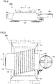
- Fig. 1 is a perspective view illustrating the outer appearance of a vehicular transformer according to a first embodiment of the present invention.
- Fig. 2 is a plan view of the vehicular transformer when viewed from the direction of an arrow II in Fig. 1 .
- Fig. 3 is a front view of the vehicular transformer when viewed from the direction of an arrow III in Fig. 1 .
- Fig. 4 is a left side view of the vehicular transformer when viewed from the direction of an arrow IV in Fig. 1 .
- Fig. 5 is a right side view of the vehicular transformer when viewed from the direction of an arrow V in Fig. 1 .
- a vehicular transformer 100 according to the first embodiment of the present invention is mounted on the roof of a vehicle. As illustrated in Figs. 1 to 5 , the vehicular transformer 100 according to the first embodiment of the present invention includes a tank 110, a plurality of cooling pipes 120, and a conservator 140.
- the tank 110 is configured to house a transformer body (not shown), and is filled with insulating oil which serves as refrigerant.
- the transformer body includes an iron core and a winding wound around the iron core.
- the iron core and the winding are housed in the tank 110 and immersed in the insulating oil.
- the tank 110 is connected to a pump (not shown) for circulating the insulating oil.
- the plurality of cooling pipes 120 are arranged above the tank 110.
- each of the plurality of cooling pipes 120 extends along a width direction 2 of the vehicle perpendicular to a travelling direction 1 of the vehicle.
- Each of the plurality of cooling pipes 120 is cylindrical in profile.
- Each of the plurality of cooling pipes 120 is made of a metal having high thermal conductivity such as stainless steel, copper or aluminum.
- the plurality of cooling pipes 120 are arranged side by side in the height direction and are arranged side by side in the horizontal direction at each height. In the present embodiment, the plurality of cooling pipes 120 are arranged side by side in the travelling direction 1 of the vehicle at each height.
- the number of the cooling pipes 120 arranged in the horizontal direction at each height is greater than the number of the cooling pipes 120 arranged in the height direction. For example, if the number of the cooling pipes 120 arranged in the horizontal direction at each height is 15 and the number of the cooling pipes 120 arranged in the height direction is 4, the total number of the plurality of cooling pipes 120 is 60.
- each of the plurality of cooling pipes 120 is connected to a first header 130, and the other end of each of the plurality of cooling pipes 120 is connected to a second header 131.
- Each of the plurality of cooling pipes 120 is in communication with the first header 130 and the second header 131.
- the first header 130 and the second header 131 are spaced apart from each other in the width direction 2 of the vehicle and extend along the travelling direction 1 of the vehicle.
- Each of the first header 130 and the second header 131 is connected to the upper surface of the tank 110 through a piping so as to be in communication with the tank 110.
- the insulating oil in the tank 110 is circulated so as to flow through the first header 130, the plurality of cooling pipes 120 and the second header 131, and back to the tank 110. As the insulating oil flows through the plurality of cooling pipes 120, it is cooled by exchanging heat with the outside air.
- the conservator 140 is arranged laterally to the tank 110 in alignment with the tank 110 along the travelling direction 1 of the vehicle. When viewed from the travelling direction 1 of the vehicle, the conservator 140 and the plurality of cooling pipes 120 do not overlap.
- the conservator 140 is in communication with the tank 110.
- the conservator 140 is provided to cope with the volume change of the insulating oil due to the temperature thereof. Specifically, when the temperature of the insulating oil in the tank 110 is raised, the insulating oil expands, and thereby, the insulating oil flows from the tank 110 into the conservator 140, and when the temperature of the insulating oil in the tank 110 is lowered, the insulating oil shrinks, and thereby, the insulating oil flows from the conservator 140 back into the tank 110.
- the vehicular transformer 100 further includes an inclination portion which is configured to ascend obliquely toward the transformer body and extend toward the plurality of cooling pipes 120.
- the vehicular transformer 100 includes a first inclination portion 150, a second inclination portion 151, a third inclination portion 152, and a fourth inclination portion 153.
- the first inclination portion 150 is provided on the left side of the tank 110.
- the second inclination portion 151 is provided on the right side of the tank 110.
- the third inclination portion 152 is provided on the front side of the tank 110.
- the fourth inclination portion 153 is provided on the rear side of the tank 110.
- Each of the first inclination portion 150, the second inclination portion 151, the third inclination portion 152 and the fourth inclination portion 153 may be formed as a part of the outer wall of the tank 110 or as a different member separate from the tank 110.
- Each of the first inclination portion 150, the second inclination portion 151, the third inclination portion 152, and the fourth inclination portion 153 is configured to guide the wind blowing against the vehicular transformer 100 to hit the plurality of cooling pipes 120.
- the first inclination portion 150 and the second inclination portion 151 guide the wind blowing in the travelling direction 1 of the vehicle to hit the plurality of cooling pipes 120.
- the third inclination portion 152 and the fourth inclination portion 153 guide the wind blowing in the width direction 2 of the vehicle to hit the plurality of cooling pipes 120.
- the plurality of cooling pipes 120 are arranged above the tank 110, it is easy for the travelling wind generated during the travelling of the vehicle to hit the plurality of cooling pipes 120, which makes it possible to efficiently cool the refrigerant flowing through the plurality of cooling pipes 120.
- the number of the cooling pipes 120 arranged in the horizontal direction at each height is greater than the number of the cooling pipes 120 arranged in the height direction, it is possible to increase the footprint of the plurality of cooling pipes 120 so as to provide the vehicular transformer 100 in a low profile.
- the vehicular transformer 100 is provided with an inclination portion configured to guide the wind blowing against the vehicular transformer 100 to hit the plurality of cooling pipes 120, it is possible to further efficiently cool the refrigerant flowing through the plurality of cooling pipes 120.
- the vehicular transformer according to the second embodiment of the present invention is different from the vehicular transformer 100 according to the first embodiment of the present invention mainly on the shape of each of the plurality of cooling pipes and the connection mode between the header and the tank, the description of the same components as those in the vehicular transformer 100 according to the first embodiment of the present invention will not be repeated.
- Fig. 6 is a perspective view illustrating the outer appearance of a vehicular transformer 200 according to the second embodiment of the present invention.
- the vehicular transformer 200 according to the second embodiment of the present invention includes a tank 110, a plurality of cooling pipes 220, and a conservator 140.
- each of the plurality of cooling pipes 220 includes a first leg portion 221 and a second leg portion 223, each of which extends in the height direction, and a horizontal portion 222 which extends in the width direction 2 of the vehicle.
- One end of the horizontal portion 222 is connected to the other end of the first leg portion 221, and the other end of the horizontal portion 222 is connected to the other end of the second leg portion 223.
- One end of the first leg portion 221 of each of the plurality of cooling pipes 220 is connected to the first header 230, and one end of the second leg portion 223 of each of the plurality of cooling pipes 220 is connected to the second header 231.
- Each of the plurality of cooling pipes 220 is in communication with each of the first header 230 and the second header 231.
- the first header 230 and the second header 231 are spaced apart from each other in the width direction 2 of the vehicle, and extend along the travelling direction 1 of the vehicle.
- Each of the first header 230 and the second header 231 is integrally formed on the upper portion of the tank 110.
- the plurality of cooling pipes 220, the first header 230 and the second header 231 also serve as reinforcing members of the tank 110, and thereby, the rigidity of the tank 110 itself can be reduced, which makes it possible to make the tank 110 thinner and smaller. Consequently, it is possible to make the vehicular transformer 200 smaller and lighter.
- Fig. 7 is a front view illustrating the outer appearance of a vehicular transformer 200a according to a first modification to the second embodiment of the present invention.
- the height of the first leg portion 221 and the height of the second leg portion 223 of the plurality of cooling pipes 220 are configured to increase gradually toward one side of the travelling direction 1 of the vehicle.
- Fig. 8 is a front view illustrating the outer appearance of a vehicular transformer 200b according to a second modification to the second embodiment of the present invention.
- the height of the first leg portion 221 and the height of the second leg portion 223 of the plurality of cooling pipes 220 are configured to decrease gradually to a certain height and then increase gradually to the original height toward one side of the travelling direction 1 of the vehicle.
- the wind blowing toward one side in the travelling direction 1 of the vehicle first hits the first cooling pipe arranged on the other side in the travelling direction 1 of the vehicle, and thereby, a vortex is formed around the first cooling pipe hit by the wind. Due to the vortex, the wind which hits the first cooling pipe arranged on the other side is guided toward one side in the travelling direction 1 of the vehicle while being subjected to a downward force so as to hit the second cooling pipe from the other side. A vortex is also formed around the second cooling pipe from the other side, and thereby, the wind which hits the second cooling pipe from the other side is guided toward one side in the travelling direction 1 of the vehicle while being subjected to a downward force so as to hit the third cooling pipe from the other side.
- the wind blowing toward one side in the travelling direction 1 of the vehicle forms a vortex around each cooling pipe so as to pass through the plurality of cooling pipes 220 descending sequentially as illustrated by the dotted line in Fig. 8 .
- the wind blowing toward one side in the travelling direction 1 of the vehicle smoothly passes through the plurality of cooling pipes 220, which makes it possible to improve the cooling efficiency.
- the wind blowing toward the other side in the travelling direction 1 of the vehicle first hits the first cooling pipe arranged at one side in the travelling direction 1 of the vehicle, and thereby, a vortex is formed around the first cooling pipe hit by the wind. Due to the vortex, the wind which hits the first cooling pipe arranged on one side is guided toward the other side in the travelling direction 1 of the vehicle while being subjected to a downward force so as to hit the second cooling pipe from one side. A vortex is also formed around the second cooling pipe from one side and the wind which hits the second cooling pipe from one side is subjected to a downward force and the wind on the other side in the travelling direction 1 of the vehicle and hits the third cooling pipe from one side.
- the wind blowing toward the other side in the travelling direction 1 of the vehicle forms a vortex around each cooling pipe so as to pass through the plurality of cooling pipes 220 descending sequentially as illustrated by the dotted line in Fig. 8 .
- the wind blowing toward the other side in the travelling direction 1 of the vehicle smoothly passes through the plurality of cooling pipes 220, which makes it possible to improve the cooling efficiency.
- the vehicular transformer 200b since the wind blowing toward either side of the travelling direction 1 of the vehicle efficiently hits the plurality of cooling pipes 220, it is possible to improve the cooling efficiency of the refrigerant.
- Fig. 9 is a plan view illustrating the outer appearance of a vehicular transformer 200c according to a third modification to the second embodiment of the present invention.
- the positions of the plurality of cooling pipes 220 in the width direction 2 of the vehicle are shifted to one side of the width direction 2 of the vehicle as the plurality of cooling pipes approach to one side of the travelling direction 1 of the vehicle.
- Fig. 10 is a plan view illustrating a tank and a plurality of cooling pipes of a vehicular transformer 200d according to a fourth modification to the second embodiment of the present invention when viewed from the top.
- Fig. 11 is a cross-sectional view illustrating a part of the plurality of cooling pipes illustrated in Fig. 10 when viewed from the direction of an arrow line XI-XI.
- each of the plurality of cooling pipes 220 is a flat pipe, and the plurality of cooling pipes 220 cover the tank 110 when viewed from above the tank 110.
- each of the horizontal portions 222 of the plurality of cooling pipes 220 the flat pipes are arranged such that the flat surfaces are orthogonal to the height direction.
- the plurality of cooling pipes 220 are arranged in a staggered manner when viewed from the extending direction of the horizontal portion 222.
- the plurality of cooling pipes 220 are arranged with no gap in the travelling direction 1 of the vehicle.
- the plurality of cooling pipes 220 cover the entire surface of the tank 110 when viewed from above the tank 110.
- the magnetic flux leaked from the transformer body may be shielded by the plurality of cooling pipes 220.
- the vehicular transformer according to the third embodiment of the present invention is different from the vehicular transformer 200 according to the second embodiment of the present invention mainly on the extending direction of the plurality of cooling pipes and the arrangement of the headers, the description of the same components as those in the vehicular transformer 200 according to the second embodiment of the present invention will not be repeated.
- Fig. 12 is a perspective view illustrating the outer appearance of a vehicular transformer 300 according to the third embodiment of the present invention.
- the vehicular transformer 300 according to the third embodiment of the present invention includes a tank 110, a plurality of cooling pipes 320, and a conservator 140.
- each of the plurality of cooling pipes 320 includes a first leg portion 321 and a second leg portion 323, each of which extends in the height direction, and a horizontal portion 322 which extends in the travelling direction 1 of the vehicle.
- One end of the horizontal portion 322 is connected to the other end of the first leg portion 321, and the other end of the horizontal portion 322 is connected to the other end of the second leg portion 323.
- One end of the first leg portion 321 of each of the plurality of cooling pipes 320 is connected to the first header 330, and one end of the second leg portion 323 of each of the plurality of cooling pipes 320 is connected to the second header 331.
- Each of the plurality of cooling pipes 320 is in communication with each of the first header 330 and the second header 331.
- the first header 330 and the second header 331 are spaced apart from each other in the travelling direction 1 of the vehicle, and extend along the width direction 2 of the vehicle.
- Each of the first header 330 and the second header 331 is integrally formed on the upper portion of the tank 110.
- the plurality of cooling pipes 320, the first header 330 and the second header 331 also serve as reinforcing members of the tank 110, and thereby, the rigidity of the tank 110 itself can be reduced, which makes it possible to make the tank 110 thinner and smaller. Consequently, it is possible to make the vehicular transformer 300 smaller and lighter.
- each of the plurality of cooling pipes 320 extends along the travelling direction 1 of the vehicle, the travelling wind generated during the travelling of the vehicle equivalently hits each of the plurality of cooling pipes 320, it is possible to efficiently cool the refrigerant flowing through the cooling pipe 320.
- 1 traveling direction of vehicle; 2: width direction of vehicle; 100, 200, 200a, 200b, 200c, 200d, 300: vehicular transformer; 110: tank; 120, 220, 320: cooling pipe; 130, 230, 330: first header; 131, 231, 331: second header; 140: conservator; 150: first inclination portion; 151: second inclination portion; 152: third inclination portion; 153: fourth inclination portion; 221, 321: first leg portion; 222, 322: horizontal portion; 223, 323: second leg portion
Landscapes
- Engineering & Computer Science (AREA)
- Power Engineering (AREA)
- Transformer Cooling (AREA)
Abstract
Description
- The present invention relates to a vehicular transformer.
- Japanese Patent No.
5805354 Patent Literature 1, the transformer body and the cooler are arranged side by side on the roof of a vehicle along the travelling direction of the vehicle. - Japanese Patent Laying-open No.
2006-269694 Patent Literature 2, the radiator is arranged above the main container. -
- PTL 1: Japanese Patent No.
5805354 - PTL 2: Japanese Patent Laying-open No.
2006-269694 - In a transformer in which insulating oil is circulated as refrigerant, a conservator is usually arranged above the transformer body. Thus, the transformer body and the cooler are arranged side by side along the travelling direction of the vehicle. The power device described in
Patent Literature 2 is configured to condense the refrigerant evaporated from the evaporator by using the radiator, and thereby is not provided with a conservator. - As described in
Patent Literature 1, in the case where the transformer body and the cooler are arranged in the vehicular transformer side by side along the travelling direction of the vehicle, there is still a room left for improving the cooling efficiency of the refrigerant by using travelling wind generated during the travelling of the vehicle. - The present invention has been made in view of the above problems, and an object thereof is to provide a vehicular transformer configured to improve the cooling efficiency of refrigerant by using the travelling wind generated during the travelling of a vehicle.
- A vehicular transformer according to the present invention is mounted on the roof of a vehicle. The vehicular transformer includes a tank, a plurality of cooling pipes and a conservator. The tank is configured to house a transformer body and is filled with refrigerant. The plurality of cooling pipes are arranged above the tank and configured to cool the refrigerant by heat exchange between the refrigerant and the outside air. The conservator is arranged laterally to the tank in alignment with the tank along a travelling direction of the vehicle and configured to be in communication with the tank.
- According to the present invention, it is possible to improve the cooling efficiency of refrigerant by using the travelling wind generated during the travelling of the vehicle.
-
-
Fig. 1 is a perspective view illustrating the outer appearance of a vehicular transformer according to a first embodiment of the present invention; -
Fig. 2 is a plan view of the vehicular transformer when viewed from the direction of an arrow II inFig. 1 ; -
Fig. 3 is a front view of the vehicular transformer when viewed from the direction of an arrow III inFig. 1 ; -
Fig. 4 is a left side view of the vehicular transformer when viewed from the direction of an arrow IV inFig. 1 ; -
Fig. 5 is a right side view of the vehicular transformer when viewed from the direction of an arrow V inFig. 1 ; -
Fig. 6 is a perspective view illustrating the outer appearance of a vehicular transformer according to a second embodiment of the present invention; -
Fig. 7 is a front view illustrating the outer appearance of a vehicular transformer according to a first modification to the second embodiment of the present invention; -
Fig. 8 is a front view illustrating the outer appearance of a vehicular transformer according to a second modification to the second embodiment of the present invention; -
Fig. 9 is a plan view illustrating the outer appearance of a vehicular transformer according to a third modification to the second embodiment of the present invention; -
Fig. 10 is a plan view illustrating a tank and a plurality of cooling pipes of a vehicular transformer when viewed from the above according to a fourth modification to the second embodiment of the present invention; -
Fig. 11 is a cross-sectional view illustrating a part of the plurality of cooling pipes illustrated inFig. 10 when viewed from the direction of an arrow line XI-XI; and -
Fig. 12 is a perspective view illustrating the outer appearance of a vehicular transformer according to a third embodiment of the present invention. - Hereinafter, a vehicular transformer according to each embodiment of the present invention will be described with reference to the drawings. In the following description of each embodiment, the same or corresponding parts in the drawings are denoted by the same reference numerals, and the description thereof will not be repeated.
-
Fig. 1 is a perspective view illustrating the outer appearance of a vehicular transformer according to a first embodiment of the present invention.Fig. 2 is a plan view of the vehicular transformer when viewed from the direction of an arrow II inFig. 1 .Fig. 3 is a front view of the vehicular transformer when viewed from the direction of an arrow III inFig. 1 .Fig. 4 is a left side view of the vehicular transformer when viewed from the direction of an arrow IV inFig. 1 .Fig. 5 is a right side view of the vehicular transformer when viewed from the direction of an arrow V inFig. 1 . - A
vehicular transformer 100 according to the first embodiment of the present invention is mounted on the roof of a vehicle. As illustrated inFigs. 1 to 5 , thevehicular transformer 100 according to the first embodiment of the present invention includes atank 110, a plurality ofcooling pipes 120, and aconservator 140. - The
tank 110 is configured to house a transformer body (not shown), and is filled with insulating oil which serves as refrigerant. The transformer body includes an iron core and a winding wound around the iron core. The iron core and the winding are housed in thetank 110 and immersed in the insulating oil. Thetank 110 is connected to a pump (not shown) for circulating the insulating oil. - The plurality of
cooling pipes 120 are arranged above thetank 110. In the present embodiment, each of the plurality ofcooling pipes 120 extends along awidth direction 2 of the vehicle perpendicular to atravelling direction 1 of the vehicle. Each of the plurality ofcooling pipes 120 is cylindrical in profile. Each of the plurality ofcooling pipes 120 is made of a metal having high thermal conductivity such as stainless steel, copper or aluminum. - The plurality of
cooling pipes 120 are arranged side by side in the height direction and are arranged side by side in the horizontal direction at each height. In the present embodiment, the plurality ofcooling pipes 120 are arranged side by side in thetravelling direction 1 of the vehicle at each height. The number of thecooling pipes 120 arranged in the horizontal direction at each height is greater than the number of thecooling pipes 120 arranged in the height direction. For example, if the number of thecooling pipes 120 arranged in the horizontal direction at each height is 15 and the number of thecooling pipes 120 arranged in the height direction is 4, the total number of the plurality ofcooling pipes 120 is 60. - One end of each of the plurality of
cooling pipes 120 is connected to afirst header 130, and the other end of each of the plurality ofcooling pipes 120 is connected to asecond header 131. Each of the plurality ofcooling pipes 120 is in communication with thefirst header 130 and thesecond header 131. - The
first header 130 and thesecond header 131 are spaced apart from each other in thewidth direction 2 of the vehicle and extend along thetravelling direction 1 of the vehicle. Each of thefirst header 130 and thesecond header 131 is connected to the upper surface of thetank 110 through a piping so as to be in communication with thetank 110. - As the pump is actuated, the insulating oil in the
tank 110 is circulated so as to flow through thefirst header 130, the plurality ofcooling pipes 120 and thesecond header 131, and back to thetank 110. As the insulating oil flows through the plurality of coolingpipes 120, it is cooled by exchanging heat with the outside air. - The
conservator 140 is arranged laterally to thetank 110 in alignment with thetank 110 along the travellingdirection 1 of the vehicle. When viewed from the travellingdirection 1 of the vehicle, theconservator 140 and the plurality of coolingpipes 120 do not overlap. - The
conservator 140 is in communication with thetank 110. Theconservator 140 is provided to cope with the volume change of the insulating oil due to the temperature thereof. Specifically, when the temperature of the insulating oil in thetank 110 is raised, the insulating oil expands, and thereby, the insulating oil flows from thetank 110 into theconservator 140, and when the temperature of the insulating oil in thetank 110 is lowered, the insulating oil shrinks, and thereby, the insulating oil flows from theconservator 140 back into thetank 110. - The
vehicular transformer 100 further includes an inclination portion which is configured to ascend obliquely toward the transformer body and extend toward the plurality of coolingpipes 120. Specifically, thevehicular transformer 100 includes afirst inclination portion 150, asecond inclination portion 151, athird inclination portion 152, and afourth inclination portion 153. - The
first inclination portion 150 is provided on the left side of thetank 110. Thesecond inclination portion 151 is provided on the right side of thetank 110. Thethird inclination portion 152 is provided on the front side of thetank 110. Thefourth inclination portion 153 is provided on the rear side of thetank 110. - Each of the
first inclination portion 150, thesecond inclination portion 151, thethird inclination portion 152 and thefourth inclination portion 153 may be formed as a part of the outer wall of thetank 110 or as a different member separate from thetank 110. - Each of the
first inclination portion 150, thesecond inclination portion 151, thethird inclination portion 152, and thefourth inclination portion 153 is configured to guide the wind blowing against thevehicular transformer 100 to hit the plurality of coolingpipes 120. Specifically, thefirst inclination portion 150 and thesecond inclination portion 151 guide the wind blowing in the travellingdirection 1 of the vehicle to hit the plurality of coolingpipes 120. Thethird inclination portion 152 and thefourth inclination portion 153 guide the wind blowing in thewidth direction 2 of the vehicle to hit the plurality of coolingpipes 120. - In the
vehicular transformer 100 according to the first embodiment of the present invention, since the plurality of coolingpipes 120 are arranged above thetank 110, it is easy for the travelling wind generated during the travelling of the vehicle to hit the plurality of coolingpipes 120, which makes it possible to efficiently cool the refrigerant flowing through the plurality of coolingpipes 120. - Since the number of the cooling
pipes 120 arranged in the horizontal direction at each height is greater than the number of the coolingpipes 120 arranged in the height direction, it is possible to increase the footprint of the plurality of coolingpipes 120 so as to provide thevehicular transformer 100 in a low profile. - Since the
vehicular transformer 100 is provided with an inclination portion configured to guide the wind blowing against thevehicular transformer 100 to hit the plurality of coolingpipes 120, it is possible to further efficiently cool the refrigerant flowing through the plurality of coolingpipes 120. - Hereinafter, a vehicular transformer according to a second embodiment of the present invention will be described with reference to the drawings. The vehicular transformer according to the second embodiment of the present invention is different from the
vehicular transformer 100 according to the first embodiment of the present invention mainly on the shape of each of the plurality of cooling pipes and the connection mode between the header and the tank, the description of the same components as those in thevehicular transformer 100 according to the first embodiment of the present invention will not be repeated. -
Fig. 6 is a perspective view illustrating the outer appearance of avehicular transformer 200 according to the second embodiment of the present invention. As illustrated inFig. 6 , thevehicular transformer 200 according to the second embodiment of the present invention includes atank 110, a plurality of coolingpipes 220, and aconservator 140. - The plurality of cooling
pipes 220 are arranged above thetank 110. In the present embodiment, each of the plurality of coolingpipes 220 includes afirst leg portion 221 and asecond leg portion 223, each of which extends in the height direction, and ahorizontal portion 222 which extends in thewidth direction 2 of the vehicle. One end of thehorizontal portion 222 is connected to the other end of thefirst leg portion 221, and the other end of thehorizontal portion 222 is connected to the other end of thesecond leg portion 223. - One end of the
first leg portion 221 of each of the plurality of coolingpipes 220 is connected to the first header 230, and one end of thesecond leg portion 223 of each of the plurality of coolingpipes 220 is connected to thesecond header 231. Each of the plurality of coolingpipes 220 is in communication with each of the first header 230 and thesecond header 231. - The first header 230 and the
second header 231 are spaced apart from each other in thewidth direction 2 of the vehicle, and extend along the travellingdirection 1 of the vehicle. Each of the first header 230 and thesecond header 231 is integrally formed on the upper portion of thetank 110. - In the
vehicular transformer 200 according to the second embodiment of the present invention, the plurality of coolingpipes 220, the first header 230 and thesecond header 231 also serve as reinforcing members of thetank 110, and thereby, the rigidity of thetank 110 itself can be reduced, which makes it possible to make thetank 110 thinner and smaller. Consequently, it is possible to make thevehicular transformer 200 smaller and lighter. - Hereinafter, modifications of the vehicular transformer according to the second embodiment of the present invention will be described with reference to the drawings.
-
Fig. 7 is a front view illustrating the outer appearance of avehicular transformer 200a according to a first modification to the second embodiment of the present invention. As illustrated inFig. 7 , in thevehicular transformer 200a according to the first modification to the second embodiment of the present invention, the height of thefirst leg portion 221 and the height of thesecond leg portion 223 of the plurality of coolingpipes 220 are configured to increase gradually toward one side of the travellingdirection 1 of the vehicle. - As a result, as the wind blowing toward one side of the travelling
direction 1 of the vehicle passes through the plurality of coolingpipes 220, it sequentially hits the coolingpipes 220 with increasing heights. As a result, in thevehicular transformer 200a, since the wind blowing toward one side of the travellingdirection 1 of the vehicle efficiently hits the plurality of coolingpipes 220, it is possible to improve the cooling efficiency of the refrigerant. -
Fig. 8 is a front view illustrating the outer appearance of avehicular transformer 200b according to a second modification to the second embodiment of the present invention. As illustrated inFig. 8 , in thevehicular transformer 200b according to the second modification to the second embodiment of the present invention, the height of thefirst leg portion 221 and the height of thesecond leg portion 223 of the plurality of coolingpipes 220 are configured to decrease gradually to a certain height and then increase gradually to the original height toward one side of the travellingdirection 1 of the vehicle. - As a result, the wind blowing toward one side in the travelling
direction 1 of the vehicle first hits the first cooling pipe arranged on the other side in the travellingdirection 1 of the vehicle, and thereby, a vortex is formed around the first cooling pipe hit by the wind. Due to the vortex, the wind which hits the first cooling pipe arranged on the other side is guided toward one side in the travellingdirection 1 of the vehicle while being subjected to a downward force so as to hit the second cooling pipe from the other side. A vortex is also formed around the second cooling pipe from the other side, and thereby, the wind which hits the second cooling pipe from the other side is guided toward one side in the travellingdirection 1 of the vehicle while being subjected to a downward force so as to hit the third cooling pipe from the other side. - As described above, in the present modification, the wind blowing toward one side in the travelling
direction 1 of the vehicle forms a vortex around each cooling pipe so as to pass through the plurality of coolingpipes 220 descending sequentially as illustrated by the dotted line inFig. 8 . Thus, in the present modification, compared to the first embodiment, the wind blowing toward one side in the travellingdirection 1 of the vehicle smoothly passes through the plurality of coolingpipes 220, which makes it possible to improve the cooling efficiency. - On the other hand, the wind blowing toward the other side in the travelling
direction 1 of the vehicle first hits the first cooling pipe arranged at one side in the travellingdirection 1 of the vehicle, and thereby, a vortex is formed around the first cooling pipe hit by the wind. Due to the vortex, the wind which hits the first cooling pipe arranged on one side is guided toward the other side in the travellingdirection 1 of the vehicle while being subjected to a downward force so as to hit the second cooling pipe from one side. A vortex is also formed around the second cooling pipe from one side and the wind which hits the second cooling pipe from one side is subjected to a downward force and the wind on the other side in the travellingdirection 1 of the vehicle and hits the third cooling pipe from one side. - As described above, in the present modification, the wind blowing toward the other side in the travelling
direction 1 of the vehicle forms a vortex around each cooling pipe so as to pass through the plurality of coolingpipes 220 descending sequentially as illustrated by the dotted line inFig. 8 . Thus, in the present modification, compared to the first embodiment, the wind blowing toward the other side in the travellingdirection 1 of the vehicle smoothly passes through the plurality of coolingpipes 220, which makes it possible to improve the cooling efficiency. - As described above, in the
vehicular transformer 200b, since the wind blowing toward either side of the travellingdirection 1 of the vehicle efficiently hits the plurality of coolingpipes 220, it is possible to improve the cooling efficiency of the refrigerant. -
Fig. 9 is a plan view illustrating the outer appearance of avehicular transformer 200c according to a third modification to the second embodiment of the present invention. As illustrated inFig. 9 , in thevehicular transformer 200c according to the third modification to the second embodiment of the present invention, the positions of the plurality of coolingpipes 220 in thewidth direction 2 of the vehicle are shifted to one side of thewidth direction 2 of the vehicle as the plurality of cooling pipes approach to one side of the travellingdirection 1 of the vehicle. - As a result, as the wind blowing toward one side in the travelling
direction 1 of the vehicle passes through the plurality of coolingpipes 220, it sequentially hits the cooling pipe shifted to one side of thewidth direction 2 of the vehicle. On the other hand, as the wind blowing toward the other side in the travellingdirection 1 of the vehicle passes through the plurality of coolingpipes 220, it sequentially hits the cooling pipe shifted to the other side of thewidth direction 2 of the vehicle. As a result, in thevehicular transformer 200c, since the wind blowing toward either side of the travellingdirection 1 of the vehicle efficiently hits the plurality of coolingpipes 220, it is possible to improve the cooling efficiency of the refrigerant. -
Fig. 10 is a plan view illustrating a tank and a plurality of cooling pipes of avehicular transformer 200d according to a fourth modification to the second embodiment of the present invention when viewed from the top.Fig. 11 is a cross-sectional view illustrating a part of the plurality of cooling pipes illustrated inFig. 10 when viewed from the direction of an arrow line XI-XI. As illustrated inFigs. 10 and 11 , in thevehicular transformer 200d according to the fourth modification to the second embodiment of the present invention, each of the plurality of coolingpipes 220 is a flat pipe, and the plurality of coolingpipes 220 cover thetank 110 when viewed from above thetank 110. - Specifically, in each of the
horizontal portions 222 of the plurality of coolingpipes 220, the flat pipes are arranged such that the flat surfaces are orthogonal to the height direction. The plurality of coolingpipes 220 are arranged in a staggered manner when viewed from the extending direction of thehorizontal portion 222. When viewed from above thetank 110, the plurality of coolingpipes 220 are arranged with no gap in the travellingdirection 1 of the vehicle. The plurality of coolingpipes 220 cover the entire surface of thetank 110 when viewed from above thetank 110. - Thereby, the magnetic flux leaked from the transformer body may be shielded by the plurality of cooling
pipes 220. As a result, it is possible to reduce the magnetic flux leaked to the outside of thetank 110, which makes it possible to dispose electronic components which are susceptible to magnetic flux around thevehicular transformer 200d. - Hereinafter, a vehicular transformer according to a third embodiment of the present invention will be described with reference to the drawings. The vehicular transformer according to the third embodiment of the present invention is different from the
vehicular transformer 200 according to the second embodiment of the present invention mainly on the extending direction of the plurality of cooling pipes and the arrangement of the headers, the description of the same components as those in thevehicular transformer 200 according to the second embodiment of the present invention will not be repeated. -
Fig. 12 is a perspective view illustrating the outer appearance of avehicular transformer 300 according to the third embodiment of the present invention. As illustrated inFig. 12 , thevehicular transformer 300 according to the third embodiment of the present invention includes atank 110, a plurality of coolingpipes 320, and aconservator 140. - The plurality of cooling
pipes 320 are arranged above thetank 110. In the present embodiment, each of the plurality of coolingpipes 320 includes afirst leg portion 321 and asecond leg portion 323, each of which extends in the height direction, and ahorizontal portion 322 which extends in the travellingdirection 1 of the vehicle. One end of thehorizontal portion 322 is connected to the other end of thefirst leg portion 321, and the other end of thehorizontal portion 322 is connected to the other end of thesecond leg portion 323. - One end of the
first leg portion 321 of each of the plurality of coolingpipes 320 is connected to thefirst header 330, and one end of thesecond leg portion 323 of each of the plurality of coolingpipes 320 is connected to thesecond header 331. Each of the plurality of coolingpipes 320 is in communication with each of thefirst header 330 and thesecond header 331. - The
first header 330 and thesecond header 331 are spaced apart from each other in the travellingdirection 1 of the vehicle, and extend along thewidth direction 2 of the vehicle. Each of thefirst header 330 and thesecond header 331 is integrally formed on the upper portion of thetank 110. - In the
vehicular transformer 300 according to the third embodiment of the present invention, the plurality of coolingpipes 320, thefirst header 330 and thesecond header 331 also serve as reinforcing members of thetank 110, and thereby, the rigidity of thetank 110 itself can be reduced, which makes it possible to make thetank 110 thinner and smaller. Consequently, it is possible to make thevehicular transformer 300 smaller and lighter. - Furthermore, since each of the plurality of cooling
pipes 320 extends along the travellingdirection 1 of the vehicle, the travelling wind generated during the travelling of the vehicle equivalently hits each of the plurality of coolingpipes 320, it is possible to efficiently cool the refrigerant flowing through thecooling pipe 320. - It should be understood that the embodiments disclosed herein have been presented for the purpose of illustration and description but not limited in all aspects. It is intended that the scope of the present invention is not limited to the description above but defined by the scope of the claims and encompasses all modifications equivalent in meaning and scope to the claims.
- 1: traveling direction of vehicle; 2: width direction of vehicle; 100, 200, 200a, 200b, 200c, 200d, 300: vehicular transformer; 110: tank; 120, 220, 320: cooling pipe; 130, 230, 330: first header; 131, 231, 331: second header; 140: conservator; 150: first inclination portion; 151: second inclination portion; 152: third inclination portion; 153: fourth inclination portion; 221, 321: first leg portion; 222, 322: horizontal portion; 223, 323: second leg portion
Claims (6)
- A vehicular transformer mounted on the roof of a vehicle, comprising:a tank configured to house a transformer body and filled with refrigerant;a plurality of cooling pipes arranged above the tank and configured to cool the refrigerant by heat exchange between the refrigerant and the outside air; anda conservator arranged laterally to the tank in alignment with the tank along a travelling direction of the vehicle and configured to be in communication with the tank.
- The vehicular transformer according to claim 1, further comprising an inclination portion which is configured to ascend obliquely toward the transformer body and extend toward the plurality of cooling pipes.
- The vehicular transformer according to claim 1 or 2, wherein
the plurality of cooling pipes are arranged side by side in the height direction and arranged side by side in the horizontal direction at each height, and
the number of the cooling pipes arranged in the horizontal direction at each height is greater than the number of the cooling pipes arranged in the height direction. - The vehicular transformer according to any one of claims 1 to 3, wherein each of the plurality of cooling pipes is a flat pipe.
- The vehicular transformer according to any one of claims 1 to 4, wherein the plurality of cooling pipes cover the tank when viewed from above the tank.
- The vehicular transformer according to any one of claims 1 to 5, wherein each of the plurality of cooling pipes is configured to extend along the travelling direction of the vehicle.
Applications Claiming Priority (1)
| Application Number | Priority Date | Filing Date | Title |
|---|---|---|---|
| PCT/JP2016/076776 WO2018047327A1 (en) | 2016-09-12 | 2016-09-12 | Transformer for vehicles |
Publications (3)
| Publication Number | Publication Date |
|---|---|
| EP3511961A1 true EP3511961A1 (en) | 2019-07-17 |
| EP3511961A4 EP3511961A4 (en) | 2019-09-04 |
| EP3511961B1 EP3511961B1 (en) | 2021-11-03 |
Family
ID=59012066
Family Applications (1)
| Application Number | Title | Priority Date | Filing Date |
|---|---|---|---|
| EP16915745.0A Active EP3511961B1 (en) | 2016-09-12 | 2016-09-12 | Transformer for vehicles |
Country Status (4)
| Country | Link |
|---|---|
| EP (1) | EP3511961B1 (en) |
| JP (1) | JP6143983B1 (en) |
| CN (2) | CN115424825A (en) |
| WO (1) | WO2018047327A1 (en) |
Families Citing this family (2)
| Publication number | Priority date | Publication date | Assignee | Title |
|---|---|---|---|---|
| JP6548859B1 (en) * | 2018-11-15 | 2019-07-24 | 三菱電機株式会社 | Vehicle transformer |
| CN110517856A (en) * | 2019-09-12 | 2019-11-29 | 中车株洲电机有限公司 | A kind of transformer and the rolling stock with the transformer |
Family Cites Families (19)
| Publication number | Priority date | Publication date | Assignee | Title |
|---|---|---|---|---|
| JPS585354B2 (en) | 1974-11-06 | 1983-01-31 | ベイカ−ドリル.Inc | Impact type drilling device |
| JPS5818275Y2 (en) * | 1978-03-20 | 1983-04-13 | 株式会社東芝 | vehicle transformer |
| JPS5660765A (en) * | 1979-10-24 | 1981-05-25 | Mitsubishi Electric Corp | Cooler for electrical machinery and apparatus for car |
| JPS56162815A (en) * | 1980-05-20 | 1981-12-15 | Tamura Seisakusho Co Ltd | Bellows device |
| JPS57159220U (en) * | 1981-03-31 | 1982-10-06 | ||
| JP2619707B2 (en) * | 1988-11-26 | 1997-06-11 | 三菱電機株式会社 | Heat dissipation device |
| JP2003234443A (en) * | 2002-02-07 | 2003-08-22 | Furukawa Electric Co Ltd:The | Finned heat sink |
| JP2006269694A (en) | 2005-03-23 | 2006-10-05 | Nissin Electric Co Ltd | Power apparatus |
| JP4012230B2 (en) * | 2006-03-22 | 2007-11-21 | 三菱電機株式会社 | Automotive cooler |
| JP2007273777A (en) * | 2006-03-31 | 2007-10-18 | Toshiba Corp | Cooling device for vehicle transformer |
| US7760060B2 (en) * | 2006-07-10 | 2010-07-20 | Mitsubishi Electric Corporation | Vehicle transformer |
| CN201538317U (en) * | 2009-10-31 | 2010-08-04 | 中国北车集团大连机车研究所有限公司 | overhead cooling unit |
| CN201773670U (en) * | 2010-08-28 | 2011-03-23 | 中国北车集团大连机车车辆有限公司 | Full-sealed oil immersion traction transformer |
| TWM403013U (en) * | 2010-11-03 | 2011-05-01 | Enermax Tech Corporation | Heat dissipating device having swirl generator |
| CN202267039U (en) * | 2011-09-06 | 2012-06-06 | 幸雄科技股份有限公司 | Heat sink structure |
| JP5946651B2 (en) * | 2012-02-28 | 2016-07-06 | 住友精密工業株式会社 | Heat exchanger |
| CN204229989U (en) * | 2014-12-09 | 2015-03-25 | 张玮琦 | The insulating oil cooling back installation of locomotive transformer |
| WO2016103439A1 (en) * | 2014-12-26 | 2016-06-30 | 三菱電機株式会社 | Transformer for vehicle |
| JP6494384B2 (en) * | 2015-04-09 | 2019-04-03 | 三菱電機株式会社 | Transformer for vehicle |
-
2016
- 2016-09-12 JP JP2016574291A patent/JP6143983B1/en active Active
- 2016-09-12 CN CN202211197475.5A patent/CN115424825A/en active Pending
- 2016-09-12 EP EP16915745.0A patent/EP3511961B1/en active Active
- 2016-09-12 CN CN201680088882.9A patent/CN109643601A/en active Pending
- 2016-09-12 WO PCT/JP2016/076776 patent/WO2018047327A1/en not_active Ceased
Also Published As
| Publication number | Publication date |
|---|---|
| EP3511961B1 (en) | 2021-11-03 |
| JPWO2018047327A1 (en) | 2018-09-06 |
| WO2018047327A1 (en) | 2018-03-15 |
| EP3511961A4 (en) | 2019-09-04 |
| CN115424825A (en) | 2022-12-02 |
| CN109643601A (en) | 2019-04-16 |
| JP6143983B1 (en) | 2017-06-07 |
Similar Documents
| Publication | Publication Date | Title |
|---|---|---|
| KR102190366B1 (en) | Cooling module | |
| US8614613B2 (en) | Transformer | |
| CN201615547U (en) | Electric heater and radiating fin structure thereof | |
| JP6180684B1 (en) | Transformer for vehicle | |
| EP3511961A1 (en) | Transformer for vehicles | |
| JP4357571B2 (en) | Heat exchanger | |
| JP6494384B2 (en) | Transformer for vehicle | |
| JP6758522B2 (en) | Transformers and power converters | |
| JP4012230B2 (en) | Automotive cooler | |
| CN120413236A (en) | Oil-immersed high-voltage transformer | |
| CN205487648U (en) | Heat dissipation cooling device of transformer | |
| CN104654825B (en) | The guiding device of the air cooling unit with △ shape channel spaces | |
| JP6051641B2 (en) | Intercooler for vehicle | |
| EP3367398A1 (en) | Vehicle-use transformer | |
| JP2013185992A (en) | Cooling system for spent fuel storage pool | |
| CN202614072U (en) | Plate radiator for natural cycle oil-immersed transformer | |
| CN215868916U (en) | Transformer soft magnetic iron core with good heat dissipation effect | |
| CN208607992U (en) | A kind of high heat-flux mobile transformer radiating module and radiating module group | |
| CN216849568U (en) | Transformer oil tank with accelerated heat dissipation | |
| CN103335535B (en) | Air cooling unit deflector | |
| KR101167690B1 (en) | Cooling system for transformer | |
| CN219718903U (en) | Radiating pipe, electric control plate radiating structure and air conditioner | |
| CN221596125U (en) | Radiator and oil immersed transformer | |
| JP2009198172A (en) | Heat exchanger | |
| CN108847332A (en) | A kind of high heat-flux mobile transformer radiating module and radiating module group |
Legal Events
| Date | Code | Title | Description |
|---|---|---|---|
| STAA | Information on the status of an ep patent application or granted ep patent |
Free format text: STATUS: THE INTERNATIONAL PUBLICATION HAS BEEN MADE |
|
| PUAI | Public reference made under article 153(3) epc to a published international application that has entered the european phase |
Free format text: ORIGINAL CODE: 0009012 |
|
| STAA | Information on the status of an ep patent application or granted ep patent |
Free format text: STATUS: REQUEST FOR EXAMINATION WAS MADE |
|
| 17P | Request for examination filed |
Effective date: 20190118 |
|
| AK | Designated contracting states |
Kind code of ref document: A1 Designated state(s): AL AT BE BG CH CY CZ DE DK EE ES FI FR GB GR HR HU IE IS IT LI LT LU LV MC MK MT NL NO PL PT RO RS SE SI SK SM TR |
|
| AX | Request for extension of the european patent |
Extension state: BA ME |
|
| A4 | Supplementary search report drawn up and despatched |
Effective date: 20190802 |
|
| RIC1 | Information provided on ipc code assigned before grant |
Ipc: H01F 27/12 20060101ALI20190729BHEP Ipc: H01F 27/14 20060101AFI20190729BHEP Ipc: H01F 27/02 20060101ALI20190729BHEP Ipc: H01F 27/08 20060101ALI20190729BHEP |
|
| DAV | Request for validation of the european patent (deleted) | ||
| DAX | Request for extension of the european patent (deleted) | ||
| STAA | Information on the status of an ep patent application or granted ep patent |
Free format text: STATUS: EXAMINATION IS IN PROGRESS |
|
| 17Q | First examination report despatched |
Effective date: 20200312 |
|
| GRAJ | Information related to disapproval of communication of intention to grant by the applicant or resumption of examination proceedings by the epo deleted |
Free format text: ORIGINAL CODE: EPIDOSDIGR1 |
|
| STAA | Information on the status of an ep patent application or granted ep patent |
Free format text: STATUS: GRANT OF PATENT IS INTENDED |
|
| GRAP | Despatch of communication of intention to grant a patent |
Free format text: ORIGINAL CODE: EPIDOSNIGR1 |
|
| INTG | Intention to grant announced |
Effective date: 20210518 |
|
| GRAS | Grant fee paid |
Free format text: ORIGINAL CODE: EPIDOSNIGR3 |
|
| GRAA | (expected) grant |
Free format text: ORIGINAL CODE: 0009210 |
|
| STAA | Information on the status of an ep patent application or granted ep patent |
Free format text: STATUS: THE PATENT HAS BEEN GRANTED |
|
| AK | Designated contracting states |
Kind code of ref document: B1 Designated state(s): AL AT BE BG CH CY CZ DE DK EE ES FI FR GB GR HR HU IE IS IT LI LT LU LV MC MK MT NL NO PL PT RO RS SE SI SK SM TR |
|
| REG | Reference to a national code |
Ref country code: GB Ref legal event code: FG4D |
|
| REG | Reference to a national code |
Ref country code: AT Ref legal event code: REF Ref document number: 1444712 Country of ref document: AT Kind code of ref document: T Effective date: 20211115 Ref country code: CH Ref legal event code: EP |
|
| REG | Reference to a national code |
Ref country code: IE Ref legal event code: FG4D |
|
| REG | Reference to a national code |
Ref country code: DE Ref legal event code: R096 Ref document number: 602016065886 Country of ref document: DE |
|
| REG | Reference to a national code |
Ref country code: SE Ref legal event code: TRGR |
|
| REG | Reference to a national code |
Ref country code: LT Ref legal event code: MG9D |
|
| REG | Reference to a national code |
Ref country code: NL Ref legal event code: MP Effective date: 20211103 |
|
| REG | Reference to a national code |
Ref country code: AT Ref legal event code: MK05 Ref document number: 1444712 Country of ref document: AT Kind code of ref document: T Effective date: 20211103 |
|
| PG25 | Lapsed in a contracting state [announced via postgrant information from national office to epo] |
Ref country code: RS Free format text: LAPSE BECAUSE OF FAILURE TO SUBMIT A TRANSLATION OF THE DESCRIPTION OR TO PAY THE FEE WITHIN THE PRESCRIBED TIME-LIMIT Effective date: 20211103 Ref country code: LT Free format text: LAPSE BECAUSE OF FAILURE TO SUBMIT A TRANSLATION OF THE DESCRIPTION OR TO PAY THE FEE WITHIN THE PRESCRIBED TIME-LIMIT Effective date: 20211103 Ref country code: FI Free format text: LAPSE BECAUSE OF FAILURE TO SUBMIT A TRANSLATION OF THE DESCRIPTION OR TO PAY THE FEE WITHIN THE PRESCRIBED TIME-LIMIT Effective date: 20211103 Ref country code: BG Free format text: LAPSE BECAUSE OF FAILURE TO SUBMIT A TRANSLATION OF THE DESCRIPTION OR TO PAY THE FEE WITHIN THE PRESCRIBED TIME-LIMIT Effective date: 20220203 Ref country code: AT Free format text: LAPSE BECAUSE OF FAILURE TO SUBMIT A TRANSLATION OF THE DESCRIPTION OR TO PAY THE FEE WITHIN THE PRESCRIBED TIME-LIMIT Effective date: 20211103 |
|
| PG25 | Lapsed in a contracting state [announced via postgrant information from national office to epo] |
Ref country code: IS Free format text: LAPSE BECAUSE OF FAILURE TO SUBMIT A TRANSLATION OF THE DESCRIPTION OR TO PAY THE FEE WITHIN THE PRESCRIBED TIME-LIMIT Effective date: 20220303 Ref country code: PT Free format text: LAPSE BECAUSE OF FAILURE TO SUBMIT A TRANSLATION OF THE DESCRIPTION OR TO PAY THE FEE WITHIN THE PRESCRIBED TIME-LIMIT Effective date: 20220303 Ref country code: PL Free format text: LAPSE BECAUSE OF FAILURE TO SUBMIT A TRANSLATION OF THE DESCRIPTION OR TO PAY THE FEE WITHIN THE PRESCRIBED TIME-LIMIT Effective date: 20211103 Ref country code: NO Free format text: LAPSE BECAUSE OF FAILURE TO SUBMIT A TRANSLATION OF THE DESCRIPTION OR TO PAY THE FEE WITHIN THE PRESCRIBED TIME-LIMIT Effective date: 20220203 Ref country code: NL Free format text: LAPSE BECAUSE OF FAILURE TO SUBMIT A TRANSLATION OF THE DESCRIPTION OR TO PAY THE FEE WITHIN THE PRESCRIBED TIME-LIMIT Effective date: 20211103 Ref country code: LV Free format text: LAPSE BECAUSE OF FAILURE TO SUBMIT A TRANSLATION OF THE DESCRIPTION OR TO PAY THE FEE WITHIN THE PRESCRIBED TIME-LIMIT Effective date: 20211103 Ref country code: HR Free format text: LAPSE BECAUSE OF FAILURE TO SUBMIT A TRANSLATION OF THE DESCRIPTION OR TO PAY THE FEE WITHIN THE PRESCRIBED TIME-LIMIT Effective date: 20211103 Ref country code: GR Free format text: LAPSE BECAUSE OF FAILURE TO SUBMIT A TRANSLATION OF THE DESCRIPTION OR TO PAY THE FEE WITHIN THE PRESCRIBED TIME-LIMIT Effective date: 20220204 Ref country code: ES Free format text: LAPSE BECAUSE OF FAILURE TO SUBMIT A TRANSLATION OF THE DESCRIPTION OR TO PAY THE FEE WITHIN THE PRESCRIBED TIME-LIMIT Effective date: 20211103 |
|
| PG25 | Lapsed in a contracting state [announced via postgrant information from national office to epo] |
Ref country code: SM Free format text: LAPSE BECAUSE OF FAILURE TO SUBMIT A TRANSLATION OF THE DESCRIPTION OR TO PAY THE FEE WITHIN THE PRESCRIBED TIME-LIMIT Effective date: 20211103 Ref country code: SK Free format text: LAPSE BECAUSE OF FAILURE TO SUBMIT A TRANSLATION OF THE DESCRIPTION OR TO PAY THE FEE WITHIN THE PRESCRIBED TIME-LIMIT Effective date: 20211103 Ref country code: RO Free format text: LAPSE BECAUSE OF FAILURE TO SUBMIT A TRANSLATION OF THE DESCRIPTION OR TO PAY THE FEE WITHIN THE PRESCRIBED TIME-LIMIT Effective date: 20211103 Ref country code: EE Free format text: LAPSE BECAUSE OF FAILURE TO SUBMIT A TRANSLATION OF THE DESCRIPTION OR TO PAY THE FEE WITHIN THE PRESCRIBED TIME-LIMIT Effective date: 20211103 Ref country code: DK Free format text: LAPSE BECAUSE OF FAILURE TO SUBMIT A TRANSLATION OF THE DESCRIPTION OR TO PAY THE FEE WITHIN THE PRESCRIBED TIME-LIMIT Effective date: 20211103 Ref country code: CZ Free format text: LAPSE BECAUSE OF FAILURE TO SUBMIT A TRANSLATION OF THE DESCRIPTION OR TO PAY THE FEE WITHIN THE PRESCRIBED TIME-LIMIT Effective date: 20211103 |
|
| REG | Reference to a national code |
Ref country code: DE Ref legal event code: R097 Ref document number: 602016065886 Country of ref document: DE |
|
| PLBE | No opposition filed within time limit |
Free format text: ORIGINAL CODE: 0009261 |
|
| STAA | Information on the status of an ep patent application or granted ep patent |
Free format text: STATUS: NO OPPOSITION FILED WITHIN TIME LIMIT |
|
| 26N | No opposition filed |
Effective date: 20220804 |
|
| PG25 | Lapsed in a contracting state [announced via postgrant information from national office to epo] |
Ref country code: AL Free format text: LAPSE BECAUSE OF FAILURE TO SUBMIT A TRANSLATION OF THE DESCRIPTION OR TO PAY THE FEE WITHIN THE PRESCRIBED TIME-LIMIT Effective date: 20211103 |
|
| PG25 | Lapsed in a contracting state [announced via postgrant information from national office to epo] |
Ref country code: SI Free format text: LAPSE BECAUSE OF FAILURE TO SUBMIT A TRANSLATION OF THE DESCRIPTION OR TO PAY THE FEE WITHIN THE PRESCRIBED TIME-LIMIT Effective date: 20211103 |
|
| PG25 | Lapsed in a contracting state [announced via postgrant information from national office to epo] |
Ref country code: MC Free format text: LAPSE BECAUSE OF FAILURE TO SUBMIT A TRANSLATION OF THE DESCRIPTION OR TO PAY THE FEE WITHIN THE PRESCRIBED TIME-LIMIT Effective date: 20211103 |
|
| REG | Reference to a national code |
Ref country code: BE Ref legal event code: MM Effective date: 20220930 |
|
| PG25 | Lapsed in a contracting state [announced via postgrant information from national office to epo] |
Ref country code: IT Free format text: LAPSE BECAUSE OF FAILURE TO SUBMIT A TRANSLATION OF THE DESCRIPTION OR TO PAY THE FEE WITHIN THE PRESCRIBED TIME-LIMIT Effective date: 20211103 |
|
| P01 | Opt-out of the competence of the unified patent court (upc) registered |
Effective date: 20230512 |
|
| PG25 | Lapsed in a contracting state [announced via postgrant information from national office to epo] |
Ref country code: LU Free format text: LAPSE BECAUSE OF NON-PAYMENT OF DUE FEES Effective date: 20220912 |
|
| PG25 | Lapsed in a contracting state [announced via postgrant information from national office to epo] |
Ref country code: IE Free format text: LAPSE BECAUSE OF NON-PAYMENT OF DUE FEES Effective date: 20220912 |
|
| PG25 | Lapsed in a contracting state [announced via postgrant information from national office to epo] |
Ref country code: BE Free format text: LAPSE BECAUSE OF NON-PAYMENT OF DUE FEES Effective date: 20220930 |
|
| REG | Reference to a national code |
Ref country code: DE Ref legal event code: R084 Ref document number: 602016065886 Country of ref document: DE |
|
| PG25 | Lapsed in a contracting state [announced via postgrant information from national office to epo] |
Ref country code: HU Free format text: LAPSE BECAUSE OF FAILURE TO SUBMIT A TRANSLATION OF THE DESCRIPTION OR TO PAY THE FEE WITHIN THE PRESCRIBED TIME-LIMIT; INVALID AB INITIO Effective date: 20160912 |
|
| PG25 | Lapsed in a contracting state [announced via postgrant information from national office to epo] |
Ref country code: CY Free format text: LAPSE BECAUSE OF FAILURE TO SUBMIT A TRANSLATION OF THE DESCRIPTION OR TO PAY THE FEE WITHIN THE PRESCRIBED TIME-LIMIT Effective date: 20211103 |
|
| PG25 | Lapsed in a contracting state [announced via postgrant information from national office to epo] |
Ref country code: MK Free format text: LAPSE BECAUSE OF FAILURE TO SUBMIT A TRANSLATION OF THE DESCRIPTION OR TO PAY THE FEE WITHIN THE PRESCRIBED TIME-LIMIT Effective date: 20211103 |
|
| PG25 | Lapsed in a contracting state [announced via postgrant information from national office to epo] |
Ref country code: MT Free format text: LAPSE BECAUSE OF FAILURE TO SUBMIT A TRANSLATION OF THE DESCRIPTION OR TO PAY THE FEE WITHIN THE PRESCRIBED TIME-LIMIT Effective date: 20211103 |
|
| PGFP | Annual fee paid to national office [announced via postgrant information from national office to epo] |
Ref country code: GB Payment date: 20240801 Year of fee payment: 9 |
|
| PGFP | Annual fee paid to national office [announced via postgrant information from national office to epo] |
Ref country code: SE Payment date: 20240812 Year of fee payment: 9 |
|
| REG | Reference to a national code |
Ref country code: CH Ref legal event code: U11 Free format text: ST27 STATUS EVENT CODE: U-0-0-U10-U11 (AS PROVIDED BY THE NATIONAL OFFICE) Effective date: 20251001 |
|
| PGFP | Annual fee paid to national office [announced via postgrant information from national office to epo] |
Ref country code: DE Payment date: 20250730 Year of fee payment: 10 |
|
| PGFP | Annual fee paid to national office [announced via postgrant information from national office to epo] |
Ref country code: FR Payment date: 20250808 Year of fee payment: 10 |
|
| PG25 | Lapsed in a contracting state [announced via postgrant information from national office to epo] |
Ref country code: TR Free format text: LAPSE BECAUSE OF FAILURE TO SUBMIT A TRANSLATION OF THE DESCRIPTION OR TO PAY THE FEE WITHIN THE PRESCRIBED TIME-LIMIT Effective date: 20211103 |
|
| PGFP | Annual fee paid to national office [announced via postgrant information from national office to epo] |
Ref country code: CH Payment date: 20251001 Year of fee payment: 10 |