EP3511604B1 - Modulare geschlitzte hülse - Google Patents
Modulare geschlitzte hülse Download PDFInfo
- Publication number
- EP3511604B1 EP3511604B1 EP19151890.1A EP19151890A EP3511604B1 EP 3511604 B1 EP3511604 B1 EP 3511604B1 EP 19151890 A EP19151890 A EP 19151890A EP 3511604 B1 EP3511604 B1 EP 3511604B1
- Authority
- EP
- European Patent Office
- Prior art keywords
- segments
- fitting
- pipe
- mating
- adjacent
- Prior art date
- Legal status (The legal status is an assumption and is not a legal conclusion. Google has not performed a legal analysis and makes no representation as to the accuracy of the status listed.)
- Active
Links
- 230000013011 mating Effects 0.000 claims description 14
- 230000001010 compromised effect Effects 0.000 description 4
- 238000000926 separation method Methods 0.000 description 4
- 239000012530 fluid Substances 0.000 description 3
- 229910000831 Steel Inorganic materials 0.000 description 2
- 238000005299 abrasion Methods 0.000 description 2
- 238000005260 corrosion Methods 0.000 description 2
- 230000007797 corrosion Effects 0.000 description 2
- 238000004519 manufacturing process Methods 0.000 description 2
- 239000000463 material Substances 0.000 description 2
- 239000010959 steel Substances 0.000 description 2
- 230000003466 anti-cipated effect Effects 0.000 description 1
- 238000005266 casting Methods 0.000 description 1
- 238000004140 cleaning Methods 0.000 description 1
- 230000000694 effects Effects 0.000 description 1
- 239000013536 elastomeric material Substances 0.000 description 1
- 238000005242 forging Methods 0.000 description 1
- 238000009434 installation Methods 0.000 description 1
- 239000002184 metal Substances 0.000 description 1
- 238000000034 method Methods 0.000 description 1
- 238000012986 modification Methods 0.000 description 1
- 230000004048 modification Effects 0.000 description 1
Images


Classifications
-
- F—MECHANICAL ENGINEERING; LIGHTING; HEATING; WEAPONS; BLASTING
- F16—ENGINEERING ELEMENTS AND UNITS; GENERAL MEASURES FOR PRODUCING AND MAINTAINING EFFECTIVE FUNCTIONING OF MACHINES OR INSTALLATIONS; THERMAL INSULATION IN GENERAL
- F16L—PIPES; JOINTS OR FITTINGS FOR PIPES; SUPPORTS FOR PIPES, CABLES OR PROTECTIVE TUBING; MEANS FOR THERMAL INSULATION IN GENERAL
- F16L55/00—Devices or appurtenances for use in, or in connection with, pipes or pipe systems
- F16L55/16—Devices for covering leaks in pipes or hoses, e.g. hose-menders
- F16L55/168—Devices for covering leaks in pipes or hoses, e.g. hose-menders from outside the pipe
- F16L55/17—Devices for covering leaks in pipes or hoses, e.g. hose-menders from outside the pipe by means of rings, bands or sleeves pressed against the outside surface of the pipe or hose
- F16L55/172—Devices for covering leaks in pipes or hoses, e.g. hose-menders from outside the pipe by means of rings, bands or sleeves pressed against the outside surface of the pipe or hose the ring, band or sleeve being tightened by a tangentially arranged threaded pin and a nut
-
- F—MECHANICAL ENGINEERING; LIGHTING; HEATING; WEAPONS; BLASTING
- F16—ENGINEERING ELEMENTS AND UNITS; GENERAL MEASURES FOR PRODUCING AND MAINTAINING EFFECTIVE FUNCTIONING OF MACHINES OR INSTALLATIONS; THERMAL INSULATION IN GENERAL
- F16L—PIPES; JOINTS OR FITTINGS FOR PIPES; SUPPORTS FOR PIPES, CABLES OR PROTECTIVE TUBING; MEANS FOR THERMAL INSULATION IN GENERAL
- F16L21/00—Joints with sleeve or socket
- F16L21/06—Joints with sleeve or socket with a divided sleeve or ring clamping around the pipe-ends
- F16L21/065—Joints with sleeve or socket with a divided sleeve or ring clamping around the pipe-ends tightened by tangentially-arranged threaded pins
-
- F—MECHANICAL ENGINEERING; LIGHTING; HEATING; WEAPONS; BLASTING
- F16—ENGINEERING ELEMENTS AND UNITS; GENERAL MEASURES FOR PRODUCING AND MAINTAINING EFFECTIVE FUNCTIONING OF MACHINES OR INSTALLATIONS; THERMAL INSULATION IN GENERAL
- F16L—PIPES; JOINTS OR FITTINGS FOR PIPES; SUPPORTS FOR PIPES, CABLES OR PROTECTIVE TUBING; MEANS FOR THERMAL INSULATION IN GENERAL
- F16L55/00—Devices or appurtenances for use in, or in connection with, pipes or pipe systems
- F16L55/16—Devices for covering leaks in pipes or hoses, e.g. hose-menders
- F16L55/168—Devices for covering leaks in pipes or hoses, e.g. hose-menders from outside the pipe
- F16L55/17—Devices for covering leaks in pipes or hoses, e.g. hose-menders from outside the pipe by means of rings, bands or sleeves pressed against the outside surface of the pipe or hose
- F16L55/172—Devices for covering leaks in pipes or hoses, e.g. hose-menders from outside the pipe by means of rings, bands or sleeves pressed against the outside surface of the pipe or hose the ring, band or sleeve being tightened by a tangentially arranged threaded pin and a nut
- F16L55/1725—Devices for covering leaks in pipes or hoses, e.g. hose-menders from outside the pipe by means of rings, bands or sleeves pressed against the outside surface of the pipe or hose the ring, band or sleeve being tightened by a tangentially arranged threaded pin and a nut in which the threaded pin is rigid with the hose encircling member
-
- F—MECHANICAL ENGINEERING; LIGHTING; HEATING; WEAPONS; BLASTING
- F16—ENGINEERING ELEMENTS AND UNITS; GENERAL MEASURES FOR PRODUCING AND MAINTAINING EFFECTIVE FUNCTIONING OF MACHINES OR INSTALLATIONS; THERMAL INSULATION IN GENERAL
- F16L—PIPES; JOINTS OR FITTINGS FOR PIPES; SUPPORTS FOR PIPES, CABLES OR PROTECTIVE TUBING; MEANS FOR THERMAL INSULATION IN GENERAL
- F16L9/00—Rigid pipes
- F16L9/22—Pipes composed of a plurality of segments
Definitions
- split sleeve repair fittings have been used for decades to stop actual or anticipated leakage from a compromised pipeline while the line remains in service.
- Such repair fittings typically take the form of two mating cylindrical half shells assembled around a damaged area of the pipe and bolted together across a diametral plane.
- the half shells are mutually sealed at their mating radial faces and cooperate to circumferentially seal on the exterior of the pipe, ordinarily, adjacent each end of the fitting.
- Examples of prior art split fittings are disclosed, for example, in U.S. Patents 3,017,204 , 3,078,108 and 3,954,288 .
- split sleeve repair fittings are useful in stopping leakage at a localized damaged area of a pipeline.
- a practical system for encasing extended lengths of a compromised pipeline while allowing the line to remain in service.
- a pipeline for a production facility may become weakened by corrosion, fatigue, abrasion, or the like, and due to unavoidable production demands or mechanical stresses that might be placed on parts in the event of a shutdown, the piping system cannot be taken out of service.
- US 2011/0023975 discloses a fitting for encasing an extended length of pipe comprising a plurality of segments jointed end-to-end to axially extend over the length of pipe, each of the segments being formed by a pair of mating semi-cylindrical sections, the pairs of mating sections having arcuate ends forming longitudinally extending opposed faces mating at a diametral plane, the longitudinal opposed faces being sealed together, the adjacent axial ends of the segments being circumferentially sealed together, ends of the fitting having internal seals arranged to contact and seal onto the exterior of the pipe whereby the space between said internal seals within said fitting is closed.
- the invention at least in the preferred embodiments provides a modular split sleeve system which can be assembled to provide any desired extended length.
- the system uses an axial series of interconnecting segments or units such that the length of an installation is determined by the number of segments used.
- the system besides providing custom lengths, has many additional advantages.
- Component parts or segments can be inventoried in sufficient numbers for immediate delivery of a required repair length. This is particularly important where an emergency situation arises unexpectedly.
- the individual segments are relatively easy to fabricate, ship, and install when compared to what would otherwise be required for a full length device, assuming that the latter would even be practical.
- the extended modular repair sleeve is constructed of a series of split sleeve segments each bolted to the adjacent sleeve segment or segments. Only the end segments need be fitted with circumferential pipe engaging seals. Intervening segments are simply sealed with their adjacent segments thereby avoiding the need for cleaning the section of pipe to be encased other than at ends of the modular repair assembly.
- split sleeves or segments can be assembled on a pipe with the separation plane of the segment halves of one segment being angularly displaced with respect to the separation planes of the adjacent segments. This can strengthen the extended unit and simplify assembly of bolts used to secure pairs of adjacent segments together.
- a repair fitting 10 comprises a coaxial series of segments 11, 12.
- the segments 11, 12 are of a number sufficient when joined end-to-end to encase a specified length of pipe 13.
- the length of pipe 13 may be compromised, for example, by corrosion, abrasion, impact, fatigue, excessive pressure, unexpected stress, or other factor, making it susceptible to leakage.
- end segments 11 are identical to one another and intermediate segments 12 are identical to one another.
- the segments and fasteners holding them together are typically made of steel or other suitable metal.
- Each segment 11, 12 comprises a pair of semi-cylindrical shells or halves so that the segment is split across a diametral plane.
- the segment halves 21, 22 can be a casting, forging, or, in most cases, a weldment.
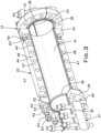
- FIG. 2 illustrates an end half segment 21, it being understood that an opposite half segment is identical to the illustrated half segment.
- the half segment 21 comprises a semi-cylindrical or arcuate axially extending wall 23 having longitudinal flanges 24 at its arcuate ends.
- the flanges 24 have faces 26 that when assembled with a respective opposing half segments are at or immediately adjacent a diametral plane of the segment 11.
- the flanges 24 have spaced through bolt holes 27 perpendicular to the faces 26.
- the half segment 21 has a radially extending semi-circular flange 28 with axially oriented through bolt holes 29.
- the longitudinal flanges 24 are spaced axially from the radial flange 28.
- the girder ring section 37 which conforms to the exterior of the pipe 13 being encased serves to axially retain the seal 36 against fluid pressure within the segment 11 developed by any fluid leakage from the pipe. Ends of the longitudinal seals 32 are in contact with the arcuate pipe seals 36 and with arcuate elastomeric seals 38, also of suitable material disposed between the radial flange 28 and an abutting flange of an intermediate segment 12.
- FIG. 3 illustrates a typical intermediate half segment 22.
- the half segment 22 includes an elongated semi-cylindrical shell 41 having a semi-circular radially extending flange 42 on each axial end.
- the flanges 42 have axially oriented through bolt holes 43.
- the longitudinal flanges are spaced from each of the respective radial flanges 42 and have through bolt holes 46 at diametral faces 47.
- Arcuate end faces of the shell 41 have longitudinal grooves 48 for reception of elastomeric seals 49.
- Axial outward faces 51 of the radial flanges 42 have concentric annular ribs 52.
- a concentric groove 53 in the rib 52 receives the arcuate elastomeric seal 38.
- Each end segment radial flange 28 has a similar rib and seal receiving groove. Ends of the longitudinal seals 49 are in contact with the arcuate seals 38.
- the fitting 10 can be installed over a pipe 13 starting at one end segment 11.
- the half segments 21 are positioned on opposite sides of the pipe 13 and are drawn tightly together with nuts 61 and bolts 62 assembled through aligned holes 27. This process causes the arcuate seals 36 to seal on the outside surface of the pipe 13.
- the pipe exterior Prior to assembly, the pipe exterior may be cleaned in the intended location of the seals 36 at both ends of the fitting 10.
- the end segment 11 is effectively fixed on the pipe.
- the longitudinal seals 32 adjacent the longitudinal flanges 24 are compressed and effect a seal therebetween and a seal with the arcuate seals 38.
- an intermediate segment 12 is assembled over the pipe 13 next to the inner end of the first installed end segment 11. This involves assembly and tightening of bolts 62 with nuts 61 in aligned flange holes 46.
- the angular orientation of the diametral plane between the half segments 22 is 90 degrees out of alignment with the diametral plane between the halves 21 of the end segment 11.
- the first intermediate segment is fixed to the end segment 11 by assembling bolts 63 in aligned radial flange holes 29, 43 and tightening nuts 64 on these bolts.
- Subsequent intermediate segments 12 are installed, typically one at a time, along the compromised portion of the pipe 13 in the same manner as described for the first intermediate segment 12.
- Each intermediate segment 12 preferably has its diametral plane of separation oriented so that it is 90 degrees from the plane of an abutting segment.
- the last installed end segment 11 is installed preferably again with its separation plane 90 degrees from that of the adjacent intermediate segment 12.
- the end segment radial flanges 28 should be abutted with the radial flanges 42 of the adjacent intermediate section 21 before the bolts 62 and nuts 61 are tightened and draw the seals 37 onto the pipe exterior.
- the intermediate segments 12 when installed are effectively free of restriction by engagement with the pipe 13.
- each groove carries its own seal.
- a single seal can be proportioned to seal in opposed grooves or only a single groove can be provided between mating faces.
Landscapes
- Engineering & Computer Science (AREA)
- General Engineering & Computer Science (AREA)
- Mechanical Engineering (AREA)
- Pipe Accessories (AREA)
- Branch Pipes, Bends, And The Like (AREA)
- Forms Removed On Construction Sites Or Auxiliary Members Thereof (AREA)
- Catching Or Destruction (AREA)
- Surgical Instruments (AREA)
Claims (4)
- Formteil zum Umschließen eines verlängerten Rohrstücks, das mehrere Segmente (11, 12) beinhaltet, die Ende an Ende zusammengefügt sind, um sich axial über das Rohrstück zu erstrecken, wobei jedes der Segmente (11, 12) von einem Paar zusammenpassender halbzylindrischer Abschnitte (21, 22) gebildet wird, wobei die Paare zusammenpassender Abschnitte (21, 22) bogenförmige Enden aufweisen, die sich in Längsrichtung erstreckende Gegen-Stirnflächen bilden, die in einer diametralen Ebene zusammenpassen, wobei die Längs-Gegen-Stirnflächen aufeinander abgedichtet sind, wobei die axialen Enden der Segmente (11, 12) in Umfangsrichtung aufeinander abgedichtet sind, wobei die Enden des Formteils Innendichtungen (32, 36) aufweisen, die angeordnet sind, um mit bzw. auf dem Äußeren des Rohrs in Kontakt zu sein und abzudichten, so dass der Zwischenraum zwischen den genannten Innendichtungen (36) in dem genannten Formteil geschlossen ist, dadurch gekennzeichnet, dass die Segmente (11, 12) radiale Endflansche (28, 42) mit axial ausgerichteten durchgehenden Schraubenlöchern (29, 43) aufweisen, wobei die Endflansche aneinander angrenzender Segmente durch gemeinsame Schrauben (63), durch die Schraubenlöcher (29, 43), aneinander befestigt sind, und dadurch, dass die radialen Endflansche (28, 42) aneinander angrenzender Segmente durch bogenförmige Zwischendichtungen (38) aufeinander abgedichtet sind.
- Formteil nach Anspruch 1, wobei die diametrale Ebene aneinander angrenzender Segmente (11, 12) um 90 Grad außer Flucht ist.
- Formteil nach Anspruch 1 oder Anspruch 2, wobei die Segmente (12) einwärts der Formteilenden durch Anlage an der Außenseite eines Rohrs, an dem das Formteil installiert ist, effektiv axial frei von Beschränkungen sind.
- Formteil nach einem der vorhergehenden Ansprüche, wobei die halbzylindrischen Abschnitte (21, 22) sich radial erstreckende Längsflansche (24, 44) in der oder angrenzend an die diametrale Ebene aufweisen, wobei die Flansche von zusammenpassenden Abschnitten eine Vielzahl fluchtender Schraubenlöcher (27) aufweisen, wobei die zusammenpassenden Abschnitte durch in den genannten fluchtenden Schraubenlöchern (27) montierten Schrauben (26) relativ zueinander in ihrer Lage gehalten werden.
Applications Claiming Priority (1)
| Application Number | Priority Date | Filing Date | Title |
|---|---|---|---|
| US15/872,262 US10816126B2 (en) | 2018-01-16 | 2018-01-16 | Modular split sleeve |
Publications (2)
| Publication Number | Publication Date |
|---|---|
| EP3511604A1 EP3511604A1 (de) | 2019-07-17 |
| EP3511604B1 true EP3511604B1 (de) | 2023-06-07 |
Family
ID=65033408
Family Applications (1)
| Application Number | Title | Priority Date | Filing Date |
|---|---|---|---|
| EP19151890.1A Active EP3511604B1 (de) | 2018-01-16 | 2019-01-15 | Modulare geschlitzte hülse |
Country Status (6)
| Country | Link |
|---|---|
| US (1) | US10816126B2 (de) |
| EP (1) | EP3511604B1 (de) |
| CN (1) | CN110043749B (de) |
| CA (1) | CA3030209C (de) |
| ES (1) | ES2953643T3 (de) |
| MX (1) | MX2019000687A (de) |
Families Citing this family (5)
| Publication number | Priority date | Publication date | Assignee | Title |
|---|---|---|---|---|
| US11415127B2 (en) * | 2018-04-27 | 2022-08-16 | Ameriforge Group Inc. | Well service pump system structural joint housing having a first connector and a second connector each including one or more lands and grooves that are configured to mate with corresponding lands and grooves in an end cylinder housing and a ram cylinder housing |
| US20210324685A1 (en) * | 2020-04-17 | 2021-10-21 | Chad Rudolph | Interlocking tubular with sectioned parts and related method |
| CN112431993A (zh) * | 2020-11-26 | 2021-03-02 | 安徽同发设备股份有限公司 | 哈夫节 |
| CN112728284A (zh) * | 2020-12-25 | 2021-04-30 | 安徽砼宇特构科技有限公司 | 一种检修用具有遇水膨胀胶的止水结构 |
| US12013059B2 (en) * | 2022-11-14 | 2024-06-18 | C. Allen Phillips | Pipe connection clamp |
Family Cites Families (34)
| Publication number | Priority date | Publication date | Assignee | Title |
|---|---|---|---|---|
| US427658A (en) * | 1890-05-13 | James c | ||
| US2899984A (en) * | 1959-08-18 | Gaffin | ||
| US640183A (en) * | 1899-04-07 | 1900-01-02 | Solomon R Dresser | Friction pipe-coupling. |
| US633607A (en) * | 1899-06-12 | 1899-09-26 | Ira J O'malley | Repair-clamp for pipes. |
| US631867A (en) * | 1899-06-16 | 1899-08-29 | Walter D Beaver | Leak-closer. |
| US672955A (en) | 1900-07-30 | 1901-04-30 | Charles Thomas Murrin | Pipe-patch attachment. |
| US732400A (en) * | 1903-04-10 | 1903-06-30 | Solomon R Dresser | Repair-sleeve for fluid-conducting pipes. |
| US1329522A (en) * | 1919-07-11 | 1920-02-03 | American Steam Conveyor Corp | Ash-conveyer |
| US1331988A (en) * | 1919-10-20 | 1920-02-24 | American Steam Conveyor Corp | Elbow for ash-conveyer systems |
| US1668855A (en) * | 1922-07-19 | 1928-05-08 | New York Engineering Company | Suction elevator |
| US1940729A (en) * | 1931-03-20 | 1933-12-26 | S R Dresser Mfg Co | Split sleeve for repairing pipe joints |
| US2402868A (en) * | 1943-08-27 | 1946-06-25 | Frank W Boyle | Packing for pipe joints |
| US2775469A (en) * | 1953-07-31 | 1956-12-25 | Mueller Co | Split pipe sleeve with means to prevent incorrect assembly |
| US3017204A (en) | 1959-01-12 | 1962-01-16 | Joseph B Smith | Split coupling |
| US3078108A (en) | 1959-08-05 | 1963-02-19 | Joseph B Smith | Split coupling |
| US3954288A (en) * | 1974-03-13 | 1976-05-04 | The Pipe Line Development Co. | Pipe fitting with self-testing seals and method |
| US4111234A (en) * | 1976-11-11 | 1978-09-05 | Wells James W | Repair device for pipes |
| US4096886A (en) | 1977-05-02 | 1978-06-27 | Ronald Albert Daspit | Clamp for repair of leaking underwater pipelines |
| US4652023A (en) * | 1984-02-13 | 1987-03-24 | Timmons Fred A | Repair coupler |
| US4747723A (en) * | 1987-02-06 | 1988-05-31 | Hasley George E | Universal joint coupling |
| US4840194A (en) * | 1988-01-14 | 1989-06-20 | Cooper Industries, Inc. | Explosion proof electrical conduit sealing fitting |
| JP3948818B2 (ja) * | 1998-03-27 | 2007-07-25 | 株式会社水道技術開発機構 | 管継手の固定構造 |
| US6305719B1 (en) * | 1998-10-30 | 2001-10-23 | Laurence S. Smith, Jr. | Pipe repair clamp |
| US6237640B1 (en) * | 2000-01-12 | 2001-05-29 | Nicor Technologies | Variable length pipe repair fitting |
| US6220302B1 (en) * | 2000-01-27 | 2001-04-24 | Jim B. Nolley | Chambered leak repairing device and method |
| CN200965135Y (zh) * | 2006-10-16 | 2007-10-24 | 青岛港(集团)有限公司 | 管道快速堵漏器 |
| GB0805342D0 (en) * | 2008-03-25 | 2008-04-30 | Flexlife Ltd | Metod and apparatus for repairing tubular members |
| US7900655B2 (en) * | 2008-07-18 | 2011-03-08 | Tdw Delaware, Inc. | Composite load transferring technique |
| US8210210B2 (en) | 2009-07-01 | 2012-07-03 | Colt Services, Lp | System and method for modular repair of pipe leaks |
| US8424925B2 (en) * | 2011-06-03 | 2013-04-23 | The Pipe Line Development Company | Split fitting for pipe |
| US8961017B2 (en) * | 2012-02-01 | 2015-02-24 | Mike Muilenburg | Split sleeve shaft repair |
| CN104676191B (zh) | 2015-01-30 | 2016-08-24 | 哈尔滨工程大学 | 海底管道卡箍修复连接器 |
| CN204554228U (zh) * | 2015-03-23 | 2015-08-12 | 安庆旭东工贸有限责任公司 | 一种长短可调式哈夫节 |
| JP6250215B1 (ja) * | 2017-06-19 | 2017-12-20 | 日鉄住金パイプライン&エンジニアリング株式会社 | 既設配管の更新方法 |
-
2018
- 2018-01-16 US US15/872,262 patent/US10816126B2/en active Active
-
2019
- 2019-01-14 CA CA3030209A patent/CA3030209C/en active Active
- 2019-01-15 ES ES19151890T patent/ES2953643T3/es active Active
- 2019-01-15 EP EP19151890.1A patent/EP3511604B1/de active Active
- 2019-01-16 MX MX2019000687A patent/MX2019000687A/es unknown
- 2019-01-16 CN CN201910039828.0A patent/CN110043749B/zh active Active
Also Published As
| Publication number | Publication date |
|---|---|
| CA3030209A1 (en) | 2019-07-16 |
| CN110043749B (zh) | 2022-03-29 |
| US10816126B2 (en) | 2020-10-27 |
| CN110043749A (zh) | 2019-07-23 |
| EP3511604A1 (de) | 2019-07-17 |
| MX2019000687A (es) | 2019-07-17 |
| US20190219213A1 (en) | 2019-07-18 |
| ES2953643T3 (es) | 2023-11-14 |
| CA3030209C (en) | 2023-01-24 |
Similar Documents
| Publication | Publication Date | Title |
|---|---|---|
| EP3511604B1 (de) | Modulare geschlitzte hülse | |
| US7219934B2 (en) | Pipe coupling | |
| EP1816325B1 (de) | Abgasrohrverbindung mit Einsatz | |
| JPH06235492A (ja) | プラスチックライニングを有する二重収容配管系統 | |
| US20170314723A1 (en) | Clamp for repair of pipe couplings | |
| US20180156367A1 (en) | Encapsulation sleeve gasket assembly with removable inner layer | |
| EP2066950B1 (de) | Kupplung für einen bänder-schlauch | |
| US4268070A (en) | Orifice flange clamp | |
| US11614195B2 (en) | Extended range encapsulation shell | |
| US5085471A (en) | Double containment pipe joint assembly | |
| US5171042A (en) | Spigot joint for lined metallic pipes particularly for fluids | |
| US10364929B2 (en) | Pipe coupling encapsulation assembly | |
| GB2197420A (en) | Pipe repair collar | |
| US5360238A (en) | Pipe couplings | |
| EP2957813B1 (de) | Flanschanschlussstück | |
| CN109455524B (zh) | 一种管道伸缩节装置及具有该装置的气动管道传输系统 | |
| US4725082A (en) | Coupling | |
| EP4127536B1 (de) | Verbinderanordnung | |
| JP2019178787A (ja) | 伸縮管継手構造 | |
| NO171613B (no) | Koblingssegment | |
| AU2003203862A1 (en) | Pipe coupling |
Legal Events
| Date | Code | Title | Description |
|---|---|---|---|
| PUAI | Public reference made under article 153(3) epc to a published international application that has entered the european phase |
Free format text: ORIGINAL CODE: 0009012 |
|
| STAA | Information on the status of an ep patent application or granted ep patent |
Free format text: STATUS: THE APPLICATION HAS BEEN PUBLISHED |
|
| AK | Designated contracting states |
Kind code of ref document: A1 Designated state(s): AL AT BE BG CH CY CZ DE DK EE ES FI FR GB GR HR HU IE IS IT LI LT LU LV MC MK MT NL NO PL PT RO RS SE SI SK SM TR |
|
| AX | Request for extension of the european patent |
Extension state: BA ME |
|
| STAA | Information on the status of an ep patent application or granted ep patent |
Free format text: STATUS: REQUEST FOR EXAMINATION WAS MADE |
|
| 17P | Request for examination filed |
Effective date: 20200113 |
|
| RBV | Designated contracting states (corrected) |
Designated state(s): AL AT BE BG CH CY CZ DE DK EE ES FI FR GB GR HR HU IE IS IT LI LT LU LV MC MK MT NL NO PL PT RO RS SE SI SK SM TR |
|
| STAA | Information on the status of an ep patent application or granted ep patent |
Free format text: STATUS: EXAMINATION IS IN PROGRESS |
|
| 17Q | First examination report despatched |
Effective date: 20210201 |
|
| GRAP | Despatch of communication of intention to grant a patent |
Free format text: ORIGINAL CODE: EPIDOSNIGR1 |
|
| STAA | Information on the status of an ep patent application or granted ep patent |
Free format text: STATUS: GRANT OF PATENT IS INTENDED |
|
| RIC1 | Information provided on ipc code assigned before grant |
Ipc: F16L 9/22 20060101ALN20221007BHEP Ipc: F16L 55/172 20060101AFI20221007BHEP |
|
| INTG | Intention to grant announced |
Effective date: 20221028 |
|
| GRAS | Grant fee paid |
Free format text: ORIGINAL CODE: EPIDOSNIGR3 |
|
| GRAJ | Information related to disapproval of communication of intention to grant by the applicant or resumption of examination proceedings by the epo deleted |
Free format text: ORIGINAL CODE: EPIDOSDIGR1 |
|
| GRAL | Information related to payment of fee for publishing/printing deleted |
Free format text: ORIGINAL CODE: EPIDOSDIGR3 |
|
| STAA | Information on the status of an ep patent application or granted ep patent |
Free format text: STATUS: EXAMINATION IS IN PROGRESS |
|
| RAP3 | Party data changed (applicant data changed or rights of an application transferred) |
Owner name: THE PIPE LINE DEVELOPMENT COMPANY |
|
| GRAP | Despatch of communication of intention to grant a patent |
Free format text: ORIGINAL CODE: EPIDOSNIGR1 |
|
| STAA | Information on the status of an ep patent application or granted ep patent |
Free format text: STATUS: GRANT OF PATENT IS INTENDED |
|
| INTC | Intention to grant announced (deleted) | ||
| INTG | Intention to grant announced |
Effective date: 20230323 |
|
| RIC1 | Information provided on ipc code assigned before grant |
Ipc: F16L 9/22 20060101ALN20230310BHEP Ipc: F16L 55/172 20060101AFI20230310BHEP |
|
| GRAA | (expected) grant |
Free format text: ORIGINAL CODE: 0009210 |
|
| STAA | Information on the status of an ep patent application or granted ep patent |
Free format text: STATUS: THE PATENT HAS BEEN GRANTED |
|
| AK | Designated contracting states |
Kind code of ref document: B1 Designated state(s): AL AT BE BG CH CY CZ DE DK EE ES FI FR GB GR HR HU IE IS IT LI LT LU LV MC MK MT NL NO PL PT RO RS SE SI SK SM TR |
|
| REG | Reference to a national code |
Ref country code: GB Ref legal event code: FG4D |
|
| REG | Reference to a national code |
Ref country code: CH Ref legal event code: EP Ref country code: AT Ref legal event code: REF Ref document number: 1576043 Country of ref document: AT Kind code of ref document: T Effective date: 20230615 |
|
| REG | Reference to a national code |
Ref country code: DE Ref legal event code: R096 Ref document number: 602019029692 Country of ref document: DE |
|
| REG | Reference to a national code |
Ref country code: LT Ref legal event code: MG9D |
|
| REG | Reference to a national code |
Ref country code: NO Ref legal event code: T2 Effective date: 20230607 |
|
| REG | Reference to a national code |
Ref country code: NL Ref legal event code: MP Effective date: 20230607 |
|
| PG25 | Lapsed in a contracting state [announced via postgrant information from national office to epo] |
Ref country code: SE Free format text: LAPSE BECAUSE OF FAILURE TO SUBMIT A TRANSLATION OF THE DESCRIPTION OR TO PAY THE FEE WITHIN THE PRESCRIBED TIME-LIMIT Effective date: 20230607 |
|
| REG | Reference to a national code |
Ref country code: ES Ref legal event code: FG2A Ref document number: 2953643 Country of ref document: ES Kind code of ref document: T3 Effective date: 20231114 |
|
| REG | Reference to a national code |
Ref country code: AT Ref legal event code: MK05 Ref document number: 1576043 Country of ref document: AT Kind code of ref document: T Effective date: 20230607 |
|
| PG25 | Lapsed in a contracting state [announced via postgrant information from national office to epo] |
Ref country code: RS Free format text: LAPSE BECAUSE OF FAILURE TO SUBMIT A TRANSLATION OF THE DESCRIPTION OR TO PAY THE FEE WITHIN THE PRESCRIBED TIME-LIMIT Effective date: 20230607 Ref country code: NL Free format text: LAPSE BECAUSE OF FAILURE TO SUBMIT A TRANSLATION OF THE DESCRIPTION OR TO PAY THE FEE WITHIN THE PRESCRIBED TIME-LIMIT Effective date: 20230607 Ref country code: LV Free format text: LAPSE BECAUSE OF FAILURE TO SUBMIT A TRANSLATION OF THE DESCRIPTION OR TO PAY THE FEE WITHIN THE PRESCRIBED TIME-LIMIT Effective date: 20230607 Ref country code: LT Free format text: LAPSE BECAUSE OF FAILURE TO SUBMIT A TRANSLATION OF THE DESCRIPTION OR TO PAY THE FEE WITHIN THE PRESCRIBED TIME-LIMIT Effective date: 20230607 Ref country code: HR Free format text: LAPSE BECAUSE OF FAILURE TO SUBMIT A TRANSLATION OF THE DESCRIPTION OR TO PAY THE FEE WITHIN THE PRESCRIBED TIME-LIMIT Effective date: 20230607 Ref country code: GR Free format text: LAPSE BECAUSE OF FAILURE TO SUBMIT A TRANSLATION OF THE DESCRIPTION OR TO PAY THE FEE WITHIN THE PRESCRIBED TIME-LIMIT Effective date: 20230908 |
|
| PG25 | Lapsed in a contracting state [announced via postgrant information from national office to epo] |
Ref country code: FI Free format text: LAPSE BECAUSE OF FAILURE TO SUBMIT A TRANSLATION OF THE DESCRIPTION OR TO PAY THE FEE WITHIN THE PRESCRIBED TIME-LIMIT Effective date: 20230607 |
|
| PG25 | Lapsed in a contracting state [announced via postgrant information from national office to epo] |
Ref country code: SK Free format text: LAPSE BECAUSE OF FAILURE TO SUBMIT A TRANSLATION OF THE DESCRIPTION OR TO PAY THE FEE WITHIN THE PRESCRIBED TIME-LIMIT Effective date: 20230607 |
|
| PG25 | Lapsed in a contracting state [announced via postgrant information from national office to epo] |
Ref country code: IS Free format text: LAPSE BECAUSE OF FAILURE TO SUBMIT A TRANSLATION OF THE DESCRIPTION OR TO PAY THE FEE WITHIN THE PRESCRIBED TIME-LIMIT Effective date: 20231007 |
|
| PG25 | Lapsed in a contracting state [announced via postgrant information from national office to epo] |
Ref country code: SM Free format text: LAPSE BECAUSE OF FAILURE TO SUBMIT A TRANSLATION OF THE DESCRIPTION OR TO PAY THE FEE WITHIN THE PRESCRIBED TIME-LIMIT Effective date: 20230607 Ref country code: SK Free format text: LAPSE BECAUSE OF FAILURE TO SUBMIT A TRANSLATION OF THE DESCRIPTION OR TO PAY THE FEE WITHIN THE PRESCRIBED TIME-LIMIT Effective date: 20230607 Ref country code: RO Free format text: LAPSE BECAUSE OF FAILURE TO SUBMIT A TRANSLATION OF THE DESCRIPTION OR TO PAY THE FEE WITHIN THE PRESCRIBED TIME-LIMIT Effective date: 20230607 Ref country code: PT Free format text: LAPSE BECAUSE OF FAILURE TO SUBMIT A TRANSLATION OF THE DESCRIPTION OR TO PAY THE FEE WITHIN THE PRESCRIBED TIME-LIMIT Effective date: 20231009 Ref country code: IS Free format text: LAPSE BECAUSE OF FAILURE TO SUBMIT A TRANSLATION OF THE DESCRIPTION OR TO PAY THE FEE WITHIN THE PRESCRIBED TIME-LIMIT Effective date: 20231007 Ref country code: EE Free format text: LAPSE BECAUSE OF FAILURE TO SUBMIT A TRANSLATION OF THE DESCRIPTION OR TO PAY THE FEE WITHIN THE PRESCRIBED TIME-LIMIT Effective date: 20230607 Ref country code: CZ Free format text: LAPSE BECAUSE OF FAILURE TO SUBMIT A TRANSLATION OF THE DESCRIPTION OR TO PAY THE FEE WITHIN THE PRESCRIBED TIME-LIMIT Effective date: 20230607 Ref country code: AT Free format text: LAPSE BECAUSE OF FAILURE TO SUBMIT A TRANSLATION OF THE DESCRIPTION OR TO PAY THE FEE WITHIN THE PRESCRIBED TIME-LIMIT Effective date: 20230607 |
|
| PG25 | Lapsed in a contracting state [announced via postgrant information from national office to epo] |
Ref country code: PL Free format text: LAPSE BECAUSE OF FAILURE TO SUBMIT A TRANSLATION OF THE DESCRIPTION OR TO PAY THE FEE WITHIN THE PRESCRIBED TIME-LIMIT Effective date: 20230607 |
|
| REG | Reference to a national code |
Ref country code: DE Ref legal event code: R097 Ref document number: 602019029692 Country of ref document: DE |
|
| PLBE | No opposition filed within time limit |
Free format text: ORIGINAL CODE: 0009261 |
|
| STAA | Information on the status of an ep patent application or granted ep patent |
Free format text: STATUS: NO OPPOSITION FILED WITHIN TIME LIMIT |
|
| PGFP | Annual fee paid to national office [announced via postgrant information from national office to epo] |
Ref country code: IE Payment date: 20240131 Year of fee payment: 6 |
|
| PG25 | Lapsed in a contracting state [announced via postgrant information from national office to epo] |
Ref country code: DK Free format text: LAPSE BECAUSE OF FAILURE TO SUBMIT A TRANSLATION OF THE DESCRIPTION OR TO PAY THE FEE WITHIN THE PRESCRIBED TIME-LIMIT Effective date: 20230607 |
|
| PGFP | Annual fee paid to national office [announced via postgrant information from national office to epo] |
Ref country code: GB Payment date: 20240131 Year of fee payment: 6 |
|
| PG25 | Lapsed in a contracting state [announced via postgrant information from national office to epo] |
Ref country code: SI Free format text: LAPSE BECAUSE OF FAILURE TO SUBMIT A TRANSLATION OF THE DESCRIPTION OR TO PAY THE FEE WITHIN THE PRESCRIBED TIME-LIMIT Effective date: 20230607 |
|
| 26N | No opposition filed |
Effective date: 20240308 |
|
| PG25 | Lapsed in a contracting state [announced via postgrant information from national office to epo] |
Ref country code: SI Free format text: LAPSE BECAUSE OF FAILURE TO SUBMIT A TRANSLATION OF THE DESCRIPTION OR TO PAY THE FEE WITHIN THE PRESCRIBED TIME-LIMIT Effective date: 20230607 |
|
| PGFP | Annual fee paid to national office [announced via postgrant information from national office to epo] |
Ref country code: TR Payment date: 20240108 Year of fee payment: 6 Ref country code: NO Payment date: 20240130 Year of fee payment: 6 Ref country code: IT Payment date: 20240130 Year of fee payment: 6 Ref country code: FR Payment date: 20240130 Year of fee payment: 6 |
|
| REG | Reference to a national code |
Ref country code: DE Ref legal event code: R119 Ref document number: 602019029692 Country of ref document: DE |
|
| PG25 | Lapsed in a contracting state [announced via postgrant information from national office to epo] |
Ref country code: MC Free format text: LAPSE BECAUSE OF FAILURE TO SUBMIT A TRANSLATION OF THE DESCRIPTION OR TO PAY THE FEE WITHIN THE PRESCRIBED TIME-LIMIT Effective date: 20230607 |
|
| PG25 | Lapsed in a contracting state [announced via postgrant information from national office to epo] |
Ref country code: MC Free format text: LAPSE BECAUSE OF FAILURE TO SUBMIT A TRANSLATION OF THE DESCRIPTION OR TO PAY THE FEE WITHIN THE PRESCRIBED TIME-LIMIT Effective date: 20230607 |
|
| REG | Reference to a national code |
Ref country code: CH Ref legal event code: PL |
|
| PG25 | Lapsed in a contracting state [announced via postgrant information from national office to epo] |
Ref country code: LU Free format text: LAPSE BECAUSE OF NON-PAYMENT OF DUE FEES Effective date: 20240115 |