EP3511552B1 - Carburator for the combustion engine in a hand-held work device, combustion engine with a carburator and method for operating a combustion engine - Google Patents
Carburator for the combustion engine in a hand-held work device, combustion engine with a carburator and method for operating a combustion engine Download PDFInfo
- Publication number
- EP3511552B1 EP3511552B1 EP19150488.5A EP19150488A EP3511552B1 EP 3511552 B1 EP3511552 B1 EP 3511552B1 EP 19150488 A EP19150488 A EP 19150488A EP 3511552 B1 EP3511552 B1 EP 3511552B1
- Authority
- EP
- European Patent Office
- Prior art keywords
- carburettor
- roller
- carburetor
- combustion engine
- control contour
- Prior art date
- Legal status (The legal status is an assumption and is not a legal conclusion. Google has not performed a legal analysis and makes no representation as to the accuracy of the status listed.)
- Active
Links
Images


Classifications
-
- F—MECHANICAL ENGINEERING; LIGHTING; HEATING; WEAPONS; BLASTING
- F02—COMBUSTION ENGINES; HOT-GAS OR COMBUSTION-PRODUCT ENGINE PLANTS
- F02M—SUPPLYING COMBUSTION ENGINES IN GENERAL WITH COMBUSTIBLE MIXTURES OR CONSTITUENTS THEREOF
- F02M1/00—Carburettors with means for facilitating engine's starting or its idling below operational temperatures
- F02M1/02—Carburettors with means for facilitating engine's starting or its idling below operational temperatures the means to facilitate starting or idling being chokes for enriching fuel-air mixture
-
- F—MECHANICAL ENGINEERING; LIGHTING; HEATING; WEAPONS; BLASTING
- F02—COMBUSTION ENGINES; HOT-GAS OR COMBUSTION-PRODUCT ENGINE PLANTS
- F02B—INTERNAL-COMBUSTION PISTON ENGINES; COMBUSTION ENGINES IN GENERAL
- F02B33/00—Engines characterised by provision of pumps for charging or scavenging
- F02B33/02—Engines with reciprocating-piston pumps; Engines with crankcase pumps
- F02B33/04—Engines with reciprocating-piston pumps; Engines with crankcase pumps with simple crankcase pumps, i.e. with the rear face of a non-stepped working piston acting as sole pumping member in co-operation with the crankcase
-
- F—MECHANICAL ENGINEERING; LIGHTING; HEATING; WEAPONS; BLASTING
- F02—COMBUSTION ENGINES; HOT-GAS OR COMBUSTION-PRODUCT ENGINE PLANTS
- F02B—INTERNAL-COMBUSTION PISTON ENGINES; COMBUSTION ENGINES IN GENERAL
- F02B63/00—Adaptations of engines for driving pumps, hand-held tools or electric generators; Portable combinations of engines with engine-driven devices
- F02B63/02—Adaptations of engines for driving pumps, hand-held tools or electric generators; Portable combinations of engines with engine-driven devices for hand-held tools
-
- F—MECHANICAL ENGINEERING; LIGHTING; HEATING; WEAPONS; BLASTING
- F02—COMBUSTION ENGINES; HOT-GAS OR COMBUSTION-PRODUCT ENGINE PLANTS
- F02D—CONTROLLING COMBUSTION ENGINES
- F02D35/00—Controlling engines, dependent on conditions exterior or interior to engines, not otherwise provided for
- F02D35/0015—Controlling engines, dependent on conditions exterior or interior to engines, not otherwise provided for using exhaust gas sensors
- F02D35/0046—Controlling fuel supply
- F02D35/0053—Controlling fuel supply by means of a carburettor
- F02D35/0084—Controlling fuel supply by means of a carburettor using two barrel carburettors
-
- F—MECHANICAL ENGINEERING; LIGHTING; HEATING; WEAPONS; BLASTING
- F02—COMBUSTION ENGINES; HOT-GAS OR COMBUSTION-PRODUCT ENGINE PLANTS
- F02D—CONTROLLING COMBUSTION ENGINES
- F02D9/00—Controlling engines by throttling air or fuel-and-air induction conduits or exhaust conduits
- F02D9/08—Throttle valves specially adapted therefor; Arrangements of such valves in conduits
- F02D9/12—Throttle valves specially adapted therefor; Arrangements of such valves in conduits having slidably-mounted valve members; having valve members movable longitudinally of conduit
- F02D9/16—Throttle valves specially adapted therefor; Arrangements of such valves in conduits having slidably-mounted valve members; having valve members movable longitudinally of conduit the members being rotatable
-
- F—MECHANICAL ENGINEERING; LIGHTING; HEATING; WEAPONS; BLASTING
- F02—COMBUSTION ENGINES; HOT-GAS OR COMBUSTION-PRODUCT ENGINE PLANTS
- F02M—SUPPLYING COMBUSTION ENGINES IN GENERAL WITH COMBUSTIBLE MIXTURES OR CONSTITUENTS THEREOF
- F02M17/00—Carburettors having pertinent characteristics not provided for in, or of interest apart from, the apparatus of preceding main groups F02M1/00 - F02M15/00
- F02M17/02—Floatless carburettors
-
- F—MECHANICAL ENGINEERING; LIGHTING; HEATING; WEAPONS; BLASTING
- F02—COMBUSTION ENGINES; HOT-GAS OR COMBUSTION-PRODUCT ENGINE PLANTS
- F02M—SUPPLYING COMBUSTION ENGINES IN GENERAL WITH COMBUSTIBLE MIXTURES OR CONSTITUENTS THEREOF
- F02M35/00—Combustion-air cleaners, air intakes, intake silencers, or induction systems specially adapted for, or arranged on, internal-combustion engines
- F02M35/10—Air intakes; Induction systems
- F02M35/1015—Air intakes; Induction systems characterised by the engine type
- F02M35/1017—Small engines, e.g. for handheld tools, or model engines; Single cylinder engines
-
- F—MECHANICAL ENGINEERING; LIGHTING; HEATING; WEAPONS; BLASTING
- F02—COMBUSTION ENGINES; HOT-GAS OR COMBUSTION-PRODUCT ENGINE PLANTS
- F02M—SUPPLYING COMBUSTION ENGINES IN GENERAL WITH COMBUSTIBLE MIXTURES OR CONSTITUENTS THEREOF
- F02M35/00—Combustion-air cleaners, air intakes, intake silencers, or induction systems specially adapted for, or arranged on, internal-combustion engines
- F02M35/10—Air intakes; Induction systems
- F02M35/1015—Air intakes; Induction systems characterised by the engine type
- F02M35/10196—Carburetted engines
-
- F—MECHANICAL ENGINEERING; LIGHTING; HEATING; WEAPONS; BLASTING
- F02—COMBUSTION ENGINES; HOT-GAS OR COMBUSTION-PRODUCT ENGINE PLANTS
- F02M—SUPPLYING COMBUSTION ENGINES IN GENERAL WITH COMBUSTIBLE MIXTURES OR CONSTITUENTS THEREOF
- F02M9/00—Carburettors having air or fuel-air mixture passage throttling valves other than of butterfly type; Carburettors having fuel-air mixing chambers of variable shape or position
- F02M9/08—Carburettors having air or fuel-air mixture passage throttling valves other than of butterfly type; Carburettors having fuel-air mixing chambers of variable shape or position having throttling valves rotatably mounted in the passage
-
- F—MECHANICAL ENGINEERING; LIGHTING; HEATING; WEAPONS; BLASTING
- F02—COMBUSTION ENGINES; HOT-GAS OR COMBUSTION-PRODUCT ENGINE PLANTS
- F02B—INTERNAL-COMBUSTION PISTON ENGINES; COMBUSTION ENGINES IN GENERAL
- F02B75/00—Other engines
- F02B75/02—Engines characterised by their cycles, e.g. six-stroke
- F02B2075/022—Engines characterised by their cycles, e.g. six-stroke having less than six strokes per cycle
- F02B2075/025—Engines characterised by their cycles, e.g. six-stroke having less than six strokes per cycle two
-
- F—MECHANICAL ENGINEERING; LIGHTING; HEATING; WEAPONS; BLASTING
- F02—COMBUSTION ENGINES; HOT-GAS OR COMBUSTION-PRODUCT ENGINE PLANTS
- F02D—CONTROLLING COMBUSTION ENGINES
- F02D2200/00—Input parameters for engine control
- F02D2200/02—Input parameters for engine control the parameters being related to the engine
- F02D2200/04—Engine intake system parameters
- F02D2200/0404—Throttle position
-
- F—MECHANICAL ENGINEERING; LIGHTING; HEATING; WEAPONS; BLASTING
- F02—COMBUSTION ENGINES; HOT-GAS OR COMBUSTION-PRODUCT ENGINE PLANTS
- F02M—SUPPLYING COMBUSTION ENGINES IN GENERAL WITH COMBUSTIBLE MIXTURES OR CONSTITUENTS THEREOF
- F02M35/00—Combustion-air cleaners, air intakes, intake silencers, or induction systems specially adapted for, or arranged on, internal-combustion engines
- F02M35/10—Air intakes; Induction systems
- F02M35/1015—Air intakes; Induction systems characterised by the engine type
- F02M35/1019—Two-stroke engines; Reverse-flow scavenged or cross scavenged engines
Definitions
- the invention relates to a carburetor for the internal combustion engine in a hand-held tool of the type specified in the preamble of claim 1, an internal combustion engine with a carburetor and a method for operating an internal combustion engine.
- a carburetor with a carburetor roller is known.
- a rotary position transmitter is arranged at one end of the carburetor roller.
- the DE 10 2013 009 668 A1 discloses an internal combustion engine having a starting device.
- the starting device comprises a guide surface that slides on a gate.
- a carburetor roller is moved in the axial direction and the free flow cross-section of an annular gap which is formed between a fuel opening and an adjusting needle held on the carburetor roller is thereby adjusted.
- the detection device comprises a control contour and a detection means that interacts with the control contour and that the control contour is formed directly on the carburetor roller.
- the arrangement of the control contour on the carburetor cylinder allows tolerances between the position of the control contour and the position of the carburetor cylinder to be minimized.
- a control contour can be introduced into the carburetor cylinder in a simple manner during the manufacture of the carburetor cylinder.
- a control contour is a contour to be mechanically scanned, for example an elevation or depression on the outer circumference of the carburetor roller.
- a control contour can be easily produced by machining the carburetor roller.
- control contour has different distances from the pivot axis of the carburetor roller in different circumferential sections of the carburetor roller, which are detected by the detection means. It is preferably provided that the detection means scans the control contour.
- the detection device is designed to generate an electrical signal.
- the signal generated by the detection device can in particular be read out in an evaluation unit and can advantageously be used to control a fuel supply device.
- the evaluation unit can be, for example, a control unit of an internal combustion engine.
- the control contour is preferably arranged directly on the carburetor roller.
- the control contour is arranged in particular on an upper side of the carburetor roller.
- the control contour is in particular formed in one piece with that part of the carburetor roller which has the at least one channel running transversely to the pivot axis. Thereby tolerances between the at least one channel and the control contour can be minimized.
- the carburetor roller is advantageously designed in several parts.
- a first part of the carburetor roller advantageously has the control contour and a second part has the at least one channel.
- the first part and the second part are advantageously firmly connected to one another, in particular by welding, gluing or the like.
- the two parts are in particular connected to one another in a materially bonded manner.
- the at least two parts of the carburetor roller can advantageously consist of different materials.
- the control contour can be formed in a part from wear-resistant material, for example a plastic
- the at least one channel can be formed in a fuel-resistant material, for example metal or another plastic.
- the two parts can be precisely positioned to one another during production before the parts are firmly connected to one another, so that small tolerances can be maintained.
- the control contour is advantageously arranged on the roller body.
- the control contour can be designed with a comparatively large distance from the pivot axis of the roller body. This minimizes tolerances when detecting the rotary position of the carburetor drum.
- the control contour is preferably arranged in the region of the roller body which has the largest diameter.
- the control contour is advantageously formed in the roller body of the carburetor roller.
- the roller body of the carburetor roller is designed in one piece in an advantageous design. In an advantageous alternative design, the roller body is made up of two parts that are firmly connected to one another.
- the control contour preferably comprises at least one depression on the circumference of the carburetor roller.
- the control contour advantageously comprises at least one depression in the circumference of the roller body of the carburetor roller.
- the control contour comprises a first depression which is assigned to the idle.
- the control contour comprises a first recess, which is assigned to idling, and a second recess, which is assigned to full load.
- the idle position can therefore be determined via the control contour.
- the idling position and the full load position can be determined particularly advantageously via the control contour.
- the partial load range that exists between the idle position and the full load position can be determined by a signal that deviates from the idle position and the full load position.
- the position of all positions of the roller body that are important for controlling the internal combustion engine can be detected via two switching states of the detection device.
- the distinction between the idle position and the full load position can be achieved by different signals in the idle position and the full load position, for example by means of different depths for the idle position and the full load position.
- the detection device detects the same signal in the idle position and the full load position, and the distinction between the idle position and the full load position is made using further information, in particular on the basis of a speed of the internal combustion engine.
- the scanning of the control contour has an advantageous effect on an operating element, for example a throttle lever, via which the operator adjusts the carburetor roller.
- an operating element for example a throttle lever
- at least one recess has a base that delimits the recess in the radial direction.
- the bottom advantageously merges into the outer circumferential surface of the carburetor roller with a slope on at least one side lying in the circumferential direction.
- the inclination of the incline is advantageously chosen so that the rotational position of the carburetor roller can be detected with sufficient accuracy, but at the same time low forces from the incline be exercised on the throttle, which are advantageously not or hardly noticed by the operator.
- the bottom delimits the depression in a radially inner direction.
- the bottom of the recess merges with the incline into a curved surface segment.
- the surface segment is advantageously curved with one or more radii around the pivot axis of the roller body.
- the radii advantageously differ from the distance between the bottom of the recess and the pivot axis, so that the surface segment and the bottom of the recess are designed with different radii.
- a further switching state of the detection device can be achieved via the curved surface segment. In particular, this allows further rotational positions of the roller body to be recorded.
- the curved surface segment can be a surface segment whose radius is smaller than that of the outer circumferential surface of the carburetor roller in order to enable the arrangement in a smaller installation space.
- the radius of the curved surface segment is greater than that of the outer circumferential surface.
- the bottom of the recess advantageously delimits the recess on the side lying radially inward relative to the pivot axis.
- the detection means rests on the control contour radially outside the control contour in relation to the pivot axis.
- the detection means is advantageously spring-loaded radially inward by a return spring with respect to the pivot axis.
- the detection device advantageously comprises a switch which is actuated as a function of the position of the detection means. At least two switching states can be detected in a simple manner via a switch. An electrical signal generated by a switch can be further processed electronically in a simple manner, in particular by an electronic control device.
- the detection means is preferably formed on a pivot lever which is mounted on the carburetor housing so as to be pivotable about a second pivot axis lying parallel to the pivot axis of the carburetor drum.
- the pivot lever is connected to ground via the return spring.
- the return spring is therefore a contact spring, via which an electrical contact to ground is established. This results in a simple structure with few components. However, it can also be provided that different spring elements are used to establish the ground contact and to preload the pivot lever into its radially inner position.
- a fuel valve is advantageously provided, via which fuel is fed into the intake duct.
- the fuel valve can be activated and the required amount of fuel can be precisely metered.
- the internal combustion engine has a control device which is connected to the detection device and the fuel valve for feeding fuel into the intake duct.
- a method for operating an internal combustion engine advantageously provides that the control device controls the amount of fuel supplied as a function of the rotational position of the carburetor drum detected by the detection device. This enables precise metering of fuel, in particular if the entire amount of fuel supplied to the intake duct is metered via a single fuel valve. Provision can advantageously be made to influence the control of the ignition of the internal combustion engine by means of the detection of at least one rotational position of the carburetor drum.
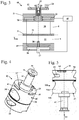
- Fig. 1 shows a brushcutter 37 as an exemplary embodiment of a hand-held tool.
- the brushcutter 37 has a housing 38 which is connected to a tool head 69 via a guide tube 39.
- a tool 40 in the exemplary embodiment a cutting knife, is mounted on the tool head 69 so as to be rotatable about an axis of rotation 44.
- the tool 40 is arranged in the housing 38, in Fig. 2 internal combustion engine 1 shown schematically.
- a starter device is provided, the starter handle 43 of which protrudes from the housing 38, as Fig. 1 shows.
- handles 41 are provided which are fixed to the guide tube 39 via a bracket.
- At least one operating element 42 for controlling the internal combustion engine 1 is arranged on one of the handles 41.
- Fig. 2 shows the structure of the internal combustion engine 1 schematically.
- the internal combustion engine 1 is a two-stroke engine working with a flushing reservoir.
- Another design of the internal combustion engine 1 for example a design as However, a four-stroke engine, in particular as a mixture-lubricated four-stroke engine, can be advantageous.
- the internal combustion engine 1 has a cylinder 2 in which a combustion chamber 3 is formed.
- the combustion chamber 3 is delimited by a piston 5 mounted to and fro in the cylinder 2, which piston drives a crankshaft 7 rotatably mounted in a crankcase 4 via a connecting rod 6.
- the internal combustion engine 1 comprises an air filter 17, via which combustion air is sucked in during operation.
- the air filter 17 is connected to an air inlet 10 and a mixture inlet 11 on the cylinder 2 via an intake duct 26. Intake combustion air and fuel / air mixture flow in a flow direction 36 through the intake channel 26.
- the intake channel 26 is separated by a partition 31 into the first supply channel 8 for air and the second supply channel 9 for mixture.
- the combustion air is drawn in through a first supply duct 8, which is provided for supplying air, to at least one air inlet 10 on the cylinder 2.
- Combustion air is also drawn in via a second supply channel 9, which is provided for supplying the fuel / air mixture, to a mixture inlet 11.
- the internal combustion engine 1 has transfer passages 13 close to the outlet and transfer passages 14 close to the inlet, which open with transfer windows 15 at the cylinder bore.
- the overflow channels 13 and 14 connect in the area of in Fig. 2
- the bottom dead center of the piston 5 shown is the interior of the crankcase 4 with the combustion chamber 3.
- the mixture inlet 11 and the air inlet 10 are controlled by the piston skirt of the piston 5.
- the internal combustion engine 1 of the embodiment is a slot-type engine.
- the mixture inlet 11 is connected to the interior of the crankcase 4 in the area of the top dead center of the piston 5.
- the air inlet 10 opens into a region of the piston 5 in which a piston pocket 12 of the piston 5 moves.
- the piston pocket 12 connects the air inlet 10 in the area of the top dead center of the piston 5 with the overflow windows 15 of the overflow channels 13 near the outlet and the overflow channels 14 remote from the outlet.
- the illustration in FIG Fig. 2 is only schematic.
- a carburetor 18 is provided for supplying fuel.
- the carburetor 18 has a carburetor roller 20.
- the carburetor roller 20 is rotatably mounted to control the amount of combustion air supplied.
- a first channel 34 is formed, which forms an air channel section, and a second channel 33, which forms a mixture channel section.
- a second channel 33 which forms a mixture channel section.
- the fuel / air mixture is sucked from the second supply channel 9 via the mixture inlet 11 into the interior of the crankcase 4.
- the piston pockets 12 connect the at least one air inlet 10 to the overflow windows 15
- fuel-free or low-fuel combustion air is sucked from the first supply duct 8 through the overflow windows 15 into the overflow ducts 13 and 14.
- the fuel / air mixture in the interior of the crankcase 4 is compressed in the interior of the crankcase 4 during the subsequent downward stroke, that is, the movement of the piston 5 from the combustion chamber 3 in the direction of the crankcase 4.
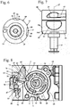
- Fig. 3 shows the structure of the carburetor 18 in detail.
- the carburetor 18 has a carburetor housing 19 which is closed by a cover 21.
- the carburetor roller 20 is mounted pivotably about a pivot axis 35.
- An actuating lever 23 is fixed to the carburetor drum 20, on which the operating element 42 ( Fig. 1 ) of the implement is effective.
- the operating element 42 is advantageously connected to an actuating pin 24 fixed on the actuating lever 23 via a Bowden cable or another transmission element. If the operator actuates the operating element 42, the carburetor drum 20 swivels in the carburetor housing 19 about the swivel axis 35.
- a fuel opening 28, which opens into the second channel 33 of the carburetor roller 20, is provided for the supply of fuel.
- the fuel opening 28 is connected to a fuel chamber 30 via a fuel valve 27.
- the fuel valve 27 is preferably designed as an electromagnetic valve and controls the entire amount of fuel supplied into the channel 33 via the fuel opening 28.
- the fuel opening 28 is advantageously the only fuel opening opening into the carburetor cylinder 20.
- the fuel valve 27 is activated by a control device 45.
- a switch 22 is provided in the exemplary embodiment, which is shown in FIG Fig. 3 is shown schematically and its structure is explained in more detail below.
- the switch 22 is connected to the control device 45.
- a control needle protrudes into the fuel opening 28 to control the amount of fuel supplied and the size of an annular gap formed between the control needle and the fuel opening changes as a function of the rotational position of the carburetor roller 20.
- the Figures 4 to 6 show the design of the carburetor roller 20 in detail.
- the carburetor roller 20 has a roller body 54 on which an outer peripheral surface 60 is formed.
- the outer circumferential surface 60 is the region of the carburetor roller 20 which has the largest diameter.
- a roller shaft 61 with a reduced diameter is advantageously fixed on the roller body 54.
- the roller body 54 is advantageously designed in one piece with the roller shaft 61.
- a multi-part design in particular a design made up of a plurality of parts that are firmly and non-detachably connected to one another, can also be advantageous.
- the roller shaft 61 has an engagement contour 75 on which the actuating lever 23 ( Fig. 2 ) must be fixed in a rotationally fixed manner.
- the roller shaft 61 and the roller body 54 are preferably of essentially cylindrical design, the pivot axis 35 forming the longitudinal center axis of the roller body 54 and the roller shaft 61. How Fig. 4 also shows, the channels 33 and 34 are formed as through openings through the roller body 54 running transversely to the pivot axis 35.
- the roller body has an upper side 25 from which the roller shaft 61 extends. The top 25 is the end face of the roller body 54 facing the roller shaft 61.
- the roller body 54 On the side of the roller body 54 which is adjacent to the roller shaft 61, the roller body 54 has a control contour 57 on its outer circumference.
- the control contour 57 is used to detect the rotational position of the carburetor cylinder 20 and actuates the switch 22 ( Fig. 3 ).
- the control contour 57 is preferably formed by at least one recess 47 or 48.
- the control contour 57 is formed by two depressions 47 and 48.
- the control contour 57 is preferably formed by two depressions 47 and 48 as well as a region of the outer circumferential surface 60 lying between the depressions 47 and 48. Instead of the outer circumferential surface 60, the area lying between the depressions 47 and 48 can also be formed by a further contour.
- the further contour is in particular a surface curved around the pivot axis 35, which extends at a different distance from the pivot axis 35 than the outer circumferential surface 60.
- the control contour 57 to extends to the top 25.
- the recesses 47 and 48 are open to the top 25.
- the control contour 57 can also be at a distance from the top 25.
- the roller body 54 has an adjusting contour 64 on the end face facing away from the roller shaft 61.
- the adjusting contour 64 can be provided in order to change the position of the carburetor roller 20 in the direction of the pivot axis 35 as a function of the rotary position of the carburetor roller 20, for example, to increase the amount of fuel supplied via a fuel opening 28 ( Fig. 3 ) to adjust the protruding needle.
- the adjusting contour 64 is of no importance, since the fuel quantity supplied via the fuel opening 28 is adjusted via the fuel valve 27.
- Fig. 6 shows the design of the recesses 47 and 48 in detail.
- Both depressions 47 and 48 have a base 58 lying radially on the inside with respect to the pivot axis 35.
- the ends of the depressions 47 and 48 lying in the circumferential direction go into the FIG Fig. 6
- elevations can be provided instead of the depressions 47 and 48.
- the elevations preferably merge into the outer circumferential surface 60 with bevels.
- a groove 63 running in the circumferential direction is provided on the channel 33.
- the channel 33 is preferably a mixture channel for guiding the fuel / air mixture.
- the mixture is preferably formed in the roller body 54 by supplying fuel into the mixture channel.
- the groove 63 serves to open the mixture duct slightly even in the idling position of the carburetor drum 20.
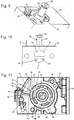
- the roller body 54 is formed in one piece.
- a further advantageous design variant is shown schematically, in which the roller body is constructed from two parts 54a and 54b connected to one another.
- the parts 54a and 54b are advantageously firmly, in particular permanently connected to one another. However, a detachable connection of the two parts 54a and 54b, for example a screw connection, can also be advantageous.
- the part 54a is cylindrical and has the channels 33 and 34.
- the part 54a is advantageously made of media-resistant plastic or metal.
- the part 54b is designed as a flat disk and has the control contour 57.
- the part 54b is advantageously made of plastic.
- the material of the part 54b is advantageously matched to the material of the pivot lever 49 in such a way that there are low frictional forces between the control contour 57 and the pivot lever 49.
- the parts 54a and 54b are adjusted to one another in particular before the fixed, in particular materially bonded connection with one another, so that small tolerances arise between the control contour 57 and the channels 33 and 34.
- the position of the parts 54a and 54b with respect to one another can also be determined structurally, for example by means of a stop or the like.
- Fig. 8 shows the carburetor housing 19 with the carburetor roller 20 in a top view without cover 21 (see Fig. 3 ). As a result, the carburetor roller 20 and the switch 22 are visible.
- a pivot lever 49 is advantageously mounted on the carburetor housing 19 so as to be pivotable about a pivot axis 62 of the pivot lever 49.
- the pivot axis 62 of the pivot lever 49 is arranged at a distance c from the pivot axis 35 of the carburetor roller 20.
- the distance c is advantageously greater than the distance b between the outer circumferential surface 60 and the pivot axis 35 of the carburetor roller 20.
- the pivot axis 62 of the pivot lever 49 is therefore outside the roller body 20.
- the pivot axis 62 of the pivot lever 49 is preferably aligned parallel to the pivot axis 35 of the carburetor roller 20.
- the pivot lever 49 advantageously has a nose which rests on the carburetor roller 20 and which forms a detection means 56 for detecting the rotational position of the carburetor roller 20.
- the detection means 56 together with the control contour 57 forms a detection device 55 for detecting the rotational position of the carburetor drum 20.
- the pivot lever 49 can have a recess 72 adjacent to the detection means 56 which avoids contact of this region of the pivot lever 49 with the outer circumferential surface 60.
- the detection means 56 rests on the bottom 58 of the first depression 47.
- the base 58 has a distance a from the pivot axis 35 of the carburetor roller 20 which is smaller than the distance b from the outer circumferential surface 60 to the pivot axis 35 of the carburetor roller 20.
- the pivot lever 49 is pretensioned in the direction of the position of the detection means 56 which is located radially inward in relation to the pivot axis 35 of the carburetor roller 20.
- the bias of the pivot lever 49 is in Fig. 8 indicated by an arrow 71.
- the preload of the pivot lever 49 can be adjusted by a return spring 70 ( Fig. 14 ), which is part of the switch 22.
- the preload can also be applied by a spring element separate from the switch 22.
- the preload is applied in the direction of arrow 71 by a separate spring element. Due to the bias, the detection means 56 rests on the bottom 58 of the recess 47.
- a contact pin 51 which forms the switch 22 with the spring 50, is advantageously fixed on the pivot lever 49. In the switching position shown, the contact pin 51 is at a distance d from the spring 50, which is designed as a contact spring. The contact pin 51 is therefore not connected to the spring 50 in an electrically conductive manner.
- the switch 22 is open.
- the spring 50 rests against a contact 53 of a diode 52 which is connected to the control device 45.
- the contact pin 51 protrudes from the pivot lever 49 advantageously parallel to the pivot axis 35 upwards.
- Fig. 10 shows an embodiment of a carburetor with a carburetor roller 20 in the idle position.
- the idle position relates to the operation of the internal combustion engine 1 in idle, i.e. when the internal combustion engine 1 is running without a user accelerating, for example by means of an operating element 42 ( Fig. 1 ).
- the first feed channel 8 is completely closed in the idling position of the carburetor roller 20.
- a small flow cross section is released via the groove 63. This allows a small amount of combustion air to flow through the second supply duct 9 and fuel from the fuel opening 28 ( Fig. 2 ) take with you.
- the roller body 20 reaches the into the Figures 11 to 13 Part load position shown.
- the detection means 56 slides from the floor 58 over the incline 79 onto the outer circumferential surface 60.
- the inclination of the incline 79 adjusts the forces exerted by the pivot lever 49 on the carburetor roller 20 and thus on the operating element 42 during the transition from the idle position to the partial load position.
- the forces exerted by the pivot lever 49 on the carburetor drum 20 and thus on the operating element 42 are set during the transition from the full load position to the part load position.
- the inclination of the bevels 79 and 80 is advantageously chosen so that the forces exerted by the pivot lever 49 on the carburetor roller 20 are as small as possible.
- the detection means 56 is on a slope 79, 80, the switching state of the switch 22 is not defined.
- the bevels 79 and 80 are advantageously short in the circumferential direction.
- the recesses 47 and 48 can, as in Fig.
- the depressions 47, 48 can, however, also be designed without an incline on this side, as in FIG Fig. 8 is shown.
- the Figures 11 to 13 show the arrangement with the carburetor roller 20 in the partial load position. Like in particular the Fig. 11 and Fig. 12 show, the depressions 47 and 48 also extend in the embodiment according to FIGS Figures 11 to 13 up to the top 25.
- the part load position refers to the operation of the internal combustion engine 1 in part load, i.e. when the internal combustion engine 1 is running and a user accelerates, for example by means of an operating element 42 ( Fig. 1 ). When the operating element 42 is completely depressed, a full throttle position is present. In a partial load position, the carburetor roller 20 is between the idle position and the full throttle position. How Fig. 13 shows, the first feed channel 8 and the second feed channel 9 are partially open in the partial load position.
- the detection means 56 in the exemplary embodiment the nose of the pivot lever 49, has moved out of the first recess 47 along the slope 79 during the rotary movement of the carburetor roller 20 and is now in contact with the outer circumferential surface 60.
- the detection device 56 lies at the distance b from the pivot axis 35, that is to say it has been moved radially outward with respect to the pivot axis 35.
- the pivot lever 49 was pivoted about the pivot axis 62.
- the contact pin 51 has moved accordingly about the pivot axis 62 and is now in contact with the spring 50.
- the switch 22 formed by the contact pin 51 and the spring 50 is closed.
- the contact pin 51 is connected in an electrically conductive manner to the contact 53 of the diode 52 via the spring 50.
- the control device 45 receives a signal which indicates that the carburetor roller 20 is in a partial load position. How Fig. 13 shows, the first feed channel 8 and the second feed channel 9 are partially open in the partial load position.
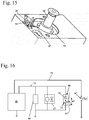
- the Fig. 14 and 15th show the arrangement in full throttle position.
- the full throttle position relates to the operation of the internal combustion engine 1 at full throttle, i.e. an operating state in which the internal combustion engine 1 is running and a user accelerates and, for example, completely depresses the control element 42 ( Fig. 1 In the full throttle position, the detection means 56 rests on the bottom 58 of the second recess 48. As a result, the pivot lever 49 has pivoted back about the pivot axis 62. The pivot lever 49 is reset due to an in Fig. 14 return spring 70 shown.
- the return spring 70 is connected to the contact pin 51 in every position of the pivot lever 49.
- the ground contact is established via the return spring 70.
- the contact pin 51 is not contacted by the spring 50 in the pivoted-back position of the pivot lever 49 (corresponding to FIG Fig. 8 ).
- the switch 22 is open.
- the recesses 47 and 48 only have a bevel 79, 80 on the sides, via which the actuating means 56 comes when adjusting from the idle position to the part-load position and when adjusting from the part-load position to the full-load position.
- the wall is rounded and steep, so that the actuating means 56 on the side facing away from the other recess 47, 48 cannot emerge from the recesses 47 and 48. This is usually prevented in any case by means of corresponding stops on the carburetor roller 20, which set the idle position and the full load position.
- the recesses 47 and 48 can have a different geometry.
- the recesses 47 and 48 can, however, also have an identical geometry and can be arranged in mirror symmetry, such as Fig. 8 shows.
- one of the depressions 47, 48 can be designed deeper, longer, more rounded or angular than the other of the depressions 47, 48.
- the bevels 59, 79, 80 and / or 81 are designed differently.
- a bevel 79, 80 can be designed as a bevel
- the contour arranged at the other end of the recess 47, 48 can be designed as a sharp edge.
- the depressions 47 and 48 can, for example, alternatively or additionally have different depths. These different configurations can be used by the detection device 55 to detect the different positions.
- the different trainings can also be used in order to be able to identify unambiguous positions of the carburetor roller 20 during manufacture.
- an alternative position detection can alternatively be used for at least one switch position, for example a lever in combination with a potentiometer.
- Fig. 16 shows schematically a circuit diagram of the arrangement.
- the control device 45 is connected to a short circuit button 67 via a line 72.
- the control device 45 advantageously has a microprocessor.
- the short circuit button 67 is to be actuated by the operator and can also be designed as a switch.
- the short circuit button 67 is used to switch the ignition of the internal combustion engine 1 ( Fig. 2 ) short-circuit and thereby switch off the internal combustion engine 1.
- the control device 45 is connected via a further line 73 to a connection 66 for a diagnostic device, the fuel valve 27 as well as the diode 52 and the switch 22.
- the connection 66 for diagnosis, the fuel valve 27 and the switch 22 are advantageously connected in parallel.
- the switch 22 is opened or closed depending on the position of the control contour 57. In Fig. 16 the movement of the control contour 57 is indicated schematically by an arrow 65.
- the switch 22 is open in the idling state and in the full load state and is closed in the intermediate partial load state. It is provided that the control device 45 controls the amount of fuel supplied via the fuel valve 27 as a function of the rotational position of the carburetor drum 20 determined by the detection device 55.
- the detection device 55 is formed by the switch 22, the detection means 56, the control contour 57 and the diode 52.
- the detection means 56 when the carburetor cylinder 20 is in a rotational position between the idling position and the full load position, is not located on the outer circumferential surface 60 of the carburetor cylinder 20 on the carburetor cylinder 20, but on a curved surface whose radius around the pivot axis 35 of the carburetor roller 20 differs from that of the outer circumferential surface 60, which is therefore closer to the pivot axis 35 of the carburetor roller 20 or further away from the pivot axis 35.
Landscapes
- Engineering & Computer Science (AREA)
- Chemical & Material Sciences (AREA)
- Combustion & Propulsion (AREA)
- Mechanical Engineering (AREA)
- General Engineering & Computer Science (AREA)
- Control Of Throttle Valves Provided In The Intake System Or In The Exhaust System (AREA)
- Output Control And Ontrol Of Special Type Engine (AREA)
Description
Die Erfindung betrifft einen Vergaser für den Verbrennungsmotor in einem handgeführten Arbeitsgerät der im Oberbegriff des Anspruchs 1 angegebenen Gattung, einen Verbrennungsmotor mit einem Vergaser und ein Verfahren zum Betrieb eines Verbrennungsmotors.The invention relates to a carburetor for the internal combustion engine in a hand-held tool of the type specified in the preamble of claim 1, an internal combustion engine with a carburetor and a method for operating an internal combustion engine.
Aus der
Die
Aus der
Der Erfindung liegt die Aufgabe zugrunde, einen Vergaser der gattungsgemäßen Art zu schaffen, der einfach aufgebaut ist und eine genaue Erfassung zumindest einer Drehstellung der Vergaserwalze ermöglicht. Eine weitere Aufgabe der Erfindung liegt darin, einen Verbrennungsmotor mit einem Vergaser sowie ein Verfahren zum Betrieb eines Verbrennungsmotors anzugeben.The invention is based on the object of creating a carburetor of the generic type which has a simple structure and enables precise detection of at least one rotational position of the carburetor cylinder. Another object of the invention is to provide an internal combustion engine with a carburetor and a method for operating an internal combustion engine.
Diese Aufgabe wird bezüglich des Vergasers für den Verbrennungsmotor in einem handgeführten Arbeitsgerät durch einen Vergaser mit den Merkmalen des Anspruchs 1 gelöst. Bezüglich des Verbrennungsmotors wird die Aufgabe durch einen Verbrennungsmotor mit den Merkmalen des Anspruchs 13 gelöst. Bezüglich des Verfahrens wird die Aufgabe durch ein Verfahren mit den Merkmalen des Anspruchs 14 gelöst.This object is achieved with regard to the carburetor for the internal combustion engine in a hand-held tool by a carburetor with the features of claim 1 solved. With regard to the internal combustion engine, the object is achieved by an internal combustion engine having the features of
Es ist vorgesehen, dass die Erfassungseinrichtung eine Steuerkontur und ein mit der Steuerkontur zusammenwirkendes Erfassungsmittel umfasst und dass die Steuerkontur unmittelbar an der Vergaserwalze ausgebildet ist. Durch die Anordnung der Steuerkontur an der Vergaserwalze können Toleranzen zwischen der Lage der Steuerkontur und der Lage der Vergaserwalze minimiert werden. Eine Steuerkontur kann auf einfache Weise bei der Herstellung der Vergaserwalze in die Vergaserwalze eingebracht werden. Eine Steuerkontur ist dabei eine mechanisch abzutastende Kontur, beispielsweise eine Erhebung oder Vertiefung am Außenumfang der Vergaserwalze. Eine Steuerkontur kann durch mechanische Bearbeitung der Vergaserwalze einfach hergestellt werden. Zur Erfassung der Drehstellung der Vergaserwalze ist vorteilhaft vorgesehen, dass die Steuerkontur in unterschiedlichen Umfangsabschnitten der Vergaserwalze unterschiedliche Abstände zur Schwenkachse der Vergaserwalze aufweist, die von dem Erfassungsmittel erfasst werden. Bevorzugt ist vorgesehen, dass das Erfassungsmittel die Steuerkontur abtastet.It is provided that the detection device comprises a control contour and a detection means that interacts with the control contour and that the control contour is formed directly on the carburetor roller. The arrangement of the control contour on the carburetor cylinder allows tolerances between the position of the control contour and the position of the carburetor cylinder to be minimized. A control contour can be introduced into the carburetor cylinder in a simple manner during the manufacture of the carburetor cylinder. A control contour is a contour to be mechanically scanned, for example an elevation or depression on the outer circumference of the carburetor roller. A control contour can be easily produced by machining the carburetor roller. To detect the rotational position of the carburetor roller, it is advantageously provided that the control contour has different distances from the pivot axis of the carburetor roller in different circumferential sections of the carburetor roller, which are detected by the detection means. It is preferably provided that the detection means scans the control contour.
Die Erfassungseinrichtung ist dazu ausgebildet, ein elektrisches Signal zu erzeugen. Das von der Erfassungseinrichtung erzeugte Signal kann insbesondere in einer Auswerteeinheit ausgelesen werden und kann vorteilhaft zur Steuerung einer Kraftstoffzuführeinrichtung genutzt werden. Die Auswerteeinheit kann beispielsweise ein Steuergerät eines Verbrennungsmotors sein.The detection device is designed to generate an electrical signal. The signal generated by the detection device can in particular be read out in an evaluation unit and can advantageously be used to control a fuel supply device. The evaluation unit can be, for example, a control unit of an internal combustion engine.
Bevorzugt ist die Steuerkontur unmittelbar an der Vergaserwalze angeordnet. Die Steuerkontur ist insbesondere an einer Oberseite der Vergaserwalze angeordnet. Die Steuerkontur ist insbesondere einteilig mit dem Teil der Vergaserwalze ausgebildet, der den mindestens einen quer zur Schwenkachse verlaufenden Kanal aufweist. Dadurch können Toleranzen zwischen dem mindestens einen Kanal und der Steuerkontur minimiert werden.The control contour is preferably arranged directly on the carburetor roller. The control contour is arranged in particular on an upper side of the carburetor roller. The control contour is in particular formed in one piece with that part of the carburetor roller which has the at least one channel running transversely to the pivot axis. Thereby tolerances between the at least one channel and the control contour can be minimized.
Vorteilhaft ist die Vergaserwalze mehrteilig ausgebildet. Vorteilhaft weist ein erstes Teil der Vergaserwalze die Steuerkontur auf und ein zweites Teil den mindestens einen Kanal. Das erste Teil und das zweite Teil sind vorteilhaft fest miteinander verbunden, insbesondere durch Schweißen, Kleben oder dgl. Die beiden Teile sind insbesondere stoffschlüssig miteinander verbunden. Dadurch können die Steuerkontur und der mindestens eine Kanal einfach hergestellt werden. Die mindestens zwei Teile der Vergaserwalze können vorteilhaft aus unterschiedlichen Materialien bestehen. Dadurch kann die Steuerkontur in einem Teil aus verschließfestem Material, beispielsweise einem Kunststoff, und der mindestens eine Kanal in einem kraftstoffbeständigen Material, beispielsweise Metall oder ein anderer Kunststoff, ausgebildet sein. Die beiden Teile können während der Fertigung vor der festen Verbindung der Teile miteinander zueinander genau positioniert werden, so dass geringe Toleranzen eingehalten werden können.The carburetor roller is advantageously designed in several parts. A first part of the carburetor roller advantageously has the control contour and a second part has the at least one channel. The first part and the second part are advantageously firmly connected to one another, in particular by welding, gluing or the like. The two parts are in particular connected to one another in a materially bonded manner. As a result, the control contour and the at least one channel can be easily produced. The at least two parts of the carburetor roller can advantageously consist of different materials. As a result, the control contour can be formed in a part from wear-resistant material, for example a plastic, and the at least one channel can be formed in a fuel-resistant material, for example metal or another plastic. The two parts can be precisely positioned to one another during production before the parts are firmly connected to one another, so that small tolerances can be maintained.
Vorteilhaft ist die Steuerkontur an dem Walzenkörper angeordnet. Dadurch kann die Steuerkontur mit vergleichsweise großem Abstand zur Schwenkachse des Walzenkörpers ausgeführt werden. Dadurch werden Toleranzen bei der Erfassung der Drehstellung der Vergaserwalze minimiert. Die Steuerkontur ist bevorzugt in dem Bereich des Walzenkörpers angeordnet, der den größten Durchmesser besitzt. Die Steuerkontur ist vorteilhaft im Walzenkörper der Vergaserwalze ausgebildet. Dabei ist der Walzenkörper der Vergaserwalze in vorteilhafter Gestaltung einteilig ausgebildet. In vorteilhafter alternativer Gestaltung ist der Walzenkörper aus zwei fest miteinander verbundenen Teilen aufgebaut.The control contour is advantageously arranged on the roller body. As a result, the control contour can be designed with a comparatively large distance from the pivot axis of the roller body. This minimizes tolerances when detecting the rotary position of the carburetor drum. The control contour is preferably arranged in the region of the roller body which has the largest diameter. The control contour is advantageously formed in the roller body of the carburetor roller. The roller body of the carburetor roller is designed in one piece in an advantageous design. In an advantageous alternative design, the roller body is made up of two parts that are firmly connected to one another.
Bevorzugt umfasst die Steuerkontur mindestens eine Vertiefung am Umfang der Vergaserwalze. Die Steuerkontur umfasst vorteilhaft mindestens eine Vertiefung im Umfang des Walzenkörpers der Vergaserwalze. In vorteilhafter Gestaltung umfasst die Steuerkontur eine erste Vertiefung, die dem Leerlauf zugeordnet ist. In besonders bevorzugter Gestaltung umfasst die Steuerkontur eine erste Vertiefung, die dem Leerlauf zugeordnet ist, und eine zweite Vertiefung, die der Volllast zugeordnet ist. Über die Steuerkontur kann demnach die Leerlaufstellung ermittelt werden. Besonders vorteilhaft kann über die Steuerkontur die Leerlaufstellung und die Volllaststellung ermittelt werden. Der Teillastbereich, der zwischen der Leerlaufstellung und der Volllaststellung gegeben ist, kann durch ein von der Leerlaufstellung und der Volllaststellung abweichendes Signal ermittelt werden. Dadurch ist über zwei Schaltzustände der Erfassungseinrichtung die Erfassung der Lage aller für die Steuerung des Verbrennungsmotors wichtigen Lagen des Walzenkörpers möglich. Die Unterscheidung zwischen Leerlaufstellung und Volllaststellung kann durch unterschiedliche Signale in Leerlaufstellung und Volllaststellung, beispielsweise über unterschiedlich tiefe Vertiefungen für Leerlaufstellung und Volllaststellung, erreicht werden. In besonders bevorzugter Gestaltung wird durch die Erfassungseinrichtung in Leerlaufstellung und Volllaststellung das gleiche Signal erfasst, und die Unterscheidung zwischen Leerlaufstellung und Volllaststellung erfolgt über weitere Informationen, insbesondere anhand einer Drehzahl des Verbrennungsmotors.The control contour preferably comprises at least one depression on the circumference of the carburetor roller. The control contour advantageously comprises at least one depression in the circumference of the roller body of the carburetor roller. In an advantageous embodiment, the control contour comprises a first depression which is assigned to the idle. Especially In a preferred embodiment, the control contour comprises a first recess, which is assigned to idling, and a second recess, which is assigned to full load. The idle position can therefore be determined via the control contour. The idling position and the full load position can be determined particularly advantageously via the control contour. The partial load range that exists between the idle position and the full load position can be determined by a signal that deviates from the idle position and the full load position. As a result, the position of all positions of the roller body that are important for controlling the internal combustion engine can be detected via two switching states of the detection device. The distinction between the idle position and the full load position can be achieved by different signals in the idle position and the full load position, for example by means of different depths for the idle position and the full load position. In a particularly preferred embodiment, the detection device detects the same signal in the idle position and the full load position, and the distinction between the idle position and the full load position is made using further information, in particular on the basis of a speed of the internal combustion engine.
Die Abtastung der Steuerkontur wirkt vorteilhaft auf ein Bedienelement, beispielsweise einen Gashebel, über den der Bediener die Vergaserwalze verstellt, zurück. Um die von der Erfassungseinrichtung auf den Gashebel ausgeübten Kräfte möglichst gering zu halten, ist vorteilhaft vorgesehen, dass mindestens eine Vertiefung einen die Vertiefung in radialer Richtung begrenzenden Boden besitzt. Der Boden geht vorteilhaft an mindestens einer in Umfangsrichtung liegenden Seite mit einer Schräge in die Außenumfangsfläche der Vergaserwalze über. Über die Schräge können die von der Steuerkontur auf das Erfassungsmittel ausgeübten Kräfte beim Übergang von der Vertiefung in die Außenumfangsfläche der Vergaserwalze gering gehalten werden. Die Neigung der Schräge ist vorteilhaft so gewählt, dass die Erfassung der Drehstellung der Vergaserwalze ausreichend genau möglich ist, gleichzeitig aber geringe Kräfte von der Schräge auf den Gashebel ausgeübt werden, die vom Bediener vorteilhaft nicht oder kaum bemerkt werden. In bevorzugter Gestaltung begrenzt der Boden die Vertiefung in radial innen liegender Richtung.The scanning of the control contour has an advantageous effect on an operating element, for example a throttle lever, via which the operator adjusts the carburetor roller. In order to keep the forces exerted by the detection device on the throttle lever as low as possible, it is advantageously provided that at least one recess has a base that delimits the recess in the radial direction. The bottom advantageously merges into the outer circumferential surface of the carburetor roller with a slope on at least one side lying in the circumferential direction. The forces exerted by the control contour on the detection means during the transition from the depression to the outer circumferential surface of the carburetor roller can be kept low via the incline. The inclination of the incline is advantageously chosen so that the rotational position of the carburetor roller can be detected with sufficient accuracy, but at the same time low forces from the incline be exercised on the throttle, which are advantageously not or hardly noticed by the operator. In a preferred embodiment, the bottom delimits the depression in a radially inner direction.
In alternativer Gestaltung kann vorgesehen sein, dass der Boden der Vertiefung mit der Schräge in ein gekrümmtes Flächensegment übergeht. Das Flächensegment ist vorteilhaft mit einem oder mehreren Radien um die Schwenkachse des Walzenkörpers gekrümmt. Die Radien unterscheiden sich dabei vorteilhaft vom Abstand des Bodens der Vertiefung zur Schwenkachse, so dass das Flächensegment und der Boden der Vertiefung mit unterschiedlichen Radien ausgebildet sind. Über das gekrümmte Flächensegment kann ein weiterer Schaltzustand der Erfassungseinrichtung erreicht werden. Insbesondere können hierdurch weitere Drehstellungen des Walzenkörpers erfasst werden. Das gekrümmte Flächensegment kann ein Flächensegment sein, dessen Radius kleiner als der der Außenumfangsfläche der Vergaserwalze ist, um die Anordnung in einem geringeren Bauraum zu ermöglichen. In alternativer Gestaltung ist der Radius des gekrümmten Flächensegments größer als der der Außenumfangsfläche. Dadurch kann die Genauigkeit der Erfassung der Drehstellung des Walzenkörpers erhöht werden.In an alternative design, it can be provided that the bottom of the recess merges with the incline into a curved surface segment. The surface segment is advantageously curved with one or more radii around the pivot axis of the roller body. The radii advantageously differ from the distance between the bottom of the recess and the pivot axis, so that the surface segment and the bottom of the recess are designed with different radii. A further switching state of the detection device can be achieved via the curved surface segment. In particular, this allows further rotational positions of the roller body to be recorded. The curved surface segment can be a surface segment whose radius is smaller than that of the outer circumferential surface of the carburetor roller in order to enable the arrangement in a smaller installation space. In an alternative configuration, the radius of the curved surface segment is greater than that of the outer circumferential surface. As a result, the accuracy of the detection of the rotational position of the roller body can be increased.
Der Boden der Vertiefung begrenzt die Vertiefung vorteilhaft an der bezogen auf die Schwenkachse radial innen liegende Seite. In vorteilhafter Gestaltung liegt das Erfassungsmittel bezogen auf die Schwenkachse radial außerhalb der Steuerkontur an der Steuerkontur an. Das Erfassungsmittel ist vorteilhaft bezogen auf die Schwenkachse radial nach innen von einer Rückstellfeder federbelastet. Vorteilhaft umfasst die Erfassungseinrichtung einen Schalter, der in Abhängigkeit der Position des Erfassungsmittels betätigt ist. Über einen Schalter kann auf einfache Weise eine Erfassung von mindestens zwei Schaltzuständen erfolgen. Ein von einem Schalter generiertes elektrisches Signal kann auf einfache Weise elektronisch weiterverarbeitet werden, insbesondere von einer elektronischen Steuereinrichtung.The bottom of the recess advantageously delimits the recess on the side lying radially inward relative to the pivot axis. In an advantageous embodiment, the detection means rests on the control contour radially outside the control contour in relation to the pivot axis. The detection means is advantageously spring-loaded radially inward by a return spring with respect to the pivot axis. The detection device advantageously comprises a switch which is actuated as a function of the position of the detection means. At least two switching states can be detected in a simple manner via a switch. An electrical signal generated by a switch can be further processed electronically in a simple manner, in particular by an electronic control device.
Das Erfassungsmittel ist bevorzugt an einem Schwenkhebel ausgebildet, der am Vergasergehäuse um eine parallel zur Schwenkachse der Vergaserwalze liegende zweite Schwenkachse schwenkbar gelagert ist. In besonders bevorzugter Gestaltung ist der Schwenkhebel über die Rückstellfeder mit Masse verbunden. Die Rückstellfeder ist demnach eine Kontaktfeder, über die ein elektrischer Kontakt zur Masse hergestellt wird. Dadurch ergibt sich ein einfacher Aufbau mit wenigen Komponenten. Es kann jedoch auch vorgesehen sein, dass zur Herstellung des Massekontakts und zur Vorspannung des Schwenkhebels in seine radial innenliegende Position unterschiedliche Federelemente zum Einsatz kommen.The detection means is preferably formed on a pivot lever which is mounted on the carburetor housing so as to be pivotable about a second pivot axis lying parallel to the pivot axis of the carburetor drum. In a particularly preferred embodiment, the pivot lever is connected to ground via the return spring. The return spring is therefore a contact spring, via which an electrical contact to ground is established. This results in a simple structure with few components. However, it can also be provided that different spring elements are used to establish the ground contact and to preload the pivot lever into its radially inner position.
Vorteilhaft ist ein Kraftstoffventil vorgesehen, über das Kraftstoff in den Ansaugkanal zugeführt wird. Aufgrund der Erfassung mindestens einer Drehstellung des Walzenkörpers kann das Kraftstoffventil angesteuert werden, und die benötigte Kraftstoffmenge kann genau dosiert werden. Für einen Verbrennungsmotor mit einem Vergaser mit einem Kraftstoffventil ist vorgesehen, dass der Verbrennungsmotor eine Steuereinrichtung besitzt, die mit der Erfassungseinrichtung und dem Kraftstoffventil zur Zufuhr von Kraftstoff in den Ansaugkanal verbunden ist.A fuel valve is advantageously provided, via which fuel is fed into the intake duct. On the basis of the detection of at least one rotational position of the roller body, the fuel valve can be activated and the required amount of fuel can be precisely metered. For an internal combustion engine with a carburetor with a fuel valve, it is provided that the internal combustion engine has a control device which is connected to the detection device and the fuel valve for feeding fuel into the intake duct.
Ein Verfahren zum Betrieb eines Verbrennungsmotors sieht vorteilhaft vor, dass die Steuereinrichtung die zugeführte Kraftstoffmenge in Abhängigkeit der von der Erfassungseinrichtung erfassten Drehstellung der Vergaserwalze steuert. Dadurch wird eine genaue Dosierung von Kraftstoff ermöglicht, insbesondere, wenn die gesamte dem Ansaugkanal zugeführte Kraftstoffmenge über ein einziges Kraftstoffventil dosiert wird. Vorteilhaft kann vorgesehen sein, mittels der Erfassung mindestens einer Drehstellung der Vergaserwalze die Steuerung der Zündung des Verbrennungsmotors zu beeinflussen.A method for operating an internal combustion engine advantageously provides that the control device controls the amount of fuel supplied as a function of the rotational position of the carburetor drum detected by the detection device. This enables precise metering of fuel, in particular if the entire amount of fuel supplied to the intake duct is metered via a single fuel valve. Provision can advantageously be made to influence the control of the ignition of the internal combustion engine by means of the detection of at least one rotational position of the carburetor drum.
Ein Ausführungsbeispiel der Erfindung wird im Folgenden anhand der Zeichnung erläutert. Es zeigen:
- Fig. 1
- eine schematische perspektivische Darstellung eines Arbeitsgeräts,
- Fig. 2
- eine schematische Schnittdarstellung eines Verbrennungsmotors des Arbeitsgeräts aus
Fig. 1 , - Fig. 3
- eine schematische Schnittdarstellung des Vergasers des Verbrennungsmotors aus
Fig. 2 , - Fig. 4
- eine perspektivische Darstellung der Vergaserwalze des Vergasers aus
Fig. 3 , - Fig. 5
- eine Seitenansicht der Vergaserwalze aus
Fig. 4 , - Fig. 6
- eine Draufsicht auf die Vergaserwalze aus
Fig. 5 in Richtung des Pfeils VI inFig. 5 , - Fig. 7
- eine Seitenansicht der Vergaserwalze in Richtung des Pfeils VII in
Fig. 5 , - Fig. 8
- eine schematische Draufsicht auf den Vergaser mit abgenommenem Deckel in Leerlaufstellung eines Ausführungsbeispiels der Vergaserwalze,
- Fig. 9
- eine schematische perspektivische Darstellung von Schwenkhebel und Vergaserwalze in der Schaltstellung aus
Fig. 8 , - Fig. 10
- eine Seitenansicht des Vergasers in der Stellung aus den
Fig. 8 und 9 , - Fig. 11
- eine Draufsicht auf den Vergaser mit abgenommenem Deckel mit der Vergaserwalze aus
Fig. 8 in Teillaststellung, - Fig. 12
- eine perspektivische Darstellung von Schwenkhebel und Vergaserwalze in der Stellung aus
Fig. 11 , - Fig. 13
- eine Seitenansicht des Vergasers in der Schaltstellung aus den
Fig. 11 und 12 , - Fig. 14
- eine Draufsicht auf den Vergaser mit der Vergaserwalze aus den
Fig. 4 in Volllaststellung,bis 7 - Fig. 15
- eine schematische perspektivische Darstellung des Vergasers in der Stellung aus
Fig. 14 , - Fig. 16
- ein Schaltbild der Erfassungseinrichtung und einer Steuereinrichtung des Verbrennungsmotors.
- Fig. 1
- a schematic perspective illustration of an implement,
- Fig. 2
- a schematic sectional view of an internal combustion engine of the implement from FIG
Fig. 1 , - Fig. 3
- a schematic sectional view of the carburetor of the internal combustion engine
Fig. 2 , - Fig. 4
- a perspective view of the carburetor roller of the carburetor
Fig. 3 , - Fig. 5
- a side view of the carburetor roller
Fig. 4 , - Fig. 6
- a top view of the carburetor roller
Fig. 5 in the direction of arrow VI inFig. 5 , - Fig. 7
- a side view of the carburetor roller in the direction of arrow VII in
Fig. 5 , - Fig. 8
- a schematic plan view of the carburetor with the cover removed in the idle position of an embodiment of the carburetor roller,
- Fig. 9
- a schematic perspective view of the pivot lever and carburetor roller in the switching position
Fig. 8 , - Fig. 10
- a side view of the carburetor in the position from FIG
Fig. 8 and9 , - Fig. 11
- a top view of the carburetor with the cover removed with the carburetor roller
Fig. 8 in partial load position, - Fig. 12
- a perspective view of the pivot lever and carburetor roller in the position from
Fig. 11 , - Fig. 13
- a side view of the carburetor in the switching position from the
Fig. 11 and12th , - Fig. 14
- a top view of the carburetor with the carburetor roller from the
Figures 4 to 7 in full load position, - Fig. 15
- a schematic perspective view of the carburetor in the position from
Fig. 14 , - Fig. 16
- a circuit diagram of the detection device and a control device of the internal combustion engine.
Der Gemischeinlass 11 und der Lufteinlass 10 sind vom Kolbenhemd des Kolbens 5 gesteuert. Der Verbrennungsmotor 1 des Ausführungsbeispiels ist ein schlitzgesteuerter Motor. Der Gemischeinlass 11 ist im Bereich des oberen Totpunkts des Kolbens 5 mit dem Innenraum des Kurbelgehäuses 4 verbunden. Der Lufteinlass 10 mündet in einem Bereich des Kolbens 5, in dem sich eine Kolbentasche 12 des Kolbens 5 bewegt. Die Kolbentasche 12 verbindet den Lufteinlass 10 im Bereich des oberen Totpunkts des Kolbens 5 mit den Überströmfenstern 15 der auslassnahen Überströmkanäle 13 und der auslassfernen Überströmkanäle 14. Die Darstellung in
Im Betrieb des Verbrennungsmotors 1 wird beim Aufwärtshub des Kolbens 5 Kraftstoff/Luft-Gemisch aus dem zweiten Zuführkanal 9 über den Gemischeinlass 11 in den Innenraum des Kurbelgehäuses 4 gesaugt. Sobald die Kolbentaschen 12 den mindestens einen Lufteinlass 10 mit den Überströmfenstern 15 verbinden, wird kraftstofffreie oder kraftstoffarme Verbrennungsluft aus dem ersten Zuführkanal 8 über die Überströmfenster 15 in die Überströmkanäle 13 und 14 gesaugt. Das Kraftstoff/Luft-Gemisch im Innenraum des Kurbelgehäuses 4 wird beim darauffolgenden Abwärtshub, also der Bewegung des Kolbens 5 vom Brennraum 3 in Richtung auf das Kurbelgehäuse 4, im Innenraum des Kurbelgehäuses 4 verdichtet. Sobald die Überströmfenster 15 vom abwärts fahrenden Kolben 5 geöffnet werden, strömt aus den Überströmfenstern 15 zunächst kraftstofffreie oder kraftstoffarme Luft in den Brennraum 3. Die kraftstoffarme oder kraftstofffreie Verbrennungsluft spült Abgase aus dem vorangegangenen Motorzyklus aus dem Brennraum 3 durch einen Auslass 16 aus dem Brennraum 3 aus. Anschließend strömt frisches Gemisch aus dem Innenraum des Kurbelgehäuses 4 in den Brennraum 3 nach. Beim darauffolgenden Aufwärtshub des Kolbens wird das Gemisch im Brennraum 3 verdichtet und im Bereich des oberen Totpunkts des Kolbens 5 gezündet und verbrannt. Durch die Verbrennung wird der Kolben 5 wieder in Richtung auf das Kurbelgehäuse 4 beschleunigt. Sobald die Überströmfenster 15 öffnen, strömt zunächst vorgelagerte Luft aus den Überströmkanälen 13 und 14 und anschließend frisches Gemisch aus dem Innenraum des Kurbelgehäuses 4 über die Überströmkanäle 13 und 14 in den Brennraum 3 nach.During operation of the internal combustion engine 1, during the upward stroke of the
Wie
In alternativer Ausführung kann vorgesehen sein, dass zur Steuerung der zugeführten Kraftstoffmenge eine Steuernadel in die Kraftstofföffuung 28 ragt und sich die Größe eines zwischen Steuernadel und Kraftstofföffnung gebildeten Ringspalts in Abhängigkeit der Drehstellung der Vergaserwalze 20 ändert. Zur Änderung der Größe des Ringspalts ist es bekannt, eine Rampe zwischen Vergasergehäuse 19 und Vergaserwalze 20 vorzusehen, über die die Vergaserwalze 20 bei einer Schwenkbewegung um die Schwenkachse 35 in Richtung der Schwenkachse 35 bewegt wird.In an alternative embodiment it can be provided that a control needle protrudes into the
Die
An der dem Walzenschaft 61 benachbart liegenden Seite des Walzenkörpers 54 weist der Walzenkörper 54 an seinem Außenumfang eine Steuerkontur 57 auf. Die Steuerkontur 57 dient zur Erfassung der Drehlage der Vergaserwalze 20 und betätigt den Schalter 22 (
Wie
Wie
Im Ausführungsbeispiel ist der Walzenkörper 54 einteilig ausgebildet. In den
Die Teile 54a und 54b sind vorteilhaft fest, insbesondere unlösbar miteinander verbunden. Auch eine lösbare Verbindung der beiden Teile 54a und 54b, beispielsweise eine Schraubverbindung, kann jedoch vorteilhaft sein. Das Teil 54a ist walzenförmig ausgebildet und weist die Kanäle 33 und 34 auf. Das Teil 54a besteht vorteilhaft aus medienbeständigem Kunststoff oder Metall. Das Teil 54b ist im Ausführungsbeispiel als flache Scheibe ausgebildet und weist die Steuerkontur 57 auf. Das Teil 54b besteht vorteilhaft aus Kunststoff. Das Material des Teils 54b ist vorteilhaft so auf das Material des Schwenkhebels 49 abgestimmt, dass sich geringe Reibkräfte zwischen Steuerkontur 57 und Schwenkhebel 49 ergeben. Die Teile 54a und 54b sind insbesondere vor der festen, insbesondere stoffschlüssigen Verbindung miteinander zueinander justiert, so dass sich geringe Toleranzen zwischen der Steuerkontur 57 und den Kanälen 33 und 34 ergeben. Alternativ kann die Position der Teile 54a und 54b zueinander auch konstruktiv, beispielsweise über einen Anschlag oder dgl., festgelegt sein.The
In der gezeigten Leerlaufstellung der Vergaserwalze 20 liegt das Erfassungsmittel 56 am Boden 58 der ersten Vertiefung 47 an. Der Boden 58 besitzt zur Schwenkachse 35 der Vergaserwalze 20 einen Abstand a, der kleiner als der Abstand b der Außenumfangsfläche 60 zur Schwenkachse 35 der Vergaserwalze 20 ist. Der Schwenkhebel 49 ist in Richtung auf die bezogen auf die Schwenkachse 35 der Vergaserwalze 20 radial innen liegende Position des Erfassungsmittels 56 vorgespannt. Die Vorspannung des Schwenkhebels 49 ist in
Am Schwenkhebel 49 ist vorteilhaft ein Kontaktpin 51 fixiert, der mit der Feder 50 den Schalter 22 bildet. In der gezeigten Schaltstellung besitzt der Kontaktpin 51 zu der Feder 50, die als Kontaktfeder ausgebildet ist, einen Abstand d. Der Kontaktpin 51 ist demnach nicht elektrisch leitend mit der Feder 50 verbunden. Der Schalter 22 ist geöffnet. Die Feder 50 liegt an einem Kontakt 53 einer Diode 52 an, die mit der Steuereinrichtung 45 verbunden ist.A
Wie die
Wird die Vergaserwalze 20 in Richtung des Pfeils 68 gedreht, beispielsweise durch Drücken des Bedienelements 42 (
Die
Die
In der in den
In den Figuren sind zwei geringfügige unterschiedliche Gestaltungen der Vertiefungen 47 und 48 sowie der Feder 50 gezeigt. Beim Ausführungsbeispiel nach den
Wie
Im Ausführungsbeispiel ist vorgesehen, dass der Schalter 22 im Leerlaufzustand und im Volllastzustand geöffnet und im dazwischenliegenden Teillastzustand geschlossen ist. Es ist vorgesehen, dass die Steuereinrichtung 45 die über das Kraftstoffventil 27 zugeführte Kraftstoffmenge in Abhängigkeit der von der Erfassungseinrichtung 55 ermittelten Drehstellung der Vergaserwalze 20 steuert. Die Erfassungseinrichtung 55 ist im Ausführungsbeispiel durch den Schalter 22, das Erfassungsmittel 56, die Steuerkontur 57 und die Diode 52 gebildet.In the exemplary embodiment, it is provided that the
In alternativer Gestaltung kann vorgesehen sein, dass das Erfassungsmittel 56 bei einer Drehstellung der Vergaserwalze 20 zwischen der Leerlaufstellung und der Volllaststellung nicht an der Außenumfangsfläche 60 der Vergaserwalze 20 an der Vergaserwalze 20 anliegt, sondern an einer gekrümmten Fläche, deren Radius um die Schwenkachse 35 der Vergaserwalze 20 von dem der Außenumfangsfläche 60 abweicht, der also näher an der Schwenkachse 35 der Vergaserwalze 20 oder weiter von der Schwenkachse 35 entfernt angeordnet ist.In an alternative embodiment, it can be provided that the detection means 56, when the
Weitere vorteilhafte Ausführungen ergeben sich durch beliebige Kombination der beschriebenen Ausführungsbeispiele.Further advantageous designs result from any combination of the exemplary embodiments described.
Claims (14)
- Carburettor for the internal combustion engine in a hand-guided working implement, with a carburettor housing (19) wherein, in the carburettor housing (19), a carburettor roller (20) is rotatably mounted around a swivel axis (35), wherein the carburettor roller (20) has a roller body (54), wherein the roller body (54) has at least one channel (33, 34) running transversely to the swivel axis (35) and forming a suction channel section, wherein a detection device (55) is provided to detect at least one rotary position of the carburettor roller (20), wherein the detection device (55) is designed to generate an electrical signal, characterised in that the detection device (55) includes a control contour (57) and detection means (56) acting in conjunction with the control contour (57), and that the control contour (57) is formed on the carburettor roller (20).
- Carburettor according to claim 1,
characterised in that the control contour (57) is located on the roller body (54). - Carburettor according to claim 2,
characterised in that the control contour (57) is located in the area of the roller body (54) which has the greatest diameter. - Carburettor according to any of claims 1 to 3,
characterised in that the control contour (57) includes at least one recess (47, 48) on the circumference of the carburettor roller (20). - Carburettor according to claim 4,
characterised in that the control contour (57) includes a first recess (47), which is assigned to idling and that the control contour (57) includes a second recess (48), which is assigned to full load. - Carburettor according to claim 4 or 5,
characterised in that the recess or recesses (47, 48) has or have a base (58) bounding the recess (47, 48) in the radial direction which, on at least one side of the recess (47, 48) lying in the circumferential direction, merges with a bevel (59, 79, 80, 81) into the outer circumferential surface (60) of the carburettor roller (20). - Carburettor according to any of claims 1 to 6,
characterised in that the detection means (56), relative to the swivel axis (35), make contact with the control contour (57) radially outside the control contour (57). - Carburettor according to any of claims 1 to 7,
characterised in that the detection means (56), relative to the swivel axis (35), are spring-loaded inwards by a return spring (70). - Carburettor according to any of claims 1 to 8,
characterised in that the detection device (55) includes a switch (22) which is actuated depending on the position of the detection means (56). - Carburettor according to any of claims 1 to 9,
characterised in that the detection means (56) are formed on a swivel lever (49) which is pivotably mounted on the carburettor housing (19) around a second swivel axis (58) lying parallel to the swivel axis (35) of the carburettor roller (20). - Carburettor according to claim 10,
characterised in that the swivel lever (49) is connected to earth via the return spring (70). - Carburettor according to any of claims 1 to 11,
characterised in that there is provided a fuel valve (27), through which the fuel is fed into the channel (33) of the carburettor roller (20). - Internal combustion engine with a carburettor according to claim 12,
wherein the internal combustion engine has a control unit (45) which is connected to the detection device (55) and the fuel valve (27) to feed fuel into the suction channel section. - Method of operating an internal combustion engine according to claim 13, wherein the control unit (45) controls the amount of fuel supplied on the basis of the rotary position of the carburettor roller (20) detected by the detection device (55).
Applications Claiming Priority (1)
| Application Number | Priority Date | Filing Date | Title |
|---|---|---|---|
| DE102018000145.9A DE102018000145A1 (en) | 2018-01-10 | 2018-01-10 | Carburetor for the internal combustion engine in a hand-held implement, internal combustion engine with a carburetor and method for operating an internal combustion engine |
Publications (2)
| Publication Number | Publication Date |
|---|---|
| EP3511552A1 EP3511552A1 (en) | 2019-07-17 |
| EP3511552B1 true EP3511552B1 (en) | 2021-03-31 |
Family
ID=65033351
Family Applications (1)
| Application Number | Title | Priority Date | Filing Date |
|---|---|---|---|
| EP19150488.5A Active EP3511552B1 (en) | 2018-01-10 | 2019-01-07 | Carburator for the combustion engine in a hand-held work device, combustion engine with a carburator and method for operating a combustion engine |
Country Status (4)
| Country | Link |
|---|---|
| US (1) | US10718295B2 (en) |
| EP (1) | EP3511552B1 (en) |
| CN (1) | CN110017221B (en) |
| DE (1) | DE102018000145A1 (en) |
Citations (2)
| Publication number | Priority date | Publication date | Assignee | Title |
|---|---|---|---|---|
| DE3247603A1 (en) * | 1981-12-25 | 1983-07-07 | Walbro Far East, Inc., Kawasaki | Carburettor with rotatable throttle valve |
| US4909211A (en) * | 1989-05-17 | 1990-03-20 | Walbro Corporation | Barrel-type throttle valve for engine air intake |
Family Cites Families (20)
| Publication number | Priority date | Publication date | Assignee | Title |
|---|---|---|---|---|
| JP4414027B2 (en) * | 1999-09-03 | 2010-02-10 | 本田技研工業株式会社 | Engine intake system |
| US6439547B1 (en) * | 2001-03-05 | 2002-08-27 | Walbro Corporation | Carburetor throttle and choke control mechanism |
| JP3948948B2 (en) * | 2001-12-06 | 2007-07-25 | 本田技研工業株式会社 | Ignition timing control device for internal combustion engine |
| JP2003278602A (en) * | 2002-03-19 | 2003-10-02 | Alps Electric Co Ltd | Variable venturi type carburetor |
| BR0314229A (en) * | 2002-09-11 | 2005-07-26 | Mikuni Kogyo Kk | Multiple accelerator device |
| JP4032906B2 (en) * | 2002-09-30 | 2008-01-16 | マツダ株式会社 | Multi-cylinder engine intake system |
| DE10326313A1 (en) | 2003-06-11 | 2004-12-30 | Andreas Stihl Ag & Co. Kg | internal combustion engine |
| DE102006024078A1 (en) * | 2006-05-23 | 2007-11-29 | Andreas Stihl Ag & Co. Kg | Combustion engine, comprises suction channel for supplying fuel and combustion air, where suction channel is connected by inlet opening with cleaning area of air filter |
| CN101344049A (en) * | 2007-07-10 | 2009-01-14 | 创科实业有限公司 | Carburetor with rotary operating choke |
| DE102007032526A1 (en) * | 2007-07-12 | 2009-01-15 | Andreas Stihl Ag & Co. Kg | Carburettor and method for its operation |
| PL2290217T3 (en) * | 2008-03-17 | 2016-12-30 | Fuel supply unit | |
| DE202009000831U1 (en) * | 2009-01-22 | 2010-06-17 | Dolmar Gmbh | Carburettor unit for a motor unit |
| WO2012002859A1 (en) * | 2010-07-01 | 2012-01-05 | Husqvarna Ab | Method of delivering start-up fuel to an internal combustion engine |
| US8931458B2 (en) * | 2010-07-02 | 2015-01-13 | Apt Ip Holdings, Llc | Carburetor and methods therefor |
| CN102777284A (en) * | 2012-07-17 | 2012-11-14 | 星月集团有限公司 | Automatic air door device for gasoline engine air filter |
| DE102012025321B4 (en) * | 2012-12-22 | 2021-01-21 | Andreas Stihl Ag & Co. Kg | Carburetor for a hand-held implement and hand-held implement |
| DE102013009668B4 (en) * | 2013-06-08 | 2022-01-05 | Andreas Stihl Ag & Co. Kg | Internal combustion engine with a starting device |
| DE102015001452A1 (en) * | 2015-02-05 | 2016-08-11 | Andreas Stihl Ag & Co. Kg | Carburettor and method for operating an internal combustion engine with a carburetor |
| WO2017129222A1 (en) * | 2016-01-25 | 2017-08-03 | Husqvarna Ab | Internal combustion engine provided with a semi-automatic choke device |
| CN206655741U (en) * | 2017-03-22 | 2017-11-21 | 南宁学院 | A kind of binary rotary valve throttle body |
-
2018
- 2018-01-10 DE DE102018000145.9A patent/DE102018000145A1/en not_active Withdrawn
-
2019
- 2019-01-07 EP EP19150488.5A patent/EP3511552B1/en active Active
- 2019-01-10 CN CN201910023094.7A patent/CN110017221B/en not_active Expired - Fee Related
- 2019-01-10 US US16/244,984 patent/US10718295B2/en active Active
Patent Citations (2)
| Publication number | Priority date | Publication date | Assignee | Title |
|---|---|---|---|---|
| DE3247603A1 (en) * | 1981-12-25 | 1983-07-07 | Walbro Far East, Inc., Kawasaki | Carburettor with rotatable throttle valve |
| US4909211A (en) * | 1989-05-17 | 1990-03-20 | Walbro Corporation | Barrel-type throttle valve for engine air intake |
Also Published As
| Publication number | Publication date |
|---|---|
| CN110017221A (en) | 2019-07-16 |
| DE102018000145A1 (en) | 2019-07-11 |
| US10718295B2 (en) | 2020-07-21 |
| US20190211778A1 (en) | 2019-07-11 |
| CN110017221B (en) | 2022-07-15 |
| EP3511552A1 (en) | 2019-07-17 |
Similar Documents
| Publication | Publication Date | Title |
|---|---|---|
| EP2746556B1 (en) | Carburetor for a hand-held work device and hand-held work device | |
| DE102009030593B4 (en) | Carburetor and two-stroke engine with a carburetor | |
| EP2623752A2 (en) | Manually operated work device with internal combustion engine with adjustable engine speed limit | |
| EP3748151B1 (en) | Mixture forming unit and two-stroke engine having a mixture forming unit | |
| DE102007032526A1 (en) | Carburettor and method for its operation | |
| DE102011105159B4 (en) | Hand-held tool | |
| EP2679357B1 (en) | Work device | |
| DE102013009669B4 (en) | Internal combustion engine with a starting device | |
| DE102013009668B4 (en) | Internal combustion engine with a starting device | |
| DE602005003605T2 (en) | Ignition system for portable power-driven devices | |
| DE2500881A1 (en) | CONTROL OF THE FUEL SUPPLY FOR COMBUSTION ENGINES | |
| DE102006024078A1 (en) | Combustion engine, comprises suction channel for supplying fuel and combustion air, where suction channel is connected by inlet opening with cleaning area of air filter | |
| EP3315273B1 (en) | Manually operated work device | |
| DE10009796B4 (en) | Diesel internal-combustion engine diagnosing and/or controlling method, involves determining whether pressure difference of injection interval in opening phase and/or injection interval in closing phase exceeds preset value | |
| EP1092860A2 (en) | Carburettor and power tool | |
| EP3511552B1 (en) | Carburator for the combustion engine in a hand-held work device, combustion engine with a carburator and method for operating a combustion engine | |
| EP3561257B1 (en) | Combustion engine and operating method thereof | |
| DE69506329T2 (en) | Starting system for an internal combustion engine | |
| DE102004063197A1 (en) | carburetor arrangement | |
| EP3584435B1 (en) | Carburetor and hand-held work device with a combustion engine with a carburettor | |
| EP3660285B1 (en) | Four-stroke engine lubricated with pre-mix, hand-held work device with a four-stroke engine and method for operating a four-stroke engine lubricated with pre-mix | |
| DE4140855C2 (en) | Automatic starter flap | |
| DE10232341A1 (en) | carburettor | |
| DE3007905A1 (en) | Otto engine carburettor - has constriction with conical piston to vary air flow, and fuel nozzle needle coupled to piston to vary fuel flow | |
| EP3943741B1 (en) | Fuel distributor |
Legal Events
| Date | Code | Title | Description |
|---|---|---|---|
| PUAI | Public reference made under article 153(3) epc to a published international application that has entered the european phase |
Free format text: ORIGINAL CODE: 0009012 |
|
| STAA | Information on the status of an ep patent application or granted ep patent |
Free format text: STATUS: THE APPLICATION HAS BEEN PUBLISHED |
|
| AK | Designated contracting states |
Kind code of ref document: A1 Designated state(s): AL AT BE BG CH CY CZ DE DK EE ES FI FR GB GR HR HU IE IS IT LI LT LU LV MC MK MT NL NO PL PT RO RS SE SI SK SM TR |
|
| AX | Request for extension of the european patent |
Extension state: BA ME |
|
| STAA | Information on the status of an ep patent application or granted ep patent |
Free format text: STATUS: REQUEST FOR EXAMINATION WAS MADE |
|
| 17P | Request for examination filed |
Effective date: 20191219 |
|
| RBV | Designated contracting states (corrected) |
Designated state(s): AL AT BE BG CH CY CZ DE DK EE ES FI FR GB GR HR HU IE IS IT LI LT LU LV MC MK MT NL NO PL PT RO RS SE SI SK SM TR |
|
| STAA | Information on the status of an ep patent application or granted ep patent |
Free format text: STATUS: EXAMINATION IS IN PROGRESS |
|
| 17Q | First examination report despatched |
Effective date: 20200317 |
|
| GRAP | Despatch of communication of intention to grant a patent |
Free format text: ORIGINAL CODE: EPIDOSNIGR1 |
|
| STAA | Information on the status of an ep patent application or granted ep patent |
Free format text: STATUS: GRANT OF PATENT IS INTENDED |
|
| INTG | Intention to grant announced |
Effective date: 20201027 |
|
| GRAS | Grant fee paid |
Free format text: ORIGINAL CODE: EPIDOSNIGR3 |
|
| GRAA | (expected) grant |
Free format text: ORIGINAL CODE: 0009210 |
|
| STAA | Information on the status of an ep patent application or granted ep patent |
Free format text: STATUS: THE PATENT HAS BEEN GRANTED |
|
| AK | Designated contracting states |
Kind code of ref document: B1 Designated state(s): AL AT BE BG CH CY CZ DE DK EE ES FI FR GB GR HR HU IE IS IT LI LT LU LV MC MK MT NL NO PL PT RO RS SE SI SK SM TR |
|
| REG | Reference to a national code |
Ref country code: GB Ref legal event code: FG4D Free format text: NOT ENGLISH Ref country code: CH Ref legal event code: EP |
|
| REG | Reference to a national code |
Ref country code: DE Ref legal event code: R096 Ref document number: 502019001066 Country of ref document: DE Ref country code: AT Ref legal event code: REF Ref document number: 1377194 Country of ref document: AT Kind code of ref document: T Effective date: 20210415 |
|
| REG | Reference to a national code |
Ref country code: IE Ref legal event code: FG4D Free format text: LANGUAGE OF EP DOCUMENT: GERMAN |
|
| REG | Reference to a national code |
Ref country code: LT Ref legal event code: MG9D |
|
| PG25 | Lapsed in a contracting state [announced via postgrant information from national office to epo] |
Ref country code: HR Free format text: LAPSE BECAUSE OF FAILURE TO SUBMIT A TRANSLATION OF THE DESCRIPTION OR TO PAY THE FEE WITHIN THE PRESCRIBED TIME-LIMIT Effective date: 20210331 Ref country code: FI Free format text: LAPSE BECAUSE OF FAILURE TO SUBMIT A TRANSLATION OF THE DESCRIPTION OR TO PAY THE FEE WITHIN THE PRESCRIBED TIME-LIMIT Effective date: 20210331 Ref country code: BG Free format text: LAPSE BECAUSE OF FAILURE TO SUBMIT A TRANSLATION OF THE DESCRIPTION OR TO PAY THE FEE WITHIN THE PRESCRIBED TIME-LIMIT Effective date: 20210630 Ref country code: NO Free format text: LAPSE BECAUSE OF FAILURE TO SUBMIT A TRANSLATION OF THE DESCRIPTION OR TO PAY THE FEE WITHIN THE PRESCRIBED TIME-LIMIT Effective date: 20210630 |
|
| PG25 | Lapsed in a contracting state [announced via postgrant information from national office to epo] |
Ref country code: SE Free format text: LAPSE BECAUSE OF FAILURE TO SUBMIT A TRANSLATION OF THE DESCRIPTION OR TO PAY THE FEE WITHIN THE PRESCRIBED TIME-LIMIT Effective date: 20210331 Ref country code: RS Free format text: LAPSE BECAUSE OF FAILURE TO SUBMIT A TRANSLATION OF THE DESCRIPTION OR TO PAY THE FEE WITHIN THE PRESCRIBED TIME-LIMIT Effective date: 20210331 Ref country code: LV Free format text: LAPSE BECAUSE OF FAILURE TO SUBMIT A TRANSLATION OF THE DESCRIPTION OR TO PAY THE FEE WITHIN THE PRESCRIBED TIME-LIMIT Effective date: 20210331 |
|
| REG | Reference to a national code |
Ref country code: NL Ref legal event code: MP Effective date: 20210331 |
|
| PG25 | Lapsed in a contracting state [announced via postgrant information from national office to epo] |
Ref country code: CZ Free format text: LAPSE BECAUSE OF FAILURE TO SUBMIT A TRANSLATION OF THE DESCRIPTION OR TO PAY THE FEE WITHIN THE PRESCRIBED TIME-LIMIT Effective date: 20210331 Ref country code: EE Free format text: LAPSE BECAUSE OF FAILURE TO SUBMIT A TRANSLATION OF THE DESCRIPTION OR TO PAY THE FEE WITHIN THE PRESCRIBED TIME-LIMIT Effective date: 20210331 Ref country code: LT Free format text: LAPSE BECAUSE OF FAILURE TO SUBMIT A TRANSLATION OF THE DESCRIPTION OR TO PAY THE FEE WITHIN THE PRESCRIBED TIME-LIMIT Effective date: 20210331 Ref country code: NL Free format text: LAPSE BECAUSE OF FAILURE TO SUBMIT A TRANSLATION OF THE DESCRIPTION OR TO PAY THE FEE WITHIN THE PRESCRIBED TIME-LIMIT Effective date: 20210331 Ref country code: SM Free format text: LAPSE BECAUSE OF FAILURE TO SUBMIT A TRANSLATION OF THE DESCRIPTION OR TO PAY THE FEE WITHIN THE PRESCRIBED TIME-LIMIT Effective date: 20210331 |
|
| PG25 | Lapsed in a contracting state [announced via postgrant information from national office to epo] |
Ref country code: IS Free format text: LAPSE BECAUSE OF FAILURE TO SUBMIT A TRANSLATION OF THE DESCRIPTION OR TO PAY THE FEE WITHIN THE PRESCRIBED TIME-LIMIT Effective date: 20210731 Ref country code: RO Free format text: LAPSE BECAUSE OF FAILURE TO SUBMIT A TRANSLATION OF THE DESCRIPTION OR TO PAY THE FEE WITHIN THE PRESCRIBED TIME-LIMIT Effective date: 20210331 Ref country code: PT Free format text: LAPSE BECAUSE OF FAILURE TO SUBMIT A TRANSLATION OF THE DESCRIPTION OR TO PAY THE FEE WITHIN THE PRESCRIBED TIME-LIMIT Effective date: 20210802 Ref country code: SK Free format text: LAPSE BECAUSE OF FAILURE TO SUBMIT A TRANSLATION OF THE DESCRIPTION OR TO PAY THE FEE WITHIN THE PRESCRIBED TIME-LIMIT Effective date: 20210331 Ref country code: PL Free format text: LAPSE BECAUSE OF FAILURE TO SUBMIT A TRANSLATION OF THE DESCRIPTION OR TO PAY THE FEE WITHIN THE PRESCRIBED TIME-LIMIT Effective date: 20210331 |
|
| REG | Reference to a national code |
Ref country code: DE Ref legal event code: R097 Ref document number: 502019001066 Country of ref document: DE |
|
| PG25 | Lapsed in a contracting state [announced via postgrant information from national office to epo] |
Ref country code: DK Free format text: LAPSE BECAUSE OF FAILURE TO SUBMIT A TRANSLATION OF THE DESCRIPTION OR TO PAY THE FEE WITHIN THE PRESCRIBED TIME-LIMIT Effective date: 20210331 Ref country code: AL Free format text: LAPSE BECAUSE OF FAILURE TO SUBMIT A TRANSLATION OF THE DESCRIPTION OR TO PAY THE FEE WITHIN THE PRESCRIBED TIME-LIMIT Effective date: 20210331 Ref country code: ES Free format text: LAPSE BECAUSE OF FAILURE TO SUBMIT A TRANSLATION OF THE DESCRIPTION OR TO PAY THE FEE WITHIN THE PRESCRIBED TIME-LIMIT Effective date: 20210331 |
|
| PLBE | No opposition filed within time limit |
Free format text: ORIGINAL CODE: 0009261 |
|
| STAA | Information on the status of an ep patent application or granted ep patent |
Free format text: STATUS: NO OPPOSITION FILED WITHIN TIME LIMIT |
|
| 26N | No opposition filed |
Effective date: 20220104 |
|
| PG25 | Lapsed in a contracting state [announced via postgrant information from national office to epo] |
Ref country code: IS Free format text: LAPSE BECAUSE OF FAILURE TO SUBMIT A TRANSLATION OF THE DESCRIPTION OR TO PAY THE FEE WITHIN THE PRESCRIBED TIME-LIMIT Effective date: 20210731 |
|
| PG25 | Lapsed in a contracting state [announced via postgrant information from national office to epo] |
Ref country code: IT Free format text: LAPSE BECAUSE OF FAILURE TO SUBMIT A TRANSLATION OF THE DESCRIPTION OR TO PAY THE FEE WITHIN THE PRESCRIBED TIME-LIMIT Effective date: 20210331 |
|
| PG25 | Lapsed in a contracting state [announced via postgrant information from national office to epo] |
Ref country code: MC Free format text: LAPSE BECAUSE OF FAILURE TO SUBMIT A TRANSLATION OF THE DESCRIPTION OR TO PAY THE FEE WITHIN THE PRESCRIBED TIME-LIMIT Effective date: 20210331 |
|
| REG | Reference to a national code |
Ref country code: CH Ref legal event code: PL |
|
| REG | Reference to a national code |
Ref country code: BE Ref legal event code: MM Effective date: 20220131 |
|
| PG25 | Lapsed in a contracting state [announced via postgrant information from national office to epo] |
Ref country code: LU Free format text: LAPSE BECAUSE OF NON-PAYMENT OF DUE FEES Effective date: 20220107 |
|
| PG25 | Lapsed in a contracting state [announced via postgrant information from national office to epo] |
Ref country code: BE Free format text: LAPSE BECAUSE OF NON-PAYMENT OF DUE FEES Effective date: 20220131 |
|
| PG25 | Lapsed in a contracting state [announced via postgrant information from national office to epo] |
Ref country code: LI Free format text: LAPSE BECAUSE OF NON-PAYMENT OF DUE FEES Effective date: 20220131 Ref country code: CH Free format text: LAPSE BECAUSE OF NON-PAYMENT OF DUE FEES Effective date: 20220131 |
|
| PG25 | Lapsed in a contracting state [announced via postgrant information from national office to epo] |
Ref country code: IE Free format text: LAPSE BECAUSE OF NON-PAYMENT OF DUE FEES Effective date: 20220107 |
|
| GBPC | Gb: european patent ceased through non-payment of renewal fee |
Effective date: 20230107 |
|
| PG25 | Lapsed in a contracting state [announced via postgrant information from national office to epo] |
Ref country code: GB Free format text: LAPSE BECAUSE OF NON-PAYMENT OF DUE FEES Effective date: 20230107 |
|
| PG25 | Lapsed in a contracting state [announced via postgrant information from national office to epo] |
Ref country code: MK Free format text: LAPSE BECAUSE OF FAILURE TO SUBMIT A TRANSLATION OF THE DESCRIPTION OR TO PAY THE FEE WITHIN THE PRESCRIBED TIME-LIMIT Effective date: 20210331 Ref country code: CY Free format text: LAPSE BECAUSE OF FAILURE TO SUBMIT A TRANSLATION OF THE DESCRIPTION OR TO PAY THE FEE WITHIN THE PRESCRIBED TIME-LIMIT Effective date: 20210331 |
|
| PG25 | Lapsed in a contracting state [announced via postgrant information from national office to epo] |
Ref country code: HU Free format text: LAPSE BECAUSE OF FAILURE TO SUBMIT A TRANSLATION OF THE DESCRIPTION OR TO PAY THE FEE WITHIN THE PRESCRIBED TIME-LIMIT; INVALID AB INITIO Effective date: 20190107 |
|
| PGFP | Annual fee paid to national office [announced via postgrant information from national office to epo] |
Ref country code: FR Payment date: 20240125 Year of fee payment: 6 |
|
| PG25 | Lapsed in a contracting state [announced via postgrant information from national office to epo] |
Ref country code: TR Free format text: LAPSE BECAUSE OF FAILURE TO SUBMIT A TRANSLATION OF THE DESCRIPTION OR TO PAY THE FEE WITHIN THE PRESCRIBED TIME-LIMIT Effective date: 20210331 |
|
| PG25 | Lapsed in a contracting state [announced via postgrant information from national office to epo] |
Ref country code: MT Free format text: LAPSE BECAUSE OF FAILURE TO SUBMIT A TRANSLATION OF THE DESCRIPTION OR TO PAY THE FEE WITHIN THE PRESCRIBED TIME-LIMIT Effective date: 20210331 |
|
| PG25 | Lapsed in a contracting state [announced via postgrant information from national office to epo] |
Ref country code: GR Free format text: LAPSE BECAUSE OF NON-PAYMENT OF DUE FEES Effective date: 20210331 |
|
| PG25 | Lapsed in a contracting state [announced via postgrant information from national office to epo] |
Ref country code: GR Free format text: LAPSE BECAUSE OF NON-PAYMENT OF DUE FEES Effective date: 20210331 |
|
| REG | Reference to a national code |
Ref country code: AT Ref legal event code: MM01 Ref document number: 1377194 Country of ref document: AT Kind code of ref document: T Effective date: 20240107 |
|
| PG25 | Lapsed in a contracting state [announced via postgrant information from national office to epo] |
Ref country code: AT Free format text: LAPSE BECAUSE OF NON-PAYMENT OF DUE FEES Effective date: 20240107 |
|
| PG25 | Lapsed in a contracting state [announced via postgrant information from national office to epo] |
Ref country code: FR Free format text: LAPSE BECAUSE OF NON-PAYMENT OF DUE FEES Effective date: 20250131 |
|
| PGFP | Annual fee paid to national office [announced via postgrant information from national office to epo] |
Ref country code: DE Payment date: 20260127 Year of fee payment: 8 |
|
| PGFP | Annual fee paid to national office [announced via postgrant information from national office to epo] |
Ref country code: AT Payment date: 20260410 Year of fee payment: 5 |