EP3511464A1 - Washing machine and components therefor - Google Patents
Washing machine and components therefor Download PDFInfo
- Publication number
- EP3511464A1 EP3511464A1 EP18197653.1A EP18197653A EP3511464A1 EP 3511464 A1 EP3511464 A1 EP 3511464A1 EP 18197653 A EP18197653 A EP 18197653A EP 3511464 A1 EP3511464 A1 EP 3511464A1
- Authority
- EP
- European Patent Office
- Prior art keywords
- fastening
- decorative plate
- double
- fasteners
- opposite
- Prior art date
- Legal status (The legal status is an assumption and is not a legal conclusion. Google has not performed a legal analysis and makes no representation as to the accuracy of the status listed.)
- Granted
Links
Images

Classifications
-
- D—TEXTILES; PAPER
- D06—TREATMENT OF TEXTILES OR THE LIKE; LAUNDERING; FLEXIBLE MATERIALS NOT OTHERWISE PROVIDED FOR
- D06F—LAUNDERING, DRYING, IRONING, PRESSING OR FOLDING TEXTILE ARTICLES
- D06F39/00—Details of washing machines not specific to a single type of machines covered by groups D06F9/00 - D06F27/00
- D06F39/02—Devices for adding soap or other washing agents
Definitions
- the present invention relates to the technical field of washing machines, and particularly relates a decorative plate, a handle element, a handle, a washing product accommodation box, and a washing machine.
- washing machines are used more and more widely.
- the operator has to add detergent manually in each time of washing, and it is difficult for the operator to control the dose of the detergent. Consequently, the detergent is wasted to a certainty degree, or the clothes can't be cleaned thoroughly because of an inadequate dose of detergent.
- a detergent box assembly that can dose the detergent automatically, to solve the problem of inconvenient and inaccurate dosing of detergent.
- a drum-type washing machine comprises a cabinet, an outer tub and an inner tub arrange in the cabinet, and a detergent box arranged in the top part of the cabinet and configured to release detergent and softener, etc.;
- the detergent box comprises a fixed box body and a drawer that can be pushed in/pulled out, wherein, the box body is connected to the outer tub through a tube, so that the detergent in the detergent box can be released through the tube into the outer tub.
- An access hole to the drawer is arranged in a control panel on the top front of the cabinet; a drawer handle is provided on the front end of the drawer, so that the drawer can be pushed in/pulled out conveniently; the drawer handle is flush to the control panel after the drawer is closed.
- a decorative plate is attached to the main body of the handle by means of adhesive or a fastener structure and covers the outer side of the main body of the handle, and the decorative plate may be utilized to print a logo on it.
- a snap-fit fixing structure is disclosed in Chinese Patent Document No. 201510936558.5 , wherein, at least two fastening hooks are provided on the decorative plate, through-holes through which the fastening hooks can pass are arranged in the main body of the handle, and fastening holes that can be fitted with the fastening hooks are provided in the handle.
- the fastening hook comprises two fixed pillars spaced from each other on the decorative plate, a cross column connecting the two fixed pillars, and a fastening stub extending forward on the cross column, with a protruding hook arranged on the front end of the fastening stub.
- the fastening stub is arranged on the cross column between the two fixed pillars, the fastening stub has severe deformation and may be broken easily in the mounting process.
- the structure is complex, flaws may occur easily in the molding process, and the cost is high.
- the present invention provides a decorative plate with double-side fasteners, wherein, the double-side fasteners are simple in structure, and has smaller deformation, are subject to smaller insertion resistance and are easy to assemble when the double-side fasteners are assembled.
- the present invention provides a decorative plate, which comprises a plate body that is provided with fasteners on its back surface opposite to its decorative surface, wherein, the fasteners comprise double-side fasteners, each of which includes a fastening stub that projects outwardly from the back surface and has opposite protruding hooks that are formed on opposite sides of the fastening stub and protrude outwardly from the respective sides.
- each fastening stub directly project from the decorative plate and each fastening stub has opposite protruding hooks that are formed on two opposite sides of the fastening stub and protrude outwardly from respective sides, any other supporting member is avoided between the protruding hooks and the decorative plate, except the fastening stubs; besides, the fastening stubs directly project outwardly from the decorative plate, e.g., integrally, and thereby the strength of the fastening stubs is improved significantly.
- the fastening stubs are inserted into a mounting base, e.g., into corresponding double-side fastening holes in a handle element described below, so that the protruding hooks push aside two opposite fastening edges in each of the double-side fastening holes and are snap-fitted in the double-side fastening holes; in such a way, the double-side fasteners have smaller deformation, and are not easy to break, subject to smaller insertion resistance, and easy to assemble.
- a front side surface of the protruding hook forms a slope surface, so that two opposite front side surfaces on the two sides form a splayed shape.
- a rear side surface of the protruding hook forms a slope surface, so that two opposite rear side surfaces on the two sides form a splayed shape.
- the opposite protruding hooks are formed on a front end of the fastening stub.
- each protruding hook is connected via a convex arc surface; a front end face of the fastening stub forms a convex arc surface and connects the two opposite front side surfaces on the two sides in an arc form.
- a triangular reinforcing plate that comprises straight-edge surfaces and a slope surface is connected between each of the two opposite sides of the fastening stub and the back surface, wherein, the two straight-edge surfaces of the triangular reinforcing plate are connected with the side and the back surface respectively.
- a plurality of double-side fasteners are provided and arranged at an interval along the edge on one side of the back surface in the length direction of the decorative plate.
- the fasteners comprise a plurality of first single-side fasteners, which are arranged at an interval along the edge on the other side of the back surface in the length direction of the decorative plate.
- At least one first single-side fastener in the middle area of the edge on the other side of the decorative plate comprises a connecting stub that projects from the plate body and a positioning and fastening edge that projects outwardly from a front end of the connecting stub towards the edge on the other side, wherein the positioning and fastening edge extends obliquely towards the back surface of the plate body to form an included angle smaller than 90° between the positioning and fastening edge and the connecting stub, and is configured to be fastened and positioned in a positioning space on the periphery of a positioning hole in the mounting base.
- the fasteners comprise positioning stubs and second single-side fasteners, wherein, the positioning stubs are formed on the edges of two ends of the back surface in the length direction of the decorative plate; at least two second single-side fasteners are arranged at an interval in the length direction of the decorative plate between the positioning stubs at the two ends; at least two double-side fasteners are arranged at an interval in the length direction of the decorative plate between the positioning stubs at the two ends.
- said at least two double-side fasteners are positioned between said second single-side fasteners between the positioning stubs at the two ends; the orientation of the fastening hook of said first single-side fastener is reversed to the orientation of the fastening hook of the second single-side fastener.
- the present invention provides a handle element comprising a plate body, which has fastening holes that are formed on an external surface of the plate body for mounting a decorative plate and configured to snap-fit with fasteners on the decorative plate, wherein, the fastening holes comprise double-side fastening holes configured to fit with double-side fasteners on the decorative plate, and wherein the double-side fastening hole comprises an insertion opening, which has fastening edges that are formed on two opposite sides of the insertion opening, extend towards the interior of the plate body, and configured to fit with the protruding hooks of corresponding double-side fastener.
- the fastening stubs are inserted into corresponding double-side fastening holes in the handle element, so that the protruding hooks push aside the two opposite fastening edges in each of the double-side fastening holes and are snap-fitted in the double-side fastening holes; in that way, the double-side fasteners and the fastening edges have smaller deformation and are not easy to break; besides, the double-side fasteners are subject to smaller insertion resistance and easy to assemble.
- the two opposite fastening edges extend obliquely to get closer to each other, so that they form a splayed shape;
- the fastening holes comprise single-side fastening holes configured to snap-fit with single-side fasteners on the decorative plate and positioning holes configured to fit with positioning stubs on the decorative plate.
- the present invention provides a handle comprising any handle element described above and any decorative plate described above, wherein, the fasteners on the decorative plate are fitted with the fastening holes in the handle element; specifically, the fastening stubs of the double-side fasteners on the decorative plate penetrate into the insertion openings of the double-side fastening holes in the handle element, so that the opposite protruding hooks are snap-fitted with the opposite fastening edges.
- the fastening stubs are inserted into corresponding double-side fastening holes in the handle element, so that the protruding hooks push aside the two opposite fastening edges in each of the double-side fastening holes and are snap-fitted in the double-side fastening holes; in that way, the double-side fasteners and the fastening edges have smaller deformation and are not easy to break; besides, the double-side fasteners are subject to smaller insertion resistance and easy to assemble.
- the two triangular reinforcing plates are accommodated in a space between the two fastening edges.
- the present invention provides a washing product accommodation box, which comprises a box body and a drawer that are fitted with each other, wherein, a front end face of the drawer is provided with any handle described above.
- the present invention provides a washing machine, which is provided with the washing product accommodation box described above.
- the decorative plate 17 provided in the present invention comprises a plate body 1 provided with fasteners on its back surface opposite to its decorative surface, wherein, the fasteners comprise double-side fasteners 2, each of which includes a fastening stub 3 that projects outwardly from the back surface and has opposite protruding hooks 4 that are formed on opposite sides of the fastening stub 3 and protrude outwardly from the respective sides.
- the fasteners comprise double-side fasteners 2, each of which includes a fastening stub 3 that projects outwardly from the back surface and has opposite protruding hooks 4 that are formed on opposite sides of the fastening stub 3 and protrude outwardly from the respective sides.
- each fastening stub 3 directly project from the decorative plate and each fastening stub 3 has opposite protruding hooks 4 that are formed on two opposite sides of the fastening stub 3 and protrude outwardly from respective sides, any other supporting member is avoided between the protruding hooks 4 and the decorative plate, except the fastening stubs 3; besides, the fastening stubs 3 directly project outwardly from the decorative plate, e.g., integrally, and thereby the strength of the fastening stubs 3 is improved significantly.
- the fastening stubs 3 are inserted into a mounting base, e.g., into corresponding double-side fastening holes in a handle element described below, so that the protruding hooks 4 push aside two opposite fastening edges in each of the double-side fastening holes and are snap-fitted in the double-side fastening holes; in such a way, the double-side fasteners have smaller deformation, and are not easy to break, subject to smaller insertion resistance, and easy to assemble.
- the protruding hooks 4 on the two opposite sides of the fastening stub 3 may be in different structural forms.
- the protruding hooks 4 may be semi-circular or hemi-spherical; or, in a preferred structural form, as shown in Fig. 2 , a front side surface 5 of the protruding hook 4 (i.e., the top part of the drawing in Fig. 2 ) forms a slope surface, so that two opposite front side surfaces 5 form a splayed shape, and thereby the slope front side surfaces 5 can push aside fastening edges 14 more easily when the double-side fastener is fitted with a double-side fastening hole described below.
- a rear side surface 6 of the protruding hook 4 (i.e., the bottom part of the drawing in Fig. 2 ) form a slope surface, so that two opposite rear side surfaces 6 form an inverted splayed shape, and thereby the slope rear side surfaces 6 contact with the fastening edges 14 in a larger area so as to improve the stability of the snap-fitting when the double-side fastener and the double-side fastening hole are fitted with each other; besides, the double-side fastener can be disengaged from the double-side fastening hole easily when the decorative plate is to be removed from the mounting base, owing to a guiding effect of the slope rear side surfaces 6.
- the opposite protruding hooks 4 may be formed on the middle part or upper part of the fastening stub 3; alternatively, as shown in Fig. 2 , preferably the protruding hooks 4 are formed on the front end part of the fastening stub 3 to take full advantage of the length of the fastening stub 3 and avoid excessive overall length of the double-side fastener.
- each protruding hook 4 is connected via a convex arc surface; in that way, the most producing point of the protruding hook 4 can pass by the fastening edge more easily in the snap-fitting or releasing process.
- the front end face of the fastening stub 3 forms a convex arc surface to connect the two opposite front side surfaces 5 on the two side in an arc form.
- the arc surface enters into the space between the two fastening edges first, and guides the slope front side surfaces 5 to push aside the two fastening edges.
- a triangular reinforcing plate 8 comprising straight-edge surfaces and a slope surface 7 is connected between each of the two opposite sides of the fastening stub 3 and the back surface, wherein, the two straight-edge surfaces of the triangular reinforcing plate 8 is connected with the side and the back surface respectively. Since the slope surfaces 7 are exposed, as shown in Fig.
- the two triangular reinforcing plates 8 when the double-side fastener is inserted and fitted in the double-side fastening hole, the two triangular reinforcing plates 8 will be accommodated in the space between the two fastening edges 14, so that the space attains a spatial positioning effect for the two triangular reinforcing plates; more preferably, the slope surfaces 7 will abut against the slope surfaces of the fastening edges 14 arranged in a slope manner, so as to further improve positioning reliability.
- the quantity of the double-side fasteners 2 may be selected according to the actual requirement.
- a plurality of double-side fasteners 2 are provided and arranged at an interval along the edge on one side of the back surface in the length direction of the decorative plate.
- the edge on the side of the decorative plate is stably and reliably fitted via the plurality of double-side fasteners 2 arranged at an interval.
- the fasteners comprise a plurality of first single-side fasteners 9, which are arranged at an interval along the edge on the other side of the back surface in the length direction of the decorative plate.
- first single-side fasteners 9 are formed in the mounting base, e.g., the handle element described below.
- the first single-side fasteners 9 may comprise stubs and fastening hooks projecting from the stubs.
- At least one first single-side fastener 9 in the middle area of the edge on the other side of the decorative plate comprises a connecting stub that projects from the plate body and a positioning and fastening edge that projects outwardly from a front end of the connecting stub towards the edge on the other side, wherein the positioning and fastening edge extends obliquely towards the back surface of the plate body to form an included angle smaller than 90° (preferably slightly smaller than 90°, e.g., 85-88°) between the positioning and fastening edge and the connecting stub, and is configured to be fastened and positioned in a positioning space on the periphery of a positioning hole in the mounting base.
- 90° preferably slightly smaller than 90°, e.g. 85-88°
- the positioning and fastening edges can be inserted downwards into the mounting base, e.g., into single-side fastening holes 15 in the handle element described below, so that the periphery of each of the single-side fastening holes 15 is positioned in a positioning space to attain a pre-positioning effect, to facilitate the operator to insert the decorative plate to the correct position easily.
- the fasteners comprise positioning stubs 11 and second single-side fasteners 10, wherein, the positioning stubs 11 are formed on the edges at the two ends of the back surface in the length direction of the decorative plate, so as to achieve more stable and reliable positioning during the assembling.
- At least two second single-side fasteners 10 are arranged at an interval in the length direction of the decorative plate between the positioning stubs 11 at the two ends; thus, the reliability of connection on the edges at the two ends of the decorative plate is improved by means of the fitting between the second single-side fasteners 10 and the corresponding single-side fastening holes.
- At least two double-side fasteners 2 are arranged at an interval in the length direction of the decorative plate between the positioning stubs 11 at the two ends; thus, as described above, the reliability of connection in the middle area of the decorative plate is improved by means of said at least two double-side fasteners 2.
- the positional relation among the fasteners is not limited to the positional relation described above, and may be adjusted according to the actual requirement.
- at least two double-side fasteners 2 are arranged between the second single-side fasteners 10 between the positioning stubs 11 at the two ends.
- the orientation of the fastening hooks of the first single-side fasteners 9 are reversed to the orientation of the fastening hooks of the second single-side fasteners 10, to realize snap-fitting in which the members abut against each other in different directions.
- the handle element 18 comprises a plate body, which has fastening holes that are formed on an external surface (i.e., front surface) of the plate body for mounting a decorative plate and configured to snap-fit with fasteners on the decorative plate, wherein, the fastening holes comprise double-side fastening holes 12 configured to fit with double-side fasteners on the decorative plate, and wherein the double-side fastening hole 12 comprises an insertion opening 13, which has fastening edges 14 that are formed on two opposite sides of the insertion opening 13, extend towards the interior of the plate body, and configured to fit with the protruding hooks 4 of corresponding double-side fastener.
- the fastening stubs 3 are inserted into corresponding double-side fastening holes 12 in the handle element 18, so that the protruding hooks 4 push aside the two opposite fastening edges 14 in each of the double-side fastening holes 12 and are snap-fitted in the double-side fastening holes 12; in that way, the double-side fasteners and the fastening edges 14 have smaller deformation and are not easy to break; besides, the double-side fasteners are subject to smaller insertion resistance and easy to assemble.
- the two fastening edges 14 in the double-side fastening hole may be in different structural forms.
- they may be elastic plates extending straightly and levelly; alternatively, as shown in Fig. 5 , two opposite fastening edges 14 extend obliquely to get closer to each other to form a splayed shape; as shown in Fig. 9 , with such a structure, the double-side fastener can be snap-fitted more easily.
- Fig. 5 two opposite fastening edges 14 extend obliquely to get closer to each other to form a splayed shape
- the two triangular reinforcing plates 8 when the double-side fastener is inserted and fitted in the double-side fastening hole, the two triangular reinforcing plates 8 will be accommodated in the space between the two fastening edges 14, so that the space attain a spatial positioning effect for the two triangular reinforcing plates; more preferably, the slope surfaces 7 will abut against the slope surfaces of the fastening edges 14 arranged in a slope manner, so as to further improve positioning reliability.
- fastening holes further comprise single-side fastening holes 15 configured to snap-fit with single-side fasteners on the decorative plate and positioning holes 16 configured to fit with positioning stubs on the decorative plate.
- a single fastening edge is formed in the single-side fastening hole 15.
- the present invention provides a handle.
- the handle comprises any handle element 18 described above and any decorative plate 17 described above, wherein, the fasteners on the decorative plate 17 are fitted with the fastening holes in the handle element.
- the fastening stubs 3 of the double-side fasteners 2 on the decorative plate penetrate into the insertion openings 13 of the double-side fastening holes 12 in the handle element, so that the opposite protruding hooks 4 are snap-fitted with the opposite fastening edges 14.
- the double-side fasteners and the fastening edges 14 have smaller deformation and are not easy to break; in addition, the double-side fasteners are subject to smaller insertion resistance and easy to assemble.
- a triangular reinforcing plate 8 comprising straight-edge surfaces and an slope surface 7 is connected between the two opposite sides of the fastening stub 3 and the back surface and the two opposite fastening edges 14 extend obliquely to get closer to each other so that they form a splayed shape
- the two triangular reinforcing plates 8 are accommodated in a space between the two fastening edges 14.
- the two triangular reinforcing plates 8 when the double-side fastener is inserted and fitted in the double-side fastening hole, the two triangular reinforcing plates 8 will be accommodated in the space between the two fastening edges 14, so that the space attains a spatial positioning effect for the two triangular reinforcing plates; more preferably, the slope surfaces 7 will abut against the slope surfaces of the fastening edges 14 arranged in a slope manner, so as to further improve positioning reliability.
- the present invention provides a washing product accommodation box, which comprises a box body and a drawer that are fitted with each other, wherein, a front end face of the drawer is provided with any handle described above.
- a washing product accommodation box which comprises a box body and a drawer that are fitted with each other, wherein, a front end face of the drawer is provided with any handle described above.
- the present invention provides a washing machine, such as a drum-type washing machine, which is provided with the washing product accommodation box described above.
- a washing machine such as a drum-type washing machine, which is provided with the washing product accommodation box described above.
- the overall quality of the washing machine is improved significantly.
Landscapes
- Engineering & Computer Science (AREA)
- Textile Engineering (AREA)
- Connection Of Plates (AREA)
- Supports Or Holders For Household Use (AREA)
Abstract
Description
- The present invention relates to the technical field of washing machines, and particularly relates a decorative plate, a handle element, a handle, a washing product accommodation box, and a washing machine.
- As people's living quality is improved, washing machines are used more and more widely. However, in some washing machines, the operator has to add detergent manually in each time of washing, and it is difficult for the operator to control the dose of the detergent. Consequently, the detergent is wasted to a certainty degree, or the clothes can't be cleaned thoroughly because of an inadequate dose of detergent. To improve convenience and easiness of clothes washing, presently most washing machines have a detergent box assembly that can dose the detergent automatically, to solve the problem of inconvenient and inaccurate dosing of detergent.
- For example, a drum-type washing machine comprises a cabinet, an outer tub and an inner tub arrange in the cabinet, and a detergent box arranged in the top part of the cabinet and configured to release detergent and softener, etc.; the detergent box comprises a fixed box body and a drawer that can be pushed in/pulled out, wherein, the box body is connected to the outer tub through a tube, so that the detergent in the detergent box can be released through the tube into the outer tub. An access hole to the drawer is arranged in a control panel on the top front of the cabinet; a drawer handle is provided on the front end of the drawer, so that the drawer can be pushed in/pulled out conveniently; the drawer handle is flush to the control panel after the drawer is closed. Based on the requirement for individualized appearance, most existing drawer handles are injection-molded separately, a decorative plate is attached to the main body of the handle by means of adhesive or a fastener structure and covers the outer side of the main body of the handle, and the decorative plate may be utilized to print a logo on it. For example, a snap-fit fixing structure is disclosed in Chinese Patent Document No.
201510936558.5 - However, in such a snap-fit fixing structure, since the fastening stub is arranged on the cross column between the two fixed pillars, the fastening stub has severe deformation and may be broken easily in the mounting process. In addition, the structure is complex, flaws may occur easily in the molding process, and the cost is high.
- The present invention provides a decorative plate with double-side fasteners, wherein, the double-side fasteners are simple in structure, and has smaller deformation, are subject to smaller insertion resistance and are easy to assemble when the double-side fasteners are assembled.
- To attain the object described above, the present invention provides a decorative plate, which comprises a plate body that is provided with fasteners on its back surface opposite to its decorative surface, wherein, the fasteners comprise double-side fasteners, each of which includes a fastening stub that projects outwardly from the back surface and has opposite protruding hooks that are formed on opposite sides of the fastening stub and protrude outwardly from the respective sides.
- With the technical scheme described above, since the fastening stubs directly project from the decorative plate and each fastening stub has opposite protruding hooks that are formed on two opposite sides of the fastening stub and protrude outwardly from respective sides, any other supporting member is avoided between the protruding hooks and the decorative plate, except the fastening stubs; besides, the fastening stubs directly project outwardly from the decorative plate, e.g., integrally, and thereby the strength of the fastening stubs is improved significantly. In that way, when the decorative plate is assembled, the fastening stubs are inserted into a mounting base, e.g., into corresponding double-side fastening holes in a handle element described below, so that the protruding hooks push aside two opposite fastening edges in each of the double-side fastening holes and are snap-fitted in the double-side fastening holes; in such a way, the double-side fasteners have smaller deformation, and are not easy to break, subject to smaller insertion resistance, and easy to assemble.
- Furthermore, a front side surface of the protruding hook forms a slope surface, so that two opposite front side surfaces on the two sides form a splayed shape. Furthermore, a rear side surface of the protruding hook forms a slope surface, so that two opposite rear side surfaces on the two sides form a splayed shape. Furthermore, the opposite protruding hooks are formed on a front end of the fastening stub.
- Furthermore, the front side surface and the rear side surface of each protruding hook are connected via a convex arc surface; a front end face of the fastening stub forms a convex arc surface and connects the two opposite front side surfaces on the two sides in an arc form.
- In addition, a triangular reinforcing plate that comprises straight-edge surfaces and a slope surface is connected between each of the two opposite sides of the fastening stub and the back surface, wherein, the two straight-edge surfaces of the triangular reinforcing plate are connected with the side and the back surface respectively.
- In addition, a plurality of double-side fasteners are provided and arranged at an interval along the edge on one side of the back surface in the length direction of the decorative plate.
- Furthermore, the fasteners comprise a plurality of first single-side fasteners, which are arranged at an interval along the edge on the other side of the back surface in the length direction of the decorative plate.
- Furthermore, at least one first single-side fastener in the middle area of the edge on the other side of the decorative plate comprises a connecting stub that projects from the plate body and a positioning and fastening edge that projects outwardly from a front end of the connecting stub towards the edge on the other side, wherein the positioning and fastening edge extends obliquely towards the back surface of the plate body to form an included angle smaller than 90° between the positioning and fastening edge and the connecting stub, and is configured to be fastened and positioned in a positioning space on the periphery of a positioning hole in the mounting base.
- Furthermore, the fasteners comprise positioning stubs and second single-side fasteners, wherein, the positioning stubs are formed on the edges of two ends of the back surface in the length direction of the decorative plate; at least two second single-side fasteners are arranged at an interval in the length direction of the decorative plate between the positioning stubs at the two ends; at least two double-side fasteners are arranged at an interval in the length direction of the decorative plate between the positioning stubs at the two ends.
- Furthermore, said at least two double-side fasteners are positioned between said second single-side fasteners between the positioning stubs at the two ends; the orientation of the fastening hook of said first single-side fastener is reversed to the orientation of the fastening hook of the second single-side fastener.
- In addition, the present invention provides a handle element comprising a plate body, which has fastening holes that are formed on an external surface of the plate body for mounting a decorative plate and configured to snap-fit with fasteners on the decorative plate, wherein, the fastening holes comprise double-side fastening holes configured to fit with double-side fasteners on the decorative plate, and wherein the double-side fastening hole comprises an insertion opening, which has fastening edges that are formed on two opposite sides of the insertion opening, extend towards the interior of the plate body, and configured to fit with the protruding hooks of corresponding double-side fastener. Thus, as described above, when any decorative plate described above is fitted with the handle element, the fastening stubs are inserted into corresponding double-side fastening holes in the handle element, so that the protruding hooks push aside the two opposite fastening edges in each of the double-side fastening holes and are snap-fitted in the double-side fastening holes; in that way, the double-side fasteners and the fastening edges have smaller deformation and are not easy to break; besides, the double-side fasteners are subject to smaller insertion resistance and easy to assemble.
- Furthermore, the two opposite fastening edges extend obliquely to get closer to each other, so that they form a splayed shape; the fastening holes comprise single-side fastening holes configured to snap-fit with single-side fasteners on the decorative plate and positioning holes configured to fit with positioning stubs on the decorative plate.
- Furthermore, the present invention provides a handle comprising any handle element described above and any decorative plate described above, wherein, the fasteners on the decorative plate are fitted with the fastening holes in the handle element; specifically, the fastening stubs of the double-side fasteners on the decorative plate penetrate into the insertion openings of the double-side fastening holes in the handle element, so that the opposite protruding hooks are snap-fitted with the opposite fastening edges.
- Thus, as described above, the fastening stubs are inserted into corresponding double-side fastening holes in the handle element, so that the protruding hooks push aside the two opposite fastening edges in each of the double-side fastening holes and are snap-fitted in the double-side fastening holes; in that way, the double-side fasteners and the fastening edges have smaller deformation and are not easy to break; besides, the double-side fasteners are subject to smaller insertion resistance and easy to assemble.
- Furthermore, in a case that a triangular reinforcing plate comprising straight-edge surfaces and an slope surface is connected between the two opposite sides of the fastening stub and the back surface and the two opposite fastening edges extend obliquely to get closer to each other so that they form a splayed shape, the two triangular reinforcing plates are accommodated in a space between the two fastening edges.
- Furthermore, the present invention provides a washing product accommodation box, which comprises a box body and a drawer that are fitted with each other, wherein, a front end face of the drawer is provided with any handle described above.
- At last, the present invention provides a washing machine, which is provided with the washing product accommodation box described above.
-
-
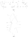
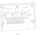
Fig. 1 is a schematic structural diagram of the back surface of the decorative plate provided in an embodiment of the present invention; -
Fig. 2 is a 3D schematic structural diagram of the double-side fastener inFig. 1 ; -
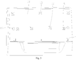
Fig. 3 is a front view of the handle element provided in an embodiment of the present invention; -
Fig. 4 is a back view of the handle element inFig. 3 ; -
Fig. 5 is an enlarged view of the double-side fastening hole inFig. 4 ; -
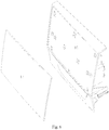
Fig. 6 is an exploded view of the handle provided in an embodiment of the present invention, showing the decorative plate inFig. 1 and the handle element inFig. 3 ; -
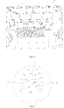
Fig. 7 is a back view of the handle inFig. 6 ; -
Fig. 8 is an enlarged view of the double-side fastening hole and the double-side fastener inFig. 7 in a fitted state; and -
Fig. 9 is a sectional view of the double-side fastening hole and the double-side fastener inFig. 7 in fitted state. - 1 - plate body; 2 - double-side fastener; 3 - fastening stub; 4 - protruding hook; 5 - front side surface; 6 - rear side surface; 7 - slope surface; 8 - triangular reinforcing plate; 9 - first single-side fastener; 10 - second single-side fastener; 11 - positioning stub; 12 - double-side fastening hole; 13 - insertion opening; 14 - fastening edge; 15 - single-side fastening hole; 16 - positioning hole; 17 - decorative plate; 18 - handle element.
- Hereunder some embodiments of the present invention will be detailed with reference to the accompanying drawings. It should be understood that the embodiments described here are only provided to describe and explain the present invention, but shall not be deemed as constituting any limitation to the present invention.
- As shown in
Figs. 1 and 2 , thedecorative plate 17 provided in the present invention comprises a plate body 1 provided with fasteners on its back surface opposite to its decorative surface, wherein, the fasteners comprise double-side fasteners 2, each of which includes afastening stub 3 that projects outwardly from the back surface and has opposite protrudinghooks 4 that are formed on opposite sides of thefastening stub 3 and protrude outwardly from the respective sides. - In the technical scheme described above, since the
fastening stubs 3 directly project from the decorative plate and eachfastening stub 3 has opposite protrudinghooks 4 that are formed on two opposite sides of thefastening stub 3 and protrude outwardly from respective sides, any other supporting member is avoided between the protrudinghooks 4 and the decorative plate, except thefastening stubs 3; besides, thefastening stubs 3 directly project outwardly from the decorative plate, e.g., integrally, and thereby the strength of thefastening stubs 3 is improved significantly. In that way, when the decorative plate is assembled, thefastening stubs 3 are inserted into a mounting base, e.g., into corresponding double-side fastening holes in a handle element described below, so that theprotruding hooks 4 push aside two opposite fastening edges in each of the double-side fastening holes and are snap-fitted in the double-side fastening holes; in such a way, the double-side fasteners have smaller deformation, and are not easy to break, subject to smaller insertion resistance, and easy to assemble. Herein, it should be understood: in the decorative plate in the present invention, theprotruding hooks 4 on the two opposite sides of the fasteningstub 3 may be in different structural forms. For example, in a structural form, theprotruding hooks 4 may be semi-circular or hemi-spherical; or, in a preferred structural form, as shown inFig. 2 , afront side surface 5 of the protruding hook 4 (i.e., the top part of the drawing inFig. 2 ) forms a slope surface, so that two oppositefront side surfaces 5 form a splayed shape, and thereby the slopefront side surfaces 5 can push asidefastening edges 14 more easily when the double-side fastener is fitted with a double-side fastening hole described below. - Furthermore, as shown in
Fig. 2 , a rear side surface 6 of the protruding hook 4 (i.e., the bottom part of the drawing inFig. 2 ) form a slope surface, so that two opposite rear side surfaces 6 form an inverted splayed shape, and thereby the slope rear side surfaces 6 contact with thefastening edges 14 in a larger area so as to improve the stability of the snap-fitting when the double-side fastener and the double-side fastening hole are fitted with each other; besides, the double-side fastener can be disengaged from the double-side fastening hole easily when the decorative plate is to be removed from the mounting base, owing to a guiding effect of the slope rear side surfaces 6. - In addition, the
opposite protruding hooks 4 may be formed on the middle part or upper part of thefastening stub 3; alternatively, as shown inFig. 2 , preferably theprotruding hooks 4 are formed on the front end part of thefastening stub 3 to take full advantage of the length of thefastening stub 3 and avoid excessive overall length of the double-side fastener. - Furthermore, for the convenience of snap-fitting and releasing, preferably, as shown in
Fig. 2 , thefront side surface 5 and the rear side surface 6 of eachprotruding hook 4 are connected via a convex arc surface; in that way, the most producing point of theprotruding hook 4 can pass by the fastening edge more easily in the snap-fitting or releasing process. - In addition, to facilitate the
protruding hook 4 to wedge into the space between the two fastening edges, preferably, as shown inFig. 2 , the front end face of thefastening stub 3 forms a convex arc surface to connect the two oppositefront side surfaces 5 on the two side in an arc form. Thus, the arc surface enters into the space between the two fastening edges first, and guides the slopefront side surfaces 5 to push aside the two fastening edges. - Furthermore, as shown in
Figs. 1 and 2 , to improve the structural strength of thefastening stub 3 and improve the stability of fitting between the double-side fastener and the double-side fastening hole, preferably, atriangular reinforcing plate 8 comprising straight-edge surfaces and a slope surface 7 is connected between each of the two opposite sides of thefastening stub 3 and the back surface, wherein, the two straight-edge surfaces of thetriangular reinforcing plate 8 is connected with the side and the back surface respectively. Since the slope surfaces 7 are exposed, as shown inFig. 9 , when the double-side fastener is inserted and fitted in the double-side fastening hole, the twotriangular reinforcing plates 8 will be accommodated in the space between the twofastening edges 14, so that the space attains a spatial positioning effect for the two triangular reinforcing plates; more preferably, the slope surfaces 7 will abut against the slope surfaces of thefastening edges 14 arranged in a slope manner, so as to further improve positioning reliability. - Furthermore, the quantity of the double-
side fasteners 2 may be selected according to the actual requirement. For example, as shown inFig. 1 , a plurality of double-side fasteners 2 are provided and arranged at an interval along the edge on one side of the back surface in the length direction of the decorative plate. Thus, the edge on the side of the decorative plate is stably and reliably fitted via the plurality of double-side fasteners 2 arranged at an interval. - Furthermore, as shown in
Fig. 1 , to improve assembling reliability of the decorative plate, preferably, the fasteners comprise a plurality of first single-side fasteners 9, which are arranged at an interval along the edge on the other side of the back surface in the length direction of the decorative plate. Of course, single-side fastening holes 15 that can be fitted with the first single-side fasteners 9 are formed in the mounting base, e.g., the handle element described below. In addition, the first single-side fasteners 9 may comprise stubs and fastening hooks projecting from the stubs. - Furthermore, at least one first single-side fastener 9 in the middle area of the edge on the other side of the decorative plate comprises a connecting stub that projects from the plate body and a positioning and fastening edge that projects outwardly from a front end of the connecting stub towards the edge on the other side, wherein the positioning and fastening edge extends obliquely towards the back surface of the plate body to form an included angle smaller than 90° (preferably slightly smaller than 90°, e.g., 85-88°) between the positioning and fastening edge and the connecting stub, and is configured to be fastened and positioned in a positioning space on the periphery of a positioning hole in the mounting base. Thus, when the decorative plate is assembled, the positioning and fastening edges can be inserted downwards into the mounting base, e.g., into single-side fastening holes 15 in the handle element described below, so that the periphery of each of the single-side fastening holes 15 is positioned in a positioning space to attain a pre-positioning effect, to facilitate the operator to insert the decorative plate to the correct position easily.
- Furthermore, as shown in
Fig. 1 , the fasteners comprisepositioning stubs 11 and second single-side fasteners 10, wherein, the positioning stubs 11 are formed on the edges at the two ends of the back surface in the length direction of the decorative plate, so as to achieve more stable and reliable positioning during the assembling. - In addition, at least two second single-
side fasteners 10 are arranged at an interval in the length direction of the decorative plate between the positioning stubs 11 at the two ends; thus, the reliability of connection on the edges at the two ends of the decorative plate is improved by means of the fitting between the second single-side fasteners 10 and the corresponding single-side fastening holes. - In addition, at least two double-
side fasteners 2 are arranged at an interval in the length direction of the decorative plate between the positioning stubs 11 at the two ends; thus, as described above, the reliability of connection in the middle area of the decorative plate is improved by means of said at least two double-side fasteners 2. - Of course, in the decorative plate in the present invention, the positional relation among the fasteners is not limited to the positional relation described above, and may be adjusted according to the actual requirement. For example, as shown in
Fig. 1 , at least two double-side fasteners 2 are arranged between the second single-side fasteners 10 between the positioning stubs 11 at the two ends. - In addition, the orientation of the fastening hooks of the first single-side fasteners 9 are reversed to the orientation of the fastening hooks of the second single-
side fasteners 10, to realize snap-fitting in which the members abut against each other in different directions. - In addition, the present invention provides a
handle element 18. As shown inFigs. 3 ,4 and 5 , thehandle element 18 comprises a plate body, which has fastening holes that are formed on an external surface (i.e., front surface) of the plate body for mounting a decorative plate and configured to snap-fit with fasteners on the decorative plate, wherein, the fastening holes comprise double-side fastening holes 12 configured to fit with double-side fasteners on the decorative plate, and wherein the double-side fastening hole 12 comprises aninsertion opening 13, which has fastening edges 14 that are formed on two opposite sides of theinsertion opening 13, extend towards the interior of the plate body, and configured to fit with the protrudinghooks 4 of corresponding double-side fastener. Thus, as described above, when anydecorative plate 17 described above is fitted with thehandle element 18, thefastening stubs 3 are inserted into corresponding double-side fastening holes 12 in thehandle element 18, so that the protrudinghooks 4 push aside the two opposite fastening edges 14 in each of the double-side fastening holes 12 and are snap-fitted in the double-side fastening holes 12; in that way, the double-side fasteners and the fastening edges 14 have smaller deformation and are not easy to break; besides, the double-side fasteners are subject to smaller insertion resistance and easy to assemble. - Of course, in the handle element in the present invention, the two
fastening edges 14 in the double-side fastening hole may be in different structural forms. For example, they may be elastic plates extending straightly and levelly; alternatively, as shown inFig. 5 , two opposite fastening edges 14 extend obliquely to get closer to each other to form a splayed shape; as shown inFig. 9 , with such a structure, the double-side fastener can be snap-fitted more easily. Besides, as shown inFig. 9 , when the double-side fastener is inserted and fitted in the double-side fastening hole, the two triangular reinforcingplates 8 will be accommodated in the space between the twofastening edges 14, so that the space attain a spatial positioning effect for the two triangular reinforcing plates; more preferably, the slope surfaces 7 will abut against the slope surfaces of the fastening edges 14 arranged in a slope manner, so as to further improve positioning reliability. - In addition, the fastening holes further comprise single-side fastening holes 15 configured to snap-fit with single-side fasteners on the decorative plate and positioning holes 16 configured to fit with positioning stubs on the decorative plate. Of course, a single fastening edge is formed in the single-
side fastening hole 15. - Furthermore, the present invention provides a handle. As shown in
Figs. 6-9 , the handle comprises anyhandle element 18 described above and anydecorative plate 17 described above, wherein, the fasteners on thedecorative plate 17 are fitted with the fastening holes in the handle element. - Specifically, the
fastening stubs 3 of the double-side fasteners 2 on the decorative plate penetrate into theinsertion openings 13 of the double-side fastening holes 12 in the handle element, so that the opposite protruding hooks 4 are snap-fitted with the opposite fastening edges 14. - In that way, the double-side fasteners and the fastening edges 14 have smaller deformation and are not easy to break; in addition, the double-side fasteners are subject to smaller insertion resistance and easy to assemble.
- Furthermore, in a case that a triangular reinforcing
plate 8 comprising straight-edge surfaces and an slope surface 7 is connected between the two opposite sides of thefastening stub 3 and the back surface and the two opposite fastening edges 14 extend obliquely to get closer to each other so that they form a splayed shape, as shown inFig. 9 , the two triangular reinforcingplates 8 are accommodated in a space between the two fastening edges 14. That is to say, when the double-side fastener is inserted and fitted in the double-side fastening hole, the two triangular reinforcingplates 8 will be accommodated in the space between the twofastening edges 14, so that the space attains a spatial positioning effect for the two triangular reinforcing plates; more preferably, the slope surfaces 7 will abut against the slope surfaces of the fastening edges 14 arranged in a slope manner, so as to further improve positioning reliability. - Furthermore, the present invention provides a washing product accommodation box, which comprises a box body and a drawer that are fitted with each other, wherein, a front end face of the drawer is provided with any handle described above. Thus, as described above, the service life and overall quality of the washing product accommodation box are significantly improved.
- At last, the present invention provides a washing machine, such as a drum-type washing machine, which is provided with the washing product accommodation box described above. Thus, the overall quality of the washing machine is improved significantly.
- While the present invention is described above in detail in some preferred embodiments with reference to the accompanying drawings, the present invention is not limited to those embodiments. Various simple variations may be made to the technical scheme in the present invention, including combinations of the specific technical features in any appropriate form, within the scope of the technical ideal of the present invention. To avoid unnecessary repetition, the possible combinations are not described specifically in the present invention. However, such simple variations and combinations shall also be deemed as having been disclosed and falling in the scope of protection of the present invention.
Claims (15)
- A decorative plate, comprising a plate body (1) provided with fasteners on its back surface opposite to its decorative surface, wherein, each of the fasteners comprises a double-side fastener (2) including a fastening stub (3) that projects outwardly from the back surface and has opposite protruding hooks (4) that are formed on opposite sides of the fastening stub (3) and protrude outwardly from the respective sides.
- The decorative plate according to claim 1, wherein, a front side surface (5) of the protruding hook (4) forms a slope surface, so that two opposite front side surfaces (5) on the two sides form a splayed shape;
preferably, a rear side surface (6) of the protruding hook (4) forms a slope surface, so that two opposite rear side surfaces (6) on the two sides form an inverted splayed shape;
preferably, the opposite protruding hooks (4) are formed on a front end of the fastening stub (3). - The decorative plate according to claim 2, wherein, the front side surface (5) and the rear side surface (6) of each protruding hook (4) are connected via a convex arc surface;
a front end face of the fastening stub (3) forms a convex arc surface and connects the two opposite front side surfaces (5) on the two sides in an arc form. - The decorative plate according to claim 1, wherein, a triangular reinforcing plate (8) that comprises straight-edge surfaces and a slope surface (7) is connected between each of the two opposite sides of the fastening stub (3) and the back surface, and wherein the two straight-edge surfaces of the triangular reinforcing plate (8) are connected with the side and the back surface respectively.
- The decorative plate according to any of claims 1-4, wherein, a plurality of double-side fasteners (2) are provided and arranged at an interval along the edge on one side of the back surface in the length direction of the decorative plate.
- The decorative plate according to claim 5, wherein, the fasteners comprise a plurality of first single-side fasteners (9), which are arranged at an interval along the edge on the other side of the back surface in the length direction of the decorative plate.
- The decorative plate according to claim 6, wherein, at least one first single-side fastener (9) in the middle area of the edge on the other side of the decorative plate comprises a connecting stub that projects from the plate body and a positioning and fastening edge that projects outwardly from a front end of the connecting stub towards the edge on the other side, wherein the positioning and fastening edge extends obliquely towards the back surface of the plate body to form an included angle smaller than 90° between the positioning and fastening edge and the connecting stub, and is configured to be fastened and positioned in a positioning space on the periphery of a positioning hole in the mounting base.
- The decorative plate according to claim 6, wherein, the fasteners comprise positioning stubs (11) and second single-side fasteners (10), wherein,
the positioning stubs (11) are formed on the edges of two ends of the back surface in the length direction of the decorative plate;
at least two second single-side fasteners (10) are arranged at an interval in the length direction of the decorative plate between the positioning stubs (11) at the two ends;
at least two double-side fasteners (2) are arranged at an interval in the length direction of the decorative plate between the positioning stubs (11) at the two ends. - The decorative plate according to claim 8, wherein, said at least two double-side fasteners (2) are positioned between said second single-side fasteners (10) between the positioning stubs (11) at the two ends;
the orientation of the fastening hook of said first single-side fastener (9) is reversed to the orientation of the fastening hook of the second single-side fastener (10). - A handle element, comprising a plate body, which has fastening holes formed on an external surface of the plate body for mounting a decorative plate and configured to fit with fasteners on the decorative plate, wherein, each of the fastening holes comprises a double-side fastening hole (12) configured to fit with a double-side fastener on the decorative plate, wherein,
the double-side fastening hole (12) comprises an insertion opening (13), which has fastening edges (14) that are formed on two opposite sides of the insertion opening (13), extend towards the interior of the plate body, and are configured to snap-fit with the protruding hooks (4) of corresponding double-side fastener. - The handle element according to claim 10, wherein, the two opposite fastening edges (14) extend obliquely to get closer to each other, so that they form a splayed shape;
the fastening holes comprise single-side fastening holes (15) configured to snap-fit with single-side fasteners on the decorative plate and positioning holes (16) configured to fit with positioning stubs on the decorative plate. - A handle, comprising the handle element (18) according to claim 10 or 11 and the decorative plate (17) according to any of claims 1-11, wherein, the fasteners on the decorative plate are fitted with the fastening holes in the handle element, wherein,
the fastening stubs (3) of the double-side fasteners (2) on the decorative plate penetrate into the insertion openings (13) of the double-side fastening holes (12) in the handle element, so that the opposite protruding hooks (4) are snap-fitted with the opposite fastening edges (14). - The handle according to claim 12, wherein, in a case that a triangular reinforcing plate (8) comprising straight-edge surfaces and an slope surface (7) is connected between each of the two opposite sides of the fastening stub (3) and the back surface, and said two opposite fastening edges (14) extend obliquely to get closer to each other so that they form a splayed shape:the two triangular reinforcing plates (8) are accommodated in a space between the two fastening edges (14).
- A washing product accommodation box, comprising a box body and a drawer that are fitted with each other, wherein, the handle according to claim 12 or 13 is provided on a front end face of the drawer.
- A washing machine provided with the washing product accommodation box according to claim 14.
Applications Claiming Priority (1)
| Application Number | Priority Date | Filing Date | Title |
|---|---|---|---|
| CN201810036419.0A CN108018677B (en) | 2018-01-15 | 2018-01-15 | Decorative plate, handle piece, handle, washing article accommodating box and washing machine |
Publications (2)
| Publication Number | Publication Date |
|---|---|
| EP3511464A1 true EP3511464A1 (en) | 2019-07-17 |
| EP3511464B1 EP3511464B1 (en) | 2022-02-02 |
Family
ID=62072687
Family Applications (1)
| Application Number | Title | Priority Date | Filing Date |
|---|---|---|---|
| EP18197653.1A Active EP3511464B1 (en) | 2018-01-15 | 2018-09-28 | Washing machine and components therefor |
Country Status (2)
| Country | Link |
|---|---|
| EP (1) | EP3511464B1 (en) |
| CN (1) | CN108018677B (en) |
Cited By (2)
| Publication number | Priority date | Publication date | Assignee | Title |
|---|---|---|---|---|
| EP4060112A1 (en) * | 2021-03-19 | 2022-09-21 | BSH Hausgeräte GmbH | Closing handling device |
| EP4091784A1 (en) * | 2021-05-14 | 2022-11-23 | BSH Hausgeräte GmbH | Clothes treating device including drawer panel |
Families Citing this family (3)
| Publication number | Priority date | Publication date | Assignee | Title |
|---|---|---|---|---|
| CN111156206A (en) * | 2020-01-19 | 2020-05-15 | 珠海格力电器股份有限公司 | Fan base assembly and bladeless fan |
| CN114000322A (en) * | 2020-07-28 | 2022-02-01 | 无锡小天鹅电器有限公司 | Handle and clothes treatment equipment |
| CN114212345B (en) * | 2021-12-14 | 2025-07-11 | 成都杰润智能包装有限公司 | A detachable environmentally friendly packaging bracket and packaging box thereof |
Citations (5)
| Publication number | Priority date | Publication date | Assignee | Title |
|---|---|---|---|---|
| US5659927A (en) * | 1994-12-12 | 1997-08-26 | Silvatrim Associates | Refrigerator door handle |
| EP0943284A1 (en) * | 1998-03-20 | 1999-09-22 | Whirlpool Corporation | Household device with a casing made from prefabricated sheet metal wall panels, in particular a washing machine or dishwasher |
| US20070188059A1 (en) * | 2006-02-15 | 2007-08-16 | Maytag Corp. | Kitchen appliance having floating glass panel |
| WO2017059907A1 (en) * | 2015-10-08 | 2017-04-13 | Arcelik Anonim Sirketi | Drawer assembly for a laundry machine |
| CN106884282A (en) * | 2015-12-16 | 2017-06-23 | 青岛海尔滚筒洗衣机有限公司 | A kind of detergent box and roller washing machine |
Family Cites Families (7)
| Publication number | Priority date | Publication date | Assignee | Title |
|---|---|---|---|---|
| CN201439328U (en) * | 2009-07-30 | 2010-04-21 | 宁波信泰机械有限公司 | Fastener installing decorative sheet bright wisp on automobile tail part |
| CN202627261U (en) * | 2012-05-09 | 2012-12-26 | 北京竣雅筑景工程科技发展有限公司 | Buckle connecting structure applied in finished product partition system |
| CN203533837U (en) * | 2013-11-08 | 2014-04-09 | 珠海格力电器股份有限公司 | Air conditioner casing and have its air conditioner |
| CN204161252U (en) * | 2014-10-22 | 2015-02-18 | 东风汽车公司 | A kind of automobile triangular trim panel mounting structure |
| CN204494747U (en) * | 2015-04-17 | 2015-07-22 | 宁波吉通信息技术有限公司 | Side decorative panel |
| CN105465119A (en) * | 2015-12-21 | 2016-04-06 | 珠海格力电器股份有限公司 | Buckle structure and air conditioner panel decorative board |
| CN205468871U (en) * | 2016-03-16 | 2016-08-17 | 奇瑞汽车股份有限公司 | Mounting structure of automobile decoration strip |
-
2018
- 2018-01-15 CN CN201810036419.0A patent/CN108018677B/en active Active
- 2018-09-28 EP EP18197653.1A patent/EP3511464B1/en active Active
Patent Citations (5)
| Publication number | Priority date | Publication date | Assignee | Title |
|---|---|---|---|---|
| US5659927A (en) * | 1994-12-12 | 1997-08-26 | Silvatrim Associates | Refrigerator door handle |
| EP0943284A1 (en) * | 1998-03-20 | 1999-09-22 | Whirlpool Corporation | Household device with a casing made from prefabricated sheet metal wall panels, in particular a washing machine or dishwasher |
| US20070188059A1 (en) * | 2006-02-15 | 2007-08-16 | Maytag Corp. | Kitchen appliance having floating glass panel |
| WO2017059907A1 (en) * | 2015-10-08 | 2017-04-13 | Arcelik Anonim Sirketi | Drawer assembly for a laundry machine |
| CN106884282A (en) * | 2015-12-16 | 2017-06-23 | 青岛海尔滚筒洗衣机有限公司 | A kind of detergent box and roller washing machine |
Cited By (2)
| Publication number | Priority date | Publication date | Assignee | Title |
|---|---|---|---|---|
| EP4060112A1 (en) * | 2021-03-19 | 2022-09-21 | BSH Hausgeräte GmbH | Closing handling device |
| EP4091784A1 (en) * | 2021-05-14 | 2022-11-23 | BSH Hausgeräte GmbH | Clothes treating device including drawer panel |
Also Published As
| Publication number | Publication date |
|---|---|
| EP3511464B1 (en) | 2022-02-02 |
| CN108018677A (en) | 2018-05-11 |
| CN108018677B (en) | 2023-08-15 |
Similar Documents
| Publication | Publication Date | Title |
|---|---|---|
| EP3511464B1 (en) | Washing machine and components therefor | |
| US8083299B2 (en) | Housing for a front-loading laundry appliance | |
| US9005371B2 (en) | Domestic appliance, in particular dishwasher | |
| CN106884282B (en) | Detergent box and drum washing machine | |
| KR20150004201A (en) | Sliding Door Handle | |
| KR101162206B1 (en) | fixing structure of front cover and side-deco for drum-type washing machine | |
| CN205655575U (en) | A frame, Refrigerator door and refrigerator for refrigerator door | |
| CN216074418U (en) | Connecting frame, clothes treating device and clothes treating equipment | |
| CN109423834B (en) | Drum washing machine | |
| US20190247086A1 (en) | Needle groove body, puncture frame body and puncture frame | |
| CN104296474B (en) | Shell component and refrigerator counter door with same | |
| CN210227267U (en) | Assembled makeup brush holder and makeup brush | |
| CN110870731B (en) | Dishwasher with control panel and assembly method of control panel | |
| CN109811516B (en) | Front maintenance drum washing machine and disassembling method thereof | |
| KR20020048575A (en) | structure for coupling top plate by holder in drum type washing machine | |
| WO2012032007A1 (en) | A domestic appliance comprising top plate | |
| CN212720417U (en) | Storage structure, door structure and refrigeration equipment | |
| CN210377222U (en) | Screwless display device shell and display device | |
| JPH0611778U (en) | Passage checker for pachinko machines | |
| ITMI952533A1 (en) | HOUSEHOLD APPLIANCE WITH A FRAME | |
| CN108670161B (en) | Control panel box and dishwasher | |
| EP2554735A1 (en) | A top-loading washing machine comprising a pivoting lid | |
| CN221450483U (en) | Oven with a baking oven | |
| CN110396800A (en) | Washing liquid box subassembly and washing machine | |
| CN217852841U (en) | Door body assembly for cleaning machine and cleaning machine |
Legal Events
| Date | Code | Title | Description |
|---|---|---|---|
| PUAI | Public reference made under article 153(3) epc to a published international application that has entered the european phase |
Free format text: ORIGINAL CODE: 0009012 |
|
| STAA | Information on the status of an ep patent application or granted ep patent |
Free format text: STATUS: REQUEST FOR EXAMINATION WAS MADE |
|
| 17P | Request for examination filed |
Effective date: 20180928 |
|
| AK | Designated contracting states |
Kind code of ref document: A1 Designated state(s): AL AT BE BG CH CY CZ DE DK EE ES FI FR GB GR HR HU IE IS IT LI LT LU LV MC MK MT NL NO PL PT RO RS SE SI SK SM TR |
|
| AX | Request for extension of the european patent |
Extension state: BA ME |
|
| RAP1 | Party data changed (applicant data changed or rights of an application transferred) |
Owner name: WUXI LITTLE SWAN ELECTRIC CO., LTD. |
|
| RAP1 | Party data changed (applicant data changed or rights of an application transferred) |
Owner name: WUXI LITTLE SWAN ELECTRIC CO., LTD. |
|
| GRAP | Despatch of communication of intention to grant a patent |
Free format text: ORIGINAL CODE: EPIDOSNIGR1 |
|
| STAA | Information on the status of an ep patent application or granted ep patent |
Free format text: STATUS: GRANT OF PATENT IS INTENDED |
|
| INTG | Intention to grant announced |
Effective date: 20211116 |
|
| GRAS | Grant fee paid |
Free format text: ORIGINAL CODE: EPIDOSNIGR3 |
|
| GRAA | (expected) grant |
Free format text: ORIGINAL CODE: 0009210 |
|
| STAA | Information on the status of an ep patent application or granted ep patent |
Free format text: STATUS: THE PATENT HAS BEEN GRANTED |
|
| AK | Designated contracting states |
Kind code of ref document: B1 Designated state(s): AL AT BE BG CH CY CZ DE DK EE ES FI FR GB GR HR HU IE IS IT LI LT LU LV MC MK MT NL NO PL PT RO RS SE SI SK SM TR |
|
| REG | Reference to a national code |
Ref country code: GB Ref legal event code: FG4D |
|
| REG | Reference to a national code |
Ref country code: CH Ref legal event code: EP Ref country code: AT Ref legal event code: REF Ref document number: 1466617 Country of ref document: AT Kind code of ref document: T Effective date: 20220215 |
|
| REG | Reference to a national code |
Ref country code: DE Ref legal event code: R096 Ref document number: 602018030344 Country of ref document: DE |
|
| REG | Reference to a national code |
Ref country code: IE Ref legal event code: FG4D |
|
| REG | Reference to a national code |
Ref country code: LT Ref legal event code: MG9D |
|
| REG | Reference to a national code |
Ref country code: NL Ref legal event code: MP Effective date: 20220202 |
|
| REG | Reference to a national code |
Ref country code: AT Ref legal event code: MK05 Ref document number: 1466617 Country of ref document: AT Kind code of ref document: T Effective date: 20220202 |
|
| PG25 | Lapsed in a contracting state [announced via postgrant information from national office to epo] |
Ref country code: SE Free format text: LAPSE BECAUSE OF FAILURE TO SUBMIT A TRANSLATION OF THE DESCRIPTION OR TO PAY THE FEE WITHIN THE PRESCRIBED TIME-LIMIT Effective date: 20220202 Ref country code: RS Free format text: LAPSE BECAUSE OF FAILURE TO SUBMIT A TRANSLATION OF THE DESCRIPTION OR TO PAY THE FEE WITHIN THE PRESCRIBED TIME-LIMIT Effective date: 20220202 Ref country code: PT Free format text: LAPSE BECAUSE OF FAILURE TO SUBMIT A TRANSLATION OF THE DESCRIPTION OR TO PAY THE FEE WITHIN THE PRESCRIBED TIME-LIMIT Effective date: 20220602 Ref country code: NO Free format text: LAPSE BECAUSE OF FAILURE TO SUBMIT A TRANSLATION OF THE DESCRIPTION OR TO PAY THE FEE WITHIN THE PRESCRIBED TIME-LIMIT Effective date: 20220502 Ref country code: NL Free format text: LAPSE BECAUSE OF FAILURE TO SUBMIT A TRANSLATION OF THE DESCRIPTION OR TO PAY THE FEE WITHIN THE PRESCRIBED TIME-LIMIT Effective date: 20220202 Ref country code: LT Free format text: LAPSE BECAUSE OF FAILURE TO SUBMIT A TRANSLATION OF THE DESCRIPTION OR TO PAY THE FEE WITHIN THE PRESCRIBED TIME-LIMIT Effective date: 20220202 Ref country code: HR Free format text: LAPSE BECAUSE OF FAILURE TO SUBMIT A TRANSLATION OF THE DESCRIPTION OR TO PAY THE FEE WITHIN THE PRESCRIBED TIME-LIMIT Effective date: 20220202 Ref country code: ES Free format text: LAPSE BECAUSE OF FAILURE TO SUBMIT A TRANSLATION OF THE DESCRIPTION OR TO PAY THE FEE WITHIN THE PRESCRIBED TIME-LIMIT Effective date: 20220202 Ref country code: BG Free format text: LAPSE BECAUSE OF FAILURE TO SUBMIT A TRANSLATION OF THE DESCRIPTION OR TO PAY THE FEE WITHIN THE PRESCRIBED TIME-LIMIT Effective date: 20220502 |
|
| PG25 | Lapsed in a contracting state [announced via postgrant information from national office to epo] |
Ref country code: PL Free format text: LAPSE BECAUSE OF FAILURE TO SUBMIT A TRANSLATION OF THE DESCRIPTION OR TO PAY THE FEE WITHIN THE PRESCRIBED TIME-LIMIT Effective date: 20220202 Ref country code: LV Free format text: LAPSE BECAUSE OF FAILURE TO SUBMIT A TRANSLATION OF THE DESCRIPTION OR TO PAY THE FEE WITHIN THE PRESCRIBED TIME-LIMIT Effective date: 20220202 Ref country code: GR Free format text: LAPSE BECAUSE OF FAILURE TO SUBMIT A TRANSLATION OF THE DESCRIPTION OR TO PAY THE FEE WITHIN THE PRESCRIBED TIME-LIMIT Effective date: 20220503 Ref country code: FI Free format text: LAPSE BECAUSE OF FAILURE TO SUBMIT A TRANSLATION OF THE DESCRIPTION OR TO PAY THE FEE WITHIN THE PRESCRIBED TIME-LIMIT Effective date: 20220202 Ref country code: AT Free format text: LAPSE BECAUSE OF FAILURE TO SUBMIT A TRANSLATION OF THE DESCRIPTION OR TO PAY THE FEE WITHIN THE PRESCRIBED TIME-LIMIT Effective date: 20220202 |
|
| PG25 | Lapsed in a contracting state [announced via postgrant information from national office to epo] |
Ref country code: IS Free format text: LAPSE BECAUSE OF FAILURE TO SUBMIT A TRANSLATION OF THE DESCRIPTION OR TO PAY THE FEE WITHIN THE PRESCRIBED TIME-LIMIT Effective date: 20220602 |
|
| PG25 | Lapsed in a contracting state [announced via postgrant information from national office to epo] |
Ref country code: SM Free format text: LAPSE BECAUSE OF FAILURE TO SUBMIT A TRANSLATION OF THE DESCRIPTION OR TO PAY THE FEE WITHIN THE PRESCRIBED TIME-LIMIT Effective date: 20220202 Ref country code: SK Free format text: LAPSE BECAUSE OF FAILURE TO SUBMIT A TRANSLATION OF THE DESCRIPTION OR TO PAY THE FEE WITHIN THE PRESCRIBED TIME-LIMIT Effective date: 20220202 Ref country code: RO Free format text: LAPSE BECAUSE OF FAILURE TO SUBMIT A TRANSLATION OF THE DESCRIPTION OR TO PAY THE FEE WITHIN THE PRESCRIBED TIME-LIMIT Effective date: 20220202 Ref country code: EE Free format text: LAPSE BECAUSE OF FAILURE TO SUBMIT A TRANSLATION OF THE DESCRIPTION OR TO PAY THE FEE WITHIN THE PRESCRIBED TIME-LIMIT Effective date: 20220202 Ref country code: DK Free format text: LAPSE BECAUSE OF FAILURE TO SUBMIT A TRANSLATION OF THE DESCRIPTION OR TO PAY THE FEE WITHIN THE PRESCRIBED TIME-LIMIT Effective date: 20220202 Ref country code: CZ Free format text: LAPSE BECAUSE OF FAILURE TO SUBMIT A TRANSLATION OF THE DESCRIPTION OR TO PAY THE FEE WITHIN THE PRESCRIBED TIME-LIMIT Effective date: 20220202 |
|
| REG | Reference to a national code |
Ref country code: DE Ref legal event code: R097 Ref document number: 602018030344 Country of ref document: DE |
|
| PG25 | Lapsed in a contracting state [announced via postgrant information from national office to epo] |
Ref country code: AL Free format text: LAPSE BECAUSE OF FAILURE TO SUBMIT A TRANSLATION OF THE DESCRIPTION OR TO PAY THE FEE WITHIN THE PRESCRIBED TIME-LIMIT Effective date: 20220202 |
|
| PLBE | No opposition filed within time limit |
Free format text: ORIGINAL CODE: 0009261 |
|
| STAA | Information on the status of an ep patent application or granted ep patent |
Free format text: STATUS: NO OPPOSITION FILED WITHIN TIME LIMIT |
|
| 26N | No opposition filed |
Effective date: 20221103 |
|
| PG25 | Lapsed in a contracting state [announced via postgrant information from national office to epo] |
Ref country code: SI Free format text: LAPSE BECAUSE OF FAILURE TO SUBMIT A TRANSLATION OF THE DESCRIPTION OR TO PAY THE FEE WITHIN THE PRESCRIBED TIME-LIMIT Effective date: 20220202 |
|
| PG25 | Lapsed in a contracting state [announced via postgrant information from national office to epo] |
Ref country code: MC Free format text: LAPSE BECAUSE OF FAILURE TO SUBMIT A TRANSLATION OF THE DESCRIPTION OR TO PAY THE FEE WITHIN THE PRESCRIBED TIME-LIMIT Effective date: 20220202 |
|
| REG | Reference to a national code |
Ref country code: CH Ref legal event code: PL |
|
| GBPC | Gb: european patent ceased through non-payment of renewal fee |
Effective date: 20220928 |
|
| REG | Reference to a national code |
Ref country code: BE Ref legal event code: MM Effective date: 20220930 |
|
| PG25 | Lapsed in a contracting state [announced via postgrant information from national office to epo] |
Ref country code: LU Free format text: LAPSE BECAUSE OF NON-PAYMENT OF DUE FEES Effective date: 20220928 |
|
| PG25 | Lapsed in a contracting state [announced via postgrant information from national office to epo] |
Ref country code: LI Free format text: LAPSE BECAUSE OF NON-PAYMENT OF DUE FEES Effective date: 20220930 Ref country code: IT Free format text: LAPSE BECAUSE OF FAILURE TO SUBMIT A TRANSLATION OF THE DESCRIPTION OR TO PAY THE FEE WITHIN THE PRESCRIBED TIME-LIMIT Effective date: 20220202 Ref country code: IE Free format text: LAPSE BECAUSE OF NON-PAYMENT OF DUE FEES Effective date: 20220928 Ref country code: FR Free format text: LAPSE BECAUSE OF NON-PAYMENT OF DUE FEES Effective date: 20220930 Ref country code: CH Free format text: LAPSE BECAUSE OF NON-PAYMENT OF DUE FEES Effective date: 20220930 |
|
| PG25 | Lapsed in a contracting state [announced via postgrant information from national office to epo] |
Ref country code: BE Free format text: LAPSE BECAUSE OF NON-PAYMENT OF DUE FEES Effective date: 20220930 |
|
| PG25 | Lapsed in a contracting state [announced via postgrant information from national office to epo] |
Ref country code: GB Free format text: LAPSE BECAUSE OF NON-PAYMENT OF DUE FEES Effective date: 20220928 |
|
| PG25 | Lapsed in a contracting state [announced via postgrant information from national office to epo] |
Ref country code: HU Free format text: LAPSE BECAUSE OF FAILURE TO SUBMIT A TRANSLATION OF THE DESCRIPTION OR TO PAY THE FEE WITHIN THE PRESCRIBED TIME-LIMIT; INVALID AB INITIO Effective date: 20180928 |
|
| PG25 | Lapsed in a contracting state [announced via postgrant information from national office to epo] |
Ref country code: CY Free format text: LAPSE BECAUSE OF FAILURE TO SUBMIT A TRANSLATION OF THE DESCRIPTION OR TO PAY THE FEE WITHIN THE PRESCRIBED TIME-LIMIT Effective date: 20220202 |
|
| PG25 | Lapsed in a contracting state [announced via postgrant information from national office to epo] |
Ref country code: MK Free format text: LAPSE BECAUSE OF FAILURE TO SUBMIT A TRANSLATION OF THE DESCRIPTION OR TO PAY THE FEE WITHIN THE PRESCRIBED TIME-LIMIT Effective date: 20220202 |
|
| PG25 | Lapsed in a contracting state [announced via postgrant information from national office to epo] |
Ref country code: MT Free format text: LAPSE BECAUSE OF FAILURE TO SUBMIT A TRANSLATION OF THE DESCRIPTION OR TO PAY THE FEE WITHIN THE PRESCRIBED TIME-LIMIT Effective date: 20220202 |
|
| PGFP | Annual fee paid to national office [announced via postgrant information from national office to epo] |
Ref country code: DE Payment date: 20250923 Year of fee payment: 8 |
|
| PG25 | Lapsed in a contracting state [announced via postgrant information from national office to epo] |
Ref country code: TR Free format text: LAPSE BECAUSE OF FAILURE TO SUBMIT A TRANSLATION OF THE DESCRIPTION OR TO PAY THE FEE WITHIN THE PRESCRIBED TIME-LIMIT Effective date: 20220202 |