EP3511316A1 - Aryldiamine compound and organic electroluminescent element - Google Patents
Aryldiamine compound and organic electroluminescent element Download PDFInfo
- Publication number
- EP3511316A1 EP3511316A1 EP17848837.5A EP17848837A EP3511316A1 EP 3511316 A1 EP3511316 A1 EP 3511316A1 EP 17848837 A EP17848837 A EP 17848837A EP 3511316 A1 EP3511316 A1 EP 3511316A1
- Authority
- EP
- European Patent Office
- Prior art keywords
- group
- formula
- carbon atoms
- bonded
- different positions
- Prior art date
- Legal status (The legal status is an assumption and is not a legal conclusion. Google has not performed a legal analysis and makes no representation as to the accuracy of the status listed.)
- Granted
Links
- 0 C*c(cc(cc1)N[Al])c1C1=C*C(C*)C=C1 Chemical compound C*c(cc(cc1)N[Al])c1C1=C*C(C*)C=C1 0.000 description 2
Images


Classifications
-
- C—CHEMISTRY; METALLURGY
- C07—ORGANIC CHEMISTRY
- C07C—ACYCLIC OR CARBOCYCLIC COMPOUNDS
- C07C211/00—Compounds containing amino groups bound to a carbon skeleton
- C07C211/43—Compounds containing amino groups bound to a carbon skeleton having amino groups bound to carbon atoms of six-membered aromatic rings of the carbon skeleton
- C07C211/54—Compounds containing amino groups bound to a carbon skeleton having amino groups bound to carbon atoms of six-membered aromatic rings of the carbon skeleton having amino groups bound to two or three six-membered aromatic rings
-
- C—CHEMISTRY; METALLURGY
- C07—ORGANIC CHEMISTRY
- C07C—ACYCLIC OR CARBOCYCLIC COMPOUNDS
- C07C211/00—Compounds containing amino groups bound to a carbon skeleton
- C07C211/43—Compounds containing amino groups bound to a carbon skeleton having amino groups bound to carbon atoms of six-membered aromatic rings of the carbon skeleton
- C07C211/57—Compounds containing amino groups bound to a carbon skeleton having amino groups bound to carbon atoms of six-membered aromatic rings of the carbon skeleton having amino groups bound to carbon atoms of six-membered aromatic rings being part of condensed ring systems of the carbon skeleton
- C07C211/58—Naphthylamines; N-substituted derivatives thereof
-
- C—CHEMISTRY; METALLURGY
- C07—ORGANIC CHEMISTRY
- C07C—ACYCLIC OR CARBOCYCLIC COMPOUNDS
- C07C211/00—Compounds containing amino groups bound to a carbon skeleton
- C07C211/43—Compounds containing amino groups bound to a carbon skeleton having amino groups bound to carbon atoms of six-membered aromatic rings of the carbon skeleton
- C07C211/57—Compounds containing amino groups bound to a carbon skeleton having amino groups bound to carbon atoms of six-membered aromatic rings of the carbon skeleton having amino groups bound to carbon atoms of six-membered aromatic rings being part of condensed ring systems of the carbon skeleton
- C07C211/60—Compounds containing amino groups bound to a carbon skeleton having amino groups bound to carbon atoms of six-membered aromatic rings of the carbon skeleton having amino groups bound to carbon atoms of six-membered aromatic rings being part of condensed ring systems of the carbon skeleton containing a ring other than a six-membered aromatic ring forming part of at least one of the condensed ring systems
-
- C—CHEMISTRY; METALLURGY
- C07—ORGANIC CHEMISTRY
- C07C—ACYCLIC OR CARBOCYCLIC COMPOUNDS
- C07C211/00—Compounds containing amino groups bound to a carbon skeleton
- C07C211/43—Compounds containing amino groups bound to a carbon skeleton having amino groups bound to carbon atoms of six-membered aromatic rings of the carbon skeleton
- C07C211/57—Compounds containing amino groups bound to a carbon skeleton having amino groups bound to carbon atoms of six-membered aromatic rings of the carbon skeleton having amino groups bound to carbon atoms of six-membered aromatic rings being part of condensed ring systems of the carbon skeleton
- C07C211/61—Compounds containing amino groups bound to a carbon skeleton having amino groups bound to carbon atoms of six-membered aromatic rings of the carbon skeleton having amino groups bound to carbon atoms of six-membered aromatic rings being part of condensed ring systems of the carbon skeleton with at least one of the condensed ring systems formed by three or more rings
-
- C—CHEMISTRY; METALLURGY
- C07—ORGANIC CHEMISTRY
- C07D—HETEROCYCLIC COMPOUNDS
- C07D209/00—Heterocyclic compounds containing five-membered rings, condensed with other rings, with one nitrogen atom as the only ring hetero atom
- C07D209/56—Ring systems containing three or more rings
- C07D209/80—[b, c]- or [b, d]-condensed
- C07D209/82—Carbazoles; Hydrogenated carbazoles
- C07D209/86—Carbazoles; Hydrogenated carbazoles with only hydrogen atoms, hydrocarbon or substituted hydrocarbon radicals, directly attached to carbon atoms of the ring system
-
- C—CHEMISTRY; METALLURGY
- C07—ORGANIC CHEMISTRY
- C07D—HETEROCYCLIC COMPOUNDS
- C07D209/00—Heterocyclic compounds containing five-membered rings, condensed with other rings, with one nitrogen atom as the only ring hetero atom
- C07D209/56—Ring systems containing three or more rings
- C07D209/80—[b, c]- or [b, d]-condensed
- C07D209/82—Carbazoles; Hydrogenated carbazoles
- C07D209/88—Carbazoles; Hydrogenated carbazoles with hetero atoms or with carbon atoms having three bonds to hetero atoms with at the most one bond to halogen, e.g. ester or nitrile radicals, directly attached to carbon atoms of the ring system
-
- C—CHEMISTRY; METALLURGY
- C07—ORGANIC CHEMISTRY
- C07D—HETEROCYCLIC COMPOUNDS
- C07D307/00—Heterocyclic compounds containing five-membered rings having one oxygen atom as the only ring hetero atom
- C07D307/77—Heterocyclic compounds containing five-membered rings having one oxygen atom as the only ring hetero atom ortho- or peri-condensed with carbocyclic rings or ring systems
- C07D307/91—Dibenzofurans; Hydrogenated dibenzofurans
-
- C—CHEMISTRY; METALLURGY
- C07—ORGANIC CHEMISTRY
- C07D—HETEROCYCLIC COMPOUNDS
- C07D333/00—Heterocyclic compounds containing five-membered rings having one sulfur atom as the only ring hetero atom
- C07D333/50—Heterocyclic compounds containing five-membered rings having one sulfur atom as the only ring hetero atom condensed with carbocyclic rings or ring systems
- C07D333/76—Dibenzothiophenes
-
- C—CHEMISTRY; METALLURGY
- C07—ORGANIC CHEMISTRY
- C07D—HETEROCYCLIC COMPOUNDS
- C07D409/00—Heterocyclic compounds containing two or more hetero rings, at least one ring having sulfur atoms as the only ring hetero atoms
- C07D409/14—Heterocyclic compounds containing two or more hetero rings, at least one ring having sulfur atoms as the only ring hetero atoms containing three or more hetero rings
-
- C—CHEMISTRY; METALLURGY
- C09—DYES; PAINTS; POLISHES; NATURAL RESINS; ADHESIVES; COMPOSITIONS NOT OTHERWISE PROVIDED FOR; APPLICATIONS OF MATERIALS NOT OTHERWISE PROVIDED FOR
- C09K—MATERIALS FOR MISCELLANEOUS APPLICATIONS, NOT PROVIDED FOR ELSEWHERE
- C09K11/00—Luminescent materials, e.g. electroluminescent or chemiluminescent
- C09K11/06—Luminescent materials, e.g. electroluminescent or chemiluminescent containing organic luminescent materials
-
- H—ELECTRICITY
- H10—SEMICONDUCTOR DEVICES; ELECTRIC SOLID-STATE DEVICES NOT OTHERWISE PROVIDED FOR
- H10K—ORGANIC ELECTRIC SOLID-STATE DEVICES
- H10K50/00—Organic light-emitting devices
- H10K50/10—OLEDs or polymer light-emitting diodes [PLED]
- H10K50/11—OLEDs or polymer light-emitting diodes [PLED] characterised by the electroluminescent [EL] layers
-
- H—ELECTRICITY
- H10—SEMICONDUCTOR DEVICES; ELECTRIC SOLID-STATE DEVICES NOT OTHERWISE PROVIDED FOR
- H10K—ORGANIC ELECTRIC SOLID-STATE DEVICES
- H10K50/00—Organic light-emitting devices
- H10K50/10—OLEDs or polymer light-emitting diodes [PLED]
- H10K50/14—Carrier transporting layers
- H10K50/15—Hole transporting layers
-
- H—ELECTRICITY
- H10—SEMICONDUCTOR DEVICES; ELECTRIC SOLID-STATE DEVICES NOT OTHERWISE PROVIDED FOR
- H10K—ORGANIC ELECTRIC SOLID-STATE DEVICES
- H10K50/00—Organic light-emitting devices
- H10K50/10—OLEDs or polymer light-emitting diodes [PLED]
- H10K50/14—Carrier transporting layers
- H10K50/15—Hole transporting layers
- H10K50/156—Hole transporting layers comprising a multilayered structure
-
- H—ELECTRICITY
- H10—SEMICONDUCTOR DEVICES; ELECTRIC SOLID-STATE DEVICES NOT OTHERWISE PROVIDED FOR
- H10K—ORGANIC ELECTRIC SOLID-STATE DEVICES
- H10K50/00—Organic light-emitting devices
- H10K50/10—OLEDs or polymer light-emitting diodes [PLED]
- H10K50/17—Carrier injection layers
-
- H—ELECTRICITY
- H10—SEMICONDUCTOR DEVICES; ELECTRIC SOLID-STATE DEVICES NOT OTHERWISE PROVIDED FOR
- H10K—ORGANIC ELECTRIC SOLID-STATE DEVICES
- H10K50/00—Organic light-emitting devices
- H10K50/10—OLEDs or polymer light-emitting diodes [PLED]
- H10K50/18—Carrier blocking layers
- H10K50/181—Electron blocking layers
-
- H—ELECTRICITY
- H10—SEMICONDUCTOR DEVICES; ELECTRIC SOLID-STATE DEVICES NOT OTHERWISE PROVIDED FOR
- H10K—ORGANIC ELECTRIC SOLID-STATE DEVICES
- H10K85/00—Organic materials used in the body or electrodes of devices covered by this subclass
- H10K85/60—Organic compounds having low molecular weight
- H10K85/615—Polycyclic condensed aromatic hydrocarbons, e.g. anthracene
-
- H—ELECTRICITY
- H10—SEMICONDUCTOR DEVICES; ELECTRIC SOLID-STATE DEVICES NOT OTHERWISE PROVIDED FOR
- H10K—ORGANIC ELECTRIC SOLID-STATE DEVICES
- H10K85/00—Organic materials used in the body or electrodes of devices covered by this subclass
- H10K85/60—Organic compounds having low molecular weight
- H10K85/615—Polycyclic condensed aromatic hydrocarbons, e.g. anthracene
- H10K85/622—Polycyclic condensed aromatic hydrocarbons, e.g. anthracene containing four rings, e.g. pyrene
-
- H—ELECTRICITY
- H10—SEMICONDUCTOR DEVICES; ELECTRIC SOLID-STATE DEVICES NOT OTHERWISE PROVIDED FOR
- H10K—ORGANIC ELECTRIC SOLID-STATE DEVICES
- H10K85/00—Organic materials used in the body or electrodes of devices covered by this subclass
- H10K85/60—Organic compounds having low molecular weight
- H10K85/631—Amine compounds having at least two aryl rest on at least one amine-nitrogen atom, e.g. triphenylamine
- H10K85/633—Amine compounds having at least two aryl rest on at least one amine-nitrogen atom, e.g. triphenylamine comprising polycyclic condensed aromatic hydrocarbons as substituents on the nitrogen atom
-
- H—ELECTRICITY
- H10—SEMICONDUCTOR DEVICES; ELECTRIC SOLID-STATE DEVICES NOT OTHERWISE PROVIDED FOR
- H10K—ORGANIC ELECTRIC SOLID-STATE DEVICES
- H10K85/00—Organic materials used in the body or electrodes of devices covered by this subclass
- H10K85/60—Organic compounds having low molecular weight
- H10K85/631—Amine compounds having at least two aryl rest on at least one amine-nitrogen atom, e.g. triphenylamine
- H10K85/636—Amine compounds having at least two aryl rest on at least one amine-nitrogen atom, e.g. triphenylamine comprising heteroaromatic hydrocarbons as substituents on the nitrogen atom
-
- H—ELECTRICITY
- H10—SEMICONDUCTOR DEVICES; ELECTRIC SOLID-STATE DEVICES NOT OTHERWISE PROVIDED FOR
- H10K—ORGANIC ELECTRIC SOLID-STATE DEVICES
- H10K85/00—Organic materials used in the body or electrodes of devices covered by this subclass
- H10K85/60—Organic compounds having low molecular weight
- H10K85/649—Aromatic compounds comprising a hetero atom
- H10K85/657—Polycyclic condensed heteroaromatic hydrocarbons
- H10K85/6572—Polycyclic condensed heteroaromatic hydrocarbons comprising only nitrogen in the heteroaromatic polycondensed ring system, e.g. phenanthroline or carbazole
-
- H—ELECTRICITY
- H10—SEMICONDUCTOR DEVICES; ELECTRIC SOLID-STATE DEVICES NOT OTHERWISE PROVIDED FOR
- H10K—ORGANIC ELECTRIC SOLID-STATE DEVICES
- H10K85/00—Organic materials used in the body or electrodes of devices covered by this subclass
- H10K85/60—Organic compounds having low molecular weight
- H10K85/649—Aromatic compounds comprising a hetero atom
- H10K85/657—Polycyclic condensed heteroaromatic hydrocarbons
- H10K85/6574—Polycyclic condensed heteroaromatic hydrocarbons comprising only oxygen in the heteroaromatic polycondensed ring system, e.g. cumarine dyes
-
- H—ELECTRICITY
- H10—SEMICONDUCTOR DEVICES; ELECTRIC SOLID-STATE DEVICES NOT OTHERWISE PROVIDED FOR
- H10K—ORGANIC ELECTRIC SOLID-STATE DEVICES
- H10K85/00—Organic materials used in the body or electrodes of devices covered by this subclass
- H10K85/60—Organic compounds having low molecular weight
- H10K85/649—Aromatic compounds comprising a hetero atom
- H10K85/657—Polycyclic condensed heteroaromatic hydrocarbons
- H10K85/6576—Polycyclic condensed heteroaromatic hydrocarbons comprising only sulfur in the heteroaromatic polycondensed ring system, e.g. benzothiophene
-
- C—CHEMISTRY; METALLURGY
- C07—ORGANIC CHEMISTRY
- C07C—ACYCLIC OR CARBOCYCLIC COMPOUNDS
- C07C2602/00—Systems containing two condensed rings
- C07C2602/02—Systems containing two condensed rings the rings having only two atoms in common
- C07C2602/04—One of the condensed rings being a six-membered aromatic ring
- C07C2602/10—One of the condensed rings being a six-membered aromatic ring the other ring being six-membered, e.g. tetraline
-
- C—CHEMISTRY; METALLURGY
- C07—ORGANIC CHEMISTRY
- C07C—ACYCLIC OR CARBOCYCLIC COMPOUNDS
- C07C2603/00—Systems containing at least three condensed rings
- C07C2603/02—Ortho- or ortho- and peri-condensed systems
- C07C2603/04—Ortho- or ortho- and peri-condensed systems containing three rings
- C07C2603/06—Ortho- or ortho- and peri-condensed systems containing three rings containing at least one ring with less than six ring members
- C07C2603/10—Ortho- or ortho- and peri-condensed systems containing three rings containing at least one ring with less than six ring members containing five-membered rings
- C07C2603/12—Ortho- or ortho- and peri-condensed systems containing three rings containing at least one ring with less than six ring members containing five-membered rings only one five-membered ring
- C07C2603/18—Fluorenes; Hydrogenated fluorenes
-
- C—CHEMISTRY; METALLURGY
- C07—ORGANIC CHEMISTRY
- C07C—ACYCLIC OR CARBOCYCLIC COMPOUNDS
- C07C2603/00—Systems containing at least three condensed rings
- C07C2603/02—Ortho- or ortho- and peri-condensed systems
- C07C2603/40—Ortho- or ortho- and peri-condensed systems containing four condensed rings
- C07C2603/42—Ortho- or ortho- and peri-condensed systems containing four condensed rings containing only six-membered rings
-
- C—CHEMISTRY; METALLURGY
- C07—ORGANIC CHEMISTRY
- C07C—ACYCLIC OR CARBOCYCLIC COMPOUNDS
- C07C2603/00—Systems containing at least three condensed rings
- C07C2603/93—Spiro compounds
- C07C2603/94—Spiro compounds containing "free" spiro atoms
-
- C—CHEMISTRY; METALLURGY
- C09—DYES; PAINTS; POLISHES; NATURAL RESINS; ADHESIVES; COMPOSITIONS NOT OTHERWISE PROVIDED FOR; APPLICATIONS OF MATERIALS NOT OTHERWISE PROVIDED FOR
- C09K—MATERIALS FOR MISCELLANEOUS APPLICATIONS, NOT PROVIDED FOR ELSEWHERE
- C09K2211/00—Chemical nature of organic luminescent or tenebrescent compounds
- C09K2211/10—Non-macromolecular compounds
- C09K2211/1003—Carbocyclic compounds
-
- C—CHEMISTRY; METALLURGY
- C09—DYES; PAINTS; POLISHES; NATURAL RESINS; ADHESIVES; COMPOSITIONS NOT OTHERWISE PROVIDED FOR; APPLICATIONS OF MATERIALS NOT OTHERWISE PROVIDED FOR
- C09K—MATERIALS FOR MISCELLANEOUS APPLICATIONS, NOT PROVIDED FOR ELSEWHERE
- C09K2211/00—Chemical nature of organic luminescent or tenebrescent compounds
- C09K2211/10—Non-macromolecular compounds
- C09K2211/1003—Carbocyclic compounds
- C09K2211/1011—Condensed systems
-
- C—CHEMISTRY; METALLURGY
- C09—DYES; PAINTS; POLISHES; NATURAL RESINS; ADHESIVES; COMPOSITIONS NOT OTHERWISE PROVIDED FOR; APPLICATIONS OF MATERIALS NOT OTHERWISE PROVIDED FOR
- C09K—MATERIALS FOR MISCELLANEOUS APPLICATIONS, NOT PROVIDED FOR ELSEWHERE
- C09K2211/00—Chemical nature of organic luminescent or tenebrescent compounds
- C09K2211/10—Non-macromolecular compounds
- C09K2211/1003—Carbocyclic compounds
- C09K2211/1014—Carbocyclic compounds bridged by heteroatoms, e.g. N, P, Si or B
-
- C—CHEMISTRY; METALLURGY
- C09—DYES; PAINTS; POLISHES; NATURAL RESINS; ADHESIVES; COMPOSITIONS NOT OTHERWISE PROVIDED FOR; APPLICATIONS OF MATERIALS NOT OTHERWISE PROVIDED FOR
- C09K—MATERIALS FOR MISCELLANEOUS APPLICATIONS, NOT PROVIDED FOR ELSEWHERE
- C09K2211/00—Chemical nature of organic luminescent or tenebrescent compounds
- C09K2211/10—Non-macromolecular compounds
- C09K2211/1018—Heterocyclic compounds
- C09K2211/1022—Heterocyclic compounds bridged by heteroatoms, e.g. N, P, Si or B
-
- C—CHEMISTRY; METALLURGY
- C09—DYES; PAINTS; POLISHES; NATURAL RESINS; ADHESIVES; COMPOSITIONS NOT OTHERWISE PROVIDED FOR; APPLICATIONS OF MATERIALS NOT OTHERWISE PROVIDED FOR
- C09K—MATERIALS FOR MISCELLANEOUS APPLICATIONS, NOT PROVIDED FOR ELSEWHERE
- C09K2211/00—Chemical nature of organic luminescent or tenebrescent compounds
- C09K2211/10—Non-macromolecular compounds
- C09K2211/1018—Heterocyclic compounds
- C09K2211/1025—Heterocyclic compounds characterised by ligands
- C09K2211/1029—Heterocyclic compounds characterised by ligands containing one nitrogen atom as the heteroatom
-
- C—CHEMISTRY; METALLURGY
- C09—DYES; PAINTS; POLISHES; NATURAL RESINS; ADHESIVES; COMPOSITIONS NOT OTHERWISE PROVIDED FOR; APPLICATIONS OF MATERIALS NOT OTHERWISE PROVIDED FOR
- C09K—MATERIALS FOR MISCELLANEOUS APPLICATIONS, NOT PROVIDED FOR ELSEWHERE
- C09K2211/00—Chemical nature of organic luminescent or tenebrescent compounds
- C09K2211/10—Non-macromolecular compounds
- C09K2211/1018—Heterocyclic compounds
- C09K2211/1025—Heterocyclic compounds characterised by ligands
- C09K2211/1088—Heterocyclic compounds characterised by ligands containing oxygen as the only heteroatom
-
- C—CHEMISTRY; METALLURGY
- C09—DYES; PAINTS; POLISHES; NATURAL RESINS; ADHESIVES; COMPOSITIONS NOT OTHERWISE PROVIDED FOR; APPLICATIONS OF MATERIALS NOT OTHERWISE PROVIDED FOR
- C09K—MATERIALS FOR MISCELLANEOUS APPLICATIONS, NOT PROVIDED FOR ELSEWHERE
- C09K2211/00—Chemical nature of organic luminescent or tenebrescent compounds
- C09K2211/10—Non-macromolecular compounds
- C09K2211/1018—Heterocyclic compounds
- C09K2211/1025—Heterocyclic compounds characterised by ligands
- C09K2211/1092—Heterocyclic compounds characterised by ligands containing sulfur as the only heteroatom
-
- C—CHEMISTRY; METALLURGY
- C09—DYES; PAINTS; POLISHES; NATURAL RESINS; ADHESIVES; COMPOSITIONS NOT OTHERWISE PROVIDED FOR; APPLICATIONS OF MATERIALS NOT OTHERWISE PROVIDED FOR
- C09K—MATERIALS FOR MISCELLANEOUS APPLICATIONS, NOT PROVIDED FOR ELSEWHERE
- C09K2211/00—Chemical nature of organic luminescent or tenebrescent compounds
- C09K2211/18—Metal complexes
- C09K2211/185—Metal complexes of the platinum group, i.e. Os, Ir, Pt, Ru, Rh or Pd
Definitions
- This invention relates to a compound suited for use in an organic electroluminescent device (hereinafter referred to as an organic EL device) and an organic EL device. More particularly, it relates to a specific aryldiamine compound and an organic EL device using the compound.
- An organic EL device is self-luminescent, so that the organic EL device enables brighter, more visible, and clearer image display than liquid crystal devices and has therefore been studied extensively.
- An organic EL device is fabricated by stacking a fluorescent substance capable of transporting electrons and an organic substance capable of transporting holes. The opposite charges are injected to the emitting layer of the fluorescent substance to emit light, whereby a luminance as high as 1000 cd/m 2 or even higher is obtained at a voltage of 10 V or lower (see patent literatures 1 and 2 below).
- the roles of the stacked layers are further divided such that the EL device is composed of a substrate, an anode, a hole injection layer, a hole transport layer, an emitting layer, an electron transport layer, an electron injection layer, and a cathode stacked in that order.
- the EL device is composed of a substrate, an anode, a hole injection layer, a hole transport layer, an emitting layer, an electron transport layer, an electron injection layer, and a cathode stacked in that order.
- Such a structure has been achieving high efficiency and durability.
- An emitting layer is generally formed by doping a charge transport compound called a host material with a fluorescent compound, a phosphorescent compound, or a delayed fluorescence emitter.
- a charge transport compound called a host material
- a fluorescent compound e.g., a fluorescent compound
- a phosphorescent compound e.g., a fluorescent compound
- a delayed fluorescence emitter e.g., a fluorescent compound
- Choice of an organic material is largely influential on various characteristics of organic EL devices, such as efficiency and durability.
- Luminescence by organic EL devices is obtained by recombination of charges injected from the respective electrodes in the emitting layer. Therefore, how efficiently the opposite charges (i.e., holes and electrons) are transported to the emitting layer is important in organic EL devices, and the EL devices should have a good charge carrier balance.
- the probability of recombination of holes and electrons will increase with enhancement of hole injection and enhancement of electron blocking (the ability of stopping electrons injected from the cathode), and high emission efficiency will be obtained by confining the excitons in the emitting layer.
- the role to be performed by the hole transport material is of significance. Thus, a hole transport material having high hole injection ability, high hole mobility, high electron blocking ability, and high durability to electrons has been sought.
- the heat resistance and amorphous properties of materials are also important.
- Low heat-resistant materials decompose thermally, even in low temperatures, due to the heat generated on driving the device and eventually deteriorate. Materials with low amorphous properties crystallize in a short time in thin film form, thereby deteriorating the device.
- materials to be used are required to have high heat resistance and good amorphous properties.
- Hole transport materials known for use in organic EL devices include N,N'-diphenyl-N,N'-di(a-naphthyl)benzidine (NPD) and various aromatic amine derivatives (see patent literatures 1 and 2).
- NPD N,N'-diphenyl-N,N'-di(a-naphthyl)benzidine
- Tg glass transition temperature
- Some of the aromatic amine derivatives disclosed in patent literatures 1 and 2 exhibit hole mobility as high as 10 -3 cm 2 /Vs or higher but have insufficient electron blocking ability.
- Organic EL devices using such aromatic amine derivatives allow part of electrons to pass through the emitting layer and, therefore, no improvement on emission efficiency is expected. Accordingly, a material having higher electron blocking ability, higher stability in thin film form, and higher heat resistance has been demanded.
- Aromatic tertiary amine compounds represented by the following formulae have been proposed for the improvements on such characteristics as heat resistance, hole injecting properties, hole transporting properties, and electron blocking properties (see patent literatures 3 and 4 below).
- an organic EL device having high efficiency based on good carrier balance, a low driving voltage, and a long life could be obtained by combining materials having excellent hole injecting properties, hole transporting properties, electron injecting properties, electron transporting properties, stability in thin film form, and durability.
- An object of the invention is to provide, as a material for high-efficient and high-durable organic EL device, an aryldiamine compound having (1) excellent hole transporting properties, (2) stability in thin film form, and (3) high heat resistance.
- Another object of the invention is to provide an organic EL device having (1) high emission efficiency and power efficiency, (2) a low driving voltage, and, in particular, (3) a long life by the use of the aryldiamine compound in combination with various materials excellent in hole injecting properties, hole transporting properties, electron injecting properties, electron transporting properties, electron blocking properties, stability in thin film form, and durability in such a manner as to make these materials exhibit their respective characteristics effectively.
- aryldiamine compounds with a specific structure is excellent in hole injection, hole transport, stability in thin film form, and durability. They have designed and synthesized a variety of aryldiamine compounds and evaluated their characteristics intensively. As a result, they have found an aryldiamine compound having an aryl group at a specific position to be excellent in hole transporting properties and stability in thin film form, and heat resistance.
- the inventors have also made various organic EL devices using the aryldiamine compound and evaluated the characteristics of the devices intensively and, as a result, completed the invention.
- the invention provides an aryldiamine compound represented by formula (1):
- Preferred embodiments of the aryldiamine compound of the invention are as follows.
- the aromatic hydrocarbon group, aromatic heterocyclic group, divalent aromatic hydrocarbon group, divalent aromatic heterocyclic group, alkyl group having 1 to 6 carbon atoms, cycloalkyl group having 5 to 10 carbon atoms, alkenyl group having 2 to 6 carbon atoms, alkoxy group having 1 to 6 carbon atoms, cycloalkoxy group having 5 to 10 carbon atoms, and aryloxy group as represented by Ar 1 to Ar 22 , L 1 , L 2 , and R 1 to R 93 may be substituted or unsubstituted unless otherwise specified.
- Two or more of Ar 1 to Ar 22 , both of L 1 and L 2 , or two or more of R 1 to R 93 which are present in the same molecule, may have the same or different structures.
- the aliphatic hydrocarbon groups such as alkyl, alkenyl, and alkoxy groups, may be either straight or branched unless otherwise noted.
- the aromatic hydrocarbon group and aromatic heterocyclic group may be monocyclic or polycyclic or may have a fused polycyclic structure unless otherwise defined.
- the divalent aromatic hydrocarbon group or aromatic heterocyclic group may be either monocyclic or polycyclic and may have a fused polycyclic structure unless otherwise specified.
- the invention also provides an organic electroluminescent device comprising a pair of electrodes and at least one organic layer disposed between the pair of electrodes, wherein the aryldiamine compound of the invention is used as comprising material of the at least one organic layer.
- the organic layer is a hole transport layer
- the organic layer is an electron blocking layer
- the organic layer is a hole injection layer
- the organic layer is an emitting layer
- the hole transport layer has a dual layer structure composed of a first hole transport layer and a second hole transport layer.
- the aryldiamine compound of the invention is a novel compound and has (1) high hole injecting properties, (2) large hole mobility, (3) excellent electron blocking properties, (4) stability in thin film form, and (5) high heat resistance.
- the organic EL device of the invention exhibits (6) high emission efficiency, (7) high power efficiency, (8) low onset voltage, (9) low driving voltage, and (10) long life.
- the aryldiamine compound of the invention is suitably used as a material forming a hole transport layer or a hole injection layer of an organic EL device because of its higher hole injecting properties, higher hole mobility, higher electron blocking properties, and higher stability to electrons compared with conventional materials.
- An organic EL device having a hole transport layer or injection layer formed of the aryldiamine compound of the invention is capable of confining the generated excitons in the emitting layer, thereby providing an increased probability of hole-electron recombination to achieve high emission efficiency, and, at the same time, it drives at a lower voltage and has improved durability.
- the aryldiamine compound of the invention is also suited for use as a material forming an electron blocking layer of an organic EL device because of its higher electron blocking ability, higher hole transporting properties, and higher stability in thin film form as compared with conventional materials.
- An organic EL device having an electron blocking layer formed of the aryldiamine compound of the invention achieves high emission efficiency, a low driving voltage, high current resistance, and a high maximum luminance.
- the aryldiamine compound of the invention is also suitable as a material forming an emission layer of an organic EL device.
- the aryldiamine compound has higher hole transporting properties and a wider band gap than conventional materials. Therefore, the aryldiamine compound can be used as a host material which is doped with a fluorescent or phosphorescent guest material called a dopant to form an emission layer.
- An organic EL device having such an emission layer drives at a low voltage and achieves improved emission efficiency.
- the aryldiamine compound of the invention is useful as a material forming the hole injection layer, hole transport layer, electron blocking layer, or emission layer of an organic EL device, exhibiting large hole mobility, excellent electron blocking ability, stability in thin film form, and high heat resistance.
- the organic EL device of the invention has high emission efficiency and high power efficiency and, therefore, realizes reductions in driving voltage and onset voltage. It also enjoys high durability and long service life.
- the invention provides a novel aryldiamine compound which has two amino groups linked via a specific phenylene, biphenylene, or triphenylene group and which is represented by formula (1):
- the aryldiamine compound of formula (1) include three embodiments: a compound represented by formula (1-1a) below, a compound represented by formula (1-2a) below, and a compound represented by formula (1-3a) below. Each embodiment is specified by the m and n values and L 1 , L 2 , Ar 1 , and Ar 4 definitions in formula (1).
- the compound represented by formula (1-1a) is an embodiment of formula (1), in which m is 0, n is 0, L 1 is a single bond, L 2 is a single bond, Ar 1 is a phenyl group substituted by Ar 5 and R 5-8 , and Ar 4 is a phenyl group substituted by Ar 8 and R 9-12 .
- the compound represented by formula (1-2a) is an embodiment of formula (1), in which m is 1, n is 0, L 1 is a single bond, L 2 is a single bond, Ar 1 is a phenyl group substituted by Ar 11 and R 34-37 , and Ar 4 is a phenyl group substituted by Ar 14 and R 38-41 .
- the compound represented by formula (1-3a) is an embodiment of formula (1), in which m is 1, n is 1, L 1 is a single bond, L 2 is a single bond, Ar 1 is a phenyl group substituted by Ar 17 and R 65-68 , and Ar 4 is a phenyl group substituted by Ar 20 and R 69-72 .
- Ar 6 and Ar 7 in formula (1-1a) correspond to Ar 2 and Ar 3 in formula (1), respectively.
- Ar 12 and Ar 13 in formula (1-2a) correspond to Ar 2 and Ar 3 in formula (1), respectively.
- Ar 18 and Ar 19 in formula (1-3a) correspond to Ar 2 and Ar 3 in formula (1), respectively.
- R 4 in formula (1-1a) corresponds to R 3 in formula (1).
- R 32 in formula (1-2a) corresponds to R 1 in formula (1).
- R 33 in formula (1-2a) corresponds to R 3 in formula (1).
- R 62 and R 63 in formula (1-3a) correspond to R 1 and R 2 in formula (1), respectively.
- R 64 in formula (1-3a) corresponds to R 3 in formula (1).
- R 58 represents multiple groups R 5 , R 6 , R 7 , and R 8 bonded to the benzene ring at different positions
- R 9-12 represents multiple groups R 9 , R 10 , R 11 , and R 12 bonded to the benzene ring at different positions.
- R 34-37 represents multiple groups R 34 , R 35 , R 36 , and R 37 bonded to the benzene ring at different positions
- R 38-41 represents multiple groups R 38 , R 39 , R 40 , and R 41 bonded to the benzene ring at different positions.
- R 65-68 represents multiple groups R 65 , R 66 , R 67 , and R 68 bonded to the benzene ring at different positions
- R 69-72 represents multiple groups R 69 , R 70 , R 71 , and R 72 bonded to the benzene ring at different positions.
- the aryldiamine compounds of formulae (1-1a), (1-2a), and (1-3a) include three embodiments: a compound represented by formula (1-1b) below, a compound represented by formula (1-2b) below, and a compound represented by formula (1-3b) below, respectively.
- Each embodiment is specified by the structures of Ar 1 and Ar 4 in formula (1).
- the compound represented by formula (1-1b) is an embodiment of formula (1), in which Ar 1 is a biphenylyl group substituted by R 14-18 and R 19-22 , and Ar 4 is a biphenylyl group substituted by R 23-26 and R 27-31 .
- the compound represented by formula (1-2b) is an embodiment of formula (1), in which Ar 1 is a biphenylyl group substituted by R 44-48 and R 49-52 , and Ar 4 is a biphenylyl group substituted by R 53-56 and R 57-61 .
- the compound represented by formula (1-3b) is an embodiment of formula (1), in which Ar 1 is a biphenylyl group substituted by R 76-80 and R 81-84 , and Ar 4 is a biphenylyl group substituted by R 85-88 and R 89-93 .
- Ar 9 and Ar 10 in formula (1-1b) correspond to Ar 2 and Ar 3 in formula (1), respectively, and to Ar 6 and Ar 7 in formula (1-1a), respectively.
- Ar 15 and Ar 16 in formula (1-2b) correspond to Ar 2 and Ar 3 in formula (1), respectively, and to Ar 12 and Ar 13 in formula (1-2a), respectively.
- Ar 21 and Ar 22 in formula (1-3b) correspond to Ar 2 and Ar 3 in formula (1), respectively, and to Ar 18 and Ar 19 in formula (1-3a), respectively.
- R 13 in formula (1-1b) corresponds to R 3 in formula (1) and R 4 in formula (1-1a).
- R 42 in formula (1-2b) corresponds to R 1 in formula (1) and R 32 in formula (1-2a).
- R 43 in formula (1-2b) corresponds to R 3 in formula (1) and R 33 in formula (1-2a).
- R 73 and R 74 in formula (1-3b) correspond to R 1 and R 2 in formula (1), respectively, and to R 62 and R 63 in formula (1-3a), respectively.
- R 75 in formula (1-3b) corresponds to R 3 in formula (1) and R 64 in formula (1-3a).
- R 14-18 represents multiple groups R 14 , R 15 , R 16 , R 17 , and R 18 bonded to the benzene ring at different positions
- R 19-22 represents multiple groups R 19 , R 20 , R 21 , and R 22 bonded to the benzene ring at different positions
- R 23-26 represents multiple groups R 23 , R 24 , R 25 , and R 26 bonded to the benzene ring at different positions
- R 27-31 represents multiple groups R 27 , R 28 , R 29 , R 30 , and R 31 bonded to the benzene ring at different positions.
- R 44-48 represents multiple groups R 44 , R 45 , R 46 , R 47 , and R 48 bonded to the benzene ring at different positions
- R 49-52 represents multiple groups R 49 , R 50 , R 51 , and R 52 bonded to the benzene ring at different positions
- R 53-56 represents multiple groups R 53 , R 54 , R 55 , and R 56 bonded to the benzene ring at different positions
- R 57-61 represents multiple groups R 57 , R 58 , R 59 , R 60 , and R 61 bonded to the benzene ring at different positions.
- R 76-80 represents multiple groups R 76 , R 77 , R 78 , R 79 , and R 80 bonded to the benzene ring at different positions
- R 81-84 represents multiple groups R 81 , R 82 , R 83 , and R 84
- R 85-88 represents multiple groups R 85 , R 86 , R 87 , and R 88 bonded to the benzene ring at different positions
- R 89-93 represents multiple groups R 89 , R 90 , R 91 , R 92 , and R 93 bonded to the benzene ring at different positions.
- n each represent an integer 0 or 1.
- Ar 1 through Ar 22 each represent an aromatic hydrocarbon group or an aromatic heterocyclic group.
- Examples of the aromatic hydrocarbon group or aromatic heterocyclic group as represented by Ar 1 through Ar 22 include aryl groups having 6 to 30 carbon atoms and heteroaryl groups having 2 to 20 carbon atoms, such as phenyl, biphenylyl, terphenylyl, naphthyl, anthracenyl, phenanthrenyl, fluorenyl, spirobifluorenyl, indenyl, pyrenyl, perylenyl, fluoranthenyl, triphenylenyl, pyridyl, pyrimidinyl, triazinyl, furyl, pyrrolyl, thienyl, quinolyl, isoquinolyl, benzofuranyl, benzothienyl, indolyl, carbazolyl, benzoxazolyl, benzothiazolyl, quinoxalinyl, benzimidazolyl, pyrazolyl, dibenzofuranyl, dibenzothieny
- the aromatic hydrocarbon group or aromatic heterocyclic group represented by Ar 1 to Ar 22 may optionally be substituted.
- substituents include a deuterium atom, a cyano group, a nitro group, and, in addition, the following atoms and groups: Halogen atoms, such as fluorine, chlorine, bromine, and iodine; alkyl groups having 1 to 6 carbon atoms, such as methyl, ethyl, n-propyl, isopropyl, n-butyl, isobutyl, tert-butyl, n-pentyl, isopentyl, neopentyl, and n-hexyl; alkoxy groups having 1 to 6 carbon atoms, such as methoxy, ethoxy, and propoxy; alkenyl groups, such as vinyl and allyl; aryloxy groups, such as phenoxy and tolyloxy; arylalkoxy groups, such as benzoyloxy and
- substituents may be independent of one another or may be connected via a single bond, a substituted or unsubstituted methylene group, an oxygen atom, or a sulfur atom to form a ring.
- L 1 and L 2 each represent a single bond, a divalent aromatic hydrocarbon group, or a divalent aromatic heterocyclic group.
- the divalent aromatic hydrocarbon group or divalent aromatic heterocyclic group as represented by L 1 and L 2 is a divalent group derived by removing two hydrogen atoms from an aromatic hydrocarbon or an aromatic heterocyclic ring, respectively.
- aromatic hydrocarbons and aromatic heterocyclic rings from which L 1 and L 2 are derived include benzene, biphenyl, terphenyl, naphthalene, anthracene, phenanthrene, fluorene, spirobifluorene, indane, pyrene, perylene, fluoranthene, triphenylene, pyridine, pyrimidine, triazine, furan, pyrrole, thiophene, quinoline, isoquinoline, benzofuran, benzothiophene, indoline, carbazole, benzoxazole, benzothiazole, quinoxaline, benzimidazole, pyrazole, dibenzofuran, dibenzothiophene, naphthyridine, and acridine.
- the divalent aromatic hydrocarbon group or divalent aromatic heterocyclic group as represented by L 1 and L 2 may optionally be substituted.
- substituents include those recited above as substituents on the aromatic hydrocarbon group or aromatic heterocyclic group represented by Ar 1 to Ar 22 .
- Embodiments that the substituents on L 1 and L 2 may have are the same as the embodiments the substituents on Ar 1 to Ar 22 may have.
- R 1 through R 93 each represent a hydrogen atom, a deuterium atom, a fluorine atom, a chlorine atom, a cyano group, a nitro group, an alkyl group having 1 to 6 carbon atoms, a cycloalkyl group having 5 to 10 carbon atoms, an alkenyl group having 2 to 6 carbon atoms, an alkoxy group having 1 to 6 carbon atoms, a cycloalkoxy group having 5 to 10 carbon atoms, an aromatic hydrocarbon group, an aromatic heterocyclic group, or an aryloxy group.
- alkyl groups having 1 to 6 carbon atoms, cycloalkyl groups having 5 to 10 carbon atoms, and alkenyl groups having 2 to 6 carbon atoms as R 1 to R 93 include methyl, ethyl, n-propyl, isopropyl, n-butyl, isobutyl, tert-butyl, n-pentyl, isopentyl, neopentyl, n-hexyl, cyclopentyl, cyclohexyl, 1-adamantyl, 2-adamantyl, vinyl, allyl, isopropenyl, and 2-butenyl.
- Examples of the alkoxy groups having 1 to 6 carbon atoms and cycloalkoxy groups having 5 to 10 carbon atoms as R 1 to R 93 include methoxy, ethoxy, n-propoxy, isopropoxy, n-butoxy, tert-butoxy, n-pentyloxy, n-hexyloxy, cyclopentyloxy, cyclohexyloxy, cycloheptyloxy, cyclooctyloxy, 1-adamantyloxy, and 2-adamantyloxy.
- Examples of the aromatic hydrocarbon group or aromatic heterocyclic group as R 1 to R 93 include those enumerated above as examples of Ar 1 to Ar 22 .
- Examples of the aryloxy group as R 1 to R 93 include phenoxy, biphenylyloxy, terphenylyloxy, naphthyloxy, anthracenyloxy, phenanthrenyloxy, fluorenyloxy, indenyloxy, pyrenyloxy, and perylenyloxy.
- the alkyl groups having 1 to 6 carbon atoms, cycloalkyl groups having 5 to 10 carbon atoms, alkenyl groups having 2 to 6 carbon atoms, alkoxy groups having 1 to 6 carbon atoms, cycloalkoxy groups having 5 to 10 carbon atoms, aromatic hydrocarbon group, aromatic heterocyclic group, and aryloxy group as represented by R 1 to R 93 may be optionally substituted.
- substituents include those recited above as substituents on the aromatic hydrocarbon groups or aromatic heterocyclic groups represented by Ar 1 to Ar 22 .
- Embodiments that the substituents on R 1 to R 93 may have are the same as the embodiments that the substituents on Ar 1 to Ar 22 may have.
- Preferred of the aryldiamine compounds of the invention are those of formulae (1-1a), (1-2a), and (1-3a), and more preferred are those of formulae (1-1b), (1-2b), and (1-3b).
- aryldiamine compounds are preferably symmetric.
- symmetric means having the following structures.
- Ar 6 and Ar 7 have the same structure inclusive of the kind and position of their substituents, and the combination of Ar 5 and the phenyl group substituted by R 5-8 and the combination of Ar 8 and the phenyl group substituted by R 9-12 also have the same structure inclusive of the kind and position of their substituents.
- Ar 12 and Ar 13 have the same structure inclusive of the kind and position of their substituents; the combination of Ar 11 and the phenyl group substituted by R 34-37 and the combination of Ar 14 and the phenyl group substituted by R 38-41 have the same structure inclusive of the kind and position of their substituents; and R 32 and R 33 are the same in both kind and position with respect to the amino group on the respective benzene rings to which they are bonded. The same applies to the formula (1-2b).
- Ar 18 and Ar 19 have the same structure inclusive of the kind and position of their substituent; the combination of Ar 17 and the phenyl group substituted by R 65-68 and the combination of Ar 20 and the phenyl group substituted by R 69-72 have the same structure inclusive of the kind and position of their substituents; and R 62 and R 64 are the same in both kind and position with respect to the amino group on the respective benzene rings to which they are bonded. The same applies to the formula (1-3b).
- Ar 2 and Ar 3 are each preferably an aromatic hydrocarbon group, more preferably the one having two or more aromatic rings, such as biphenylyl, terphenylyl, naphthyl, triphenylenyl, spirobifluorenyl, or fluorenyl.
- the biphenylyl, terphenylyl, triphenylenyl, and spirobifluorenyl groups are preferably unsubstituted.
- the naphthyl group is preferably unsubstituted or substituted by an aromatic hydrocarbon group, more preferably unsubstituted.
- the aromatic hydrocarbon group as a substituent on the naphthyl group is preferably selected from phenyl, biphenylyl, and terphenylyl.
- the fluorenyl group preferably has a substituent.
- the substituent on the fluorenyl group is preferably methyl or phenyl, more preferably methyl.
- Ar 6 , Ar 7 , Ar 9 , and Ar 10 are each preferably an aromatic hydrocarbon group, more preferably the one having two or more aromatic rings, such as biphenylyl, terphenylyl, naphthyl, triphenylenyl, spirobifluorenyl, or fluorenyl.
- the biphenylyl, terphenylyl, triphenylenyl, and spirobifluorenyl groups are preferably unsubstituted.
- the naphthyl group may be substituted.
- the substituent on the naphthyl group is preferably an aromatic hydrocarbon group, more preferably phenyl, biphenylyl, or terphenylyl.
- the fluorenyl group preferably has a substituent.
- the substituent on the fluorenyl group is preferably methyl or phenyl, more preferably methyl.
- Ar 12 , Ar 13 , Ar 15 , and Ar 16 are each preferably an aromatic hydrocarbon group, more preferably the one having two or more aromatic rings, such as biphenylyl, terphenylyl, naphthyl, triphenylenyl, spirobifluorenyl, or fluorenyl.
- aromatic hydrocarbon group more preferably the one having two or more aromatic rings, such as biphenylyl, terphenylyl, naphthyl, triphenylenyl, spirobifluorenyl, or fluorenyl.
- the one having two or more aromatic rings and a fused polycyclic structure such as triphenylenyl, spirobifluorenyl, or fluorenyl
- the one having two or more aromatic rings and no fused polycyclic structure such as biphenylyl or terphenylyl, is preferred.
- the biphenylyl, terphenylyl, naphthyl, triphenylenyl, and spirobifluorenyl groups are preferably unsubstituted.
- the fluorenyl group preferably has a substituent.
- the substituent on the fluorenyl group is preferably methyl or phenyl, more preferably methyl.
- Ar 18 , Ar 19 , Ar 21 , and Ar 22 are each preferably an aromatic hydrocarbon group, more preferably the one having two or more aromatic rings, such as biphenylyl, terphenylyl, naphthyl, triphenylenyl, spirobifluorenyl, or fluorenyl.
- the biphenylyl, terphenylyl, naphthyl, triphenylenyl, and spirobifluorenyl groups are preferably unsubstituted.
- the fluorenyl group preferably has a substituent.
- the substituent on the fluorenyl group is preferably methyl or phenyl, more preferably methyl.
- Ar 1 and Ar 4 are each preferably an aromatic hydrocarbon group, more preferably the one having no fused polycyclic structure. Specifically, Ar 1 and Ar 4 are each preferably phenyl, biphenylyl, terphenylyl, triphenylenyl, or fluorenyl, more preferably phenyl, biphenylyl, or terphenylyl, even more preferably biphenylyl.
- the groups as Ar 1 and Ar 4 are preferably unsubstituted or substituted by a substituent other than an aromatic heterocyclic group, more preferably unsubstituted.
- the substituent other than an aromatic heterocyclic group is preferably phenyl, naphthyl, or methyl.
- Ar 5 and Ar 8 are each preferably an aromatic hydrocarbon group, more preferably the one having no fused polycyclic structure, such as phenyl or naphthyl, even more preferably phenyl.
- the groups as Ar 5 and Ar 8 are preferably unsubstituted.
- Ar 11 and Ar 14 are each preferably an aromatic hydrocarbon group, more preferably the one having no fused polycyclic structure. Specifically, Ar 11 and Ar 14 are each preferably phenyl, biphenylyl, or naphthyl, more preferably phenyl or biphenylyl, even more preferably phenyl. The groups as Ar 11 and Ar 14 are preferably unsubstituted.
- Ar 17 and Ar 20 are each preferably an aromatic hydrocarbon group, more preferably the one having no fused polycyclic structure, such as phenyl or biphenylyl.
- the groups as Ar 17 and Ar 20 are preferably unsubstituted or substituted by a substituent other than an aromatic heterocyclic group, more preferably unsubstituted.
- L 1 and L 2 are each preferably a single bond.
- R 1 through R 4 , R 13 , R 32 , R 33 , R 42 , R 43 , R 62 through R 64 , and R 73 through R 75 are each preferably hydrogen, deuterium, or an aromatic hydrocarbon group, more preferably hydrogen, deuterium, or phenyl, even more preferably hydrogen or deuterium.
- R 5 through R 12 , R 14 through R 31 , R 34 through R 41 , R 44 through R 61 , R 65 through R 72 , and R 76 through R 93 are each preferably hydrogen, deuterium, or an aromatic hydrocarbon group, more preferably hydrogen, deuterium, or phenyl, even more preferably hydrogen or deuterium.
- aryldiamine compounds of the invention are shown in Figs. 5 through 16 .
- Compounds 1-1 to 1-19, 1-21, 1-22, 1-27, and 1-32 belong to formulae (1-1a) and (1-1b), and Compounds 1-25 and 1-26 belong to formula (1-1a).
- Compounds 3-1 and 3-3 to 3-8 belong to formulae (1-3a) and (1-3b), and Compound 3-12 belong to formula (1-3a).
- the aryldiamine compounds of the invention can be prepared through known processes.
- the aryldiamine compound may be obtained by cross coupling reaction in the presence of a copper catalyst between a dihalide of a compound having a phenylene, biphenylene or terphenylene structure that is to link the two amino groups of a desired aryldiamine compound and a secondary amine having an aromatic hydrocarbon group or aromatic heterocyclic group bonded to its nitrogen atom.
- the crude aryldiamine compound thus prepared can be purified by, for example, column chromatography, adsorption using silica gel, activated carbon, or activated clay, or recrystallization or crystallization from solvents. Purification may also be carried out by sublimation. Identification of the product may be confirmed by NMR analysis. Physical characterization of the aryldiamine compound can be performed by the measurement of melting temperature, glass transition temperature (Tg), work function, and the like.
- Melting temperature is a measure of ease of evaporation.
- the melting point can be measured on a powder sample using a high-sensitivity differential scanning calorimeter (DSC 3100SA, from Bruker AXS).
- Glass transition temperature is a measure of stability in thin film form.
- the Tg can be measured in the same manner as for melting temperature.
- Work function is a measure of hole transporting or blocking properties.
- the work function can be measured on a 100 nm-thick film formed on an ITO substrate using an ionization potential measuring device (PYS-202, available from Sumitomo Heavy Industries, Ltd.).
- the organic EL device basically comprises a spaced pair of electrodes and at least one organic layer disposed therebetween.
- the organic EL device of the invention may take various configurations as long as it has the above described basic structure.
- it may be a layer structure which has a substrate, an anode, a hole injection layer, a hole transport layer, an emitting layer, an electron transport layer, and a cathode stacked in that order. It may additionally have an electron blocking layer between the hole transport layer and the emitting layer, a hole blocking layer between the emitting layer and the electron transport layer, or an electron injection layer between the electron transport layer and the cathode.
- some organic layers may be omitted, or some functions may be performed by a single organic layer.
- an organic layer may combine features of the hole injection layer and hole transport layer or may combine features of the electron injection layer and electron transport layer.
- the organic EL device may have a duel hole transport layer, a dual emitting layer, a dual electron transport layer, and the like.
- the organic EL device of the invention preferably has a dual hole transport layer composed of a first hole transport layer and a second hole transport layer.
- Fig. 4 illustrates the stacked layer structure adopted in Examples described layer, which is composed of a glass substrate 1, a transparent anode 2, a hole injection layer 3, a first hole transport layer 4, a second hole transport layer 5, an emitting layer 6, an electron transport layer 7, an electron injection layer 8, and a cathode 9 in the order described.
- the organic EL device of the invention is characterized by containing the aryldiamine compound in at least one organic layer.
- the anode 2 may be formed of any electrode materials known per se.
- electrode materials with large work functions, such as ITO and gold, are used.
- the hole injection layer 3 may preferably contain the aryldiamine compound of the invention.
- Other known materials may be used in place of, or in admixture or combination with, the aryldiamine compound.
- useful known materials include star-burst triphenylamine derivatives and various triphenylamine tetramers; porphyrin compounds typified by copper phthalocyanine; acceptor type heterocyclic compounds, such as hexacyanoazatriphenylene; and solution-processed polymeric materials.
- a material commonly used to form the hole injection layer and having been p-doped with trisbromophenylamine hexachloroantimony; a radialene derivative (see WO 2014/009310 ), or the like; or a polymer having the structure of a benzidine derivative, such as TPD, as a partial structure thereof may also be used.
- the hole injection layer 3 can be formed by thin film formation processes, such as evaporation deposition, spin coating, and ink-jet printing, using the material described above.
- other layers described below can each be formed by known thin film formation processes, such as evaporation deposition, spin coating, and ink-jet printing.
- a hole transport layer is provided on the hole injection layer 3.
- the hole transport layer may be a single layer but is preferably a stacked dual layer composed of a first hole transport layer 4 on the side of the hole injection layer and a second hole transport layer 5 on the side of the emitting layer.
- the hole transport layer preferably contains the aryldiamine compound of the invention.
- the aryldiamine compound of the invention may be used in either one or both of the two layers under the condition that the two layers are different in composition.
- the aryldiamine compound of the invention may be replaced with, or used in admixture or combination with, known materials, such as benzidine derivatives, e.g., N,N'-diphenyl-N,N'-di(m-tolyl)benzidine(TPD), N,N-diphenyl-N,N'-di( ⁇ -naphthyl)benzidine (NPD), N,N,N',N'-tetrabiphenylylbenzidine, and 1,1-bis[4-(di-4-tolylamino)phenyl]cyclohexane (TAPC); and trimers and tetramers of various triphenylamine compounds.
- TPD N,N'-diphenyl-N,N'-di(m-tolyl)benzidine
- NPD N,N-diphenyl-N,N'-di( ⁇ -naphthyl)benzidine
- TAPC 1,1-bis[4
- the hole transport layer may be formed of a single material or a mixture of materials including the single material.
- the hole transport layer may have a multi-layer structure composed of (a) layers each formed of a single material, (b) layers each formed of a mixture of materials, or (c) a layer formed of a single material and a layer formed of a mixture of materials. The same structure is applicable to organic layers other than the hole transport layer.
- a hole injection/transport layer may be formed using a solution-processed polymer, such as poly(3,4-ethylenedioxythiophene)/poly(styrene sulfonate) (PEDOT/PSS).
- a solution-processed polymer such as poly(3,4-ethylenedioxythiophene)/poly(styrene sulfonate) (PEDOT/PSS).
- a material commonly used to make the hole transport layer and having been p-doped with trisbromophenylamine hexachloroantimony, a radialene derivative (see WO 2014/009310 ), or the like, or a polymer having the structure of a benzidine derivative, such as TPD, as a partial structure thereof may also be used.
- the aryldiamine compound of the invention is also suited to form an electron blocking layer (not shown).
- Other known electron blocking materials are also useful, including carbazole derivatives, such as 4,4',4"-tri(N-carbazolyl)triphenylamine (TCTA), 9,9-bis[4-(carbazol-9-yl)phenyl]fluorene, 1,3-bis(carbazol-9-yl)benzene (mCP), and 2,2-bis(4-carbazol-9-ylphenyl)adamantane (Ad-Cz); and triarylamines compounds having a triphenylsilyl group, such as 9-[4-(carbazol-9-yl)phenyl]-9-[4-(tolyphenylsilyl)phenyl]-9H-fluorene.
- TCTA 4,4',4"-tri(N-carbazolyl)triphenylamine
- mCP 1,3-bis(carbazol-9-yl
- the aryldiamine compound is also suitable to make the emitting layer 6.
- Other known light-emitting materials are also useful. Examples of the known materials include quinolinol derivative metal complexes, such as Alq 3 , other various metal complexes, anthracene derivatives, bisstyrylbenzene derivatives, pyrene derivatives, oxazole derivatives, and poly(p-phenylenevinylene) derivatives.
- the emitting layer 6 may be formed of a host material and a dopant material.
- the host material include: the aryldiamine compound of the invention, the above described light-emitting materials; heterocyclic compounds having an indole ring as a part of their fused ring system; heterocyclic compounds having a carbazole ring as a part of their fused ring system; carbazole derivatives; thiazole derivatives; benzimidazole derivatives; polydialkylfuorene derivatives; and anthracene derivatives.
- Examples of the dopant material include amine derivatives having a fluorene ring as a part of their fused ring system; quinacridone, coumarin, rubrene, perylene, pyrene, and their derivatives; benzopyran derivatives; indenophenanthrene derivatives; rhodamine derivatives; and aminostyryl derivatives.
- Phosphorescent materials are also useful as a light-emitting material.
- the phosphorescent materials include iridium complexes and platinum complexes.
- Examples of the phosphorescent materials include green phosphorescent materials, such as Ir(ppy) 3 , blue phosphorescent materials, such as FIrpic and FIr6, and red phosphorescent materials, such as Btp 2 Ir(acac).
- the host material to be doped by the phosphorescent material include carbazole derivatives, such as 4,4'-di(N-carbazolyl)biphenyl (CBP), TCTA, and mCP, as hole injecting/transporting host materials; and p-bis(triphenylsilyl)benzene (UGH2) and 2,2',2"-(1,3,5-phenylene)-tris(1-phenyl-1H-benzimidazole) (TPBI) as electron transporting host materials.
- CBP 4,4'-di(N-carbazolyl)biphenyl
- TCTA TCTA
- mCP hole injecting/transporting host materials
- TPBI p-bis(triphenylsilyl)benzene
- TPBI 2,2',2"-(1,3,5-phenylene)-tris(1-phenyl-1H-benzimidazole)
- Doping of the host material with the phosphorescent material is preferably carried out by co-depositing the phosphorescent material in an amount ranging from 1 to 30 wt% relative to the whole emitting layer so as to avoid concentration quenching.
- a delayed fluorescence emitter including CDCB derivatives, such as PIC-TRZ, CC2TA, PXZ-TRZ, and 4CzIPN, may also be used as a light-emitting material.
- a hole blocking layer (not shown) may be provided on the emitting layer 5.
- the hole blocking layer may be formed of a known compound having a hole blocking effect.
- a known compound include phenanthroline derivatives, such as bathocuproine (BCP); quinolinol derivative metal complexes, such as aluminum (III) 4-biphenylolate 2-methyl-8-quinolinolate (BAlq); various rare earth complexes; triazole derivatives; triazine derivatives; and oxadiazole derivatives. These materials may also serve as a material of the electron transport layer.
- the electron transport layer 7 may be formed of a known electron transporting material.
- useful known electron transporting materials include quinolinol derivative metal complexes, such as Alq 3 and BAlq; other various metal complexes; triazole derivatives; triazine derivatives; oxadiazole derivatives; pyridine derivatives; pyrimidine derivatives; benzimidazole derivatives; thiadiazole derivatives; anthracene derivatives; carbodiimide derivatives; quinoxaline derivatives; pyridoindole derivatives; phenanthroline derivatives; and silole derivatives.
- quinolinol derivative metal complexes such as Alq 3 and BAlq
- other various metal complexes include quinolinol derivative metal complexes, such as Alq 3 and BAlq; other various metal complexes; triazole derivatives; triazine derivatives; oxadiazole derivatives; pyridine derivatives; pyrimidine derivatives; benzimidazole
- the electron injection layer 8 may be formed of, for example, an alkali metal salt, such as lithium fluoride or cesium fluoride; an alkaline earth metal salt, such as magnesium fluoride; or a metal oxide, such as aluminum oxide. As long as the materials of the electron transport layer and the cathode are suitably chosen, the electron injection layer may be omitted.
- an alkali metal salt such as lithium fluoride or cesium fluoride
- an alkaline earth metal salt such as magnesium fluoride
- a metal oxide such as aluminum oxide.
- the cathode 9 may be formed of an electrode material with a low work function, such as aluminum, or an alloy with a still lower work function, such as magnesium-silver alloy, magnesium-indium alloy, or aluminum-magnesium alloy.
- the melting temperature and glass transition temperature of the compounds prepared in Examples were determined using a high-sensitivity differential scanning calorimeter (DSC 3100SA, from Bruker AXS). Melting Temp. (°C) Glass Transition Temperature (°C) Compound 1-2 (Example 1) ND 126 Compound 2-1 (Example 2) 248 123 Compound 2-4 (Example 3) ND 146
- the aryldiamine compounds of the invention have a glass transition temperature of 100°C or higher and are therefore stable in thin film form.
- the aryldiamine compounds of the invention exhibit suitable energy levels as compared with commonly used hole transporting materials with a work function of 5.4 eV, such as NPD and TPD, and therefore have good hole transporting ability.
- a glass substrate 1 having an ITO electrode as a transparent anode 2 formed thereon beforehand was provided.
- a hole injection layer 3, a first hole transport layer 4, a second hole transport layer 5, an emitting layer 6, an electron transport layer 7, an electron injection layer 8, and a cathode 9 (aluminum electrode) were evaporation-deposited on the ITO substrate in the order described in Fig. 4 to make an organic EL device.
- a glass substrate 1 with a 150 nm-thick ITO layer was cleaned with isopropyl alcohol under ultrasonication for 20 minutes. After drying on a hot plate heated to 200°C for 10 minutes, the ITO glass substrate was further cleaned by UV/ozone for 15 minutes. The thus cleaned ITO glass substrate was set in a vacuum deposition chamber, and the chamber was evacuated to 0.001 Pa or lower.
- Compound HIM-1 shown below was evaporation-deposited to cove the transparent anode 2 to form a 5 nm thick hole injection layer 3.
- Lithium fluoride was evaporation-deposited on the electron transport layer 7 to form a 1 nm thick electron injection layer 8.
- An organic EL device was fabricated in the same manner as in Device Example 1, except that the second hole transport layer 5 was formed using Compound 2-1 of Example 2 in place of Compound 1-2 of Example 1.
- An organic EL device was fabricated in the same manner as in Device Example 1, except that the second hole transport layer 5 was formed using Compound 2-4 of Example 3 in place of Compound 1-2 of Example 1.
- an organic EL device was fabricated in the same manner as in Device Example 1, except that the second hole transport layer 5 was formed using HTM-2 shown below in place of Compound 1-2 of Example 1.
- an organic EL device was fabricated in the same manner as in Device Example 2, except that the second hole transport layer 5 was formed using HTM-3 shown below in place of Compound 2-1 of Example 2.
- an organic EL device was fabricated in the same manner as in Device Example 2, except that the second hole transport layer 5 was formed using HTM-4 shown below in place of Compound 2-1 of Example 2.
- an organic EL device was fabricated in the same manner as in Device Example 2, except that the second hole transport layer 5 was formed using HTM-5 shown below in place of Compound 2-1 of Example 2.
- the organic EL devices made in Device Examples 1 to 3 and Comparative Device Examples 1 to 4 were evaluated for characteristics in the atmosphere at ambient temperature. Emission characteristics of each device when a direct voltage was applied were determined. The results obtained are shown in Table 1 below.
- the life of the organic EL devices made in Device Examples 1 to 3 and Comparative Device Examples 1 to 4 was determined as follows. Each EL device was driven at a constant current that resulted in an initial luminance (the luminance at the onset of light emission) of 9000 cd/m 2 . The time required for the initial luminance to decay to 8550 cd/m 2 (95% of the initial luminance) was recorded. The results are shown in Table 1.
- the power efficiency of the organic EL device of Comparative Device Example 1 was 52.33 lm/W, whereas that of the device of Device Example 1 was as high as 54.95 lm/W.
- the life (95% decay) of the organic EL device of Comparative Device Example 1 was 111 hours, whilst the device of Device Example 1 showed a remarkable extension of life to as long as 200 hours.
- the emission efficiency of the devices of Comparative Device Examples 2 to 4 was between 70.70 cd/A and 74.31 cd/A with a current density of 10 mA/cm 2 applied, while that of the device of Device Example 2 was as high as 77.77 cd/A.
- the power efficiency of the organic EL devices of Comparative Device Examples 2 to 4 was from 52.47 to 53.59 lm/W, whereas that of the device of Device Example 2 was as high as 56.82 lm/W.
- the life (95% decay) of the organic EL devices of Comparative Device Examples 2 to 4 was 200 to 305 hours, whereas the device of Device Example 2 showed an extension of life to as long as 340 hours.
- the aryldiamine compound of the invention exhibits high hole transporting properties and high electron blocking properties and is stable in its thin film form and is therefore excellent as a material for fabricating organic EL devices.
- the organic EL device of the invention which is fabricated by using the compound of the invention, exhibits high emission efficiency and high power efficiency, requires a low driving voltage, and shows excellent durability. Therefore, the organic EL device of the invention is promising for application to home appliances and lighting equipment.
Landscapes
- Chemical & Material Sciences (AREA)
- Organic Chemistry (AREA)
- Physics & Mathematics (AREA)
- Engineering & Computer Science (AREA)
- Materials Engineering (AREA)
- Optics & Photonics (AREA)
- Spectroscopy & Molecular Physics (AREA)
- Electroluminescent Light Sources (AREA)
- Organic Low-Molecular-Weight Compounds And Preparation Thereof (AREA)
Abstract
Description
- This invention relates to a compound suited for use in an organic electroluminescent device (hereinafter referred to as an organic EL device) and an organic EL device. More particularly, it relates to a specific aryldiamine compound and an organic EL device using the compound.
- An organic EL device is self-luminescent, so that the organic EL device enables brighter, more visible, and clearer image display than liquid crystal devices and has therefore been studied extensively.
- C. W. Tang, et al. of Eastman Kodak developed a stacked device having a plurality of materials each performing its own role in 1987 and put an organic EL device using organic materials to practical use. An organic EL device is fabricated by stacking a fluorescent substance capable of transporting electrons and an organic substance capable of transporting holes. The opposite charges are injected to the emitting layer of the fluorescent substance to emit light, whereby a luminance as high as 1000 cd/m2 or even higher is obtained at a voltage of 10 V or lower (see
patent literatures - A number of improvements have so far been added to existing organic EL devices with a view to practical use. For example, the roles of the stacked layers are further divided such that the EL device is composed of a substrate, an anode, a hole injection layer, a hole transport layer, an emitting layer, an electron transport layer, an electron injection layer, and a cathode stacked in that order. Such a structure has been achieving high efficiency and durability.
- With the view of further improvement of emission efficiency, use of triplet excitons has been attempted, and studies have been directed to use of phosphorescent compounds. Devices utilizing emission by thermally activated delayed fluorescence (TADF) have also been under development. Adachi, et al. of Kyusyu University achieved an external quantum efficiency of 5.3% by their device comprising a TADF material in 2011.
- An emitting layer is generally formed by doping a charge transport compound called a host material with a fluorescent compound, a phosphorescent compound, or a delayed fluorescence emitter. Choice of an organic material is largely influential on various characteristics of organic EL devices, such as efficiency and durability.
- Luminescence by organic EL devices is obtained by recombination of charges injected from the respective electrodes in the emitting layer. Therefore, how efficiently the opposite charges (i.e., holes and electrons) are transported to the emitting layer is important in organic EL devices, and the EL devices should have a good charge carrier balance. The probability of recombination of holes and electrons will increase with enhancement of hole injection and enhancement of electron blocking (the ability of stopping electrons injected from the cathode), and high emission efficiency will be obtained by confining the excitons in the emitting layer. The role to be performed by the hole transport material is of significance. Thus, a hole transport material having high hole injection ability, high hole mobility, high electron blocking ability, and high durability to electrons has been sought.
- From the viewpoint of device service life, the heat resistance and amorphous properties of materials are also important. Low heat-resistant materials decompose thermally, even in low temperatures, due to the heat generated on driving the device and eventually deteriorate. Materials with low amorphous properties crystallize in a short time in thin film form, thereby deteriorating the device. Hence, materials to be used are required to have high heat resistance and good amorphous properties.
- Hole transport materials known for use in organic EL devices include N,N'-diphenyl-N,N'-di(a-naphthyl)benzidine (NPD) and various aromatic amine derivatives (see
patent literatures 1 and 2). Although NPD exhibits good hole transporting properties, its glass transition temperature (Tg), which is a measure of heat resistance, is as low as 96°C so that the device characteristics can reduce in a high temperature atmosphere due to crystallization. Some of the aromatic amine derivatives disclosed inpatent literatures - Aromatic tertiary amine compounds represented by the following formulae have been proposed for the improvements on such characteristics as heat resistance, hole injecting properties, hole transporting properties, and electron blocking properties (see
patent literatures 
- While devices using these compounds in the hole injection layer, hole transport layer, or electron blocking layer show improvements on heat resistance and emission efficiency, the effects obtained are still insufficient, and further reduction of driving voltage and higher emission efficiency have been demanded.
- In order to improve device characteristics of organic EL devices, an organic EL device having high efficiency based on good carrier balance, a low driving voltage, and a long life could be obtained by combining materials having excellent hole injecting properties, hole transporting properties, electron injecting properties, electron transporting properties, stability in thin film form, and durability.
-
- Patent literature 1:
JP 3828595 - Patent literature 2:
JP 3194657 - Patent literature 3:
JP 4770033 - Patent literature 4:
WO 2014/060526 - An object of the invention is to provide, as a material for high-efficient and high-durable organic EL device, an aryldiamine compound having (1) excellent hole transporting properties, (2) stability in thin film form, and (3) high heat resistance.
- Another object of the invention is to provide an organic EL device having (1) high emission efficiency and power efficiency, (2) a low driving voltage, and, in particular, (3) a long life by the use of the aryldiamine compound in combination with various materials excellent in hole injecting properties, hole transporting properties, electron injecting properties, electron transporting properties, electron blocking properties, stability in thin film form, and durability in such a manner as to make these materials exhibit their respective characteristics effectively.
- With the view of accomplishing the above objects, the inventors noted that aryldiamine compounds with a specific structure is excellent in hole injection, hole transport, stability in thin film form, and durability. They have designed and synthesized a variety of aryldiamine compounds and evaluated their characteristics intensively. As a result, they have found an aryldiamine compound having an aryl group at a specific position to be excellent in hole transporting properties and stability in thin film form, and heat resistance.
- The inventors have also made various organic EL devices using the aryldiamine compound and evaluated the characteristics of the devices intensively and, as a result, completed the invention.
- The invention provides an aryldiamine compound represented by formula (1):

- wherein m and n each represent 0 or 1;
- Ar1, Ar2, Ar3, and Ar4 each represent an aromatic hydrocarbon group or an aromatic heterocyclic group;
- when m + n is 0 or 1, and Ar2 is an unsubstituted phenyl group, neither Ar3 nor Ar4 is an unsubstituted phenyl group; L1 and L2 each represent a single bond, a divalent aromatic hydrocarbon group, or a divalent aromatic heterocyclic group; and
- R1, R2, and R3 each represent a hydrogen atom, a deuterium atom, a fluorine atom, a chlorine atom, a cyano group, a nitro group, an alkyl group having 1 to 6 carbon atoms, a cycloalkyl group having 5 to 10 carbon atoms, an alkenyl group having 2 to 6 carbon atoms, an alkoxy group having 1 to 6 carbon atoms, a cycloalkoxy group having 5 to 10 carbon atoms, an aromatic hydrocarbon group, an aromatic heterocyclic group, or an aryloxy group.
- Preferred embodiments of the aryldiamine compound of the invention are as follows.
- (1) A compound wherein m and n are both zero which is represented by formula (1-1a):

- wherein Ar5 and Ar8 each represent an aromatic hydrocarbon group or an aromatic heterocyclic group;
- Ar6 and Ar7 correspond to Ar2 and Ar3 in formula (1), respectively;
- when Ar6 is an unsubstituted phenyl group, Ar7 is not an unsubstituted phenyl group;
- R4 corresponds to R3 in formula (1);
- R5-8 represents multiple groups R5, R6, R7, and R8 bonded to the benzene ring at different positions;
- R9-12 represents multiple groups R9, R10, R11, and R12 bonded to the benzene ring at different positions; and
- R5, R6, R7, R8, R9, R10, R11, and R12 each represent a hydrogen atom, a deuterium atom, a fluorine atom, a chlorine atom, a cyano group, a nitro group, an alkyl group having 1 to 6 carbon atoms, a cycloalkyl group having 5 to 10 carbon atoms, an alkenyl group having 2 to 6 carbon atoms, an alkoxy group having 1 to 6 carbon atoms, a cycloalkoxy group having 5 to 10 carbon atoms, an aromatic hydrocarbon group, an aromatic heterocyclic group, or an aryloxy group.
- (2) A compound wherein m and n are both zero which is represented by formula (1-1b):

- wherein Ar9 and Ar10 correspond to Ar2 and Ar3 in formula (1), respectively;
- when Ar9 is an unsubstituted phenyl group, Ar10 is not an unsubstituted phenyl group;
- R13 corresponds to R3 in formula (1);
- R14-18 represents multiple groups R14, R15, R16, R17, and R18 bonded to the benzene ring at different positions;
- R19-22 represents multiple groups R19, R20, R21, and R22 bonded to the benzene ring at different positions;
- R23-26 represents multiple groups R23, R24, R25, and R26 bonded to the benzene ring at different positions;
- R27-31 represents multiple groups R27, R28, R29, R30, and R31 bonded to the benzene ring at different positions; and
- R14, R15, R16, R17, R18, R19, R20, R21, R22, R23, R24, R25, R26, R27, R28, R29, R30, and R31 each represent a hydrogen atom, a deuterium atom, a fluorine atom, a chlorine atom, a cyano group, a nitro group, an alkyl group having 1 to 6 carbon atoms, a cycloalkyl group having 5 to 10 carbon atoms, an alkenyl group having 2 to 6 carbon atoms, an alkoxy group having 1 to 6 carbon atoms, a cycloalkoxy group having 5 to 10 carbon atoms, an aromatic hydrocarbon group, an aromatic heterocyclic group, or an aryloxy group.
- (3) A compound wherein m = 1 and n = 0 which is represented by formula (1-2a):

- wherein Ar11 and Ar14 each represent an aromatic hydrocarbon group or an aromatic heterocyclic group;
- Ar12 and Ar13 correspond to Ar2 and Ar3 in formula (1), respectively;
- when Ar12 is an unsubstituted phenyl group, Ar13 is not an unsubstituted phenyl group;
- R32 corresponds to R1 in formula (1);
- R33 corresponds to R3 in formula (1);
- R34-37 represents multiple groups R34, R35, R36, and R37 bonded to the benzene ring at different positions;
- R38-41 represents multiple groups R38, R39, R40, and R41 bonded to the benzene ring at different positions; and
- R34, R35, R36, R37, R38, R39, R40, and R41 each represent a hydrogen atom, a deuterium atom, a fluorine atom, a chlorine atom, a cyano group, a nitro group, an alkyl group having 1 to 6 carbon atoms, a cycloalkyl group having 5 to 10 carbon atoms, an alkenyl group having 2 to 6 carbon atoms, an alkoxy group having 1 to 6 carbon atoms, a cycloalkoxy group having 5 to 10 carbon atoms, an aromatic hydrocarbon group, an aromatic heterocyclic group, or an aryloxy group.
- (4) A compound wherein m = 1 and n = 0 which is represented by formula (1-2b):


- wherein Ar15 and Ar16 correspond to Ar2 and Ar3 in formula (1), respectively;
- when Ar15 is an unsubstituted phenyl group, Ar16 is not an unsubstituted phenyl group;
- R42 corresponds to R1 in formula (1);
- R43 corresponds to R3 in formula (1);
- R44-48 represents multiple groups R44, R45, R46, R47, and R48 bonded to the benzene ring at different positions;
- R49-52 represents multiple groups R49, R50, R51, and R52 bonded to the benzene ring at different positions;
- R53-56 represents multiple groups R53, R54, R55, and R56 bonded to the benzene ring at different positions;
- R57-61 represents multiple groups R57, R58, R59, R60, and R61 bonded to the benzene ring at different positions; and
- R44, R45, R46, R47, R48, R49, R50, R51, R52, R53, R54, R55, R56, R57, R58, R59, R60, and R61 each represent a hydrogen atom, a deuterium atom, a fluorine atom, a chlorine atom, a cyano group, a nitro group, an alkyl group having 1 to 6 carbon atoms, a cycloalkyl group having 5 to 10 carbon atoms, an alkenyl group having 2 to 6 carbon atoms, an alkoxy group having 1 to 6 carbon atoms, a cycloalkoxy group having 5 to 10 carbon atoms, an aromatic hydrocarbon group, an aromatic heterocyclic group, or an aryloxy group.
- (5) A compound wherein m and n are both one which is represented by formula (1-3a):


- wherein Ar17 and Ar20 each represent an aromatic hydrocarbon group or an aromatic heterocyclic group;
- Ar18 and Ar19 correspond to Ar2 and Ar3 in formula (1), respectively;
- R62 and R63 correspond to R1 and R2 in formula (1), respectively;
- R64 corresponds to R3 in formula (1);
- R65-68 represents multiple groups R65, R66, R67, and R68 bonded to the benzene ring at different positions;
- R69-72 represent multiple groups R69, R70, R71, and R72 bonded to the benzene ring at different positions; and
- R65, R66, R67, R68, R69, R70, R71, and R72 each represent a hydrogen atom, a deuterium atom, a fluorine atom, a chlorine atom, a cyano group, a nitro group, an alkyl group having 1 to 6 carbon atoms, a cycloalkyl group having 5 to 10 carbon atoms, an alkenyl group having 2 to 6 carbon atoms, an alkoxy group having 1 to 6 carbon atoms, a cycloalkoxy group having 5 to 10 carbon atoms, an aromatic hydrocarbon group, an aromatic heterocyclic group, or an aryloxy group.
- (6) A compound wherein m and n are both one which is represented by formula (1-3b):

- wherein Ar21 and Ar22 correspond to Ar2 and Ar3 in formula (1), respectively;
- R73 and R74 correspond to R1 and R2 in formula (1), respectively;
- R75 corresponds to R3 in formula (1);
- R76-80 represents multiple groups R76, R77, R78, R79, and R80 bonded to the benzene ring at different positions;
- R81-84 represents multiple groups R81, R82, R83, and R84 bonded to the benzene ring at different positions;
- R85-88 represents multiple groups R85, R86, R87, and R88 bonded to the benzene ring at different positions;
- R89-93 represents multiple groups R89, R90, R91, R92, and R93 bonded to the benzene ring at different positions; and
- R76, R77, R78, R79, R80, R81, R82, R83, R84, R85, R86, R87, R88, R89, R90, R91, R92, and R93 each represent a hydrogen atom, a deuterium atom, a fluorine atom, a chlorine atom, a cyano group, a nitro group, an alkyl group having 1 to 6 carbon atoms, a cycloalkyl group having 5 to 10 carbon atoms, an alkenyl group having 2 to 6 carbon atoms, an alkoxy group having 1 to 6 carbon atoms, a cycloalkoxy group having 5 to 10 carbon atoms, an aromatic hydrocarbon group, an aromatic heterocyclic group, or an aryloxy group.
- In the description of the invention, the aromatic hydrocarbon group, aromatic heterocyclic group, divalent aromatic hydrocarbon group, divalent aromatic heterocyclic group, alkyl group having 1 to 6 carbon atoms, cycloalkyl group having 5 to 10 carbon atoms, alkenyl group having 2 to 6 carbon atoms, alkoxy group having 1 to 6 carbon atoms, cycloalkoxy group having 5 to 10 carbon atoms, and aryloxy group as represented by Ar1 to Ar22, L1, L2, and R1 to R93 may be substituted or unsubstituted unless otherwise specified.
- Two or more of Ar1 to Ar22, both of L1 and L2, or two or more of R1 to R93 which are present in the same molecule, may have the same or different structures.
- The aliphatic hydrocarbon groups, such as alkyl, alkenyl, and alkoxy groups, may be either straight or branched unless otherwise noted. The aromatic hydrocarbon group and aromatic heterocyclic group may be monocyclic or polycyclic or may have a fused polycyclic structure unless otherwise defined. Similarly, the divalent aromatic hydrocarbon group or aromatic heterocyclic group may be either monocyclic or polycyclic and may have a fused polycyclic structure unless otherwise specified.
- The invention also provides an organic electroluminescent device comprising a pair of electrodes and at least one organic layer disposed between the pair of electrodes, wherein the aryldiamine compound of the invention is used as comprising material of the at least one organic layer.
- In preferred embodiments of the organic EL device of the invention, (a) the organic layer is a hole transport layer, (b) the organic layer is an electron blocking layer, (c) the organic layer is a hole injection layer, (d) the organic layer is an emitting layer, and/or (e) the hole transport layer has a dual layer structure composed of a first hole transport layer and a second hole transport layer.
- The aryldiamine compound of the invention is a novel compound and has (1) high hole injecting properties, (2) large hole mobility, (3) excellent electron blocking properties, (4) stability in thin film form, and (5) high heat resistance.
- The organic EL device of the invention exhibits (6) high emission efficiency, (7) high power efficiency, (8) low onset voltage, (9) low driving voltage, and (10) long life.
- The aryldiamine compound of the invention is suitably used as a material forming a hole transport layer or a hole injection layer of an organic EL device because of its higher hole injecting properties, higher hole mobility, higher electron blocking properties, and higher stability to electrons compared with conventional materials. An organic EL device having a hole transport layer or injection layer formed of the aryldiamine compound of the invention is capable of confining the generated excitons in the emitting layer, thereby providing an increased probability of hole-electron recombination to achieve high emission efficiency, and, at the same time, it drives at a lower voltage and has improved durability.
- The aryldiamine compound of the invention is also suited for use as a material forming an electron blocking layer of an organic EL device because of its higher electron blocking ability, higher hole transporting properties, and higher stability in thin film form as compared with conventional materials. An organic EL device having an electron blocking layer formed of the aryldiamine compound of the invention achieves high emission efficiency, a low driving voltage, high current resistance, and a high maximum luminance.
- The aryldiamine compound of the invention is also suitable as a material forming an emission layer of an organic EL device. The aryldiamine compound has higher hole transporting properties and a wider band gap than conventional materials. Therefore, the aryldiamine compound can be used as a host material which is doped with a fluorescent or phosphorescent guest material called a dopant to form an emission layer. An organic EL device having such an emission layer drives at a low voltage and achieves improved emission efficiency.
- As described, the aryldiamine compound of the invention is useful as a material forming the hole injection layer, hole transport layer, electron blocking layer, or emission layer of an organic EL device, exhibiting large hole mobility, excellent electron blocking ability, stability in thin film form, and high heat resistance. The organic EL device of the invention has high emission efficiency and high power efficiency and, therefore, realizes reductions in driving voltage and onset voltage. It also enjoys high durability and long service life.
-
-
Fig. 1 is a 1H-NMR spectrum of Compound 1-2 of Example 1. -
Fig. 2 is a 1H-NMR spectrum of Compound 2-1 of Example 2. -
Fig. 3 is a 1H-NMR spectrum of Compound 2-4 of Example 3. -
Fig. 4 illustrates the structure of the organic EL devices of Device Examples 1 to 3 and Comparative Device Examples 1 to 4. -
Fig. 5 illustrates structural formulae of Compounds 1-1 through 1-8 which are the aryldiamine compounds. -
Fig. 6 illustrates structural formulae of Compounds 1-9 through 1-14 which are the aryldiamine compounds. -
Fig. 7 illustrates structural formulae of Compounds 1-15 through 1-22 which are the aryldiamine compounds. -
Fig. 8 illustrates structural formulae of Compounds 1-23 through 1-30 which are the aryldiamine compounds. -
Fig. 9 illustrates structural formulae of Compounds 1-31 and 1-32 which are the aryldiamine compounds. -
Fig. 10 illustrates structural formulae of Compounds 2-1 through 2-8 which are the aryldiamine compounds. -
Fig. 11 illustrates structural formulae of Compounds 2-9 through 2-16 which are the aryldiamine compounds. -
Fig. 12 illustrates structural formulae of Compounds 2-17 through 2-22 which are the aryldiamine compounds. -
Fig. 13 illustrates structural formulae of Compounds 2-23 through 2-30 which are the aryldiamine compounds. -
Fig. 14 illustrates structural formulae of Compounds 2-31 through 2-36 which are the aryldiamine compounds. -
Fig. 15 illustrates structural formulae of Compounds 3-1 to 3-10 which are the aryldiamine compounds. -
Fig. 16 illustrates structural formulae of Compounds 3-11 through 3-14 which are the aryldiamine compounds. - The invention provides a novel aryldiamine compound which has two amino groups linked via a specific phenylene, biphenylene, or triphenylene group and which is represented by formula (1):

- The aryldiamine compound of formula (1) include three embodiments: a compound represented by formula (1-1a) below, a compound represented by formula (1-2a) below, and a compound represented by formula (1-3a) below. Each embodiment is specified by the m and n values and L1, L2, Ar1, and Ar4 definitions in formula (1).

- The compound represented by formula (1-1a) is an embodiment of formula (1), in which m is 0, n is 0, L1 is a single bond, L2 is a single bond, Ar1 is a phenyl group substituted by Ar5 and R5-8, and Ar4 is a phenyl group substituted by Ar8 and R9-12.

- The compound represented by formula (1-2a) is an embodiment of formula (1), in which m is 1, n is 0, L1 is a single bond, L2 is a single bond, Ar1 is a phenyl group substituted by Ar11 and R34-37, and Ar4 is a phenyl group substituted by Ar14 and R38-41.

- The compound represented by formula (1-3a) is an embodiment of formula (1), in which m is 1, n is 1, L1 is a single bond, L2 is a single bond, Ar1 is a phenyl group substituted by Ar17 and R65-68, and Ar4 is a phenyl group substituted by Ar20 and R69-72.
- Ar6 and Ar7 in formula (1-1a) correspond to Ar2 and Ar3 in formula (1), respectively.
- Ar12 and Ar13 in formula (1-2a) correspond to Ar2 and Ar3 in formula (1), respectively.
- Ar18 and Ar19 in formula (1-3a) correspond to Ar2 and Ar3 in formula (1), respectively.
- R4 in formula (1-1a) corresponds to R3 in formula (1).
- R32 in formula (1-2a) corresponds to R1 in formula (1).
- R33 in formula (1-2a) corresponds to R3 in formula (1).
- R62 and R63 in formula (1-3a) correspond to R1 and R2 in formula (1), respectively.
- R64 in formula (1-3a) corresponds to R3 in formula (1).
- In formula (1-1a), R58 represents multiple groups R5, R6, R7, and R8 bonded to the benzene ring at different positions, and R9-12 represents multiple groups R9, R10, R11, and R12 bonded to the benzene ring at different positions.
- In formula (1-2a), R34-37 represents multiple groups R34, R35, R36, and R37 bonded to the benzene ring at different positions, and R38-41 represents multiple groups R38, R39, R40, and R41 bonded to the benzene ring at different positions.
- In formula (1-3a), R65-68 represents multiple groups R65, R66, R67, and R68 bonded to the benzene ring at different positions, and R69-72 represents multiple groups R69, R70, R71, and R72 bonded to the benzene ring at different positions.
- The aryldiamine compounds of formulae (1-1a), (1-2a), and (1-3a) include three embodiments: a compound represented by formula (1-1b) below, a compound represented by formula (1-2b) below, and a compound represented by formula (1-3b) below, respectively. Each embodiment is specified by the structures of Ar1 and Ar4 in formula (1).

- The compound represented by formula (1-1b) is an embodiment of formula (1), in which Ar1 is a biphenylyl group substituted by R14-18 and R19-22, and Ar4 is a biphenylyl group substituted by R23-26 and R27-31.

- The compound represented by formula (1-2b) is an embodiment of formula (1), in which Ar1 is a biphenylyl group substituted by R44-48 and R49-52, and Ar4 is a biphenylyl group substituted by R53-56 and R57-61.

- The compound represented by formula (1-3b) is an embodiment of formula (1), in which Ar1 is a biphenylyl group substituted by R76-80 and R81-84, and Ar4 is a biphenylyl group substituted by R85-88 and R89-93.
- Ar9 and Ar10 in formula (1-1b) correspond to Ar2 and Ar3 in formula (1), respectively, and to Ar6 and Ar7 in formula (1-1a), respectively.
- Ar15 and Ar16 in formula (1-2b) correspond to Ar2 and Ar3 in formula (1), respectively, and to Ar12 and Ar13 in formula (1-2a), respectively.
- Ar21 and Ar22 in formula (1-3b) correspond to Ar2 and Ar3 in formula (1), respectively, and to Ar18 and Ar19 in formula (1-3a), respectively.
- R13 in formula (1-1b) corresponds to R3 in formula (1) and R4 in formula (1-1a).
- R42 in formula (1-2b) corresponds to R1 in formula (1) and R32 in formula (1-2a).
- R43 in formula (1-2b) corresponds to R3 in formula (1) and R33 in formula (1-2a).
- R73 and R74 in formula (1-3b) correspond to R1 and R2 in formula (1), respectively, and to R62 and R63 in formula (1-3a), respectively.
- R75 in formula (1-3b) corresponds to R3 in formula (1) and R64 in formula (1-3a).
- In formula (1-1b), R14-18 represents multiple groups R14, R15, R16, R17, and R18 bonded to the benzene ring at different positions; R19-22 represents multiple groups R19, R20, R21, and R22 bonded to the benzene ring at different positions; R23-26 represents multiple groups R23, R24, R25, and R26 bonded to the benzene ring at different positions; and R27-31 represents multiple groups R27, R28, R29, R30, and R31 bonded to the benzene ring at different positions.
- In formula (1-2b), R44-48 represents multiple groups R44, R45, R46, R47, and R48 bonded to the benzene ring at different positions; R49-52 represents multiple groups R49, R50, R51, and R52 bonded to the benzene ring at different positions; R53-56 represents multiple groups R53, R54, R55, and R56 bonded to the benzene ring at different positions; and R57-61 represents multiple groups R57, R58, R59, R60, and R61 bonded to the benzene ring at different positions.
- In formula (1-3b), R76-80 represents multiple groups R76, R77, R78, R79, and R80 bonded to the benzene ring at different positions; R81-84 represents multiple groups R81, R82, R83, and R84, R85-88 represents multiple groups R85, R86, R87, and R88 bonded to the benzene ring at different positions; and R89-93 represents multiple groups R89, R90, R91, R92, and R93 bonded to the benzene ring at different positions.
- m and n each represent an
integer - Ar1 through Ar22 each represent an aromatic hydrocarbon group or an aromatic heterocyclic group.
- Note that, when in formula (1) Ar2 is an unsubstituted phenyl group, and m + n = 0 or 1, neither Ar3 nor Ar4 is an unsubstituted phenyl group.
- Accordingly, in formula (1-1a), when Ar6 is an unsubstituted phenyl group, Ar7 is not an unsubstituted phenyl group. In formula (1-1b), when Ar9 is an unsubstituted phenyl group, Ar10 is not an unsubstituted phenyl group.
- Similarly, in formula (1-2a), when Ar12 is an unsubstituted phenyl group, Ar13 is not an unsubstituted phenyl group. In formula (1-2b), when Ar15 is an unsubstituted phenyl group, Ar16 is not an unsubstituted phenyl group.
- Examples of the aromatic hydrocarbon group or aromatic heterocyclic group as represented by Ar1 through Ar22 include aryl groups having 6 to 30 carbon atoms and heteroaryl groups having 2 to 20 carbon atoms, such as phenyl, biphenylyl, terphenylyl, naphthyl, anthracenyl, phenanthrenyl, fluorenyl, spirobifluorenyl, indenyl, pyrenyl, perylenyl, fluoranthenyl, triphenylenyl, pyridyl, pyrimidinyl, triazinyl, furyl, pyrrolyl, thienyl, quinolyl, isoquinolyl, benzofuranyl, benzothienyl, indolyl, carbazolyl, benzoxazolyl, benzothiazolyl, quinoxalinyl, benzimidazolyl, pyrazolyl, dibenzofuranyl, dibenzothienyl, naphthylidinyl, acridinyl, and carbolinyl.
- The aromatic hydrocarbon group or aromatic heterocyclic group represented by Ar1 to Ar22 may optionally be substituted. Examples of substituents include a deuterium atom, a cyano group, a nitro group, and, in addition, the following atoms and groups:
Halogen atoms, such as fluorine, chlorine, bromine, and iodine; alkyl groups having 1 to 6 carbon atoms, such as methyl, ethyl, n-propyl, isopropyl, n-butyl, isobutyl, tert-butyl, n-pentyl, isopentyl, neopentyl, and n-hexyl; alkoxy groups having 1 to 6 carbon atoms, such as methoxy, ethoxy, and propoxy; alkenyl groups, such as vinyl and allyl; aryloxy groups, such as phenoxy and tolyloxy; arylalkoxy groups, such as benzoyloxy and phenethyloxy; aromatic hydrocarbon groups, such as phenyl, biphenylyl, terphenylyl, naphthyl, anthracenyl, phenanthrenyl, fluorenyl, indenyl, pyrenyl, perylenyl, fluoranthenyl, and triphenylenyl; aromatic heterocyclic groups, such as pyridyl, pyrimidinyl, triazinyl, thienyl, furyl, pyrrolyl, quinolyl, isoquinolyl, benzofuranyl, benzothienyl, indolyl, carbazolyl, benzoxazolyl, benzothiazolyl, quinoxalinyl, benzimidazolyl, pyrazolyl, dibenzofuranyl, dibenzothienyl, and carbolinyl; arylvinyl groups, such as styryl and naphthylvinyl; and acyl groups, such as acetyl and benzoyl. - These substituents may be independent of one another or may be connected via a single bond, a substituted or unsubstituted methylene group, an oxygen atom, or a sulfur atom to form a ring.
- L1 and L2 each represent a single bond, a divalent aromatic hydrocarbon group, or a divalent aromatic heterocyclic group.
- The divalent aromatic hydrocarbon group or divalent aromatic heterocyclic group as represented by L1 and L2 is a divalent group derived by removing two hydrogen atoms from an aromatic hydrocarbon or an aromatic heterocyclic ring, respectively.
- Examples of the aromatic hydrocarbons and aromatic heterocyclic rings from which L1 and L2 are derived include benzene, biphenyl, terphenyl, naphthalene, anthracene, phenanthrene, fluorene, spirobifluorene, indane, pyrene, perylene, fluoranthene, triphenylene, pyridine, pyrimidine, triazine, furan, pyrrole, thiophene, quinoline, isoquinoline, benzofuran, benzothiophene, indoline, carbazole, benzoxazole, benzothiazole, quinoxaline, benzimidazole, pyrazole, dibenzofuran, dibenzothiophene, naphthyridine, and acridine.
- The divalent aromatic hydrocarbon group or divalent aromatic heterocyclic group as represented by L1 and L2 may optionally be substituted. Examples of substituents include those recited above as substituents on the aromatic hydrocarbon group or aromatic heterocyclic group represented by Ar1 to Ar22. Embodiments that the substituents on L1 and L2 may have are the same as the embodiments the substituents on Ar1 to Ar22 may have.
- R1 through R93 each represent a hydrogen atom, a deuterium atom, a fluorine atom, a chlorine atom, a cyano group, a nitro group, an alkyl group having 1 to 6 carbon atoms, a cycloalkyl group having 5 to 10 carbon atoms, an alkenyl group having 2 to 6 carbon atoms, an alkoxy group having 1 to 6 carbon atoms, a cycloalkoxy group having 5 to 10 carbon atoms, an aromatic hydrocarbon group, an aromatic heterocyclic group, or an aryloxy group.
- Examples of the alkyl groups having 1 to 6 carbon atoms, cycloalkyl groups having 5 to 10 carbon atoms, and alkenyl groups having 2 to 6 carbon atoms as R1 to R93 include methyl, ethyl, n-propyl, isopropyl, n-butyl, isobutyl, tert-butyl, n-pentyl, isopentyl, neopentyl, n-hexyl, cyclopentyl, cyclohexyl, 1-adamantyl, 2-adamantyl, vinyl, allyl, isopropenyl, and 2-butenyl.
- Examples of the alkoxy groups having 1 to 6 carbon atoms and cycloalkoxy groups having 5 to 10 carbon atoms as R1 to R93 include methoxy, ethoxy, n-propoxy, isopropoxy, n-butoxy, tert-butoxy, n-pentyloxy, n-hexyloxy, cyclopentyloxy, cyclohexyloxy, cycloheptyloxy, cyclooctyloxy, 1-adamantyloxy, and 2-adamantyloxy.
- Examples of the aromatic hydrocarbon group or aromatic heterocyclic group as R1 to R93 include those enumerated above as examples of Ar1 to Ar22.
- Examples of the aryloxy group as R1 to R93 include phenoxy, biphenylyloxy, terphenylyloxy, naphthyloxy, anthracenyloxy, phenanthrenyloxy, fluorenyloxy, indenyloxy, pyrenyloxy, and perylenyloxy.
- The alkyl groups having 1 to 6 carbon atoms, cycloalkyl groups having 5 to 10 carbon atoms, alkenyl groups having 2 to 6 carbon atoms, alkoxy groups having 1 to 6 carbon atoms, cycloalkoxy groups having 5 to 10 carbon atoms, aromatic hydrocarbon group, aromatic heterocyclic group, and aryloxy group as represented by R1 to R93 may be optionally substituted. Examples of substituents include those recited above as substituents on the aromatic hydrocarbon groups or aromatic heterocyclic groups represented by Ar1 to Ar22. Embodiments that the substituents on R1 to R93 may have are the same as the embodiments that the substituents on Ar1 to Ar22 may have.
- Preferred embodiments of the aryldiamine compounds will then be described.
- Preferred of the aryldiamine compounds of the invention are those of formulae (1-1a), (1-2a), and (1-3a), and more preferred are those of formulae (1-1b), (1-2b), and (1-3b).
- The aryldiamine compounds are preferably symmetric. As used herein, the term "symmetric" means having the following structures.
- In the case of the compounds of formula (1-1a), Ar6 and Ar7 have the same structure inclusive of the kind and position of their substituents, and the combination of Ar5 and the phenyl group substituted by R5-8 and the combination of Ar8 and the phenyl group substituted by R9-12 also have the same structure inclusive of the kind and position of their substituents. The same applies to the formula (1-1b).
- In the case of the compounds of formula (1-2a), Ar12 and Ar13 have the same structure inclusive of the kind and position of their substituents; the combination of Ar11 and the phenyl group substituted by R34-37 and the combination of Ar14 and the phenyl group substituted by R38-41 have the same structure inclusive of the kind and position of their substituents; and R32 and R33 are the same in both kind and position with respect to the amino group on the respective benzene rings to which they are bonded. The same applies to the formula (1-2b).
- In the case of the compounds of formula (1-3a), Ar18 and Ar19 have the same structure inclusive of the kind and position of their substituent; the combination of Ar17 and the phenyl group substituted by R65-68 and the combination of Ar20 and the phenyl group substituted by R69-72 have the same structure inclusive of the kind and position of their substituents; and R62 and R64 are the same in both kind and position with respect to the amino group on the respective benzene rings to which they are bonded. The same applies to the formula (1-3b).
- Ar2 and Ar3 are each preferably an aromatic hydrocarbon group, more preferably the one having two or more aromatic rings, such as biphenylyl, terphenylyl, naphthyl, triphenylenyl, spirobifluorenyl, or fluorenyl. The biphenylyl, terphenylyl, triphenylenyl, and spirobifluorenyl groups are preferably unsubstituted. The naphthyl group is preferably unsubstituted or substituted by an aromatic hydrocarbon group, more preferably unsubstituted. The aromatic hydrocarbon group as a substituent on the naphthyl group is preferably selected from phenyl, biphenylyl, and terphenylyl. The fluorenyl group preferably has a substituent. The substituent on the fluorenyl group is preferably methyl or phenyl, more preferably methyl.
- Ar6, Ar7, Ar9, and Ar10 are each preferably an aromatic hydrocarbon group, more preferably the one having two or more aromatic rings, such as biphenylyl, terphenylyl, naphthyl, triphenylenyl, spirobifluorenyl, or fluorenyl. The biphenylyl, terphenylyl, triphenylenyl, and spirobifluorenyl groups are preferably unsubstituted. The naphthyl group may be substituted. The substituent on the naphthyl group is preferably an aromatic hydrocarbon group, more preferably phenyl, biphenylyl, or terphenylyl. The fluorenyl group preferably has a substituent. The substituent on the fluorenyl group is preferably methyl or phenyl, more preferably methyl.
- Ar12, Ar13, Ar15, and Ar16 are each preferably an aromatic hydrocarbon group, more preferably the one having two or more aromatic rings, such as biphenylyl, terphenylyl, naphthyl, triphenylenyl, spirobifluorenyl, or fluorenyl. From the viewpoint of heat resistance, in particular, the one having two or more aromatic rings and a fused polycyclic structure, such as triphenylenyl, spirobifluorenyl, or fluorenyl, is preferred. From the viewpoint of emission efficiency and long life, the one having two or more aromatic rings and no fused polycyclic structure, such as biphenylyl or terphenylyl, is preferred. The biphenylyl, terphenylyl, naphthyl, triphenylenyl, and spirobifluorenyl groups are preferably unsubstituted. The fluorenyl group preferably has a substituent. The substituent on the fluorenyl group is preferably methyl or phenyl, more preferably methyl.
- Ar18, Ar19, Ar21, and Ar22 are each preferably an aromatic hydrocarbon group, more preferably the one having two or more aromatic rings, such as biphenylyl, terphenylyl, naphthyl, triphenylenyl, spirobifluorenyl, or fluorenyl. The biphenylyl, terphenylyl, naphthyl, triphenylenyl, and spirobifluorenyl groups are preferably unsubstituted. The fluorenyl group preferably has a substituent. The substituent on the fluorenyl group is preferably methyl or phenyl, more preferably methyl.
- Ar1 and Ar4 are each preferably an aromatic hydrocarbon group, more preferably the one having no fused polycyclic structure. Specifically, Ar1 and Ar4 are each preferably phenyl, biphenylyl, terphenylyl, triphenylenyl, or fluorenyl, more preferably phenyl, biphenylyl, or terphenylyl, even more preferably biphenylyl. The groups as Ar1 and Ar4 are preferably unsubstituted or substituted by a substituent other than an aromatic heterocyclic group, more preferably unsubstituted. The substituent other than an aromatic heterocyclic group is preferably phenyl, naphthyl, or methyl.
- Ar5 and Ar8 are each preferably an aromatic hydrocarbon group, more preferably the one having no fused polycyclic structure, such as phenyl or naphthyl, even more preferably phenyl. The groups as Ar5 and Ar8 are preferably unsubstituted.
- Ar11 and Ar14 are each preferably an aromatic hydrocarbon group, more preferably the one having no fused polycyclic structure. Specifically, Ar11 and Ar14 are each preferably phenyl, biphenylyl, or naphthyl, more preferably phenyl or biphenylyl, even more preferably phenyl. The groups as Ar11 and Ar14 are preferably unsubstituted.
- Ar17 and Ar20 are each preferably an aromatic hydrocarbon group, more preferably the one having no fused polycyclic structure, such as phenyl or biphenylyl. The groups as Ar17 and Ar20 are preferably unsubstituted or substituted by a substituent other than an aromatic heterocyclic group, more preferably unsubstituted.
- L1 and L2 are each preferably a single bond.
- R1 through R4, R13, R32, R33, R42, R43, R62 through R64, and R73 through R75 are each preferably hydrogen, deuterium, or an aromatic hydrocarbon group, more preferably hydrogen, deuterium, or phenyl, even more preferably hydrogen or deuterium.
- R5 through R12, R14 through R31, R34 through R41, R44 through R61, R65 through R72, and R76 through R93 are each preferably hydrogen, deuterium, or an aromatic hydrocarbon group, more preferably hydrogen, deuterium, or phenyl, even more preferably hydrogen or deuterium.
- Specific, but non-limiting, examples of preferred aryldiamine compounds of the invention are shown in
Figs. 5 through 16 . - In Compounds 1-1 to 1-32 that are composed of two amino groups linked via a phenylene group, the two substituents each drawn above each one of the nitrogen atoms on the plane of the paper corresponds to -L1-Ar1 and -L2-Ar4 in formula (1), and the two substituents each drawn below each one of the nitrogen atoms correspond to Ar2 and Ar3 in formula (1).
- In Compounds 2-1 to 2-36 that are composed of two amino groups linked via a biphenylene group, the substituent below the left (on the paper) nitrogen atom and the substituent above the right nitrogen atom correspond to -L1-Ar1 and -L2-Ar4 in formula (1), and the substituent above the left nitrogen atom and the substituent below the right nitrogen atom correspond to Ar2 and Ar3 in formula (1).
- In Compounds 3-1 through 3-14 that are composed of two amino groups linked via a triphenylene group, the two substituents below (on the paper) the nitrogen atoms correspond to -L1-Ar1 and -L2-Ar4 in formula (1), and the two substituents above the nitrogen atoms correspond to Ar2 and Ar3 in formula (1).
- Compounds 1-1 to 1-19, 1-21, 1-22, 1-27, and 1-32 belong to formulae (1-1a) and (1-1b), and Compounds 1-25 and 1-26 belong to formula (1-1a).
- Compounds 2-1 to 2-5, 2-9 to 2-12, 2-15 to 2-21, 2-23 to 2-26, and 2-28 to 2-31 belong to formulae (1-2a) and (1-2b), and Compounds 2-7, 2-8, and 2-27 belong to formula (1-2a).
- Compounds 3-1 and 3-3 to 3-8 belong to formulae (1-3a) and (1-3b), and Compound 3-12 belong to formula (1-3a).
- The aryldiamine compounds of the invention can be prepared through known processes. For example, the aryldiamine compound may be obtained by cross coupling reaction in the presence of a copper catalyst between a dihalide of a compound having a phenylene, biphenylene or terphenylene structure that is to link the two amino groups of a desired aryldiamine compound and a secondary amine having an aromatic hydrocarbon group or aromatic heterocyclic group bonded to its nitrogen atom.
- The crude aryldiamine compound thus prepared can be purified by, for example, column chromatography, adsorption using silica gel, activated carbon, or activated clay, or recrystallization or crystallization from solvents. Purification may also be carried out by sublimation. Identification of the product may be confirmed by NMR analysis. Physical characterization of the aryldiamine compound can be performed by the measurement of melting temperature, glass transition temperature (Tg), work function, and the like.
- Melting temperature is a measure of ease of evaporation. The melting point can be measured on a powder sample using a high-sensitivity differential scanning calorimeter (DSC 3100SA, from Bruker AXS).
- Glass transition temperature (Tg) is a measure of stability in thin film form. The Tg can be measured in the same manner as for melting temperature.
- Work function is a measure of hole transporting or blocking properties. The work function can be measured on a 100 nm-thick film formed on an ITO substrate using an ionization potential measuring device (PYS-202, available from Sumitomo Heavy Industries, Ltd.).
- The organic EL device basically comprises a spaced pair of electrodes and at least one organic layer disposed therebetween.
- The organic EL device of the invention may take various configurations as long as it has the above described basic structure. For example, it may be a layer structure which has a substrate, an anode, a hole injection layer, a hole transport layer, an emitting layer, an electron transport layer, and a cathode stacked in that order. It may additionally have an electron blocking layer between the hole transport layer and the emitting layer, a hole blocking layer between the emitting layer and the electron transport layer, or an electron injection layer between the electron transport layer and the cathode. Furthermore, some organic layers may be omitted, or some functions may be performed by a single organic layer. For example, an organic layer may combine features of the hole injection layer and hole transport layer or may combine features of the electron injection layer and electron transport layer. It is also possible that two or more organic layers having the same function may be stacked one on another. For example, the organic EL device may have a duel hole transport layer, a dual emitting layer, a dual electron transport layer, and the like. The organic EL device of the invention preferably has a dual hole transport layer composed of a first hole transport layer and a second hole transport layer.
Fig. 4 illustrates the stacked layer structure adopted in Examples described layer, which is composed of aglass substrate 1, atransparent anode 2, ahole injection layer 3, a firsthole transport layer 4, a secondhole transport layer 5, an emittinglayer 6, anelectron transport layer 7, anelectron injection layer 8, and acathode 9 in the order described. - While the individual layers will be described layer in detail, note that the organic EL device of the invention is characterized by containing the aryldiamine compound in at least one organic layer.
- The
anode 2 may be formed of any electrode materials known per se. For example, electrode materials with large work functions, such as ITO and gold, are used. - The
hole injection layer 3 may preferably contain the aryldiamine compound of the invention. Other known materials may be used in place of, or in admixture or combination with, the aryldiamine compound. - Examples of useful known materials include star-burst triphenylamine derivatives and various triphenylamine tetramers; porphyrin compounds typified by copper phthalocyanine; acceptor type heterocyclic compounds, such as hexacyanoazatriphenylene; and solution-processed polymeric materials.
- A material commonly used to form the hole injection layer and having been p-doped with trisbromophenylamine hexachloroantimony; a radialene derivative (see
WO 2014/009310 ), or the like; or a polymer having the structure of a benzidine derivative, such as TPD, as a partial structure thereof may also be used. - The
hole injection layer 3 can be formed by thin film formation processes, such as evaporation deposition, spin coating, and ink-jet printing, using the material described above. Similarly, other layers described below can each be formed by known thin film formation processes, such as evaporation deposition, spin coating, and ink-jet printing. - A hole transport layer is provided on the
hole injection layer 3. The hole transport layer may be a single layer but is preferably a stacked dual layer composed of a firsthole transport layer 4 on the side of the hole injection layer and a secondhole transport layer 5 on the side of the emitting layer. - The hole transport layer preferably contains the aryldiamine compound of the invention. Where the hole transport layer has a dual layer structure, the aryldiamine compound of the invention may be used in either one or both of the two layers under the condition that the two layers are different in composition.
- The aryldiamine compound of the invention may be replaced with, or used in admixture or combination with, known materials, such as benzidine derivatives, e.g., N,N'-diphenyl-N,N'-di(m-tolyl)benzidine(TPD), N,N-diphenyl-N,N'-di(α-naphthyl)benzidine (NPD), N,N,N',N'-tetrabiphenylylbenzidine, and 1,1-bis[4-(di-4-tolylamino)phenyl]cyclohexane (TAPC); and trimers and tetramers of various triphenylamine compounds.
- The hole transport layer may be formed of a single material or a mixture of materials including the single material. The hole transport layer may have a multi-layer structure composed of (a) layers each formed of a single material, (b) layers each formed of a mixture of materials, or (c) a layer formed of a single material and a layer formed of a mixture of materials. The same structure is applicable to organic layers other than the hole transport layer.
- A hole injection/transport layer may be formed using a solution-processed polymer, such as poly(3,4-ethylenedioxythiophene)/poly(styrene sulfonate) (PEDOT/PSS).
- A material commonly used to make the hole transport layer and having been p-doped with trisbromophenylamine hexachloroantimony, a radialene derivative (see
WO 2014/009310 ), or the like, or a polymer having the structure of a benzidine derivative, such as TPD, as a partial structure thereof may also be used. - The aryldiamine compound of the invention is also suited to form an electron blocking layer (not shown). Other known electron blocking materials are also useful, including carbazole derivatives, such as 4,4',4"-tri(N-carbazolyl)triphenylamine (TCTA), 9,9-bis[4-(carbazol-9-yl)phenyl]fluorene, 1,3-bis(carbazol-9-yl)benzene (mCP), and 2,2-bis(4-carbazol-9-ylphenyl)adamantane (Ad-Cz); and triarylamines compounds having a triphenylsilyl group, such as 9-[4-(carbazol-9-yl)phenyl]-9-[4-(tolyphenylsilyl)phenyl]-9H-fluorene.
- The aryldiamine compound is also suitable to make the emitting
layer 6. Other known light-emitting materials are also useful. Examples of the known materials include quinolinol derivative metal complexes, such as Alq3, other various metal complexes, anthracene derivatives, bisstyrylbenzene derivatives, pyrene derivatives, oxazole derivatives, and poly(p-phenylenevinylene) derivatives. - The emitting
layer 6 may be formed of a host material and a dopant material. Examples of the host material include: the aryldiamine compound of the invention, the above described light-emitting materials; heterocyclic compounds having an indole ring as a part of their fused ring system; heterocyclic compounds having a carbazole ring as a part of their fused ring system; carbazole derivatives; thiazole derivatives; benzimidazole derivatives; polydialkylfuorene derivatives; and anthracene derivatives. - Examples of the dopant material include amine derivatives having a fluorene ring as a part of their fused ring system; quinacridone, coumarin, rubrene, perylene, pyrene, and their derivatives; benzopyran derivatives; indenophenanthrene derivatives; rhodamine derivatives; and aminostyryl derivatives.
- Phosphorescent materials are also useful as a light-emitting material. The phosphorescent materials include iridium complexes and platinum complexes. Examples of the phosphorescent materials include green phosphorescent materials, such as Ir(ppy)3, blue phosphorescent materials, such as FIrpic and FIr6, and red phosphorescent materials, such as Btp2Ir(acac).
- The host material to be doped by the phosphorescent material include carbazole derivatives, such as 4,4'-di(N-carbazolyl)biphenyl (CBP), TCTA, and mCP, as hole injecting/transporting host materials; and p-bis(triphenylsilyl)benzene (UGH2) and 2,2',2"-(1,3,5-phenylene)-tris(1-phenyl-1H-benzimidazole) (TPBI) as electron transporting host materials. Use of such hot materials provides high-performance organic EL derives.
- Doping of the host material with the phosphorescent material is preferably carried out by co-depositing the phosphorescent material in an amount ranging from 1 to 30 wt% relative to the whole emitting layer so as to avoid concentration quenching.
- A delayed fluorescence emitter, including CDCB derivatives, such as PIC-TRZ, CC2TA, PXZ-TRZ, and 4CzIPN, may also be used as a light-emitting material.
- A hole blocking layer (not shown) may be provided on the emitting
layer 5. The hole blocking layer may be formed of a known compound having a hole blocking effect. Examples of such a known compound include phenanthroline derivatives, such as bathocuproine (BCP); quinolinol derivative metal complexes, such as aluminum (III) 4-biphenylolate 2-methyl-8-quinolinolate (BAlq); various rare earth complexes; triazole derivatives; triazine derivatives; and oxadiazole derivatives. These materials may also serve as a material of the electron transport layer. - The
electron transport layer 7 may be formed of a known electron transporting material. Examples of useful known electron transporting materials include quinolinol derivative metal complexes, such as Alq3 and BAlq; other various metal complexes; triazole derivatives; triazine derivatives; oxadiazole derivatives; pyridine derivatives; pyrimidine derivatives; benzimidazole derivatives; thiadiazole derivatives; anthracene derivatives; carbodiimide derivatives; quinoxaline derivatives; pyridoindole derivatives; phenanthroline derivatives; and silole derivatives. - The
electron injection layer 8 may be formed of, for example, an alkali metal salt, such as lithium fluoride or cesium fluoride; an alkaline earth metal salt, such as magnesium fluoride; or a metal oxide, such as aluminum oxide. As long as the materials of the electron transport layer and the cathode are suitably chosen, the electron injection layer may be omitted. - The
cathode 9 may be formed of an electrode material with a low work function, such as aluminum, or an alloy with a still lower work function, such as magnesium-silver alloy, magnesium-indium alloy, or aluminum-magnesium alloy. - The invention will now be illustrated in greater detail with reference to Examples, but it should be understood that the invention is not construed as being limited thereto.
- In a reaction vessel purged with nitrogen were put 24.1 g of biphenyl-4-yl(9,9-dimethyl-9H-fluoren-2-yl)amine, 10.0 g of 1,2-diiodobenzene, 0.2 g of copper powder, 10.5 g of potassium carbonate, and 10 ml of dodecylbenzene. The mixture was stirred under reflux for 72 hours. The resulting reaction mixture was cooled, toluene added thereto to conduct extraction, and the extract filtered to remove insoluble solid, followed by concentration. The concentrate was purified by column chromatography using silica gel as stationary phase and toluene/n-heptane as eluent. The eluate was purified by recrystallization from a CH2Cl2/acetone mixed solvent to give 15.7 g (yield: 65.0%) of Compound 1-2 as white powder.
- The white powder was analyzed by NMR analysis to identify the structure. As a result, the following 48 signals of hydrogen were observed in 1H-NMR (DMSO-d6).
δ (ppm) = 7.65 (4H), 7.49 - 7.18 (24H), 6.86 -6.78 (8H), and 1.29 (12H)
- In a reaction vessel purged with nitrogen were put 13.9 g of bis(4-biphenyl)amine, 8.0 g of 2,2'-diiodobiphenyl, 0.1 g of copper powder, 6.8 g of potassium carbonate, and 10 ml of dodecylbenzene. The mixture was stirred under reflux for 72 hours, the reaction mixture cooled, toluene added for extraction to remove insoluble matter, the extract filtered, and the filtrate concentrated. The concentrate was purified by recrystallization from a toluene/acetone mixed solvent to yield 10.9 g (70.0%) of Compound 2-1 as white powder.
- The structure of the resulting white powder was identified by NMR analysis. As a result, the following 44 signals of hydrogen were detected in 1H-NMR (DMSO-d6).
δ (ppm) = 7.50 (8H), 7.39-7.30 (14H), 7.28-7.25 (10H), 6.96 (4H), and 6.76 (8H).

- In a reaction vessel purged with nitrogen were put 15.7 g of biphenyl-4-yl(9,9-dimethyl-9H-fluoren-2-yl)amine, 8.0 g of 2,2'-diiodobiphenyl, 0.1 g of copper powder, 6.8 g of potassium carbonate, and 10 ml of dodecylbenzene. The mixture was stirred under reflux for one week, the reaction mixture cooled, toluene added for extraction to remove insoluble matter, the extract filtered, and the filtrate concentrated. The concentrate was purified by recrystallization from acetone to yield 12.7 g (73.8%) of Compound 2-4 as white powder.
- The structure of the resulting white powder was identified by NMR analysis. As a result, the following 52 signals of hydrogen were detected in 1H-NMR (DMSO-d6).
δ (ppm) = 7.66 (2H), 7.57 (2H), 7.48 - 7.14 (24H), 7.02 (2H), 6.83 - 6.64 (10H), 1.29 (6H), and 1.02 (6H).

- The melting temperature and glass transition temperature of the compounds prepared in Examples were determined using a high-sensitivity differential scanning calorimeter (DSC 3100SA, from Bruker AXS).
Melting Temp. (°C) Glass Transition Temperature (°C) Compound 1-2 (Example 1) ND 126 Compound 2-1 (Example 2) 248 123 Compound 2-4 (Example 3) ND 146 - It is seen that the aryldiamine compounds of the invention have a glass transition temperature of 100°C or higher and are therefore stable in thin film form.
- A 100 nm thick film was deposited on an ITO substrate by evaporation of each of the compounds obtained in Examples. The work function of the film was determined using an ionization potential measuring device (PYS-202, available from Sumitomo Heavy Industries, Ltd.).
Work Function (eV) Compound 1-2 of Example 1 5.62 Compound 2-1 of Example 2 5.71 Compound 2-4 of Example 3 5.69 - It is seen that the aryldiamine compounds of the invention exhibit suitable energy levels as compared with commonly used hole transporting materials with a work function of 5.4 eV, such as NPD and TPD, and therefore have good hole transporting ability.
- A
glass substrate 1 having an ITO electrode as atransparent anode 2 formed thereon beforehand was provided. Ahole injection layer 3, a firsthole transport layer 4, a secondhole transport layer 5, an emittinglayer 6, anelectron transport layer 7, anelectron injection layer 8, and a cathode 9 (aluminum electrode) were evaporation-deposited on the ITO substrate in the order described inFig. 4 to make an organic EL device. - More specifically, a
glass substrate 1 with a 150 nm-thick ITO layer was cleaned with isopropyl alcohol under ultrasonication for 20 minutes. After drying on a hot plate heated to 200°C for 10 minutes, the ITO glass substrate was further cleaned by UV/ozone for 15 minutes. The thus cleaned ITO glass substrate was set in a vacuum deposition chamber, and the chamber was evacuated to 0.001 Pa or lower. - Compound HIM-1 shown below was evaporation-deposited to cove the
transparent anode 2 to form a 5 nm thickhole injection layer 3.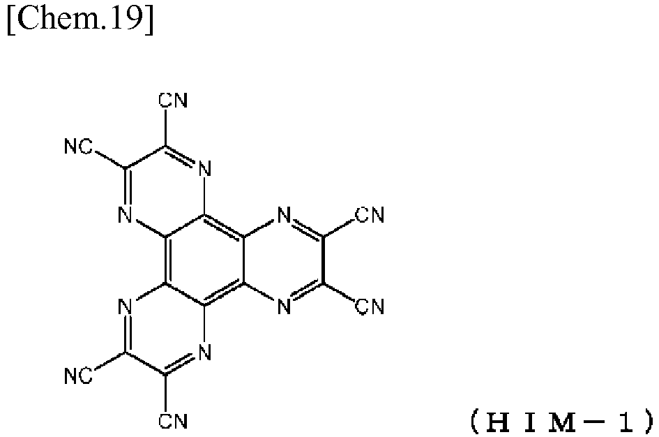
- On the
hole injection layer 3 was evaporation-deposited a triphenylamine derivative HTM-1 shown below to form a 60 nm thick firsthole transport layer 4.
- On the first
hole transport layer 4 was evaporation-deposited Compound 1-2 of Example 1 to form a 5 nm thick secondhole transport layer 5.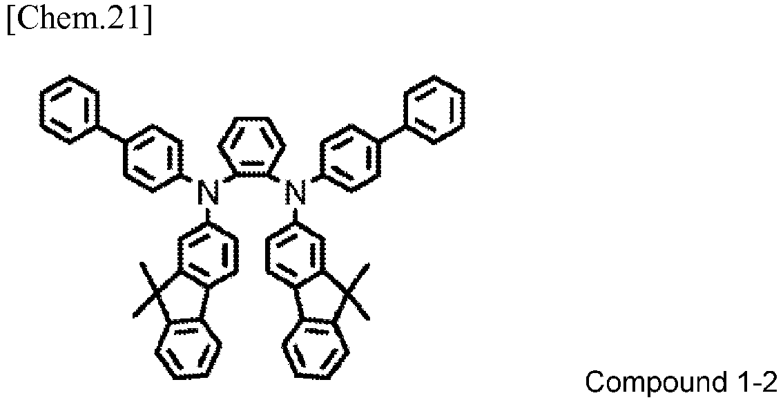
- On the second
hole transport layer 5 were co-deposited an iridium complex EMD-1 shown below and a carbazole derivative EMH-1 below at an EMD-1:ETH-1 deposition rate ratio of 5:95 to form a 20 nm thick emittinglayer 6.
- On the emitting
layer 6 were co-deposited a pyrimidine compound ETM-1 below and a compound ETM-2 below at an ETM-1:ETM-2 deposition rate ratio of 50:50 to form a 30 nm thickelectron transport layer 7.
- Lithium fluoride was evaporation-deposited on the
electron transport layer 7 to form a 1 nm thickelectron injection layer 8. - Finally, aluminum was deposited on the
electron injection layer 8 to form a 100 nmthick cathode 9. - An organic EL device was fabricated in the same manner as in Device Example 1, except that the second
hole transport layer 5 was formed using Compound 2-1 of Example 2 in place of Compound 1-2 of Example 1.
- An organic EL device was fabricated in the same manner as in Device Example 1, except that the second
hole transport layer 5 was formed using Compound 2-4 of Example 3 in place of Compound 1-2 of Example 1.
- For comparison, an organic EL device was fabricated in the same manner as in Device Example 1, except that the second
hole transport layer 5 was formed using HTM-2 shown below in place of Compound 1-2 of Example 1.
- For comparison, an organic EL device was fabricated in the same manner as in Device Example 2, except that the second
hole transport layer 5 was formed using HTM-3 shown below in place of Compound 2-1 of Example 2.
- For comparison, an organic EL device was fabricated in the same manner as in Device Example 2, except that the second
hole transport layer 5 was formed using HTM-4 shown below in place of Compound 2-1 of Example 2.
- For comparison, an organic EL device was fabricated in the same manner as in Device Example 2, except that the second
hole transport layer 5 was formed using HTM-5 shown below in place of Compound 2-1 of Example 2.
- The organic EL devices made in Device Examples 1 to 3 and Comparative Device Examples 1 to 4 were evaluated for characteristics in the atmosphere at ambient temperature. Emission characteristics of each device when a direct voltage was applied were determined. The results obtained are shown in Table 1 below.
- The life of the organic EL devices made in Device Examples 1 to 3 and Comparative Device Examples 1 to 4 was determined as follows. Each EL device was driven at a constant current that resulted in an initial luminance (the luminance at the onset of light emission) of 9000 cd/m2. The time required for the initial luminance to decay to 8550 cd/m2 (95% of the initial luminance) was recorded. The results are shown in Table 1.
Table 1 2nd Hole Transport Layer Voltage (V) (@10 mA/cm2) Luminance (cd/m2) (@10 mA/cm2) Emission Efficiency (cd/A) (@10 mA/cm2) Power Efficiency (lm/W) (@10 mA/cm2) Life (h) (95% decay) Device Example 1 Compound 1-2 4.12 7200 72.05 54.95 200 Device Example 2 Compound 2-1 4.30 7769 77.77 56.82 340 Device Example 3 Compound 2-4 4.12 7629 76.41 58.34 337 Comparative Device Example 1 HTM-2 4.20 6990 69.95 52.33 111 Comparative Device Example 2 HTM-3 4.28 7291 73.00 53.59 216 Comparative Device Example 3 HTM-4 4.20 7065 70.70 52.89 305 Comparative Device Example 4 HTM-5 4.45 7424 74.31 52.47 200 - Comparing the organic EL devices of Device Example 1 and Comparative Device Example 1, in which the aryldiamine compounds used to form the second
hole transport layer 5 were structurally similar except for the phenylene group linking the two amino groups, the emission efficiency of the device of Comparative Device Example 1 was 69.95 cd/A with a current density of 10 mA/cm2 applied, whilst that of the device of Device Example 1 was as high as 72.05 cd/A. - The power efficiency of the organic EL device of Comparative Device Example 1 was 52.33 lm/W, whereas that of the device of Device Example 1 was as high as 54.95 lm/W.
- The life (95% decay) of the organic EL device of Comparative Device Example 1 was 111 hours, whilst the device of Device Example 1 showed a remarkable extension of life to as long as 200 hours.
- Similarly, when comparing the organic EL devices of Device Example 2 and Comparative Device Examples 2 to 4, in which the aryldiamine compounds used to form the second
hole transport layer 5 were structurally similar except for the biphenylene group linking the two amino groups, the emission efficiency of the devices of Comparative Device Examples 2 to 4 was between 70.70 cd/A and 74.31 cd/A with a current density of 10 mA/cm2 applied, while that of the device of Device Example 2 was as high as 77.77 cd/A. - The power efficiency of the organic EL devices of Comparative Device Examples 2 to 4 was from 52.47 to 53.59 lm/W, whereas that of the device of Device Example 2 was as high as 56.82 lm/W.
- The life (95% decay) of the organic EL devices of Comparative Device Examples 2 to 4 was 200 to 305 hours, whereas the device of Device Example 2 showed an extension of life to as long as 340 hours.
- Similarly, on comparing the organic EL devices of Device Examples 2 and 3, in which the aryldiamine compounds used to form the second
hole transport layer 5 were structurally the same except for Ar2 and Ar3 in formula (1), it is seen that the organic EL device of Device Example 2, in which Ar2 and Ar3 in formula (1) were each an aromatic hydrocarbon group having a fused polycyclic structure, exhibited a higher emission efficiency and a longer life than that of Device Example 3, in which Ar2 and Ar3 in formula (1) were each an aromatic hydrocarbon group having no fused polycyclic structure. - The above results prove that the organic EL device using the aryldiamine compound of the invention achieves a higher emission efficiency and a longer life than conventional organic EL devices.
- The aryldiamine compound of the invention exhibits high hole transporting properties and high electron blocking properties and is stable in its thin film form and is therefore excellent as a material for fabricating organic EL devices. The organic EL device of the invention , which is fabricated by using the compound of the invention, exhibits high emission efficiency and high power efficiency, requires a low driving voltage, and shows excellent durability. Therefore, the organic EL device of the invention is promising for application to home appliances and lighting equipment.
-
- 1: Glass substrate
- 2: Transparent anode
- 3: Hole injection layer
- 4: First hole transport layer
- 5: Second hole transport layer
- 6: Emitting layer
- 7: Electron transport layer
- 8: Electron injection layer
- 9: Cathode
Claims (13)
- An aryldiamine compound represented by formula (1):
 wherein m and n each represent 0 or 1;Ar1, Ar2, Ar3, and Ar4 each represent an aromatic hydrocarbon group or an aromatic heterocyclic group;when m + n is 0 or 1, and Ar2 is an unsubstituted phenyl group, neither Ar3 nor Ar4 is an unsubstituted phenyl group; L1 and L2 each represent a single bond, a divalent aromatic hydrocarbon group, or a divalent aromatic heterocyclic group; andR1, R2, and R3 each represent a hydrogen atom, a deuterium atom, a fluorine atom, a chlorine atom, a cyano group, a nitro group, an alkyl group having 1 to 6 carbon atoms, a cycloalkyl group having 5 to 10 carbon atoms, an alkenyl group having 2 to 6 carbon atoms, an alkoxy group having 1 to 6 carbon atoms, a cycloalkoxy group having 5 to 10 carbon atoms, an aromatic hydrocarbon group, an aromatic heterocyclic group, or an aryloxy group.
 - The aryldiamine compound according to claim 1, wherein m and n in formula (1) are both zero, being represented by formula (1-1 a):
 wherein Ar5 and Ar8 each represent an aromatic hydrocarbon group or an aromatic heterocyclic group;Ar6 and Ar7 correspond to Ar2 and Ar3 in formula (1), respectively;when Ar6 is an unsubstituted phenyl group, Ar7 is not an unsubstituted phenyl group;R4 corresponds to R3 in formula (1);R5-8 represents multiple groups R5, R6, R7, and R8 bonded to the benzene ring at different positions;R9-12 represents multiple groups R9, R10, R11, and R12 bonded to the benzene ring at different positions; andR5, R6, R7, R8, R9, R10, R11, and R12 each represent a hydrogen atom, a deuterium atom, a fluorine atom, a chlorine atom, a cyano group, a nitro group, an alkyl group having 1 to 6 carbon atoms, a cycloalkyl group having 5 to 10 carbon atoms, an alkenyl group having 2 to 6 carbon atoms, an alkoxy group having 1 to 6 carbon atoms, a cycloalkoxy group having 5 to 10 carbon atoms, an aromatic hydrocarbon group, an aromatic heterocyclic group, or an aryloxy group.
 - The aryldiamine compound according to claim 1, wherein m and n in formula (1) are both zero, being represented by formula (1-1b):
 wherein Ar9 and Ar10 correspond to Ar2 and Ar3 in formula (1), respectively;when Ar9 is an unsubstituted phenyl group, Ar10 is not an unsubstituted phenyl group;R13 corresponds to R3 in formula (1);R14-18 represents multiple groups R14, R15, R16, R17, and R18 bonded to the benzene ring at different positions;R19-22 represents multiple groups R19, R20, R21, and R22 bonded to the benzene ring at different positions;R23-26 represents multiple groups R23, R24, R25, and R26 bonded to the benzene ring at different positions;R27-31 represents multiple groups R27, R28, R29, R30, and R31 bonded to the benzene ring at different positions; andR14, R15, R16, R17, R18, R19, R20, R21, R22, R23, R24, R25, R26, R27, R28, R29, R30, and R31 each represent a hydrogen atom, a deuterium atom, a fluorine atom, a chlorine atom, a cyano group, a nitro group, an alkyl group having 1 to 6 carbon atoms, a cycloalkyl group having 5 to 10 carbon atoms, an alkenyl group having 2 to 6 carbon atoms, an alkoxy group having 1 to 6 carbon atoms, a cycloalkoxy group having 5 to 10 carbon atoms, an aromatic hydrocarbon group, an aromatic heterocyclic group, or an aryloxy group.
 - The aryldiamine compound according to claim 1, wherein m is 1 and n is 0 in formula (1), being represented by formula (1-2a):
 wherein Ar11 and Ar14 each represent an aromatic hydrocarbon group or an aromatic heterocyclic group;Ar12 and Ar13 correspond to Ar2 and Ar3 in formula (1), respectively;when Ar12 is an unsubstituted phenyl group, Ar13 is not an unsubstituted phenyl group;R32 corresponds to R1 in formula (1);R33 corresponds to R3 in formula (1);R34-37 represents multiple groups R34, R35, R36, and R37 bonded to the benzene ring at different positions;R38-41 represents multiple groups R38, R39, R40, and R41 bonded to the benzene ring at different positions; andR34, R35, R36, R37, R38, R39, R40, and R41 each represent a hydrogen atom, a deuterium atom, a fluorine atom, a chlorine atom, a cyano group, a nitro group, an alkyl group having 1 to 6 carbon atoms, a cycloalkyl group having 5 to 10 carbon atoms, an alkenyl group having 2 to 6 carbon atoms, an alkoxy group having 1 to 6 carbon atoms, a cycloalkoxy group having 5 to 10 carbon atoms, an aromatic hydrocarbon group, an aromatic heterocyclic group, or an aryloxy group.
 - The aryldiamine compound according to claim 1, wherein m is 1 and n is 0 in formula (1), being represented by formula (1-2b):
 wherein Ar15 and Ar16 correspond to Ar2 and Ar3 in formula (1), respectively;when Ar15 is an unsubstituted phenyl group, Ar16 is not an unsubstituted phenyl group;R42 corresponds to R1 in formula (1);R43 corresponds to R3 in formula (1);R44-48 represents multiple groups R44, R45, R46, R47, and R48 bonded to the benzene ring at different positions;R49-52 represents multiple groups R49, R50, R51, and R52 bonded to the benzene ring at different positions;R53-56 represents multiple groups R53, R54, R55, and R56 bonded to the benzene ring at different positions;R57-61 represents multiple groups R57, R58, R59, R60, and R61 bonded to the benzene ring at different positions; andR44, R45, R46, R47, R48, R49, R50, R51, R52, R53, R54, R55, R56, R57, R58, R59, R60, and R61 each represent a hydrogen atom, a deuterium atom, a fluorine atom, a chlorine atom, a cyano group, a nitro group, an alkyl group having 1 to 6 carbon atoms, a cycloalkyl group having 5 to 10 carbon atoms, an alkenyl group having 2 to 6 carbon atoms, an alkoxy group having 1 to 6 carbon atoms, a cycloalkoxy group having 5 to 10 carbon atoms, an aromatic hydrocarbon group, an aromatic heterocyclic group, or an aryloxy group.
 - The aryldiamine compound according to claim 1, wherein m and n in formula (1) are both one, being represented by formula (1-3a):
 wherein Ar17 and Ar20 each represent an aromatic hydrocarbon group or an aromatic heterocyclic group;Ar18 and Ar19 correspond to Ar2 and Ar3 in formula (1), respectively;R62 and R63 correspond to R1 and R2 in formula (1), respectively;R64 corresponds to R3 in formula (1);R65-68 represents multiple groups R65, R66, R67, and R68 bonded to the benzene ring at different positions;R69-72 represent multiple groups R69, R70, R71, and R72 bonded to the benzene ring at different positions; andR65, R66, R67, R68, R69, R70, R71, and R72 each represent a hydrogen atom, a deuterium atom, a fluorine atom, a chlorine atom, a cyano group, a nitro group, an alkyl group having 1 to 6 carbon atoms, a cycloalkyl group having 5 to 10 carbon atoms, an alkenyl group having 2 to 6 carbon atoms, an alkoxy group having 1 to 6 carbon atoms, a cycloalkoxy group having 5 to 10 carbon atoms, an aromatic hydrocarbon group, an aromatic heterocyclic group, or an aryloxy group.
 - The aryldiamine compound according to claim 1, wherein m and n in formula (1) are both one, being represented by formula (1-3b):

 wherein Ar21 and Ar22 correspond to Ar2 and Ar3 in formula (1), respectively;R73 and R74 correspond to R1 and R2 in formula (1), respectively;R75 corresponds to R3 in formula (1);R76-80 represents multiple groups R76, R77, R78, R79, and R80 bonded to the benzene ring at different positions;R81-84 represents multiple groups R81, R82, R83, and R84 bonded to the benzene ring at different positions;R85-88 represents multiple groups R85, R86, R87, and R88 bonded to the benzene ring at different positions;R89-93 represents multiple groups R89, R90, R91, R92, and R93 bonded to the benzene ring at different positions; andR76, R77, R78, R79, R80, R81, R82, R83, R84, R85, R86, R87, R88, R89, R90, R91, R92, and R93 each represent a hydrogen atom, a deuterium atom, a fluorine atom, a chlorine atom, a cyano group, a nitro group, an alkyl group having 1 to 6 carbon atoms, a cycloalkyl group having 5 to 10 carbon atoms, an alkenyl group having 2 to 6 carbon atoms, an alkoxy group having 1 to 6 carbon atoms, a cycloalkoxy group having 5 to 10 carbon atoms, an aromatic hydrocarbon group, an aromatic heterocyclic group, or an aryloxy group.
 - An organic electroluminescent device comprising a pair of electrodes and at least one organic layer disposed between the pair of electrodes, wherein the aryldiamine compound according to claim 1 is used as comprising material of the at least one organic layer.
- The organic electroluminescent device according to claim 8, wherein the organic layer is a hole transporting layer.
- The organic electroluminescent device according to claim 8, wherein the organic layer is an electron blocking layer.
- The organic electroluminescent device according to claim 8, wherein the organic layer is a hole injection layer.
- The organic electroluminescent device according to claim 8, wherein the organic layer is an emission layer.
- The organic electroluminescent device according to claim 9, wherein the hole transporting layer is a dual layer composed of a first hole transport layer and a second hole transport layer.
Applications Claiming Priority (2)
| Application Number | Priority Date | Filing Date | Title |
|---|---|---|---|
| JP2016176349 | 2016-09-09 | ||
| PCT/JP2017/032239 WO2018047899A1 (en) | 2016-09-09 | 2017-09-07 | Aryldiamine compound and organic electroluminescent element |
Publications (3)
| Publication Number | Publication Date |
|---|---|
| EP3511316A1 true EP3511316A1 (en) | 2019-07-17 |
| EP3511316A4 EP3511316A4 (en) | 2020-03-18 |
| EP3511316B1 EP3511316B1 (en) | 2022-03-09 |
Family
ID=61561622
Family Applications (1)
| Application Number | Title | Priority Date | Filing Date |
|---|---|---|---|
| EP17848837.5A Not-in-force EP3511316B1 (en) | 2016-09-09 | 2017-09-07 | N2,n2,n2',n2'-tetrakis([1,1'-biphenyl]-4-yl)-[1,1'-biphenyl]-2,2'-diamine derivatives and related compounds for use in electroluminescent devices |
Country Status (7)
| Country | Link |
|---|---|
| US (1) | US11407709B2 (en) |
| EP (1) | EP3511316B1 (en) |
| JP (1) | JP7065029B2 (en) |
| KR (1) | KR102538722B1 (en) |
| CN (1) | CN109689616A (en) |
| TW (1) | TWI827533B (en) |
| WO (1) | WO2018047899A1 (en) |
Cited By (1)
| Publication number | Priority date | Publication date | Assignee | Title |
|---|---|---|---|---|
| WO2020094847A1 (en) | 2018-11-09 | 2020-05-14 | Dottikon Es Holding Ag | Di-, tri- and tetraphenylindane derivatives and their use in organic electronics |
Families Citing this family (1)
| Publication number | Priority date | Publication date | Assignee | Title |
|---|---|---|---|---|
| US12037332B2 (en) | 2018-03-23 | 2024-07-16 | Hodogaya Chemical Co., Ltd. | Compound including benzimidazole ring structure and organic electroluminescent element |
Family Cites Families (23)
| Publication number | Priority date | Publication date | Assignee | Title |
|---|---|---|---|---|
| US5494765A (en) * | 1993-01-14 | 1996-02-27 | Mita Industrial Co. Ltd | Electrophotosensitive material using a phenylenediamine derivative |
| JP3171755B2 (en) * | 1993-10-14 | 2001-06-04 | 京セラミタ株式会社 | Electrophotographic photoreceptor |
| JP3194657B2 (en) | 1993-11-01 | 2001-07-30 | 松下電器産業株式会社 | EL device |
| JP3828595B2 (en) | 1994-02-08 | 2006-10-04 | Tdk株式会社 | Organic EL device |
| JP3443476B2 (en) * | 1995-04-18 | 2003-09-02 | 京セラミタ株式会社 | Electrophotographic photoreceptor |
| US5780194A (en) * | 1995-04-18 | 1998-07-14 | Mita Industrial Co., Ltd. | Electrophotosensitive material |
| JP2001194657A (en) | 2000-01-11 | 2001-07-19 | Seiko Epson Corp | Liquid crystal display device, method of manufacturing the same, and electronic device |
| JP4770033B2 (en) | 2001-02-13 | 2011-09-07 | コニカミノルタホールディングス株式会社 | Organic electroluminescence device |
| JP2006156635A (en) * | 2004-11-29 | 2006-06-15 | Konica Minolta Holdings Inc | Organic electroluminescence element and display device |
| CN101282931A (en) | 2005-10-07 | 2008-10-08 | 东洋油墨制造株式会社 | Carbazole-containing amine compounds and uses thereof |
| JP2008133225A (en) * | 2006-11-29 | 2008-06-12 | Toyo Ink Mfg Co Ltd | Indole derivatives and uses thereof |
| JP2009170810A (en) * | 2008-01-18 | 2009-07-30 | Mitsui Chemicals Inc | Organic electroluminescence device |
| US9705092B2 (en) * | 2011-08-05 | 2017-07-11 | Universal Display Corporation | Phosphorescent organic light emitting devices combined with hole transport material having high operating stability |
| EP2722908A1 (en) | 2012-10-17 | 2014-04-23 | Novaled AG | Phosphorescent OLED and hole transporting materials for phosphorescent OLEDs |
| JP2016012676A (en) * | 2014-06-30 | 2016-01-21 | 三星ディスプレイ株式會社Samsung Display Co.,Ltd. | Material for organic electroluminescent devices, and organic electroluminescent device arranged by use thereof |
| TWI682920B (en) * | 2015-01-08 | 2020-01-21 | 日商保土谷化學工業股份有限公司 | Organic electroluminescent element |
| KR102285608B1 (en) * | 2015-03-23 | 2021-08-04 | 덕산네오룩스 주식회사 | Compound for organic electric element, organic electric element comprising the same and electronic device thereof |
| KR102357590B1 (en) | 2015-04-13 | 2022-02-03 | 덕산네오룩스 주식회사 | Compound for organic electric element, organic electric element comprising the same and electronic device thereof |
| KR102334857B1 (en) | 2015-09-08 | 2021-12-06 | 덕산네오룩스 주식회사 | Compound for organic electronic element, organic electronic element using the same, and an electronic device thereof |
| KR102572294B1 (en) | 2015-09-25 | 2023-08-30 | 덕산네오룩스 주식회사 | Compound for organic electronic element, organic electronic element using the same, and an electronic device thereof |
| JP2017165722A (en) * | 2016-03-09 | 2017-09-21 | 国立大学法人京都大学 | Asymmetric bis(1,2-diarylamino)benzene and method for producing the same |
| KR101686835B1 (en) * | 2016-06-28 | 2016-12-16 | 덕산네오룩스 주식회사 | Compound for organic electronic element, organic electronic element using the same, and an electronic device thereof |
| KR102710980B1 (en) | 2016-06-28 | 2024-09-27 | 덕산네오룩스 주식회사 | Compound for organic electronic element, organic electronic element using the same, and an electronic device thereof |
-
2017
- 2017-09-07 EP EP17848837.5A patent/EP3511316B1/en not_active Not-in-force
- 2017-09-07 KR KR1020197006410A patent/KR102538722B1/en active Active
- 2017-09-07 CN CN201780054983.9A patent/CN109689616A/en active Pending
- 2017-09-07 WO PCT/JP2017/032239 patent/WO2018047899A1/en not_active Ceased
- 2017-09-07 US US16/328,619 patent/US11407709B2/en active Active
- 2017-09-07 JP JP2018538463A patent/JP7065029B2/en active Active
- 2017-09-08 TW TW106130707A patent/TWI827533B/en active
Cited By (1)
| Publication number | Priority date | Publication date | Assignee | Title |
|---|---|---|---|---|
| WO2020094847A1 (en) | 2018-11-09 | 2020-05-14 | Dottikon Es Holding Ag | Di-, tri- and tetraphenylindane derivatives and their use in organic electronics |
Also Published As
| Publication number | Publication date |
|---|---|
| CN109689616A (en) | 2019-04-26 |
| EP3511316A4 (en) | 2020-03-18 |
| TWI827533B (en) | 2024-01-01 |
| JP7065029B2 (en) | 2022-05-11 |
| KR102538722B1 (en) | 2023-05-31 |
| EP3511316B1 (en) | 2022-03-09 |
| TW201811731A (en) | 2018-04-01 |
| KR20190051958A (en) | 2019-05-15 |
| US20200231534A1 (en) | 2020-07-23 |
| US11407709B2 (en) | 2022-08-09 |
| WO2018047899A1 (en) | 2018-03-15 |
| JPWO2018047899A1 (en) | 2019-08-15 |
Similar Documents
| Publication | Publication Date | Title |
|---|---|---|
| US10916711B2 (en) | Spiro compound having azafluorene ring structure, light-emitting material, and organic electroluminescent device | |
| EP3021372B1 (en) | Organic electroluminescent element | |
| EP2960958B1 (en) | Organic electroluminescence element | |
| EP3240057B1 (en) | Organic electroluminescent element | |
| KR102493763B1 (en) | Organic electroluminescent element | |
| EP2540707A1 (en) | Substituted pyridyl compound and organic electroluminescent element | |
| CN109651174B (en) | Organic electroluminescent compound, luminescent material and organic electroluminescent device | |
| JP6814156B2 (en) | Organic electroluminescence device | |
| EP3275969A1 (en) | Material for organic electroluminescence element, luminescent material, and organic electroluminescence element | |
| EP3416207B1 (en) | Organic electroluminescent element | |
| EP3343657A1 (en) | Organic electroluminescent element | |
| TWI741047B (en) | Organic electroluminescent device | |
| KR102931949B1 (en) | Arylamine compounds and electronic devices using the same | |
| EP4050083B1 (en) | Organic electroluminescent element | |
| US11407709B2 (en) | Aryldiamine compound and organic electroluminescent element | |
| CN114944459A (en) | Organic electroluminescent device | |
| CN113795481A (en) | Compound having benzotriazole ring structure and organic electroluminescent element | |
| EP4095124B1 (en) | Arylamine compound and organic electroluminescent element | |
| TW201429951A (en) | Compound with phenanthrene acridine ring structure and organic electroluminescent element | |
| KR20240151773A (en) | Arylamine compounds, organic electroluminescent devices, and electronic devices | |
| CN118284640A (en) | Triarylamine high molecular weight compound and organic electroluminescent element |
Legal Events
| Date | Code | Title | Description |
|---|---|---|---|
| STAA | Information on the status of an ep patent application or granted ep patent |
Free format text: STATUS: THE INTERNATIONAL PUBLICATION HAS BEEN MADE |
|
| PUAI | Public reference made under article 153(3) epc to a published international application that has entered the european phase |
Free format text: ORIGINAL CODE: 0009012 |
|
| STAA | Information on the status of an ep patent application or granted ep patent |
Free format text: STATUS: REQUEST FOR EXAMINATION WAS MADE |
|
| 17P | Request for examination filed |
Effective date: 20190305 |
|
| AK | Designated contracting states |
Kind code of ref document: A1 Designated state(s): AL AT BE BG CH CY CZ DE DK EE ES FI FR GB GR HR HU IE IS IT LI LT LU LV MC MK MT NL NO PL PT RO RS SE SI SK SM TR |
|
| AX | Request for extension of the european patent |
Extension state: BA ME |
|
| DAV | Request for validation of the european patent (deleted) | ||
| DAX | Request for extension of the european patent (deleted) | ||
| A4 | Supplementary search report drawn up and despatched |
Effective date: 20200213 |
|
| RIC1 | Information provided on ipc code assigned before grant |
Ipc: C09K 11/06 20060101ALI20200207BHEP Ipc: C07C 211/61 20060101ALI20200207BHEP Ipc: C07C 211/54 20060101AFI20200207BHEP Ipc: H01L 51/50 20060101ALI20200207BHEP |
|
| STAA | Information on the status of an ep patent application or granted ep patent |
Free format text: STATUS: EXAMINATION IS IN PROGRESS |
|
| 17Q | First examination report despatched |
Effective date: 20210114 |
|
| GRAP | Despatch of communication of intention to grant a patent |
Free format text: ORIGINAL CODE: EPIDOSNIGR1 |
|
| STAA | Information on the status of an ep patent application or granted ep patent |
Free format text: STATUS: GRANT OF PATENT IS INTENDED |
|
| INTG | Intention to grant announced |
Effective date: 20211028 |
|
| GRAS | Grant fee paid |
Free format text: ORIGINAL CODE: EPIDOSNIGR3 |
|
| GRAA | (expected) grant |
Free format text: ORIGINAL CODE: 0009210 |
|
| STAA | Information on the status of an ep patent application or granted ep patent |
Free format text: STATUS: THE PATENT HAS BEEN GRANTED |
|
| AK | Designated contracting states |
Kind code of ref document: B1 Designated state(s): AL AT BE BG CH CY CZ DE DK EE ES FI FR GB GR HR HU IE IS IT LI LT LU LV MC MK MT NL NO PL PT RO RS SE SI SK SM TR |
|
| REG | Reference to a national code |
Ref country code: CH Ref legal event code: EP Ref country code: AT Ref legal event code: REF Ref document number: 1474052 Country of ref document: AT Kind code of ref document: T Effective date: 20220315 |
|
| REG | Reference to a national code |
Ref country code: IE Ref legal event code: FG4D |
|
| REG | Reference to a national code |
Ref country code: DE Ref legal event code: R096 Ref document number: 602017054479 Country of ref document: DE |
|
| REG | Reference to a national code |
Ref country code: LT Ref legal event code: MG9D |
|
| REG | Reference to a national code |
Ref country code: NL Ref legal event code: MP Effective date: 20220309 |
|
| PG25 | Lapsed in a contracting state [announced via postgrant information from national office to epo] |
Ref country code: SE Free format text: LAPSE BECAUSE OF FAILURE TO SUBMIT A TRANSLATION OF THE DESCRIPTION OR TO PAY THE FEE WITHIN THE PRESCRIBED TIME-LIMIT Effective date: 20220309 Ref country code: RS Free format text: LAPSE BECAUSE OF FAILURE TO SUBMIT A TRANSLATION OF THE DESCRIPTION OR TO PAY THE FEE WITHIN THE PRESCRIBED TIME-LIMIT Effective date: 20220309 Ref country code: NO Free format text: LAPSE BECAUSE OF FAILURE TO SUBMIT A TRANSLATION OF THE DESCRIPTION OR TO PAY THE FEE WITHIN THE PRESCRIBED TIME-LIMIT Effective date: 20220609 Ref country code: LT Free format text: LAPSE BECAUSE OF FAILURE TO SUBMIT A TRANSLATION OF THE DESCRIPTION OR TO PAY THE FEE WITHIN THE PRESCRIBED TIME-LIMIT Effective date: 20220309 Ref country code: HR Free format text: LAPSE BECAUSE OF FAILURE TO SUBMIT A TRANSLATION OF THE DESCRIPTION OR TO PAY THE FEE WITHIN THE PRESCRIBED TIME-LIMIT Effective date: 20220309 Ref country code: BG Free format text: LAPSE BECAUSE OF FAILURE TO SUBMIT A TRANSLATION OF THE DESCRIPTION OR TO PAY THE FEE WITHIN THE PRESCRIBED TIME-LIMIT Effective date: 20220609 |
|
| REG | Reference to a national code |
Ref country code: AT Ref legal event code: MK05 Ref document number: 1474052 Country of ref document: AT Kind code of ref document: T Effective date: 20220309 |
|
| PG25 | Lapsed in a contracting state [announced via postgrant information from national office to epo] |
Ref country code: LV Free format text: LAPSE BECAUSE OF FAILURE TO SUBMIT A TRANSLATION OF THE DESCRIPTION OR TO PAY THE FEE WITHIN THE PRESCRIBED TIME-LIMIT Effective date: 20220309 Ref country code: GR Free format text: LAPSE BECAUSE OF FAILURE TO SUBMIT A TRANSLATION OF THE DESCRIPTION OR TO PAY THE FEE WITHIN THE PRESCRIBED TIME-LIMIT Effective date: 20220610 Ref country code: FI Free format text: LAPSE BECAUSE OF FAILURE TO SUBMIT A TRANSLATION OF THE DESCRIPTION OR TO PAY THE FEE WITHIN THE PRESCRIBED TIME-LIMIT Effective date: 20220309 |
|
| PG25 | Lapsed in a contracting state [announced via postgrant information from national office to epo] |
Ref country code: NL Free format text: LAPSE BECAUSE OF FAILURE TO SUBMIT A TRANSLATION OF THE DESCRIPTION OR TO PAY THE FEE WITHIN THE PRESCRIBED TIME-LIMIT Effective date: 20220309 |
|
| PG25 | Lapsed in a contracting state [announced via postgrant information from national office to epo] |
Ref country code: SM Free format text: LAPSE BECAUSE OF FAILURE TO SUBMIT A TRANSLATION OF THE DESCRIPTION OR TO PAY THE FEE WITHIN THE PRESCRIBED TIME-LIMIT Effective date: 20220309 Ref country code: SK Free format text: LAPSE BECAUSE OF FAILURE TO SUBMIT A TRANSLATION OF THE DESCRIPTION OR TO PAY THE FEE WITHIN THE PRESCRIBED TIME-LIMIT Effective date: 20220309 Ref country code: RO Free format text: LAPSE BECAUSE OF FAILURE TO SUBMIT A TRANSLATION OF THE DESCRIPTION OR TO PAY THE FEE WITHIN THE PRESCRIBED TIME-LIMIT Effective date: 20220309 Ref country code: PT Free format text: LAPSE BECAUSE OF FAILURE TO SUBMIT A TRANSLATION OF THE DESCRIPTION OR TO PAY THE FEE WITHIN THE PRESCRIBED TIME-LIMIT Effective date: 20220711 Ref country code: ES Free format text: LAPSE BECAUSE OF FAILURE TO SUBMIT A TRANSLATION OF THE DESCRIPTION OR TO PAY THE FEE WITHIN THE PRESCRIBED TIME-LIMIT Effective date: 20220309 Ref country code: EE Free format text: LAPSE BECAUSE OF FAILURE TO SUBMIT A TRANSLATION OF THE DESCRIPTION OR TO PAY THE FEE WITHIN THE PRESCRIBED TIME-LIMIT Effective date: 20220309 Ref country code: CZ Free format text: LAPSE BECAUSE OF FAILURE TO SUBMIT A TRANSLATION OF THE DESCRIPTION OR TO PAY THE FEE WITHIN THE PRESCRIBED TIME-LIMIT Effective date: 20220309 Ref country code: AT Free format text: LAPSE BECAUSE OF FAILURE TO SUBMIT A TRANSLATION OF THE DESCRIPTION OR TO PAY THE FEE WITHIN THE PRESCRIBED TIME-LIMIT Effective date: 20220309 |
|
| PGFP | Annual fee paid to national office [announced via postgrant information from national office to epo] |
Ref country code: DE Payment date: 20220908 Year of fee payment: 6 |
|
| PG25 | Lapsed in a contracting state [announced via postgrant information from national office to epo] |
Ref country code: PL Free format text: LAPSE BECAUSE OF FAILURE TO SUBMIT A TRANSLATION OF THE DESCRIPTION OR TO PAY THE FEE WITHIN THE PRESCRIBED TIME-LIMIT Effective date: 20220309 Ref country code: IS Free format text: LAPSE BECAUSE OF FAILURE TO SUBMIT A TRANSLATION OF THE DESCRIPTION OR TO PAY THE FEE WITHIN THE PRESCRIBED TIME-LIMIT Effective date: 20220709 Ref country code: AL Free format text: LAPSE BECAUSE OF FAILURE TO SUBMIT A TRANSLATION OF THE DESCRIPTION OR TO PAY THE FEE WITHIN THE PRESCRIBED TIME-LIMIT Effective date: 20220309 |
|
| REG | Reference to a national code |
Ref country code: DE Ref legal event code: R097 Ref document number: 602017054479 Country of ref document: DE |
|
| PLBE | No opposition filed within time limit |
Free format text: ORIGINAL CODE: 0009261 |
|
| STAA | Information on the status of an ep patent application or granted ep patent |
Free format text: STATUS: NO OPPOSITION FILED WITHIN TIME LIMIT |
|
| PG25 | Lapsed in a contracting state [announced via postgrant information from national office to epo] |
Ref country code: DK Free format text: LAPSE BECAUSE OF FAILURE TO SUBMIT A TRANSLATION OF THE DESCRIPTION OR TO PAY THE FEE WITHIN THE PRESCRIBED TIME-LIMIT Effective date: 20220309 |
|
| 26N | No opposition filed |
Effective date: 20221212 |
|
| PG25 | Lapsed in a contracting state [announced via postgrant information from national office to epo] |
Ref country code: SI Free format text: LAPSE BECAUSE OF FAILURE TO SUBMIT A TRANSLATION OF THE DESCRIPTION OR TO PAY THE FEE WITHIN THE PRESCRIBED TIME-LIMIT Effective date: 20220309 |
|
| PG25 | Lapsed in a contracting state [announced via postgrant information from national office to epo] |
Ref country code: MC Free format text: LAPSE BECAUSE OF FAILURE TO SUBMIT A TRANSLATION OF THE DESCRIPTION OR TO PAY THE FEE WITHIN THE PRESCRIBED TIME-LIMIT Effective date: 20220309 |
|
| REG | Reference to a national code |
Ref country code: CH Ref legal event code: PL |
|
| GBPC | Gb: european patent ceased through non-payment of renewal fee |
Effective date: 20220907 |
|
| REG | Reference to a national code |
Ref country code: BE Ref legal event code: MM Effective date: 20220930 |
|
| PG25 | Lapsed in a contracting state [announced via postgrant information from national office to epo] |
Ref country code: LU Free format text: LAPSE BECAUSE OF NON-PAYMENT OF DUE FEES Effective date: 20220907 |
|
| PG25 | Lapsed in a contracting state [announced via postgrant information from national office to epo] |
Ref country code: LI Free format text: LAPSE BECAUSE OF NON-PAYMENT OF DUE FEES Effective date: 20220930 Ref country code: IT Free format text: LAPSE BECAUSE OF FAILURE TO SUBMIT A TRANSLATION OF THE DESCRIPTION OR TO PAY THE FEE WITHIN THE PRESCRIBED TIME-LIMIT Effective date: 20220309 Ref country code: IE Free format text: LAPSE BECAUSE OF NON-PAYMENT OF DUE FEES Effective date: 20220907 Ref country code: FR Free format text: LAPSE BECAUSE OF NON-PAYMENT OF DUE FEES Effective date: 20220930 Ref country code: CH Free format text: LAPSE BECAUSE OF NON-PAYMENT OF DUE FEES Effective date: 20220930 |
|
| PG25 | Lapsed in a contracting state [announced via postgrant information from national office to epo] |
Ref country code: BE Free format text: LAPSE BECAUSE OF NON-PAYMENT OF DUE FEES Effective date: 20220930 |
|
| PG25 | Lapsed in a contracting state [announced via postgrant information from national office to epo] |
Ref country code: GB Free format text: LAPSE BECAUSE OF NON-PAYMENT OF DUE FEES Effective date: 20220907 |
|
| PG25 | Lapsed in a contracting state [announced via postgrant information from national office to epo] |
Ref country code: HU Free format text: LAPSE BECAUSE OF FAILURE TO SUBMIT A TRANSLATION OF THE DESCRIPTION OR TO PAY THE FEE WITHIN THE PRESCRIBED TIME-LIMIT; INVALID AB INITIO Effective date: 20170907 |
|
| REG | Reference to a national code |
Ref country code: DE Ref legal event code: R119 Ref document number: 602017054479 Country of ref document: DE |
|
| PG25 | Lapsed in a contracting state [announced via postgrant information from national office to epo] |
Ref country code: CY Free format text: LAPSE BECAUSE OF FAILURE TO SUBMIT A TRANSLATION OF THE DESCRIPTION OR TO PAY THE FEE WITHIN THE PRESCRIBED TIME-LIMIT Effective date: 20220309 |
|
| PG25 | Lapsed in a contracting state [announced via postgrant information from national office to epo] |
Ref country code: MK Free format text: LAPSE BECAUSE OF FAILURE TO SUBMIT A TRANSLATION OF THE DESCRIPTION OR TO PAY THE FEE WITHIN THE PRESCRIBED TIME-LIMIT Effective date: 20220309 |
|
| PG25 | Lapsed in a contracting state [announced via postgrant information from national office to epo] |
Ref country code: DE Free format text: LAPSE BECAUSE OF NON-PAYMENT OF DUE FEES Effective date: 20240403 |
|
| PG25 | Lapsed in a contracting state [announced via postgrant information from national office to epo] |
Ref country code: MT Free format text: LAPSE BECAUSE OF FAILURE TO SUBMIT A TRANSLATION OF THE DESCRIPTION OR TO PAY THE FEE WITHIN THE PRESCRIBED TIME-LIMIT Effective date: 20220309 |
|
| PG25 | Lapsed in a contracting state [announced via postgrant information from national office to epo] |
Ref country code: TR Free format text: LAPSE BECAUSE OF FAILURE TO SUBMIT A TRANSLATION OF THE DESCRIPTION OR TO PAY THE FEE WITHIN THE PRESCRIBED TIME-LIMIT Effective date: 20220309 |