EP3511250B1 - Movable tunnel braking system and passenger boarding bridge - Google Patents
Movable tunnel braking system and passenger boarding bridge Download PDFInfo
- Publication number
- EP3511250B1 EP3511250B1 EP17847931.7A EP17847931A EP3511250B1 EP 3511250 B1 EP3511250 B1 EP 3511250B1 EP 17847931 A EP17847931 A EP 17847931A EP 3511250 B1 EP3511250 B1 EP 3511250B1
- Authority
- EP
- European Patent Office
- Prior art keywords
- tunnel
- brake
- hinged
- wire rope
- braking system
- Prior art date
- Legal status (The legal status is an assumption and is not a legal conclusion. Google has not performed a legal analysis and makes no representation as to the accuracy of the status listed.)
- Active
Links
Images



Classifications
-
- F—MECHANICAL ENGINEERING; LIGHTING; HEATING; WEAPONS; BLASTING
- F16—ENGINEERING ELEMENTS AND UNITS; GENERAL MEASURES FOR PRODUCING AND MAINTAINING EFFECTIVE FUNCTIONING OF MACHINES OR INSTALLATIONS; THERMAL INSULATION IN GENERAL
- F16D—COUPLINGS FOR TRANSMITTING ROTATION; CLUTCHES; BRAKES
- F16D63/00—Brakes not otherwise provided for; Brakes combining more than one of the types of groups F16D49/00 - F16D61/00
- F16D63/006—Positive locking brakes
-
- B—PERFORMING OPERATIONS; TRANSPORTING
- B64—AIRCRAFT; AVIATION; COSMONAUTICS
- B64F—GROUND OR AIRCRAFT-CARRIER-DECK INSTALLATIONS SPECIALLY ADAPTED FOR USE IN CONNECTION WITH AIRCRAFT; DESIGNING, MANUFACTURING, ASSEMBLING, CLEANING, MAINTAINING OR REPAIRING AIRCRAFT, NOT OTHERWISE PROVIDED FOR; HANDLING, TRANSPORTING, TESTING OR INSPECTING AIRCRAFT COMPONENTS, NOT OTHERWISE PROVIDED FOR
- B64F1/00—Ground or aircraft-carrier-deck installations
- B64F1/30—Ground or aircraft-carrier-deck installations for embarking or disembarking passengers
- B64F1/305—Bridges extending between terminal building and aircraft, e.g. telescopic, vertically adjustable
-
- B—PERFORMING OPERATIONS; TRANSPORTING
- B64—AIRCRAFT; AVIATION; COSMONAUTICS
- B64F—GROUND OR AIRCRAFT-CARRIER-DECK INSTALLATIONS SPECIALLY ADAPTED FOR USE IN CONNECTION WITH AIRCRAFT; DESIGNING, MANUFACTURING, ASSEMBLING, CLEANING, MAINTAINING OR REPAIRING AIRCRAFT, NOT OTHERWISE PROVIDED FOR; HANDLING, TRANSPORTING, TESTING OR INSPECTING AIRCRAFT COMPONENTS, NOT OTHERWISE PROVIDED FOR
- B64F1/00—Ground or aircraft-carrier-deck installations
- B64F1/30—Ground or aircraft-carrier-deck installations for embarking or disembarking passengers
- B64F1/305—Bridges extending between terminal building and aircraft, e.g. telescopic, vertically adjustable
- B64F1/3055—Bridges extending between terminal building and aircraft, e.g. telescopic, vertically adjustable with hinged head interface between aircraft and passenger bridge
-
- E—FIXED CONSTRUCTIONS
- E01—CONSTRUCTION OF ROADS, RAILWAYS, OR BRIDGES
- E01D—CONSTRUCTION OF BRIDGES, ELEVATED ROADWAYS OR VIADUCTS; ASSEMBLY OF BRIDGES
- E01D15/00—Movable or portable bridges; Floating bridges
- E01D15/12—Portable or sectional bridges
- E01D15/124—Folding or telescopic bridges; Bridges built up from folding or telescopic sections
-
- F—MECHANICAL ENGINEERING; LIGHTING; HEATING; WEAPONS; BLASTING
- F16—ENGINEERING ELEMENTS AND UNITS; GENERAL MEASURES FOR PRODUCING AND MAINTAINING EFFECTIVE FUNCTIONING OF MACHINES OR INSTALLATIONS; THERMAL INSULATION IN GENERAL
- F16D—COUPLINGS FOR TRANSMITTING ROTATION; CLUTCHES; BRAKES
- F16D63/00—Brakes not otherwise provided for; Brakes combining more than one of the types of groups F16D49/00 - F16D61/00
- F16D63/008—Brakes acting on a linearly moving member
Definitions
- the present disclosure relates to a movable tunnel braking system, and also relates to a passenger boarding bridge having the movable tunnel braking system.
- Fig. 1 is a schematic view of a passenger boarding bridge
- Fig. 2 is a principle schematic view of an existing passenger boarding bridge
- the existing passenger boarding bridge generally includes three tunnels that are sleeve-connected with one another in turn.
- the three tunnels are a tunnel A 21, a tunnel B 22, and a tunnel C 23, respectively.
- the tunnel A 21 is hinged to the rotunda 1.
- the rotunda 1 is fixed on the ground by a column under the rotunda 1.
- the tunnel C 23 is connected to a lifting column 3.
- the lifting column 3 is connected to a horizontal drive unit 4.
- the horizontal drive unit 4 drives the tunnel C forward or backward.
- the tunnel B 22 is sleeved between the tunnel A 21 and the tunnel C 23.
- a first movable pulley 221 and a second movable pulley 222 are fixed on the bottom of the tunnel B 22.
- the retracting wire rope 51 has one end fixed to a tailing end of the tunnel A 21, the other end fixed to a tailing end of the tunnel C 23, and a center portion passing through the second movable pulley 222.
- the tunnel A 21, the tunnel B 22, the tunnel C 23, the retracting wire rope 51 and the second movable pulley 222 form one set of movable pulley mechanism.
- the tensile wire rope 52 has one end fixed to a leading end of the tunnel A 21, the other end fixed to a tailing end of the tunnel C 23, and the center portion passing through the first movable pulley 221.
- the tunnel A 21, the tunnel B 22, the tunnel C 23, the tensile wire rope 52 and the first movable pulley 221 form the other set of movable pulley mechanism.
- the three tunnels realize synchronous movement through the two sets of movable pulley mechanisms.
- the passenger boarding bridge may be used in the airport for passengers to board on the airplane. After the tunnel C 23 docks with a cabin door, the passenger can enter the passenger boarding bridge through the turntable 1, then pass through the tunnel A 21, the tunnel B 22 and the tunnel C 23 in turn, and finally enter the airplane.
- the passenger boarding bridge may also be installed on ferry ports for passengers to board on a ship.
- the passenger boarding bridge may also be called a boarding bridge or other names.
- the retracting wire rope 51 and the tensile wire rope 52 may be broken, and the passenger boarding bridge is not in a horizontal state under many circumstances, if the retracting wire rope 51 or the tensile wire rope 52 is broken, the tunnel B 22 will move uncontrolledly which results safety hazards. It is necessary to be able to brake the tunnel B 22 under the circumstance that the wire rope is broken, in order to ensure the safety of personnel in the tunnel.
- the existing tunnel braking system has a complicated structure and low reliability.
- CN201777388U discloses a three-channel boarding bridge with a detection braking device.
- An object of the present disclosure is to overcome the above-mentioned shortcomings of the prior art. It is provided with a movable tunnel braking system that may brake two tunnels adjacent to each other when the tensile wire rope or the retracting wire rope is broken.
- the movable passage braking system has a simple structure and high reliability..
- Another object of the present disclosure is to provide a passenger boarding bridge having the movable tunnel braking system.
- a movable tunnel braking system for a passenger boarding bridge is provided, in accordance with appended claim 1.
- a passenger boarding bridge including the movable tunnel braking system according to any of appended claims 1-10.
- the passenger boarding bridge has three tunnels.
- the movable tunnel braking system of the present disclosure brakes two adjacent tunnels of the passenger boarding bridge by a brake plate, a brake pin and a triggering device.
- the movable tunnel braking system has a simple and compact structure and is installed conveniently.
- the movable tunnel braking system of the present disclosure may be realized completely by means of the mechanical structure, due to extremely high action reliability, can brake the movable tunnel effectively when the tensile wire rope or the retracting wire rope is broken, thereby ensuring the safety of passengers.
- an embodiment of the present disclosure discloses a movable tunnel braking system.
- the movable tunnel braking system is used for a passenger boarding bridge shown in Fig. 1 and Fig. 2 , wherein the passenger boarding bridge includes a plurality of tunnels that are sequentially sleeve-connected with one another, and a tensile wire rope 52 and a retracting wire rope 51 that are connected to the plurality of tunnels.
- the movable tunnel braking system includes a brake plate 223, a brake pin 67, and a triggering device, wherein the brake plate 223 is fixedly disposed at a first tunnel, and the brake pin 67 is movably disposed at a second tunnel that is sleeve-connected with the first tunnel.
- the first tunnel is a tunnel B 22, and the second tunnel is a tunnel C 23.
- the "first tunnel” and the "second tunnel” in this embodiment are merely used to indicate one of two tunnels that are adjacent and sleeve-connected with each other, but not limit the tunnel.
- the first tunnel may also represent the tunnel C 23 and the second tunnel is the tunnel B 22.
- the number of tunnels of the passenger boarding bridge is not limited to two, but may also be three or more.
- the brake plate 223 is substantially an elongated strip-shaped steel sheet, on which a plurality of brake slots 224 are disposed.
- the structure of the brake slot 224 is substantially a waist-shaped hole.
- the structure of the brake slot 224 is merely exemplary, but not limit to the specific structure.
- the brake slot 224 may also be a circular slot, a square slot, a trapezoidal slot or a V-shaped slot and the other shapes.
- the brake pin 67 may be used to combine with the brake slot 224 at the brake plate 223. That is to say, the brake pin 67 may be protruded into the brake slot 224 to combine with the brake slot 224 together, in this way, the relative movement between the first tunnel and the second tunnel may be restricted, so as to ensure the safety of people in the tunnel.
- the brake pin 67 may be triggered by a triggering device to perform the corresponding action of combining with the brake slot 224. It should be understood by the person skilled in the art that for the present disclosure, the specific action modes of the brake pin 67 are not limited.
- the brake pin 67 may be slidably disposed at the second tunnel, and may slide into the brake slot 224.
- the brake pin 67 is hinged to the second tunnel, by rotating the brake pin 67, a distal end of the brake pin 67 may enter into the brake slot 224.
- the triggering device includes a mechanical blocking portion, a linkage mechanism, and a tensile spring.
- the mechanical blocking portion is fixedly disposed at the second tunnel.
- the linkage mechanism is movably disposed at the second tunnel, and connected to one end of the tensile wire rope 52 or the retracting wire rope 51.
- the linkage mechanism abuts against the mechanical blocking portion under the action of a tensile force of the tensile wire rope 52 or the retracting wire rope 51.
- the two ends of the tensile spring are respectively connected to the linkage mechanism and the second tunnel, so that when the tensile wire rope 52 or the retracting wire rope 51 is broken, the linkage mechanism is driven to move and drives the brake pin 67 to combine with the brake slot 224, to brake the first tunnel and the second tunnel.
- the triggering device will be described in detail.
- the number of the brake pin 67 and the triggering device may be adjusted as needed.
- the brake pin 67 and the triggering device each may be configured in two, and the linkage mechanisms of the two triggering devices are respectively connected to the tensile wire rope 52 and the retracting wire rope 51.
- the linkage mechanism of each of the triggering devices is connected to one of the brake pins 67.
- the number of the brake pin 67 and the triggering device may be only one, so that the linkage mechanism of the triggering device is connected to the tensile wire rope 52 or the retracting wire rope 51.
- One set of movable tunnel braking system may detect breakage of the tensile wire rope 52 or the retracting wire rope 51.
- Two sets of the movable tunnel braking systems may be provided to detect the state of the tensile wire rope 52 and the retracting wire rope 51.
- the number of the triggering devices is two.
- the linkage mechanisms of the two triggering devices are respectively connected to one end of the tensile wire rope 52 and the retracting wire rope 51. And the two linkage mechanisms are also connected to the same brake pin 67.
- the tensile wire rope 52 and the retracting wire rope 51 may be detected, and may be broken by the action of one brake pin 67, to improve reliability of the action while reducing the number of the parts.
- one second hinged seat 234 is disposed at the second tunnel, and the brake pin 67 is hinged on the second hinged seat 234.
- a positioning spring 73 for providing a tension for the brake pin 67 is provided at the second tunnel, wherein a positioning stop plate 9 is provided on the second hinged seat 234, a striking rod 671 is provided at the brake pin 67, and the two ends of the positioning spring 73 are respectively connected to the striking rod 671 and the positioning stop plate 9.
- the positioning spring 73 may disengage the brake pin 67 from the brake slot 224, that is, under the action of the tension of the positioning spring 73, the striking rod 671 is in contact with the positioning stop plate 9, so that the brake pin 67 may be positioned at a place that is disengaged away from the brake slot 224. In this place, the brake pin 67 does not affect the movement between the first tunnel and the second tunnel. Only when the tensile wire rope 52 or the retracting wire rope 51 is broken, the brake pin 67 will be driven by the triggering device to overcome the function of a tension force of the positioning spring 73 to combine with the brake slot 224.
- the linkage mechanism presents two structures, wherein the linkage mechanism with a first structure is presented as follows: the linkage mechanism includes a first hinged seat 232, a first hinged rod 61, a second hinged rod 62, a third hinged rod 63, and a fourth hinged rod 64.
- the first hinged seat 232 is fixedly disposed at the second tunnel.
- the first hinged rod 61 has one end connected to the tensile wire rope 52 or the retracting wire rope 51, and the other end hinged to the second hinged rod 62.
- the second hinged rod 62 has one end hinged to the first hinged seat 232 and the other end used to hinge to the first hinged rod 61 and abut against a mechanical blocking portion 231.
- the third hinged rod 63 has one end hinged to the first hinged seat 232. Both ends of the fourth hinged rod 64 are hinged to the third hinged rod 63 and the brake pin 67, respectively.
- the second hinged rod 62 is connected to one end of a tensile spring 71. The other end of the tensile spring 71 is connected to the second tunnel.
- the third hinged rod 63 may be driven to rotate to drive the fourth hinged rod 64 to move, and finally the fourth hinged rod 64 drives the brake pin 67 to combine with the brake slot 224.
- the second hinged rod 62 rotates at a certain angle a of 5° ⁇ a ⁇ 30° , that is to say, when the second hinged rod 62 rotates within a certain angle a, the third hinged rod 63 is not rotated, and thereby avoiding false operation.
- the linkage mechanism with the first structure is used to connect the retracting wire rope 51, but it should be noted that the linkage mechanism with the first structure may also be used to connect the tensile wire rope 52.
- the linkage mechanism includes a main hinged rod 66, an intermediate hinged shaft 663, and a connecting bolt 65.
- the main hinged rod 66 has one end that is coaxially hinged with the brake pin 67, and the other end that is in contact with a mechanical blocking portion 233.
- the main hinged rod 66 is also connected to a tensile spring 72 disposed at the second tunnel.
- the intermediate hinged shaft 663 is hinged to the main hinged rod 66.
- the connecting bolt 65 has one end that is connected to the tensile wire rope 52 or the retracting wire rope 51, and the other end that is connected to the intermediate hinged shaft 663.
- the main hinged rod 66 includes a body 664 and a connecting handle 661 disposed at one end of the body 664.
- the connecting handle 661 is coaxially hinged with the brake pin 67.
- the body is rotated by a certain angle b to contact with the brake pin 67 so as to drive the brake pin 67 to combine with the brake slot 224.
- a fixing cover 662 is also fixedly connected to the body.
- the intermediate hinged shaft 663 is hinged between the fixing cover 662 and the body.
- the main hinged rod 66 is rotated by a certain angle b of 5° ⁇ b ⁇ 30° , that is to say, when the main hinged rod 66 rotates within a certain angle b , the brake pin 67 is not rotated, and thereby avoiding false operation.
- the main hinged rod 66 of the second linkage mechanism is connected to the tensile wire rope 52, however, it should be noted that the second linkage mechanism may also be used on the retracting wire rope 51.
- the linkage mechanisms with the two structures as above mentioned may be used independently or together.
- the first linkage mechanism and the second linkage mechanism are simultaneously used.
- the retracting wire rope 51 when the tensile wire rope 52 is in a tensioned state, the retracting wire rope 51 may be in a certain relaxed state under some working conditions, but the retracting wire rope 51 is not broken, and thereby does not need to brake.
- the tensile spring 71 may rotate the second hinged rod 62, the rotational angle of the second hinged rod 62 does not exceed the range of the angle a, so that the second hinged rod 62 may not rotate the third hinged rod 63, and thereby avoiding accidental combination between the brake pin 67 and the brake slot 224 on the brake plate 223 to ensures security.
- the tensile spring 71 drives the second hinged rod 62 to rotate beyond the range of the angle a, so that the second hinged rod 62 may drive the third hinged rod 63 to start rotating, and finally the brake pin 67 is combined together with the brake slot 224 at the brake plate 223 to brake the first tunnel and the second tunnel.
- the tensile wire rope 52 when the retracting wire rope 51 is in a tensioned state, the tensile wire rope 52 may be in a certain relaxed state under some operating conditions, but the tensile wire rope 52 is not broken and thus does not need to brake.
- the tensile spring 72 may rotate the main hinged rod 66, the rotational angle of the main hinged rod 66 does not exceed the range of the angle b. Thereby, the main hinged rod 66 may not rotate the brake pin 67, to avoid the accident combination of the brake pin 67 and the brake slot 224, so as to ensure security.
- the tensile spring 72 drives the main hinged rod 66 to rotate beyond the range of the angle b, so that the main hinged rod 66 may start rotating the brake pin 67, and finally the brake pin 67 and the brake slot 224 on the brake plate 223 are combined with each other, to brake the first tunnel and the second tunnel.
- a travel switch 8 may also be disposed at the second tunnel.
- the travel switch is used to detect whether the brake pin 67 is combined with the brake slot 224 or not.
- the brake pin 67 may just trigger the travel switch 8.
- the travel switch 8 is triggered to generate a detection signal which can be transmitted to a control system of the passenger boarding bridge. After receiving the detection signal, the control system may stop movement of a lifting column and a horizontal drive unit.
- a braking process may be completely realized by means of a mechanical structure, without using any electrical component, to avoid unreliability of the electrical components.
- the electrical components only play an auxiliary function of transmitting detection signals to the control system of the passenger boarding bridge.
- the movable tunnel braking system has an extremely high reliability, and can be braked reliably even in the event of an unexpected power failure.
- the embodiment of the present disclosure further discloses a passenger boarding bridge having the movable tunnel braking system, which may have three or more tunnels.
Landscapes
- Engineering & Computer Science (AREA)
- Mechanical Engineering (AREA)
- General Engineering & Computer Science (AREA)
- Architecture (AREA)
- Civil Engineering (AREA)
- Structural Engineering (AREA)
- Aviation & Aerospace Engineering (AREA)
- Braking Arrangements (AREA)
- Bridges Or Land Bridges (AREA)
- Refuge Islands, Traffic Blockers, Or Guard Fence (AREA)
Description
- The present disclosure relates to a movable tunnel braking system, and also relates to a passenger boarding bridge having the movable tunnel braking system.
- Referring to
Fig. 1 and Fig. 2, Fig. 1 is a schematic view of a passenger boarding bridge, andFig. 2 is a principle schematic view of an existing passenger boarding bridge. The existing passenger boarding bridge generally includes three tunnels that are sleeve-connected with one another in turn. The three tunnels are atunnel A 21, atunnel B 22, and atunnel C 23, respectively. The tunnel A 21 is hinged to the rotunda 1. The rotunda 1 is fixed on the ground by a column under the rotunda 1. Thetunnel C 23 is connected to alifting column 3. Thelifting column 3 is connected to ahorizontal drive unit 4. Thehorizontal drive unit 4 drives the tunnel C forward or backward. Thetunnel B 22 is sleeved between thetunnel A 21 and thetunnel C 23. - As shown in
Fig. 2 , a firstmovable pulley 221 and a secondmovable pulley 222 are fixed on the bottom of thetunnel B 22. The retractingwire rope 51 has one end fixed to a tailing end of thetunnel A 21, the other end fixed to a tailing end of thetunnel C 23, and a center portion passing through the secondmovable pulley 222. Thetunnel A 21, thetunnel B 22, thetunnel C 23, the retractingwire rope 51 and the secondmovable pulley 222 form one set of movable pulley mechanism. Thetensile wire rope 52 has one end fixed to a leading end of thetunnel A 21, the other end fixed to a tailing end of thetunnel C 23, and the center portion passing through the firstmovable pulley 221. Thetunnel A 21, thetunnel B 22, thetunnel C 23, thetensile wire rope 52 and the firstmovable pulley 221 form the other set of movable pulley mechanism. The three tunnels realize synchronous movement through the two sets of movable pulley mechanisms. - The passenger boarding bridge may be used in the airport for passengers to board on the airplane. After the
tunnel C 23 docks with a cabin door, the passenger can enter the passenger boarding bridge through the turntable 1, then pass through thetunnel A 21, thetunnel B 22 and thetunnel C 23 in turn, and finally enter the airplane. Of course, the passenger boarding bridge may also be installed on ferry ports for passengers to board on a ship. Thus, the passenger boarding bridge may also be called a boarding bridge or other names. - In use, the retracting
wire rope 51 and thetensile wire rope 52 may be broken, and the passenger boarding bridge is not in a horizontal state under many circumstances, if the retractingwire rope 51 or thetensile wire rope 52 is broken, thetunnel B 22 will move uncontrolledly which results safety hazards. It is necessary to be able to brake thetunnel B 22 under the circumstance that the wire rope is broken, in order to ensure the safety of personnel in the tunnel. The existing tunnel braking system has a complicated structure and low reliability.CN201777388U discloses a three-channel boarding bridge with a detection braking device. - It should be noted that the Background portion contains the contents which are merely used to reinforce understanding of the background technology of the present disclosure, and thus may include information that does not constitute the prior art as already known by an ordinary person skilled in the art.
- An object of the present disclosure is to overcome the above-mentioned shortcomings of the prior art. It is provided with a movable tunnel braking system that may brake two tunnels adjacent to each other when the tensile wire rope or the retracting wire rope is broken. The movable passage braking system has a simple structure and high reliability..
- Another object of the present disclosure is to provide a passenger boarding bridge having the movable tunnel braking system.
- Additional aspects and advantages of the disclosure will be in part set forth in the description below, and in part will become obvious from the description, or may be learned from practice of the present disclosure.
- According to one aspect of the present disclosure, a movable tunnel braking system for a passenger boarding bridge is provided, in accordance with appended claim 1.
- Further embodiments of the movable tunnel braking system are provided, in accordance with appended claims 2-10.
- According to another aspect of the present disclosure, a passenger boarding bridge is provided, including the movable tunnel braking system according to any of appended claims 1-10.
- According to one embodiment of the present disclosure, the passenger boarding bridge has three tunnels.
- It can be seen from the technical solutions as above described that the advantages and advantageous effects of the present disclosure are as follows:
- The movable tunnel braking system of the present disclosure brakes two adjacent tunnels of the passenger boarding bridge by a brake plate, a brake pin and a triggering device. The movable tunnel braking system has a simple and compact structure and is installed conveniently. And the movable tunnel braking system of the present disclosure may be realized completely by means of the mechanical structure, due to extremely high action reliability, can brake the movable tunnel effectively when the tensile wire rope or the retracting wire rope is broken, thereby ensuring the safety of passengers.
- The foregoing and other features and advantages of the present disclosure will become more apparent from the following detailed description of the present disclosure when taken in conjunction with the accompanying drawings.
-
Fig. 1 is a schematic view of an existing passenger boarding bridge; -
Fig. 2 is a principle schematic view of an existing passenger boarding bridge; -
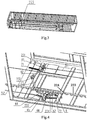
Fig. 3 is a schematic view schematic the bottom structure of a tunnel B in the present disclosure; -
Fig. 4 is a schematic view of a movable tunnel braking system according to the embodiment of the present disclosure; -
Fig. 5 is a schematic view showing the bottom structure of a tunnel C in the embodiment of the present invention; -
Fig. 6 is a schematic structural view of a main hinged rod in the embodiment of the present disclosure; -
Fig. 7 is a schematic view of the retracting wire rope being relaxed; -
Fig. 8 is a schematic view of the retracting wire rope being broken; -
Fig. 9 is a schematic view of the tensile wire rope being relaxed; -
Fig. 10 is a schematic view of the tensile wire rope being broken. - In the drawings, 1. rotunda; 21. tunnel A; 22. tunnel B; 221. first movable pulley; 222. second movable pulley; 223. brake plate; 224. brake slot; 23. tunnel C; 51. retracting
wire rope 52. tensile wire rope; 61. first hinged rod; 62. second hinged rod; 63. third hinged rod; 64. fourth hinged rod; 65. connecting bolt; 66. main hinged rod; 661. connectinghandle 662. fixing cover; 663. intermediate hinged shaft; 67. brake pin; 671. striking rod; 71. tensile spring; 72. tensile spring; 73. positioning spring; 9. positioning stop plate; 231. mechanical blocking portion; 232. first hinged seat; 233. mechanical blocking portion; 234. second hinged seat. - Now, the exemplary embodiments will be described more fully with reference to the accompany drawings. However, the exemplary embodiments can be implemented in various forms and should not be construed as limited to the embodiments set forth herein. Instead, these embodiments are provided so that this disclosure will be thorough and complete, and the concept of the exemplary embodiment will fully conveyed to those skilled in the art. Same reference signs denote the same or similar structures in the accompany drawings, and thus the detailed description thereof will be omitted.
- Referring to
Fig. 3 and Fig. 4 , an embodiment of the present disclosure discloses a movable tunnel braking system. The movable tunnel braking system is used for a passenger boarding bridge shown inFig. 1 and Fig. 2 , wherein the passenger boarding bridge includes a plurality of tunnels that are sequentially sleeve-connected with one another, and atensile wire rope 52 and aretracting wire rope 51 that are connected to the plurality of tunnels. The movable tunnel braking system includes abrake plate 223, abrake pin 67, and a triggering device, wherein thebrake plate 223 is fixedly disposed at a first tunnel, and thebrake pin 67 is movably disposed at a second tunnel that is sleeve-connected with the first tunnel. - In this embodiment, the first tunnel is a
tunnel B 22, and the second tunnel is atunnel C 23. However, it should be noted that the "first tunnel" and the "second tunnel" in this embodiment are merely used to indicate one of two tunnels that are adjacent and sleeve-connected with each other, but not limit the tunnel. For example, in other embodiments of the present disclosure, the first tunnel may also represent thetunnel C 23 and the second tunnel is thetunnel B 22. At the same time, the number of tunnels of the passenger boarding bridge is not limited to two, but may also be three or more. - Referring to
Fig. 4 , thebrake plate 223 is substantially an elongated strip-shaped steel sheet, on which a plurality ofbrake slots 224 are disposed. In this embodiment, the structure of thebrake slot 224 is substantially a waist-shaped hole. However, it should be appreciated for the person skilled in the art that the structure of thebrake slot 224 is merely exemplary, but not limit to the specific structure. In the other embodiments of the present disclosure, thebrake slot 224 may also be a circular slot, a square slot, a trapezoidal slot or a V-shaped slot and the other shapes. - The
brake pin 67 may be used to combine with thebrake slot 224 at thebrake plate 223. That is to say, thebrake pin 67 may be protruded into thebrake slot 224 to combine with thebrake slot 224 together, in this way, the relative movement between the first tunnel and the second tunnel may be restricted, so as to ensure the safety of people in the tunnel. Thebrake pin 67 may be triggered by a triggering device to perform the corresponding action of combining with thebrake slot 224. It should be understood by the person skilled in the art that for the present disclosure, the specific action modes of thebrake pin 67 are not limited. For example, thebrake pin 67 may be slidably disposed at the second tunnel, and may slide into thebrake slot 224. In this embodiment, thebrake pin 67 is hinged to the second tunnel, by rotating thebrake pin 67, a distal end of thebrake pin 67 may enter into thebrake slot 224. - Referring to
Fig. 4 to Fig. 10 , the triggering device includes a mechanical blocking portion, a linkage mechanism, and a tensile spring. The mechanical blocking portion is fixedly disposed at the second tunnel. The linkage mechanism is movably disposed at the second tunnel, and connected to one end of thetensile wire rope 52 or theretracting wire rope 51. The linkage mechanism abuts against the mechanical blocking portion under the action of a tensile force of thetensile wire rope 52 or theretracting wire rope 51. The two ends of the tensile spring are respectively connected to the linkage mechanism and the second tunnel, so that when thetensile wire rope 52 or theretracting wire rope 51 is broken, the linkage mechanism is driven to move and drives thebrake pin 67 to combine with thebrake slot 224, to brake the first tunnel and the second tunnel. - Furthermore, the triggering device will be described in detail. For the movable tunnel braking system of the present disclosure, the number of the
brake pin 67 and the triggering device may be adjusted as needed. In one embodiment of the present disclosure, thebrake pin 67 and the triggering device each may be configured in two, and the linkage mechanisms of the two triggering devices are respectively connected to thetensile wire rope 52 and theretracting wire rope 51. The linkage mechanism of each of the triggering devices is connected to one of the brake pins 67. - In another embodiment of the present disclosure, the number of the
brake pin 67 and the triggering device may be only one, so that the linkage mechanism of the triggering device is connected to thetensile wire rope 52 or theretracting wire rope 51. One set of movable tunnel braking system may detect breakage of thetensile wire rope 52 or theretracting wire rope 51. Two sets of the movable tunnel braking systems may be provided to detect the state of thetensile wire rope 52 and theretracting wire rope 51. - In this embodiment, the number of the triggering devices is two. The linkage mechanisms of the two triggering devices are respectively connected to one end of the
tensile wire rope 52 and theretracting wire rope 51. And the two linkage mechanisms are also connected to thesame brake pin 67. In this way, thetensile wire rope 52 and theretracting wire rope 51 may be detected, and may be broken by the action of onebrake pin 67, to improve reliability of the action while reducing the number of the parts. Referring toFig. 4 andFig. 5 , in this embodiment, one second hingedseat 234 is disposed at the second tunnel, and thebrake pin 67 is hinged on the second hingedseat 234. Apositioning spring 73 for providing a tension for thebrake pin 67 is provided at the second tunnel, wherein a positioning stop plate 9 is provided on the second hingedseat 234, astriking rod 671 is provided at thebrake pin 67, and the two ends of thepositioning spring 73 are respectively connected to thestriking rod 671 and the positioning stop plate 9. Thepositioning spring 73 may disengage thebrake pin 67 from thebrake slot 224, that is, under the action of the tension of thepositioning spring 73, thestriking rod 671 is in contact with the positioning stop plate 9, so that thebrake pin 67 may be positioned at a place that is disengaged away from thebrake slot 224. In this place, thebrake pin 67 does not affect the movement between the first tunnel and the second tunnel. Only when thetensile wire rope 52 or theretracting wire rope 51 is broken, thebrake pin 67 will be driven by the triggering device to overcome the function of a tension force of thepositioning spring 73 to combine with thebrake slot 224. - Referring to
Fig. 4 , the configuration of the linkage mechanism in the embodiment of the present disclosure will be further described. In this embodiment, the linkage mechanism presents two structures, wherein the linkage mechanism with a first structure is presented as follows: the linkage mechanism includes a first hingedseat 232, a first hingedrod 61, a second hingedrod 62, a third hingedrod 63, and a fourth hingedrod 64. The first hingedseat 232 is fixedly disposed at the second tunnel. The first hingedrod 61 has one end connected to thetensile wire rope 52 or theretracting wire rope 51, and the other end hinged to the second hingedrod 62. The second hingedrod 62 has one end hinged to the first hingedseat 232 and the other end used to hinge to the first hingedrod 61 and abut against amechanical blocking portion 231. The third hingedrod 63 has one end hinged to the first hingedseat 232. Both ends of the fourth hingedrod 64 are hinged to the third hingedrod 63 and thebrake pin 67, respectively. The second hingedrod 62 is connected to one end of atensile spring 71. The other end of thetensile spring 71 is connected to the second tunnel. After the second hingedrod 62 is rotated by a certain angle a, the third hingedrod 63 may be driven to rotate to drive the fourth hingedrod 64 to move, and finally the fourth hingedrod 64 drives thebrake pin 67 to combine with thebrake slot 224. The second hingedrod 62 rotates at a certain angle a of 5° ≤a≤30° , that is to say, when the second hingedrod 62 rotates within a certain angle a, the third hingedrod 63 is not rotated, and thereby avoiding false operation. In this embodiment, the linkage mechanism with the first structure is used to connect theretracting wire rope 51, but it should be noted that the linkage mechanism with the first structure may also be used to connect thetensile wire rope 52. - Referring to
Fig. 4 andFig. 6 , a linkage mechanism with the second structure is presented as follows: the linkage mechanism includes a main hingedrod 66, an intermediate hingedshaft 663, and a connectingbolt 65. The main hingedrod 66 has one end that is coaxially hinged with thebrake pin 67, and the other end that is in contact with amechanical blocking portion 233. The main hingedrod 66 is also connected to atensile spring 72 disposed at the second tunnel. The intermediate hingedshaft 663 is hinged to the main hingedrod 66. The connectingbolt 65 has one end that is connected to thetensile wire rope 52 or theretracting wire rope 51, and the other end that is connected to the intermediate hingedshaft 663. That is to say, only one main hingedrod 66 may be used, to simplify the structure of the linkage mechanism. Further, referring toFig. 6 , the main hingedrod 66 includes abody 664 and a connectinghandle 661 disposed at one end of thebody 664. The connectinghandle 661 is coaxially hinged with thebrake pin 67. The body is rotated by a certain angle b to contact with thebrake pin 67 so as to drive thebrake pin 67 to combine with thebrake slot 224. A fixingcover 662 is also fixedly connected to the body. The intermediate hingedshaft 663 is hinged between the fixingcover 662 and the body. The main hingedrod 66 is rotated by a certain angle b of 5° ≤b≤30° , that is to say, when the main hingedrod 66 rotates within a certain angle b , thebrake pin 67 is not rotated, and thereby avoiding false operation. In this embodiment, the main hingedrod 66 of the second linkage mechanism is connected to thetensile wire rope 52, however, it should be noted that the second linkage mechanism may also be used on theretracting wire rope 51. - The linkage mechanisms with the two structures as above mentioned may be used independently or together. In this embodiment, the first linkage mechanism and the second linkage mechanism are simultaneously used.
- Referring to
Fig. 7 , when thetensile wire rope 52 is in a tensioned state, theretracting wire rope 51 may be in a certain relaxed state under some working conditions, but theretracting wire rope 51 is not broken, and thereby does not need to brake. At this time, although thetensile spring 71 may rotate the second hingedrod 62, the rotational angle of the second hingedrod 62 does not exceed the range of the angle a, so that the second hingedrod 62 may not rotate the third hingedrod 63, and thereby avoiding accidental combination between thebrake pin 67 and thebrake slot 224 on thebrake plate 223 to ensures security. - Referring to
Fig. 8 , when theretracting wire rope 51 is broken, thetensile spring 71 drives the second hingedrod 62 to rotate beyond the range of the angle a, so that the second hingedrod 62 may drive the third hingedrod 63 to start rotating, and finally thebrake pin 67 is combined together with thebrake slot 224 at thebrake plate 223 to brake the first tunnel and the second tunnel. - Referring to
Fig. 9 , when theretracting wire rope 51 is in a tensioned state, thetensile wire rope 52 may be in a certain relaxed state under some operating conditions, but thetensile wire rope 52 is not broken and thus does not need to brake. At this time, although thetensile spring 72 may rotate the main hingedrod 66, the rotational angle of the main hingedrod 66 does not exceed the range of the angle b. Thereby, the main hingedrod 66 may not rotate thebrake pin 67, to avoid the accident combination of thebrake pin 67 and thebrake slot 224, so as to ensure security. - Referring to
Fig. 10 , when thetensile wire rope 52 is broken, thetensile spring 72 drives the main hingedrod 66 to rotate beyond the range of the angle b, so that the main hingedrod 66 may start rotating thebrake pin 67, and finally thebrake pin 67 and thebrake slot 224 on thebrake plate 223 are combined with each other, to brake the first tunnel and the second tunnel. - Referring to
Fig. 4 , atravel switch 8 may also be disposed at the second tunnel. The travel switch is used to detect whether thebrake pin 67 is combined with thebrake slot 224 or not. When thebrake pin 67 is combined with thebrake slot 224, thebrake pin 67 may just trigger thetravel switch 8. Thetravel switch 8 is triggered to generate a detection signal which can be transmitted to a control system of the passenger boarding bridge. After receiving the detection signal, the control system may stop movement of a lifting column and a horizontal drive unit. - The movable tunnel braking system of the present disclosure, a braking process may be completely realized by means of a mechanical structure, without using any electrical component, to avoid unreliability of the electrical components. The electrical components only play an auxiliary function of transmitting detection signals to the control system of the passenger boarding bridge. Thus, the movable tunnel braking system has an extremely high reliability, and can be braked reliably even in the event of an unexpected power failure.
- The embodiment of the present disclosure further discloses a passenger boarding bridge having the movable tunnel braking system, which may have three or more tunnels.
Claims (12)
- A movable tunnel braking system for a passenger boarding bridge, the passenger boarding bridge comprising a plurality of tunnels (22, 23) sleeve-connected sequentially and a tensile wire rope (52) and a retracting wire rope (51) that are connected to the plurality of the tunnels (22, 23), wherein the movable tunnel braking system comprises:a brake plate (223) that is configured to be fixedly disposed at a first tunnel (22) of the plurality of tunnels (22, 23), wherein the brake plate (223) is provided with a plurality of brake slots (224);a brake pin (67) that is configured to be movably disposed at a second tunnel (23) of the plurality of tunnels (22, 23), which is sleeve-connected with the first tunnel (22) and configured to be combined with the brake slot (224); anda triggering device, comprising:a mechanical blocking portion (231, 233) that is configured to be fixedly disposed at the second tunnel (23);a linkage mechanism that is configured to be movably disposed at the second tunnel (23), and is configured to be connected to one end of the tensile wire rope (52) or the retracting wire rope (51), wherein the linkage mechanism is configured to abut against the mechanical blocking portion (231, 233) under action of a tension of the tensile wire rope (52) or the retracting wire rope (51); anda tensile spring (71, 72) that has two ends respectively connected to the linkage mechanism and configured to be connected to the second tunnel (23), so that when the tensile wire rope (52) or the retracting wire rope (51) is broken, the linkage mechanism is driven to move and drives the brake pin (67) to combine with the brake slot (224), to brake the first tunnel (22) and the second tunnel (23).
- The movable tunnel braking system according to claim 1, wherein the brake pin (67) is configured to be hinged to the second tunnel (23); two brake pins (67) and two triggering devices are provided; the two linkage mechanisms of the two triggering devices are configured to be connected to one end of the tensile wire rope (52) and the retracting wire rope (51), respectively; and the two linkage mechanisms of the two triggering devices are connected to one of the brake pins (67), respectively.
- The movable tunnel braking system according to claim 1, wherein the brake pin (67) is configured to be hinged to the second tunnel (23); further comprising a positioning spring (73) configured to be provided on the second tunnel (23) that provides a pulling force for the brake pin (67) to disconnect the brake pin (67) from the brake slot (224); wherein two triggering devices are provided; wherein the two linkage mechanisms of the two triggering devices are configured to be connected to one end of the tensile wire rope (52) and to the retracting wire rope (51), respectively; and wherein the two linkage mechanisms of the two triggering devices are connected to the same brake pin (67).
- The movable tunnel braking system of claim 3, wherein the linkage mechanism comprises:a first hinged seat (232) that is configured to be fixedly disposed at the second tunnel (23);a first hinged rod (61) that is configured to be connected to the tensile wire rope (52) or the retracting wire rope (51);a second hinged rod (62) that has one end hinged to the first hinged seat (232) and the other end hinged to the first hinged rod (61) and capable of abutting against the mechanical blocking portion (231), the tensile spring (71) being connected to the second hinged rod (62);a third hinged rod (63) having one end hinged to the first hinged seat (232);a fourth hinged rod (64) having two ends respectively hinged to the third hinged rod (63) and the brake pin (67); whereinthe second hinged rod (62) is configured to be rotated by a certain angle a to drive the third hinged rod (63) to rotate, such that the third hinged rod (63) drives the fourth hinged rod (64) to move, and the fourth hinged rod (64) drives the brake pin (67) to combine with the brake slot (224).
- The movable tunnel braking system of claim 4, wherein the certain angle a is in a range of 5° to 30°.
- The movable tunnel braking system of claim 3, wherein the linkage mechanism comprises:a main hinged rod (66) that has one end coaxially hinged with the brake pin (67) and the other end in contact with the mechanical blocking portion (233), the main hinged rod (66) being connected to the tensile spring (73);an intermediate hinged shaft (663) that is hinged to the main hinged rod (66); anda connecting bolt (65) that has one end configured to be connected to the tensile wire rope (52) or the retracting wire rope (51) and the other end connected to the intermediate hinged shaft (663).
- The movable tunnel braking system according to claim 6, wherein the main hinged rod (66) comprises a body (664) and a connecting handle (661) disposed at one end of the body (664); the connecting handle (661) is coaxially hinged with the brake pin (67); the body (664) is configured to be rotated by a certain angle b to contact with the brake pin (67) so as to drive the brake pin (67) to be combined with the brake slot (224).
- The movable tunnel braking system of claim 7, wherein the certain angle b is in a range of 5° to 30°.
- The movable tunnel braking system according to claim 1, wherein the brake slot (224) is a waist-shaped slot, a circular slot, a square slot, a trapezoidal slot or a V-shaped slot.
- The movable tunnel braking system according to claim 1, further comprising a travel switch (8) for detecting whether the brake pin (67) is combined with the brake slot (224).
- A passenger boarding bridge, comprising the movable tunnel braking system. according to any one of claims 1 to 10.
- The passenger boarding bridge according to claim 11, wherein the passenger boarding bridge has three tunnels (21, 22, 23).
Applications Claiming Priority (2)
| Application Number | Priority Date | Filing Date | Title |
|---|---|---|---|
| CN201610810478.XA CN107792386B (en) | 2016-09-06 | 2016-09-06 | Active aisle braking system and boarding bridge |
| PCT/CN2017/081263 WO2018045757A1 (en) | 2016-09-06 | 2017-04-20 | Movable walkway braking system and passenger boarding bridge |
Publications (3)
| Publication Number | Publication Date |
|---|---|
| EP3511250A1 EP3511250A1 (en) | 2019-07-17 |
| EP3511250A4 EP3511250A4 (en) | 2020-05-27 |
| EP3511250B1 true EP3511250B1 (en) | 2021-12-01 |
Family
ID=61530973
Family Applications (1)
| Application Number | Title | Priority Date | Filing Date |
|---|---|---|---|
| EP17847931.7A Active EP3511250B1 (en) | 2016-09-06 | 2017-04-20 | Movable tunnel braking system and passenger boarding bridge |
Country Status (5)
| Country | Link |
|---|---|
| US (1) | US10724586B2 (en) |
| EP (1) | EP3511250B1 (en) |
| CN (1) | CN107792386B (en) |
| ES (1) | ES2907594T3 (en) |
| WO (1) | WO2018045757A1 (en) |
Family Cites Families (18)
| Publication number | Priority date | Publication date | Assignee | Title |
|---|---|---|---|---|
| US3693204A (en) * | 1970-09-24 | 1972-09-26 | Boothe Airside Services | Closure apparatus |
| US3722017A (en) * | 1971-07-26 | 1973-03-27 | Gen Steel Ind Inc | Over-the-wing aircraft loading bridge |
| US3859481A (en) * | 1973-10-29 | 1975-01-07 | Stephen B Sprague | Telescoping power support |
| DE2701634A1 (en) * | 1977-01-17 | 1978-07-20 | Vorrichtungsbau Petersen | Folding ladder for use on side of boat - has telescopic mounting brackets with stops to limit swing of hinged lower section |
| US4222140A (en) * | 1979-02-23 | 1980-09-16 | F. C. Schaffer & Associates, Inc. | Boarding platform |
| US4344200A (en) * | 1980-09-25 | 1982-08-17 | Abex Corporation | Bridge brake system |
| US6678910B2 (en) * | 2001-10-19 | 2004-01-20 | Dave W. Smith | Fully floating gangway |
| EP2284079B1 (en) * | 2007-12-18 | 2013-02-20 | Otis Elevator Company | Cable tray for telescopically retractable boarding bridge |
| JP4620747B2 (en) * | 2008-01-31 | 2011-01-26 | 三菱重工交通機器エンジニアリング株式会社 | Boarding bridge |
| CN201610222U (en) * | 2010-01-21 | 2010-10-20 | 蒂森克虏伯机场系统(中山)有限公司 | Boarding bridge with chain breakage protection |
| US8266750B2 (en) * | 2010-03-24 | 2012-09-18 | Gatelink Aircraft Boarding Systems, Inc. | Microbridges for regional aircraft and methods of using same |
| CN201777388U (en) * | 2010-08-04 | 2011-03-30 | 蒂森克虏伯机场系统(中山)有限公司 | A three-channel boarding bridge equipped with a detection brake device |
| JP5759299B2 (en) | 2011-08-02 | 2015-08-05 | 新明和工業株式会社 | Boarding bridge |
| ES2412607B1 (en) | 2013-05-06 | 2014-05-12 | Thyssenkrupp Airport Systems, S.A. | Stop system for the cockpit of aircraft and ships drive gateways |
| CN204415745U (en) | 2015-01-16 | 2015-06-24 | 深圳中集天达空港设备有限公司 | Front edge of airport pickup port fork type self-locking device and connecting bridge |
| CN205396576U (en) * | 2016-03-01 | 2016-07-27 | 中国国际海运集装箱(集团)股份有限公司 | Connecting bridge and active channel braking system thereof |
| CN106428611B (en) | 2016-09-30 | 2019-02-05 | 美迪斯智能装备有限公司 | Auxiliary braking system for boarding bridge |
| CN206141864U (en) | 2016-09-30 | 2017-05-03 | 美迪斯智能装备有限公司 | Boarding Bridge with Linkage Wire Rope Safety Brake |
-
2016
- 2016-09-06 CN CN201610810478.XA patent/CN107792386B/en active Active
-
2017
- 2017-04-20 EP EP17847931.7A patent/EP3511250B1/en active Active
- 2017-04-20 ES ES17847931T patent/ES2907594T3/en active Active
- 2017-04-20 US US16/330,915 patent/US10724586B2/en active Active
- 2017-04-20 WO PCT/CN2017/081263 patent/WO2018045757A1/en not_active Ceased
Also Published As
| Publication number | Publication date |
|---|---|
| WO2018045757A1 (en) | 2018-03-15 |
| US20200124120A1 (en) | 2020-04-23 |
| CN107792386A (en) | 2018-03-13 |
| ES2907594T3 (en) | 2022-04-25 |
| CN107792386B (en) | 2020-07-03 |
| EP3511250A1 (en) | 2019-07-17 |
| US10724586B2 (en) | 2020-07-28 |
| EP3511250A4 (en) | 2020-05-27 |
Similar Documents
| Publication | Publication Date | Title |
|---|---|---|
| CN109665429B (en) | Car door layer door system based on safety loop detection | |
| CN107473050B (en) | Control method of anti-falling safety system of car type elevator | |
| US10393628B2 (en) | Track vehicle collision testing device and track vehicle collision testing method | |
| AU2003209906A1 (en) | Shaft monitoring system for an elevator | |
| AU2020201936B2 (en) | Locomotive parking brake | |
| CN101472825A (en) | Safety device for ensuring minimum space on top or bottom of elevator well channel when examining as well as elevator with the safety device | |
| JP2013189283A (en) | Stop device and elevator with the same | |
| CN101516725A (en) | Locking and unlocking system for the cockpit door of an aircraft and door with such a system | |
| EP3135620B1 (en) | Elevator | |
| CN103420247B (en) | About the safety device of accidental movement of elevator cage | |
| CN207030659U (en) | A kind of anti-accidental movement device of fool proof elevator | |
| KR101548153B1 (en) | Lifter for construnction works | |
| US10724586B2 (en) | Movable tunnel braking system and passenger boarding bridge | |
| CN109071167B (en) | Device for releasing the operating brake of an elevator | |
| CN102963851B (en) | The brake gear of sliding hopper and use the aerial ladder of brake gear of this sliding hopper | |
| CN203529648U (en) | Bi-directional speed limiter | |
| US20110168844A1 (en) | System for disconnecting a fuel transfer boom | |
| US7819229B2 (en) | Elevator safety system | |
| CN205396576U (en) | Connecting bridge and active channel braking system thereof | |
| WO2016093582A1 (en) | Device and method for preventing escalator from going in reverse | |
| EP1524234A1 (en) | Elevator system | |
| CN104129704A (en) | Door cutter structure with mechanical lock device | |
| CN203451098U (en) | Windproof cable device with limiting switch | |
| CN209958980U (en) | Two-in-one device with unlocking and isolating functions for rail transit vehicle door system | |
| KR20170070617A (en) | Safety brake control apparatus for emergency stop of escalator |
Legal Events
| Date | Code | Title | Description |
|---|---|---|---|
| STAA | Information on the status of an ep patent application or granted ep patent |
Free format text: STATUS: THE INTERNATIONAL PUBLICATION HAS BEEN MADE |
|
| PUAI | Public reference made under article 153(3) epc to a published international application that has entered the european phase |
Free format text: ORIGINAL CODE: 0009012 |
|
| STAA | Information on the status of an ep patent application or granted ep patent |
Free format text: STATUS: REQUEST FOR EXAMINATION WAS MADE |
|
| 17P | Request for examination filed |
Effective date: 20190405 |
|
| AK | Designated contracting states |
Kind code of ref document: A1 Designated state(s): AL AT BE BG CH CY CZ DE DK EE ES FI FR GB GR HR HU IE IS IT LI LT LU LV MC MK MT NL NO PL PT RO RS SE SI SK SM TR |
|
| AX | Request for extension of the european patent |
Extension state: BA ME |
|
| DAV | Request for validation of the european patent (deleted) | ||
| DAX | Request for extension of the european patent (deleted) | ||
| A4 | Supplementary search report drawn up and despatched |
Effective date: 20200430 |
|
| RIC1 | Information provided on ipc code assigned before grant |
Ipc: B64F 1/305 20060101AFI20200423BHEP |
|
| GRAP | Despatch of communication of intention to grant a patent |
Free format text: ORIGINAL CODE: EPIDOSNIGR1 |
|
| STAA | Information on the status of an ep patent application or granted ep patent |
Free format text: STATUS: GRANT OF PATENT IS INTENDED |
|
| GRAJ | Information related to disapproval of communication of intention to grant by the applicant or resumption of examination proceedings by the epo deleted |
Free format text: ORIGINAL CODE: EPIDOSDIGR1 |
|
| GRAP | Despatch of communication of intention to grant a patent |
Free format text: ORIGINAL CODE: EPIDOSNIGR1 |
|
| RAP1 | Party data changed (applicant data changed or rights of an application transferred) |
Owner name: SHENZHEN CIMC-TIANDA AIRPORT SUPPORT LTD. |
|
| INTG | Intention to grant announced |
Effective date: 20210706 |
|
| INTG | Intention to grant announced |
Effective date: 20210719 |
|
| GRAS | Grant fee paid |
Free format text: ORIGINAL CODE: EPIDOSNIGR3 |
|
| GRAA | (expected) grant |
Free format text: ORIGINAL CODE: 0009210 |
|
| STAA | Information on the status of an ep patent application or granted ep patent |
Free format text: STATUS: THE PATENT HAS BEEN GRANTED |
|
| AK | Designated contracting states |
Kind code of ref document: B1 Designated state(s): AL AT BE BG CH CY CZ DE DK EE ES FI FR GB GR HR HU IE IS IT LI LT LU LV MC MK MT NL NO PL PT RO RS SE SI SK SM TR |
|
| REG | Reference to a national code |
Ref country code: GB Ref legal event code: FG4D |
|
| REG | Reference to a national code |
Ref country code: AT Ref legal event code: REF Ref document number: 1451553 Country of ref document: AT Kind code of ref document: T Effective date: 20211215 Ref country code: CH Ref legal event code: EP |
|
| REG | Reference to a national code |
Ref country code: IE Ref legal event code: FG4D |
|
| REG | Reference to a national code |
Ref country code: DE Ref legal event code: R096 Ref document number: 602017050365 Country of ref document: DE |
|
| REG | Reference to a national code |
Ref country code: NL Ref legal event code: FP |
|
| REG | Reference to a national code |
Ref country code: LT Ref legal event code: MG9D |
|
| REG | Reference to a national code |
Ref country code: AT Ref legal event code: MK05 Ref document number: 1451553 Country of ref document: AT Kind code of ref document: T Effective date: 20211201 |
|
| REG | Reference to a national code |
Ref country code: ES Ref legal event code: FG2A Ref document number: 2907594 Country of ref document: ES Kind code of ref document: T3 Effective date: 20220425 |
|
| PG25 | Lapsed in a contracting state [announced via postgrant information from national office to epo] |
Ref country code: RS Free format text: LAPSE BECAUSE OF FAILURE TO SUBMIT A TRANSLATION OF THE DESCRIPTION OR TO PAY THE FEE WITHIN THE PRESCRIBED TIME-LIMIT Effective date: 20211201 Ref country code: LT Free format text: LAPSE BECAUSE OF FAILURE TO SUBMIT A TRANSLATION OF THE DESCRIPTION OR TO PAY THE FEE WITHIN THE PRESCRIBED TIME-LIMIT Effective date: 20211201 Ref country code: FI Free format text: LAPSE BECAUSE OF FAILURE TO SUBMIT A TRANSLATION OF THE DESCRIPTION OR TO PAY THE FEE WITHIN THE PRESCRIBED TIME-LIMIT Effective date: 20211201 Ref country code: BG Free format text: LAPSE BECAUSE OF FAILURE TO SUBMIT A TRANSLATION OF THE DESCRIPTION OR TO PAY THE FEE WITHIN THE PRESCRIBED TIME-LIMIT Effective date: 20220301 Ref country code: AT Free format text: LAPSE BECAUSE OF FAILURE TO SUBMIT A TRANSLATION OF THE DESCRIPTION OR TO PAY THE FEE WITHIN THE PRESCRIBED TIME-LIMIT Effective date: 20211201 |
|
| PG25 | Lapsed in a contracting state [announced via postgrant information from national office to epo] |
Ref country code: SE Free format text: LAPSE BECAUSE OF FAILURE TO SUBMIT A TRANSLATION OF THE DESCRIPTION OR TO PAY THE FEE WITHIN THE PRESCRIBED TIME-LIMIT Effective date: 20211201 Ref country code: PL Free format text: LAPSE BECAUSE OF FAILURE TO SUBMIT A TRANSLATION OF THE DESCRIPTION OR TO PAY THE FEE WITHIN THE PRESCRIBED TIME-LIMIT Effective date: 20211201 Ref country code: NO Free format text: LAPSE BECAUSE OF FAILURE TO SUBMIT A TRANSLATION OF THE DESCRIPTION OR TO PAY THE FEE WITHIN THE PRESCRIBED TIME-LIMIT Effective date: 20220301 Ref country code: LV Free format text: LAPSE BECAUSE OF FAILURE TO SUBMIT A TRANSLATION OF THE DESCRIPTION OR TO PAY THE FEE WITHIN THE PRESCRIBED TIME-LIMIT Effective date: 20211201 Ref country code: HR Free format text: LAPSE BECAUSE OF FAILURE TO SUBMIT A TRANSLATION OF THE DESCRIPTION OR TO PAY THE FEE WITHIN THE PRESCRIBED TIME-LIMIT Effective date: 20211201 Ref country code: GR Free format text: LAPSE BECAUSE OF FAILURE TO SUBMIT A TRANSLATION OF THE DESCRIPTION OR TO PAY THE FEE WITHIN THE PRESCRIBED TIME-LIMIT Effective date: 20220302 |
|
| PG25 | Lapsed in a contracting state [announced via postgrant information from national office to epo] |
Ref country code: SM Free format text: LAPSE BECAUSE OF FAILURE TO SUBMIT A TRANSLATION OF THE DESCRIPTION OR TO PAY THE FEE WITHIN THE PRESCRIBED TIME-LIMIT Effective date: 20211201 Ref country code: SK Free format text: LAPSE BECAUSE OF FAILURE TO SUBMIT A TRANSLATION OF THE DESCRIPTION OR TO PAY THE FEE WITHIN THE PRESCRIBED TIME-LIMIT Effective date: 20211201 Ref country code: RO Free format text: LAPSE BECAUSE OF FAILURE TO SUBMIT A TRANSLATION OF THE DESCRIPTION OR TO PAY THE FEE WITHIN THE PRESCRIBED TIME-LIMIT Effective date: 20211201 Ref country code: PT Free format text: LAPSE BECAUSE OF FAILURE TO SUBMIT A TRANSLATION OF THE DESCRIPTION OR TO PAY THE FEE WITHIN THE PRESCRIBED TIME-LIMIT Effective date: 20220401 Ref country code: EE Free format text: LAPSE BECAUSE OF FAILURE TO SUBMIT A TRANSLATION OF THE DESCRIPTION OR TO PAY THE FEE WITHIN THE PRESCRIBED TIME-LIMIT Effective date: 20211201 Ref country code: CZ Free format text: LAPSE BECAUSE OF FAILURE TO SUBMIT A TRANSLATION OF THE DESCRIPTION OR TO PAY THE FEE WITHIN THE PRESCRIBED TIME-LIMIT Effective date: 20211201 |
|
| REG | Reference to a national code |
Ref country code: DE Ref legal event code: R097 Ref document number: 602017050365 Country of ref document: DE |
|
| PG25 | Lapsed in a contracting state [announced via postgrant information from national office to epo] |
Ref country code: IS Free format text: LAPSE BECAUSE OF FAILURE TO SUBMIT A TRANSLATION OF THE DESCRIPTION OR TO PAY THE FEE WITHIN THE PRESCRIBED TIME-LIMIT Effective date: 20220401 |
|
| PLBE | No opposition filed within time limit |
Free format text: ORIGINAL CODE: 0009261 |
|
| STAA | Information on the status of an ep patent application or granted ep patent |
Free format text: STATUS: NO OPPOSITION FILED WITHIN TIME LIMIT |
|
| PG25 | Lapsed in a contracting state [announced via postgrant information from national office to epo] |
Ref country code: DK Free format text: LAPSE BECAUSE OF FAILURE TO SUBMIT A TRANSLATION OF THE DESCRIPTION OR TO PAY THE FEE WITHIN THE PRESCRIBED TIME-LIMIT Effective date: 20211201 Ref country code: AL Free format text: LAPSE BECAUSE OF FAILURE TO SUBMIT A TRANSLATION OF THE DESCRIPTION OR TO PAY THE FEE WITHIN THE PRESCRIBED TIME-LIMIT Effective date: 20211201 |
|
| 26N | No opposition filed |
Effective date: 20220902 |
|
| PG25 | Lapsed in a contracting state [announced via postgrant information from national office to epo] |
Ref country code: SI Free format text: LAPSE BECAUSE OF FAILURE TO SUBMIT A TRANSLATION OF THE DESCRIPTION OR TO PAY THE FEE WITHIN THE PRESCRIBED TIME-LIMIT Effective date: 20211201 |
|
| REG | Reference to a national code |
Ref country code: CH Ref legal event code: PL |
|
| GBPC | Gb: european patent ceased through non-payment of renewal fee |
Effective date: 20220420 |
|
| REG | Reference to a national code |
Ref country code: BE Ref legal event code: MM Effective date: 20220430 |
|
| PG25 | Lapsed in a contracting state [announced via postgrant information from national office to epo] |
Ref country code: MC Free format text: LAPSE BECAUSE OF FAILURE TO SUBMIT A TRANSLATION OF THE DESCRIPTION OR TO PAY THE FEE WITHIN THE PRESCRIBED TIME-LIMIT Effective date: 20211201 Ref country code: LU Free format text: LAPSE BECAUSE OF NON-PAYMENT OF DUE FEES Effective date: 20220420 Ref country code: LI Free format text: LAPSE BECAUSE OF NON-PAYMENT OF DUE FEES Effective date: 20220430 Ref country code: GB Free format text: LAPSE BECAUSE OF NON-PAYMENT OF DUE FEES Effective date: 20220420 Ref country code: CH Free format text: LAPSE BECAUSE OF NON-PAYMENT OF DUE FEES Effective date: 20220430 |
|
| PG25 | Lapsed in a contracting state [announced via postgrant information from national office to epo] |
Ref country code: BE Free format text: LAPSE BECAUSE OF NON-PAYMENT OF DUE FEES Effective date: 20220430 |
|
| REG | Reference to a national code |
Ref country code: DE Ref legal event code: R082 Ref document number: 602017050365 Country of ref document: DE Representative=s name: CBDL PATENTANWAELTE GBR, DE Ref country code: DE Ref legal event code: R082 Ref document number: 602017050365 Country of ref document: DE Representative=s name: CBDL PATENTANWAELTE EGBR, DE |
|
| PG25 | Lapsed in a contracting state [announced via postgrant information from national office to epo] |
Ref country code: IE Free format text: LAPSE BECAUSE OF NON-PAYMENT OF DUE FEES Effective date: 20220420 |
|
| PG25 | Lapsed in a contracting state [announced via postgrant information from national office to epo] |
Ref country code: IT Free format text: LAPSE BECAUSE OF NON-PAYMENT OF DUE FEES Effective date: 20220420 |
|
| PG25 | Lapsed in a contracting state [announced via postgrant information from national office to epo] |
Ref country code: IT Free format text: LAPSE BECAUSE OF NON-PAYMENT OF DUE FEES Effective date: 20220420 |
|
| PGRI | Patent reinstated in contracting state [announced from national office to epo] |
Ref country code: IT Effective date: 20220831 |
|
| PG25 | Lapsed in a contracting state [announced via postgrant information from national office to epo] |
Ref country code: HU Free format text: LAPSE BECAUSE OF FAILURE TO SUBMIT A TRANSLATION OF THE DESCRIPTION OR TO PAY THE FEE WITHIN THE PRESCRIBED TIME-LIMIT; INVALID AB INITIO Effective date: 20170420 |
|
| PG25 | Lapsed in a contracting state [announced via postgrant information from national office to epo] |
Ref country code: MK Free format text: LAPSE BECAUSE OF FAILURE TO SUBMIT A TRANSLATION OF THE DESCRIPTION OR TO PAY THE FEE WITHIN THE PRESCRIBED TIME-LIMIT Effective date: 20211201 Ref country code: CY Free format text: LAPSE BECAUSE OF FAILURE TO SUBMIT A TRANSLATION OF THE DESCRIPTION OR TO PAY THE FEE WITHIN THE PRESCRIBED TIME-LIMIT Effective date: 20211201 |
|
| PG25 | Lapsed in a contracting state [announced via postgrant information from national office to epo] |
Ref country code: MT Free format text: LAPSE BECAUSE OF FAILURE TO SUBMIT A TRANSLATION OF THE DESCRIPTION OR TO PAY THE FEE WITHIN THE PRESCRIBED TIME-LIMIT Effective date: 20211201 |
|
| PGFP | Annual fee paid to national office [announced via postgrant information from national office to epo] |
Ref country code: NL Payment date: 20250324 Year of fee payment: 9 |
|
| PGFP | Annual fee paid to national office [announced via postgrant information from national office to epo] |
Ref country code: DE Payment date: 20250417 Year of fee payment: 9 |
|
| PGFP | Annual fee paid to national office [announced via postgrant information from national office to epo] |
Ref country code: ES Payment date: 20250519 Year of fee payment: 9 |
|
| PGFP | Annual fee paid to national office [announced via postgrant information from national office to epo] |
Ref country code: IT Payment date: 20250430 Year of fee payment: 9 |
|
| PG25 | Lapsed in a contracting state [announced via postgrant information from national office to epo] |
Ref country code: TR Free format text: LAPSE BECAUSE OF FAILURE TO SUBMIT A TRANSLATION OF THE DESCRIPTION OR TO PAY THE FEE WITHIN THE PRESCRIBED TIME-LIMIT Effective date: 20211201 |
|
| PGFP | Annual fee paid to national office [announced via postgrant information from national office to epo] |
Ref country code: FR Payment date: 20260325 Year of fee payment: 10 |