EP3511100A1 - Method for processing bevel gear workpieces - Google Patents
Method for processing bevel gear workpieces Download PDFInfo
- Publication number
- EP3511100A1 EP3511100A1 EP18151648.5A EP18151648A EP3511100A1 EP 3511100 A1 EP3511100 A1 EP 3511100A1 EP 18151648 A EP18151648 A EP 18151648A EP 3511100 A1 EP3511100 A1 EP 3511100A1
- Authority
- EP
- European Patent Office
- Prior art keywords
- rolling
- bevel gear
- tool
- workpiece
- rolling process
- Prior art date
- Legal status (The legal status is an assumption and is not a legal conclusion. Google has not performed a legal analysis and makes no representation as to the accuracy of the status listed.)
- Granted
Links
Images


Classifications
-
- B—PERFORMING OPERATIONS; TRANSPORTING
- B23—MACHINE TOOLS; METAL-WORKING NOT OTHERWISE PROVIDED FOR
- B23F—MAKING GEARS OR TOOTHED RACKS
- B23F17/00—Special methods or machines for making gear teeth, not covered by the preceding groups
- B23F17/003—Special methods or machines for making gear teeth, not covered by the preceding groups for dry cutting
-
- B—PERFORMING OPERATIONS; TRANSPORTING
- B23—MACHINE TOOLS; METAL-WORKING NOT OTHERWISE PROVIDED FOR
- B23F—MAKING GEARS OR TOOTHED RACKS
- B23F23/00—Accessories or equipment combined with or arranged in, or specially designed to form part of, gear-cutting machines
- B23F23/02—Loading, unloading or chucking arrangements for workpieces
- B23F23/06—Chucking arrangements
-
- B—PERFORMING OPERATIONS; TRANSPORTING
- B23—MACHINE TOOLS; METAL-WORKING NOT OTHERWISE PROVIDED FOR
- B23F—MAKING GEARS OR TOOTHED RACKS
- B23F5/00—Making straight gear teeth involving moving a tool relatively to a workpiece with a rolling-off or an enveloping motion with respect to the gear teeth to be made
- B23F5/12—Making straight gear teeth involving moving a tool relatively to a workpiece with a rolling-off or an enveloping motion with respect to the gear teeth to be made by planing or slotting
- B23F5/16—Making straight gear teeth involving moving a tool relatively to a workpiece with a rolling-off or an enveloping motion with respect to the gear teeth to be made by planing or slotting the tool having a shape similar to that of a spur wheel or part thereof
- B23F5/163—Making straight gear teeth involving moving a tool relatively to a workpiece with a rolling-off or an enveloping motion with respect to the gear teeth to be made by planing or slotting the tool having a shape similar to that of a spur wheel or part thereof the tool and workpiece being in crossed axis arrangement, e.g. skiving, i.e. "Waelzschaelen"
-
- B—PERFORMING OPERATIONS; TRANSPORTING
- B23—MACHINE TOOLS; METAL-WORKING NOT OTHERWISE PROVIDED FOR
- B23F—MAKING GEARS OR TOOTHED RACKS
- B23F9/00—Making gears having teeth curved in their longitudinal direction
- B23F9/02—Making gears having teeth curved in their longitudinal direction by grinding
- B23F9/025—Making gears having teeth curved in their longitudinal direction by grinding with a face-mill-type, i.e. cup-shaped, grinding wheel
-
- B—PERFORMING OPERATIONS; TRANSPORTING
- B23—MACHINE TOOLS; METAL-WORKING NOT OTHERWISE PROVIDED FOR
- B23F—MAKING GEARS OR TOOTHED RACKS
- B23F9/00—Making gears having teeth curved in their longitudinal direction
- B23F9/08—Making gears having teeth curved in their longitudinal direction by milling, e.g. with helicoidal hob
- B23F9/10—Making gears having teeth curved in their longitudinal direction by milling, e.g. with helicoidal hob with a face-mill
- B23F9/105—Making gears having teeth curved in their longitudinal direction by milling, e.g. with helicoidal hob with a face-mill with continuous indexing, i.e. with continuous work rotation
-
- Y—GENERAL TAGGING OF NEW TECHNOLOGICAL DEVELOPMENTS; GENERAL TAGGING OF CROSS-SECTIONAL TECHNOLOGIES SPANNING OVER SEVERAL SECTIONS OF THE IPC; TECHNICAL SUBJECTS COVERED BY FORMER USPC CROSS-REFERENCE ART COLLECTIONS [XRACs] AND DIGESTS
- Y02—TECHNOLOGIES OR APPLICATIONS FOR MITIGATION OR ADAPTATION AGAINST CLIMATE CHANGE
- Y02P—CLIMATE CHANGE MITIGATION TECHNOLOGIES IN THE PRODUCTION OR PROCESSING OF GOODS
- Y02P70/00—Climate change mitigation technologies in the production process for final industrial or consumer products
- Y02P70/10—Greenhouse gas [GHG] capture, material saving, heat recovery or other energy efficient measures, e.g. motor control, characterised by manufacturing processes, e.g. for rolling metal or metal working
Definitions
- the invention relates to a method for interlocking bevel gear workpieces.
- the respective profile rolling range results from the geometric properties of the bevel gear to be toothed and from the process used for gear cutting. That the profile rolling area is a size calculated by e.g. can be determined in the context of the interpretation.
- the profile rolling area is thus a fixed process variable of the toothing process of the respective bevel gear.
- the pitch may even be slightly longer to provide a small margin of safety.
- This initial contact occurs at the head of the workpiece and depending on the rolling direction (when rolling from toe to heel) on the toe of the workpiece (Einisselzwinkel toe) or (when rolling from heel to toe) at the heel of the workpiece (Einisselzwinkel heel ).
- Wälzmitte Another point on the Wälzweg or Wälz Symposium is the so-called Wälzmitte. This is by definition the rolling angle at which the design point of the toothing is generated. It does not have to lie exactly in the middle of the Wälzwegs between profile rolling angle toe and Profilülzwinkel heel.
- Rolling in There are no immersion movements during which material is removed.
- the gearing is done only by rolling. It is therefore a pure rolling process.
- the gear tool is moved at full speed out of engagement with the workpiece to full depth.
- Out of engagement here means that a rolling position is approached at Einicalzwinkel toe (when rolling from toe to heel) or Einisselzwinkel heel (when rolling from heel to toe) plus a small safety distance on the Wälzweg.
- the rolling motion starts from here, ie the respective entry angle (plus a safety distance) defines the start of rolling.
- the rolling motion then takes place up to the corresponding profile rolling angle heel (when rolling from toe to heel) or to the corresponding profile rolling angle toe (when rolling from heel to toe).
- the speed of the rolling motion can be constant or variable in this Wälzrea on the Wälzweg.
- Wälzende eg the profile rolling angle heel
- the gear tool is moved out of the gap. If this rolling process is carried out as a single-part method, the partial movement now takes place and the process described is repeated gap-by-gap.
- Grooving is a dip rolling process. Here, at the beginning of the rolling process, it is inserted or dipped. Depending on the direction of rolling, this piercing takes place at the profile rolling angle toe (when rolling from the toe to the heel) or at the profile rolling angle heel (when rolling from the heel to the toe). It is inserted with a safety distance in the diving direction starting in a penetration into the workpiece at the toe or heel to full tooth depth (also called dipping). When the full tooth depth is reached, the piercing movement stops and the rolling motion follows.
- Wälzende is when Einstech76lzen the respective Profilemaschinelzwinkel (Profilisselzwinkel heel for the rolling direction of the toe to the heel or Profileracelzwinkel toe for the rolling direction of the heel to toe).
- the speed of the rolling motion can be constant or variable over the rolling path.
- the gear tool is moved out of the gap. If this diving rolling process is executed as a single part method, now the partial movement takes place and the process repeats gap-by-gap.
- Einstechdoppel bienlzen The Einstechdooppelt bienlzen is also a dip-rolling process. Again, starting from a Wälz ein outside the workpiece is immersed in the workpiece and material removed. Here, the Wälzterrorism between the Profildozenslzwinkel toe and the Profilülzwinkel heel, but not exactly on this. Frequently, the roller center is chosen for immersion (also called grooving). The immersion can be done down to full tooth depth or a slight depth allowance is left, ie the immersion is stopped in the position of the full tooth depth minus a depth allowance. From this point, the rolling motion now takes place in the direction of the toe up to the profile rolling angle toe or in the direction of the heel up to the profile rolling angle heel.
- Double rolling In this process, no immersion movements take place in which material is removed.
- the gearing is done only by rolling. It is therefore a pure rolling process.
- the gear tool is moved in rapid traverse out of engagement with the workpiece to full depth minus a Tiefenaufenstein. Out of engagement here means that a rolling position at Einicalzwinkel toe (when rolling from toe to heel) or at Einisselzwinkel heel (when rolling from heel to toe) plus a small safety distance on the Wälzweg is approached. From here, the rolling motion begins, ie the respective entry angle (plus the safety distance) defines the start of rolling.
- the rolling movement then takes place up to the corresponding profile rolling angle heel (when rolling from the toe to the heel) or until the corresponding profile rolling angle toe (when rolling from the heel to the toe).
- the first rolling motion is usually carried out as roughing and the second rolling as sizing.
- the speed of the rolling motion can be constant or variable over the rolling path.
- the gear tool is moved out of the gap. If this rolling process is carried out as a single-part method, the partial movement now takes place and the process repeats gap-by-gap.
- Diving This is a pure dipping and there is no rolling. This process can only be used for appropriately designed crown wheels.
- the dipping process starts with a safety distance. From here the diving movement takes place. This can be done with constant or variable diving speed or in stages. A subsequent stay on full tooth depth can be provided. Here also a free cutting can be done. Subsequently, the gear tool is moved out of the gap. If this dipping process is carried out as a single-part method, the partial movement now takes place and the process repeats gap-by-gap.
- the rolling path thus always defines at least the difference between the profile rolling angle toe and the profile rolling angle heel.
- the pitch may even be longer in prior art methods.
- FIGS. 1A, 1B only a portion of a cup grinding wheel 10 is shown.
- the toe is denoted by a Z and the heel by an F.
- the block arrows indicate the movements of the cup grinding wheel 10 relative to the bevel gear workpiece 11.
- the black circles can be understood as points in three-dimensional space at which the direction of movement and / or the process or processing mode changes.
- the cup grinding wheel 10 is delivered relative to the bevel gear workpiece 11 in order to achieve a starting position AP.
- the corresponding delivery movement is in Fig. 1A represented by an arrow P1.
- the cup grinding wheel 10 emerges / pierces the front end into the soft (not hardened) material of the bevel gear workpiece 11.
- This immersion / piercing takes place here on the profile rolling angle heel, since it is in the example shown by a Einstechisselzen from heel F to toe Z.
- the immersion / piercing is represented by a black arrow P2.
- the process shown takes place in a first round, the in Fig.
- FIG. 1A is shown, the dipping / grooving not to the final gap depth of the tooth gap to be machined, but it is left a measure.
- the black color of the arrows in Fig. 1A, 1B intended to indicate that they are processes in which by grinding (or milling) material on the bevel gear workpiece 11 is lifted.
- Fig. 1B shown a second pass with dipping / grooving and rolling.
- the cup grinding wheel 10 is again delivered relative to the bevel gear workpiece 11 in order to now reach a starting position AP1.
- the corresponding delivery movement is in Fig. 1B represented by an arrow P5.
- the cup grinding wheel 10 dives into the material of the bevel gear workpiece 11 up to the full depth of the tooth gap.
- the dip / grooving is represented by a black arrow P6.
- dipping end position TEP1 Once the cup grinding wheel 10 is immersed to the full depth (this position is called dipping end position TEP1), there is a relative movement (rolling called) the cup grinding wheel 10 relative to the bevel gear workpiece 11 to over the entire tooth width of the tooth gap to be generated the tooth gap grind.
- the rolling process in Fig. 1B is schematically represented by a black arrow P7, ends at a rolling end position WEP1, which is defined by the profile rolling angle toe. Then, a dipping process is performed, which is represented by the black arrow P8.
- the bevel gear workpiece can perform a pitch rotation and the cup grinding wheel 10 is moved to the starting position AP. Then he repeats himself in the FIGS. 1A, 1B process shown gap-by-gap.
- FIG. 2 Figure 3.5 of this book is shown in the drawings as Fig. 2 contain.
- the rolling process comprises a rotation of the Gear tool 10 about the tool spindle axis A1 (to produce a cutting movement) and a pivoting or turning about the Wälziegenachse W1 (here called Wälzsearchung), which coincides with the Planradachse. Pivoting or turning around the Wälzwiegenachse W1 is usually defined by a Wälzwiegen angle range.
- a rotational movement of the bevel gear workpiece 11 is added to the workpiece spindle axis B.
- a perspective view of a bevel gear workpiece 11 (here in the form of a pinion) and a cup grinding wheel 10 is shown.
- a snapshot is shown shortly before reaching the rolling end position WEP of the tooth gap 13.
- the tooth gaps 13 of the bevel gear workpiece 11 are ground in this example, one after the other from the heel F to the toe Z, ie the immersion P2 and P6 occurs for each tooth gap 13 in the heel F at the profile rolling angle heel and the withdrawal movements P4 , P8 take place for each tooth gap 13 in the region of the toe Z at the profile rolling angle toe.
- the wear on the cup grinding wheel 10 is quite large in the process 1 described above and the cup grinding wheel 10 must be dressed frequently. Above all, it has been shown that the wear in the region of the profile head 12 (see Fig. 1A, 1B ) of the cup grinding wheel 10 is large, since the largest forces and loads occur here.
- a method which is especially suitable for the toothing of bevel gear workpieces in a gear cutting machine is designed, the method comprises a pre-processing phase (eg, as roughing) and a subsequent post-processing phase (eg, as finishing).
- the pre-processing phase and the post-processing phase are both carried out in the same clamping of the bevel gear workpiece.
- a different bevel angle is set before the post-processing phase than at the beginning of the first processing operation.
- the third rolling region may include an inlet region and / or an outlet region in at least a portion of the embodiments.
- the gearing of bevel gear workpieces according to the invention may include the milling of gears as well as the grinding of gears on a bevel gear workpiece in a milling or grinding machine serving as a gear cutting machine.
- the pre-machining phase preferably serves for pre-toothing or roughing tooth spaces.
- the pre-toothing or roughing may e.g. in all embodiments with a milling tool (e.g., a bar cutter head).
- a milling tool e.g., a bar cutter head
- the post-processing phase is used for reworking or finishing tooth spaces that have been previously toothed or scrubbed.
- Post-processing or sizing may e.g. in all embodiments, with a grinding tool (e.g., a cup grinding wheel).
- a grinding tool e.g., a cup grinding wheel
- a combined rolling method is preferably used in which the tooth gaps of the bevel gear workpiece are not completely circulated during a pre-machining phase (or pre-toothing phase). During the post-processing phase, however, the bevel gear workpiece is completely rolled through.
- a material allowance is left, which is then removed in the post-processing phase.
- the material allowance can be a depth allowance and / or a flank allowance.
- the pre-processing phase in all embodiments comprises a multi-stage (dip) rolling process with at least two different processing operations.
- a multi-stage (dip) rolling process with at least two different processing operations.
- Each machining operation of the pre-machining phase comprises a relative movement which serves to dip or stab the gear tool into the bevel gear workpiece. That In this relative movement, material is removed from the bevel gear workpiece.
- the dipping or piercing is preferably carried out in all embodiments so that the Tauchendposition is located in the material of the bevel gear workpiece. That is, the gear tool moves into the material of the bevel gear workpiece.
- Each pre-machining phase machining operation includes a rolling rotation that includes rotating the bevel gear workpiece relative to the gear tool within a rolling zone.
- the Wälzcardung a first machining operation is carried out in all embodiments, for example, in a first Wälz Symposium, whereas the Wälzsearchung a second machining operation, if one is provided, takes place in a second Wälz Symposium.
- the first rolling region differs from the second rolling region in all embodiments. Either the first rolling area is shorter than the second rolling area, or the first rolling area is longer than the second rolling area.
- the terms "shorter” or “longer” refer to an angular range or to a range that is being translated.
- the post-processing phase includes a rolling process in which the profile rolling angle toe and the profile rolling angle heel are achieved. That the third rolling region may extend from the profile rolling angle toe to the profile rolling angle heel or vice versa in at least a portion of the embodiments.
- the third rolling region comprises an inlet region and / or an outlet region, then the third rolling region may extend a little beyond the profile rolling angle toe or the profile rolling angle heel.
- the invention makes gearing more economical.
- the invention results in a gain in tool life.
- this is the roughing of rolled tooth gaps and the subsequent finishing of rolled tooth spaces.
- the pre-machining phase of the invention may be performed to mill or tooth gaps on the solid material (i.e., non-pre-toothed material) of the bevel gear workpiece.
- the post-processing phase of the invention is carried out on the pre-toothed tooth gaps of the bevel gear workpiece.
- the splitting of the rolling of the roughing phase into two or more than two rolling operations can be used to reduce the (dynamic) loading of the gear cutting tool (eg the cup grinding wheel or the barknife head) as part of a first rolling process and in the frame a second rolling almost provide the final edge geometry on the bevel gear workpiece.
- the final edge geometry is then generated during the post-processing phase.
- the multi-stage submersible rolling process of the pre-machining phase in all embodiments includes incremental immersion in the material of the bevel gear workpiece (with two or more than two steps) to reduce wear on the gear tool.
- the first and second rolling processes are preferably a rolling operation with partial rolling and the third rolling operation is a rolling operation with complete rolling.
- the multi-stage submersible rolling process may also include changing the speed of rotation of the gear tool and / or changing the speed of the relative movement (s) to reduce wear on the gear tool and increase the efficiency of the method.
- a change in the rolling speed during rolling through a tooth gap can be made.
- a change in the diving speed when diving are made in the material of the bevel gear workpiece.
- a dipping speed course can be specified in these embodiments.
- This adaptation / changing of the rolling speed during rolling through a tooth space can be done here to reduce the wear on the gear tool.
- the invention can be used especially for the prototype and small batch production of bevel gears.
- the invention may also be technically and / or economically meaningful in other contexts and under other boundary conditions.
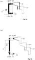
- FIGS. 5A to 5C exemplary sub-steps of an embodiment of the method are shown. This is a process in which two machining operations are performed during the pre-machining phase.
- the second editing process which is in Fig. 5B shown is optional.
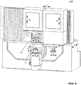
- Fig. 6 shows a perspective view of a grinding machine 100, in which the method of the invention can be used. However, the invention can also be used in other gear cutting machines 100.
- An embodiment of the method of the invention comprises the following steps, which are described with reference to FIGS FIGS. 5A to 5C to be discribed.
- FIGS. 5A to 5C was chosen a presentation format that was derived from the representations in the aforementioned book "bevel gears, fundamentals, applications”.
- the method may begin by performing a relative feed motion PA to bring a cup grinding wheel 10 (or other gear cutting tool 10) to an initial position AP1 relative to the bevel gear workpiece 11.
- This starting position AP1 is defined inter alia by a first rolling angle.
- the following is generally speaking of gear tools 10, even if in the figures by way of example a cup grinding wheel 10 is shown.
- the gear cutting tool 10 is rotationally driven about a tool spindle axis A1 of the gear cutting machine 100.
- the relative feed movement PA can take place using one or more axes of the gear cutting machine 100.
- the feed movement PA may be a linear movement or it may follow a curved path.
- the feed PA may also include multiple linear and / or curved movements.
- the feed movement PA is preferably a non-productive movement in all embodiments.
- the block arrow PA is therefore shown in white.
- a dip rolling process of a first machining operation 110 may begin to produce at least one tooth gap 13 in the material of the bevel gear workpiece 11 by grinding or milling.
- This immersion rolling process comprises at least the following sub-processes. By using the number words "first ..”, "second ..” etc., no chronological order should be specified. Rather, these numerals are used to simplify the naming of individual processes.
- first dipping process PB As part of a first dipping process PB, the penetration of the gear tool 10 into the material of the bevel gear workpiece 11 takes place.
- This is a productive first dipping process PB.
- the penetration begins at the starting position AP1 and takes place up to a first diving end position 1.TEP.
- the first dipping operation PB results from one or more relative movements of one or more axes of the gear cutting machine 100.
- the first dipping operation PB may be a linear movement or it may follow a curved path.
- the first dipping process PB can also comprise a plurality of linear and / or curved movements.
- a first rolling process WA follow in which the gear tool 10 and the bevel gear workpiece 11 perform relative movements with superimposed Wälzcardung ⁇ 2.
- Fig. 3 is a corresponding Wälzcardung ⁇ 2 shown by way of example.
- the rolling rotation ⁇ 2 refers to a rotational movement of the bevel gear workpiece 11 about the workpiece spindle axis B.
- the relative movements of the rolling operation WA with superimposed pitch rotation ⁇ 2 lead to a complex 3-dimensional movement of the gear tool 10 relative to the bevel gear workpiece 11.
- This complex sequence of movements is symbolized by the black arrow WA.
- a first rolling end position 1.WEP is achieved.
- the puff PC may be a linear motion or it may follow a curved path.
- the exchange movement PC can also comprise a plurality of linear and / or curved movements.
- the exchange movement PC may also result from one or more relative movements of one or more axes of the gear cutting machine 100.
- the puff PC may be a productive or non-productive movement in all embodiments.
- a relative plunge or puncturing movement PF may be performed to move the gear tool 10 relative to the bevel gear workpiece 11 from a second home position AP2 to another end plunge position 2.TEP Material to penetrate.
- this plunge or insertion movement PF may be a linear movement or it may follow a curved path. It can also include multiple linear and / or curved movements. The movement PF may also result from one or more relative movements of one or more axes of the gear cutting machine 100.
- a second rolling process WB follow in which the toothing tool 10 and the bevel gear workpiece 11 perform the relative movements of a rolling process with superimposed Wälzcardung ⁇ 3.
- the second rolling process WB is longer in the illustrated embodiment than the first rolling process WA, as indicated by the differently long block arrows WA and WB.
- the first rolling process WA can also be longer than the second rolling process WB.
- a relative exchange movement PG take place up to a second end position EP2.
- the exchange movement PG can be a linear movement in all embodiments or it can follow a curved path.
- the exchange movement PG can also comprise a plurality of linear and / or curved movements.
- the movement PG may also result from one or more relative movements of one or more axes of the gear cutting machine 100.
- the evacuation movement PG may be a productive or non-productive movement in all embodiments.
- the post-processing phase 112 includes a movement PH around the gear tool 10 relative to the bevel gear workpiece 11, for example, from a third starting position AP3 to deliver a fourth starting position AP4 outside the material.
- This third home position AP3 differs from the first home position AP1 by the roll angle. That is, the rolling process WC of the post-processing phase 112 starts from a different rolling angle than the rolling process WA.
- This movement PH may be a linear movement or it may follow a curved path. It can also include multiple linear and / or curved movements. The movement PH may also result from one or more relative movements of one or more axes of the gear cutting machine 100.
- a third rolling WC follow in which the toothing tool 10 and the bevel gear workpiece 11 perform relative movements with superimposed Wälzcardung ⁇ 4.
- the third rolling process WC is longer in the illustrated embodiment than the first rolling process WA (and as the second optional rolling process WB), as indicated by the differently long block arrows WA, WB and WC.
- a complete rolling of the corresponding tooth gap 13 takes place.
- the third rolling region may comprise an inlet region and / or an outlet region in all embodiments.
- the black block arrow WC at the beginning of Wälz (top in Fig. 5C ) and at the Wälzende (bottom in Fig. 5C ) each have a white area. This is to show that not the entire rolling process WC must be productive.
- the gear tool 10 can be located relative to the bevel gear workpiece 11 in each case in a different starting position.
- the gear tool is in the position of Fig. 5A in FIGS. 5B and 5C provided with the reference numeral 10 *.
- the gear tool is in the position of Fig. 5B in Fig. 5C provided with the reference numeral 10 **.
- This kind of Representation is purely schematic in nature and is intended to better understand.
- the steps are performed according to the steps Fig. 5C a pitch rotation of the bevel gear workpiece 11 and the method of Figures 5A and 5C or the Figures 5A . 5B and 5C Repeats after reaching the next starting position AP1 with the step PB.
- the first rolling operation WA can be performed in all embodiments e.g. even before reaching the first diving end position 1.TEP, just to give an example.
- the first rolling operation WA can be performed in all embodiments e.g. even before reaching the position 1.WEP be stopped, to give another example.
- the second rolling operation WB if present, can be performed in all embodiments e.g. even before reaching the second diving end position 2.TEP, just to name one example.
- the second rolling operation WB if present, can be performed in all embodiments e.g. be stopped before reaching position 2.WEP, to give another example.
- All embodiments comprise at least one relative feed movement (eg PA in Fig. 5A ) to place the gear tool 10 in a home position (eg, AP1 in FIG Fig. 5A ) relative to the bevel gear workpiece 11.
- This starting position is associated with a first Wälzwiegenwinkel.
- the gear tool 10 is rotationally driven about the tool spindle axis A1 of the grinding machine 100 (rotational speed ⁇ 1) in order to achieve the required cutting speed.
- the toothing tool 10 can also be continuously rotated (from constant speed or variable speed) from the start of the process to the end of the process in order to prevent multiple starting and deceleration.
- the relative movement may occur in all embodiments using one or more axes of the gear cutting machine 100.
- the relative movement may be a linear motion in all embodiments or they may follow a curved path.
- the relative movements may also include multiple linear and / or curved movements in all embodiments.
- the pre-machining phase may optionally provide a stepwise immersion in the material of the bevel gear workpiece 11 to reduce the wear on the gear tool 10. In this case, there is talk of a multi-stage pre-processing phase.
- the multi-stage pre-machining phase may also include a change in the rotational speed ⁇ 1 of the gear tool and / or a change in the speed of the relative movement (s) in order to reduce wear and increase the efficiency of the method.
- the multi-stage submersible rolling method of the pre-machining phase can be used separately for generating each tooth space 13 of the Bevel gear workpiece 11 are performed, wherein the bevel gear workpiece 11 each performs a pitch rotation about the workpiece spindle axis B of the gear cutting machine 100, before by re-executing the sub-processes of the multi-stage Vorbearbeitungsphase another tooth gap 13 of the bevel gear workpiece 11 is generated.
Abstract
Verfahren zum Verzahnen eines Kegelrad-Werkstücks (11), wobei eine Vorbearbeitungsphase die folgenden Schritte umfasst:- einen ersten Bearbeitungsvorgang, bei dem• eine erste relative Zustellbewegung durchgeführt wird, um das Verzahnungswerkzeug (10) in eine erste Ausgangsposition relativ zu dem Kegelrad-Werkstück (11) zu bringen,• das Verzahnungswerkzeug (10) relativ zum Kegelrad-Werkstück (11), ausgehend von der ersten Ausgangsposition bis zu einer ersten Endposition in Material des Kegelrad-Werkstücks (11) eindringt, und• bei dem das Verzahnungswerkzeug (10) und das Kegelrad-Werkstück (11) einen ersten Wälzvorgang in einem ersten Wälzbereich durchführen,und wobei eine Nachbearbeitungsphase die folgenden Schritte umfasst:- Durchführen eines weiteren Wälzvorgangs, um mit dem drehangetriebenen Verzahnungswerkzeug (10) oder mit einem anderen drehangetriebenen Verzahnungswerkzeug mindestens eine der Zahnlücken (13) an dem Kegelrad-Werkstück (11) nach zu bearbeiten, wobei im Rahmen dieses weiteren Wälzvorgangs eine Wälzdrehung in einem dritten (weiteren) Wälzbereich durchgeführt wird, der sich von dem ersten Wälzbereich unterscheidet.A method of intermeshing a bevel gear workpiece (11), wherein a pre-machining phase comprises the steps of: - a first machining operation in which a first relative feed motion is performed to move the gear tool (10) to a first home position relative to the bevel gear workpiece (11) to bring, • the gear tool (10) relative to the bevel gear workpiece (11), starting from the first initial position to a first end position in material of the bevel gear workpiece (11) penetrates, and • in which the gear tool (10 ) and the bevel gear workpiece (11) perform a first rolling operation in a first rolling range, and wherein a finishing phase comprises the following steps: - performing a further rolling operation to at least one of the. with the rotary driven toothing tool (10) or with another rotary driven toothing tool Tooth gaps (13) on the bevel gear workpiece (11) to edit, wob ei in the context of this further rolling a Wälzdrehung in a third (further) Wälzbereich is performed, which differs from the first Wälzbereich.
Description
Gegenstand der Erfindung ist ein Verfahren zum Verzahnen von Kegelrad-Werkstücken.The invention relates to a method for interlocking bevel gear workpieces.
Es gibt verschiedene Ansätze zum Verzahnen von Kegel- und Hypoidrädern. Dazu gehören zum Beispiel das Fräsen und Schleifen.There are different approaches to meshing conical and hypoid gears. These include, for example, milling and grinding.
Zusätzlich unterscheidet man Einzelteilverfahren und kontinuierlich teilende Verfahren. Bei einem Einzelteilverfahren werden die entsprechenden Verfahrensschritte mehrmals (entsprechend der Anzahl der Lücken) wiederholt. Beim kontinuierlichen Ansatz hingegen werden alle Zahnlücken in einem Durchlauf bearbeitet.In addition, a distinction is made between single part methods and continuous dividing methods. In a single part method, the corresponding process steps are repeated several times (corresponding to the number of gaps). In the continuous approach, however, all gullets are processed in one pass.
Beim Wälzen einer Verzahnung muss ein bestimmter Wälzbereich zur Erzeugung des Profils der Zahnflanken durchlaufen (durchgewälzt) werden, wobei die Richtung der Wälzbewegung zwischen Verzahnungswerkzeug und Werkstück von der Zehe zur Ferse des Werkstücks oder von der Ferse zur Zehe gewählt werden kann. Dieser Wälzbereich wird durch Anfangswinkel und Endwinkel definiert und der Anfangswinkel dieses Bereiches wird hier als Anfangsprofilwälzwinkel und der Endwinkel als Endprofilwälzwinkel bezeichnet. Der Anfangsprofilwälzwinkel und der Endprofilwälzwinkel definieren den Wälzbereich, in dem durch das Verzahnungswerkzeug gerade noch Punkte des Zahnflankenprofils generiert werden. Der Bereich zwischen diesen Profilwälzwinkeln (Wälzstellungen) kann als Profilwälzbereich bezeichnet werden. Es gibt einen Profilwälzwinkel für die Zehe (Profilwälzwinkel-Zehe genannt) und einen Profilwälzwinkel für die Ferse (Profilwälzwinkel-Ferse genannt) des Werkstücks.When rolling a toothing a certain rolling range for generating the profile of the tooth flanks must be traversed (rolled), wherein the direction of the rolling movement between the toothing tool and the workpiece from the toe to the heel of the workpiece or from the heel to the toe can be selected. This rolling range is defined by start angle and end angle, and the start angle of this range is referred to herein as the initial profile rolling angle and the end angle is referred to as the end profile rolling angle. The Anfangssprofilwälzwinkel and Endprofilwälzwinkel define the Wälzbereich, in which by the gear tool just points of the Tooth flank profiles are generated. The area between these profile rolling angles (Wälzstellungen) can be referred to as a profile rolling area. There is a profile rolling angle for the toe (called profile rolling angle toe) and a profile rolling angle for the heel (called profile rolling angle heel) of the workpiece.
Der jeweilige Profilwälzbereich ergibt sich aus den geometrischen Eigenschaften des zu verzahnenden Kegelrades und aus dem Prozess, der zum Verzahnen eingesetzt wird. D.h. der Profilwälzbereich ist eine Größe, die rechnerisch z.B. im Rahmen der Auslegung ermittelt werden kann. Der Profilwälzbereich ist somit eine feste Prozessgröße des Verzahnungsprozesses des jeweiligen Kegelrades. Je nach Prozess, der zum Verzahnen von Kegel- und Hypoidrädern verwendet wird, kann gemäß Stand der Technik der Wälzweg sogar etwas länger sein, um einen kleinen Sicherheitsabstand vorzugeben.The respective profile rolling range results from the geometric properties of the bevel gear to be toothed and from the process used for gear cutting. That the profile rolling area is a size calculated by e.g. can be determined in the context of the interpretation. The profile rolling area is thus a fixed process variable of the toothing process of the respective bevel gear. Depending on the process used to mesh bevel and hypoid gears, according to the prior art, the pitch may even be slightly longer to provide a small margin of safety.
Es gibt Punkte oder Bereiche in einer Zahnlücke, die nicht auf dem endgültigen Zahnprofil liegen und die nicht durch eine reine Wälzbewegung innerhalb des Profilwälzbereichs entfernt werden. Ihre Lage ist vom Wälzanfang und der Wälzrichtung abhängig. Um in diesen Bereichen Material des Werkstücks zu entfernen, wird entweder eine Tauchbewegung gewählt, bei der Material am Werkstück entfernt wird (Tauch-Wälzen genannt) oder es wird ein größerer Wälzbereich gewählt. Die Wälzwinkel, die diesen größeren Bereich begrenzen, werden durch einen Einwälzwinkel und einen Profilwälzwinkel definiert. Es handelt sich bei dem Einwälzwinkel um jenen Wälzwinkel, bei dem das Werkzeug bei einer reinen Wälzbewegung erstmalig beginnt Material am Werkstück zu entfernen. Diese erstmalige Berührung erfolgt am Kopfkegel des Werkstücks und je nach Wälzrichtung (beim Wälzen von der Zehe zur Ferse) an der Zehe des Werkstücks (Einwälzwinkel-Zehe) oder (beim Wälzen von der Ferse zur Zehe) an der Ferse des Werkstücks (Einwälzwinkel-Ferse).There are points or areas in a tooth space that are not on the final tooth profile and that are not removed by a pure rolling motion within the profile rolling area. Their position depends on the beginning of rolling and the rolling direction. In order to remove material of the workpiece in these areas, either a submerged motion is selected in which material is removed from the workpiece (called dive rolling) or a larger rolling range is selected. The rolling angles, which limit this larger area, are defined by a Einwälzwinkel and a Profilwälzwinkel. The entry angle is the rolling angle at which the tool first begins to remove material from the workpiece during a pure rolling movement. This initial contact occurs at the head of the workpiece and depending on the rolling direction (when rolling from toe to heel) on the toe of the workpiece (Einwälzwinkel toe) or (when rolling from heel to toe) at the heel of the workpiece (Einwälzwinkel heel ).
Ein weiterer Punkt auf dem Wälzweg oder im Wälzbereich ist die sogenannte Wälzmitte. Das ist per Definitionem der Wälzwinkel, bei dem der Auslegungspunkt der Verzahnung erzeugt wird. Er muss nicht exakt in der Mitte des Wälzwegs zwischen Profilwälzwinkel-Zehe und Profilwälzwinkel-Ferse liegen.Another point on the Wälzweg or Wälzbereich is the so-called Wälzmitte. This is by definition the rolling angle at which the design point of the toothing is generated. It does not have to lie exactly in the middle of the Wälzwegs between profile rolling angle toe and Profilwälzwinkel heel.
Unter anderem werden die folgenden Prozesse zum Verzahnen von Kegel- und Hypoidrädern verwendet:Among others, the following processes are used for meshing bevel and hypoid gears:
Einwälzen: Hierbei erfolgen keine Tauchbewegungen, bei denen Material abgenommen wird. Das Verzahnen erfolgt nur durch Wälzen. Es handelt sich somit um einen reinen Wälzprozess. Das Verzahnungswerkzeug wird im Eilgang außerhalb des Eingriffs mit dem Werkstück auf volle Tiefe gefahren. Außerhalb des Eingriffs bedeutet hier, dass eine Wälzstellung am Einwälzwinkel-Zehe (beim Wälzen von der Zehe zur Ferse) bzw. am Einwälzwinkel-Ferse (beim Wälzen von der Ferse zur Zehe) plus eines kleinen Sicherheitsabstands auf dem Wälzweg angefahren wird. Von hier beginnt die Wälzbewegung, d.h. der jeweilige Einwälzwinkel (plus ein Sicherheitsabstand) definiert den Wälzanfang. Die Wälzbewegung erfolgt dann bis zum entsprechenden Profilwälzwinkel-Ferse (beim Wälzen von der Zehe zur Ferse) bzw. bis zum entsprechenden Profilwälzwinkel-Zehe (beim Wälzen von der Ferse zur Zehe). Die Geschwindigkeit der Wälzbewegung kann bei diesem Wälzprozess über den Wälzweg konstant oder veränderlich sein. Am Wälzende (z.B. beim Profilwälzwinkel-Ferse) wird das Verzahnungswerkzeug aus der Lücke herausgefahren. Falls dieser Wälzprozess als Einzelteilverfahren ausgeführt wird, erfolgt nun die Teilbewegung und der beschriebene Vorgang wiederholt sich Lücke-für-Lücke. Rolling in: There are no immersion movements during which material is removed. The gearing is done only by rolling. It is therefore a pure rolling process. The gear tool is moved at full speed out of engagement with the workpiece to full depth. Out of engagement here means that a rolling position is approached at Einwälzwinkel toe (when rolling from toe to heel) or Einwälzwinkel heel (when rolling from heel to toe) plus a small safety distance on the Wälzweg. The rolling motion starts from here, ie the respective entry angle (plus a safety distance) defines the start of rolling. The rolling motion then takes place up to the corresponding profile rolling angle heel (when rolling from toe to heel) or to the corresponding profile rolling angle toe (when rolling from heel to toe). The speed of the rolling motion can be constant or variable in this Wälzprozess on the Wälzweg. At Wälzende (eg the profile rolling angle heel) the gear tool is moved out of the gap. If this rolling process is carried out as a single-part method, the partial movement now takes place and the process described is repeated gap-by-gap.
Einstechwälzen: Das Einstechwälzen ist ein Tauch-Wälzprozess. Hier wird am Wälzanfang eingestochen oder eingetaucht. Je nach Wälzrichtung erfolgt dieses Einstechen am Profilwälzwinkel-Zehe (beim Wälzen von der Zehe zur Ferse) oder am Profilwälzwinkel-Ferse (beim Wälzen von der Ferse zur Zehe). Es wird mit einem Sicherheitsabstand in Tauchrichtung startend in einer Einstechbewegung in das Werkstück an der Zehe oder an der Ferse bis auf volle Zahntiefe eingestochen (auch Eintauchen genannt). Ist die volle Zahntiefe erreicht, stoppt die Einstechbewegung und es folgt die Wälzbewegung. Wälzende ist beim Einstechwälzen der jeweilige Profilwälzwinkel (Profilwälzwinkel-Ferse für die Wälzrichtung von der Zehe zur Ferse oder Profilwälzwinkel-Zehe für die Wälzrichtung von der Ferse zur Zehe). Die Geschwindigkeit der Wälzbewegung kann über den Wälzweg konstant oder veränderlich sein. Am Wälzende wird das Verzahnungswerkzeug aus der Lücke herausgefahren. Falls dieser Tauch-Wälzprozess als Einzelteilverfahren ausgeführt wird, erfolgt nun die Teilbewegung und der Vorgang wiederholt sich Lücke-für-Lücke. Grooving: Grooving is a dip rolling process. Here, at the beginning of the rolling process, it is inserted or dipped. Depending on the direction of rolling, this piercing takes place at the profile rolling angle toe (when rolling from the toe to the heel) or at the profile rolling angle heel (when rolling from the heel to the toe). It is inserted with a safety distance in the diving direction starting in a penetration into the workpiece at the toe or heel to full tooth depth (also called dipping). When the full tooth depth is reached, the piercing movement stops and the rolling motion follows. Wälzende is when Einstechwälzen the respective Profilwälzwinkel (Profilwälzwinkel heel for the rolling direction of the toe to the heel or Profilwälzwinkel toe for the rolling direction of the heel to toe). The speed of the rolling motion can be constant or variable over the rolling path. At Wälzende the gear tool is moved out of the gap. If this diving rolling process is executed as a single part method, now the partial movement takes place and the process repeats gap-by-gap.
Einstechdoppelwälzen: Das Einstechdoppelwälzen ist auch ein Tauch-Wälzprozess. Auch hier wird von einer Wälzstellung außerhalb des Werkstücks startend in das Werkstück eingetaucht und Material entfernt. Hierbei liegt der Wälzanfang zwischen dem Profilwälzwinkel-Zehe und dem Profilwälzwinkel-Ferse, jedoch nicht genau auf diesen. Häufig wird die Wälzmitte zum Eintauchen (auch Einstechen genannt) gewählt. Das Eintauchen kann bis auf volle Zahntiefe erfolgen oder es wird ein geringes Tiefenaufmaß stehen gelassen, d.h. das Eintauchen wird in der Position der vollen Zahntiefe minus einem Tiefenaufmaß gestoppt. Von diesem Punkt erfolgt nun die Wälzbewegung in Richtung Zehe bis zum Profilwälzwinkel-Zehe oder in Richtung Ferse bis zum Profilwälzwinkel-Ferse. Ist dieser Punkt erreicht, erfolgt, wenn ein Tiefenaufmaß stehen gelassen wurde, die Zustellung auf volle Zahntiefe, und dann eine Wälzbewegung in die andere Richtung bis zum jeweils anderen Profilwälzwinkel. Die Geschwindigkeit der Wälzbewegung kann über den Wälzweg konstant oder veränderlich sein. Am Wälzende wird das Verzahnungswerkzeug aus der Lücke herausgefahren. Falls dieser Tauch-Wälzprozess als Einzelteilverfahren ausgeführt wird, erfolgt nun die Teilbewegung und der Vorgang wiederholt sich Lücke-für-Lücke. Einstechdoppelwälzen: The Einstechdooppeltwälzen is also a dip-rolling process. Again, starting from a Wälzstellung outside the workpiece is immersed in the workpiece and material removed. Here, the Wälzanfang between the Profilwälzwinkel toe and the Profilwälzwinkel heel, but not exactly on this. Frequently, the roller center is chosen for immersion (also called grooving). The immersion can be done down to full tooth depth or a slight depth allowance is left, ie the immersion is stopped in the position of the full tooth depth minus a depth allowance. From this point, the rolling motion now takes place in the direction of the toe up to the profile rolling angle toe or in the direction of the heel up to the profile rolling angle heel. When this point is reached, if a depth allowance has been left, the delivery to full tooth depth, and then a rolling movement in the other direction to the other profile rolling angle. The speed of the rolling motion can be constant or variable over the rolling path. At Wälzende the gear tool is moved out of the gap. If this immersion rolling process is performed as a single part method, the partial movement now takes place and the process repeats gap-by-gap.
Doppelwälzen: Bei diesem Prozess erfolgen keine Tauchbewegungen bei denen Material abgenommen wird. Das Verzahnen erfolgt nur durch Wälzen. Es handelt sich somit um einen reinen Wälzprozess. Das Verzahnungswerkzeug wird im Eilgang außerhalb des Eingriffs mit dem Werkstück auf volle Tiefe minus einem Tiefenaufmaß gefahren. Außerhalb des Eingriffs bedeutet hier, dass eine Wälzstellung am Einwälzwinkel-Zehe (beim Wälzen von der Zehe zur Ferse) bzw. am Einwälzwinkel-Ferse (beim Wälzen von der Ferse zur Zehe) plus eines kleinen Sicherheitsabstandes auf dem Wälzweg angefahren wird. Von hier beginnt die Wälzbewegung, d.h. der jeweilige Einwälzwinkel (zuzüglich des Sicherheitsabstandes) definiert den Wälzanfang. Die Wälzbewegung erfolgt dann bis zum entsprechende Profilwälzwinkel-Ferse (beim Wälzen von der Zehe zur Ferse) bzw. bis zum entsprechende Profilwälzwinkel-Zehe (beim Wälzen von der Ferse zur Zehe). Ist der entsprechende Profilwälzwinkel erreicht, so erfolgt eine Tauchzustellung um das Tiefenaufmaß und anschließend das Rückwälzen bis zum jeweils anderen Profilwälzwinkel. Bei diesem Prozess wird die erste Wälzbewegung meist als Schruppwälzen und die zweite Wälzbewegung als Schlichtwälzen durchgeführt. Die Geschwindigkeit der Wälzbewegung kann über den Wälzweg konstant oder veränderlich sein. Am Wälzende wird das Verzahnungswerkzeug aus der Lücke herausgefahren. Falls dieser Wälzprozess als Einzelteilverfahren ausgeführt wird, erfolgt nun die Teilbewegung und der Vorgang wiederholt sich Lücke-für-Lücke.Double rolling : In this process, no immersion movements take place in which material is removed. The gearing is done only by rolling. It is therefore a pure rolling process. The gear tool is moved in rapid traverse out of engagement with the workpiece to full depth minus a Tiefenaufmaß. Out of engagement here means that a rolling position at Einwälzwinkel toe (when rolling from toe to heel) or at Einwälzwinkel heel (when rolling from heel to toe) plus a small safety distance on the Wälzweg is approached. From here, the rolling motion begins, ie the respective entry angle (plus the safety distance) defines the start of rolling. The rolling movement then takes place up to the corresponding profile rolling angle heel (when rolling from the toe to the heel) or until the corresponding profile rolling angle toe (when rolling from the heel to the toe). Is the corresponding one Profilwälzwinkel reached, it is a Tauchzustellung to the Tiefenaufmaß and then the rolling back to the other profile rolling angle. In this process, the first rolling motion is usually carried out as roughing and the second rolling as sizing. The speed of the rolling motion can be constant or variable over the rolling path. At Wälzende the gear tool is moved out of the gap. If this rolling process is carried out as a single-part method, the partial movement now takes place and the process repeats gap-by-gap.
Tauchen: Hierbei handelt es sich um eine reine Tauchbearbeitung und es erfolgt kein Wälzen. Dieser Prozess kann nur für entsprechend ausgelegte Tellerräder verwendet werden. Der Tauchprozess startet mit einem Sicherheitsabstand. Von hier aus erfolgt die Tauchbewegung. Diese kann mit konstanter oder veränderlicher Tauchgeschwindigkeit oder in Stufen erfolgen. Auch ein anschließendes Verweilen auf voller Zahntiefe kann vorgesehen werden. Hierbei kann auch ein Freischneiden durchgeführt werden. Anschließend wird das Verzahnungswerkzeug aus der Lücke herausgefahren. Falls dieser Tauchprozess als Einzelteilverfahren ausgeführt wird, erfolgt nun die Teilbewegung und der Vorgang wiederholt sich Lücke-für-Lücke. Diving: This is a pure dipping and there is no rolling. This process can only be used for appropriately designed crown wheels. The dipping process starts with a safety distance. From here the diving movement takes place. This can be done with constant or variable diving speed or in stages. A subsequent stay on full tooth depth can be provided. Here also a free cutting can be done. Subsequently, the gear tool is moved out of the gap. If this dipping process is carried out as a single-part method, the partial movement now takes place and the process repeats gap-by-gap.
Bei den hier beschriebenen Prozessen ist es so, dass alle Wälzprozesse als Wälzende einen Profilwälzwinkel haben. Auch sind die Wälzwege, wenn mehrere Umläufe erfolgen (bspw. Eintauchen an der Zehe mit einem Profilwälzwinkel-Zehe) mit Tiefenaufmass, Wälzen bis zum Profilwälzwinkel-Ferse, Tiefenzustellung an der Ferse (nicht auf die volle Zahntiefe), Wälzen bis zum Profilwälzwinkel-Zehe, Tiefenzustellung auf volle Zahntiefe, Wälzen bis zum Profilwälzwinkel-Ferse, Ausfahren aus der Zahnlücke) immer gleich lang.In the processes described here, it is the case that all rolling processes as rolling ends have a profile rolling angle. The Wälzwege are when several rounds done (for example, immersion on the toe with a Profilwälzwinkel toe) with Tiefenaufmass, rolling up to Profilwälzwinkel heel, Tiefenzustellung on the heel (not on the full tooth depth), rolling up to Profilwälzwinkel toe , Depth infeed to full tooth depth, rolling up to the profile rolling angle heel, extension from the tooth gap) always the same length.
Der Wälzweg definiert sich somit stets mindestens aus der Differenz des Profilwälzwinkel-Zehe und des Profilwälzwinkel-Ferse. Je nach Prozess, der zum Verzahnen von Kegel- und Hypoidrädern verwendet wird, kann der Wälzweg bei Verfahren des Standes der Technik sogar länger sein.The rolling path thus always defines at least the difference between the profile rolling angle toe and the profile rolling angle heel. Depending on the process used to mesh bevel and hypoid gears, the pitch may even be longer in prior art methods.
Anhand der
Bei dem hier gezeigten Prozess 1 wird die Topfschleifscheibe 10 relativ zum Kegelrad-Werkstück 11 zugestellt, um eine Ausgangsposition AP zu erreichen. Die entsprechende Zustellbewegung ist in
Nun folgt, wie in
Nun kann das Kegelrad-Werkstück eine Teilungsdrehung durchführen und die Topfschleifscheibe 10 wird zur Ausgangsposition AP bewegt. Dann wiederholt sich der in den
Die erwähnten Wälzvorgänge umfassen jeweils eine Überlagerung von Relativbewegungen. Details hierzu sind z.B. den Seiten 76-77 und der Abbildung 3.5 des Buches "
Die Abbildung 3.5 des genannten Buches ist in den Zeichnungen als
Die genannten Bewegungen finden im 3-dimensionalen Raum statt. Die schematischen Darstellungen, wie sie in
Um diesen Vorgang 3-dimensional illustrieren zu können, ist in
Der Verschleiß an der Topfschleifscheibe 10 ist jedoch beim zuvor beschriebenen Prozess 1 recht groß und die Topfschleifscheibe 10 muss häufig abgerichtet werden. Vor allem hat sich gezeigt, dass der Verschleiß im Bereich des Profilkopfes 12 (siehe
Es ist eine Aufgabe der Erfindung ein Verfahren bereit zu stellen, das geeignet ist die beispielhaft beschriebenen Wälzverfahren des Standes der Technik produktiver zu machen und den Verschleiß an der Topfschleifscheibe bzw. am Fräswerkzeug zu reduzieren.It is an object of the invention to provide a method which is capable of making the rolling processes of the prior art described by way of example more productive and of reducing the wear on the cup grinding wheel or on the milling tool.
Gemäß Erfindung wird ein Verfahren vorgeschlagen, das speziell zum Verzahnen von Kegelrad-Werkstücken in einer Verzahnungsmaschine ausgelegt ist, wobei das Verfahren ein Vorbearbeitungsphase (z.B. als Schruppbearbeitung) und eine nachfolgende Nachbearbeitungsphase (z.B. als Schlichtbearbeitung) umfasst. Die Vorbearbeitungsphase und die Nachbearbeitungsphase erfolgen beide in derselben Aufspannung des Kegelrad-Werkstücks.According to the invention, a method is proposed which is especially suitable for the toothing of bevel gear workpieces in a gear cutting machine is designed, the method comprises a pre-processing phase (eg, as roughing) and a subsequent post-processing phase (eg, as finishing). The pre-processing phase and the post-processing phase are both carried out in the same clamping of the bevel gear workpiece.
Die Vorbearbeitungsphase umfasst gemäß Erfindung stets mindestens ein einstufiges (Tauch-)Wälzverfahren. Die Vorbearbeitungsphase kann gemäß Erfindung aber auch ein mehrstufiges (Tauch-)Wälzverfahren umfassen. Dieses ein- oder mehrstufige (Tauch-)Wälzverfahren wird durchgeführt, um durch Bearbeitung mit einem Verzahnungswerkzeug mindestens eine Zahnlücke an dem Kegelrad-Werkstück zu bearbeiten. Das Wälzverfahren der Vorbearbeitungsphase umfasst bei allen Ausführungsformen
- mindestens einen ersten Bearbeitungsvorgang, bei dem
- eine erste relative Zustellbewegung durchgeführt wird, um das Verzahnungswerkzeug in eine erste Ausgangsposition relativ zu dem Kegelrad-Werkstück zu bringen,
- das Verzahnungswerkzeug um eine Werkzeugspindelachse der Verzahnungsmaschine drehangetrieben wird,
- das Verzahnungswerkzeug relativ zum Kegelrad-Werkstück, ausgehend von der ersten Ausgangsposition bis zu einer ersten Endposition in Material des Kegelrad-Werkstücks eindringt, und
- bei dem das Verzahnungswerkzeug und das Kegelrad-Werkstück einen ersten Wälzvorgang in einem ersten Wälzbereich durchführen.
- at least one first processing operation in which
- a first relative feed movement is performed to bring the gear tool to a first home position relative to the bevel gear workpiece,
- the gear tool is rotationally driven about a tool spindle axis of the gear cutting machine,
- the gear tool penetrates relative to the bevel gear workpiece, starting from the first starting position to a first end position in the material of the bevel gear workpiece, and
- wherein the gear tool and the bevel gear workpiece perform a first rolling operation in a first rolling range.
Falls die Vorbearbeitungsphase ein mehrstufiges (Tauch-) Wälzverfahren umfasst, dann kann sie zusätzlich zu dem ersten Bearbeitungsvorgang umfassen:
- einen zweiten Bearbeitungsvorgang, bei dem
- das Verzahnungswerkzeug (weiter) um die Werkzeugspindelachse der Verzahnungsmaschine drehangetrieben wird,
- das Verzahnungswerkzeug relativ zum Kegelrad-Werkstück, ausgehend von einer zweiten Ausgangsposition bis zu einer zweiten Endposition in das Material des Kegelrad-Werkstücks eindringt, und
- bei dem das Verzahnungswerkzeug und das Kegelrad-Werkstück einen zweiten Wälzvorgang in einem zweiten Wälzbereich durchführt,
- a second processing operation in which
- the gear tool is (further) rotated about the tool spindle axis of the gear cutting machine,
- the gear tool relative to the bevel gear workpiece, from a second starting position to a second end position penetrates into the material of the bevel gear workpiece, and
- wherein the gear tool and the bevel gear workpiece perform a second rolling operation in a second rolling area,
Die Nachbearbeitungsphase umfasst bei allen Ausführungsformen stets mindestens die folgenden Schritte:
- Durchführen eines weiteren Wälzvorgangs ausgehend von einer dritten (weiteren) Ausgangsposition, um mit einem Verzahnungswerkzeug mindestens eine der Zahnlücken an dem Kegelrad-Werkstück nach zu bearbeiten, wobei im Rahmen dieses weiteren Wälzvorgangs eine Wälzdrehung in einem dritten Wälzbereich durchgeführt wird wobei die erste Ausgangsposition des ersten Bearbeitungsvorgangs einen anderen Wälzwiegenwinkel aufweist als die dritte (weitere) Ausgangsposition der Nachbearbeitungsphase.
- Performing a further rolling operation starting from a third (further) starting position in order to machine with a gear tool at least one of the tooth gaps on the bevel gear workpiece, wherein in this further rolling a Wälzdrehung in a third Wälzbereich is performed wherein the first starting position of the first Machining process has a different rolling angle than the third (further) starting position of the post-processing phase.
D.h., es wird vor der Nachbearbeitungsphase ein anderer Wälzwiegenwinkel eingestellt, als zu Beginn des ersten Bearbeitungsvorgangs.That is, a different bevel angle is set before the post-processing phase than at the beginning of the first processing operation.
Der dritte Wälzbereich kann bei mindestens einem Teil der Ausführungsformen einen Einlaufbereich und/oder einen Auslaufbereich umfassen.The third rolling region may include an inlet region and / or an outlet region in at least a portion of the embodiments.
Das Verzahnen von Kegelrad-Werkstücken kann gemäß Erfindung das Fräsen von Verzahnungen sowie das Schleifen von Verzahnungen an einem Kegelrad-Werkstück in einer als Verzahnungsmaschine dienenden Fräs- oder Schleifmaschine umfassen.The gearing of bevel gear workpieces according to the invention may include the milling of gears as well as the grinding of gears on a bevel gear workpiece in a milling or grinding machine serving as a gear cutting machine.
Vorzugsweise dient bei allen Ausführungsformen die Vorbearbeitungsphase zum Vorverzahnen oder Schruppen von Zahnlücken.In all embodiments, the pre-machining phase preferably serves for pre-toothing or roughing tooth spaces.
Das Vorverzahnen oder Schruppen kann z.B. bei allen Ausführungsformen mit einem Fräswerkzeug (z.B. mit einem Stabmesserkopf) erfolgen.The pre-toothing or roughing may e.g. in all embodiments with a milling tool (e.g., a bar cutter head).
Vorzugsweise dient bei allen Ausführungsformen die Nachbearbeitungsphase zum Nachbearbeiten oder Schlichten von Zahnlücken, die zuvor vorverzahnt oder geschruppt wurden.Preferably, in all embodiments, the post-processing phase is used for reworking or finishing tooth spaces that have been previously toothed or scrubbed.
Das Nachbearbeiten oder Schlichten kann z.B. bei allen Ausführungsformen mit einem Schleifwerkzeug (z.B. mit einer Topfschleifscheibe) erfolgen.Post-processing or sizing may e.g. in all embodiments, with a grinding tool (e.g., a cup grinding wheel).
Vorzugsweise kommt bei allen Ausführungsformen ein kombiniertes Wälzverfahren zum Einsatz, bei dem im Rahmen einer Vorbearbeitungsphase (oder Vorverzahnungsphase) die Zahnlücken des Kegelrad-Werkstücks nicht vollständig durchgewälzt werden. Im Rahmen der Nachbearbeitungsphase wird das Kegelrad-Werkstück jedoch vollständig durchgewälzt.In all embodiments, a combined rolling method is preferably used in which the tooth gaps of the bevel gear workpiece are not completely circulated during a pre-machining phase (or pre-toothing phase). During the post-processing phase, however, the bevel gear workpiece is completely rolled through.
Vorzugsweise wird bei allen Ausführungsformen zwischen der Vorbearbeitungsphase (oder Vorverzahnungsphase) und der Nachbearbeitungsphase ein Material-Aufmass stehen gelassen, das dann in der Nachbearbeitungsphase abgetragen wird. Bei dem Material-Aufmass kann es sich um ein Tiefenaufmass und/oder um ein Flankenaufmass handeln.Preferably, in all embodiments, between the pre-processing phase (or pre-toothing phase) and the post-processing phase, a material allowance is left, which is then removed in the post-processing phase. The material allowance can be a depth allowance and / or a flank allowance.
Vorzugsweise umfasst die Vorbearbeitungsphase bei allen Ausführungsformen ein mehrstufiges (Tauch-)Wälzverfahren mit mindestens zwei unterschiedlichen Bearbeitungsvorgängen.Preferably, the pre-processing phase in all embodiments comprises a multi-stage (dip) rolling process with at least two different processing operations.
Jeder Bearbeitungsvorgang der Vorbearbeitungsphase umfasst eine Relativbewegung, die dazu dient das Verzahnungswerkzeug in das Kegelrad-Werkstück einzutauchen oder einzustechen. D.h. es wird bei dieser Relativbewegung Material an dem Kegelrad-Werkstück abgetragen.Each machining operation of the pre-machining phase comprises a relative movement which serves to dip or stab the gear tool into the bevel gear workpiece. That In this relative movement, material is removed from the bevel gear workpiece.
Das Eintauchen oder Einstechen erfolgt vorzugsweise bei allen Ausführungsformen so, dass die Tauchendposition im Material des Kegelrad-Werkstücks liegt. D.h. das Verzahnungswerkzeug bewegt sich in das Material des Kegelrad-Werkstücks hinein.The dipping or piercing is preferably carried out in all embodiments so that the Tauchendposition is located in the material of the bevel gear workpiece. That is, the gear tool moves into the material of the bevel gear workpiece.
Jeder Bearbeitungsvorgang der Vorbearbeitungsphase umfasst eine Wälzdrehung, die ein Drehen des Kegelrad-Werkstücks relativ zum Verzahnungswerkzeug innerhalb eines Wälzbereichs umfasst.Each pre-machining phase machining operation includes a rolling rotation that includes rotating the bevel gear workpiece relative to the gear tool within a rolling zone.
Die Wälzdrehung eines ersten Bearbeitungsvorgangs erfolgt bei allen Ausführungsformen zum Beispiel in einem ersten Wälzbereich, wohingegen die Wälzdrehung eines zweiten Bearbeitungsvorgangs, falls ein solcher vorgesehen ist, in einem zweiten Wälzbereich erfolgt. Der erste Wälzbereich unterscheidet sich bei allen Ausführungsformen von dem zweiten Wälzbereich. Entweder ist der erste Wälzbereich kürzer als der zweite Wälzbereich, oder der erste Wälzbereich ist länger als der zweite Wälzbereich. Die Begriffe "kürzer" oder "länger" beziehen sich auf einen Winkelbereich oder auf eine Strecke, die durchwälzt wird.The Wälzdrehung a first machining operation is carried out in all embodiments, for example, in a first Wälzbereich, whereas the Wälzdrehung a second machining operation, if one is provided, takes place in a second Wälzbereich. The first rolling region differs from the second rolling region in all embodiments. Either the first rolling area is shorter than the second rolling area, or the first rolling area is longer than the second rolling area. The terms "shorter" or "longer" refer to an angular range or to a range that is being translated.
Die Vorbearbeitungsphase kann bei allen Ausführungsformen der Erfindung zwei unterschiedliche Wälzvorgänge umfassen. Als unterschiedliche Wälzvorgänge werden im vorliegenden Zusammenhang Wälzvorgänge bezeichnet,
- die sich durch ihre Ausgangspositionen und/oder Endpositionen unterscheiden, und/oder
- bei denen die Wälzvorgänge unterschiedlich lang sind (z.B. in Winkelgraden des Wälzwiegenwinkels gemessen), und/oder
- die mit unterschiedlichen Tiefenzustellungen des Verzahnungswerkzeugs (z.B. der Topfschleifscheibe oder der Messerkopfes) relativ zum Kegelrad-Werkstück durchgeführt werden, und/oder
- die sich durch ihre Ausgangspositionen und ihre Wälzgeschwindigkeiten oder durch ihre Endpositionen und ihre Wälzgeschwindigkeiten unterscheiden, und/oder
- die nicht, wie dies im Stand der Technik üblich ist, komplett vom Wälzanfang (am Profilwälzwinkel-Zehe oder Profilwälzwinkel-Ferse) bis zum Wälzende (am Profilwälzwinkel-Ferse oder am Profilwälzwinkel-Zehe) durchwälzen. D.h. bei dem/den Wälzvorgängen der Vorbearbeitungsphase werden weder der Profilwälzwinkel-Zehe noch der Profilwälzwinkel-Ferse erreicht.
- which differ by their starting positions and / or end positions, and / or
- in which the rolling processes are of different lengths (eg measured in degrees of rolling angle), and / or
- which are performed with different depth of supply of the gear tool (eg the cup grinding wheel or the cutter head) relative to the bevel gear workpiece, and / or
- which differ by their starting positions and their rolling speeds or by their end positions and their rolling speeds, and / or
- not, as is common in the prior art, completely from the Wälzanfang (at Profilwälzwinkel toe or Profilwälzwinkel heel) to Wälzende (on Profilwälzwinkel heel or on Profilwälzwinkel toe) by rolling. Ie at the rolling process (s) of the pre-machining phase neither the profile rolling angle toe nor the profile rolling angle heel are achieved.
Die Nachbearbeitungsphase umfasst bei allen Ausführungsformen einen Wälzvorgang, bei dem der Profilwälzwinkel-Zehe und der Profilwälzwinkel-Ferse erreicht werden. D.h. der dritte Wälzbereich kann sich bei mindestens einem Teil der Ausführungsformen vom Profilwälzwinkel-Zehe bis zum Profilwälzwinkel-Ferse oder umgekehrt erstrecken.In all embodiments, the post-processing phase includes a rolling process in which the profile rolling angle toe and the profile rolling angle heel are achieved. That the third rolling region may extend from the profile rolling angle toe to the profile rolling angle heel or vice versa in at least a portion of the embodiments.
Falls der dritte Wälzbereich einen Einlaufbereich und/oder einen Auslaufbereich umfasst, so kann sich der dritte Wälzbereich um ein kleines Stück über den Profilwälzwinkel-Zehe oder den Profilwälzwinkel-Ferse hinaus erstrecken.If the third rolling region comprises an inlet region and / or an outlet region, then the third rolling region may extend a little beyond the profile rolling angle toe or the profile rolling angle heel.
Durch die Erfindung wird das Verzahnen wirtschaftlicher gemacht.The invention makes gearing more economical.
Ausserdem ergibt sich durch die Erfindung ein Standzeitgewinn am Werkzeug.In addition, the invention results in a gain in tool life.
Vorzugsweise geht es hier um das Schruppen gewälzter Zahnlücken und das anschliessende Schlichten gewälzter Zahnlücken.Preferably, this is the roughing of rolled tooth gaps and the subsequent finishing of rolled tooth spaces.
Die Vorbearbeitungsphase der Erfindung kann zum Fräsen oder Schleifen von Zahnlücken am vollen Material (d.h. am nicht-vorverzahnten Material) des Kegelrad-Werkstücks vorgenommen werden.The pre-machining phase of the invention may be performed to mill or tooth gaps on the solid material (i.e., non-pre-toothed material) of the bevel gear workpiece.
Die Nachbearbeitungsphase der Erfindung wird hingegen an den vorverzahnten Zahnlücken des Kegelrad-Werkstücks vorgenommen.The post-processing phase of the invention, however, is carried out on the pre-toothed tooth gaps of the bevel gear workpiece.
Gemäß Erfindung kann bei allen Ausführungsformen das Aufteilen des Wälzens der Vorbearbeitungsphase in zwei oder mehr als zwei Wälzvorgänge dazu genutzt werden, um im Rahmen eines ersten Wälzvorganges die (dynamische) Belastung des Verzahnungswerkzeugs (z.B. der Topfschleifscheibe oder des Stabmesserkopfes) zu reduzieren und um im Rahmen eines zweiten Wälzvorganges nahezu die endgültige Flankengeometrie am Kegelrad-Werkstück bereitzustellen. Die endgültige Flankengeometrie wird dann im Rahmen der Nachbearbeitungsphase erzeugt.According to the invention, in all embodiments the splitting of the rolling of the roughing phase into two or more than two rolling operations can be used to reduce the (dynamic) loading of the gear cutting tool (eg the cup grinding wheel or the barknife head) as part of a first rolling process and in the frame a second rolling almost provide the final edge geometry on the bevel gear workpiece. The final edge geometry is then generated during the post-processing phase.
Gemäß Erfindung umfasst das mehrstufigen Tauch-Wälzverfahren der Vorbearbeitungsphase bei allen Ausführungsformen ein schrittweises Eintauchen in das Material des Kegelrad-Werkstücks (mit zwei oder mehr als zwei Schritten), um den Verschleiss am Verzahnungswerkzeug zu reduzieren.In accordance with the invention, the multi-stage submersible rolling process of the pre-machining phase in all embodiments includes incremental immersion in the material of the bevel gear workpiece (with two or more than two steps) to reduce wear on the gear tool.
Vorzugsweise handelt es sich bei allen Ausführungsformen bei dem ersten und zweiten Wälzvorgang um einen Wälzvorgang mit partiellem Durchwälzen und bei dem dritten Wälzvorgang um einen Wälzvorgang mit komplettem Durchwälzen.In all embodiments, the first and second rolling processes are preferably a rolling operation with partial rolling and the third rolling operation is a rolling operation with complete rolling.
Als partielles Durchwälzen wird hier ein Wälzvorgang bezeichnet,
- der einen Wälzbereich oder Wälzweg durchläuft, der kürzer ist als der Wälzbereich oder Wälzweg des kompletten Durchwälzens (d.h. es wird nicht der komplette Profilwälzbereich durchgewälzt), und/oder
- bei dem der Wälzvorgang von einer Ausgangsposition ausgeht, die innerhalb des Profilwälzbereichs liegt.
- which passes through a Wälzbereich or Wälzweg that is shorter than the Wälzbereich or Wälzweg the complete rolling (ie it is not rolled through the complete Profilwälzbereich), and / or
- in which the rolling operation starts from a starting position which is within the profile rolling range.
Gemäß Erfindung kann das mehrstufige Tauch-Wälzverfahren auch eine Änderung der Drehgeschwindigkeit des Verzahnungswerkzeugs und/oder eine Änderung der Geschwindigkeit der Relativbewegung(en) umfassen, um den Verschleiss an dem Verzahnungswerkzeug zu reduzieren und die Effizienz des Verfahrens zu erhöhen.According to the invention, the multi-stage submersible rolling process may also include changing the speed of rotation of the gear tool and / or changing the speed of the relative movement (s) to reduce wear on the gear tool and increase the efficiency of the method.
Es kann z.B. bei allen Ausführungsformen eine Änderung der Wälzgeschwindigkeit beim Wälzen durch eine Zahnlücke vorgenommen werden. Zu diesem Zweck kann ein Wälzgeschwindigkeitsverlauf vorgegeben werden.It can e.g. In all embodiments, a change in the rolling speed during rolling through a tooth gap can be made. For this purpose, a Wälzgeschwindigkeitsverlauf can be specified.
Es kann z.B. bei allen Ausführungsformen eine Änderung der Tauchgeschwindigkeit beim Tauchen in das Material des Kegelrad-Werkstücks vorgenommen werden. Zu diesem Zweck kann bei diesen Ausführungsformen ein Tauchgeschwindigkeitsverlauf vorgegeben werden.It can e.g. In all embodiments, a change in the diving speed when diving are made in the material of the bevel gear workpiece. For this purpose, a dipping speed course can be specified in these embodiments.
Dieses Anpassen/Ändern der Wälzgeschwindigkeit beim Wälzen durch eine Zahnlücke kann hier vorgenommen werden, um den Verschleiss an dem Verzahnungswerkzeug zu reduzieren.This adaptation / changing of the rolling speed during rolling through a tooth space can be done here to reduce the wear on the gear tool.
Die Erfindung kann vor allem für die Prototypen- und Kleinserienfertigung von Kegelrädern eingesetzt werden. Die Erfindung kann aber auch in anderen Zusammenhängen und unter anderen Randbedingungen technisch und/oder wirtschaftlich sinnvoll sein.The invention can be used especially for the prototype and small batch production of bevel gears. However, the invention may also be technically and / or economically meaningful in other contexts and under other boundary conditions.
Ein Ausführungsbeispiel der Erfindung wird im Folgenden unter Bezugnahme auf die Zeichnungen näher beschrieben.
- FIG. 1A
- zeigt eine schematische Illustration eines Verfahrens gemäß Stand der Technik, das zum Vorbearbeiten von gewälzten Zahnlücken dient;
- FIG. 1B
- zeigt eine schematische Illustration des Verfahrens der
Fig. 1A , das zum Nachbearbeiten der gewälzten Zahnlücken dient; - FIG. 2
- zeigt eine schematische Illustration eines virtuellen Planrades einer Kegelrad-Verzahnmaschine zusammen mit einem Kegelradwerkstück und einem Verzahnungswerkzeug;
- FIG. 3
- zeigt eine schematische Perspektivdarstellung eines Tiefschleifverfahrens eines Kegelrad-Ritzels gemäß Stand der Technik;
- FIG. 4
- zeigt eine schematische Perspektivdarstellung eines Kegelrad-Ritzels und einer Zahnlücke, die an diesem Kegelrad-Ritzel erzeugt wurde;
- FIG. 5A
- zeigt eine schematische Illustration möglicher Teilschritte eines ersten Bearbeitungsvorgangs der Erfindung;
- FIG. 5B
- zeigt eine schematische Illustration möglicher Teilschritte eines optionalen zweiten Bearbeitungsvorgangs der Erfindung;
- FIG. 5C
- zeigt eine schematische Illustration möglicher Teilschritte einer Nachbearbeitungsphase der Erfindung;
- FIG. 6
- zeigt eine perspektivische Ansicht einer Schleifmaschine, in der das Verfahren der Erfindung zum Einsatz kommen kann.
- FIG. 1A
- shows a schematic illustration of a method according to the prior art, which is used for pre-processing of rolled tooth gaps;
- FIG. 1B
- shows a schematic illustration of the method of
Fig. 1A used for reworking the rolled tooth gaps; - FIG. 2
- shows a schematic illustration of a virtual face gear of a bevel gear cutting machine together with a bevel gear and a gear tool;
- FIG. 3
- shows a schematic perspective view of a deep grinding method of a bevel gear pinion according to the prior art;
- FIG. 4
- shows a schematic perspective view of a bevel pinion and a tooth gap, which was generated at this bevel gear pinion;
- FIG. 5A
- shows a schematic illustration of possible sub-steps of a first processing operation of the invention;
- FIG. 5B
- shows a schematic illustration of possible sub-steps of an optional second machining operation of the invention;
- FIG. 5C
- shows a schematic illustration of possible sub-steps of a post-processing phase of the invention;
- FIG. 6
- shows a perspective view of a grinding machine, in which the method of the invention can be used.
Es geht um ein Verfahren, das speziell zum Fräsen oder Schleifen von Verzahnungen an einem Kegelrad-Werkstück 11 in einer Verzahnungsmaschine 100 entwickelt wurde.It is a method that has been developed specifically for milling or grinding gears on a
In den
Eine Ausführungsform des Verfahrens der Erfindung umfasst die folgenden Schritte, die unter Verweis auf die
Das Verfahren kann mit dem Durchführen einer relativen Zustellbewegung PA beginnen, um eine Topfschleifscheibe 10 (oder ein anderes Verzahnungswerkzeug 10) in eine Ausgangsposition AP1 relativ zu dem Kegelrad-Werkstück 11 zu bringen. Diese Ausgangsposition AP1 ist unter anderem durch einen ersten Wälzwiegenwinkel definiert. Im Folgenden ist generell von Verzahnungswerkzeugen 10 die Rede, auch wenn in den Figuren beispielhaft eine Topfschleifscheibe 10 gezeigt ist. Gleichzeitig oder nach dem Erreichen der Ausgangsposition AP1 wird das Verzahnungswerkzeug 10 um eine Werkzeugspindelachse A1 der Verzahnungsmaschine 100 drehangetrieben. Die relative Zustellbewegung PA kann unter Einsatz einer oder mehrerer Achsen der Verzahnungsmaschine 100 erfolgen. Die Zustellbewegung PA kann eine lineare Bewegung sein oder sie kann einer gekrümmten Bahn folgen. Die Zustellbewegung PA kann auch mehrere lineare und/oder gekrümmte Bewegungen umfassen.The method may begin by performing a relative feed motion PA to bring a cup grinding wheel 10 (or other gear cutting tool 10) to an initial position AP1 relative to the
Die Zustellbewegung PA ist vorzugsweise bei allen Ausführungsformen eine nicht-produktive Bewegung. Der Blockpfeil PA ist daher weiss dargestellt.The feed movement PA is preferably a non-productive movement in all embodiments. The block arrow PA is therefore shown in white.
Ab der Ausgangsposition AP1 in
Im Rahmen eines ersten Tauchvorgangs PB erfolgt das Eindringen des Verzahnungswerkzeugs 10 in das Material des Kegelrad-Werkstücks 11. Es handelt sich hier um einen produktiven ersten Tauchvorgang PB. Das Eindringen beginnt an der Ausgangsposition AP1 und erfolgt bis zu einer ersten Tauch-Endposition 1.TEP. Bei dem produktiven ersten Tauchvorgang PB wird durch Schleifen oder Fräsen Material abgehoben, wie in
Nun kann z.B., wie in
Nun kann bei allen Ausführungsformen z.B., wie in
Die Austauchbewegung PC kann bei allen Ausführungsformen eine produktive oder nicht-produktive Bewegung sein.The puff PC may be a productive or non-productive movement in all embodiments.
Die weiteren Schritte, die im Rahmen der Vorbearbeitungsphase allesamt an derselben Zahnlücke 13 durchgeführt werden können wie die Schritte der
Es ist aber gemäß Erfindung auch möglich nach den Schritten der
Es ist aber gemäß Erfindung auch möglich nach den Schritten der
Es ist aber gemäß Erfindung auch möglich nach den Schritten der
Wie in
Nun kann z.B., wie in
Die entsprechenden Relativbewegungen mit überlagerter Wälzdrehung ω3 führen zu einer komplexen 3-dimensionalen Bewegung des Verzahnungswerkzeugs 10 relativ zum Kegelrad-Werkstück 11. In
Mindestens ein Teil der Ausführungsformen der Erfindung umfasst mindestens zwei unterschiedliche Wälzvorgänge WA und WB. Als unterschiedliche Wälzvorgänge WA und WB werden im vorliegenden Zusammenhang Wälzvorgänge bezeichnet,
- die sich durch ihre Ausgangspositionen (1.TEP, 2.TEP) und/oder Endpositionen (1.WEP, 2.WEP) unterscheiden, und/oder
- bei denen die Wälzvorgänge WA, WB unterschiedlich lang sind (z.B. in Winkelgraden des Wälzwiegenwinkels gemessen), und/oder
- die mit unterschiedlichen Tiefenzustellungen PB, PF des Verzahnungswerkzeugs 10 (z.B. der Topfschleifscheibe) relativ zum Kegelrad-
Werkstück 11 durchgeführt werden (d.h. der Pfeil PF ist z.B. länger als der Pfeil PB), und/oder - die sich durch ihre Ausgangspositionen (1.TEP, 2.TEP) und ihre Wälzgeschwindigkeiten oder durch ihre Endpositionen (1.WEP, 2.WEP) und ihre Wälzgeschwindigkeiten unterscheiden, und/oder
- die nicht, wie dies im Stand der Technik üblich ist, komplett von einem Wälzanfang AP4 bis zum Wälzende 3.WEP durchwälzen, wie dies in der Nachbearbeitungsphase 112 (siehe
Fig. 5C ) erfolgt.
- which differ by their starting positions (1.TEP, 2.TEP) and / or end positions (1.WEP, 2.WEP), and / or
- in which the rolling processes WA, WB are of different lengths (for example, measured in angular degrees of the Wälzwiegenwinkels), and / or
- which are performed with different depths of supply PB, PF of the gear tool 10 (eg the cup grinding wheel) relative to the bevel gear workpiece 11 (ie, the arrow PF is for example longer than the arrow PB), and / or
- which differ by their initial positions (1.TEP, 2.TEP) and their rolling speeds or by their end positions (1.WEP, 2.WEP) and their rolling speeds, and / or
- which are not, as is customary in the prior art, completely from a Wälzanfang AP4 to the Wälzende 3.WEP circulate, as in the post-processing phase 112 (see
Fig. 5C ) he follows.
Nun kann z.B., wie in
Die Austauchbewegung PG kann bei allen Ausführungsformen eine lineare Bewegung sein oder sie kann einer gekrümmten Bahn folgen. Die Austauchbewegung PG kann auch mehrere lineare und/oder gekrümmte Bewegungen umfassen. Die Bewegung PG kann sich auch aus einer oder mehreren relativen Bewegungen einer oder mehrerer Achsen der Verzahnungsmaschine 100 ergeben.The exchange movement PG can be a linear movement in all embodiments or it can follow a curved path. The exchange movement PG can also comprise a plurality of linear and / or curved movements. The movement PG may also result from one or more relative movements of one or more axes of the
Die Austauchbewegung PG kann bei allen Ausführungsformen eine produktive oder nicht-produktive Bewegung sein.The evacuation movement PG may be a productive or non-productive movement in all embodiments.
Bei einer Lücke-für-Lücke Bearbeitung erfolgt nun die Nachbearbeitungsphase 112 der
Wie in
Diese Bewegung PH kann eine lineare Bewegung sein oder sie kann einer gekrümmten Bahn folgen. Sie kann auch mehrere lineare und/oder gekrümmte Bewegungen umfassen. Die Bewegung PH kann sich auch aus einer oder mehreren relativen Bewegungen einer oder mehrerer Achsen der Verzahnungsmaschine 100 ergeben.This movement PH may be a linear movement or it may follow a curved path. It can also include multiple linear and / or curved movements. The movement PH may also result from one or more relative movements of one or more axes of the
Nun kann bei allen Ausführungsformen z.B., wie in
Der dritte Wälzbereich kann bei allen Ausführungsformen einen Einlaufbereich und/oder einen Auslaufbereich umfassen. Um dies in
Im Vergleich der
In den
Bei einer Lücke-für-Lücke Bearbeitung erfolgt nach den Schritten der
Bei den Beispielen, die hier gezeigt und beschrieben werden, ist zu beachten, dass mindestens ein Teil der genannten Bewegungen überlagert ablaufen kann.In the examples shown and described herein, it should be noted that at least a portion of the above movements may be superimposed.
Der erste Wälzvorgang WA kann bei allen Ausführungsformen z.B. noch vor dem Erreichen der ersten Tauchendposition 1.TEP beginnen, um nur ein Beispiel zu nennen.The first rolling operation WA can be performed in all embodiments e.g. even before reaching the first diving end position 1.TEP, just to give an example.
Der erste Wälzvorgang WA kann bei allen Ausführungsformen z.B. noch vor dem Erreichen der Position 1.WEP gestoppt werden, um ein weiteres Beispiel zu nennen.The first rolling operation WA can be performed in all embodiments e.g. even before reaching the position 1.WEP be stopped, to give another example.
Der zweite Wälzvorgang WB, falls vorhanden, kann bei allen Ausführungsformen z.B. noch vor dem Erreichen der zweiten Tauchendposition 2.TEP beginnen, um nur ein Beispiel zu nennen.The second rolling operation WB, if present, can be performed in all embodiments e.g. even before reaching the second diving end position 2.TEP, just to name one example.
Der zweite Wälzvorgang WB, falls vorhanden, kann bei allen Ausführungsformen z.B. noch vor dem Erreichen der Position 2.WEP gestoppt werden, um ein weiteres Beispiel zu nennen.The second rolling operation WB, if present, can be performed in all embodiments e.g. be stopped before reaching position 2.WEP, to give another example.
Aufgrund einer Aufteilung der Schritte in mehrere Teilschritte oder Wälzvorgänge, können die Schleif- oder Schneidbedingungen an dem Verzahnungswerkzeug 10 optimiert werden. Bei dem Verfahren der
Alle Ausführungsformen umfassen mindestens eine relative Zustellbewegung (z.B. PA in
Die relativen Bewegung können bei allen Ausführungsformen unter Einsatz einer oder mehrerer Achsen der Verzahnungsmaschine 100 erfolgen.The relative movement may occur in all embodiments using one or more axes of the
Die relativen Bewegung können bei allen Ausführungsformen eine lineare Bewegung sein oder sie können einer gekrümmten Bahn folgen. Die relativen Bewegungen können bei allen Ausführungsformen auch mehrere lineare und/oder gekrümmte Bewegungen umfassen.The relative movement may be a linear motion in all embodiments or they may follow a curved path. The relative movements may also include multiple linear and / or curved movements in all embodiments.
Gemäß Erfindung kann die Vorbearbeitungsphase optional ein schrittweises Eintauchen in das Material des Kegelrad-Werkstücks 11 vorsehen, um den Verschleiss an des Verzahnungswerkzeugs 10 zu reduzieren. In diesem Fall ist von einer mehrstufigen Vorbearbeitungsphase die Rede.According to the invention, the pre-machining phase may optionally provide a stepwise immersion in the material of the
Gemäß Erfindung kann die mehrstufige Vorbearbeitungsphase auch eine Änderung der Drehgeschwindigkeit ω1 des Verzahnungswerkzeugs und/oder eine Änderung der Geschwindigkeit der Relativbewegung(en) umfassen, um den Verschleiss zu reduzieren und die Effizienz des Verfahrens zu erhöhen.According to the invention, the multi-stage pre-machining phase may also include a change in the rotational speed ω1 of the gear tool and / or a change in the speed of the relative movement (s) in order to reduce wear and increase the efficiency of the method.
Wie bereits beschrieben, kann das mehrstufige Tauch-Wälzverfahren der Vorbearbeitungsphase separat für das Erzeugen jeder Zahnlücke 13 des Kegelrad-Werkstücks 11 durchgeführt werden, wobei das Kegelrad-Werkstück 11 jeweils eine Teilungsdrehung um die Werkstückspindelachse B der Verzahnungsmaschine 100 durchführt, bevor durch das erneute Ausführen der Teilprozesse der mehrstufigen Vorbearbeitungsphase eine weitere Zahnlücke 13 des Kegelrad-Werkstücks 11 erzeugt wird.As already described, the multi-stage submersible rolling method of the pre-machining phase can be used separately for generating each
Die Teilprozesse der mehrstufigen Vorbearbeitungsphase können aber auch lückenübergreifend durchgeführt werden.
Claims (15)
Priority Applications (4)
| Application Number | Priority Date | Filing Date | Title |
|---|---|---|---|
| EP18151648.5A EP3511100B1 (en) | 2018-01-15 | 2018-01-15 | Method for processing bevel gear workpieces |
| JP2019000762A JP2019130660A (en) | 2018-01-15 | 2019-01-07 | Gear-cutting method of bevel gear workpiece |
| US16/246,878 US10857607B2 (en) | 2018-01-15 | 2019-01-14 | Method for gear cutting of bevel gear workpieces |
| CN201910033624.6A CN110039126B (en) | 2018-01-15 | 2019-01-15 | Method for gear cutting bevel gear workpieces |
Applications Claiming Priority (1)
| Application Number | Priority Date | Filing Date | Title |
|---|---|---|---|
| EP18151648.5A EP3511100B1 (en) | 2018-01-15 | 2018-01-15 | Method for processing bevel gear workpieces |
Publications (2)
| Publication Number | Publication Date |
|---|---|
| EP3511100A1 true EP3511100A1 (en) | 2019-07-17 |
| EP3511100B1 EP3511100B1 (en) | 2020-12-09 |
Family
ID=60972129
Family Applications (1)
| Application Number | Title | Priority Date | Filing Date |
|---|---|---|---|
| EP18151648.5A Active EP3511100B1 (en) | 2018-01-15 | 2018-01-15 | Method for processing bevel gear workpieces |
Country Status (4)
| Country | Link |
|---|---|
| US (1) | US10857607B2 (en) |
| EP (1) | EP3511100B1 (en) |
| JP (1) | JP2019130660A (en) |
| CN (1) | CN110039126B (en) |
Citations (3)
| Publication number | Priority date | Publication date | Assignee | Title |
|---|---|---|---|---|
| EP1518630A1 (en) * | 2003-09-23 | 2005-03-30 | Klingelnberg GmbH | Method and machine for generating spiral bevel gears |
| EP2412467A1 (en) * | 2010-07-29 | 2012-02-01 | Klingelnberg AG | Method for machining bevelled wheel cogging in a continuous machining method |
| EP2535134A1 (en) * | 2011-06-16 | 2012-12-19 | Klingelnberg AG | Method for pre-toothing multiple different bevelled wheels and use of a corresponding machining tool |
Family Cites Families (18)
| Publication number | Priority date | Publication date | Assignee | Title |
|---|---|---|---|---|
| US2667818A (en) * | 1947-10-15 | 1954-02-02 | Gleason Works | Machine and method for producing gears |
| GB1106150A (en) * | 1965-08-05 | 1968-03-13 | Gleason Works | Improvements relating to methods and machines for generating gears |
| US3583278A (en) * | 1968-10-21 | 1971-06-08 | Gleason Works | Methods of cutting bevel gears |
| US4050353A (en) * | 1975-01-16 | 1977-09-27 | Veb Werkzeugmaschinenkombinat "7.Oktober | Index generation method and machine for production of bevel gears |
| DE3533064A1 (en) * | 1985-09-17 | 1987-03-26 | Pfauter Hermann Gmbh Co | METHOD FOR MACHINING THE FLANGES OF GEARS THROUGH ROLLING SHELLS AND DEVICE FOR IMPLEMENTING SUCH A METHOD |
| US5255475A (en) * | 1985-12-13 | 1993-10-26 | Oerlikon Geartec Ag | Tool for grinding the teeth of bevel gears having longitudinally curved teeth |
| US5310295A (en) * | 1993-03-22 | 1994-05-10 | The Gleason Works | Tool feeding method in gear manufacturing processes |
| US6050883A (en) * | 1996-05-10 | 2000-04-18 | Klingelnberg Sohne Gmbh | Method of grinding the teeth of spiral-toothed bevel gear wheels |
| US5716174A (en) * | 1996-08-29 | 1998-02-10 | The Gleason Works | Tool feeding method |
| RU2507040C2 (en) * | 2008-06-23 | 2014-02-20 | Те Глисон Воркс | Bevel gear production |
| EP2314404B1 (en) * | 2009-10-22 | 2012-06-20 | Klingelnberg AG | Method for hard fine processing of the tooth flanks of a gear wheel |
| CN103732339B (en) * | 2011-08-08 | 2016-06-01 | 格里森工场 | The cone gear carried out with the end surface cutter head not having axis of oscillation to move manufactures |
| EP2958698B1 (en) * | 2013-02-19 | 2021-11-24 | The Gleason Works | Slide rolling process for the generation of bevel gears |
| JP6438014B2 (en) * | 2013-05-30 | 2018-12-12 | ザ グリーソン ワークス | Swing motion method for producing non-creating bevel gears with end relief |
| CN104028848A (en) * | 2014-05-23 | 2014-09-10 | 常州市格里森前进齿轮有限公司 | Gear milling method of gleason spiral bevel gear |
| EP3287221B1 (en) * | 2016-08-23 | 2019-04-24 | Klingelnberg AG | Method for processing the tooth flanks of plane coupling workpieces in semi-completing single part method |
| DE102016117962A1 (en) * | 2016-09-23 | 2018-03-29 | Klingelnberg Ag | Bevel gear cutting machine for chamfering bevel gear tooth edges and method for chamfering the tooth edges of bevel gears |
| EP3375555A1 (en) * | 2017-03-17 | 2018-09-19 | Klingelnberg AG | Method for processing the tooth flanks of bevel gear workpieces |
-
2018
- 2018-01-15 EP EP18151648.5A patent/EP3511100B1/en active Active
-
2019
- 2019-01-07 JP JP2019000762A patent/JP2019130660A/en active Pending
- 2019-01-14 US US16/246,878 patent/US10857607B2/en active Active
- 2019-01-15 CN CN201910033624.6A patent/CN110039126B/en active Active
Patent Citations (3)
| Publication number | Priority date | Publication date | Assignee | Title |
|---|---|---|---|---|
| EP1518630A1 (en) * | 2003-09-23 | 2005-03-30 | Klingelnberg GmbH | Method and machine for generating spiral bevel gears |
| EP2412467A1 (en) * | 2010-07-29 | 2012-02-01 | Klingelnberg AG | Method for machining bevelled wheel cogging in a continuous machining method |
| EP2535134A1 (en) * | 2011-06-16 | 2012-12-19 | Klingelnberg AG | Method for pre-toothing multiple different bevelled wheels and use of a corresponding machining tool |
Non-Patent Citations (1)
| Title |
|---|
| "J. Klingelnberg", 2008, SPRINGER-VERLAG, article "Kegelräder; Grundlagen, Anwendungen" |
Also Published As
| Publication number | Publication date |
|---|---|
| JP2019130660A (en) | 2019-08-08 |
| EP3511100B1 (en) | 2020-12-09 |
| US20190217407A1 (en) | 2019-07-18 |
| CN110039126A (en) | 2019-07-23 |
| CN110039126B (en) | 2023-01-10 |
| US10857607B2 (en) | 2020-12-08 |
Similar Documents
| Publication | Publication Date | Title |
|---|---|---|
| EP2570217B1 (en) | Semi-completing skiving method and device with skiving tool for performing a semi-completing skiving method | |
| EP2537615B1 (en) | Robust method for skiving | |
| EP2385885B2 (en) | Device and method for cutting teeth in workpieces | |
| EP2665574B9 (en) | Method for machining a workpiece and machine tool designed therefor | |
| EP1864739B1 (en) | Device and method for green machining bevel gears | |
| EP3389906B1 (en) | Device and method for producing a chamfer on a toothed workpiece wheel | |
| EP2314404B1 (en) | Method for hard fine processing of the tooth flanks of a gear wheel | |
| WO2016091356A1 (en) | Method for machining a set of teeth, tool arrangement, and tooth-cutting machine | |
| EP3154733B1 (en) | Method for incorporating undercuts in tooth flanks of teeth of toothed wheels and machine-tool for carrying out such a method | |
| DE10343854B4 (en) | Rolling method for spiral bevel gears | |
| EP3375555A1 (en) | Method for processing the tooth flanks of bevel gear workpieces | |
| EP3120960A1 (en) | Method for finishing a bevel gear in the area of the tip, machine for machining bevel gears and correspondingly designed grinding tool | |
| EP3287221A1 (en) | Method for processing the tooth flanks of plane coupling workpieces in semi-completing single part method | |
| DE10230148A1 (en) | Gear machining process for gears produced by milling rolls involves engaging tooth ends at their top and bottom endfaces with gear wheels clamped in milling machine | |
| EP2537616B1 (en) | Robust method for skiving and corresponding device with skiving tool | |
| EP3651924B1 (en) | Method for machining a toothing and toothing machine designed for same, as well as computer program product for same | |
| DE102020001428A1 (en) | Process for tooth edge processing | |
| EP3287222A1 (en) | Method for processing the tooth flanks of plan coupling workpieces in semi-completing method | |
| EP3620251A1 (en) | Method for machining a workpiece to produce teeth and machine and software for carrying out the method | |
| DE2922038A1 (en) | CUTTER OR TOOTH MILL AND METHOD FOR MANUFACTURING IT | |
| EP3511100B1 (en) | Method for processing bevel gear workpieces | |
| DE102018103691A1 (en) | Method for deep grinding bevel gear workpieces | |
| DE1034951B (en) | Bevel gear cutting machine working according to the rolling process for the production of profile-corrected gears | |
| DE102017009924B4 (en) | Process for machining bevel gear workpieces | |
| DE2811932A1 (en) | PROFILE MILL AND PROCESS FOR MANUFACTURING A SCREW ROTOR |
Legal Events
| Date | Code | Title | Description |
|---|---|---|---|
| PUAI | Public reference made under article 153(3) epc to a published international application that has entered the european phase |
Free format text: ORIGINAL CODE: 0009012 |
|
| STAA | Information on the status of an ep patent application or granted ep patent |
Free format text: STATUS: THE APPLICATION HAS BEEN PUBLISHED |
|
| AK | Designated contracting states |
Kind code of ref document: A1 Designated state(s): AL AT BE BG CH CY CZ DE DK EE ES FI FR GB GR HR HU IE IS IT LI LT LU LV MC MK MT NL NO PL PT RO RS SE SI SK SM TR |
|
| AX | Request for extension of the european patent |
Extension state: BA ME |
|
| STAA | Information on the status of an ep patent application or granted ep patent |
Free format text: STATUS: REQUEST FOR EXAMINATION WAS MADE |
|
| 17P | Request for examination filed |
Effective date: 20200103 |
|
| RBV | Designated contracting states (corrected) |
Designated state(s): AL AT BE BG CH CY CZ DE DK EE ES FI FR GB GR HR HU IE IS IT LI LT LU LV MC MK MT NL NO PL PT RO RS SE SI SK SM TR |
|
| GRAP | Despatch of communication of intention to grant a patent |
Free format text: ORIGINAL CODE: EPIDOSNIGR1 |
|
| STAA | Information on the status of an ep patent application or granted ep patent |
Free format text: STATUS: GRANT OF PATENT IS INTENDED |
|
| INTG | Intention to grant announced |
Effective date: 20200417 |
|
| GRAJ | Information related to disapproval of communication of intention to grant by the applicant or resumption of examination proceedings by the epo deleted |
Free format text: ORIGINAL CODE: EPIDOSDIGR1 |
|
| STAA | Information on the status of an ep patent application or granted ep patent |
Free format text: STATUS: REQUEST FOR EXAMINATION WAS MADE |
|
| GRAS | Grant fee paid |
Free format text: ORIGINAL CODE: EPIDOSNIGR3 |
|
| STAA | Information on the status of an ep patent application or granted ep patent |
Free format text: STATUS: GRANT OF PATENT IS INTENDED |
|
| GRAP | Despatch of communication of intention to grant a patent |
Free format text: ORIGINAL CODE: EPIDOSNIGR1 |
|
| INTC | Intention to grant announced (deleted) | ||
| INTG | Intention to grant announced |
Effective date: 20200902 |
|
| GRAA | (expected) grant |
Free format text: ORIGINAL CODE: 0009210 |
|
| STAA | Information on the status of an ep patent application or granted ep patent |
Free format text: STATUS: THE PATENT HAS BEEN GRANTED |
|
| AK | Designated contracting states |
Kind code of ref document: B1 Designated state(s): AL AT BE BG CH CY CZ DE DK EE ES FI FR GB GR HR HU IE IS IT LI LT LU LV MC MK MT NL NO PL PT RO RS SE SI SK SM TR |
|
| REG | Reference to a national code |
Ref country code: GB Ref legal event code: FG4D Free format text: NOT ENGLISH |
|
| REG | Reference to a national code |
Ref country code: AT Ref legal event code: REF Ref document number: 1342905 Country of ref document: AT Kind code of ref document: T Effective date: 20201215 Ref country code: CH Ref legal event code: EP |
|
| REG | Reference to a national code |
Ref country code: DE Ref legal event code: R096 Ref document number: 502018003210 Country of ref document: DE |
|
| REG | Reference to a national code |
Ref country code: IE Ref legal event code: FG4D Free format text: LANGUAGE OF EP DOCUMENT: GERMAN |
|
| REG | Reference to a national code |
Ref country code: CH Ref legal event code: NV Representative=s name: TROESCH SCHEIDEGGER WERNER AG, CH |
|
| PG25 | Lapsed in a contracting state [announced via postgrant information from national office to epo] |
Ref country code: RS Free format text: LAPSE BECAUSE OF FAILURE TO SUBMIT A TRANSLATION OF THE DESCRIPTION OR TO PAY THE FEE WITHIN THE PRESCRIBED TIME-LIMIT Effective date: 20201209 Ref country code: FI Free format text: LAPSE BECAUSE OF FAILURE TO SUBMIT A TRANSLATION OF THE DESCRIPTION OR TO PAY THE FEE WITHIN THE PRESCRIBED TIME-LIMIT Effective date: 20201209 Ref country code: NO Free format text: LAPSE BECAUSE OF FAILURE TO SUBMIT A TRANSLATION OF THE DESCRIPTION OR TO PAY THE FEE WITHIN THE PRESCRIBED TIME-LIMIT Effective date: 20210309 Ref country code: GR Free format text: LAPSE BECAUSE OF FAILURE TO SUBMIT A TRANSLATION OF THE DESCRIPTION OR TO PAY THE FEE WITHIN THE PRESCRIBED TIME-LIMIT Effective date: 20210310 |
|
| PG25 | Lapsed in a contracting state [announced via postgrant information from national office to epo] |
Ref country code: BG Free format text: LAPSE BECAUSE OF FAILURE TO SUBMIT A TRANSLATION OF THE DESCRIPTION OR TO PAY THE FEE WITHIN THE PRESCRIBED TIME-LIMIT Effective date: 20210309 Ref country code: SE Free format text: LAPSE BECAUSE OF FAILURE TO SUBMIT A TRANSLATION OF THE DESCRIPTION OR TO PAY THE FEE WITHIN THE PRESCRIBED TIME-LIMIT Effective date: 20201209 Ref country code: LV Free format text: LAPSE BECAUSE OF FAILURE TO SUBMIT A TRANSLATION OF THE DESCRIPTION OR TO PAY THE FEE WITHIN THE PRESCRIBED TIME-LIMIT Effective date: 20201209 |
|
| REG | Reference to a national code |
Ref country code: NL Ref legal event code: MP Effective date: 20201209 |
|
| PG25 | Lapsed in a contracting state [announced via postgrant information from national office to epo] |
Ref country code: NL Free format text: LAPSE BECAUSE OF FAILURE TO SUBMIT A TRANSLATION OF THE DESCRIPTION OR TO PAY THE FEE WITHIN THE PRESCRIBED TIME-LIMIT Effective date: 20201209 Ref country code: HR Free format text: LAPSE BECAUSE OF FAILURE TO SUBMIT A TRANSLATION OF THE DESCRIPTION OR TO PAY THE FEE WITHIN THE PRESCRIBED TIME-LIMIT Effective date: 20201209 |
|
| REG | Reference to a national code |
Ref country code: LT Ref legal event code: MG9D |
|
| PG25 | Lapsed in a contracting state [announced via postgrant information from national office to epo] |
Ref country code: SK Free format text: LAPSE BECAUSE OF FAILURE TO SUBMIT A TRANSLATION OF THE DESCRIPTION OR TO PAY THE FEE WITHIN THE PRESCRIBED TIME-LIMIT Effective date: 20201209 Ref country code: PT Free format text: LAPSE BECAUSE OF FAILURE TO SUBMIT A TRANSLATION OF THE DESCRIPTION OR TO PAY THE FEE WITHIN THE PRESCRIBED TIME-LIMIT Effective date: 20210409 Ref country code: RO Free format text: LAPSE BECAUSE OF FAILURE TO SUBMIT A TRANSLATION OF THE DESCRIPTION OR TO PAY THE FEE WITHIN THE PRESCRIBED TIME-LIMIT Effective date: 20201209 Ref country code: SM Free format text: LAPSE BECAUSE OF FAILURE TO SUBMIT A TRANSLATION OF THE DESCRIPTION OR TO PAY THE FEE WITHIN THE PRESCRIBED TIME-LIMIT Effective date: 20201209 Ref country code: EE Free format text: LAPSE BECAUSE OF FAILURE TO SUBMIT A TRANSLATION OF THE DESCRIPTION OR TO PAY THE FEE WITHIN THE PRESCRIBED TIME-LIMIT Effective date: 20201209 Ref country code: CZ Free format text: LAPSE BECAUSE OF FAILURE TO SUBMIT A TRANSLATION OF THE DESCRIPTION OR TO PAY THE FEE WITHIN THE PRESCRIBED TIME-LIMIT Effective date: 20201209 Ref country code: LT Free format text: LAPSE BECAUSE OF FAILURE TO SUBMIT A TRANSLATION OF THE DESCRIPTION OR TO PAY THE FEE WITHIN THE PRESCRIBED TIME-LIMIT Effective date: 20201209 |
|
| PG25 | Lapsed in a contracting state [announced via postgrant information from national office to epo] |
Ref country code: PL Free format text: LAPSE BECAUSE OF FAILURE TO SUBMIT A TRANSLATION OF THE DESCRIPTION OR TO PAY THE FEE WITHIN THE PRESCRIBED TIME-LIMIT Effective date: 20201209 |
|
| REG | Reference to a national code |
Ref country code: DE Ref legal event code: R097 Ref document number: 502018003210 Country of ref document: DE |
|
| PG25 | Lapsed in a contracting state [announced via postgrant information from national office to epo] |
Ref country code: IS Free format text: LAPSE BECAUSE OF FAILURE TO SUBMIT A TRANSLATION OF THE DESCRIPTION OR TO PAY THE FEE WITHIN THE PRESCRIBED TIME-LIMIT Effective date: 20210409 Ref country code: LU Free format text: LAPSE BECAUSE OF NON-PAYMENT OF DUE FEES Effective date: 20210115 Ref country code: MC Free format text: LAPSE BECAUSE OF FAILURE TO SUBMIT A TRANSLATION OF THE DESCRIPTION OR TO PAY THE FEE WITHIN THE PRESCRIBED TIME-LIMIT Effective date: 20201209 |
|
| REG | Reference to a national code |
Ref country code: BE Ref legal event code: MM Effective date: 20210131 |
|
| PLBE | No opposition filed within time limit |
Free format text: ORIGINAL CODE: 0009261 |
|
| STAA | Information on the status of an ep patent application or granted ep patent |
Free format text: STATUS: NO OPPOSITION FILED WITHIN TIME LIMIT |
|
| PG25 | Lapsed in a contracting state [announced via postgrant information from national office to epo] |
Ref country code: AL Free format text: LAPSE BECAUSE OF FAILURE TO SUBMIT A TRANSLATION OF THE DESCRIPTION OR TO PAY THE FEE WITHIN THE PRESCRIBED TIME-LIMIT Effective date: 20201209 |
|
| 26N | No opposition filed |
Effective date: 20210910 |
|
| PG25 | Lapsed in a contracting state [announced via postgrant information from national office to epo] |
Ref country code: SI Free format text: LAPSE BECAUSE OF FAILURE TO SUBMIT A TRANSLATION OF THE DESCRIPTION OR TO PAY THE FEE WITHIN THE PRESCRIBED TIME-LIMIT Effective date: 20201209 Ref country code: DK Free format text: LAPSE BECAUSE OF FAILURE TO SUBMIT A TRANSLATION OF THE DESCRIPTION OR TO PAY THE FEE WITHIN THE PRESCRIBED TIME-LIMIT Effective date: 20201209 |
|
| PG25 | Lapsed in a contracting state [announced via postgrant information from national office to epo] |
Ref country code: ES Free format text: LAPSE BECAUSE OF FAILURE TO SUBMIT A TRANSLATION OF THE DESCRIPTION OR TO PAY THE FEE WITHIN THE PRESCRIBED TIME-LIMIT Effective date: 20201209 Ref country code: IE Free format text: LAPSE BECAUSE OF NON-PAYMENT OF DUE FEES Effective date: 20210115 Ref country code: FR Free format text: LAPSE BECAUSE OF NON-PAYMENT OF DUE FEES Effective date: 20210209 |
|
| PG25 | Lapsed in a contracting state [announced via postgrant information from national office to epo] |
Ref country code: IS Free format text: LAPSE BECAUSE OF FAILURE TO SUBMIT A TRANSLATION OF THE DESCRIPTION OR TO PAY THE FEE WITHIN THE PRESCRIBED TIME-LIMIT Effective date: 20210409 |
|
| PG25 | Lapsed in a contracting state [announced via postgrant information from national office to epo] |
Ref country code: BE Free format text: LAPSE BECAUSE OF NON-PAYMENT OF DUE FEES Effective date: 20210131 |
|
| GBPC | Gb: european patent ceased through non-payment of renewal fee |
Effective date: 20220115 |
|
| PG25 | Lapsed in a contracting state [announced via postgrant information from national office to epo] |
Ref country code: GB Free format text: LAPSE BECAUSE OF NON-PAYMENT OF DUE FEES Effective date: 20220115 |
|
| PGFP | Annual fee paid to national office [announced via postgrant information from national office to epo] |
Ref country code: CH Payment date: 20230119 Year of fee payment: 6 Ref country code: AT Payment date: 20230120 Year of fee payment: 6 |
|
| PGFP | Annual fee paid to national office [announced via postgrant information from national office to epo] |
Ref country code: IT Payment date: 20230120 Year of fee payment: 6 Ref country code: DE Payment date: 20230123 Year of fee payment: 6 |
|
| PG25 | Lapsed in a contracting state [announced via postgrant information from national office to epo] |
Ref country code: CY Free format text: LAPSE BECAUSE OF FAILURE TO SUBMIT A TRANSLATION OF THE DESCRIPTION OR TO PAY THE FEE WITHIN THE PRESCRIBED TIME-LIMIT Effective date: 20201209 |
|
| PG25 | Lapsed in a contracting state [announced via postgrant information from national office to epo] |
Ref country code: HU Free format text: LAPSE BECAUSE OF FAILURE TO SUBMIT A TRANSLATION OF THE DESCRIPTION OR TO PAY THE FEE WITHIN THE PRESCRIBED TIME-LIMIT; INVALID AB INITIO Effective date: 20180115 |