EP3511040B1 - Injection device with plural dosage setting windows - Google Patents
Injection device with plural dosage setting windows Download PDFInfo
- Publication number
- EP3511040B1 EP3511040B1 EP19156171.1A EP19156171A EP3511040B1 EP 3511040 B1 EP3511040 B1 EP 3511040B1 EP 19156171 A EP19156171 A EP 19156171A EP 3511040 B1 EP3511040 B1 EP 3511040B1
- Authority
- EP
- European Patent Office
- Prior art keywords
- dosage
- visible
- numbers
- injection device
- dsk
- Prior art date
- Legal status (The legal status is an assumption and is not a legal conclusion. Google has not performed a legal analysis and makes no representation as to the accuracy of the status listed.)
- Active
Links
Images


Classifications
-
- A—HUMAN NECESSITIES
- A61—MEDICAL OR VETERINARY SCIENCE; HYGIENE
- A61M—DEVICES FOR INTRODUCING MEDIA INTO, OR ONTO, THE BODY; DEVICES FOR TRANSDUCING BODY MEDIA OR FOR TAKING MEDIA FROM THE BODY; DEVICES FOR PRODUCING OR ENDING SLEEP OR STUPOR
- A61M5/00—Devices for bringing media into the body in a subcutaneous, intra-vascular or intramuscular way; Accessories therefor, e.g. filling or cleaning devices, arm-rests
- A61M5/178—Syringes
- A61M5/31—Details
- A61M5/315—Pistons; Piston-rods; Guiding, blocking or restricting the movement of the rod or piston; Appliances on the rod for facilitating dosing ; Dosing mechanisms
- A61M5/31565—Administration mechanisms, i.e. constructional features, modes of administering a dose
- A61M5/31566—Means improving security or handling thereof
- A61M5/31573—Accuracy improving means
-
- A—HUMAN NECESSITIES
- A61—MEDICAL OR VETERINARY SCIENCE; HYGIENE
- A61M—DEVICES FOR INTRODUCING MEDIA INTO, OR ONTO, THE BODY; DEVICES FOR TRANSDUCING BODY MEDIA OR FOR TAKING MEDIA FROM THE BODY; DEVICES FOR PRODUCING OR ENDING SLEEP OR STUPOR
- A61M5/00—Devices for bringing media into the body in a subcutaneous, intra-vascular or intramuscular way; Accessories therefor, e.g. filling or cleaning devices, arm-rests
- A61M5/178—Syringes
- A61M5/31—Details
- A61M5/315—Pistons; Piston-rods; Guiding, blocking or restricting the movement of the rod or piston; Appliances on the rod for facilitating dosing ; Dosing mechanisms
- A61M5/31533—Dosing mechanisms, i.e. setting a dose
- A61M5/31535—Means improving security or handling thereof, e.g. blocking means, means preventing insufficient dosing, means allowing correction of overset dose
- A61M5/31541—Means preventing setting of a dose beyond the amount remaining in the cartridge
-
- A—HUMAN NECESSITIES
- A61—MEDICAL OR VETERINARY SCIENCE; HYGIENE
- A61M—DEVICES FOR INTRODUCING MEDIA INTO, OR ONTO, THE BODY; DEVICES FOR TRANSDUCING BODY MEDIA OR FOR TAKING MEDIA FROM THE BODY; DEVICES FOR PRODUCING OR ENDING SLEEP OR STUPOR
- A61M5/00—Devices for bringing media into the body in a subcutaneous, intra-vascular or intramuscular way; Accessories therefor, e.g. filling or cleaning devices, arm-rests
- A61M5/178—Syringes
- A61M5/31—Details
- A61M5/315—Pistons; Piston-rods; Guiding, blocking or restricting the movement of the rod or piston; Appliances on the rod for facilitating dosing ; Dosing mechanisms
- A61M5/31525—Dosing
-
- A—HUMAN NECESSITIES
- A61—MEDICAL OR VETERINARY SCIENCE; HYGIENE
- A61M—DEVICES FOR INTRODUCING MEDIA INTO, OR ONTO, THE BODY; DEVICES FOR TRANSDUCING BODY MEDIA OR FOR TAKING MEDIA FROM THE BODY; DEVICES FOR PRODUCING OR ENDING SLEEP OR STUPOR
- A61M5/00—Devices for bringing media into the body in a subcutaneous, intra-vascular or intramuscular way; Accessories therefor, e.g. filling or cleaning devices, arm-rests
- A61M5/178—Syringes
- A61M5/31—Details
- A61M5/315—Pistons; Piston-rods; Guiding, blocking or restricting the movement of the rod or piston; Appliances on the rod for facilitating dosing ; Dosing mechanisms
- A61M5/31533—Dosing mechanisms, i.e. setting a dose
- A61M5/31535—Means improving security or handling thereof, e.g. blocking means, means preventing insufficient dosing, means allowing correction of overset dose
-
- A—HUMAN NECESSITIES
- A61—MEDICAL OR VETERINARY SCIENCE; HYGIENE
- A61M—DEVICES FOR INTRODUCING MEDIA INTO, OR ONTO, THE BODY; DEVICES FOR TRANSDUCING BODY MEDIA OR FOR TAKING MEDIA FROM THE BODY; DEVICES FOR PRODUCING OR ENDING SLEEP OR STUPOR
- A61M5/00—Devices for bringing media into the body in a subcutaneous, intra-vascular or intramuscular way; Accessories therefor, e.g. filling or cleaning devices, arm-rests
- A61M5/178—Syringes
- A61M5/31—Details
- A61M5/315—Pistons; Piston-rods; Guiding, blocking or restricting the movement of the rod or piston; Appliances on the rod for facilitating dosing ; Dosing mechanisms
- A61M5/31533—Dosing mechanisms, i.e. setting a dose
- A61M5/31545—Setting modes for dosing
- A61M5/31548—Mechanically operated dose setting member
- A61M5/3155—Mechanically operated dose setting member by rotational movement of dose setting member, e.g. during setting or filling of a syringe
- A61M5/31551—Mechanically operated dose setting member by rotational movement of dose setting member, e.g. during setting or filling of a syringe including axial movement of dose setting member
-
- A—HUMAN NECESSITIES
- A61—MEDICAL OR VETERINARY SCIENCE; HYGIENE
- A61M—DEVICES FOR INTRODUCING MEDIA INTO, OR ONTO, THE BODY; DEVICES FOR TRANSDUCING BODY MEDIA OR FOR TAKING MEDIA FROM THE BODY; DEVICES FOR PRODUCING OR ENDING SLEEP OR STUPOR
- A61M5/00—Devices for bringing media into the body in a subcutaneous, intra-vascular or intramuscular way; Accessories therefor, e.g. filling or cleaning devices, arm-rests
- A61M5/178—Syringes
- A61M5/31—Details
- A61M5/315—Pistons; Piston-rods; Guiding, blocking or restricting the movement of the rod or piston; Appliances on the rod for facilitating dosing ; Dosing mechanisms
- A61M5/31533—Dosing mechanisms, i.e. setting a dose
- A61M5/31545—Setting modes for dosing
- A61M5/31548—Mechanically operated dose setting member
- A61M5/31561—Mechanically operated dose setting member using freely adjustable volume steps
-
- A—HUMAN NECESSITIES
- A61—MEDICAL OR VETERINARY SCIENCE; HYGIENE
- A61M—DEVICES FOR INTRODUCING MEDIA INTO, OR ONTO, THE BODY; DEVICES FOR TRANSDUCING BODY MEDIA OR FOR TAKING MEDIA FROM THE BODY; DEVICES FOR PRODUCING OR ENDING SLEEP OR STUPOR
- A61M5/00—Devices for bringing media into the body in a subcutaneous, intra-vascular or intramuscular way; Accessories therefor, e.g. filling or cleaning devices, arm-rests
- A61M5/178—Syringes
- A61M5/31—Details
- A61M5/315—Pistons; Piston-rods; Guiding, blocking or restricting the movement of the rod or piston; Appliances on the rod for facilitating dosing ; Dosing mechanisms
- A61M5/31565—Administration mechanisms, i.e. constructional features, modes of administering a dose
- A61M5/31576—Constructional features or modes of drive mechanisms for piston rods
- A61M5/31583—Constructional features or modes of drive mechanisms for piston rods based on rotational translation, i.e. movement of piston rod is caused by relative rotation between the user activated actuator and the piston rod
- A61M5/31585—Constructional features or modes of drive mechanisms for piston rods based on rotational translation, i.e. movement of piston rod is caused by relative rotation between the user activated actuator and the piston rod performed by axially moving actuator, e.g. an injection button
-
- A—HUMAN NECESSITIES
- A61—MEDICAL OR VETERINARY SCIENCE; HYGIENE
- A61M—DEVICES FOR INTRODUCING MEDIA INTO, OR ONTO, THE BODY; DEVICES FOR TRANSDUCING BODY MEDIA OR FOR TAKING MEDIA FROM THE BODY; DEVICES FOR PRODUCING OR ENDING SLEEP OR STUPOR
- A61M5/00—Devices for bringing media into the body in a subcutaneous, intra-vascular or intramuscular way; Accessories therefor, e.g. filling or cleaning devices, arm-rests
- A61M5/178—Syringes
- A61M5/24—Ampoule syringes, i.e. syringes with needle for use in combination with replaceable ampoules or carpules, e.g. automatic
- A61M2005/2403—Ampoule inserted into the ampoule holder
- A61M2005/2407—Ampoule inserted into the ampoule holder from the rear
-
- A—HUMAN NECESSITIES
- A61—MEDICAL OR VETERINARY SCIENCE; HYGIENE
- A61M—DEVICES FOR INTRODUCING MEDIA INTO, OR ONTO, THE BODY; DEVICES FOR TRANSDUCING BODY MEDIA OR FOR TAKING MEDIA FROM THE BODY; DEVICES FOR PRODUCING OR ENDING SLEEP OR STUPOR
- A61M5/00—Devices for bringing media into the body in a subcutaneous, intra-vascular or intramuscular way; Accessories therefor, e.g. filling or cleaning devices, arm-rests
- A61M5/178—Syringes
- A61M5/31—Details
- A61M2005/3125—Details specific display means, e.g. to indicate dose setting
- A61M2005/3126—Specific display means related to dosing
-
- A—HUMAN NECESSITIES
- A61—MEDICAL OR VETERINARY SCIENCE; HYGIENE
- A61M—DEVICES FOR INTRODUCING MEDIA INTO, OR ONTO, THE BODY; DEVICES FOR TRANSDUCING BODY MEDIA OR FOR TAKING MEDIA FROM THE BODY; DEVICES FOR PRODUCING OR ENDING SLEEP OR STUPOR
- A61M2205/00—General characteristics of the apparatus
- A61M2205/58—Means for facilitating use, e.g. by people with impaired vision
- A61M2205/581—Means for facilitating use, e.g. by people with impaired vision by audible feedback
-
- A—HUMAN NECESSITIES
- A61—MEDICAL OR VETERINARY SCIENCE; HYGIENE
- A61M—DEVICES FOR INTRODUCING MEDIA INTO, OR ONTO, THE BODY; DEVICES FOR TRANSDUCING BODY MEDIA OR FOR TAKING MEDIA FROM THE BODY; DEVICES FOR PRODUCING OR ENDING SLEEP OR STUPOR
- A61M2205/00—General characteristics of the apparatus
- A61M2205/58—Means for facilitating use, e.g. by people with impaired vision
- A61M2205/582—Means for facilitating use, e.g. by people with impaired vision by tactile feedback
-
- A—HUMAN NECESSITIES
- A61—MEDICAL OR VETERINARY SCIENCE; HYGIENE
- A61M—DEVICES FOR INTRODUCING MEDIA INTO, OR ONTO, THE BODY; DEVICES FOR TRANSDUCING BODY MEDIA OR FOR TAKING MEDIA FROM THE BODY; DEVICES FOR PRODUCING OR ENDING SLEEP OR STUPOR
- A61M2205/00—General characteristics of the apparatus
- A61M2205/58—Means for facilitating use, e.g. by people with impaired vision
- A61M2205/583—Means for facilitating use, e.g. by people with impaired vision by visual feedback
Definitions
- the present invention relates generally to an injection device for dispensing a medicament, and more particularly to an injection device having a plurality of windows for setting a dose.
- WO 2009/141003 A1 discloses a device for administering an ejectable product with a dispensing counter.
- US 2009/293870 A1 discloses a dose information device to be used with a medical administration device comprising drive means for administering a prescribed dose of medicament.
- An aspect of the present invention is to provide an injection device in which dosage setting is simplified, particularly for visually impaired users.
- an injection device including a body for containing and dispensing a medicament, the body having a plurality of dosage indicator windows for indicating a desired dosage of medicament, and a dose set sleeve rotatably connected with the body for setting the desired dosage, the dose set sleeve having a plurality of dosage numbers disposed thereon in fixed relation with one another.
- Different dosage indicator windows display different ones of the dosage numbers.
- an injection device including a body for containing and dispensing a medicament, the body having a plurality of dosage indicator windows for indicating a desired dosage of medicament, and a dose set sleeve rotatably connected with the body for setting the desired dosage, the dose set sleeve having a plurality of dosage numbers disposed thereon.
- the dosage numbers are consecutively visible through alternating ones of the plurality of dosage indicator windows.
- the foregoing and/or other aspects of the present invention are also achieved by providing a method of setting a dose for an injection device having a body and a dose set sleeve having a plurality of dosage numbers arrayed thereon.
- the method includes rotating the dose set sleeve to make the dosage numbers consecutively visible through alternating ones of a plurality of dosage indicator windows on the body.
- distal distal
- proximal proximal
- rear proximal
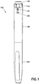
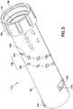
- FIG. 1 is a perspective view of an injection device 100 in accordance with an embodiment of the present invention.
- Injection device 100 includes a cap 104, a body or pen body 108, a dose setting knob (DSK) 112, and an injection button or button 116.
- the pen body 108 includes first and second dosage indicator windows 120 and 124 disposed at a proximal end thereof. As described in greater detail below, dosage numbers disposed on the sleeve (or dose setting sleeve) of the DSK 112 are visible through one of the dosage indicator windows 120 and 124 at a time.
- the dosage indicator windows 120 and 124 are used to set a current desired dosage and the dosage numbers become visible through the each of the dosage indicator windows 120 and 124, but are only visible through one of the dosage indicator windows at a time. That is, according to one embodiment, different dosage indicator windows display different ones of the dosage numbers. Put another way, according to one embodiment, the dosage numbers are consecutively visible in alternating ones of the dosage indicator windows.
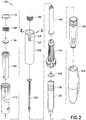
- FIG 2 is an exploded perspective view of the injection device 100.
- the injection device 100 includes a cartridge holder 128 and a medicament cartridge 132 with a stopper 136 movably disposed therein.
- the injection device 100 also includes a wave clip or wave spring clip 140 for supporting the medicament cartridge 132 and biasing the medicament cartridge 132 distally, a brake tower 144, a piston rod 148, a lead screw 152, a dose stop 156, a setback 160, a setback bearing insert 164, and a clicking spring 168.
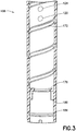
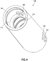
- FIG. 3 is a cross-sectional view of the body 108 taken along line 3-3 of FIG. 2 and FIG. 4 is a perspective view of the body 108.
- the body 108 includes a radially inward protruding wall 176 that, in conjunction with radially inward protruding bosses 180, registers the brake tower 144 relative to the body 108.
- the body 108 includes a cartridge holder connecting thread 184 at a distal end thereof for engaging a corresponding thread on a proximal end of the cartridge holder 128 to connect the cartridge holder 128 and the body 8.
- the body 108 also includes a substantially helical internal thread 172 for guiding movement of the DSK 112 relative to the body 108.
- the DSK 112 shown in FIGS. 5 and 6 , includes a gripping portion 188 and a sleeve portion or sleeve or dose setting sleeve 192 having a pair of keys 194 protruding radially outward therefrom.
- the gripping portion 188 has a plurality of teeth 190 for engaging the setback 160 and a button receiving portion 198 for receiving the button 116, as described in greater detail below.
- the keys 194 slidably engage the internal thread 172 of the body 108 to guide movement of the DSK 112 relative to the body 108.
- the sleeve 192 also has dosage numbers 196 arrayed thereon in fixed relation with one another in a pair of substantially helical patterns.
- a first helical pattern 200 includes even numbers and a second helical pattern 204 includes odd numbers.
- Non-number indicators 208 separate the even numbers of the first helical pattern 200 the odd numbers of the second helical pattern 204.
- the non-number indicators 208 are arrows 208 pointing toward the other helical pattern. For example, each arrow 208 in the first helical pattern 200 points toward a single odd number in the second helical pattern 204 and each arrow 208 in the second helical pattern 204 points toward a single even-numbered in the first helical pattern 200.
- the even numbers of the first helical pattern 200 are visible through the second dosage indicator window 124 and the numbers of the second helical pattern 204 are visible through the first dosage indicator window 120. Further, according to one embodiment, a single one of the dosage numbers 196 is visible at a time. In other words, an even dosage number is visible through the second dosage indicator window 124, or an odd dosage number is visible through the first dosage indicator window 120. Put another way, a dosage number 196 is visible through a single one of the dosage indicator windows 120 and 124 at a time.
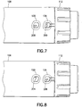
- a non-number indicator 208 is visible through the other dosage indicator window pointing to the dosage number 196 visible through the dosage indicator window 120. More specifically, as shown in FIG. 7 , when a dosage number 196 in the first helical pattern 200 (an even number) is visible through the second dosage indicator window 124, a non-number indicator 208 is visible through the first dosage indicator window 120. Similarly, as shown in FIG. 8 , when for example when a dosage number 196 in the second helical pattern 204 (an odd number) is visible through the first dosage indicator window 120, a non-number indicator 208 is visible through the second dosage indicator window 124.
- the DSK 112 also has an internal dose stop thread 210 and a radially inward protruding dose stop blocker 212 for defining an end-of-dose condition in conjunction with the dose stop 156 and the setback 160.
- the first and second dosage indicator windows 120 and 124 each include a magnifying lens for magnifying the dosage numbers to aid visually impaired users.
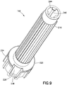
- the brake tower 144 includes a plurality of ratchet teeth 216 disposed on a proximal portion thereof and a base portion 220 disposed at a distal end thereof.
- the base portion 220 includes a plurality of fins 224 and a pair of recessed portions 228.
- the recessed portions 228 engage the bosses 180 of the body 108 and the proximal surface of the base portion 220 registers against the wall 176 of the body 108 when the brake tower 144 is inserted into the distal end of the body 108.
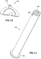
- arms 232 of the wave clip 140 ( FIG. 10 ) engage recesses 236 of the base portion 220 to secure the wave clip 140 to the brake tower 144.
- the interior of the brake tower 144 has a pair of axial piston rod grooves 240 for guiding movement of the piston rod 148, and three limiters 244 for limiting proximal displacement of the piston rod 148.
- the piston rod 148 shown in FIG. 11 , includes a pair of piston rod keys 248 at a proximal end thereof for engaging the piston rod grooves 240 of the brake tower 144.
- the piston rod grooves 240 constrain displacement of the piston rod 148 to be axial relative to the brake tower 144.
- the piston rod 148 has a driving flange 252 disposed at a distal end thereof for engaging the stopper 136, to displace the stopper 136 relative to the medicament cartridge 132.
- the interior of the piston rod 148 has a helical thread 256 for engaging the lead screw 152.
- the lead screw 152 includes a piston rod thread portion 260 for engaging the thread 256 of the piston rod 148.
- An engaging portion 264 connects the lead screw 152 to the brake tower 144, for example, by a snap fit, thereby permitting rotation of the lead screw 152 relative to the brake tower 144 but preventing axial displacement of the lead screw 152 relative to the brake tower 144.
- a substantially cylindrical proximal portion 268 has a raised structure 272 disposed thereon. According to one embodiment, the raised structure 272 has a cross or plus-sign shape.
- Two of the arms of the raised structure 272 extend radially beyond the perimeter of the proximal portion to form a pair of setback keys 276 that slidably engage an axial groove or keyway 280 in the setback 160. Interaction between the setback keys 276 and the keyways 280 constrain displacement of the setback 160 relative to the lead screw 152 to be substantially axial.
- FIGS. 13 and 14 respectively illustrate distal and proximal ends of the setback 160.
- the setback 160 has a receiving portion 282 for receiving the setback bearing insert 164, for example, with a snap fit.
- the setback 160 also includes a plurality of DSK teeth 284, which, as described in greater detail below, engage the teeth 190 of the DSK 112.
- the setback 160 includes a pair of dose stop ridges 286 that engage lateral ends of the dose stop 156. The area between the dose stop ridges 286 defines a sliding surface 290 on which the dose stop 156 slides.
- the setback 160 also includes a pair of cantilevered arms 288, on which a respective pair of brake tower teeth 292 protrude radially inward.
- the cantilevered arms 288 and the brake tower teeth 292 permit one-way rotation of the setback 160 relative to the brake tower 144.
- the interaction between the cantilevered arms 288, the brake teeth 292, and the ratchet teeth 216 permits axial displacement of the setback 160 relative to the brake tower 144.
- the setback bearing insert 164 shown in FIG. 15 , includes an engaging portion 296 received in the receiving portion 282 of the setback 160, a bearing surface 300 against which clicking spring 168 bears, and a post 304 extending proximally from the bearing surface 300.
- the post 304 contacts an internal surface of the injection button 116, which is shown in FIG. 16 .
- the injection button 116 includes a substantially cylindrical internal wall 308 proximally extending in an interior thereof.
- the post 304 fits into the interior of the internal wall 308 and a space between the internal wall 308 and an external wall 312 of the button 116 houses the spring, which bears both on the bearing surface 300 of the setback bearing insert 164 and an internal surface of the button 116.
- the button 116 also has an engagement portion 316 for engaging the button receiving portion 198 of the DSK 112, for example, with a snap fit. According to one embodiment, the button 116 is rotatable relative to the DSK 112.
- a user sets a desired dosage by rotating the DSK 112 in a first direction. Because of the interaction between the keys 194 of the DSK 112 and the helical thread 172 of the body 108, rotation of the DSK 112 proximally displaces the DSK 112 and the setback 160. During this proximal displacement of the setback 160, the brake tower teeth 292 slide axially along the ratchet teeth 216 of the brake tower 144, which is secured to the body 108 via the bosses 180 and the recessed portions 228.
- the engagement of the brake tower teeth 292 and the ratchet teeth 216 prevent rotation of the setback 160 in the first direction.
- the teeth 190 of the DSK 112 rotate past the DSK teeth 284 of the setback 160, thereby providing discrete rotational steps and feedback to the user, for example an audible click and/or tactile feedback.
- the discrete rotational steps correspond to an increase of one dosage number, for example, about 10° of rotation of the DSK 112.
- an even dosage number is visible through the second dosage indicator window 124 (and the corresponding non-number indicator 208 is visible through the first dosage indicator window 120)
- an odd dosage number one higher than the previously visible even number, becomes visible through the first dosage indicator window 120 (and the corresponding non-number indicator 208 becomes visible through the second dosage indicator window 124).
- the user presses the button 116 distally. Because of the interaction between the keys 194 of the DSK 112 and the helical thread 172 of the body 108, the distal displacement of the button 116 causes rotation of the DSK 112 in a second direction, opposite to the first direction. And because rotation of the setback 160 in the second direction is permitted by the engagement of the brake tower teeth 292 and the ratchet teeth 216, rotation of the DSK 112 in the second direction also rotates the setback 160 in the second direction.
- the engaging portion 264 of the lead screw 152 engages the brake tower 144 to permit rotation of the lead screw 152, but not axial displacement thereof relative to the brake tower 144.
- the lead screw rotates, thereby distally displacing the piston rod 148 because of the engagement of the piston rod thread 260 and the internal thread 256 and the engagement between the piston rod keys 248 and the piston rod grooves 240 of the brake tower 144.
- This distal displacement of the piston rod distally displaces the stopper 136 relative to the medicament cartridge 132 and expels medicament from the medicament cartridge 132 through the pen needle.
- FIG. 17 is a perspective view of a dose stop 156 and FIG. 18 is a cross-sectional view illustrating the interaction between the DSK 112 and the dose stop 156 at the occurrence of the end-of-dose condition.
- the dose stop 156 has DSK threads 320 that engage the dose stop thread 210 of the DSK 112.
- the setback 160 displaces proximally but does not rotate in the first direction.
- the rotation of the DSK 112 relative to the setback 160 causes the dose stop 156 to slide distally along the sliding surface 290 of the setback 160 and displace distally relative to the DSK 112.
- the dose stop 156 rotates along with the DSK 112 and the setback 160 and there is no relative displacement between the dose stop 156 and the DSK 112.
- the dose stop 156 contacts the dose stop blocker 212, which prevents further distal displacement of the dose stop 156 relative to the DSK 112.
- the DSK 112 can no longer rotate relative to the setback 160 (i.e., rotate in the first direction) because of the engagement of the DSK threads 320 and the dose stop thread 210 and the engagement between the dose stop ridges 286 and the lateral ends of the dose stop 156.
- This condition defines the end of medicament dosages available from the medicament cartridge 132. In other words, because the user can no longer rotate the DSK 112 in the first direction, no further desired dose can be set. In this state, however, the user can still depress the button 116 to expel the set dosage from the medicament cartridge 132.
- initial displacement of the dose stop 156 relative to the dose stop blocker 212 of the DSK 112 can be calculated to accommodate different volumes of medicament in the medicament cartridge 132.
- the initial axial distance and rotation of the dose stop relative to the dose stop blocker can be calculated.
- the amount of rotation of the DSK 112 to fully dispense a given volume of medicament i.e., the number of unit doses in the medicament cartridge
- the thread pitch of the DSK threads 320 and the dose stop thread 210 determine how far the dose stop 156 is displaced relative to the dose stop blocker 212 during assembly of the injection device 100.
- a desired displacement of the dose stop during cumulative use of the injection device 100 can be used to calculate the thread pitch of DSK threads 320 and the dose stop thread 210.
- demarcations corresponding to different volumes of medicament are disposed on an interior of the DSK so that when a user replaces a medicament cartridge, the user can set the displacement of the dose stop 156 relative to the dose stop blocker 212 corresponding to the volume of medicament in the new medicament cartridge 132.
- the DSK 112 described previously includes 16 discrete dose settings.
- the even and odd dosage numbers 314 and 318 (as well as the non-number indicators 320) on a sleeve 326 of a DSK 324 can be placed closer together in their respective helical patterns.
- the number of teeth disposed at the proximal end of the DSK 324 that interact with the DSK teeth 284 of the setback 160 also increase.
- the discrete rotational steps may be, for example, about 5° of rotation of the DSK 324.
- a larger font can be employed, thereby making use of the device easier for people with impaired vision.
- FIGS. 21-23 illustrate an injection device 328 in accordance with another embodiment of the present invention.
- the injection device 328 includes a DSK 330 and a body 332.
- the body 332 includes first, second, and third dosage indicator windows 336, 340, and 344.
- dosage numbers 348 form helical patterns on a sleeve 352 of the DSK 330. Odd dosage numbers sequentially form a first substantially helical pattern 356 and even dosage numbers sequentially form a second substantially helical pattern.
- non-number indicators 362 form a third substantially helical pattern 364 disposed between the first and second helical patterns 356 and 360. The non-number indicators in the third helical pattern 364 alternately point to the first and second helical patterns.
- the first and second helical patterns 356 and 356 also include non-number indicators, which are disposed between the dosage numbers.
- non-number indicators when a dosage number is visible through one of the three dosage indicator windows 336, 340, and 344, non-number indicators are visible through both of the remaining dosage indicator windows.
- the successive dosage numbers are visible through successive dosage indicator windows upon rotation of the DSK.
- the next sequential dosage number becomes visible through the first dosage indicator window.
- the next sequential dosage number becomes visible through the next-to-last dosage indicator window.
- subsequent dosage numbers become sequentially visible through ordinally lower dosage indicator windows upon rotation of the DSK sleeve.
- the dosage numbers become sequentially visible through the dosage indicator windows from left to right, and then, after becoming visible through the last dosage indicator window, become sequentially visible through the dosage indicator windows from right to left.
- embodiments of the present invention improve the user experience by reducing confusion and making dosage setting easier for users, particularly for visually impaired users.
Description
- The present invention relates generally to an injection device for dispensing a medicament, and more particularly to an injection device having a plurality of windows for setting a dose.
- Various injection devices are known in the art. Many such injection devices have a single window with a pointer for setting the dosage to be injected. It can be difficult for a user to match a scale line of a dose setting mechanism to the pointer, particularly if the user's vision is impaired. Further, in many such injection devices the scale line includes only even numbers, thus requiring interpolation by the user. In addition, the numbers and scale lines are small, adding to the difficulty for the user. Moreover, in such devices, the currently desired dosage number and other adjacent dosage numbers may be visible in the window of the device at the same time, thereby potentially confusing the user. Accordingly, it is desirable for an injection device to make dosage setting easy for a user, to help ensure proper dosing of the injected medicament.
-
WO 2009/141003 A1 discloses a device for administering an ejectable product with a dispensing counter. -
US 2009/293870 A1 discloses a dose information device to be used with a medical administration device comprising drive means for administering a prescribed dose of medicament. - An aspect of the present invention is to provide an injection device in which dosage setting is simplified, particularly for visually impaired users.
- The foregoing and/or other aspects of the present invention are achieved by providing an injection device, including a body for containing and dispensing a medicament, the body having a plurality of dosage indicator windows for indicating a desired dosage of medicament, and a dose set sleeve rotatably connected with the body for setting the desired dosage, the dose set sleeve having a plurality of dosage numbers disposed thereon in fixed relation with one another. Different dosage indicator windows display different ones of the dosage numbers.
- The foregoing and/or other aspects of the present invention are also achieved by providing an injection device, including a body for containing and dispensing a medicament, the body having a plurality of dosage indicator windows for indicating a desired dosage of medicament, and a dose set sleeve rotatably connected with the body for setting the desired dosage, the dose set sleeve having a plurality of dosage numbers disposed thereon. Upon rotating the dose set sleeve to set the desired dosage, the dosage numbers are consecutively visible through alternating ones of the plurality of dosage indicator windows.
- The foregoing and/or other aspects of the present invention are also achieved by providing a method of setting a dose for an injection device having a body and a dose set sleeve having a plurality of dosage numbers arrayed thereon. The method includes rotating the dose set sleeve to make the dosage numbers consecutively visible through alternating ones of a plurality of dosage indicator windows on the body.
- Additional and/or other aspects and advantages of the present invention will be set forth in part in the description that follows and, in part, will be apparent from the description, or may be learned by practice of the invention.
- The above and/or other aspects and advantages of embodiments of the invention will be more readily appreciated from the following detailed description, taken in conjunction with the accompanying drawings, in which:
-
FIG. 1 is a perspective view of an injection device in accordance with an embodiment of the present invention; -
FIG 2 is an exploded view of the device ofFIG. 1 ; -
FIG. 3 is a cross-sectional view of a body of the device ofFIG. 1 taken along line 3-3 ofFIG. 2 ; -
FIG. 4 is a perspective view of the body ofFIG. 2 ; -
FIGS. 5 and6 are perspective views of a dose setting knob (DSK) of the device ofFIG. 1 ; -
FIGS. 7 and 8 are partial perspective views of selected components of the device ofFIG. 1 ; -
FIG. 9 is a perspective view of a brake tower of the device ofFIG. 1 ; -
FIG. 10 is a perspective view of a wave clip of the device ofFIG. 1 ; -
FIG. 11 is a perspective view of a piston rod of the device ofFIG. 1 ; -
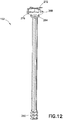
FIG. 12 is a perspective view of a lead screw of the device ofFIG. 1 ; -
FIGS. 13 and14 are perspective views of opposing ends of a setback of the device ofFIG. 1 ; -
FIG. 15 is a perspective view of a setback bearing insert of the device ofFIG. 1 ; -
FIG. 16 is a perspective view of an injection button of the device ofFIG. 1 ; -
FIG. 17 is a perspective view of a dose stop of the device ofFIG. 1 ; -
FIG. 18 is a cross-sectional view of the DSK ofFIGS. 5 and6 and the dose stop ofFIG. 17 ; and -
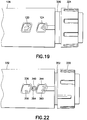
FIG. 19 is a partial perspective view of a body and DSK in accordance with another embodiment of the present invention; -
FIG. 20 is a perspective view of a DSK of the device ofFIG. 19 ; -
FIG. 21 is a perspective view of an injection device in accordance with another embodiment of the present invention; -
FIG. 22 is a partial perspective view of the device ofFIG. 21 ; and -
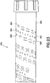
FIG. 23 is a perspective view of a DSK of the device ofFIG. 21 . - Reference will now be made in detail to embodiments of the present invention, examples of which are illustrated in the accompanying drawings, wherein like reference numerals refer to the like elements throughout. The descriptions of these embodiments exemplify the present invention by referring to the drawings.
- This specification refers to "distal," "forward" or "front" interchangeably and "proximal," "rear" or "back" interchangeably to refer to directions or ends of various components. Those terms are used for illustration and discussion purposes only. The particular arrangement of components and their directions of movement contained in the illustrated examples are not to be construed in a limiting sense.
-
FIG. 1 is a perspective view of aninjection device 100 in accordance with an embodiment of the present invention.Injection device 100 includes acap 104, a body orpen body 108, a dose setting knob (DSK) 112, and an injection button orbutton 116. According to one embodiment, thepen body 108 includes first and seconddosage indicator windows dosage indicator windows dosage indicator windows dosage indicator windows -
FIG 2 is an exploded perspective view of theinjection device 100. In addition to thecap 104, thepen body 108, the DSK 112, and theinjection button 116, theinjection device 100 includes acartridge holder 128 and amedicament cartridge 132 with astopper 136 movably disposed therein. Theinjection device 100 also includes a wave clip orwave spring clip 140 for supporting themedicament cartridge 132 and biasing themedicament cartridge 132 distally, abrake tower 144, apiston rod 148, alead screw 152, adose stop 156, asetback 160, a setback bearinginsert 164, and a clickingspring 168. -
FIG. 3 is a cross-sectional view of thebody 108 taken along line 3-3 ofFIG. 2 andFIG. 4 is a perspective view of thebody 108. As shown inFIGS. 3 and4 , thebody 108 includes a radially inwardprotruding wall 176 that, in conjunction with radially inward protrudingbosses 180, registers thebrake tower 144 relative to thebody 108. Further, thebody 108 includes a cartridgeholder connecting thread 184 at a distal end thereof for engaging a corresponding thread on a proximal end of thecartridge holder 128 to connect thecartridge holder 128 and the body 8. Thebody 108 also includes a substantially helicalinternal thread 172 for guiding movement of the DSK 112 relative to thebody 108. - The DSK 112, shown in
FIGS. 5 and6 , includes a grippingportion 188 and a sleeve portion or sleeve ordose setting sleeve 192 having a pair ofkeys 194 protruding radially outward therefrom. Internally, thegripping portion 188 has a plurality ofteeth 190 for engaging thesetback 160 and abutton receiving portion 198 for receiving thebutton 116, as described in greater detail below. Thekeys 194 slidably engage theinternal thread 172 of thebody 108 to guide movement of theDSK 112 relative to thebody 108. Thesleeve 192 also hasdosage numbers 196 arrayed thereon in fixed relation with one another in a pair of substantially helical patterns. - More specifically, a first
helical pattern 200 includes even numbers and a secondhelical pattern 204 includes odd numbers.Non-number indicators 208 separate the even numbers of the firsthelical pattern 200 the odd numbers of the secondhelical pattern 204. According to one embodiment, thenon-number indicators 208 arearrows 208 pointing toward the other helical pattern. For example, eacharrow 208 in the firsthelical pattern 200 points toward a single odd number in the secondhelical pattern 204 and eacharrow 208 in the secondhelical pattern 204 points toward a single even-numbered in the firsthelical pattern 200. - According to one embodiment, the even numbers of the first
helical pattern 200 are visible through the seconddosage indicator window 124 and the numbers of the secondhelical pattern 204 are visible through the firstdosage indicator window 120. Further, according to one embodiment, a single one of thedosage numbers 196 is visible at a time. In other words, an even dosage number is visible through the seconddosage indicator window 124, or an odd dosage number is visible through the firstdosage indicator window 120. Put another way, adosage number 196 is visible through a single one of thedosage indicator windows - Moreover, according to one embodiment, when one of the
dosage numbers 196 is visible through one of the dosage indicator windows, anon-number indicator 208 is visible through the other dosage indicator window pointing to thedosage number 196 visible through thedosage indicator window 120. More specifically, as shown inFIG. 7 , when adosage number 196 in the first helical pattern 200 (an even number) is visible through the seconddosage indicator window 124, anon-number indicator 208 is visible through the firstdosage indicator window 120. Similarly, as shown inFIG. 8 , when for example when adosage number 196 in the second helical pattern 204 (an odd number) is visible through the firstdosage indicator window 120, anon-number indicator 208 is visible through the seconddosage indicator window 124. - In addition, as described in greater detail below, the
DSK 112 also has an internaldose stop thread 210 and a radially inward protrudingdose stop blocker 212 for defining an end-of-dose condition in conjunction with thedose stop 156 and thesetback 160. Further, according to one embodiment, the first and seconddosage indicator windows - As shown in
FIG. 9 , thebrake tower 144 includes a plurality ofratchet teeth 216 disposed on a proximal portion thereof and abase portion 220 disposed at a distal end thereof. Thebase portion 220 includes a plurality offins 224 and a pair of recessedportions 228. The recessedportions 228 engage thebosses 180 of thebody 108 and the proximal surface of thebase portion 220 registers against thewall 176 of thebody 108 when thebrake tower 144 is inserted into the distal end of thebody 108. Further,arms 232 of the wave clip 140 (FIG. 10 ) engagerecesses 236 of thebase portion 220 to secure thewave clip 140 to thebrake tower 144. The interior of thebrake tower 144 has a pair of axialpiston rod grooves 240 for guiding movement of thepiston rod 148, and threelimiters 244 for limiting proximal displacement of thepiston rod 148. - The
piston rod 148, shown inFIG. 11 , includes a pair ofpiston rod keys 248 at a proximal end thereof for engaging thepiston rod grooves 240 of thebrake tower 144. Thepiston rod grooves 240 constrain displacement of thepiston rod 148 to be axial relative to thebrake tower 144. In addition, thepiston rod 148 has a drivingflange 252 disposed at a distal end thereof for engaging thestopper 136, to displace thestopper 136 relative to themedicament cartridge 132. Further, the interior of thepiston rod 148 has ahelical thread 256 for engaging thelead screw 152. - As shown in
FIG. 12 , thelead screw 152 includes a pistonrod thread portion 260 for engaging thethread 256 of thepiston rod 148. An engagingportion 264 connects thelead screw 152 to thebrake tower 144, for example, by a snap fit, thereby permitting rotation of thelead screw 152 relative to thebrake tower 144 but preventing axial displacement of thelead screw 152 relative to thebrake tower 144. Additionally, a substantially cylindricalproximal portion 268 has a raisedstructure 272 disposed thereon. According to one embodiment, the raisedstructure 272 has a cross or plus-sign shape. Two of the arms of the raisedstructure 272 extend radially beyond the perimeter of the proximal portion to form a pair ofsetback keys 276 that slidably engage an axial groove orkeyway 280 in thesetback 160. Interaction between thesetback keys 276 and thekeyways 280 constrain displacement of thesetback 160 relative to thelead screw 152 to be substantially axial. -
FIGS. 13 and14 respectively illustrate distal and proximal ends of thesetback 160. In addition to the axial groove orkeyway 280 described previously, thesetback 160 has a receivingportion 282 for receiving thesetback bearing insert 164, for example, with a snap fit. Thesetback 160 also includes a plurality ofDSK teeth 284, which, as described in greater detail below, engage theteeth 190 of theDSK 112. Further, as described in greater detail below, thesetback 160 includes a pair of dose stopridges 286 that engage lateral ends of thedose stop 156. The area between the dose stopridges 286 defines a slidingsurface 290 on which the dose stop 156 slides. - As shown in
FIG. 14 , thesetback 160 also includes a pair ofcantilevered arms 288, on which a respective pair ofbrake tower teeth 292 protrude radially inward. In conjunction with theratchet teeth 216 of the brake tower 144 (FIG. 9 ), the cantileveredarms 288 and thebrake tower teeth 292 permit one-way rotation of thesetback 160 relative to thebrake tower 144. Further, the interaction between the cantileveredarms 288, thebrake teeth 292, and theratchet teeth 216 permits axial displacement of thesetback 160 relative to thebrake tower 144. - The
setback bearing insert 164, shown inFIG. 15 , includes an engagingportion 296 received in the receivingportion 282 of thesetback 160, a bearingsurface 300 against which clickingspring 168 bears, and apost 304 extending proximally from the bearingsurface 300. Thepost 304 contacts an internal surface of theinjection button 116, which is shown inFIG. 16 . Theinjection button 116 includes a substantially cylindricalinternal wall 308 proximally extending in an interior thereof. Thepost 304 fits into the interior of theinternal wall 308 and a space between theinternal wall 308 and anexternal wall 312 of thebutton 116 houses the spring, which bears both on thebearing surface 300 of thesetback bearing insert 164 and an internal surface of thebutton 116. Thebutton 116 also has anengagement portion 316 for engaging thebutton receiving portion 198 of theDSK 112, for example, with a snap fit. According to one embodiment, thebutton 116 is rotatable relative to theDSK 112. - During operation of the
injection device 100, preferably after connecting a pen needle to thecartridge holder 128 and themedicament cartridge 132, a user sets a desired dosage by rotating theDSK 112 in a first direction. Because of the interaction between thekeys 194 of theDSK 112 and thehelical thread 172 of thebody 108, rotation of theDSK 112 proximally displaces theDSK 112 and thesetback 160. During this proximal displacement of thesetback 160, thebrake tower teeth 292 slide axially along theratchet teeth 216 of thebrake tower 144, which is secured to thebody 108 via thebosses 180 and the recessedportions 228. - The engagement of the
brake tower teeth 292 and theratchet teeth 216 prevent rotation of thesetback 160 in the first direction. In addition, theteeth 190 of theDSK 112 rotate past theDSK teeth 284 of thesetback 160, thereby providing discrete rotational steps and feedback to the user, for example an audible click and/or tactile feedback. According to one embodiment, the discrete rotational steps correspond to an increase of one dosage number, for example, about 10° of rotation of theDSK 112. Thus, if an even dosage number is visible through the second dosage indicator window 124 (and the correspondingnon-number indicator 208 is visible through the first dosage indicator window 120), as the user rotates theDSK 112 by a single discrete rotational step, an odd dosage number, one higher than the previously visible even number, becomes visible through the first dosage indicator window 120 (and the correspondingnon-number indicator 208 becomes visible through the second dosage indicator window 124). - Subsequent to setting the desired dosage, the user presses the
button 116 distally. Because of the interaction between thekeys 194 of theDSK 112 and thehelical thread 172 of thebody 108, the distal displacement of thebutton 116 causes rotation of theDSK 112 in a second direction, opposite to the first direction. And because rotation of thesetback 160 in the second direction is permitted by the engagement of thebrake tower teeth 292 and theratchet teeth 216, rotation of theDSK 112 in the second direction also rotates thesetback 160 in the second direction. - Additionally, as previously noted, the engaging
portion 264 of thelead screw 152 engages thebrake tower 144 to permit rotation of thelead screw 152, but not axial displacement thereof relative to thebrake tower 144. Thus, as thesetback 160 rotates in the second direction, because of the keyed engagement of thesetback key 276 and thegroove 280, the lead screw rotates, thereby distally displacing thepiston rod 148 because of the engagement of thepiston rod thread 260 and theinternal thread 256 and the engagement between thepiston rod keys 248 and thepiston rod grooves 240 of thebrake tower 144. This distal displacement of the piston rod distally displaces thestopper 136 relative to themedicament cartridge 132 and expels medicament from themedicament cartridge 132 through the pen needle. -
FIG. 17 is a perspective view of adose stop 156 andFIG. 18 is a cross-sectional view illustrating the interaction between theDSK 112 and the dose stop 156 at the occurrence of the end-of-dose condition. Thedose stop 156 hasDSK threads 320 that engage thedose stop thread 210 of theDSK 112. As noted previously, when the user rotates theDSK 112 in the first direction to set the desired dosage, thesetback 160 displaces proximally but does not rotate in the first direction. Because of the engagement of theDSK threads 320 and thedose stop thread 210 and the engagement between the dose stopridges 286 and the lateral ends of thedose stop 156, the rotation of theDSK 112 relative to thesetback 160 causes the dose stop 156 to slide distally along the slidingsurface 290 of thesetback 160 and displace distally relative to theDSK 112. When theDSK 112 and thesetback 160 rotate together in the second direction as thebutton 116 is pushed distally by the user, thedose stop 156 rotates along with theDSK 112 and thesetback 160 and there is no relative displacement between thedose stop 156 and theDSK 112. - Upon sufficient cumulative rotation of the
DSK 112 relative to thesetback 160, the dose stop 156 contacts thedose stop blocker 212, which prevents further distal displacement of the dose stop 156 relative to theDSK 112. When this occurs, theDSK 112 can no longer rotate relative to the setback 160 (i.e., rotate in the first direction) because of the engagement of theDSK threads 320 and thedose stop thread 210 and the engagement between the dose stopridges 286 and the lateral ends of thedose stop 156. This condition, as shown inFIG. 18 , defines the end of medicament dosages available from themedicament cartridge 132. In other words, because the user can no longer rotate theDSK 112 in the first direction, no further desired dose can be set. In this state, however, the user can still depress thebutton 116 to expel the set dosage from themedicament cartridge 132. - Using the thread pitch of the
DSK threads 320 and thedose stop thread 210, initial displacement of the dose stop 156 relative to thedose stop blocker 212 of theDSK 112 can be calculated to accommodate different volumes of medicament in themedicament cartridge 132. In other words, the initial axial distance and rotation of the dose stop relative to the dose stop blocker can be calculated. Put a different way, the amount of rotation of theDSK 112 to fully dispense a given volume of medicament (i.e., the number of unit doses in the medicament cartridge), as well as the thread pitch of theDSK threads 320 and thedose stop thread 210, determine how far thedose stop 156 is displaced relative to thedose stop blocker 212 during assembly of theinjection device 100. - Conversely, a desired displacement of the dose stop during cumulative use of the
injection device 100 can be used to calculate the thread pitch ofDSK threads 320 and thedose stop thread 210. According to one embodiment, demarcations corresponding to different volumes of medicament are disposed on an interior of the DSK so that when a user replaces a medicament cartridge, the user can set the displacement of the dose stop 156 relative to thedose stop blocker 212 corresponding to the volume of medicament in thenew medicament cartridge 132. - The
DSK 112 described previously (FIGS. 5 and6 ) includes 16 discrete dose settings. In accordance with another embodiment of the present invention, as shown inFIGS. 19 and20 , if it is desired to have a smaller discrete dosage unit (or discrete rotational step), the even andodd dosage numbers 314 and 318 (as well as the non-number indicators 320) on asleeve 326 of aDSK 324 can be placed closer together in their respective helical patterns. Correspondingly, the number of teeth disposed at the proximal end of theDSK 324 that interact with theDSK teeth 284 of thesetback 160 also increase. For example, the discrete rotational steps may be, for example, about 5° of rotation of theDSK 324. Further, by decreasing the spacing between dosage numbers, even if there is not a corresponding increase in the number of teeth at the proximal end of theDSK 324, a larger font can be employed, thereby making use of the device easier for people with impaired vision. - In another effort to decrease spacing between dosage numbers on the DSK and/or enlarge the font size and/or decrease the discrete dosage unit,
FIGS. 21-23 illustrate aninjection device 328 in accordance with another embodiment of the present invention. As shown inFIGS. 21 and22 , theinjection device 328 includes aDSK 330 and abody 332. Thebody 332 includes first, second, and thirddosage indicator windows - Similar to the previously described embodiments,
dosage numbers 348 form helical patterns on asleeve 352 of theDSK 330. Odd dosage numbers sequentially form a first substantiallyhelical pattern 356 and even dosage numbers sequentially form a second substantially helical pattern. In contrast to the previously described embodiments, however,non-number indicators 362 form a third substantiallyhelical pattern 364 disposed between the first and secondhelical patterns helical pattern 364 alternately point to the first and second helical patterns. Thus, according to one embodiment, as shown inFIG. 22 , when an even dosage number from the secondhelical pattern 360 is visible through the thirddosage indicator window 344, anon-number indicator 362 pointing to the visible even dosage number is visible through the seconddosage indicator window 340. Similarly, when an odd dosage number from the firsthelical pattern 356 is visible through the firstdosage indicator window 336, anon-number indicator 362 pointing to the visible odd dosage number is visible through the seconddosage indicator window 340. - According to another embodiment, in addition to the third
helical pattern 364, the first and secondhelical patterns dosage indicator windows - According to another embodiment, there may be four or more helical patterns arrayed on a DSK sleeve and a corresponding number of dosage indicator windows. In such an embodiment, the successive dosage numbers are visible through successive dosage indicator windows upon rotation of the DSK. According to one embodiment, when a dosage number is visible through the last dosage indicator window, upon rotation of the DSK sleeve, the next sequential dosage number becomes visible through the first dosage indicator window.
- According to another embodiment, when a dosage number is visible through the last dosage indicator window, upon rotation of the DSK sleeve, the next sequential dosage number becomes visible through the next-to-last dosage indicator window. Additionally, subsequent dosage numbers become sequentially visible through ordinally lower dosage indicator windows upon rotation of the DSK sleeve. In other words, when the DSK sleeve rotates, the dosage numbers become sequentially visible through the dosage indicator windows from left to right, and then, after becoming visible through the last dosage indicator window, become sequentially visible through the dosage indicator windows from right to left.
- Thus, embodiments of the present invention improve the user experience by reducing confusion and making dosage setting easier for users, particularly for visually impaired users.
- Although only a few exemplary embodiments of the present invention have been described in detail above, those skilled in the art will readily appreciate that many modifications are possible in the exemplary embodiments without materially departing from the novel teachings and advantages of this invention. Accordingly, all such modifications are intended to be included within the scope of the appended claims and equivalents thereof.
Claims (10)
- An injection device (100), comprising:a body (108) for containing and dispensing a medicament, the body (108) having a plurality of dosage indicator windows (120, 124, 336, 340, 344) for indicating a desired dosage of medicament; anda dose set sleeve (192, 326,352) rotatably connected with the body (108) for setting the desired dosage, the dose set sleeve (192, 326,352) having a plurality of dosage numbers (196, 314,318, 348) disposed thereon;characterized in thatthe dosage numbers (196, 314,318, 348) and at least one of blank spaces and non-number indicators are arranged on the dose set sleeve (192, 326,352) in parallel helical patterns (356, 360, 364) such that upon rotating the dose set sleeve (192, 326,352) to set the desired dosage, the dosage numbers (196, 314,318, 348) are consecutively visible through alternating ones of the plurality of dosage indicator windows (120, 124, 336, 340, 344) while a dosage number is not visible through one or more other dosage indicator windows (120, 124, 336, 340, 344) of the plurality.
- The injection device (100) according to claim 1, wherein the dose set sleeve (192, 326,352) is rotatably connected with the body (108) to ratchet for each dosage unit; and
the dose set sleeve (192, 326,352) is connected with a knob for interfacing with a user. - The injection device (100) according to claim 1, wherein upon a dosage number being visible through one of the dosage indicator windows (120, 124, 336, 340, 344), a non-number indicator is visible through another one of the dosage indicator windows (120, 124, 336, 340, 344).
- The injection device (100) according to claim 3, wherein the non-number indicator is or comprises an arrow.
- The injection device (100) according to claim 1, wherein even dosage numbers (196, 314,318, 348) are only visible through the one of the dosage indicator windows (120, 124, 336, 340, 344) and odd dosage numbers (196, 314,318, 348) are only visible through another one of the dosage indicator windows (120, 124, 336, 340, 344).
- The injection device (100) according to claim 5, wherein:the plurality of dosage indicator windows (120, 124, 336, 340, 344) comprises a pair of dosage indicator windows (120, 124, 336, 340, 344); andthe dosage numbers (196, 314,318, 348) are arrayed on the sleeve in a pair of substantially helical patterns (356, 360, 364), the first helical pattern (356, 360, 364) comprising even numbers and the second helical pattern (356, 360, 364) comprising odd numbers.
- The injection device (100) according to claim 6, wherein the even numbers are separated by non-number indicators and the odd numbers are separated by non-number indicators; and
wherein upon a dosage number being visible through one of the pair of dosage indicator windows (120, 124, 336, 340, 344), the non-number indicator is visible through the remaining one of the pair of dosage indicator windows (120, 124, 336, 340, 344). - The injection device (100) according to claim 1, wherein each or at least one of the dosage indicator windows (120, 124, 336, 340, 344) comprises a magnifying lens.
- The injection device (100) according to claim 5, wherein the plurality of dosage indicator windows (120, 124, 336, 340, 344) comprises first, second, and third dosage indicator windows (120, 124, 336, 340, 344);
wherein the dosage numbers (196, 314,318, 348) are arrayed on the sleeve in a pair of substantially helical patterns (356, 360, 364), the first helical pattern (356, 360, 364) comprising even numbers and the second helical pattern (356, 360, 364) comprising odd numbers;
wherein non-number indicators are arrayed on the sleeve in a substantially helical pattern (356, 360, 364); and
wherein upon a dosage number being visible through one of the dosage indicator windows (120, 124, 336, 340, 344), the non-number indicator is visible through another one of the dosage indicator windows (120, 124, 336, 340, 344) indicating which dosage indicator window (120, 124, 336, 340, 344) a current dosage number is visible through. - A method of setting a dose for an injection device (100) having a body (108) and a dose set sleeve (192, 326,352) having a plurality of dosage numbers (196, 314,318, 348) arrayed thereon in fixed relation with one another in parallel helical patterns (356, 360, 364), the method comprising:
rotating the dose set sleeve (192, 326,352) to make the dosage numbers (196, 314,318, 348) consecutively visible through alternating ones of a plurality of dosage indicator windows (120, 124, 336, 340, 344) on the body (108) while a dosage number is not visible through one or more other dosage indicator windows (120, 124, 336, 340, 344) of the plurality.
Priority Applications (2)
| Application Number | Priority Date | Filing Date | Title |
|---|---|---|---|
| ES19156171T ES2871477T3 (en) | 2011-05-19 | 2011-05-19 | Injection device with multiple dose setting windows |
| EP19156171.1A EP3511040B1 (en) | 2011-05-19 | 2011-05-19 | Injection device with plural dosage setting windows |
Applications Claiming Priority (3)
| Application Number | Priority Date | Filing Date | Title |
|---|---|---|---|
| PCT/US2011/000898 WO2012158138A1 (en) | 2011-05-19 | 2011-05-19 | Injection device with plural dosage setting windows |
| EP19156171.1A EP3511040B1 (en) | 2011-05-19 | 2011-05-19 | Injection device with plural dosage setting windows |
| EP11865688.3A EP2709697B1 (en) | 2011-05-19 | 2011-05-19 | Injection device with plural dosage setting windows |
Related Parent Applications (1)
| Application Number | Title | Priority Date | Filing Date |
|---|---|---|---|
| EP11865688.3A Division EP2709697B1 (en) | 2011-05-19 | 2011-05-19 | Injection device with plural dosage setting windows |
Publications (2)
| Publication Number | Publication Date |
|---|---|
| EP3511040A1 EP3511040A1 (en) | 2019-07-17 |
| EP3511040B1 true EP3511040B1 (en) | 2021-03-10 |
Family
ID=47177215
Family Applications (2)
| Application Number | Title | Priority Date | Filing Date |
|---|---|---|---|
| EP19156171.1A Active EP3511040B1 (en) | 2011-05-19 | 2011-05-19 | Injection device with plural dosage setting windows |
| EP11865688.3A Active EP2709697B1 (en) | 2011-05-19 | 2011-05-19 | Injection device with plural dosage setting windows |
Family Applications After (1)
| Application Number | Title | Priority Date | Filing Date |
|---|---|---|---|
| EP11865688.3A Active EP2709697B1 (en) | 2011-05-19 | 2011-05-19 | Injection device with plural dosage setting windows |
Country Status (8)
| Country | Link |
|---|---|
| US (1) | US9358344B2 (en) |
| EP (2) | EP3511040B1 (en) |
| JP (1) | JP5805309B2 (en) |
| CN (1) | CN103648556B (en) |
| BR (2) | BR112013029580B1 (en) |
| DK (1) | DK2709697T3 (en) |
| ES (2) | ES2727835T3 (en) |
| WO (1) | WO2012158138A1 (en) |
Families Citing this family (16)
| Publication number | Priority date | Publication date | Assignee | Title |
|---|---|---|---|---|
| CH703993A2 (en) | 2012-02-09 | 2012-03-15 | Tecpharma Licensing Ag | Injection device for dispensing fluid product, has bearing coupling surfaces that are formed in coupling mechanism to produce acoustic/tactile signals corresponding to adjusted or corrected dose during dose dispensing process |
| CN105102034A (en) | 2013-04-10 | 2015-11-25 | 赛诺菲 | Drive mechanism for a drug delivery device |
| CN105530970B (en) * | 2013-09-10 | 2021-04-06 | 赛诺菲 | Dose indicating mechanism for a drug delivery device |
| US20160317751A1 (en) * | 2013-12-20 | 2016-11-03 | Novo Nordisk A/S | Mechanical Dose Expelled Indicator |
| CN106470720A (en) * | 2014-05-26 | 2017-03-01 | 赛诺菲 | Display assembly for injection device |
| WO2015181187A1 (en) | 2014-05-28 | 2015-12-03 | Sanofi-Aventis Deutschland Gmbh | Dose indicating mechanism for a drug delivery device and drug delivery device |
| EP3546894A1 (en) * | 2014-06-10 | 2019-10-02 | Sanofi-Aventis Deutschland GmbH | Sensor device removably attachable to a drug delivery device |
| US20170326302A1 (en) * | 2015-01-08 | 2017-11-16 | Novo Nordisk A/S | Drug Injection Device with Visual End-Of-Contents Indicator System |
| CN105727400B (en) * | 2016-02-03 | 2023-02-17 | 苏州翰尔西医疗器械开发有限公司 | Drug delivery device |
| DK3509669T3 (en) | 2016-09-09 | 2021-05-31 | Sanofi Aventis Deutschland | DATA COLLECTION DEVICE FOR FIXING ON AN INJECTION DEVICE |
| CN109331293B (en) * | 2018-11-19 | 2021-08-03 | 东莞市彦成塑胶原料有限公司 | Injection pen |
| CN110368555A (en) * | 2019-05-27 | 2019-10-25 | 山西大医院(山西医学科学院) | Insulin injection pen with flashing light prompt facility |
| US20210008282A1 (en) * | 2019-07-09 | 2021-01-14 | Becton, Dickinson And Company | Self-Controllable Load Spring Washer |
| BR112022019499A2 (en) * | 2020-03-27 | 2022-12-06 | Becton Dickinson Co | IMPROVED SYSTEMS, COMPONENTS AND THEIR COMBINATIONS FOR PEN-TYPE INJECTION DEVICES |
| WO2022066904A1 (en) * | 2020-09-25 | 2022-03-31 | Becton, Dickinson And Company | Biasing member for medical injection device |
| AU2021347257A1 (en) * | 2020-09-25 | 2023-05-04 | Becton, Dickinson And Company | Medical injection device with a retained biasing component |
Family Cites Families (24)
| Publication number | Priority date | Publication date | Assignee | Title |
|---|---|---|---|---|
| US2279858A (en) | 1942-04-14 | Cash register | ||
| GB789629A (en) | 1955-11-01 | 1958-01-22 | Loblite Ltd | Improvements in or relating to rules and calculators |
| EP0828527B1 (en) | 1996-04-02 | 2002-07-31 | Disetronic Licensing AG | Injection device |
| US6221053B1 (en) * | 1998-02-20 | 2001-04-24 | Becton, Dickinson And Company | Multi-featured medication delivery pen |
| JP2000070368A (en) * | 1998-08-27 | 2000-03-07 | Shimadzu Corp | Needle-less syringe |
| JP2000182135A (en) * | 1998-12-18 | 2000-06-30 | Matsushita Refrig Co Ltd | Article storage device of automatic vending machine |
| JP4792670B2 (en) * | 2001-07-23 | 2011-10-12 | 株式会社島津製作所 | Needleless syringe |
| US9205197B2 (en) | 2003-03-03 | 2015-12-08 | Sanofi-Aventis Deutschland Gmbh | Drug delivery device dose setting mechanism |
| WO2006058883A2 (en) | 2004-12-01 | 2006-06-08 | Novo Nordisk A/S | Injection device |
| FR2883400B1 (en) | 2005-03-16 | 2007-06-15 | Valois Sas | DOSAGE INDICATING DEVICE FOR DISPENSING FLUID OR PULVERULENT PRODUCTS |
| DE102005023824A1 (en) * | 2005-05-24 | 2006-12-07 | Tecpharma Licensing Ag | Dosing device for an injection device |
| US20080269688A1 (en) * | 2005-12-08 | 2008-10-30 | Jose Colucci | Dose Indicating Assembly of a Pharmaceutical Injection Device |
| EP2007451B1 (en) * | 2006-03-21 | 2018-11-07 | SHL Group AB | Dose information device |
| DE102007026083A1 (en) * | 2007-05-25 | 2008-11-27 | Haselmeier S.A.R.L. | injection device |
| WO2009141003A1 (en) * | 2008-05-20 | 2009-11-26 | Tecpharma Licensing Ag | Device for administering an injectable product with a dispensing counter |
| EP2123317A1 (en) | 2008-05-20 | 2009-11-25 | Sanofi-Aventis Deutschland GmbH | Drive assembly suitable for use in drug delivery device and drug delivery device |
| PT2310073E (en) | 2008-07-09 | 2013-01-14 | Sanofi Aventis Deutschland | Medication delivery device and method of assembling a medication delivery device |
| DE202008011175U1 (en) * | 2008-08-18 | 2010-01-07 | Haselmeier Gmbh | injection device |
| EP2201971A1 (en) * | 2008-12-23 | 2010-06-30 | Sanofi-Aventis Deutschland GmbH | Drug delivery device |
| TR201807257T4 (en) * | 2009-02-26 | 2018-06-21 | Shl Group Ab | Dose adjustment mechanisms. |
| US20110015576A1 (en) | 2009-06-01 | 2011-01-20 | Sanofi-Aventis Deutschland Gmbh | Medicament identification system for multi-dose injection devices |
| CA2779383A1 (en) | 2009-12-02 | 2011-06-09 | Sanofi-Aventis Deutschland Gmbh | Dose display mechanism for a drug delivery device |
| EP3323449B1 (en) * | 2011-03-16 | 2019-07-03 | Becton, Dickinson and Company | Multiple use disposable injection pen |
| US9452265B2 (en) * | 2011-03-18 | 2016-09-27 | Becton, Dickinson And Company | End of injection indicator for injection pen |
-
2011
- 2011-05-19 JP JP2014511328A patent/JP5805309B2/en active Active
- 2011-05-19 DK DK11865688.3T patent/DK2709697T3/en active
- 2011-05-19 US US14/118,193 patent/US9358344B2/en active Active
- 2011-05-19 ES ES11865688T patent/ES2727835T3/en active Active
- 2011-05-19 CN CN201180071894.8A patent/CN103648556B/en active Active
- 2011-05-19 ES ES19156171T patent/ES2871477T3/en active Active
- 2011-05-19 EP EP19156171.1A patent/EP3511040B1/en active Active
- 2011-05-19 WO PCT/US2011/000898 patent/WO2012158138A1/en active Application Filing
- 2011-05-19 EP EP11865688.3A patent/EP2709697B1/en active Active
- 2011-05-19 BR BR112013029580-5A patent/BR112013029580B1/en active IP Right Grant
- 2011-05-19 BR BR122020020451-6A patent/BR122020020451B1/en active IP Right Grant
Non-Patent Citations (1)
| Title |
|---|
| None * |
Also Published As
| Publication number | Publication date |
|---|---|
| WO2012158138A1 (en) | 2012-11-22 |
| US9358344B2 (en) | 2016-06-07 |
| ES2727835T3 (en) | 2019-10-21 |
| EP2709697A4 (en) | 2015-01-07 |
| EP2709697B1 (en) | 2019-03-06 |
| BR112013029580A2 (en) | 2016-12-06 |
| CN103648556B (en) | 2016-01-27 |
| US20140094765A1 (en) | 2014-04-03 |
| DK2709697T3 (en) | 2019-05-06 |
| EP3511040A1 (en) | 2019-07-17 |
| BR122020020451B1 (en) | 2021-05-25 |
| JP5805309B2 (en) | 2015-11-04 |
| CN103648556A (en) | 2014-03-19 |
| JP2014519892A (en) | 2014-08-21 |
| ES2871477T3 (en) | 2021-10-29 |
| EP2709697A1 (en) | 2014-03-26 |
| BR112013029580B1 (en) | 2021-01-19 |
Similar Documents
| Publication | Publication Date | Title |
|---|---|---|
| EP3511040B1 (en) | Injection device with plural dosage setting windows | |
| JP6553689B2 (en) | Multi-use disposable injection pen | |
| US9956351B2 (en) | Injection device without a gearing | |
| DK1944050T3 (en) | Improvements relating to drive mechanisms suitable for use in drug delivery devices | |
| DK2303369T3 (en) | Drive as SUITABLE FOR USE IN A DEVICE FOR PHARMACEUTICAL FEED AND DEVICE FOR PHARMACEUTICAL FEED | |
| DK1656170T3 (en) | Drug delivery device with three screw threads for mechanical advantage | |
| EP1610847B1 (en) | Dose dial and drive mechanism suitable for use in drug delivery devices | |
| EP1601396B2 (en) | Improvements in and relating to drive mechanisms suitable for use in drug delivery devices | |
| DK1838367T3 (en) | PROCEDURE FOR COLLECTION OF PHARMACEUTICAL ADMINISTRATION DEVICES | |
| EP3164172B1 (en) | Spring arrangement and drug delivery device herewith | |
| JP2004500904A5 (en) | ||
| JP2006519074A (en) | Drive mechanism of drug delivery device | |
| JP2022071113A (en) | Medication delivery device with gear set dosage system | |
| EP3242698A1 (en) | Drug injection device with visual end-of-contents indicator system | |
| JP7349443B2 (en) | Drive mechanism for injection device | |
| JP2017064536A (en) | Multiple use disposable injection pen | |
| CN113301931A (en) | Injection device |
Legal Events
| Date | Code | Title | Description |
|---|---|---|---|
| PUAI | Public reference made under article 153(3) epc to a published international application that has entered the european phase |
Free format text: ORIGINAL CODE: 0009012 |
|
| STAA | Information on the status of an ep patent application or granted ep patent |
Free format text: STATUS: THE APPLICATION HAS BEEN PUBLISHED |
|
| AC | Divisional application: reference to earlier application |
Ref document number: 2709697 Country of ref document: EP Kind code of ref document: P |
|
| AK | Designated contracting states |
Kind code of ref document: A1 Designated state(s): AL AT BE BG CH CY CZ DE DK EE ES FI FR GB GR HR HU IE IS IT LI LT LU LV MC MK MT NL NO PL PT RO RS SE SI SK SM TR |
|
| STAA | Information on the status of an ep patent application or granted ep patent |
Free format text: STATUS: REQUEST FOR EXAMINATION WAS MADE |
|
| 17P | Request for examination filed |
Effective date: 20200113 |
|
| RBV | Designated contracting states (corrected) |
Designated state(s): AL AT BE BG CH CY CZ DE DK EE ES FI FR GB GR HR HU IE IS IT LI LT LU LV MC MK MT NL NO PL PT RO RS SE SI SK SM TR |
|
| RIC1 | Information provided on ipc code assigned before grant |
Ipc: A61M 5/31 20060101ALN20200717BHEP Ipc: A61M 5/315 20060101AFI20200717BHEP Ipc: A61M 5/24 20060101ALI20200717BHEP |
|
| RIC1 | Information provided on ipc code assigned before grant |
Ipc: A61M 5/24 20060101ALI20200731BHEP Ipc: A61M 5/315 20060101AFI20200731BHEP Ipc: A61M 5/31 20060101ALN20200731BHEP |
|
| GRAP | Despatch of communication of intention to grant a patent |
Free format text: ORIGINAL CODE: EPIDOSNIGR1 |
|
| STAA | Information on the status of an ep patent application or granted ep patent |
Free format text: STATUS: GRANT OF PATENT IS INTENDED |
|
| RAP1 | Party data changed (applicant data changed or rights of an application transferred) |
Owner name: BECTON, DICKINSON AND COMPANY |
|
| INTG | Intention to grant announced |
Effective date: 20200917 |
|
| GRAS | Grant fee paid |
Free format text: ORIGINAL CODE: EPIDOSNIGR3 |
|
| STAA | Information on the status of an ep patent application or granted ep patent |
Free format text: STATUS: GRANT OF PATENT IS INTENDED |
|
| GRAA | (expected) grant |
Free format text: ORIGINAL CODE: 0009210 |
|
| STAA | Information on the status of an ep patent application or granted ep patent |
Free format text: STATUS: THE PATENT HAS BEEN GRANTED |
|
| AC | Divisional application: reference to earlier application |
Ref document number: 2709697 Country of ref document: EP Kind code of ref document: P |
|
| AK | Designated contracting states |
Kind code of ref document: B1 Designated state(s): AL AT BE BG CH CY CZ DE DK EE ES FI FR GB GR HR HU IE IS IT LI LT LU LV MC MK MT NL NO PL PT RO RS SE SI SK SM TR |
|
| REG | Reference to a national code |
Ref country code: GB Ref legal event code: FG4D |
|
| REG | Reference to a national code |
Ref country code: AT Ref legal event code: REF Ref document number: 1369122 Country of ref document: AT Kind code of ref document: T Effective date: 20210315 Ref country code: CH Ref legal event code: EP |
|
| REG | Reference to a national code |
Ref country code: DE Ref legal event code: R096 Ref document number: 602011070387 Country of ref document: DE |
|
| REG | Reference to a national code |
Ref country code: IE Ref legal event code: FG4D |
|
| REG | Reference to a national code |
Ref country code: LT Ref legal event code: MG9D |
|
| PG25 | Lapsed in a contracting state [announced via postgrant information from national office to epo] |
Ref country code: BG Free format text: LAPSE BECAUSE OF FAILURE TO SUBMIT A TRANSLATION OF THE DESCRIPTION OR TO PAY THE FEE WITHIN THE PRESCRIBED TIME-LIMIT Effective date: 20210610 Ref country code: FI Free format text: LAPSE BECAUSE OF FAILURE TO SUBMIT A TRANSLATION OF THE DESCRIPTION OR TO PAY THE FEE WITHIN THE PRESCRIBED TIME-LIMIT Effective date: 20210310 Ref country code: HR Free format text: LAPSE BECAUSE OF FAILURE TO SUBMIT A TRANSLATION OF THE DESCRIPTION OR TO PAY THE FEE WITHIN THE PRESCRIBED TIME-LIMIT Effective date: 20210310 Ref country code: GR Free format text: LAPSE BECAUSE OF FAILURE TO SUBMIT A TRANSLATION OF THE DESCRIPTION OR TO PAY THE FEE WITHIN THE PRESCRIBED TIME-LIMIT Effective date: 20210611 Ref country code: LT Free format text: LAPSE BECAUSE OF FAILURE TO SUBMIT A TRANSLATION OF THE DESCRIPTION OR TO PAY THE FEE WITHIN THE PRESCRIBED TIME-LIMIT Effective date: 20210310 Ref country code: NO Free format text: LAPSE BECAUSE OF FAILURE TO SUBMIT A TRANSLATION OF THE DESCRIPTION OR TO PAY THE FEE WITHIN THE PRESCRIBED TIME-LIMIT Effective date: 20210610 |
|
| REG | Reference to a national code |
Ref country code: AT Ref legal event code: MK05 Ref document number: 1369122 Country of ref document: AT Kind code of ref document: T Effective date: 20210310 |
|
| REG | Reference to a national code |
Ref country code: NL Ref legal event code: MP Effective date: 20210310 |
|
| PG25 | Lapsed in a contracting state [announced via postgrant information from national office to epo] |
Ref country code: SE Free format text: LAPSE BECAUSE OF FAILURE TO SUBMIT A TRANSLATION OF THE DESCRIPTION OR TO PAY THE FEE WITHIN THE PRESCRIBED TIME-LIMIT Effective date: 20210310 Ref country code: LV Free format text: LAPSE BECAUSE OF FAILURE TO SUBMIT A TRANSLATION OF THE DESCRIPTION OR TO PAY THE FEE WITHIN THE PRESCRIBED TIME-LIMIT Effective date: 20210310 Ref country code: RS Free format text: LAPSE BECAUSE OF FAILURE TO SUBMIT A TRANSLATION OF THE DESCRIPTION OR TO PAY THE FEE WITHIN THE PRESCRIBED TIME-LIMIT Effective date: 20210310 |
|
| PG25 | Lapsed in a contracting state [announced via postgrant information from national office to epo] |
Ref country code: NL Free format text: LAPSE BECAUSE OF FAILURE TO SUBMIT A TRANSLATION OF THE DESCRIPTION OR TO PAY THE FEE WITHIN THE PRESCRIBED TIME-LIMIT Effective date: 20210310 |
|
| PG25 | Lapsed in a contracting state [announced via postgrant information from national office to epo] |
Ref country code: CZ Free format text: LAPSE BECAUSE OF FAILURE TO SUBMIT A TRANSLATION OF THE DESCRIPTION OR TO PAY THE FEE WITHIN THE PRESCRIBED TIME-LIMIT Effective date: 20210310 Ref country code: EE Free format text: LAPSE BECAUSE OF FAILURE TO SUBMIT A TRANSLATION OF THE DESCRIPTION OR TO PAY THE FEE WITHIN THE PRESCRIBED TIME-LIMIT Effective date: 20210310 Ref country code: SM Free format text: LAPSE BECAUSE OF FAILURE TO SUBMIT A TRANSLATION OF THE DESCRIPTION OR TO PAY THE FEE WITHIN THE PRESCRIBED TIME-LIMIT Effective date: 20210310 Ref country code: AT Free format text: LAPSE BECAUSE OF FAILURE TO SUBMIT A TRANSLATION OF THE DESCRIPTION OR TO PAY THE FEE WITHIN THE PRESCRIBED TIME-LIMIT Effective date: 20210310 |
|
| REG | Reference to a national code |
Ref country code: ES Ref legal event code: FG2A Ref document number: 2871477 Country of ref document: ES Kind code of ref document: T3 Effective date: 20211029 |
|
| PG25 | Lapsed in a contracting state [announced via postgrant information from national office to epo] |
Ref country code: PL Free format text: LAPSE BECAUSE OF FAILURE TO SUBMIT A TRANSLATION OF THE DESCRIPTION OR TO PAY THE FEE WITHIN THE PRESCRIBED TIME-LIMIT Effective date: 20210310 Ref country code: RO Free format text: LAPSE BECAUSE OF FAILURE TO SUBMIT A TRANSLATION OF THE DESCRIPTION OR TO PAY THE FEE WITHIN THE PRESCRIBED TIME-LIMIT Effective date: 20210310 Ref country code: PT Free format text: LAPSE BECAUSE OF FAILURE TO SUBMIT A TRANSLATION OF THE DESCRIPTION OR TO PAY THE FEE WITHIN THE PRESCRIBED TIME-LIMIT Effective date: 20210712 Ref country code: SK Free format text: LAPSE BECAUSE OF FAILURE TO SUBMIT A TRANSLATION OF THE DESCRIPTION OR TO PAY THE FEE WITHIN THE PRESCRIBED TIME-LIMIT Effective date: 20210310 Ref country code: IS Free format text: LAPSE BECAUSE OF FAILURE TO SUBMIT A TRANSLATION OF THE DESCRIPTION OR TO PAY THE FEE WITHIN THE PRESCRIBED TIME-LIMIT Effective date: 20210710 |
|
| REG | Reference to a national code |
Ref country code: DE Ref legal event code: R097 Ref document number: 602011070387 Country of ref document: DE |
|
| REG | Reference to a national code |
Ref country code: CH Ref legal event code: PL |
|
| PLBE | No opposition filed within time limit |
Free format text: ORIGINAL CODE: 0009261 |
|
| STAA | Information on the status of an ep patent application or granted ep patent |
Free format text: STATUS: NO OPPOSITION FILED WITHIN TIME LIMIT |
|
| PG25 | Lapsed in a contracting state [announced via postgrant information from national office to epo] |
Ref country code: AL Free format text: LAPSE BECAUSE OF FAILURE TO SUBMIT A TRANSLATION OF THE DESCRIPTION OR TO PAY THE FEE WITHIN THE PRESCRIBED TIME-LIMIT Effective date: 20210310 Ref country code: DK Free format text: LAPSE BECAUSE OF FAILURE TO SUBMIT A TRANSLATION OF THE DESCRIPTION OR TO PAY THE FEE WITHIN THE PRESCRIBED TIME-LIMIT Effective date: 20210310 Ref country code: LI Free format text: LAPSE BECAUSE OF NON-PAYMENT OF DUE FEES Effective date: 20210531 Ref country code: LU Free format text: LAPSE BECAUSE OF NON-PAYMENT OF DUE FEES Effective date: 20210519 Ref country code: MC Free format text: LAPSE BECAUSE OF FAILURE TO SUBMIT A TRANSLATION OF THE DESCRIPTION OR TO PAY THE FEE WITHIN THE PRESCRIBED TIME-LIMIT Effective date: 20210310 Ref country code: CH Free format text: LAPSE BECAUSE OF NON-PAYMENT OF DUE FEES Effective date: 20210531 |
|
| REG | Reference to a national code |
Ref country code: BE Ref legal event code: MM Effective date: 20210531 |
|
| 26N | No opposition filed |
Effective date: 20211213 |
|
| PG25 | Lapsed in a contracting state [announced via postgrant information from national office to epo] |
Ref country code: SI Free format text: LAPSE BECAUSE OF FAILURE TO SUBMIT A TRANSLATION OF THE DESCRIPTION OR TO PAY THE FEE WITHIN THE PRESCRIBED TIME-LIMIT Effective date: 20210310 |
|
| PG25 | Lapsed in a contracting state [announced via postgrant information from national office to epo] |
Ref country code: IE Free format text: LAPSE BECAUSE OF NON-PAYMENT OF DUE FEES Effective date: 20210519 |
|
| PG25 | Lapsed in a contracting state [announced via postgrant information from national office to epo] |
Ref country code: IS Free format text: LAPSE BECAUSE OF FAILURE TO SUBMIT A TRANSLATION OF THE DESCRIPTION OR TO PAY THE FEE WITHIN THE PRESCRIBED TIME-LIMIT Effective date: 20210710 |
|
| PG25 | Lapsed in a contracting state [announced via postgrant information from national office to epo] |
Ref country code: BE Free format text: LAPSE BECAUSE OF NON-PAYMENT OF DUE FEES Effective date: 20210531 |
|
| PG25 | Lapsed in a contracting state [announced via postgrant information from national office to epo] |
Ref country code: CY Free format text: LAPSE BECAUSE OF FAILURE TO SUBMIT A TRANSLATION OF THE DESCRIPTION OR TO PAY THE FEE WITHIN THE PRESCRIBED TIME-LIMIT Effective date: 20210310 |
|
| PG25 | Lapsed in a contracting state [announced via postgrant information from national office to epo] |
Ref country code: HU Free format text: LAPSE BECAUSE OF FAILURE TO SUBMIT A TRANSLATION OF THE DESCRIPTION OR TO PAY THE FEE WITHIN THE PRESCRIBED TIME-LIMIT; INVALID AB INITIO Effective date: 20110519 |
|
| PGFP | Annual fee paid to national office [announced via postgrant information from national office to epo] |
Ref country code: IT Payment date: 20230420 Year of fee payment: 13 Ref country code: FR Payment date: 20230420 Year of fee payment: 13 Ref country code: ES Payment date: 20230601 Year of fee payment: 13 Ref country code: DE Payment date: 20230419 Year of fee payment: 13 |
|
| PGFP | Annual fee paid to national office [announced via postgrant information from national office to epo] |
Ref country code: GB Payment date: 20230420 Year of fee payment: 13 |