EP3511024A1 - Fluid sterilization device and fluid sterilization method - Google Patents
Fluid sterilization device and fluid sterilization method Download PDFInfo
- Publication number
- EP3511024A1 EP3511024A1 EP16883674.0A EP16883674A EP3511024A1 EP 3511024 A1 EP3511024 A1 EP 3511024A1 EP 16883674 A EP16883674 A EP 16883674A EP 3511024 A1 EP3511024 A1 EP 3511024A1
- Authority
- EP
- European Patent Office
- Prior art keywords
- fluid
- ultraviolet light
- flow passage
- wavelength
- flow
- Prior art date
- Legal status (The legal status is an assumption and is not a legal conclusion. Google has not performed a legal analysis and makes no representation as to the accuracy of the status listed.)
- Withdrawn
Links
Images




Classifications
-
- C—CHEMISTRY; METALLURGY
- C12—BIOCHEMISTRY; BEER; SPIRITS; WINE; VINEGAR; MICROBIOLOGY; ENZYMOLOGY; MUTATION OR GENETIC ENGINEERING
- C12H—PASTEURISATION, STERILISATION, PRESERVATION, PURIFICATION, CLARIFICATION OR AGEING OF ALCOHOLIC BEVERAGES; METHODS FOR ALTERING THE ALCOHOL CONTENT OF FERMENTED SOLUTIONS OR ALCOHOLIC BEVERAGES
- C12H1/00—Pasteurisation, sterilisation, preservation, purification, clarification, or ageing of alcoholic beverages
- C12H1/12—Pasteurisation, sterilisation, preservation, purification, clarification, or ageing of alcoholic beverages without precipitation
- C12H1/16—Pasteurisation, sterilisation, preservation, purification, clarification, or ageing of alcoholic beverages without precipitation by physical means, e.g. irradiation
- C12H1/165—Pasteurisation, sterilisation, preservation, purification, clarification, or ageing of alcoholic beverages without precipitation by physical means, e.g. irradiation by irradiation
-
- A—HUMAN NECESSITIES
- A01—AGRICULTURE; FORESTRY; ANIMAL HUSBANDRY; HUNTING; TRAPPING; FISHING
- A01G—HORTICULTURE; CULTIVATION OF VEGETABLES, FLOWERS, RICE, FRUIT, VINES, HOPS OR SEAWEED; FORESTRY; WATERING
- A01G17/00—Cultivation of hops, vines, fruit trees, or like trees
- A01G17/005—Cultivation methods
-
- A—HUMAN NECESSITIES
- A01—AGRICULTURE; FORESTRY; ANIMAL HUSBANDRY; HUNTING; TRAPPING; FISHING
- A01G—HORTICULTURE; CULTIVATION OF VEGETABLES, FLOWERS, RICE, FRUIT, VINES, HOPS OR SEAWEED; FORESTRY; WATERING
- A01G31/00—Soilless cultivation, e.g. hydroponics
-
- A—HUMAN NECESSITIES
- A01—AGRICULTURE; FORESTRY; ANIMAL HUSBANDRY; HUNTING; TRAPPING; FISHING
- A01G—HORTICULTURE; CULTIVATION OF VEGETABLES, FLOWERS, RICE, FRUIT, VINES, HOPS OR SEAWEED; FORESTRY; WATERING
- A01G31/00—Soilless cultivation, e.g. hydroponics
- A01G31/02—Special apparatus therefor
- A01G31/06—Hydroponic culture on racks or in stacked containers
-
- A—HUMAN NECESSITIES
- A23—FOODS OR FOODSTUFFS; TREATMENT THEREOF, NOT COVERED BY OTHER CLASSES
- A23B—PRESERVATION OF FOODS, FOODSTUFFS OR NON-ALCOHOLIC BEVERAGES; CHEMICAL RIPENING OF FRUIT OR VEGETABLES
- A23B2/00—Preservation of foods or foodstuffs, in general
- A23B2/50—Preservation of foods or foodstuffs, in general by irradiation without heating
- A23B2/53—Preservation of foods or foodstuffs, in general by irradiation without heating with ultraviolet light
-
- A—HUMAN NECESSITIES
- A23—FOODS OR FOODSTUFFS; TREATMENT THEREOF, NOT COVERED BY OTHER CLASSES
- A23B—PRESERVATION OF FOODS, FOODSTUFFS OR NON-ALCOHOLIC BEVERAGES; CHEMICAL RIPENING OF FRUIT OR VEGETABLES
- A23B70/00—Preservation of non-alcoholic beverages
- A23B70/30—Preservation of non-alcoholic beverages by heating
- A23B70/35—Preservation of non-alcoholic beverages by heating by irradiation or electric treatment
-
- A—HUMAN NECESSITIES
- A23—FOODS OR FOODSTUFFS; TREATMENT THEREOF, NOT COVERED BY OTHER CLASSES
- A23B—PRESERVATION OF FOODS, FOODSTUFFS OR NON-ALCOHOLIC BEVERAGES; CHEMICAL RIPENING OF FRUIT OR VEGETABLES
- A23B70/00—Preservation of non-alcoholic beverages
- A23B70/50—Preservation of non-alcoholic beverages by irradiation or electric treatment, without heating
-
- A—HUMAN NECESSITIES
- A23—FOODS OR FOODSTUFFS; TREATMENT THEREOF, NOT COVERED BY OTHER CLASSES
- A23L—FOODS, FOODSTUFFS OR NON-ALCOHOLIC BEVERAGES, NOT OTHERWISE PROVIDED FOR; PREPARATION OR TREATMENT THEREOF
- A23L2/00—Non-alcoholic beverages; Dry compositions or concentrates therefor; Preparation or treatment thereof
- A23L2/02—Non-alcoholic beverages; Dry compositions or concentrates therefor; Preparation or treatment thereof containing fruit or vegetable juices
- A23L2/08—Concentrating or drying of juices
- A23L2/10—Concentrating or drying of juices by heating or contact with dry gases
-
- A—HUMAN NECESSITIES
- A61—MEDICAL OR VETERINARY SCIENCE; HYGIENE
- A61L—METHODS OR APPARATUS FOR STERILISING MATERIALS OR OBJECTS IN GENERAL; DISINFECTION, STERILISATION OR DEODORISATION OF AIR; CHEMICAL ASPECTS OF BANDAGES, DRESSINGS, ABSORBENT PADS OR SURGICAL ARTICLES; MATERIALS FOR BANDAGES, DRESSINGS, ABSORBENT PADS OR SURGICAL ARTICLES
- A61L2/00—Disinfection or sterilisation of materials or objects, in general; Accessories therefor
- A61L2/02—Disinfection or sterilisation of materials or objects, in general; Accessories therefor using physical processes
- A61L2/08—Radiation
- A61L2/10—Ultraviolet [UV] radiation
-
- B—PERFORMING OPERATIONS; TRANSPORTING
- B23—MACHINE TOOLS; METAL-WORKING NOT OTHERWISE PROVIDED FOR
- B23Q—DETAILS, COMPONENTS, OR ACCESSORIES FOR MACHINE TOOLS, e.g. ARRANGEMENTS FOR COPYING OR CONTROLLING; MACHINE TOOLS IN GENERAL CHARACTERISED BY THE CONSTRUCTION OF PARTICULAR DETAILS OR COMPONENTS; COMBINATIONS OR ASSOCIATIONS OF METAL-WORKING MACHINES, NOT DIRECTED TO A PARTICULAR RESULT
- B23Q11/00—Accessories fitted to machine tools for keeping tools or parts of the machine in good working condition or for cooling work; Safety devices specially combined with or arranged in, or specially adapted for use in connection with, machine tools
- B23Q11/10—Arrangements for cooling or lubricating tools or work
- B23Q11/1038—Arrangements for cooling or lubricating tools or work using cutting liquids with special characteristics, e.g. flow rate, quality
- B23Q11/1061—Arrangements for cooling or lubricating tools or work using cutting liquids with special characteristics, e.g. flow rate, quality using cutting liquids with specially selected composition or state of aggregation
-
- C—CHEMISTRY; METALLURGY
- C12—BIOCHEMISTRY; BEER; SPIRITS; WINE; VINEGAR; MICROBIOLOGY; ENZYMOLOGY; MUTATION OR GENETIC ENGINEERING
- C12G—WINE; PREPARATION THEREOF; ALCOHOLIC BEVERAGES; PREPARATION OF ALCOHOLIC BEVERAGES NOT PROVIDED FOR IN SUBCLASSES C12C OR C12H
- C12G3/00—Preparation of other alcoholic beverages
- C12G3/02—Preparation of other alcoholic beverages by fermentation
- C12G3/021—Preparation of other alcoholic beverages by fermentation of botanical family Poaceae, e.g. wheat, millet, sorghum, barley, rye, or corn
- C12G3/022—Preparation of other alcoholic beverages by fermentation of botanical family Poaceae, e.g. wheat, millet, sorghum, barley, rye, or corn of botanical genus Oryza, e.g. rice
-
- C—CHEMISTRY; METALLURGY
- C12—BIOCHEMISTRY; BEER; SPIRITS; WINE; VINEGAR; MICROBIOLOGY; ENZYMOLOGY; MUTATION OR GENETIC ENGINEERING
- C12H—PASTEURISATION, STERILISATION, PRESERVATION, PURIFICATION, CLARIFICATION OR AGEING OF ALCOHOLIC BEVERAGES; METHODS FOR ALTERING THE ALCOHOL CONTENT OF FERMENTED SOLUTIONS OR ALCOHOLIC BEVERAGES
- C12H1/00—Pasteurisation, sterilisation, preservation, purification, clarification, or ageing of alcoholic beverages
- C12H1/02—Pasteurisation, sterilisation, preservation, purification, clarification, or ageing of alcoholic beverages combined with removal of precipitate or added materials, e.g. adsorption material
- C12H1/06—Precipitation by physical means, e.g. by irradiation, vibrations
-
- A—HUMAN NECESSITIES
- A61—MEDICAL OR VETERINARY SCIENCE; HYGIENE
- A61L—METHODS OR APPARATUS FOR STERILISING MATERIALS OR OBJECTS IN GENERAL; DISINFECTION, STERILISATION OR DEODORISATION OF AIR; CHEMICAL ASPECTS OF BANDAGES, DRESSINGS, ABSORBENT PADS OR SURGICAL ARTICLES; MATERIALS FOR BANDAGES, DRESSINGS, ABSORBENT PADS OR SURGICAL ARTICLES
- A61L2202/00—Aspects relating to methods or apparatus for disinfecting or sterilising materials or objects
- A61L2202/10—Apparatus features
- A61L2202/11—Apparatus for generating biocidal substances, e.g. vaporisers, UV lamps
-
- B—PERFORMING OPERATIONS; TRANSPORTING
- B23—MACHINE TOOLS; METAL-WORKING NOT OTHERWISE PROVIDED FOR
- B23Q—DETAILS, COMPONENTS, OR ACCESSORIES FOR MACHINE TOOLS, e.g. ARRANGEMENTS FOR COPYING OR CONTROLLING; MACHINE TOOLS IN GENERAL CHARACTERISED BY THE CONSTRUCTION OF PARTICULAR DETAILS OR COMPONENTS; COMBINATIONS OR ASSOCIATIONS OF METAL-WORKING MACHINES, NOT DIRECTED TO A PARTICULAR RESULT
- B23Q11/00—Accessories fitted to machine tools for keeping tools or parts of the machine in good working condition or for cooling work; Safety devices specially combined with or arranged in, or specially adapted for use in connection with, machine tools
- B23Q11/10—Arrangements for cooling or lubricating tools or work
-
- B—PERFORMING OPERATIONS; TRANSPORTING
- B23—MACHINE TOOLS; METAL-WORKING NOT OTHERWISE PROVIDED FOR
- B23Q—DETAILS, COMPONENTS, OR ACCESSORIES FOR MACHINE TOOLS, e.g. ARRANGEMENTS FOR COPYING OR CONTROLLING; MACHINE TOOLS IN GENERAL CHARACTERISED BY THE CONSTRUCTION OF PARTICULAR DETAILS OR COMPONENTS; COMBINATIONS OR ASSOCIATIONS OF METAL-WORKING MACHINES, NOT DIRECTED TO A PARTICULAR RESULT
- B23Q11/00—Accessories fitted to machine tools for keeping tools or parts of the machine in good working condition or for cooling work; Safety devices specially combined with or arranged in, or specially adapted for use in connection with, machine tools
- B23Q11/10—Arrangements for cooling or lubricating tools or work
- B23Q11/1038—Arrangements for cooling or lubricating tools or work using cutting liquids with special characteristics, e.g. flow rate, quality
- B23Q11/1046—Arrangements for cooling or lubricating tools or work using cutting liquids with special characteristics, e.g. flow rate, quality using a minimal quantity of lubricant
Definitions
- the present invention relates to fluid sterilization apparatus and fluid sterilization methods and, more particularly, to a technology of sterilizing a fluid by irradiating the fluid with ultraviolet light.
- ultraviolet light has sterilization capability.
- Devices that radiate ultraviolet light are used for sterilization in medical and food processing fronts.
- Devices that sterilize a fluid such as water continuously by irradiating the fluid with ultraviolet light are also used (see, for example, patent documents 1-3).
- the fluid is irradiated with ultraviolet light of a wavelength of 254 nm emitted from a low-pressure mercury lamp.
- the ultraviolet light of this wavelength is absorbed by the fluid itself and only reaches the depth of several millimeters from the surface.
- Patent document 1 teaches providing a part in the fluid circulation channel where the fluid runs shallow and irradiating the fluid passing through that part with ultraviolet light. This does not, however, provide a radical solution to the issue.
- a technology for further improving the efficiency of sterilizing a fluid by ultraviolet irradiation is called for.
- one illustrative purpose of the present invention is to provide a technology capable of improving the efficiency of sterilizing a fluid with ultraviolet light.
- the fluid sterilization apparatus comprises: a flow passage for causing a fluid to flow; and a light source that irradiates the fluid flowing in the flow passage with ultraviolet light of a wavelength of 290 ⁇ 310 nm.
- the fluid may contain an aromatic compound. Even in the case of a fluid containing aromatic compounds absorptive of ultraviolet light near 254 nm, bacteria and viruses contained in the fluid are efficiently killed by irradiating the fluid with ultraviolet light of a wavelength of 290 ⁇ 310 nm.
- the flow passage may include a straight tube extending in a longitudinal direction.
- the fluid may flow in the flow passage in a laminal flow state.
- the light source may include a light emitting device that emits ultraviolet light of a wavelength of 290 ⁇ 310 nm and radiate ultraviolet light in an intensity distribution in which an ultraviolet light intensity near a center in a cross section of the flow passage perpendicular to the longitudinal direction is higher than an ultraviolet light intensity around.
- the fluid flowing in a laminal flow state is irradiated with ultraviolet light so that the sterilization efficiency is improved as compared to the case of irradiating the fluid in a turbulent state with ultraviolet light.
- Our knowledge shows that the sterilization efficiency in a laminal flow state is about seven times as great as that of a turbulent flow state in the case of irradiating the interior of a flow passage of a straight tube shape with ultraviolet light for sterilization.
- a fluid in a laminal flow state has a flow rate distribution in which the flow rate near the center is higher and the flow rate near the tube wall is lower, the fluid flowing in the flow passage is irradiated effectively with ultraviolet light and the sterilization efficiency is improved, by increasing the ultraviolet light intensity near the center in association with the flow rate distribution.
- the fluid may contain a cutting fluid for a cutting work.
- bacteria floating in the air are prevented from proliferating, when dissolved in the cutting fluid during a cutting work, on culture media of organic components contained in the cutting fluid.
- the fluid may contain a culture fluid for hydroponic culture.
- pathogenic bacteria mixed in a culture fluid for hydroponic culture are prevented from proliferating and causing the plant to perish.
- the fluid may contain Japanese sake in the process of manufacturing. According to this embodiment, lactic acid bacteria that survive the manufacturing step of Japanese sake are prevented from fermenting the sugar contained in Japanese sake and impairing the original taste of Japanese sake.
- Another embodiment of the present invention relates to a fluid sterilization method.
- the method comprises: irradiating a fluid flowing in a flow passage with ultraviolet light of a wavelength of 290 ⁇ 310 nm.
- the efficiency of sterilizing a fluid with ultraviolet light is improved.
- the fluid sterilization apparatus irradiates a fluid with ultraviolet light of a relatively long wavelength (e.g., wavelength in a range of 290 ⁇ 310 nm) instead of ultraviolet light of a wavelength near 254 nm, which is used in related-art fluid sterilization devices.
- a relatively long wavelength e.g., wavelength in a range of 290 ⁇ 310 nm
- ultraviolet light of a wavelength near 254 nm which is used in related-art fluid sterilization devices.
- a description will be given of the reason why ultraviolet of a wavelength in the range of 290 ⁇ 310 nm should be radiated.
- a coolant containing ethylene glycol as a main component is widely used as a cutting fluid.
- the coolant has a function of a lubricant and a cooling agent at a working point.
- the inevitable rise in the temperature of the coolant itself with use creates an environment in which bacteria floating in the air are prone, when dissolved in the coolant, to proliferate on culture media of organic components contained in the coolant.
- a bad smell is given off during work especially in summer, resulting in a poor working environment.
- Components produced by bacteria lower the pH of the fluid and cause rust or corrosion of the worked product and working machine, causing problems like quality loss and reduced life of the working machine. Growth of mold in the cutting fluid is also a serious problem.
- mold results in adhesion of deposited material on the wall of the liquid tank.
- the deposited material inhibits the performance of the coolant and, particularly, lowers the performance of the filtering system.
- Use of a disinfectant for fungus to control the growth of mold may lead to a change in the cutting performance and so is not preferable especially in a working machine in which high accuracy is required. For this reason, sterilization of the cutting fluid with ultraviolet light is called for.
- a culture fluid necessary for growth is circulated. Often, the culture fluid is infiltrated by pathogenic bacteria. Once pathogenic bacteria are mixed in the culture fluid, the plant may perish totally because the culture fluid is circulated.
- pesticides are often used to combat diseases. In the case of hydroponic culture, however, pesticides, if used, are dissolved in the culture fluid and contaminate the inner part of the plant. Therefore, most pesticides are unsuitable for use in hydroponic culture. For this reason, sterilization of the culture fluid with ultraviolet light is called for.
- Japanese sake is an alcoholic beverage made by fermenting rice with koji. Lactic acid bacteria that survive the manufacturing step ferment the sugar contained in Japanese sake rapidly, with the result that the original taste of Japanese sake is significantly impaired. For this reason, a step called "hi-i-ire", whereby koji contained in the fermented, unprocessed sake is removed by a filter, and the filtered sake is then processed at a temperature of about 60°, is performed in the production of Japanese sake. Lactic acid bacteria are killed in this step.
- "hi-i-re" is known to impair the rich flavor and taste that Japanese sake has. Attempts are therefore made to prevent the flavor from being deteriorated by using a low temperature, shorten the time or the like.
- lactic acid bacteria may remain in very rare circumstances. In that case, lactic acid bacteria proliferate before the product reaches the consumer via a distribution channel. By the time a consumer opens the bottle, the sake will contain a carbon dioxide gas and turn into an acetic taste. The phenomenon is called "hi-ochi”. Killing of lactic acid bacteria with ultraviolet light makes “hi-i-re” unnecessary and is believed to make it possible to manufacture Japanese sake of mallow taste in which the flavor and taste are not impaired.
- Fig. 1 shows an example of transmission spectrum of a cutting fluid exemplifying a fluid.
- the transmission spectrum is measured by using a commercially available cutting fluid.
- the spectrum shows that transmittance of ultraviolet light of a wavelength less than about 290 nm is as low as 15% or below but ultraviolet light of a wavelength of about 290 nm or more is transmitted without being absorbed as much.
- Such transmission property is considered to derive from absorption of ultraviolet light below about 290 nm by the following organic compounds added to the cutting fluid.
- Fig. 2 shows absorption spectra of benzene, naphthalene, and anthracene by way of example of organic compounds having a conjugate double bond.
- the rising edge of absorption is shifted to near 270 nm in the case of benzene, about 310 nm in the case of naphthalene, and 390 nm in the case of anthracene.
- the wavelength of ultraviolet light absorbed is also affected by the functional group bonded to the benzene ring.
- the fluid such as a cutting fluid contains aromatic compounds as additives or impurities.
- Aromatic compounds are generally highly absorptive of ultraviolet light of a wavelength near 254 nm. Therefore, most of ultraviolet light of a wavelength near 254 nm irradiating the fluid will be absorbed by aromatic compounds near the surface of the fluid.
- ultraviolet light of a wavelength longer than 254 nm, and, for example, 290 nm or longer is hardly absorbed by benzene, naphthalene, or phenol.
- Fig. 4 shows an example of transmission spectrum of Japanese sake.
- the graph shows transmission spectra of two kinds of commercially available Japanese sake and purified water.
- Japanese sake hardly any light is transmitted in a wavelength region shorter than 285 nm. This is considered to be because Japanese sake contains phenol in an amount of about 10 ppm ⁇ 300 ppm and a large amount of aromatic amino acids so that these aromatic compounds absorb most of ultraviolet light of a wavelength less than 285 nm.
- Fig. 5 shows an example of wavelength dependence of sterilization effect by ultraviolet light.
- Nucleic acids in bacteria and viruses are said to absorb ultraviolet light of a wavelength near 260 nm efficiently as shown in the figure. Therefore, as described above, related-art fluid sterilization devices are configured to irradiate the fluid with ultraviolet light of a wavelength near 254 nm. As shown in the graph, however, ultraviolet light of longer wavelengths is expected to provide sterilization effect given that the wavelength is up to about 310 nm. Ultraviolet light in this range is less effective than ultraviolet light of a wavelength near 254 nm. However, the deficiency can be cured by increasing the light amount or time of irradiation.
- a fluid can be sterilized properly by irradiating it with ultraviolet light of a wavelength of, for example, 290 ⁇ 310 nm.
- the sterilization effect by irradiation with ultraviolet light of a wavelength of near 290 nm is about 30%, meaning a drop of about 1/3 from the case of irradiation with ultraviolet light of a wavelength near 254 nm characterized by the greatest sterilization effect.
- the equivalent sterilization effect can be obtained by increasing the ultraviolet irradiation energy about three times. This is a sufficiently practical value in terms of application to the fluid sterilization apparatus.
- ultraviolet light of a wavelength of 290 nm or longer in order to reduce absorption of ultraviolet light by aromatic compounds contained in the fluid subject to sterilization, and it is preferable to radiate ultraviolet light of a wavelength of 310 nm or shorter in order to kill bacteria or viruses contained in the fluid effectively.
- the upper limit value may be selected in accordance with the types of organic compounds contained in the fluid. For example, ultraviolet light of a wavelength of 270 nm or longer may be used if the main component is benzene and the other aromatic compounds are contained in very little amount. Ultraviolet light of a wavelength of 270 nm or longer may also be used in the case where the main component is anthracene. If the main component is naphthalene or phenol, it is preferable to use ultraviolet light of a wavelength of 290 nm or longer. If the main component is p-nitrophenol, on the other hand, it is preferable to use ultraviolet light of a wavelength of 300 nm or shorter, and, more preferably, 280 nm or shorter.
- the absorption spectrum of the fluid subject to sterilization may be measured beforehand to determine the wavelength of ultraviolet light that should be radiated.
- the permitted absorption level of the fluid may be determined in consideration of the amount of ultraviolet light radiated, duration of irradiation, irradiation energy, and depth of the channel at the position of ultraviolet irradiation, and the wavelength of ultraviolet light radiated may be determined based on the absorption level thus determined.
- the upper limit value may be selected in accordance with the types of bacteria and viruses contained in the fluid. For example, if bacteria and viruses for which ultraviolet light of a longer wavelength than the example shown in Fig. 5 is effective are contained in the fluid, ultraviolet light of a wavelength longer than 310 nm may be used.
- the upper limit value may be 320 nm, 330 nm, 340 nm, or 350 nm.
- the types of bacteria and viruses contained in the fluid subject to sterilization may be examined beforehand and the wavelength of ultraviolet light may be determined based on the types of bacteria and viruses contained.
- the light source for irradiating the fluid with ultraviolet light of the wavelength discussed above is exemplified by a xenon lamp, deuterium lamp, and light emitting diode.
- a xenon lamp and a deuterium lamp emit light of wavelengths other than the wavelength(s) discussed above and make it necessary to use a filter to prevent the temperature of the fluid from increasing due to the heat ray. Accordingly, it is preferable to use a light emitting diode capable of emitting ultraviolet light of the wavelength discussed above selectively.
- a description will now be given of a configuration of a fluid sterilization apparatus in which a light emitting diode is used as a light source. Like numerals are used in the description to denote like elements and the description is omitted as appropriate.
- Fig. 6 schematically shows a configuration of a fluid sterilization apparatus 10 according to the first embodiment.
- the fluid sterilization apparatus 10 includes a straight tube 20, an outflow pipe 30, and a light source 40.
- the light source 40 is positioned at an end (second end 22) of the straight tube 20 and radiates ultraviolet light toward the interior of the straight tube 20.
- the fluid sterilization apparatus 10 is used to irradiate a fluid (water etc.) flowing in the straight tube 20 with ultraviolet light so as to sterilize the fluid.
- the straight tube 20 includes a first end 21, a second end 22, a first flange 36, and a window 28.
- the straight tube 20 extends from the first end 21 to the second end 22 in the longitudinal direction.
- the first end 21 is provided with an inflow port 23 for causing the fluid to flow in in the longitudinal direction of the straight tube 20 and a first flange 26 for connecting the inflow port 23 to another pipe, etc.
- a window 28 for transmitting the ultraviolet light from the light source 40 is provided on the second end 22.
- the window 28 is made of a material having a high ultraviolet transmittance such as quartz (SiO2), sapphire (Al2O3), and amorphous fluororesin.
- the second end 22 is provided with an outflow port 24 for causing the fluid to flow out in a direction intersecting or perpendicular to the longitudinal direction of the straight tube 20.
- the outflow port 24 is provided on the side wall of the straight tube 20, and an outflow pipe 30 is fitted to the outflow pipe 30.
- One end of the outflow pipe 30 is fitted to the outflow port 24, and a second flange 32 is provided at the other end. Therefore, the straight tube 20 and the outflow pipe 30 form an L-shaped flow passage 12.
- the fluid flowing in via the first flange 26 flows through the inflow port 23, the straight tube 20, the outflow port 24, and the outflow pipe 30 before flowing out via the second flange 32.
- the straight tube 20 and the outflow pipe 30 are made of a metal material or a resin material.
- An inner wall surface 20a of the straight tube 20 is desirably made of a material having a high ultraviolet reflectivity.
- the inner wall surface 20a is made of mirror-polished aluminum (Al) or polytetrafluoroethylene (PTFE), which is a fully fluorinated resin.
- Al mirror-polished aluminum
- PTFE polytetrafluoroethylene
- PTFE polytetrafluoroethylene
- the value equal to or less than the critical Reynolds number means that the Reynolds number Re is 3000 or less, and, preferably, 2500 or less, and more preferably, 2320 or less.
- the fluid is caused to flow toward the second end 22 in a laminal flow state.
- the flow rate distribution is such that the flow rate v1 of the fluid flowing near the central axis of the straight tube 20 is relatively high and the flow rate v2 of the fluid flowing near the inner wall surface 20a of the straight tube 20 is relatively low.
- the fluid flowing in the flow passage 12 presents a flow rate distribution given by an expression of a paraboloid of revolution.
- the light source 40 includes a light emitting device 42 and a substrate 44.
- the light emitting device 42 is a light emitting diode (LEDs) configured to emit ultraviolet light, and the central wavelength or peak wavelength thereof is included in a range of about 200 nm ⁇ 350 nm. It is preferable that the light emitting device 42 emit ultraviolet light in the aforementioned wavelength range (e.g., near 290 nm ⁇ 310 nm).
- LEDs light emitting diode
- AlGaN aluminum gallium nitride
- the light emitting device 42 is an LED having a predetermined directivity angle or light distribution angle.
- the light emitting device 42 is a wide light-distribution LED characterized by a light distribution angle (full-angle value) of 120° or more.
- the light emitting device 42 with such a specification is exemplified by an LED of a surface mount device (SMD) type characterized by a high output intensity.
- SMD surface mount device
- the light emitting device 42 is arranged on the central axis of the straight tube 20 and is fitted to the substrate 44 so as to face the window 28.
- the substrate 44 is made by using a highly exoergic member. For example, copper (Cu), aluminum (Al), or the like is used as a base material.
- the heat generated by the light emitting device 42 is dissipated via the substrate 44.
- Fig. 7 is a contour figure showing an ultraviolet light intensity distribution in the flow passage 12. Since the light emitting device 42 emits ultraviolet light having a predetermined light distribution angle, the intensity distribution is such that the ultraviolet light intensity near the center is higher than the ultraviolet light intensity around. As a result, the ultraviolet light intensity distribution in the straight tube 20 is such that the ultraviolet light intensity near the central axis is higher and the ultraviolet light intensity near the inner wall surface 20a is lower in a cross-sectional view of the flow passage 12 perpendicular to the longitudinal direction.
- the fluid sterilization apparatus 10 irradiates the fluid flowing in the straight tube 20 with ultraviolet light to sterilize the fluid.
- the ultraviolet light from the light source 40 is radiated such that the intensity is higher near the center of the straight tube 20 and lower near the inner wall surface 20a of the straight tube 20.
- the fluid is caused to flow in the flow passage 12 such that the flow rate v1 near the center is higher and the flow rate v2 near the inner wall surface 20a is lower.
- a laminal flow state is produced so that the amount of energy of ultraviolet light affecting the fluid passing through the straight tube 20 is uniformized regardless of the radial position where the fluid passes. This allows the entire fluid flowing in the straight tube 20 to be irradiated with ultraviolet of a predetermined amount of energy or higher and enhances the sterilization effect on the entire fluid.
- the flow rate in some portions near the inner wall surface 20a is the highest, and the flow rate near the center is of a negative value.
- the flow rate distribution of the fluid is not constant and changes with time.
- a fungus liquid containing Escherichia coli is caused to flow in a condition in which a turbulent flow state like this is produced.
- the survival rate of Escherichia coli contained in the processed fluid was found to be 0.53%.
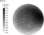
- the portion with the highest flow rate is shifted toward top right, but the flow rate distribution is generally such that the flow rate near the center is higher and the flow rate near the inner wall surface 20a is lower.
- a fungus liquid containing Escherichia coli is caused to flow in a condition in which a lamina flow state like this is produced.
- the survival rate of Escherichia coli contained in the processed fluid was found to be 0.07%.
- the sterilization effect in a laminal flow state is about seven times as great as that of a turbulent flow state.
- the fluid in a laminal flow state is irradiated with ultraviolet light of an intensity distribution corresponding to the flow rate distribution of the laminal flow state. Therefore, the sterilization efficiency for the fluid is improved.
- the inflow port 23 and the light source 40 are positioned on the central axis of the straight tube 20 so that a smooth flow of the fluid is created in the direction of irradiation with the ultraviolet light from the light source 40.
- the inflow port 23 at a position opposite to the light source 40, the fluid that is made less turbulent and turned into a laminal flow state by traveling in the straight tube 20 is irradiated with ultraviolet light with a great intensity.
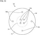
- Fig. 10 is a front view schematically showing a configuration of a light source 140 according to a variation.
- the light source 140 includes a plurality of light emitting devices 142a, 142b, and a substrate 144.
- the light source 140 includes a plurality of first light emitting devices 142a positioned close to each other in a central region C1 of the substrate 144 and a plurality of second light emitting devices 142b scattered in a peripheral region C2 of the substrate 144.
- the first light emitting devices 142a and the second light emitting devices 142b are configured similarly to the light emitting device 42 described above.
- the light source 140 Since the first light emitting devices 142a are positioned close to each other in the central region C1, the light source 140 outputs ultraviolet light of a relatively high intensity in the central region C1. Meanwhile, the second light emitting devices 142b are positioned sparsely in the peripheral region C2 so that the light source 140 outputs ultraviolet light of a relatively low intensity in the peripheral region C2. Therefore, by applying the light source 140 according to this variation to the fluid sterilization apparatus 10 described above, the fluid can be irradiated with ultraviolet light having an ultraviolet light intensity in which the ultraviolet light intensity is higher near the center and the ultraviolet light intensity is lower near the inner wall surface 20a even when the diameter d of the straight tube 20 is increased to increase the processing volume.
- Figs. 11 and 12 are cross-sectional views schematically showing a configuration of a fluid sterilization apparatus 210 according to the second embodiment, and Fig. 12 shows an A-A cross section of Fig. 11 .
- the fluid sterilization apparatus 210 includes a straight tube 220, an inflow pipe 231, an outflow pipe 232, a plurality of first light sources 240a, and a plurality of second light sources 240b.
- the fluid sterilization apparatus 210 differs from the first embodiment in that the inflow pipe 231 and the outflow pipe 232 are positioned on the central axis of the straight tube 220, thereby forming a straight flow passage 212 instead of an L-shaped flow passage.
- a description will be given of this embodiment, highlighting difference from the first embodiment.
- the straight tube 220 extends from the first end 221 to the second end 222.
- the first end 221 is provided with a first end face 221a perpendicular to the longitudinal direction of the straight tube 220 and an inflow port 223 positioned near the center of the first end face 221a.
- the first end face 221a is provided with a plurality of first windows 227 for transmitting the ultraviolet light from the first light source 240a.
- the inflow pipe 231 extending in the longitudinal direction of the straight tube 220 is fitted to the inflow port 223.
- the inflow pipe 231 causes the fluid to flow in in the longitudinal direction of the straight tube 220 and inhibits turbulence from being produced in the flow in the flow passage 212.
- the second end 222 is configured similarly to the first end 221.
- the second end 222 is provided with a second end face 222a perpendicular to the longitudinal direction of the straight tube 220 and an outflow port 224 positioned near the center of the second end face 222a.
- the second end face 222a is provided with a plurality of second windows 228 for transmitting the ultraviolet light from the second light source 240b.
- the outflow pipe 232 extending in the longitudinal direction of the straight tube 220 is fitted to the outflow port 224.
- the outflow pipe 232 causes the fluid to flow in in the longitudinal direction of the straight tube 220 and inhibits turbulence from being produced in the flow in the flow passage 212.
- the first light sources 240a include a plurality of first light emitting devices 242a and a plurality of first substrates 244a. As shown in Fig. 12 , the plurality of first light emitting devices 242a are positioned in four directions to surround the inflow port 223 and mounted to the first substrates 244a. Each of the plurality of first light emitting devices 242a emits ultraviolet light toward the interior of the straight tube 220 in the longitudinal direction of the straight tube 220 via the associated first window 227.
- the first light emitting devices 242a are provided at four locations but the first light emitting devices 242a may be provided in three or fewer locations or in five or more locations. It is preferable that the plurality of first light emitting devices 242a be arranged at regular intervals so as to irradiate the entire fluid flowing in the flow passage 212. By positioning the first light emitting devices 242a at regular intervals so as to surround the inflow port 223, the first light sources 240a are capable of radiating ultraviolet light in a light intensity distribution in which the ultraviolet light intensity is higher near the center of the straight tube 220 and the ultraviolet light intensity is lower near the inner wall surface 220a of the straight tube 220.
- the second light sources 240b include a plurality of second light emitting devices 242b and a plurality of second substrates 244ab and configured similarly to the first light sources 240a.
- the plurality of second light emitting devices 242b are positioned in four directions to surround the outflow port 224 and mounted to the second substrates 244b.
- Each of the plurality of second light emitting devices 242b emits ultraviolet light toward the interior of the straight tube 220 in the longitudinal direction of the straight tube 220 via the associated second window 228.
- the second light sources 240b radiate ultraviolet light in a light intensity distribution in which the ultraviolet light intensity is higher near the center of the straight tube 220 and the ultraviolet light intensity is lower near the inner wall surface 220a of the straight tube 220.
- the inner diameter of the straight tube 220 and the average flow rate of the fluid flowing in the flow passage 112 are adjusted so that the fluid flowing in the flow passage 212 is in a laminal flow state.
- the fluid having such a flow rate distribution is irradiated with ultraviolet light from the first light sources 240a and the second light sources 240b of an intensity distribution in which the ultraviolet intensity near the center of the straight tube 220 is higher and the ultraviolet intensity near the inner wall surface 220a is lower.
- the sterilization efficiency for the fluid is improved by irradiating the fluid in a laminal flow state with ultraviolet light of an intensity distribution corresponding to the flow rate distribution of the laminal flow state.
- the inflow port 223 and the outflow port 224 are positioned on the central axis of the straight tube 220. Therefore, turbulence and eddies are inhibited from being produced in the fluid flowing in the flow passage 212. Since the light sources 240a, 240b are positioned at both the inflow port 223 and the outflow port 224, the amount of ultraviolet energy affecting the fluid is increased as compared to the case of irradiating the fluid with ultraviolet light from only one port so that the sterilization efficiency for the fluid is improved.
- the light source may be positioned only at one of the inflow port 223 and the outflow port 224.
- the light sources 240a and 240b may be provided in the interior of the straight tube 220. Where the light sources 240a and 240b are provided in the interior of the straight tube 220, the light sources 240a and 240b are attached to the end faces 221a and 222b of the straight tube 220, and a cover member that transmit ultraviolet light is provided so as to prevent the light sources from being in direct contact with the fluid flowing in the flow passage 212.
- the fluid sterilization apparatus 10 is described as a apparatus for irradiating the fluid with ultraviolet light so as to sterilize the fluid.
- the inventive fluid sterilization apparatus may be used for a purification process for decomposing organic substance included in a fluid by using ultraviolet irradiation.
- a straightener may not be provided in the middle of the above-described flow passage formed by the straight tube, and, more specifically, at the inflow port or at a position upstream of the inflow port.
- the straightener may have a function of straightening the flow of the fluid flowing in the flow passage and turning the fluid into a laminal flow.
- the light source may be provided with an adjusting mechanism for adjusting the intensity distribution of ultraviolet light emitted by the light emitting device.
- the adjusting mechanism may include a transmissive optical element such as a lens or a reflective optical element such as a concave mirror.
- the adjusting mechanism may configure the intensity distribution of the ultraviolet light output from the light source to correspond to the flow rate distribution of the laminal state by adjusting the intensity distribution of the ultraviolet light from the light emitting device.
- the fluid sterilization apparatus 10 can be used for sterilization of a variety of types of fluid other than the cutting fluid for machine tools, culture fluid for hydroponic culture, and Japanese sake.
- proliferation of bacteria that affect the growth of fish adversely is prevented by sterilizing water in a water tank for keeping fish in an aquarium, farm, and home.
- cleaning sheets used in hospitals, accommodation facilities, homes, etc. such that the sheets are sterilized along with the cleaning liquid, pathogenic bacteria can be killed, and infection is prevented from spreading.
- the detergent for dishwashers, skin lotion, and the like contains aromatic compounds in the form of effective ingredients
- bathwater in circulating hot water bath contains sebum components from human bodies in large amounts, but the fluid sterilization apparatus 10 according to the embodiment can sterilize these types of fluid efficiently.
- 10 ... fluid sterilization apparatus, 12 ... flow passage, 20 ... straight tube, 21 ... first end, 22 ... second end, 23 ... inflow port, 24 ... outflow port, 40 ... light source, 42 ... light emitting device, 140 ... light source, 210 ... fluid sterilization apparatus, 212 ... flow passage, 220 ... straight tube, 221 ... first end, 222 ... second end, 223 ... inflow port, 224 ... outflow port, 240a ... first light source, 240b ... second light source
- the present invention can be used in a fluid sterilization apparatus for sterilizing a fluid by irradiating the fluid with ultraviolet light.
Landscapes
- Life Sciences & Earth Sciences (AREA)
- Engineering & Computer Science (AREA)
- Chemical & Material Sciences (AREA)
- Health & Medical Sciences (AREA)
- Organic Chemistry (AREA)
- Wood Science & Technology (AREA)
- Zoology (AREA)
- Food Science & Technology (AREA)
- General Health & Medical Sciences (AREA)
- Polymers & Plastics (AREA)
- Bioinformatics & Cheminformatics (AREA)
- General Engineering & Computer Science (AREA)
- Genetics & Genomics (AREA)
- Biochemistry (AREA)
- Environmental Sciences (AREA)
- Toxicology (AREA)
- Animal Behavior & Ethology (AREA)
- Veterinary Medicine (AREA)
- Public Health (AREA)
- Epidemiology (AREA)
- Botany (AREA)
- Physics & Mathematics (AREA)
- Nutrition Science (AREA)
- Fluid Mechanics (AREA)
- Mechanical Engineering (AREA)
- Apparatus For Disinfection Or Sterilisation (AREA)
- Physical Water Treatments (AREA)
- Food Preservation Except Freezing, Refrigeration, And Drying (AREA)
- Alcoholic Beverages (AREA)
- Distillation Of Fermentation Liquor, Processing Of Alcohols, Vinegar And Beer (AREA)
- Hydroponics (AREA)
- Auxiliary Devices For Machine Tools (AREA)
Abstract
Description
- The present invention relates to fluid sterilization apparatus and fluid sterilization methods and, more particularly, to a technology of sterilizing a fluid by irradiating the fluid with ultraviolet light.
- It is known that ultraviolet light has sterilization capability. Devices that radiate ultraviolet light are used for sterilization in medical and food processing fronts. Devices that sterilize a fluid such as water continuously by irradiating the fluid with ultraviolet light are also used (see, for example, patent documents 1-3).
- [patent document 1]
JP4-264199 - [patent document 2]
JP2012-24880 - [patent document 3]
JP9-163884 - In related-art fluid sterilization devices, the fluid is irradiated with ultraviolet light of a wavelength of 254 nm emitted from a low-pressure mercury lamp. As pointed out in the patent documents above, the ultraviolet light of this wavelength is absorbed by the fluid itself and only reaches the depth of several millimeters from the surface. Patent document 1 teaches providing a part in the fluid circulation channel where the fluid runs shallow and irradiating the fluid passing through that part with ultraviolet light. This does not, however, provide a radical solution to the issue. A technology for further improving the efficiency of sterilizing a fluid by ultraviolet irradiation is called for.
- In this background, one illustrative purpose of the present invention is to provide a technology capable of improving the efficiency of sterilizing a fluid with ultraviolet light.
- The fluid sterilization apparatus according to an embodiment comprises: a flow passage for causing a fluid to flow; and a light source that irradiates the fluid flowing in the flow passage with ultraviolet light of a wavelength of 290∼310 nm.
- According to this embodiment, it is possible, as described below, to inhibit absorption of ultraviolet light by components contained in the fluid and allow the depth of the fluid to be irradiated with ultraviolet light, thereby killing bacteria and viruses contained in the fluid efficiently.
- The fluid may contain an aromatic compound. Even in the case of a fluid containing aromatic compounds absorptive of ultraviolet light near 254 nm, bacteria and viruses contained in the fluid are efficiently killed by irradiating the fluid with ultraviolet light of a wavelength of 290∼310 nm.
- The flow passage may include a straight tube extending in a longitudinal direction. The fluid may flow in the flow passage in a laminal flow state. The light source may include a light emitting device that emits ultraviolet light of a wavelength of 290∼310 nm and radiate ultraviolet light in an intensity distribution in which an ultraviolet light intensity near a center in a cross section of the flow passage perpendicular to the longitudinal direction is higher than an ultraviolet light intensity around.
- According to this embodiment, the fluid flowing in a laminal flow state is irradiated with ultraviolet light so that the sterilization efficiency is improved as compared to the case of irradiating the fluid in a turbulent state with ultraviolet light. Our knowledge shows that the sterilization efficiency in a laminal flow state is about seven times as great as that of a turbulent flow state in the case of irradiating the interior of a flow passage of a straight tube shape with ultraviolet light for sterilization. Since a fluid in a laminal flow state has a flow rate distribution in which the flow rate near the center is higher and the flow rate near the tube wall is lower, the fluid flowing in the flow passage is irradiated effectively with ultraviolet light and the sterilization efficiency is improved, by increasing the ultraviolet light intensity near the center in association with the flow rate distribution.
- The fluid may contain a cutting fluid for a cutting work. According to this embodiment, bacteria floating in the air are prevented from proliferating, when dissolved in the cutting fluid during a cutting work, on culture media of organic components contained in the cutting fluid.
- The fluid may contain a culture fluid for hydroponic culture. According to this embodiment, pathogenic bacteria mixed in a culture fluid for hydroponic culture are prevented from proliferating and causing the plant to perish.
- The fluid may contain Japanese sake in the process of manufacturing. According to this embodiment, lactic acid bacteria that survive the manufacturing step of Japanese sake are prevented from fermenting the sugar contained in Japanese sake and impairing the original taste of Japanese sake.
- Another embodiment of the present invention relates to a fluid sterilization method. The method comprises: irradiating a fluid flowing in a flow passage with ultraviolet light of a wavelength of 290∼310 nm.
- According to this embodiment, it is equally possible to inhibit absorption of ultraviolet light by components contained in the fluid and allow the depth of the fluid to be irradiated with ultraviolet light, thereby killing bacteria and viruses contained in the fluid efficiently.
- According to the present invention, the efficiency of sterilizing a fluid with ultraviolet light is improved.
-
-
Fig. 1 shows an example of transmission spectrum of a cutting fluid exemplifying a fluid; -
Fig. 2 shows absorption spectra of benzene, naphthalene, and anthracene by way of example of organic compounds having a conjugate double bond; -
Fig. 3 shows absorption spectra of phenol and p-nitrophenol exemplifying aromatic compounds having a functional group, along with an absorption spectrum of benzene; -
Fig. 4 shows an example of transmission spectrum of Japanese sake exemplifying a fluid; -
Fig. 5 shows an example of wavelength dependence of sterilization effect by ultraviolet light; -
Fig. 6 is a cross-sectional view schematically showing a configuration of a fluid sterilization apparatus according to the first embodiment; -
Fig. 7 is a contour figure showing an ultraviolet light intensity distribution in the flow passage; -
Fig. 8 is a contour figure showing a flow rate distribution of a fluid in a turbulent state; -
Fig. 9 is a contour figure showing a flow rate distribution of a fluid in a laminal flow state; -
Fig. 10 is a front view schematically showing a configuration of a light source according to a variation; -
Fig. 11 is a cross-sectional view schematically showing a configuration of a fluid sterilization apparatus according to the second embodiment; and -
Fig. 12 is a cross-sectional view schematically showing a configuration of the fluid sterilization apparatus ofFig. 11 . - The fluid sterilization apparatus according to an embodiment irradiates a fluid with ultraviolet light of a relatively long wavelength (e.g., wavelength in a range of 290∼310 nm) instead of ultraviolet light of a wavelength near 254 nm, which is used in related-art fluid sterilization devices. This inhibits absorption of ultraviolet light by components contained in the fluid and allows the depth of the fluid to be irradiated with ultraviolet light, thereby killing bacteria and viruses contained in the fluid efficiently. A description will be given of the reason why ultraviolet of a wavelength in the range of 290∼310 nm should be radiated.
- In machine tools such as a turning machine, a coolant containing ethylene glycol as a main component is widely used as a cutting fluid. The coolant has a function of a lubricant and a cooling agent at a working point. The inevitable rise in the temperature of the coolant itself with use creates an environment in which bacteria floating in the air are prone, when dissolved in the coolant, to proliferate on culture media of organic components contained in the coolant. As a result, a terrible smell is given off during work especially in summer, resulting in a poor working environment. Components produced by bacteria lower the pH of the fluid and cause rust or corrosion of the worked product and working machine, causing problems like quality loss and reduced life of the working machine. Growth of mold in the cutting fluid is also a serious problem. Growth of mold results in adhesion of deposited material on the wall of the liquid tank. The deposited material inhibits the performance of the coolant and, particularly, lowers the performance of the filtering system. Use of a disinfectant for fungus to control the growth of mold may lead to a change in the cutting performance and so is not preferable especially in a working machine in which high accuracy is required. For this reason, sterilization of the cutting fluid with ultraviolet light is called for.
- In hydroponic culture and plant factories, a culture fluid necessary for growth is circulated. Often, the culture fluid is infiltrated by pathogenic bacteria. Once pathogenic bacteria are mixed in the culture fluid, the plant may perish totally because the culture fluid is circulated. In vegetable cultivation, pesticides are often used to combat diseases. In the case of hydroponic culture, however, pesticides, if used, are dissolved in the culture fluid and contaminate the inner part of the plant. Therefore, most pesticides are unsuitable for use in hydroponic culture. For this reason, sterilization of the culture fluid with ultraviolet light is called for.
- Japanese sake is an alcoholic beverage made by fermenting rice with koji. Lactic acid bacteria that survive the manufacturing step ferment the sugar contained in Japanese sake rapidly, with the result that the original taste of Japanese sake is significantly impaired. For this reason, a step called "hi-i-ire", whereby koji contained in the fermented, unprocessed sake is removed by a filter, and the filtered sake is then processed at a temperature of about 60°, is performed in the production of Japanese sake. Lactic acid bacteria are killed in this step. However, "hi-i-re" is known to impair the rich flavor and taste that Japanese sake has. Attempts are therefore made to prevent the flavor from being deteriorated by using a low temperature, shorten the time or the like. Therefore, lactic acid bacteria may remain in very rare circumstances. In that case, lactic acid bacteria proliferate before the product reaches the consumer via a distribution channel. By the time a consumer opens the bottle, the sake will contain a carbon dioxide gas and turn into an acetic taste. The phenomenon is called "hi-ochi". Killing of lactic acid bacteria with ultraviolet light makes "hi-i-re" unnecessary and is believed to make it possible to manufacture Japanese sake of mallow taste in which the flavor and taste are not impaired.
-
Fig. 1 shows an example of transmission spectrum of a cutting fluid exemplifying a fluid. The transmission spectrum is measured by using a commercially available cutting fluid. The spectrum shows that transmittance of ultraviolet light of a wavelength less than about 290 nm is as low as 15% or below but ultraviolet light of a wavelength of about 290 nm or more is transmitted without being absorbed as much. Such transmission property is considered to derive from absorption of ultraviolet light below about 290 nm by the following organic compounds added to the cutting fluid.


- All these organic compounds contain a benzene ring, and it is considered that the presence of conjugate double bonds shifts the wavelength of absorbed ultraviolet light toward the longer wavelength side with the result that ultraviolet light of a wavelength up to about 290 nm is absorbed.
- It is well known that with the increase in conjugate double bonds, the wavelength of absorbed ultraviolet light is shifted toward the longer wavelength side.
Fig. 2 shows absorption spectra of benzene, naphthalene, and anthracene by way of example of organic compounds having a conjugate double bond. The rising edge of absorption is shifted to near 270 nm in the case of benzene, about 310 nm in the case of naphthalene, and 390 nm in the case of anthracene. Further, the wavelength of ultraviolet light absorbed is also affected by the functional group bonded to the benzene ring.Fig. 3 shows absorption spectra of phenol and p-nitrophenol exemplifying aromatic compounds having a functional group, along with an absorption spectrum of benzene. The hydroxyl group and nitro group shift absorption in phenol and p-nitrophenol more toward the longer wavelength side than in the case of benzene. - The fluid such as a cutting fluid contains aromatic compounds as additives or impurities. Aromatic compounds are generally highly absorptive of ultraviolet light of a wavelength near 254 nm. Therefore, most of ultraviolet light of a wavelength near 254 nm irradiating the fluid will be absorbed by aromatic compounds near the surface of the fluid.
- By way of contrast, ultraviolet light of a wavelength longer than 254 nm, and, for example, 290 nm or longer, is hardly absorbed by benzene, naphthalene, or phenol.
-
Fig. 4 shows an example of transmission spectrum of Japanese sake. The graph shows transmission spectra of two kinds of commercially available Japanese sake and purified water. In each Japanese sake, hardly any light is transmitted in a wavelength region shorter than 285 nm. This is considered to be because Japanese sake contains phenol in an amount of about 10 ppm∼300 ppm and a large amount of aromatic amino acids so that these aromatic compounds absorb most of ultraviolet light of a wavelength less than 285 nm. -
Fig. 5 shows an example of wavelength dependence of sterilization effect by ultraviolet light. Nucleic acids in bacteria and viruses are said to absorb ultraviolet light of a wavelength near 260 nm efficiently as shown in the figure. Therefore, as described above, related-art fluid sterilization devices are configured to irradiate the fluid with ultraviolet light of a wavelength near 254 nm. As shown in the graph, however, ultraviolet light of longer wavelengths is expected to provide sterilization effect given that the wavelength is up to about 310 nm. Ultraviolet light in this range is less effective than ultraviolet light of a wavelength near 254 nm. However, the deficiency can be cured by increasing the light amount or time of irradiation. For example, a fluid can be sterilized properly by irradiating it with ultraviolet light of a wavelength of, for example, 290∼310 nm. The sterilization effect by irradiation with ultraviolet light of a wavelength of near 290 nm is about 30%, meaning a drop of about 1/3 from the case of irradiation with ultraviolet light of a wavelength near 254 nm characterized by the greatest sterilization effect. However, the equivalent sterilization effect can be obtained by increasing the ultraviolet irradiation energy about three times. This is a sufficiently practical value in terms of application to the fluid sterilization apparatus. - As described above, it is preferable to radiate ultraviolet light of a wavelength of 290 nm or longer in order to reduce absorption of ultraviolet light by aromatic compounds contained in the fluid subject to sterilization, and it is preferable to radiate ultraviolet light of a wavelength of 310 nm or shorter in order to kill bacteria or viruses contained in the fluid effectively.
- The upper limit value may be selected in accordance with the types of organic compounds contained in the fluid. For example, ultraviolet light of a wavelength of 270 nm or longer may be used if the main component is benzene and the other aromatic compounds are contained in very little amount. Ultraviolet light of a wavelength of 270 nm or longer may also be used in the case where the main component is anthracene. If the main component is naphthalene or phenol, it is preferable to use ultraviolet light of a wavelength of 290 nm or longer. If the main component is p-nitrophenol, on the other hand, it is preferable to use ultraviolet light of a wavelength of 300 nm or shorter, and, more preferably, 280 nm or shorter. The absorption spectrum of the fluid subject to sterilization may be measured beforehand to determine the wavelength of ultraviolet light that should be radiated. In this case, the permitted absorption level of the fluid may be determined in consideration of the amount of ultraviolet light radiated, duration of irradiation, irradiation energy, and depth of the channel at the position of ultraviolet irradiation, and the wavelength of ultraviolet light radiated may be determined based on the absorption level thus determined.
- The upper limit value may be selected in accordance with the types of bacteria and viruses contained in the fluid. For example, if bacteria and viruses for which ultraviolet light of a longer wavelength than the example shown in
Fig. 5 is effective are contained in the fluid, ultraviolet light of a wavelength longer than 310 nm may be used. For example, the upper limit value may be 320 nm, 330 nm, 340 nm, or 350 nm. In this case, too, the types of bacteria and viruses contained in the fluid subject to sterilization may be examined beforehand and the wavelength of ultraviolet light may be determined based on the types of bacteria and viruses contained. - The light source for irradiating the fluid with ultraviolet light of the wavelength discussed above is exemplified by a xenon lamp, deuterium lamp, and light emitting diode. A xenon lamp and a deuterium lamp emit light of wavelengths other than the wavelength(s) discussed above and make it necessary to use a filter to prevent the temperature of the fluid from increasing due to the heat ray. Accordingly, it is preferable to use a light emitting diode capable of emitting ultraviolet light of the wavelength discussed above selectively. A description will now be given of a configuration of a fluid sterilization apparatus in which a light emitting diode is used as a light source. Like numerals are used in the description to denote like elements and the description is omitted as appropriate.
-
Fig. 6 schematically shows a configuration of afluid sterilization apparatus 10 according to the first embodiment. Thefluid sterilization apparatus 10 includes astraight tube 20, anoutflow pipe 30, and alight source 40. Thelight source 40 is positioned at an end (second end 22) of thestraight tube 20 and radiates ultraviolet light toward the interior of thestraight tube 20. Thefluid sterilization apparatus 10 is used to irradiate a fluid (water etc.) flowing in thestraight tube 20 with ultraviolet light so as to sterilize the fluid. - The
straight tube 20 includes afirst end 21, asecond end 22, a first flange 36, and awindow 28. Thestraight tube 20 extends from thefirst end 21 to thesecond end 22 in the longitudinal direction. Thefirst end 21 is provided with aninflow port 23 for causing the fluid to flow in in the longitudinal direction of thestraight tube 20 and afirst flange 26 for connecting theinflow port 23 to another pipe, etc. Awindow 28 for transmitting the ultraviolet light from thelight source 40 is provided on thesecond end 22. Thewindow 28 is made of a material having a high ultraviolet transmittance such as quartz (SiO2), sapphire (Al2O3), and amorphous fluororesin. - The
second end 22 is provided with anoutflow port 24 for causing the fluid to flow out in a direction intersecting or perpendicular to the longitudinal direction of thestraight tube 20. Theoutflow port 24 is provided on the side wall of thestraight tube 20, and anoutflow pipe 30 is fitted to theoutflow pipe 30. One end of theoutflow pipe 30 is fitted to theoutflow port 24, and asecond flange 32 is provided at the other end. Therefore, thestraight tube 20 and theoutflow pipe 30 form an L-shapedflow passage 12. The fluid flowing in via thefirst flange 26 flows through theinflow port 23, thestraight tube 20, theoutflow port 24, and theoutflow pipe 30 before flowing out via thesecond flange 32. - The
straight tube 20 and theoutflow pipe 30 are made of a metal material or a resin material. Aninner wall surface 20a of thestraight tube 20 is desirably made of a material having a high ultraviolet reflectivity. For example, theinner wall surface 20a is made of mirror-polished aluminum (Al) or polytetrafluoroethylene (PTFE), which is a fully fluorinated resin. By forming theinner wall surface 20a of thestraight tube 20 using a material like the above, the ultraviolet light emitted by thelight source 40 can be reflected by theinner wall surface 20a to propagate in the longitudinal direction of thestraight tube 20. PTFE is a chemically stable material and has a high ultraviolet reflectivity and so is suitable as the material of thestraight tube 20 forming the fluid sterilization apparatus. - The inner diameter d of the
straight tube 20 and the average flow rate v of the fluid flowing in theflow passage 12 are adjusted so that the fluid flowing in theflow passage 12 is in a laminal flow state. More specifically, the inner diameter d and the average flow rate v are adjusted such that the Reynolds number Re of theflow passage 12 is equal to or less than the critical Reynolds number of the laminal flow, using an expression Re=v∗d/v(v: dynamic coefficient of viscosity). The value equal to or less than the critical Reynolds number means that the Reynolds number Re is 3000 or less, and, preferably, 2500 or less, and more preferably, 2320 or less. Further, by causing the fluid to flow from theinflow port 23 into theflow passage 12 in the longitudinal direction, the fluid is caused to flow toward thesecond end 22 in a laminal flow state. When the fluid flows in a laminal flow state, the flow rate distribution is such that the flow rate v1 of the fluid flowing near the central axis of thestraight tube 20 is relatively high and the flow rate v2 of the fluid flowing near theinner wall surface 20a of thestraight tube 20 is relatively low. In an ideal laminal flow state, the fluid flowing in theflow passage 12 presents a flow rate distribution given by an expression of a paraboloid of revolution. - The
light source 40 includes alight emitting device 42 and asubstrate 44. Thelight emitting device 42 is a light emitting diode (LEDs) configured to emit ultraviolet light, and the central wavelength or peak wavelength thereof is included in a range of about 200 nm∼350 nm. It is preferable that thelight emitting device 42 emit ultraviolet light in the aforementioned wavelength range (e.g., near 290 nm∼310 nm). Such an ultraviolet LED is exemplified by an aluminum gallium nitride (AlGaN) based LED. - The
light emitting device 42 is an LED having a predetermined directivity angle or light distribution angle. For example, thelight emitting device 42 is a wide light-distribution LED characterized by a light distribution angle (full-angle value) of 120° or more. Thelight emitting device 42 with such a specification is exemplified by an LED of a surface mount device (SMD) type characterized by a high output intensity. Thelight emitting device 42 is arranged on the central axis of thestraight tube 20 and is fitted to thesubstrate 44 so as to face thewindow 28. Thesubstrate 44 is made by using a highly exoergic member. For example, copper (Cu), aluminum (Al), or the like is used as a base material. The heat generated by thelight emitting device 42 is dissipated via thesubstrate 44. -
Fig. 7 is a contour figure showing an ultraviolet light intensity distribution in theflow passage 12. Since thelight emitting device 42 emits ultraviolet light having a predetermined light distribution angle, the intensity distribution is such that the ultraviolet light intensity near the center is higher than the ultraviolet light intensity around. As a result, the ultraviolet light intensity distribution in thestraight tube 20 is such that the ultraviolet light intensity near the central axis is higher and the ultraviolet light intensity near theinner wall surface 20a is lower in a cross-sectional view of theflow passage 12 perpendicular to the longitudinal direction. - With the above features, the
fluid sterilization apparatus 10 irradiates the fluid flowing in thestraight tube 20 with ultraviolet light to sterilize the fluid. The ultraviolet light from thelight source 40 is radiated such that the intensity is higher near the center of thestraight tube 20 and lower near theinner wall surface 20a of thestraight tube 20. The fluid is caused to flow in theflow passage 12 such that the flow rate v1 near the center is higher and the flow rate v2 near theinner wall surface 20a is lower. As a result, a laminal flow state is produced so that the amount of energy of ultraviolet light affecting the fluid passing through thestraight tube 20 is uniformized regardless of the radial position where the fluid passes. This allows the entire fluid flowing in thestraight tube 20 to be irradiated with ultraviolet of a predetermined amount of energy or higher and enhances the sterilization effect on the entire fluid. - A description will now be given of the advantage of the
fluid sterilization apparatus 10 with reference to a comparative example.Fig. 8 is a contour figure showing a flow rate distribution of a fluid in a turbulent state and shows a flow rate distribution occurring when the fluid is caused to flow in thestraight tube 20 in a condition in which the Reynolds number Re=4961. In the illustrated example, the flow rate in some portions near theinner wall surface 20a is the highest, and the flow rate near the center is of a negative value. The flow rate distribution of the fluid is not constant and changes with time. A fungus liquid containing Escherichia coli is caused to flow in a condition in which a turbulent flow state like this is produced. The survival rate of Escherichia coli contained in the processed fluid was found to be 0.53%. -
Fig. 9 is a contour figure showing a flow rate distribution of a fluid in a laminal flow state and shows a flow rate distribution occurring when the fluid is caused to flow in thestraight tube 20 in a condition in which the Reynolds number Re=2279. In the illustrated example, the portion with the highest flow rate is shifted toward top right, but the flow rate distribution is generally such that the flow rate near the center is higher and the flow rate near theinner wall surface 20a is lower. A fungus liquid containing Escherichia coli is caused to flow in a condition in which a lamina flow state like this is produced. The survival rate of Escherichia coli contained in the processed fluid was found to be 0.07%. These results reveal that the sterilization effect in a laminal flow state is about seven times as great as that of a turbulent flow state. Thus, according to this embodiment, the fluid in a laminal flow state is irradiated with ultraviolet light of an intensity distribution corresponding to the flow rate distribution of the laminal flow state. Therefore, the sterilization efficiency for the fluid is improved. - In accordance with this embodiment, the
inflow port 23 and thelight source 40 are positioned on the central axis of thestraight tube 20 so that a smooth flow of the fluid is created in the direction of irradiation with the ultraviolet light from thelight source 40. By providing theinflow port 23 at a position opposite to thelight source 40, the fluid that is made less turbulent and turned into a laminal flow state by traveling in thestraight tube 20 is irradiated with ultraviolet light with a great intensity. This can inhibit unevenness in the amount of ultraviolet energy radiated, created as a portion of the fluid passes through a location where the ultraviolet light intensity is low at a high speed or a portion of the fluid is turned into a stagnant eddy at a location where the ultraviolet light intensity is high, and inhibit the associated impact of lower sterilization effect. -
Fig. 10 is a front view schematically showing a configuration of alight source 140 according to a variation. Thelight source 140 includes a plurality of light emittingdevices substrate 144. Thelight source 140 includes a plurality of firstlight emitting devices 142a positioned close to each other in a central region C1 of thesubstrate 144 and a plurality of secondlight emitting devices 142b scattered in a peripheral region C2 of thesubstrate 144. The firstlight emitting devices 142a and the secondlight emitting devices 142b are configured similarly to thelight emitting device 42 described above. - Since the first
light emitting devices 142a are positioned close to each other in the central region C1, thelight source 140 outputs ultraviolet light of a relatively high intensity in the central region C1. Meanwhile, the secondlight emitting devices 142b are positioned sparsely in the peripheral region C2 so that thelight source 140 outputs ultraviolet light of a relatively low intensity in the peripheral region C2. Therefore, by applying thelight source 140 according to this variation to thefluid sterilization apparatus 10 described above, the fluid can be irradiated with ultraviolet light having an ultraviolet light intensity in which the ultraviolet light intensity is higher near the center and the ultraviolet light intensity is lower near theinner wall surface 20a even when the diameter d of thestraight tube 20 is increased to increase the processing volume. -
Figs. 11 and12 are cross-sectional views schematically showing a configuration of afluid sterilization apparatus 210 according to the second embodiment, andFig. 12 shows an A-A cross section ofFig. 11 . Thefluid sterilization apparatus 210 includes astraight tube 220, aninflow pipe 231, anoutflow pipe 232, a plurality offirst light sources 240a, and a plurality of secondlight sources 240b. Thefluid sterilization apparatus 210 differs from the first embodiment in that theinflow pipe 231 and theoutflow pipe 232 are positioned on the central axis of thestraight tube 220, thereby forming astraight flow passage 212 instead of an L-shaped flow passage. A description will be given of this embodiment, highlighting difference from the first embodiment. - The
straight tube 220 extends from thefirst end 221 to thesecond end 222. Thefirst end 221 is provided with afirst end face 221a perpendicular to the longitudinal direction of thestraight tube 220 and aninflow port 223 positioned near the center of thefirst end face 221a. Thefirst end face 221a is provided with a plurality offirst windows 227 for transmitting the ultraviolet light from thefirst light source 240a. Theinflow pipe 231 extending in the longitudinal direction of thestraight tube 220 is fitted to theinflow port 223. Theinflow pipe 231 causes the fluid to flow in in the longitudinal direction of thestraight tube 220 and inhibits turbulence from being produced in the flow in theflow passage 212. - The
second end 222 is configured similarly to thefirst end 221. Thesecond end 222 is provided with asecond end face 222a perpendicular to the longitudinal direction of thestraight tube 220 and anoutflow port 224 positioned near the center of thesecond end face 222a. Thesecond end face 222a is provided with a plurality ofsecond windows 228 for transmitting the ultraviolet light from the secondlight source 240b. Theoutflow pipe 232 extending in the longitudinal direction of thestraight tube 220 is fitted to theoutflow port 224. Theoutflow pipe 232 causes the fluid to flow in in the longitudinal direction of thestraight tube 220 and inhibits turbulence from being produced in the flow in theflow passage 212. - The
first light sources 240a include a plurality of firstlight emitting devices 242a and a plurality offirst substrates 244a. As shown inFig. 12 , the plurality of firstlight emitting devices 242a are positioned in four directions to surround theinflow port 223 and mounted to thefirst substrates 244a. Each of the plurality of firstlight emitting devices 242a emits ultraviolet light toward the interior of thestraight tube 220 in the longitudinal direction of thestraight tube 220 via the associatedfirst window 227. - In the illustrated example, the first
light emitting devices 242a are provided at four locations but the firstlight emitting devices 242a may be provided in three or fewer locations or in five or more locations. It is preferable that the plurality of firstlight emitting devices 242a be arranged at regular intervals so as to irradiate the entire fluid flowing in theflow passage 212. By positioning the firstlight emitting devices 242a at regular intervals so as to surround theinflow port 223, thefirst light sources 240a are capable of radiating ultraviolet light in a light intensity distribution in which the ultraviolet light intensity is higher near the center of thestraight tube 220 and the ultraviolet light intensity is lower near theinner wall surface 220a of thestraight tube 220. - The second
light sources 240b include a plurality of secondlight emitting devices 242b and a plurality of second substrates 244ab and configured similarly to thefirst light sources 240a. The plurality of secondlight emitting devices 242b are positioned in four directions to surround theoutflow port 224 and mounted to thesecond substrates 244b. Each of the plurality of secondlight emitting devices 242b emits ultraviolet light toward the interior of thestraight tube 220 in the longitudinal direction of thestraight tube 220 via the associatedsecond window 228. Like thefirst light sources 240a, the secondlight sources 240b radiate ultraviolet light in a light intensity distribution in which the ultraviolet light intensity is higher near the center of thestraight tube 220 and the ultraviolet light intensity is lower near theinner wall surface 220a of thestraight tube 220. - The inner diameter of the
straight tube 220 and the average flow rate of the fluid flowing in the flow passage 112 are adjusted so that the fluid flowing in theflow passage 212 is in a laminal flow state. This results in a flow rate distribution in which the flow rate of the fluid flowing near the central axis of thestraight tube 220 is relatively high and the flow rate of the fluid flowing near theinner wall surface 220a of thestraight tube 220 is relatively low. The fluid having such a flow rate distribution is irradiated with ultraviolet light from thefirst light sources 240a and the secondlight sources 240b of an intensity distribution in which the ultraviolet intensity near the center of thestraight tube 220 is higher and the ultraviolet intensity near theinner wall surface 220a is lower. Thus, according to this embodiment, as in the case of the first embodiment, the sterilization efficiency for the fluid is improved by irradiating the fluid in a laminal flow state with ultraviolet light of an intensity distribution corresponding to the flow rate distribution of the laminal flow state. - In further accordance with this embodiment, the
inflow port 223 and theoutflow port 224 are positioned on the central axis of thestraight tube 220. Therefore, turbulence and eddies are inhibited from being produced in the fluid flowing in theflow passage 212. Since thelight sources inflow port 223 and theoutflow port 224, the amount of ultraviolet energy affecting the fluid is increased as compared to the case of irradiating the fluid with ultraviolet light from only one port so that the sterilization efficiency for the fluid is improved. - In one variation, the light source may be positioned only at one of the
inflow port 223 and theoutflow port 224. Thelight sources straight tube 220. Where thelight sources straight tube 220, thelight sources straight tube 220, and a cover member that transmit ultraviolet light is provided so as to prevent the light sources from being in direct contact with the fluid flowing in theflow passage 212. - Described above is an explanation based on an exemplary embodiment. The embodiment is intended to be illustrative only and it will be understood by those skilled in the art that various design changes are possible and various modifications are possible and that such modifications are also within the scope of the present invention.
- The
fluid sterilization apparatus 10 according to the embodiments is described as a apparatus for irradiating the fluid with ultraviolet light so as to sterilize the fluid. In one variation, the inventive fluid sterilization apparatus may be used for a purification process for decomposing organic substance included in a fluid by using ultraviolet irradiation. - In another variation, a straightener may not be provided in the middle of the above-described flow passage formed by the straight tube, and, more specifically, at the inflow port or at a position upstream of the inflow port. The straightener may have a function of straightening the flow of the fluid flowing in the flow passage and turning the fluid into a laminal flow. By providing the straightener, a laminal flow state characterized by less turbulence is formed to enhance the sterilization effect.
- In one variation, the light source may be provided with an adjusting mechanism for adjusting the intensity distribution of ultraviolet light emitted by the light emitting device. The adjusting mechanism may include a transmissive optical element such as a lens or a reflective optical element such as a concave mirror. The adjusting mechanism may configure the intensity distribution of the ultraviolet light output from the light source to correspond to the flow rate distribution of the laminal state by adjusting the intensity distribution of the ultraviolet light from the light emitting device. By providing such an adjusting mechanism, the fluid is irradiated with ultraviolet light of an intensity distribution suitable for a mode of flow of the fluid and the sterilization efficiency is further enhanced.
- The
fluid sterilization apparatus 10 according to the embodiments can be used for sterilization of a variety of types of fluid other than the cutting fluid for machine tools, culture fluid for hydroponic culture, and Japanese sake. For example, proliferation of bacteria that affect the growth of fish adversely is prevented by sterilizing water in a water tank for keeping fish in an aquarium, farm, and home. Further, by cleaning sheets used in hospitals, accommodation facilities, homes, etc. such that the sheets are sterilized along with the cleaning liquid, pathogenic bacteria can be killed, and infection is prevented from spreading. Also, the detergent for dishwashers, skin lotion, and the like contains aromatic compounds in the form of effective ingredients, and bathwater in circulating hot water bath contains sebum components from human bodies in large amounts, but thefluid sterilization apparatus 10 according to the embodiment can sterilize these types of fluid efficiently. - 10 ... fluid sterilization apparatus, 12 ... flow passage, 20 ... straight tube, 21 ... first end, 22 ... second end, 23 ... inflow port, 24 ... outflow port, 40 ... light source, 42 ... light emitting device, 140 ... light source, 210 ... fluid sterilization apparatus, 212 ... flow passage, 220 ... straight tube, 221 ... first end, 222 ... second end, 223 ... inflow port, 224 ... outflow port, 240a ... first light source, 240b ... second light source
- The present invention can be used in a fluid sterilization apparatus for sterilizing a fluid by irradiating the fluid with ultraviolet light.
Claims (7)
- A fluid sterilization apparatus comprising:a flow passage for causing a fluid to flow; anda light source that irradiates the fluid flowing in the flow passage with ultraviolet light of a wavelength of 290∼310 nm.
- The fluid sterilization apparatus according to claim 1, wherein
the fluid contains an aromatic compound. - The fluid sterilization apparatus according to claim 1 or 2, wherein
the flow passage includes a straight tube extending in a longitudinal direction,
the fluid flows in the flow passage in a laminal flow state, and
the light source includes a light emitting device that emits ultraviolet light of a wavelength of 290∼310 nm and radiates ultraviolet light in an intensity distribution in which an ultraviolet light intensity near a center in a cross section of the flow passage perpendicular to the longitudinal direction is higher than an ultraviolet light intensity around. - The fluid sterilization apparatus according to any one of claims 1 through 3, wherein
the fluid contains a cutting fluid for a cutting work. - The fluid sterilization apparatus according to any one of claims 1 through 3, wherein
the fluid contains a culture fluid for hydroponic culture. - The fluid sterilization apparatus according to any one of claims 1 through 3, wherein
the fluid contains Japanese sake in the process of manufacturing. - A fluid sterilization method comprising:
irradiating a fluid flowing in a flow passage with ultraviolet light of a wavelength of 290∼310 nm.
Applications Claiming Priority (2)
| Application Number | Priority Date | Filing Date | Title |
|---|---|---|---|
| JP2016001235A JP6559577B2 (en) | 2016-01-06 | 2016-01-06 | Fluid sterilization apparatus and fluid sterilization method |
| PCT/JP2016/081422 WO2017119174A1 (en) | 2016-01-06 | 2016-10-24 | Fluid sterilization device and fluid sterilization method |
Publications (2)
| Publication Number | Publication Date |
|---|---|
| EP3511024A1 true EP3511024A1 (en) | 2019-07-17 |
| EP3511024A4 EP3511024A4 (en) | 2020-06-24 |
Family
ID=59274518
Family Applications (1)
| Application Number | Title | Priority Date | Filing Date |
|---|---|---|---|
| EP16883674.0A Withdrawn EP3511024A4 (en) | 2016-01-06 | 2016-10-24 | FLUID STERILIZATION DEVICE AND METHOD |
Country Status (4)
| Country | Link |
|---|---|
| US (1) | US20180310498A1 (en) |
| EP (1) | EP3511024A4 (en) |
| JP (1) | JP6559577B2 (en) |
| WO (1) | WO2017119174A1 (en) |
Families Citing this family (8)
| Publication number | Priority date | Publication date | Assignee | Title |
|---|---|---|---|---|
| US11312642B2 (en) | 2017-03-31 | 2022-04-26 | Industrial Technology Research Institute | Fluid sterilizing device |
| JP6892788B2 (en) * | 2017-05-26 | 2021-06-23 | ウシオ電機株式会社 | Sterilization method, sterilization equipment |
| JP6885279B2 (en) * | 2017-09-22 | 2021-06-09 | 東芝ライテック株式会社 | Fluid sterilizer |
| PL237378B1 (en) * | 2018-04-03 | 2021-04-06 | Univ Przyrodniczy W Lublinie | Device for sterilization of plant material |
| PL237377B1 (en) * | 2018-04-03 | 2021-04-06 | Univ Przyrodniczy W Lublinie | Device for sterilization of plant material |
| CN113041373B (en) * | 2021-04-29 | 2023-09-08 | 北京航天三发高科技有限公司 | Cutting fluid ultraviolet disinfection device and disinfection efficiency determination method thereof |
| KR20230052772A (en) * | 2021-10-13 | 2023-04-20 | 엘지전자 주식회사 | Plants cultivation apparatus |
| WO2024153723A1 (en) | 2023-01-19 | 2024-07-25 | Unilever Ip Holdings B.V. | Water purification using high intensity narrow spectrum light |
Family Cites Families (24)
| Publication number | Priority date | Publication date | Assignee | Title |
|---|---|---|---|---|
| JPH03212332A (en) * | 1989-10-13 | 1991-09-17 | Mitsubishi Heavy Ind Ltd | Liquid sterilizing method and apparatus by ultraviolet ray |
| JPH04264199A (en) * | 1991-02-18 | 1992-09-18 | Yushiro Chem Ind Co Ltd | Method for sterilizing water-soluble metal working oil by ultraviolet light |
| US5626768A (en) * | 1995-12-07 | 1997-05-06 | Triton Thalassic Technologies, Inc. | Sterilization of opaque liquids with ultraviolet radiation |
| JPH09163884A (en) * | 1995-12-19 | 1997-06-24 | Iwasaki Electric Co Ltd | Hydroponics UV water sterilizer |
| GB0117571D0 (en) * | 2001-07-19 | 2001-09-12 | Common Services Agency | UV irradiation control |
| JP2004201535A (en) * | 2002-12-24 | 2004-07-22 | Kyushu Kankyo Techno Kk | A method for producing a brewed food having excellent storage stability and flavor, and an apparatus for sterilizing a fermented brewed food used in the method |
| US8986607B2 (en) * | 2003-02-27 | 2015-03-24 | Baxter International Inc. | Method for the validatable inactivation of pathogens in a biological fluid by irradiation |
| US7993580B2 (en) * | 2004-08-24 | 2011-08-09 | Baxter International Inc. | Methods for the inactivation of microorganisms in biological fluids, flow through reactors and methods of controlling the light sum dose to effectively inactivate microorganisms in batch reactors |
| JP2007003062A (en) * | 2005-05-26 | 2007-01-11 | Matsushita Electric Ind Co Ltd | refrigerator |
| DE102005062410A1 (en) * | 2005-12-23 | 2007-08-09 | Forschungsgemeinschaft Der Drk-Blutspendedienste E.V. | Method for irradiating platelet concentrates in flexible containers with ultraviolet light |
| KR100971177B1 (en) * | 2010-04-07 | 2010-07-20 | (주)유브이플러스 | Ultraviolet rays sterilizer for fruid having poor ultraviolet rays transmission |
| JP2012024880A (en) | 2010-07-22 | 2012-02-09 | Honda Motor Co Ltd | Ultraviolet sterilization device method |
| JP5632903B2 (en) * | 2012-12-06 | 2014-11-26 | 日機装株式会社 | Light irradiation device |
| EP3461793B1 (en) * | 2013-01-24 | 2022-03-02 | Atlantium Technologies Ltd. | Method and apparatus for liquid disinfection by light emitted from light emitting diodes |
| JP2014233646A (en) * | 2013-05-30 | 2014-12-15 | 日機装株式会社 | Water purifier |
| HUE035031T2 (en) * | 2014-07-11 | 2018-05-02 | Vicente Fidel Salas | System and method for sterilizing fluid |
| JP6486249B2 (en) * | 2015-09-07 | 2019-03-20 | 日機装株式会社 | Sterilizer |
| JP6571460B2 (en) * | 2015-09-07 | 2019-09-04 | 日機装株式会社 | Sterilizer |
| JP6549456B2 (en) * | 2015-09-25 | 2019-07-24 | 日機装株式会社 | Fluid sterilizer |
| JP2017064610A (en) * | 2015-09-29 | 2017-04-06 | 日機装株式会社 | Irradiation device and liquid sterilization method |
| JP2017074114A (en) * | 2015-10-13 | 2017-04-20 | 日機装株式会社 | Fluid sterilizer and fluid sterilization method |
| JP6629569B2 (en) * | 2015-11-04 | 2020-01-15 | 日機装株式会社 | Fluid sterilizer |
| JP6710139B2 (en) * | 2016-10-11 | 2020-06-17 | 日機装株式会社 | Sterilizer |
| JP2018148938A (en) * | 2017-03-09 | 2018-09-27 | 日機装株式会社 | Fluid sterilizer |
-
2016
- 2016-01-06 JP JP2016001235A patent/JP6559577B2/en active Active
- 2016-10-24 WO PCT/JP2016/081422 patent/WO2017119174A1/en not_active Ceased
- 2016-10-24 EP EP16883674.0A patent/EP3511024A4/en not_active Withdrawn
-
2018
- 2018-07-03 US US16/026,628 patent/US20180310498A1/en not_active Abandoned
Also Published As
| Publication number | Publication date |
|---|---|
| US20180310498A1 (en) | 2018-11-01 |
| JP2017121319A (en) | 2017-07-13 |
| JP6559577B2 (en) | 2019-08-14 |
| EP3511024A4 (en) | 2020-06-24 |
| WO2017119174A1 (en) | 2017-07-13 |
Similar Documents
| Publication | Publication Date | Title |
|---|---|---|
| US20180310498A1 (en) | Fluid sterilization apparatus and fluid sterilization method | |
| US20180228928A1 (en) | Fluid sterilization device and fluid sterilization method | |
| EP2965766B1 (en) | System and method for sterilizing a fluid | |
| CN111107749A (en) | Photobioreactor for cold pasteurization of liquid foods and use of said reactor | |
| JP2014233712A (en) | Ultraviolet sterilization device | |
| JP2008510538A (en) | Biological liquid, method for inactivating microorganisms in flow reactors and method for controlling total dose to effectively inactivate microorganisms in batch reactors | |
| JP2015033669A (en) | UV sterilizer | |
| US20130248459A1 (en) | Cuvette apparatus and method | |
| US20090294688A1 (en) | Ultraviolet Radiation Treatment System | |
| RU2676618C2 (en) | Recipient with variable geometry for uv water purification | |
| JP2015062902A (en) | Liquid sterilization method and apparatus | |
| WO2012044264A1 (en) | Method for the cold sterilization and pasteurization of opaque, translucent or transparent liquids | |
| JP2000107262A (en) | Sterilization method by photoirradiation | |
| CN111032577A (en) | water treatment equipment | |
| JP7054104B2 (en) | pH adjustment method and aquaculture method | |
| CN106565043A (en) | Red-nose scissors fish self-purifying aquaculture system | |
| Guerrero-Beltran et al. | Ultraviolet-C light processing of liquid food products | |
| US20240260597A1 (en) | Systems and Method for Removing the Yellow Color of Riboflavin from Lactose Solutions | |
| KR20210044773A (en) | Process fluid treatment system and method for deactivating undesirable organisms | |
| Koutchma | Non-‐thermal and non-‐chemical UV Purification Achieves Better Safety and Quality of Food and Drink Ingredients | |
| JP7447442B2 (en) | Sterilization method | |
| JPS5821559B2 (en) | Sterilization method and equipment | |
| RU2546235C2 (en) | Milk disinfection method | |
| JPWO2018143304A1 (en) | Ultraviolet irradiation module cell and ultraviolet irradiation module | |
| JP2024008165A (en) | Sterilizer |
Legal Events
| Date | Code | Title | Description |
|---|---|---|---|
| STAA | Information on the status of an ep patent application or granted ep patent |
Free format text: STATUS: THE INTERNATIONAL PUBLICATION HAS BEEN MADE |
|
| PUAI | Public reference made under article 153(3) epc to a published international application that has entered the european phase |
Free format text: ORIGINAL CODE: 0009012 |
|
| STAA | Information on the status of an ep patent application or granted ep patent |
Free format text: STATUS: REQUEST FOR EXAMINATION WAS MADE |
|
| 17P | Request for examination filed |
Effective date: 20180803 |
|
| AK | Designated contracting states |
Kind code of ref document: A1 Designated state(s): AL AT BE BG CH CY CZ DE DK EE ES FI FR GB GR HR HU IE IS IT LI LT LU LV MC MK MT NL NO PL PT RO RS SE SI SK SM TR |
|
| A4 | Supplementary search report drawn up and despatched |
Effective date: 20200525 |
|
| RIC1 | Information provided on ipc code assigned before grant |
Ipc: A61L 2/10 20060101AFI20200516BHEP Ipc: C12G 3/02 20190101ALI20200516BHEP Ipc: C12H 1/16 20060101ALI20200516BHEP Ipc: A23L 3/28 20060101ALI20200516BHEP Ipc: A01G 31/00 20180101ALI20200516BHEP Ipc: A23L 2/48 20060101ALI20200516BHEP Ipc: C12H 1/06 20060101ALI20200516BHEP Ipc: B23Q 11/10 20060101ALI20200516BHEP Ipc: A23L 2/50 20060101ALI20200516BHEP |
|
| STAA | Information on the status of an ep patent application or granted ep patent |
Free format text: STATUS: EXAMINATION IS IN PROGRESS |
|
| 17Q | First examination report despatched |
Effective date: 20221014 |
|
| REG | Reference to a national code |
Ref country code: DE Ref legal event code: R079 Free format text: PREVIOUS MAIN CLASS: A61L0002100000 Ipc: C12G0003022000 |
|
| RIC1 | Information provided on ipc code assigned before grant |
Ipc: C12G 3/022 20190101AFI20240502BHEP |
|
| GRAP | Despatch of communication of intention to grant a patent |
Free format text: ORIGINAL CODE: EPIDOSNIGR1 |
|
| STAA | Information on the status of an ep patent application or granted ep patent |
Free format text: STATUS: GRANT OF PATENT IS INTENDED |
|
| INTG | Intention to grant announced |
Effective date: 20240607 |
|
| RIN1 | Information on inventor provided before grant (corrected) |
Inventor name: KIUCHI, HIROKI Inventor name: KONAGAYOSHI, HIDENORI Inventor name: OCHI, TETSUMI Inventor name: ASANO, HIDEKI |
|
| STAA | Information on the status of an ep patent application or granted ep patent |
Free format text: STATUS: THE APPLICATION IS DEEMED TO BE WITHDRAWN |
|
| 18D | Application deemed to be withdrawn |
Effective date: 20241008 |