EP3510732B1 - Bussystem sowie kommunikationsverfahren - Google Patents
Bussystem sowie kommunikationsverfahren Download PDFInfo
- Publication number
- EP3510732B1 EP3510732B1 EP17784541.9A EP17784541A EP3510732B1 EP 3510732 B1 EP3510732 B1 EP 3510732B1 EP 17784541 A EP17784541 A EP 17784541A EP 3510732 B1 EP3510732 B1 EP 3510732B1
- Authority
- EP
- European Patent Office
- Prior art keywords
- bus
- transmitter
- transceiver
- receiver pair
- receiver
- Prior art date
- Legal status (The legal status is an assumption and is not a legal conclusion. Google has not performed a legal analysis and makes no representation as to the accuracy of the status listed.)
- Not-in-force
Links
Images
Classifications
-
- H—ELECTRICITY
- H04—ELECTRIC COMMUNICATION TECHNIQUE
- H04L—TRANSMISSION OF DIGITAL INFORMATION, e.g. TELEGRAPHIC COMMUNICATION
- H04L12/00—Data switching networks
- H04L12/28—Data switching networks characterised by path configuration, e.g. LAN [Local Area Networks] or WAN [Wide Area Networks]
- H04L12/40—Bus networks
- H04L12/40006—Architecture of a communication node
- H04L12/40032—Details regarding a bus interface enhancer
-
- H—ELECTRICITY
- H04—ELECTRIC COMMUNICATION TECHNIQUE
- H04L—TRANSMISSION OF DIGITAL INFORMATION, e.g. TELEGRAPHIC COMMUNICATION
- H04L12/00—Data switching networks
- H04L12/28—Data switching networks characterised by path configuration, e.g. LAN [Local Area Networks] or WAN [Wide Area Networks]
- H04L12/46—Interconnection of networks
- H04L12/4604—LAN interconnection over a backbone network, e.g. Internet, Frame Relay
- H04L12/462—LAN interconnection over a bridge based backbone
- H04L12/4625—Single bridge functionality, e.g. connection of two networks over a single bridge
-
- H—ELECTRICITY
- H04—ELECTRIC COMMUNICATION TECHNIQUE
- H04L—TRANSMISSION OF DIGITAL INFORMATION, e.g. TELEGRAPHIC COMMUNICATION
- H04L12/00—Data switching networks
- H04L12/28—Data switching networks characterised by path configuration, e.g. LAN [Local Area Networks] or WAN [Wide Area Networks]
- H04L12/40—Bus networks
- H04L2012/40208—Bus networks characterized by the use of a particular bus standard
- H04L2012/40215—Controller Area Network CAN
Definitions
- the invention relates to a bus system containing bus lines according to the preamble of claim 1.
- the invention also relates to a method for transmitting data in a bus system according to the preamble of claim 5.
- a bus system with at least two bus lines is known to which a plurality of bus users are each connected via a transceiver.
- the transceiver converts a differential signal on the bus line into a digital signal.
- the bus participant is designed as a microcontroller that has a bus controller. If the bus system is a CAN bus, the microcontroller is connected to the transceiver via a CAN controller.
- the known bus system describes a wired connection between the bus participants and the bus lines. It is desirable that the bus users are connected wirelessly to a bus node or with bus lines. Through this a weight reduction due to the elimination of cables and plug connections would be associated. Furthermore, galvanic isolation would ensure mechanical decoupling of the bus participants.
- bus subscribers are connected to bus lines in a wired manner.
- the bus subscribers each have interface modules that are wirelessly or wirelessly connected to I / O modules for data exchange.
- Corresponding radio modules are required for this.
- the radio modules can be designed as USB Bluetooth modules, RS-232 Bluetooth modules, B-WLAN modules or the like. These are protocol-based radio standards that only allow a radio connection between two different buses, for example CAN buses.
- the other bus participants should not be able to recognize whether the communication takes place via cable or wirelessly.
- a bus system with bus lines is known to which a number of bus users can be connected via a transceiver.
- a microcontroller is connected to the transceiver which is used to convert a CAN signal into a radio signal.
- the disadvantage of the known bus system is that it is not real-time capable due to the protocol implementation.
- the object of the present invention is to specify a system with a bus system and a method for the transmission of data in a bus system in such a way that wireless communication between bus users is made possible in a simple and reliable manner.
- the invention has the features of claim 1.
- the invention provides an intermediate bridge unit which is arranged between a bus participant and a bus node of the bus system, the intermediate bridge unit having at least two transmitter / receiver pairs for bidirectional communication. Transmitters of these transmitter / receiver pairs have a transmitter oscillator, an amplitude and / or phase and / or frequency modulator and a dual-mode antenna. Receivers have a demodulator and an antenna. One transmit / receive pair is connected to the transceiver cable. The other send / receive pair is connected to the bus subscriber cable or to a repeater. According to the invention there is a wireless transmission of digital signals.
- the intermediate bridge unit has no software or protocols.
- the intermediate bridge unit also has no A / D or D / A converters.
- the modulation or demodulation takes place exclusively on the basis of circuit components, digital information being transmitted and preferably frequency division multiplexing taking place.
- the intermediate bridge unit has a first construction module with a first transmitter / receiver pair, which is cable-connected to the transceiver is. Furthermore, the intermediate bridge unit has a second construction module which is connected via a second transmitter / receiver pair to the bus subscriber or to a further repeater or transceiver arranged in a cable-connected manner on a second bus node.
- a bus subscriber can advantageously be connected wirelessly to a bus system or the intermediate bridge unit can also be used as a gateway to another bus system.
- the bus subscriber has a data bus controller, preferably a CAN controller, as the hardware interface. It is advantageous to dispense with a circuit that converts differential signals from the CAN bus into asymmetrical dual-mode signals.
- the transceiver is used as a connection to the bus node, so that standardized digital signals R x (received data) and T x (transmitted data) can be used on a side of the transceiver facing away from the bus.
- the transmitter / receiver pair or the first construction module and the second construction module of the intermediate bridge unit thus connect directly to a transceiver.
- the intermediate bridge unit is designed in such a way that a radio transmission link is formed using two free space modes. In this way, the full transmission capacity of the radio channel can advantageously be used.
- the radio transmission takes place in any frequency range, preferably in the UWB band up to 10 GHz.
- the advantage of using the dual-mode radio is increased security against eavesdropping.
- the method according to the invention has the features of claim 5.
- the particular advantage of the method according to the invention is that radio transmission can be implemented in real time. There is thus a 1: 1 replacement of the cable-connected communication between bus users and bus nodes.
- a system according to the invention comprises in particular a bus system which can be designed, for example, as a CAN bus system, LIN bus system, Flexray bus system, SPI bus system or the like.
- the present exemplary embodiments are limited to a CAN bus system.
- the CAN bus system can be used in the automotive or industrial sector. It enables communication preferably between control devices or I / O devices.
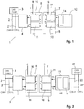
- a CAN bus system 1 has two bus lines 2, 2 '.
- a transceiver 4 is connected by cable to a bus node 3, a first connecting line of the transceiver 4 being connected to the first bus line 2 and a second cable connection of the transceiver 4 being connected to the second bus line 2 'on a side of the transceiver 4 facing the bus.
- an intermediate bridge unit 5 which comprises a first construction module 6 and a second construction module 7.
- the first construction module 6 has a first transmitter / receiver pair 8 and the second construction module 7 has a second transmitter / receiver pair 9.
- the first construction module 6 and the second construction module 7 are wirelessly coupled to one another via a radio link.
- the first building module 6 is connected to the transceiver 4 via a cable connection.
- the transceiver 4 digitizes the differential signals that are present on the bus lines 2, 2 'into the digital signals and transmits them as transmission data T x to a transmitter 10 of the first transmitter / receiver pair 8.
- the transceiver 4 is in for bidirectional communication able to receive received data R x from a receiver 11 of the first transmitter / receiver pair 8.
- the transmitter 10 has a transmission oscillator, an amplitude and / or phase and / or frequency modulator and an antenna designed as a dual-mode antenna.
- the dual-mode antenna is an antenna for two free space modes.
- the receiver 11 has a demodulator containing a mixer and an antenna designed as a dual-mode antenna.
- the dual-mode antenna is an antenna for two free space modes.
- the second transmitter / receiver pair 9 has the same structure as the first transmitter / receiver pair 8. It is connected via lines to a bus user 12, which has a microcontroller and a CAN module 14. Send data T x and receive data R x can thus be exchanged bidirectionally between the bus subscriber 12 and the second transmitter / receiver pair 9.
- the CAN module 14 serves as a hardware interface between the bus subscriber 12 and the second construction module 7.
- the transmitters 10 and the receivers 11 of the first transmitter / receiver pair 8 and of the second transmitter / receiver pair 9 are of identical design.
- a radio transmission link between a transmitter 10 of the first transmitter / receiver pair 8 and a receiver 11 of the second transmitter / receiver pair 9 on the one hand and the transmitter 10 of the second transmitter / receiver pair 9 and the receiver 11 of the first transmitter / Receiver pair 8 on the other hand takes place via at least two free space modes, which is referred to as dual-mode radio.
- the dual-mode radio can be used with all known basic modulation methods, such as amplitude modulation, phase modulation and frequency modulation.
- the transmitter 10 has a monofrequency high-frequency oscillator, which sends a signal with a reference frequency.
- the amplitude of this signal is then modulated, for example by digitally switching it on and off. This is implemented, for example, by a PIN diode switch.
- the amplitude-modulated signal is split into two paths by means of a signal conductor.
- the two amplitude-modulated signals are emitted via a horizontally polarized antenna and a vertical polarized antenna.
- a horizontally polarized antenna and a vertically polarized antenna of the receiver 11 both receive signals and feed them to a multiplier of the mixer.
- the multiplier can be designed as a Gilbert cell, for example.
- the output signals of the multiplier are in the range of twice the frequency and in the IF frequency range. The latter is only determined by the modulation bandwidth.
- a simple low-pass filter only allows the lower frequency range to pass.
- modulation methods such as phase difference modulation (PDM), amplitude-phase-difference modulation (APDM) and frequency-difference modulation (FDM), amplitude-phase-frequency-difference modulation (APFDM) and 4-mode difference modulation (X4DM) are in the EP 1 964 286 B1 and are considered to be disclosed by this application.
- PDM phase difference modulation
- APDM amplitude-phase-difference modulation
- FDM frequency-difference modulation
- X4DM 4-mode difference modulation
- the radio transmission between the first building module 6 and the second building module 7 takes place in a frequency range from 4.2 GHz to 4.8 GHz.
- the intermediate bridge unit 5 is used to generate a gateway function.
- a gateway module 15 containing a transceiver 16 and a repeater 17 is connected to the second transmitter / receiver pair 9 via the cable connection.
- the transceiver 15 is used to connect to a second bus node 23 of another bus system with line 22, 22 '. This allows a CAN radio gateway to be set up between two CAN bus lines 2, 2 'and 22, 22'.
- the two bus nodes 3, 23 can also be connected to one another in a galvanically separated point-to-point connection.
Landscapes
- Engineering & Computer Science (AREA)
- Computer Networks & Wireless Communication (AREA)
- Signal Processing (AREA)
- Small-Scale Networks (AREA)
- Mobile Radio Communication Systems (AREA)
Description
- Die Erfindung betrifft ein Bussystem enthaltend Busleitungen nach dem Oberbegriff des Patentanspruchs 1.
- Die Erfindung betrifft ferner ein Verfahren zur Übertragung von Daten in einem Bussystem nach dem Oberbegriff des Patentanspruchs 5.
- Aus der
DE 101 34 584 A1 ist ein Bussystem mit mindestens zwei Busleitungen bekannt, an dem eine Mehrzahl von Busteilnehmern jeweils über einen Transceiver angeschlossen sind. Der Transceiver wandelt ein an der Busleitung anliegendes differenzielles Signal in ein digitales Signal um. Der Busteilnehmer ist als ein Mikrocontroller ausgebildet, der über einen Bus-Controller verfügt. Handelt es sich bei dem Bussystem um einen CAN-Bus, ist der Mikrocontroller über ein CAN-Controller mit dem Transceiver verbunden. Das bekannte Bussystem beschreibt eine kabelgebundene Verbindung der Busteilnehmer zu den Busleitungen. Wünschenswert ist, dass die Busteilnehmer kabellos zu einem Busknoten bzw. mit Busleitungen verbunden sind. Hierdurch wäre eine Gewichtsreduzierung aufgrund des Wegfalls von Kabeln und Steckverbindungen verbunden. Ferner würde eine galvanische Trennung eine mechanische Entkopplung der Busteilnehmer gewährleistet. - Aus der
EP 1 840 684 A1 ist ein Bussystem bekannt, bei dem Busteilnehmer kabelgebunden an Busleitungen angeschlossen sind. Die Busteilnehmer weisen jeweils Schnittstellenmodule auf, die zum Datenaustausch kabellos bzw. drahtlos mit I/O-Modulen verbunden sind. Hierzu sind entsprechende Funkmodule erforderlich. Die Funkmodule können als USB-Bluetooth-Module, RS-232-Bluetooth-Module, B-WLAN-Module oder dergleichen ausgebildet sein. Es handelt sich dabei um protokollbasierte Funkstandards, die nur eine Funkverbindung zwischen zwei unterschiedlichen Bussen, beispielsweise CAN-Bussen, ermöglichen. Wünschenswert ist es jedoch, dass die Busteilnehmer kabellos und ohne zusätzliche Protokolle in ein Bussystem integriert werden können. Insbesondere sollen die anderen Busteilnehmer nicht erkennen können, ob die Kommunikation über Kabel oder drahtlos erfolgt. Eine 1:1-Ersetzung der Kabelverbindung durch eine drahtlose Kommunikationsverbindung wäre wünschenswert. - Aus der
EP 1 964 286 B1 ist eine Funkübertragungsstrecke bekannt, die Antennen vorsieht, so dass unter Nutzung von mindestens zwei Freiraummodem Datensignale übertragen werden können. Hierdurch kann eine volle Übertragungskapazität des Funkkanals genutzt werden. Der Einsatz in Bussystemen ist nicht vorgesehen. - Aus der Druckschrift KONGEZOS V K ET AL: "Wireless communication between AGVs (autonomous guided vehicles) and the industrial network CAN (controller area network)" ist ein Bussystem mit Busleitungen bekannt, an denen eine Anzahl von Busteilnehmern über einen Transceiver anschließbar sind. An den Transceiver schließt sich ein Mikrokontroller an, der zur Protokollumsetzung eines CAN-Signals in ein Funksignal dient. Nachteilig an dem bekannten Bussystem ist, dass es aufgrund der Protokollumsetzung nicht echtzeitfähig ist.
- Aufgabe der vorliegenden Erfindung ist es, ein System mit einem Bussystem sowie ein Verfahren zur Übertragung von Daten in einem Bussystem derart anzugeben, dass auf einfache und betriebssichere Weise eine drahtlose Kommunikation von Busteilnehmern ermöglicht wird.
- Zur Lösung dieser Aufgabe weist die Erfindung die Merkmale des Patentanspruchs 1 auf.
- Die Erfindung sieht eine Zwischenbrückeneinheit vor, die zwischen einem Busteilnehmer und einem Busknoten des Bussystems angeordnet ist, wobei die Zwischenbrückeneinheit zumindest zwei Sender-/Empfänger-Paare aufweist zur bidirektionalen Kommunikation. Sender dieser Sender-/Empfänger-Paare weisen einen Senderoszillator, einen Amplituden- und/oder Phasenund/oder Frequenzmodulator sowie eine Dual-Mode-Antenne auf. Empfänger weisen einen Demodulator und eine Antenne auf. Das eine Sende-/Empfangs-Paar ist mit dem Transceiverkabel verbunden. Das andere Sende-/Empfangs-Paar ist mit dem Busteilnehmerkabel oder mit einem Repeater verbunden. Nach der Erfindung erfolgt eine kabellose Übertragung von digitalen Signalen. Die Zwischenbrückeneinheit weist keine Software bzw. Protokolle auf. Auch weist die Zwischenbrückeneinheit keine A/D- bzw. D/A-Wandler auf. Die Modulation bzw. Demodulation erfolgt ausschließlich auf Basis von Schaltungskomponenten, wobei digitale Informationen übertragen werden und bevorzugt ein Frequenzmultiplexbetrieb erfolgt.
- Nach der Erfindung weist die Zwischenbrückeneinheit ein erstes Baumodul mit einem ersten Sende-/Empfänger-Paar auf, das mit dem Transceiver kabelverbunden ist. Ferner weist die Zwischenbrückeneinheit ein zweites Baumodul auf, das über eine zweite Sender-/Empfänger-Paar mit dem Busteilnehmer oder mit einem weiteren an einem zweiten Busknoten kabelverbunden angeordneten Repeater bzw. Transceiver verbunden ist. Vorteilhaft kann hierdurch ein Busteilnehmer kabellos an ein Bussystem angeschlossen werden bzw. kann die Zwischenbrückeneinheit auch als ein Gateway zu einem anderen Bussystem genutzt werden.
- Nach der Erfindung weist der Busteilnehmer einen Datenbus-Controller, vorzugsweise einen CAN-Controller, als Hardwareschnittstelle auf. Vorteilhaft wird auf eine Schaltung verzichtet, die differenziellen Signale des CAN-Busses in unsymmetrische Dualmode-Signale umwandelt. Stattdessen wird der Transceiver als Anbindung zu dem Busknoten genutzt, so dass auf einer busabgewandten Seite des Transceivers standardisierte digitale Signale Rx (Empfangsdaten) und Tx (Sendedaten) genutzt werden können. Das Sende-/Empfänger-Paar bzw. das erste Baumodul sowie das zweite Baumodul der Zwischenbrückeneinheit schließen sich somit direkt an einen Transceiver an.
- Nach der Erfindung ist die Zwischenbrückeneinheit derart ausgebildet, dass eine Funkübertragungsstrecke unter Nutzung von zwei Freiraummoden gebildet ist. Vorteilhaft kann hierdurch die volle Übertragungskapazität des Funckanals genutzt werden.
- Nach einer Weiterbildung der Erfindung erfolgt die Funkübertragung in einem beliebigen Frequenzbereich, bevorzugt im UWB-Band bis 10 GHz. Vorteilhaft ist, durch die Verwendung des Dual-Mode Funks, eine erhöhte Abhörsicherheit gegeben.
- Zur Lösung der Aufgabe weist das erfindungsgemäße Verfahren die Merkmale des Patentanspruchs 5 auf.
- Der besondere Vorteil des erfindungsgemäßen Verfahrens besteht darin, dass eine Funkübertragung in Echtzeit realisiert werden kann. Es erfolgt somit eine 1:1-Ersetzung der kabelverbundenen Kommunikation zwischen Busteilnehmern und Busknoten.
- Ausführungsbeispiele der Erfindung werden nachfolgend anhand der Zeichnungen näher erläutert.
- Es zeigen:
- Fig. 1
- ein Blockschaltbild einer ersten Ausführungsform des erfindungsgemäßen Systems und
- Fig. 2
- ein Blockschaltbild einer zweiten Ausführungsform des erfindungsgemäßen Systems.
- Ein erfindungsgemäßes System umfasst insbesondere ein Bussystem, das beispielsweise als ein CAN-Bussystem, LIN-Bussystem, Flexray-Bussystem, SPI-Bussystem oder dergleichen ausgebildet sein kann. In den vorliegenden Ausführungsbeispielen wird sich auf ein CAN-Bussystem beschränkt.
- Das CAN-Bussystem kann im Automobil- oder im Industriebereich eingesetzt werden. Es ermöglicht die Kommunikation vorzugsweise zwischen Steuergeräten bzw. I/O-Geräten.
- Nach einer ersten Ausführungsform der Erfindung weist ein CAN-Bussystem 1 zwei Busleitungen 2, 2' auf. An einem Busknoten 3 ist ein Transceiver 4 kabelgebunden angeschlossen, wobei auf eine dem Bus zugewandten Seite des Transceivers 4 eine erste Verbindungsleitung des Transceivers 4 an der ersten Busleitung 2 und eine zweite Kabelverbindung des Transceivers 4 an der zweiten Busleitung 2' angeschlossen ist.
- Auf einer dem Bus abgewandten Seite des Transceivers 4 schließt sich eine Zwischenbrückeneinheit 5 an, die ein erstes Baumodul 6 und ein zweites Baumodul 7 umfasst. Das erste Baumodul 6 weist ein erstes Sende-/Empfänger-Paar 8 und das zweite Baumodul 7 weist ein zweites Sende-/Empfänger-Paar 9 auf. Das erste Baumodul 6 und das zweite Baumodul 7 sind über eine Funkverbindung drahtlos miteinander gekoppelt.
- Das erste Baumodul 6 ist über eine Kabelverbindung mit dem Transceiver 4 verbunden. Der Transceiver 4 digitalisiert die differenziellen Signale, die auf den Busleitungen 2, 2' anliegen in die digitale Signale und überträgt diese als Sendedaten Tx an einen Sender 10 des ersten Sende-/Empfänger-Paares 8. Zur bidirektionalen Kommunikation ist der Transceiver 4 in der Lage, Empfangsdaten Rx von einem Empfänger 11 des ersten Sende-/Empfänger-Paares 8 zu erhalten.
- Der Sender 10 weist einen Sendeoszillator, einen Amplituden- und/oder Phasen- und/oder Frequenzmodulator sowie eine als Dual-Mode-Antenne ausgebildete Antenne auf. Die Dual-Mode-Antenne ist eine Antenne für zwei Freiraummoden.
- Der Empfänger 11 weist einen Demodulator enthaltend einen Mischer sowie eine als Dual-Mode-Antenne ausgebildete Antenne auf. Die Dual-Mode-Antenne ist eine Antenne für zwei Freiraummoden.
- Das zweite Sende-/Empfänger-Paar 9 weist den gleichen Aufbau auf wie das erste Sende-/Empfänger-Paar 8. Es ist über Leitungen mit einem Busteilnehmer 12 verbunden, der einen Mikrocontroller sowie ein CAN-Modul 14 aufweist. Es sind somit bidirektional Sendedaten Tx und Empfangsdaten Rx zwischen dem Busteilnehmer 12 und dem zweiten Sender-/Empfänger-Paar 9 austauschbar. Das CAN-Modul 14 dient als Hardwareschnittstelle des Busteilnehmers 12 zu dem zweiten Baumodul 7.
- Die Sender 10 und die Empfänger 11 des ersten Sende-/Empfänger-Paares 8 und des zweiten Sende-/Empfänger-Paares 9 sind gleich ausgebildet. Eine Funkübertragungsstrecke zwischen einem Sender 10 des ersten Sende-/Empfänger-Paares 8 und einem Empfänger 11 des zweiten Sende-/Empfänger-Paares 9 einerseits und dem Sender 10 des zweiten Sende-/Empfänger-Paares 9 und dem Empfänger 11 des ersten Sende-/Empfänger-Paares 8 andererseits erfolgt über mindestens zwei Freiraummoden, der als Dual-Mode-Funk bezeichnet wird. Der Dual-Mode-Funk ist bei allen bekannten Grundmodulationsverfahren, wie Amplitudenmodulation, Phasenmodulation und Frequenzmodulation einsetzbar. Bei Anwendung der Amplitudenmodulation weist der Sender 10 einen monofrequenten Hochfrequenzoszillator auf, der ein Signal mit einer Referenzfrequenz sendet. Anschließend wird dieses Signal beispielsweise durch eine digitale Ein- und Ausschaltung in der Amplitude moduliert. Dieses wird beispielsweise durch einen PIN-Diodenschalter realisiert. Das amplitudenmodulierte Signal wird mittels eines Signalleiters in zwei Pfade aufgeteilt. Über eine horizontal polarisierte Antenne und eine vertikale polarisierte Antenne werden die beiden amplitudenmodulierten Signale abgestrahlt. Eine horizontal polarisierte Antenne und eine vertikal polarisierte Antenne des Empfängers 11 empfangen beide Signale und führen diese einem Multiplizierer des Mischers zu. Der Mulitplizierer kann beispielsweise als eine Gilbertzelle ausgebildet sein. Ausgangssignale des Multiplizierers liegen im Bereich der doppelten Frequenz und im ZF-Frequenzbereich. Letzterer wird nur durch die Modulationsbandbreite bestimmt. Ein einfaches Tiefpassfilter lässt nur den unteren Frequenzbereich passieren.
- Weitere Modulationsverfahren, wie beispielsweise Phasen-Differenzmodulation (PDM), Amplituden-Phasen-Differenzmodulation (APDM) und Frequenz-Differenzmodulation (FDM), Amplituden-Phasen-Frequenz-Differenzmodulation (APFDM) sowie 4-Moden-Differenzmodulation (X4DM) sind in der
EP 1 964 286 B1 beschrieben und gelten als durch diese Anmeldung mit offenbart. - Die Funkübertragung zwischen dem ersten Baumodul 6 und dem zweiten Baumodul 7 erfolgt in einem Frequenzbereich von 4,2 GHz bis 4,8 GHz.
- Da im Vergleich zur einer kabelgebundenen Anbindung des Busteilnehmers lediglich zwei Sende-/Empfänger-Paare 8, 9 zwischen dem Transceiver 4 und dem Busteilnehmer 12 zwischengeschaltet werden, kann eine kabellose Verbindung des Busteilnehmers 12 an die Busleitung 2, 2' einfach und kostengünstig hergestellt werden.
- Nach einer zweiten Ausführungsform der Erfindung gemäß
Figur 2 dient die Zwischenbrückeneinheit 5 zur Erzeugung einer Gateway-Funktion. - Gleiche Bauteile bzw. Bauteilfunktionen der Ausführungsbeispiele sind mit den gleichen Bezugsziffern versehen.
- Im Unterschied zu der ersten Ausführungsform ist an das zweite Sende-/Empfänger-Paar 9 ein Gateway-Modul 15 enthaltend ein Transceiver 16 und ein Repeater 17 über die Kabelverbindung angeschlossen. Der Transceiver 15 dient zur Anbindung an einen zweiten Busknoten 23 eines anderen Bussystems mit Leitung 22, 22'. Hierdurch kann ein CAN-Funk-Gateway zwischen zwei CAN-Busleitungen 2, 2' und 22, 22' eingerichtet werden.
- Alternativ können auch die zwei Busknoten 3, 23 in einer galvanisch getrennten Punkt-Zu-Punkt-Verbindung miteinander verbunden werden.
Claims (5)
- Bussystem enthaltend Busleitungen (2, 2'), an denen eine Anzahl von Busteilnehmern (12) oder Gateway-Module (15) über einen Transceiver (4) anschließbar sind, wobei der Transceiver (4) an einem Busknoten (3) kabelgebunden angeschlossen ist, wobei auf einer dem Bus zugewandten Seite des Transceivers (4) eine erste Verbindungsleitung des Transceivers (4) an der ersten Busleitung (2) und eine zweite Kabelverbindung des Transceivers (4) an der zweiten Busleitung (2') angeschlossen ist, dadurch gekennzeichnet,- dass auf einer busabgewandten Seite des Transceivers (4) sich eine Zwischenbrückeneinheit (5) anschließt, die ein erstes Baumodul (6) und ein zweites Baumodul (7) umfasst, wobei das erste Baumodul (6) ein einen Sender (10) und einen Empfänger (11) aufweisendes erstes Sende-/Empfänger-Paar (8) und das zweite Baumodul (7) ein einen Sender (10) und einen Empfänger (11) aufweisendes zweites Sende-/Empfänger-Paar (9) aufweist, wobei das erste Sende-/Empfänger-Paar (8) über eine Funkschnittstelle mit dem zweiten Sende-/Empfänger-Paar (9) unter Nutzung von zwei Freiraummoden gekoppelt ist,- dass der jeweilige Sender (10) einen Senderoszillator, eine Amplitudenund/oder Phasen- und/oder Frequenzmodulator sowie eine DualMode-Antenne aufweist und wobei der jeweilige Empfänger (11) einen Mischer aufweisenden Demodulator sowie eine Dual-Mode-Antenne aufweist,- dass das zweite Sende-/Empfänger-Paar (9) den gleichen Aufbau aufweist wie das erste Sende-/Empfänger-Paar (8),- dass das zweite Sende-/Empfänger-Paar (9) über Leitungen mit einem Busteilnehmer (12) oder einem Gateway-Modul (15) verbunden ist, wobei der Busteilnehmer (12) einen Mikrokontroller und einen Datenbus-Controller (14) und wobei das Gateway-Modul (15) einen Transceiver (16) und einen Repeater (17) aufweist.
- Bussystem nach Anspruch 1, dadurch gekennzeichnet, dass die Zwischenbrückeneinheit (5) nicht protokollbasiert ausgebildet ist.
- Bussystem nach Anspruch 1 oder 2, dadurch gekennzeichnet, dass die Funkübertragung zwischen dem ersten Sende-/Empfänger-Paar (8) und dem zweiten Sende-/Empfänger-Paar (9) in einem Frequenzbereich Im UWB-Band bis 10 GHz erfolgt.
- Bussystem nach einem der Ansprüche 1 bis 3, dadurch gekennzeichnet, dass der Sender (10) nur einen einzigen Sendeoszillator aufweist.
- Verfahren umfassend: Übertragen von Daten von den Busleitungen (2, 2') zu dem Teilnehmer (12) oder zu dem Gateway-Modul (15) in einem Bussystem (1) nach einem der Ansprüche 1 bis 4, oder Übertragen von Daten von dem Teilnehmer (12) oder von dem Gateway-Modul (15) zu den Busleitungen (2, 2') in einem Bussystem (1) nach einem der Ansprüche 1 bis 4.
Applications Claiming Priority (2)
| Application Number | Priority Date | Filing Date | Title |
|---|---|---|---|
| DE102016116599.9A DE102016116599A1 (de) | 2016-09-06 | 2016-09-06 | Bussystem sowie Kommunikationsverfahren |
| PCT/DE2017/100729 WO2018046055A1 (de) | 2016-09-06 | 2017-08-31 | Bussystem sowie kommunikationsverfahren |
Publications (2)
| Publication Number | Publication Date |
|---|---|
| EP3510732A1 EP3510732A1 (de) | 2019-07-17 |
| EP3510732B1 true EP3510732B1 (de) | 2021-10-20 |
Family
ID=60117422
Family Applications (1)
| Application Number | Title | Priority Date | Filing Date |
|---|---|---|---|
| EP17784541.9A Not-in-force EP3510732B1 (de) | 2016-09-06 | 2017-08-31 | Bussystem sowie kommunikationsverfahren |
Country Status (3)
| Country | Link |
|---|---|
| EP (1) | EP3510732B1 (de) |
| DE (1) | DE102016116599A1 (de) |
| WO (1) | WO2018046055A1 (de) |
Family Cites Families (5)
| Publication number | Priority date | Publication date | Assignee | Title |
|---|---|---|---|---|
| DE10134584B4 (de) | 2001-07-17 | 2005-12-08 | Siemens Ag | Bussystem und Verfahren zum Austausch von Daten |
| DE102005061219A1 (de) | 2005-12-20 | 2007-06-21 | Fachhochschule Aachen | Anordnung einer Funkübertagungsstrecke |
| EP1840684A1 (de) | 2006-03-27 | 2007-10-03 | Siemens Aktiengesellschaft | Automatisierungsgerät sowie-system, enthält Automatisierungskomponenten die per lösbaren Funkmodulen drahtlos kommunizieren können |
| US9191263B2 (en) * | 2008-12-23 | 2015-11-17 | Keyssa, Inc. | Contactless replacement for cabled standards-based interfaces |
| US9813004B2 (en) * | 2015-01-16 | 2017-11-07 | Abb Schweiz Ag | Systems and methods concerning exciterless synchronous machines |
-
2016
- 2016-09-06 DE DE102016116599.9A patent/DE102016116599A1/de not_active Ceased
-
2017
- 2017-08-31 WO PCT/DE2017/100729 patent/WO2018046055A1/de not_active Ceased
- 2017-08-31 EP EP17784541.9A patent/EP3510732B1/de not_active Not-in-force
Non-Patent Citations (1)
| Title |
|---|
| None * |
Also Published As
| Publication number | Publication date |
|---|---|
| DE102016116599A1 (de) | 2018-03-08 |
| EP3510732A1 (de) | 2019-07-17 |
| WO2018046055A9 (de) | 2018-07-05 |
| WO2018046055A1 (de) | 2018-03-15 |
Similar Documents
| Publication | Publication Date | Title |
|---|---|---|
| EP2499878B1 (de) | Master-einheit, remote-einheit sowie multiband-übertragungssystem | |
| DE602004000546T2 (de) | Schnelles drahtloses Netzwerk mit erweitertem Abdeckungsgebiet | |
| DE112009001289B4 (de) | Kommunikationsvorrichtung, Kommunikationssystem und Kommunikationsverfahren | |
| EP3360257B1 (de) | Kraftfahrzeug mit mehreren antennen und wenigstens einer zentralen kommunikationseinrichtung | |
| WO2018149459A1 (de) | Kompensator, elektronische schaltungsanordnung zum betreiben einer antenne und antennenvorrichtung | |
| EP2823602B1 (de) | Buskommunikationsvorrichtung | |
| DE10224284A1 (de) | Nutzungsberechtigungskontrollverfahren | |
| DE102009023949A1 (de) | Datenübermittlungsgerät zur Fernüberwachung und-steuerung eines verteilten Prozesssystems | |
| DE69228908T2 (de) | Funksprechgerät bei dem ein Frequenzteiler während des Sendens verwendet und während des Empfangs angehalten wird. | |
| EP2761793A1 (de) | Bussystem | |
| EP1121773B1 (de) | Mobilfunksystem und mobilstation im duplex und semiduplexbetrieb arbeitend | |
| WO2018046055A9 (de) | Bussystem sowie kommunikationsverfahren | |
| DE19907538C2 (de) | Kommunikationssystem | |
| EP4193575B1 (de) | Verfahren zur kommunikation zwischen einem ersten passiven teilnehmer und einem zweiten passiven teilnehmer eines bussystems | |
| DE102010023535B4 (de) | Bordnetzsystem für ein Kraftfahrzeug | |
| DE102014010829B4 (de) | Dachantennenmodul für ein Kraftfahrzeug | |
| DE10360873B4 (de) | Verfahren zum Betreiben eines Terminals, Terminal und Datenbussystem | |
| DE3444361A1 (de) | Datenuebertragungseinrichtung | |
| DE10248245B3 (de) | Anbindung einer Funkverbindung an ein Fahrzeugnetz | |
| DE102017131138A1 (de) | Vorrichtung zum Übermitteln von Daten innerhalb eines Fahrzeugs | |
| DE102015001677B4 (de) | Steuerungseinheit, System und Verfahren zum Senden und Empfangen von Funksignalen in mehreren Frequenzbereichen | |
| DE3149956A1 (de) | Linienfunksystem | |
| DE10220765A1 (de) | Verfahren und Vorrichtung zur Signalübertragung | |
| DE102004008920A1 (de) | Sende- und Empfangsanordnung für TD-SCDMA-Mobilfunkgeräte | |
| DE102018125290A1 (de) | LoRaWAN-Gateway |
Legal Events
| Date | Code | Title | Description |
|---|---|---|---|
| STAA | Information on the status of an ep patent application or granted ep patent |
Free format text: STATUS: UNKNOWN |
|
| STAA | Information on the status of an ep patent application or granted ep patent |
Free format text: STATUS: THE INTERNATIONAL PUBLICATION HAS BEEN MADE |
|
| PUAI | Public reference made under article 153(3) epc to a published international application that has entered the european phase |
Free format text: ORIGINAL CODE: 0009012 |
|
| STAA | Information on the status of an ep patent application or granted ep patent |
Free format text: STATUS: REQUEST FOR EXAMINATION WAS MADE |
|
| 17P | Request for examination filed |
Effective date: 20190411 |
|
| AK | Designated contracting states |
Kind code of ref document: A1 Designated state(s): AL AT BE BG CH CY CZ DE DK EE ES FI FR GB GR HR HU IE IS IT LI LT LU LV MC MK MT NL NO PL PT RO RS SE SI SK SM TR |
|
| AX | Request for extension of the european patent |
Extension state: BA ME |
|
| DAV | Request for validation of the european patent (deleted) | ||
| DAX | Request for extension of the european patent (deleted) | ||
| STAA | Information on the status of an ep patent application or granted ep patent |
Free format text: STATUS: EXAMINATION IS IN PROGRESS |
|
| 17Q | First examination report despatched |
Effective date: 20200422 |
|
| GRAP | Despatch of communication of intention to grant a patent |
Free format text: ORIGINAL CODE: EPIDOSNIGR1 |
|
| STAA | Information on the status of an ep patent application or granted ep patent |
Free format text: STATUS: GRANT OF PATENT IS INTENDED |
|
| INTG | Intention to grant announced |
Effective date: 20210428 |
|
| GRAS | Grant fee paid |
Free format text: ORIGINAL CODE: EPIDOSNIGR3 |
|
| GRAA | (expected) grant |
Free format text: ORIGINAL CODE: 0009210 |
|
| STAA | Information on the status of an ep patent application or granted ep patent |
Free format text: STATUS: THE PATENT HAS BEEN GRANTED |
|
| AK | Designated contracting states |
Kind code of ref document: B1 Designated state(s): AL AT BE BG CH CY CZ DE DK EE ES FI FR GB GR HR HU IE IS IT LI LT LU LV MC MK MT NL NO PL PT RO RS SE SI SK SM TR |
|
| REG | Reference to a national code |
Ref country code: GB Ref legal event code: FG4D Free format text: NOT ENGLISH |
|
| REG | Reference to a national code |
Ref country code: CH Ref legal event code: EP |
|
| REG | Reference to a national code |
Ref country code: IE Ref legal event code: FG4D Free format text: LANGUAGE OF EP DOCUMENT: GERMAN |
|
| REG | Reference to a national code |
Ref country code: DE Ref legal event code: R096 Ref document number: 502017011788 Country of ref document: DE |
|
| REG | Reference to a national code |
Ref country code: AT Ref legal event code: REF Ref document number: 1440844 Country of ref document: AT Kind code of ref document: T Effective date: 20211115 |
|
| REG | Reference to a national code |
Ref country code: LT Ref legal event code: MG9D |
|
| REG | Reference to a national code |
Ref country code: NL Ref legal event code: MP Effective date: 20211020 |
|
| PG25 | Lapsed in a contracting state [announced via postgrant information from national office to epo] |
Ref country code: RS Free format text: LAPSE BECAUSE OF FAILURE TO SUBMIT A TRANSLATION OF THE DESCRIPTION OR TO PAY THE FEE WITHIN THE PRESCRIBED TIME-LIMIT Effective date: 20211020 Ref country code: LT Free format text: LAPSE BECAUSE OF FAILURE TO SUBMIT A TRANSLATION OF THE DESCRIPTION OR TO PAY THE FEE WITHIN THE PRESCRIBED TIME-LIMIT Effective date: 20211020 Ref country code: FI Free format text: LAPSE BECAUSE OF FAILURE TO SUBMIT A TRANSLATION OF THE DESCRIPTION OR TO PAY THE FEE WITHIN THE PRESCRIBED TIME-LIMIT Effective date: 20211020 Ref country code: BG Free format text: LAPSE BECAUSE OF FAILURE TO SUBMIT A TRANSLATION OF THE DESCRIPTION OR TO PAY THE FEE WITHIN THE PRESCRIBED TIME-LIMIT Effective date: 20220120 |
|
| PG25 | Lapsed in a contracting state [announced via postgrant information from national office to epo] |
Ref country code: IS Free format text: LAPSE BECAUSE OF FAILURE TO SUBMIT A TRANSLATION OF THE DESCRIPTION OR TO PAY THE FEE WITHIN THE PRESCRIBED TIME-LIMIT Effective date: 20220220 Ref country code: SE Free format text: LAPSE BECAUSE OF FAILURE TO SUBMIT A TRANSLATION OF THE DESCRIPTION OR TO PAY THE FEE WITHIN THE PRESCRIBED TIME-LIMIT Effective date: 20211020 Ref country code: PT Free format text: LAPSE BECAUSE OF FAILURE TO SUBMIT A TRANSLATION OF THE DESCRIPTION OR TO PAY THE FEE WITHIN THE PRESCRIBED TIME-LIMIT Effective date: 20220221 Ref country code: PL Free format text: LAPSE BECAUSE OF FAILURE TO SUBMIT A TRANSLATION OF THE DESCRIPTION OR TO PAY THE FEE WITHIN THE PRESCRIBED TIME-LIMIT Effective date: 20211020 Ref country code: NO Free format text: LAPSE BECAUSE OF FAILURE TO SUBMIT A TRANSLATION OF THE DESCRIPTION OR TO PAY THE FEE WITHIN THE PRESCRIBED TIME-LIMIT Effective date: 20220120 Ref country code: NL Free format text: LAPSE BECAUSE OF FAILURE TO SUBMIT A TRANSLATION OF THE DESCRIPTION OR TO PAY THE FEE WITHIN THE PRESCRIBED TIME-LIMIT Effective date: 20211020 Ref country code: LV Free format text: LAPSE BECAUSE OF FAILURE TO SUBMIT A TRANSLATION OF THE DESCRIPTION OR TO PAY THE FEE WITHIN THE PRESCRIBED TIME-LIMIT Effective date: 20211020 Ref country code: HR Free format text: LAPSE BECAUSE OF FAILURE TO SUBMIT A TRANSLATION OF THE DESCRIPTION OR TO PAY THE FEE WITHIN THE PRESCRIBED TIME-LIMIT Effective date: 20211020 Ref country code: GR Free format text: LAPSE BECAUSE OF FAILURE TO SUBMIT A TRANSLATION OF THE DESCRIPTION OR TO PAY THE FEE WITHIN THE PRESCRIBED TIME-LIMIT Effective date: 20220121 Ref country code: ES Free format text: LAPSE BECAUSE OF FAILURE TO SUBMIT A TRANSLATION OF THE DESCRIPTION OR TO PAY THE FEE WITHIN THE PRESCRIBED TIME-LIMIT Effective date: 20211020 |
|
| REG | Reference to a national code |
Ref country code: DE Ref legal event code: R097 Ref document number: 502017011788 Country of ref document: DE |
|
| PG25 | Lapsed in a contracting state [announced via postgrant information from national office to epo] |
Ref country code: SM Free format text: LAPSE BECAUSE OF FAILURE TO SUBMIT A TRANSLATION OF THE DESCRIPTION OR TO PAY THE FEE WITHIN THE PRESCRIBED TIME-LIMIT Effective date: 20211020 Ref country code: SK Free format text: LAPSE BECAUSE OF FAILURE TO SUBMIT A TRANSLATION OF THE DESCRIPTION OR TO PAY THE FEE WITHIN THE PRESCRIBED TIME-LIMIT Effective date: 20211020 Ref country code: RO Free format text: LAPSE BECAUSE OF FAILURE TO SUBMIT A TRANSLATION OF THE DESCRIPTION OR TO PAY THE FEE WITHIN THE PRESCRIBED TIME-LIMIT Effective date: 20211020 Ref country code: EE Free format text: LAPSE BECAUSE OF FAILURE TO SUBMIT A TRANSLATION OF THE DESCRIPTION OR TO PAY THE FEE WITHIN THE PRESCRIBED TIME-LIMIT Effective date: 20211020 Ref country code: DK Free format text: LAPSE BECAUSE OF FAILURE TO SUBMIT A TRANSLATION OF THE DESCRIPTION OR TO PAY THE FEE WITHIN THE PRESCRIBED TIME-LIMIT Effective date: 20211020 Ref country code: CZ Free format text: LAPSE BECAUSE OF FAILURE TO SUBMIT A TRANSLATION OF THE DESCRIPTION OR TO PAY THE FEE WITHIN THE PRESCRIBED TIME-LIMIT Effective date: 20211020 |
|
| PLBE | No opposition filed within time limit |
Free format text: ORIGINAL CODE: 0009261 |
|
| STAA | Information on the status of an ep patent application or granted ep patent |
Free format text: STATUS: NO OPPOSITION FILED WITHIN TIME LIMIT |
|
| 26N | No opposition filed |
Effective date: 20220721 |
|
| PG25 | Lapsed in a contracting state [announced via postgrant information from national office to epo] |
Ref country code: AL Free format text: LAPSE BECAUSE OF FAILURE TO SUBMIT A TRANSLATION OF THE DESCRIPTION OR TO PAY THE FEE WITHIN THE PRESCRIBED TIME-LIMIT Effective date: 20211020 |
|
| PGFP | Annual fee paid to national office [announced via postgrant information from national office to epo] |
Ref country code: IT Payment date: 20220831 Year of fee payment: 6 Ref country code: GB Payment date: 20220824 Year of fee payment: 6 |
|
| PG25 | Lapsed in a contracting state [announced via postgrant information from national office to epo] |
Ref country code: SI Free format text: LAPSE BECAUSE OF FAILURE TO SUBMIT A TRANSLATION OF THE DESCRIPTION OR TO PAY THE FEE WITHIN THE PRESCRIBED TIME-LIMIT Effective date: 20211020 |
|
| PGFP | Annual fee paid to national office [announced via postgrant information from national office to epo] |
Ref country code: FR Payment date: 20220822 Year of fee payment: 6 |
|
| PG25 | Lapsed in a contracting state [announced via postgrant information from national office to epo] |
Ref country code: MC Free format text: LAPSE BECAUSE OF FAILURE TO SUBMIT A TRANSLATION OF THE DESCRIPTION OR TO PAY THE FEE WITHIN THE PRESCRIBED TIME-LIMIT Effective date: 20211020 |
|
| REG | Reference to a national code |
Ref country code: CH Ref legal event code: PL |
|
| PG25 | Lapsed in a contracting state [announced via postgrant information from national office to epo] |
Ref country code: LU Free format text: LAPSE BECAUSE OF NON-PAYMENT OF DUE FEES Effective date: 20220831 Ref country code: LI Free format text: LAPSE BECAUSE OF NON-PAYMENT OF DUE FEES Effective date: 20220831 Ref country code: CH Free format text: LAPSE BECAUSE OF NON-PAYMENT OF DUE FEES Effective date: 20220831 |
|
| REG | Reference to a national code |
Ref country code: BE Ref legal event code: MM Effective date: 20220831 |
|
| PG25 | Lapsed in a contracting state [announced via postgrant information from national office to epo] |
Ref country code: IE Free format text: LAPSE BECAUSE OF NON-PAYMENT OF DUE FEES Effective date: 20220831 |
|
| PG25 | Lapsed in a contracting state [announced via postgrant information from national office to epo] |
Ref country code: BE Free format text: LAPSE BECAUSE OF NON-PAYMENT OF DUE FEES Effective date: 20220831 |
|
| REG | Reference to a national code |
Ref country code: AT Ref legal event code: MM01 Ref document number: 1440844 Country of ref document: AT Kind code of ref document: T Effective date: 20220831 |
|
| PG25 | Lapsed in a contracting state [announced via postgrant information from national office to epo] |
Ref country code: AT Free format text: LAPSE BECAUSE OF NON-PAYMENT OF DUE FEES Effective date: 20220831 |
|
| PGFP | Annual fee paid to national office [announced via postgrant information from national office to epo] |
Ref country code: DE Payment date: 20231031 Year of fee payment: 7 |
|
| PG25 | Lapsed in a contracting state [announced via postgrant information from national office to epo] |
Ref country code: HU Free format text: LAPSE BECAUSE OF FAILURE TO SUBMIT A TRANSLATION OF THE DESCRIPTION OR TO PAY THE FEE WITHIN THE PRESCRIBED TIME-LIMIT; INVALID AB INITIO Effective date: 20170831 |
|
| GBPC | Gb: european patent ceased through non-payment of renewal fee |
Effective date: 20230831 |
|
| PG25 | Lapsed in a contracting state [announced via postgrant information from national office to epo] |
Ref country code: CY Free format text: LAPSE BECAUSE OF FAILURE TO SUBMIT A TRANSLATION OF THE DESCRIPTION OR TO PAY THE FEE WITHIN THE PRESCRIBED TIME-LIMIT Effective date: 20211020 |
|
| PG25 | Lapsed in a contracting state [announced via postgrant information from national office to epo] |
Ref country code: MK Free format text: LAPSE BECAUSE OF FAILURE TO SUBMIT A TRANSLATION OF THE DESCRIPTION OR TO PAY THE FEE WITHIN THE PRESCRIBED TIME-LIMIT Effective date: 20211020 |
|
| PG25 | Lapsed in a contracting state [announced via postgrant information from national office to epo] |
Ref country code: TR Free format text: LAPSE BECAUSE OF FAILURE TO SUBMIT A TRANSLATION OF THE DESCRIPTION OR TO PAY THE FEE WITHIN THE PRESCRIBED TIME-LIMIT Effective date: 20211020 |
|
| PG25 | Lapsed in a contracting state [announced via postgrant information from national office to epo] |
Ref country code: GB Free format text: LAPSE BECAUSE OF NON-PAYMENT OF DUE FEES Effective date: 20230831 |
|
| PG25 | Lapsed in a contracting state [announced via postgrant information from national office to epo] |
Ref country code: IT Free format text: LAPSE BECAUSE OF NON-PAYMENT OF DUE FEES Effective date: 20230831 Ref country code: GB Free format text: LAPSE BECAUSE OF NON-PAYMENT OF DUE FEES Effective date: 20230831 Ref country code: FR Free format text: LAPSE BECAUSE OF NON-PAYMENT OF DUE FEES Effective date: 20230831 |
|
| PG25 | Lapsed in a contracting state [announced via postgrant information from national office to epo] |
Ref country code: MT Free format text: LAPSE BECAUSE OF FAILURE TO SUBMIT A TRANSLATION OF THE DESCRIPTION OR TO PAY THE FEE WITHIN THE PRESCRIBED TIME-LIMIT Effective date: 20211020 |
|
| REG | Reference to a national code |
Ref country code: DE Ref legal event code: R119 Ref document number: 502017011788 Country of ref document: DE |
|
| PG25 | Lapsed in a contracting state [announced via postgrant information from national office to epo] |
Ref country code: DE Free format text: LAPSE BECAUSE OF NON-PAYMENT OF DUE FEES Effective date: 20250301 |