EP3510717B1 - Verfahren und vorrichtung zum senden und empfangen von übertragungsschemen mit mehrfachen timing in drahtlosem zellularem kommunikationssystem - Google Patents
Verfahren und vorrichtung zum senden und empfangen von übertragungsschemen mit mehrfachen timing in drahtlosem zellularem kommunikationssystem Download PDFInfo
- Publication number
- EP3510717B1 EP3510717B1 EP17861079.6A EP17861079A EP3510717B1 EP 3510717 B1 EP3510717 B1 EP 3510717B1 EP 17861079 A EP17861079 A EP 17861079A EP 3510717 B1 EP3510717 B1 EP 3510717B1
- Authority
- EP
- European Patent Office
- Prior art keywords
- terminal
- transmission
- transmission type
- base station
- search space
- Prior art date
- Legal status (The legal status is an assumption and is not a legal conclusion. Google has not performed a legal analysis and makes no representation as to the accuracy of the status listed.)
- Active
Links
- 230000005540 biological transmission Effects 0.000 title claims description 290
- 238000000034 method Methods 0.000 title claims description 82
- 230000010267 cellular communication Effects 0.000 title description 3
- 238000004891 communication Methods 0.000 claims description 47
- 230000004044 response Effects 0.000 claims description 12
- 238000012544 monitoring process Methods 0.000 claims 2
- 238000005516 engineering process Methods 0.000 description 22
- 238000012545 processing Methods 0.000 description 13
- 230000011664 signaling Effects 0.000 description 13
- 230000008569 process Effects 0.000 description 12
- 238000012546 transfer Methods 0.000 description 10
- 238000013507 mapping Methods 0.000 description 9
- 230000006870 function Effects 0.000 description 7
- 230000008054 signal transmission Effects 0.000 description 7
- 238000001514 detection method Methods 0.000 description 6
- 230000004048 modification Effects 0.000 description 5
- 238000012986 modification Methods 0.000 description 5
- 238000013468 resource allocation Methods 0.000 description 4
- 238000011161 development Methods 0.000 description 3
- 230000018109 developmental process Effects 0.000 description 3
- 241000760358 Enodes Species 0.000 description 2
- 239000000969 carrier Substances 0.000 description 2
- 230000001413 cellular effect Effects 0.000 description 2
- 230000008859 change Effects 0.000 description 2
- 238000004590 computer program Methods 0.000 description 2
- 230000006872 improvement Effects 0.000 description 2
- 230000007774 longterm Effects 0.000 description 2
- 238000010295 mobile communication Methods 0.000 description 2
- 230000003287 optical effect Effects 0.000 description 2
- 230000009467 reduction Effects 0.000 description 2
- 241000282412 Homo Species 0.000 description 1
- 230000006978 adaptation Effects 0.000 description 1
- 230000001174 ascending effect Effects 0.000 description 1
- 239000000872 buffer Substances 0.000 description 1
- 238000010276 construction Methods 0.000 description 1
- 238000012937 correction Methods 0.000 description 1
- 125000004122 cyclic group Chemical group 0.000 description 1
- 230000007812 deficiency Effects 0.000 description 1
- 230000000694 effects Effects 0.000 description 1
- 230000036541 health Effects 0.000 description 1
- 238000007726 management method Methods 0.000 description 1
- 230000010363 phase shift Effects 0.000 description 1
- 238000011160 research Methods 0.000 description 1
- 230000001360 synchronised effect Effects 0.000 description 1
Images


Classifications
-
- H—ELECTRICITY
- H04—ELECTRIC COMMUNICATION TECHNIQUE
- H04L—TRANSMISSION OF DIGITAL INFORMATION, e.g. TELEGRAPHIC COMMUNICATION
- H04L5/00—Arrangements affording multiple use of the transmission path
- H04L5/003—Arrangements for allocating sub-channels of the transmission path
- H04L5/0053—Allocation of signaling, i.e. of overhead other than pilot signals
-
- H—ELECTRICITY
- H04—ELECTRIC COMMUNICATION TECHNIQUE
- H04W—WIRELESS COMMUNICATION NETWORKS
- H04W72/00—Local resource management
- H04W72/20—Control channels or signalling for resource management
-
- H—ELECTRICITY
- H04—ELECTRIC COMMUNICATION TECHNIQUE
- H04L—TRANSMISSION OF DIGITAL INFORMATION, e.g. TELEGRAPHIC COMMUNICATION
- H04L1/00—Arrangements for detecting or preventing errors in the information received
- H04L1/12—Arrangements for detecting or preventing errors in the information received by using return channel
- H04L1/16—Arrangements for detecting or preventing errors in the information received by using return channel in which the return channel carries supervisory signals, e.g. repetition request signals
- H04L1/18—Automatic repetition systems, e.g. Van Duuren systems
- H04L1/1829—Arrangements specially adapted for the receiver end
- H04L1/1854—Scheduling and prioritising arrangements
-
- H—ELECTRICITY
- H04—ELECTRIC COMMUNICATION TECHNIQUE
- H04L—TRANSMISSION OF DIGITAL INFORMATION, e.g. TELEGRAPHIC COMMUNICATION
- H04L1/00—Arrangements for detecting or preventing errors in the information received
- H04L1/12—Arrangements for detecting or preventing errors in the information received by using return channel
- H04L1/16—Arrangements for detecting or preventing errors in the information received by using return channel in which the return channel carries supervisory signals, e.g. repetition request signals
- H04L1/18—Automatic repetition systems, e.g. Van Duuren systems
- H04L1/1812—Hybrid protocols; Hybrid automatic repeat request [HARQ]
-
- H—ELECTRICITY
- H04—ELECTRIC COMMUNICATION TECHNIQUE
- H04L—TRANSMISSION OF DIGITAL INFORMATION, e.g. TELEGRAPHIC COMMUNICATION
- H04L1/00—Arrangements for detecting or preventing errors in the information received
- H04L1/12—Arrangements for detecting or preventing errors in the information received by using return channel
- H04L1/16—Arrangements for detecting or preventing errors in the information received by using return channel in which the return channel carries supervisory signals, e.g. repetition request signals
- H04L1/18—Automatic repetition systems, e.g. Van Duuren systems
- H04L1/1867—Arrangements specially adapted for the transmitter end
- H04L1/1887—Scheduling and prioritising arrangements
-
- H—ELECTRICITY
- H04—ELECTRIC COMMUNICATION TECHNIQUE
- H04L—TRANSMISSION OF DIGITAL INFORMATION, e.g. TELEGRAPHIC COMMUNICATION
- H04L1/00—Arrangements for detecting or preventing errors in the information received
- H04L1/12—Arrangements for detecting or preventing errors in the information received by using return channel
- H04L1/16—Arrangements for detecting or preventing errors in the information received by using return channel in which the return channel carries supervisory signals, e.g. repetition request signals
- H04L1/18—Automatic repetition systems, e.g. Van Duuren systems
- H04L1/1867—Arrangements specially adapted for the transmitter end
- H04L1/1896—ARQ related signaling
-
- H—ELECTRICITY
- H04—ELECTRIC COMMUNICATION TECHNIQUE
- H04L—TRANSMISSION OF DIGITAL INFORMATION, e.g. TELEGRAPHIC COMMUNICATION
- H04L5/00—Arrangements affording multiple use of the transmission path
- H04L5/0001—Arrangements for dividing the transmission path
- H04L5/0003—Two-dimensional division
- H04L5/0005—Time-frequency
- H04L5/0007—Time-frequency the frequencies being orthogonal, e.g. OFDM(A), DMT
-
- H—ELECTRICITY
- H04—ELECTRIC COMMUNICATION TECHNIQUE
- H04L—TRANSMISSION OF DIGITAL INFORMATION, e.g. TELEGRAPHIC COMMUNICATION
- H04L5/00—Arrangements affording multiple use of the transmission path
- H04L5/003—Arrangements for allocating sub-channels of the transmission path
- H04L5/0078—Timing of allocation
-
- H—ELECTRICITY
- H04—ELECTRIC COMMUNICATION TECHNIQUE
- H04W—WIRELESS COMMUNICATION NETWORKS
- H04W56/00—Synchronisation arrangements
- H04W56/0005—Synchronisation arrangements synchronizing of arrival of multiple uplinks
-
- H—ELECTRICITY
- H04—ELECTRIC COMMUNICATION TECHNIQUE
- H04W—WIRELESS COMMUNICATION NETWORKS
- H04W72/00—Local resource management
- H04W72/04—Wireless resource allocation
-
- H—ELECTRICITY
- H04—ELECTRIC COMMUNICATION TECHNIQUE
- H04W—WIRELESS COMMUNICATION NETWORKS
- H04W88/00—Devices specially adapted for wireless communication networks, e.g. terminals, base stations or access point devices
- H04W88/02—Terminal devices
-
- H—ELECTRICITY
- H04—ELECTRIC COMMUNICATION TECHNIQUE
- H04W—WIRELESS COMMUNICATION NETWORKS
- H04W88/00—Devices specially adapted for wireless communication networks, e.g. terminals, base stations or access point devices
- H04W88/08—Access point devices
Definitions
- the present disclosure relates to a wireless communication system, and more particularly, to a method and an apparatus for transmission and reception for a base station and a terminal.
- the 5G or pre-5G communication system is also called a beyond 4G network communication system or a post LTE system.
- a 5G communication system in an ultrahigh frequency (mmWave) band (e.g., like 60 GHz band) has been considered.
- mmWave ultrahigh frequency
- technologies of beamforming using array antennas, massive MIMO, full dimension MIMO (FD-MIMO), hybrid beamforming, and large scale antennas for the 5G communication system have been discussed.
- system network improvement in the 5G communication system technology developments have been made for an evolved small cell, advanced small cell, cloud radio access network (cloud RAN), ultra-dense network, device to device communication (D2D), wireless backhaul, moving network, cooperative communication, coordinated multi-points (CoMP), and reception interference cancellation.
- FQAM FSK and QAM modulation
- SWSC sliding window superposition coding
- ACM advanced coding modulation
- FBMC filter bank multicarrier
- NOMA non-orthogonal multiple access
- SCMA sparse code multiple access
- the Internet which is a human centered connectivity network where humans generate and consume information
- IoT Internet of things
- IoE Internet of everything
- sensing technology wired/wireless communication and network infrastructure, service interface technology, and security technology
- M2M machine-to-machine
- MTC machine type communication
- Such an IoT environment may provide intelligent Internet technology (IT) services that create a new value to human life by collecting and analyzing data generated among connected things.
- IT Internet technology
- the IoT may be applied to a variety of fields including smart home, smart building, smart city, smart car or connected cars, smart grid, health care, smart appliances and advanced medical services through convergence and combination between the existing information technology (IT) and various industries.
- LTE long term evolution
- LTE-Advanced researches for multiple timing transmission schemes have been actively made in a wireless cellular communication system.
- a transmission/reception method for a base station and a terminal in accordance with a TA value and a fallback mode.
- WO 2016/159730 A1 discloses a method for defining physical channels required for transmission and reception of a transmission time interval of less than 1 ms, allocating a resource, and mapping the same in a resource block.
- WO 2016/040290 A1 discloses devices and techniques for determining a transmission time interval (TTI) duration and/or varying the TTI duration are contemplated.
- TTI duration may be varied based on one or more of: the timing a transmission, the amount of data available for transmission, or the type of data to be transmitted.
- timing advance TA
- a terminal performs uplink data transmission (PUSCH transmission) in about 4 ms after it receives an uplink scheduling grant from a base station. Further, the terminal transmits an acknowledgement (ACK) or a negative acknowledgement (NACK) of a hybrid automatic repeat request (HARQ) for downlink data (PDSCH) as uplink control signal (PUCCH or PUSCH) also in about 4 ms after it receives the downlink data (PDSCH) from the base station.
- ACK acknowledgement
- NACK negative acknowledgement
- HARQ hybrid automatic repeat request
- a processing time in which the terminal processes a received signal and prepares a transmitted signal may be a time obtained by excluding the timing advance from about 3 ms, and in consideration of the maximum timing advance, the minimum processing time may be about 2.33 ms.
- the maximum TA value assumed by the terminal is about 0.67 ms. If a TA value that is larger than the maximum TA value is transferred from the base station, the terminal may re-perform processes before the data transmission and reception, such as cell selection, initial connection, and RACH.
- the transmission time interval (TTI) length becomes shortened or several TTI lengths exist, or the timing in which the terminal receives the uplink scheduling grant and transmit the uplink data in a given TTI length and the timing in which the terminal receives the downlink data and transmits the HARQ ACK or NACK for the downlink data to an uplink control channel can be variously determined, it may be impossible for the terminal to transmit data to the base station at a specifically determined time depending on the degree of the TA.
- the processing time may be insufficiently secured, and it may be impossible for the terminal to transmit the HARQ-ACK feedback at the (n+3)-th TTI.
- the terminal having a short TTI length or the terminal that requires an early timing in which it receives an uplink scheduling grant and transmits uplink data and an early timing in which it receives downlink data and transmits a HARQ ACK or NACK for the downlink data to an uplink control channel
- restrictions on the maximum TA value to be supported by the terminal would be lowered as compared with those in the related art so that the terminal can secure the processing time.
- the base station may request the terminal to transmit the data in the normal timing that is not earlier than the timing set in the terminal.
- a fallback mode may be defined.
- the specific situation may include a case where the TA value of the terminal is changed to be equal to or larger than a predetermined value.
- An aspect of the present disclosure is to provide a method and an apparatus for transmission and reception for a base station and a terminal, which can transmit a HARQ-ACK feedback of downlink data or uplink data in multiple timings, in accordance with a TA value and a fallback mode.
- a method for a base station is provided according to appended claim 1.
- a base station is provided according to appended claim 7.
- a terminal is provided according to appended claim 11.
- the base station and the terminal can efficiently operate to reduce a delay of a transmission time or to reduce power consumption.
- various functions described below can be implemented or supported by one or more computer programs, each of which is formed from computer readable program code and embodied in a computer readable medium.
- application and “program” refer to one or more computer programs, software components, sets of instructions, procedures, functions, objects, classes, instances, related data, or a portion thereof adapted for implementation in a suitable computer readable program code.
- computer readable program code includes any type of computer code, including source code, object code, and executable code.
- computer readable medium includes any type of medium capable of being accessed by a computer, such as read only memory (ROM), random access memory (RAM), a hard disk drive, a compact disc (CD), a digital video disc (DVD), or any other type of memory.
- ROM read only memory
- RAM random access memory
- CD compact disc
- DVD digital video disc
- a "non-transitory” computer readable medium excludes wired, wireless, optical, or other communication links that transport transitory electrical or other signals.
- a non-transitory computer readable medium includes media where data can be permanently stored and media where data can be stored and later overwritten, such as a rewritable optical disc or an erasable memory device.
- FIGS. 1 through 13 discussed below, and the various embodiments used to describe the principles of the present disclosure in this patent document are by way of illustration only and should not be construed in any way to limit the scope of the disclosure. Those skilled in the art will understand that the principles of the present disclosure may be implemented in any suitably arranged system or device.
- mmWave millimeter wave
- FD-MIMO Full Dimension MIMO
- cloud RAN cloud radio access network
- D2D device to device communication
- wireless backhaul moving network
- cooperative communication coordinated multi-points (CoMP)
- CoMP coordinated multi-points
- FQAM FSK and QAM modulation
- SWSC sliding window superposition coding
- ACM advanced coding modulation
- FBMC filter bank multi carrier
- NOMA non-orthogonal multiple access
- SCMA sparse code multiple access
- the wireless communication system has escaped from an initial voice-oriented service providing system, and has been developed as a broadband wireless communication system that provides high-speed and high-quality packet data services in accordance with the communication standards, such as high speed packet access (HSPA) of 3GPP, long term evolution (LTE) or evolved universal terrestrial radio access (E-UTRA), LTE-advanced (LTE-A), high rate packet data (HRPD) of 3GPP2, ultra mobile broadband (UMB), and 802.16e of IEEE.
- HSPA high speed packet access
- LTE long term evolution
- E-UTRA evolved universal terrestrial radio access
- LTE-A LTE-advanced
- HRPD high rate packet data
- UMB ultra mobile broadband
- 802.16e 802.16e of IEEE.
- 5G wireless communication system 5G or new radio (NR) communication standards have been made.
- an orthogonal frequency division multiplexing (OFDM) method is adapted for a downlink (DL), and a single carrier frequency division multiple access (SC-FDMA) method is adapted for an uplink (UL).
- the uplink means a radio link through which a terminal (user equipment (UE) or mobile station (MS)) transmits data or a control signal to a base station (BS or eNode B), and the downlink means a radio link through which the base station transmits data or a control signal to the terminal.
- the multiple access method as described above separates data and control information from each other for each user by allocating and operating time-frequency resources on which the data or the control information is carried for each user so that the resources do not overlap each other, that is, so that the orthogonality is realized.
- the LTE system adapts a hybrid automatic repeat request (HARQ) method in which a physical layer re-transmits the corresponding data if a decoding failure occurs during initial transmission.
- the HARQ method enables a receiver to transmit information (negative acknowledgement (NACK)) for notifying a transmitter of the decoding failure if the receiver could not accurately decode the data, so that the transmitter can re-transmit the corresponding data on the physical layer.
- NACK negative acknowledgement
- the receiver combines the data re-transmitted by the transmitter with the previous data of which the decoding has failed to heighten data reception performance. Further, if the receiver has accurately decoded the data, it transmits information (acknowledgement (ACK)) for notifying the transmitter of a decoding success, so that the transmitter can transmit new data.
- ACK acknowledgement
- FIG. 1 illustrates the basic structure of a time-frequency domain that is a radio resource region from which the data or control channel is transmitted through a downlink in an LE system.
- a horizontal axis represents a time domain
- a vertical axis represents a frequency domain
- the minimum transmission unit is an OFDM symbol
- N symb OFDM symbols 102 are gathered to constitute one slot 106
- two slots are gathered to constitute one subframe 105.
- the length of the slot is 0.5 ms
- the length of the subframe is 0.1 ms.
- the radio frame 114 is a time domain interval composed of 10 subframes.
- the minimum transmission unit in the frequency domain is a subcarrier, and the transmission bandwidth of the whole system is composed of N BW subcarriers 104 in total.
- the basic unit of a resource is a resource element (RE) 112, and it may be indicated as an OFDM symbol index and a subcarrier index.
- a resource block (RB) 108 or a physical resource block (PRB) is defined as N symb successive OFDM symbols 102 in the time domain and N RB successive subcarriers 110 in the frequency domain. Accordingly, one RB 108 is composed of N symb ⁇ N RB REs 112.
- the data rate is increased in proportion to the number of RBs being scheduled.
- 6 transmission bandwidths are defined and operated.
- FDD frequency division duplex
- the channel bandwidth indicates a radio frequency (RF) bandwidth that corresponds to the system transmission bandwidth.
- Table 1A presents a corresponding relationship between the system transmission bandwidth defined in the LTE system and the channel bandwidth. For example, in the LTE system having the channel bandwidth of 10 MHz, the transmission bandwidth is composed of 50 RBs. [Table 1A] CHANNEL BANDWIDTH BW CHANNEL [MH Z ] 1.4 3 5 10 15 20 TRANSMISSION BANDWIDTH CONFIGURATION N RB 6 15 25 50 75 100
- control information In the case of downlink control information, it is transmitted within the first N OFDM symbols in the subframe.
- the control information includes a control channel transmission interval indicator indicating how many OFDM symbols the control information is transmitted through, scheduling information on downlink data or uplink data, and a HARQ ACK/NACK signal.
- the scheduling information on the downlink data or the uplink data is transferred from the base station to the terminal through downlink control information (DCI).
- DCI defines various formats, and a determined DCI format is applied and operated depending on whether the scheduling information is uplink data scheduling information (UL grant) or downlink data scheduling information (DL grant), whether the DCI is compact DCI having a small size of control information, whether spatial multiplexing using multiple antennas is applied, or whether the DCI is DCI for controlling power.
- DCI format 1 that is the scheduling control information (DL grant) of the downlink data is configured to include at least the following control information.
- the DCI is transmitted through a physical downlink control channel (PDCCH) (or control information, hereinafter, mixedly used) that is a downlink physical control channel or an enhanced PDCCH (EPDCCH) (or enhanced control information, hereinafter, mixedly used) after passing through a channel coding and modulation process.
- PDCH physical downlink control channel
- EPDCCH enhanced PDCCH
- the DCI is scrambled by a specific radio network temporary identifier (RNTI) (or terminal identifier) independently with respect to each terminal, is added with a cyclic redundancy check (CRC), is channel-coded, and then is configured as an independent PDCCH to be transmitted.
- RNTI radio network temporary identifier
- CRC cyclic redundancy check
- the PDCCH is mapped and transmitted for the control channel transmission interval.
- the mapping location of the frequency domain of the PDCCH is determined by the identifier (ID) of each terminal, and the PDCCH is transmitted through the transmission band of the whole system.
- the resource region on which the DCI that is the control signal or the PDCCH can be mapped is called a search space.
- the search space is a pre-engaged location between the base station and the terminal, and may be changed in accordance with time. Accordingly, the terminal performs DCI or PDCCH decoding in a pre-known search space, determines whether a DCI that is transmitted to the terminal itself exists, and performs downlink data reception, uplink data transmission, and other operations according to the DCI if the DCI that is transmitted to the terminal itself is detected.
- the search space may be divided into a cell-specific search space or a common search space (CSS) and a UE-specific search space (USS).
- the CSS is a space in which a control signal can be transmitted to all terminals that connect to the corresponding base station
- the USS is a space in which a control signal can be transmitted to a specific terminal.
- a specific frequency-time resource may be a CSS and may be a USS of a specific terminal as well, or may be USSs of several terminals. That is, the CSS and the USS may partially overlap each other, and USSs of several terminals may partially overlap each other.
- the downlink data is transmitted through a physical downlink shared channel (PDSCH) that is a physical channel for transmitting the downlink data.
- PDSCH physical downlink shared channel
- the PDSCH is transmitted after the control channel transmission interval, and scheduling information, such as a concrete mapping location or a modulation method in the frequency domain, may be included in the DCI to be transmitted through the PDCCH.
- the base station notifies the terminal of the modulation method applied to the PDSCH to be transmitted to the terminal and the transport block size (TBS) through an MCS that is composed of 5 bits in the control information constituting the DCI.
- the TBS corresponds to the size before channel coding for error correction is applied to the transport block (TB) to be transmitted by the base station.
- the modulation method supported in the LTE system is quadrature phase shift keying (QPSK), 16 quadrature amplitude modulation (16QAM), or 64QAM, and respective modulation orders correspond to 2, 4, and 6. That is, in the case of the QPSK modulation, 2 bits per symbol may be transmitted, and in the case of the 160QAM modulation, 4 bits per symbol may be transmitted. Further, in the case of the 64QAM modulation, 6 bits per symbol may be transmitted.
- QPSK quadrature phase shift keying
- 16QAM 16 quadrature amplitude modulation
- 64QAM 64QAM
- FIG. 2 illustrates the basic structure of a time-frequency domain that is a radio resource region from which data or a control channel is transmitted through an uplink in an LTE-A system in the related art.
- a horizontal axis represents a time domain
- a vertical axis represents a frequency domain.
- the minimum transmission unit in a time domain is a SC-FDMA symbol 202
- N symb UL SC-FDMA symbols are gathered to constitute one slot 206.
- two slots are gathered to constitute one subframe 205.
- the minimum transmission unit in the frequency domain is a subcarrier, and the transmission bandwidth 204 of the whole system is composed of N BW subcarriers in total.
- the basic unit of a resource is a resource element (RE) 212, and the resource may be defined as an SC-FDMA symbol index and a subcarrier index.
- the resource block (RB) pair 208 is defined as N symb UL successive SC-FDMA symbols in the time domain and N sc RB successive subcarriers in the frequency domain. Accordingly, one RB is composed of N symb UL ⁇ N sc RB REs.
- the minimum transmission unit of data or control information is the RB unit. In the case of a PUCCH, it is mapped on the frequency domain corresponding to 1 RB, and it transmitted for one subframe.
- the timing relationship between a PDSCH that is a physical channel for transmitting downlink data or a PDCCH/EPDDCH including a semi-persistent scheduling (SPS) release and an uplink physical channel (PUCCH or PUSCH) through which a corresponding HARQ ACK/NACK is transmitted has been defined.
- the HARQ ACK/NACK corresponding to the PDSCH transmitted in the (n-4)-th subframe or the PDCCH/EPDCCH including the SPS release is transmitted by the PUCCH or PUSCH in the n-th subframe.
- a downlink HARQ adapts an asynchronous HARQ method in which data re-transmission time is not fixed. That is, if the HARQ NACK is fed back from the terminal with respect to the initially transmitted data transmitted by the base station, the base station freely determines the transmission time of re-transmitted data through the scheduling operation. The terminal buffers the data that is determined as an error as the result of decoding the received data for the HARQ operation, and then performs combining with the next re-transmitted data.
- the terminal transmits the uplink control information including the HARQ ACK or NACK of the downlink data to the base station through the PUCCH or PUSCH in the subframe n+k.
- k is differently defined in accordance with the FDD or time division duplex (TDD) of the LTE system and the subframe configuration.
- k is fixed to 4.
- k may be changed in accordance with the subframe configuration and the subframe number.
- the k value may be differently applied in accordance with the TDD configuration of each carrier.
- the k value is determined in accordance with TDD UL/DL configuration as in table 1B below.
- the uplink HARQ adapts a synchronous HARQ method in which the data transmission time is fixed. That is, the uplink/downlink timing relationship among a physical uplink shared channel (PUSCH) that is a physical channel for transmitting the uplink data, a PDCCH that is a preceding downlink control channel, and a physical hybrid indicator channel (PHICH) that is a physical channel through which the downlink HARQ ACK/NACK corresponding to the PUSCH is transmitted is fixed by the following rule.
- PUSCH physical uplink shared channel
- PDCCH that is a preceding downlink control channel
- PHICH physical hybrid indicator channel
- the terminal transmits the uplink data corresponding to the control information through the PUSCH in the subframe n+k.
- k is differently defined in accordance with the FDD or TDD of the LTE system and its configuration. As an example, in the case of the FDD LTE system, k is fixed to 4. On the other hand, in the case of the TDD LTE system, k may be changed in accordance with the subframe configuration and the subframe number.
- the PHICH corresponds to the PUSCH transmitted by the terminal in the subframe i-k.
- k is differently defined in accordance with the FDD or TDD of the LTE system and its configuration.
- k is fixed to 4.
- k may be changed in accordance with the subframe configuration and the subframe number.
- the k value may be differently applied in accordance with the TDD configuration of each carrier.
- the k value is determined in accordance with TDD UL/DL configuration as in table 1C below.
- Table 1C TDD UL/DL Configuration subframe index n 0 1 2 3 4 5 6 7 8 9 0 4 6 4 6 1 6 4 6 4 2 4 4 3 4 4 4 4 4 4 5 4 6 7 7 7 5
- the HARQ-ACK information of the PHICH that is transmitted in the subframe i is related to the PUSCH that is transmitted in the subframe i-k.
- k is given as 4. That is, in the FDD system, the HARQ-ACK information of the PHICH that is transmitted in the subframe i is related to the PUSCH that is transmitted in the subframe i-k.
- the k value may be given in accordance with table 1D below in the case where the k value is 6 in TDD UL/DL setup 1.
- Table 1D TDD UL/DL Configuration subframe number n 0 1 2 3 4 5 6 7 8 9 0 7 4 7 4 1 4 6 4 6 2 6 6 3 6 6 6 4 6 6 5 6 6 6 4 7 4 6
- the PHICH transmitted in the subframe 6 may be HARQ-ACK information of the PUSCH transmitted in the subframe 2 that is earlier than the subframe 6 for 4 subframes.
- FIG. 3 illustrates the timing of a base station and a terminal in a FDD LTE system if uplink scheduling is granted and uplink data is transmitted or if downlink data is received and HARQ ACK or NACK is transferred.
- the terminal receives the uplink scheduling grant or the downlink control signal and the data in the subframe n 303.
- the terminal transmits uplink data in the subframe n+4 307. Further, in the case of receiving the downlink control signal and the data in the subframe n 303, the terminal transmits the HARQ ACK or NACK for the downlink data in the subframe n+4 307.
- the processing time in which the terminal receives the uplink scheduling grant and transmits the uplink data or the terminal receives the downlink data and transfers the HARQ ACK or NACK becomes 3 ms corresponding to three subframes (309).
- the propagation delay time may be considered as a value obtained by dividing a path in which radio waves propagate from the terminal to the base station by the speed of light, and in general, it may be considered as a value obtained by dividing a distance from the terminal to the base station by the speed of light.
- a signal transmitted by the terminal is received in the base station after about 0.34 ms.
- a signal transmitted by the base station is received in the terminal after about 0.34 ms.
- the time in which the signal transmitted by the terminal is received in the base station may differ depending on the distance between the terminal and the base station. Accordingly, if several terminals existing in different locations simultaneously transmit signals to the base station, times in which the base station receives the signals may differ from each other.
- Timing advance (TA) information in the LTE system.
- the terminal transmits a random access channel (RACH) signal or a preamble to the base station in order to perform a random access (RA), and the base station calculates the timing advance values required for uplink synchronization of the terminals and transfers the resultant timing advance value of 11 bits to the terminal through a random access response.
- RACH random access channel
- RA random access
- the terminal matches uplink synchronization using the transferred timing advance value. Thereafter, the base station continuously measures the timing advance value that is additionally required by the terminal for the uplink synchronization of the terminal to transfer the measured value to the terminal.
- the additional timing advance value is composed of 6 bits, and is transferred through a MAC control element (CE).
- CE MAC control element
- FIG. 4 illustrates the timing relationship in accordance with the timing advance according to a distance between a terminal and a base station in a FDD LTE system if the terminal receives an uplink scheduling grant and transmits uplink data or if the terminal receives downlink data and transfers HARQ ACK or NACK.
- the terminal receives the uplink scheduling grant or the downlink control signal and the data in the subframe n 404. In this case, the terminal receives the uplink scheduling grant or the downlink control signal later than the time when the signal is transmitted by the base station for a propagation delay time TP 410.
- the terminal transmits uplink data in the subframe n+4 406. Further, in the case of receiving the downlink control signal and the data in the subframe n 404, the terminal transmits the HARQ ACK or NACK for the downlink data in the subframe n+4 406.
- the terminal transmits the HARQ ACK/NACK for the uplink data or the downlink data in the timing 406 that is earlier than the subframe n+4 based on the signal received by the terminal for TA 412 so that the signal is received in the base station at a specific time.
- the processing time in which the terminal receives the uplink scheduling grant and transmits the uplink data or the terminal receives the downlink data and transfers the HARQ ACK or NACK becomes a time obtained by excluding the TA from 3 ms corresponding to three subframes (414).
- the time (3 ms - TA) is based on the LTE system in the related art having TTI of 1 ms, and in the case where the TTI length is shortened and the transmission timing is changed, the time (3 ms - TA) may be changed to another value.
- the base station calculates an absolute value of the TA of the corresponding terminal.
- the base station may calculate the absolute value of the TA by adding/subtracting a variation of the TA value transferred through higher layer signaling to/from the TA value firstly transferred to the terminal at the random access operation.
- the absolute value of the TA may be a value obtained by subtracting a start time of the n-th TTI received by the terminal from a start time of the n-th TTI transmitted by the terminal.
- one of important performance bases of a wireless cellular communication system is packet data latency.
- signal transmission/reception is performed in the unit of a subframe having a transmission time interval (TTI) of 1 ms.
- TTI transmission time interval
- the LTE system operating as described above may support the terminal (short-TTI UE) having a transmission time interval that is shorter than 1 ms.
- the transmission time interval may be shorter than 1 ms. It is expected that the short-TTI UE is suitable to a voice over LTE (VoLTE) service in which the latency is important) or a service such as remote control. Further, the short-TTI UE is expected as means for realizing cellular-based mission-critical Internet of things (IoT).
- VoIP voice over LTE
- IoT Internet of things
- the processing time (3 ms - TA) in which the terminal processes a transmitted signal may be changed as in FIG. 5 in the case of the short-TTI UE or in the case of the terminal having a large absolute value 511 of the TA.
- 3TTIs - TA) 513 may be the processing time of the terminal. If the TTI length is shorter than 1 ms, and the distance between the terminal and the base station is long to cause the TA to be large, the processing time (3TTIs - TA) 513 of the terminal may become smaller or even may become a negative number.
- the maximum TA value assumed by the terminal for the short-TTI operation may be separately determined.
- the maximum TA value for the short-TTI operation is smaller than the maximum TA value in the LTE system in the related art, and may be a value that is optionally assumed to determine the terminal support capability without being determined between the base station and the terminal. Accordingly, there is a need for a method in which the terminal supporting the short-TTI operation operates in the case where the TA that exceeds the maximum TA value for the short-TTI operation and a method in which the terminal transfers to the base station information on whether the short-TTI operation is possible.
- supported services may be divided into categories, such as enhanced mobile broadband (eMBB), massive machine type communications (mMTC), and ultra-reliable and low-latency communications (URLLC).
- eMBB enhanced mobile broadband
- mMTC massive machine type communications
- URLLC ultra-reliable and low-latency communications
- the eMBB may be a service that takes aim at high-speed transmission of high-capacity data
- the mMTC may be a service that takes aim at terminal power minimization and plural terminal connection
- the URLLC may be a service that takes aim at high reliability and low latency.
- different requirements may be applied in accordance with the kind of services applied to the terminal.
- different operations may be performed within a predetermined processing time, and in the case of a service supporting the URLLC, it may be important to perform a determined operation in a short time since low latency is important.
- restrictions on the TA values required by the terminal may differ. That is, it may be specified that the terminal assumes different maximum TA values for respective services, or the terminal may assume the same maximum TA value even if the services are different from each other.
- the base station is the subject that performs resource allocation to the terminal, and may be at least one of an eNode B, Node B, base station (BS), radio access unit, base station controller, and node on a network.
- the terminal may include user equipment (UE), mobile station (MS), cellular phone, smart phone, computer, or multimedia system that can perform a communication function.
- a downlink (DL) is a radio transmission path of a signal that is transmitted from the base station to the terminal
- an uplink (UL) means a radio transmission path of a signal that is transmitted from the terminal to the base station.
- LTE or LTE-A system is hereinafter exemplified in explaining an embodiment of the present disclosure
- the embodiment of the present disclosure may be applied to even other communication systems having similar technical backgrounds or channel types.
- the 5G mobile communication technology (5G or new radio (NR)) developed after LTE-A may be included therein.
- the embodiment of the present disclosure may also be applied to other communication systems through partial modifications thereof in a range that does not greatly deviate from the scope of the present disclosure through the judgment of those skilled in the art.
- a shortened-TTI terminal to be described may be called a first type terminal
- a normal-TTI terminal may be called a second type terminal.
- the first type terminal may include control information, data, or a terminal capable of transmitting the control information and the data at a transmission time interval of 1 ms or shorter than 1 ms
- the second type terminal may include control information, data, or a terminal capable of transmitting the control information and the data at a transmission time interval of 1 ms.
- shortened-TTI terminal and the first type terminal are mixedly used
- normal-TTI terminal and the second type terminal are mixedly used.
- shortened-TTI, shorter-TTI, shortened TTI, shorter TTI, short TTI, and sTTI have the same meaning, and may be mixedly used.
- normal-TTI, normal TTI, subframe TTI, and legacy TTI have the same meaning, and may be mixedly used.
- a shortened-TTI transmission may be called a first type transmission
- a normal-TTI transmission may be called a second type transmission.
- the first type transmission is a method in which a control signal, a data signal, or both the control signal and the data signal are transmitted in an interval that is shorter than 1 ms
- the second type transmission is a method in which the control signal, the data signal, or both the control signal and the data signal are transmitted in an interval of 1 ms.
- the first type terminal may support both the first type transmission and the second type transmission, or may support only the first type transmission.
- the second type terminal supports the second type transmission, but is unable to support the first type transmission.
- first type terminal may be interpreted as “for first type transmission”.
- the normal-TTI and a longer-TTI exist instead of the shortened-TTI and the normal-TTI
- the normal-TTI transmission may be called the first type transmission
- the longer-TTI transmission may be called the second type transmission.
- a first type reception and a second type reception may be processes of receiving a signal transmitted in accordance with the first type and a signal transmitted in accordance with the second type.
- the first type transmission has the same TTI length as that of the normal-TTI in the related art, but may be the transmission method in which the uplink transmission after receiving the uplink scheduling or the HARQ ACK/NACK transmission in accordance with the downlink data transmission can be faster than the normal-TTI transmission in the related art.
- the HARQ ACK/NACK information of the PDSCH transmitted in the subframe n is transferred to the PUCCH or PUSCH in the (n+4)-th subframe, and such an operation may be called a normal mode.
- the HARQ ACK/NACK information of the PDSCH transmitted in the subframe n may be transferred to the PUCCH or PUSCH in the (n+2)-th or (n+3)-th subframe, and such an operation may be called a latency reduction mode.
- the latency reduction mode also includes a transmission/reception method for transmission at the shortened-TTI.
- the first type transmission may mean at least one of a transmission method using the shortened-TTI and a transmission method in which the normal-TTI having the TTI length of 1 ms is used and the HARQ ACK/NACK information of the PDSCH transmitted in the subframe n is transferred to the PUCCH or PUSCH in the (n+2)-th or (n+3)-th subframe.
- the second type transmission may indicate a transmission method in which the normal-TTI having the TTI length of 1 ms is used and the HARQ ACK/NACK information of the PDSCH transmitted in the subframe n is transferred to the PUCCH or PUSCH in the (n+4)-th or subsequent subframe. That is, in performing the uplink transmission that is performed after receiving the uplink scheduling or the HARQ ACK/NACK transmission that follows the downlink data transmission, the first type transmission is faster than the second type transmission. As described above, the first type transmission and the second type transmission may be determined in accordance with the transmission timing regardless of the TTI length.
- the transmission time interval in the downlink may mean a unit in which a control signal and a data signal are transmitted or a unit in which the data signal is transmitted.
- the transmission time interval becomes a subframe that is a time unit of 1 ms.
- the transmission time interval in the uplink may mean a unit in which the control signal and the data signal are transmitted or a unit in which the data signal is transmitted.
- the transmission time interval is a subframe that is a time unit of 1 ms and is the same as that in the downlink.
- the shortened-TTI mode corresponds to a case where the terminal or the base station transmits and receives a control signal or a data signal in the unit of a shortened TTI
- the normal-TTI mode corresponds to a case where the terminal or the base station transmits and receives the control signal or the data signal in the unit of a subframe.
- the shortened-TTI data means data transmitted from the PDSCH or PUSCH that is transmitted and received in the unit of a shortened TTI
- the normal-TTI data means data transmitted from the PDSCH or PUSCH that is transmitted and received in the unit of a subframe.
- control signal for the shortened-TTI means a control signal for the shortened-TTI mode operation, and hereinafter is defined as sPDCCH.
- control signal for the normal-TTI means a control signal for the normal-TTI mode operation.
- the control signal for the normal-TTI may be a physical control format indicator channel (PCFICH), physical hybrid-ARQ indicator channel (PHICH), physical downlink control channel (PDCCH), enhanced PDCCH (EPDCCH), or physical uplink control channel (PUCCH) in the LTE system in the related art.
- PCFICH physical control format indicator channel
- PHICH physical hybrid-ARQ indicator channel
- PDCCH physical downlink control channel
- EPDCCH enhanced PDCCH
- PUCCH physical uplink control channel
- the terms "physical channel” and "signal" in the LTE or LTE-A system in the related art are mixedly used with data or a control signal.
- the PDSCH is a physical channel through which the normal-TTI data is transmitted, it may be normal-TTI data in the present disclosure.
- the sPDSCH is a physical channel through which the shortened-TTI data is transmitted, it may be shortened-TTI data in the present disclosure.
- the shortened-TTI data transmitted in the downlink and the uplink may be called sPDSCH and sPUSCH.
- an uplink scheduling grant signal and a downlink data signal are called a first signal.
- an uplink data signal for the uplink scheduling grant and the HARQ ACK/NACK for the downlink data signal are called a second signal.
- a signal that expects a response from the terminal among signals that the base station transmits to the terminal may be the first signal, and the response signal of the terminal corresponding to the first signal may be the second signal.
- the service kinds of the first signal and the second signal may belong to categories, such as enhanced mobile broadband (eMBB), massive machine type communications (mMTC), and ultra-reliable and low-latency communications (URLLC).
- eMBB enhanced mobile broadband
- mMTC massive machine type communications
- URLLC ultra-reliable and low-latency communications
- the timing in which the second signal that follows the first signal is transmitted may be determined so that the first type transmission is faster than the second type transmission.
- the TTI length of the first signal means the time length in which the fist signal is transmitted.
- the TTI length of the second signal means the time length in which the second signal is transmitted.
- the transmission timing of the second signal may mean information on when the terminal transmits the second signal and when the base station receives the second signal, and may be mentioned as the transmission/reception timing of the second signal.
- specified TA values may be called a first TA limit value 602, a second TA limit value 604, a third TA limit value 606, and the n-th TA limit value. If the n is 1, the first TA limit value becomes a unique specific TA value, and this may be a value corresponding to about 0.67 ms that is defined as the maximum TA value in the LTE system in the related art.
- the second TA limit value may be a value corresponding to about 0.67 ms that is defined as the maximum TA value in the LTE system in the related art, and the first TA limit value may be determined as a certain value that is shorter than about 0.67 ms, for example, 0.33 ms.
- the TA limit values may be defined in an ascending order or in a descending order, and the present disclosure could be applied even in the case of no order.
- the present disclosure proposes an operation method and a transmission/reception method following an higher layer signaling setup when the first type terminal receives the first type transmission or the second type transmission from the base station.
- both the first type transmission and the second type transmission use the normal-TTI, but even in the case of different TTI lengths, the present disclosure can be applied.
- the communication system is the FDD system.
- the method and apparatus according to an embodiment of the present disclosure in the FDD system could be applied even to the TDD system through simple modification thereof.
- a higher layer signaling is a method for transferring a signal from the base station to the terminal using the downlink data channel of the physical layer or a method for transferring a signal from the terminal to the base station using the uplink data channel of the physical layer, and it may be mentioned as a radio resource control (RRC) signaling or a MAC control element (CE).
- RRC radio resource control
- CE MAC control element
- the terminal may mean the first type terminal unless separately mentioned. However, it will be apparent whether the terminal is the first type terminal or the second type terminal in accordance with front and behind contexts.
- the first embodiment relates to an example in which the order of blind decoding (BD) of the terminal of the USS/CSS is changed in accordance with the configuration.
- BD blind decoding
- a control signal from the base station may be transmitted in a search space as described above.
- the terminal may detect the control signal in a cell-specific search space (or a common search space (CSS)) and a UE-specific search space (USS).
- detection of the control signal may mean decoding of a physical control channel to detect the control signal, or attempt to decode the physical control channel.
- the terminal In the case where the terminal detects the control signal in the search space, it may exert an influence on power consumption of the terminal which of the search spaces CSS and USS the control signal detection is first performed with respect to.
- a method for a terminal to determine the control signal decoding order or a control signal format to be decoded in accordance with the transmission timing of a second signal configured by a base station will be described with reference to FIGS. 7 to 10 .
- FIG. 7 illustrates a terminal procedure according to a first embodiment of the present disclosure
- FIG. 8 is a flowchart illustrating a method for mapping a control signal in accordance with the first or second type transmission configuration of a base station
- FIG. 9 is a flowchart illustrating a method for a terminal to detect a control signal in accordance with the first or second type transmission configuration from a base station.
- the base station configures whether signals to be scheduled correspond to the first type transmission or the second type transmission through higher layer signaling (701).
- the base station determines whether the transmission type configuration corresponds to the first type transmission (703), and if the first type transmission is configured, it preferentially performs mapping of the control signal to the terminal on a USS (705).
- the base station preferentially performs mapping of the control signal to the terminal on a CSS (707).
- the terminal determines in what search space it performs detection of the control signal that can be transmitted from the base station in accordance with the base station configuration (801). For example, if the first type transmission is configured, the terminal according to an embodiment of the present disclosure first detects the control signal from the USS (805), and if the control signal is not detected from the USS, it performs detection of the control signal from the CSS (807). In this case, even if the control signal is detected from the USS, the terminal may additionally detect the control signal from the CSS. Further, if the second type transmission is configured, the terminal first detects the control signal from the CSS (809), and then it detects the control signal from the USS (811).
- FIG. 9 illustrates an example in which the operation method of the terminal according to the transmission type configuration is changed in accordance with the time.
- the base station may change the configuration of the first type transmission and the second type transmission with respect to the corresponding terminal (901, 903, and 905) through higher layer signaling 911 and 913.
- the terminal can determine in what search space it preferentially detects the control signal or only in a certain search space it attempts to detect the control signal (921, 923, and 925).
- the base station configures whether the signals to be scheduled correspond to the first type transmission or the second type transmission with respect to the terminal.
- the terminal may determine in what search space it detects the format of the control signal that can be transmitted from the base station.
- the format of the control signal may mean the type of the control signal or the size or the bit number of the control signal. For example, if the first type transmission is configured, it may detect the format of the control signal for the uplink scheduling including the HARQ process ID and NDI, whereas if the second type transmission is configured, it may detect the format of the control signal for the uplink scheduling that does not include the HARQ process ID or NDI.
- the second embodiment is related to an example in which a BD method of the terminal is changed in accordance with TA.
- the control signal from the base station may be transmitted in a certain search space.
- the terminal may detect the control signal in the common search space and the terminal-specific search space (USS). In detecting the control signal in the search space, it may exert an influence on power consumption of the terminal to determine in what search space the terminal first detects the control signal. Accordingly, in the second embodiment, a method for the terminal to determine the decoding order of the control signal in accordance with a timing advance (TA) value applied by the terminal will be described with reference to FIG. 10 .
- TA timing advance
- FIG. 10 illustrates an example in which a terminal determines a method for detecting a control signal in accordance with a timing advance when the terminal is configured as a first type.
- the base station configures whether the signals to be scheduled correspond to the first type transmission or the second type transmission with respect to the first type terminal through higher layer signaling (1001). If the configuration corresponds to the first type transmission, the terminal determines in what search space it detects the control signal that can be transmitted from the base station in accordance with the timing advance value (1003).
- the terminal first detects the control signal from a USS (1005), and if the control signal is not detected from the USS, the terminal then detects the control signal from a CSS (1007). Even if the control signal is detected from the USS, the terminal may additionally detect the control signal from the CSS.
- the terminal first detects the control signal from the CSS (1009). After attempting detection of the control signal at operation 1009, the terminal completes the detection operation. In contrast with this, after operation 1009, the terminal detects the control signal from the USS.
- the terminal may determine that the transmission corresponding to the control signal is the second type transmission even if the terminal is configured as the first type transmission.
- the third embodiment is related to an example in which scheduling of the base station is differently performed in accordance with TA.
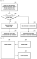
- a method for determining whether the base station schedules the base station as the first type transmission or as the second type transmission will be described with reference to FIG. 11 .
- the base station configures whether signals to be scheduled correspond to the first type transmission or the second type transmission through higher layer signaling (1101), and checks whether the TA value of the corresponding terminal is larger than a specific limit value (1103).
- the base station transmits the control signal to the terminal, for example, it transmits the control signal in a terminal-specific search space (1105). In this case, it is determined that the transmission corresponding to the control signal is the first type transmission (1107).
- the base station transmits the control signal to the terminal, for example, it transmits the control signal in the common search space (1109). In this case, it is determined that the transmission corresponding to the control signal is the second type transmission (1111).
- the fourth embodiment is related to a method for releasing configuration of the first type transmission that the base station configures with respect to the terminal through higher layer signaling if the EA value of the corresponding terminal exceeds a specific TA limit value.
- the base station configures whether signals to be scheduled correspond to the first type transmission or the second type transmission through higher layer signaling. If the timing advance value of the terminal become larger than the first TA limit value or a value that is obtained by adding or multiplying a specific value to or by the first TA limit value in a state where the terminal is configured as the first type transmission, it may be assumed that the base station and the terminal have released the first type transmission configuration.
- releasing of the first type transmission configuration may mean the configuration as the second type transmission. Further, on condition that the timing advance value of the terminal become larger than the first TA limit value or a value obtained by adding or multiplying a specific value to or by the first TA value, it is possible to change and apply the timing advance value of the terminal so that the timing advance value becomes larger than the n-th TA limit value or the value obtained by adding or multiplying the specific value to or by the n-th TA limit value first TA value
- the TA value of the terminal may be changed by applying a new TA value through reception of a random access response (RAR) from the base station, or by receiving a variation value of the TA value transferred from the base station through the MAC CE.
- RAR random access response
- the second to fourth embodiments have been described on the assumption that the base station knows the TA value of the terminal, the embodiments may also be applied even in the case where the base station does not know the TA value of the terminal.
- determination of a transmission failure with respect to data transmitted by the base station or the terminal may correspond to a case of discontinuous transmission (DTX) (e.g., a case where neither the ACK nor the NACK is received) or a case where the NACK is transferred.
- DTX discontinuous transmission
- the base station schedules the first type transmission with respect to the terminal for the downlink or the uplink. If the base station fails to detect the second signal that is a response signal of the terminal connected to the first signal corresponding to the scheduled first type transmission, it determines that the transmission of the scheduled first type to the terminal has failed. In this case, if the transmission of the scheduled first type to the terminal has failed N times, the base station determines that the corresponding terminal is in a state where the first type transmission is currently impossible, and schedules only the second type transmission.
- the reason why the first type transmission is determined to be impossible is that the channel state toward the terminal is not good, or the sufficient processing time is not secured when the terminal applies the TA value due to a long distance from the terminal.
- the N times failure of the first type transmission scheduling may be successive or may be accumulatively calculated. Further, the integer N may be a pre-engaged value, but may be a value pre-transferred to the terminal through the higher layer signaling.
- the base station may continuously determine that the first type transmission is impossible from the time when it is determined that the first type transmission is impossible due to the N times failure to a predetermined time. In this case, the base station may attempt again the first type transmission with respect to the terminal after the predetermined time.
- the base station may transmit the downlink data to the corresponding terminal as the second type transmission.
- the base station detects the second signal that is the response signal of the terminal connected to the first signal corresponding to the first type transmission, it may determine that the first type transmission is possible.
- the base station may derive physical random access channel (PRACH) transmission from the terminal through the PDCCH order.
- PRACH physical random access channel
- the base station schedules the first type transmission with respect to the terminal for the downlink or the uplink. In this case, if the base station has failed to detect the second signal that is the response signal of the terminal connected to the first signal corresponding to the scheduled first type transmission, it determines that the first type transmission scheduled to the terminal has failed. If the first type transmission has failed N times, the base station puts down the PDCCH order that is a command for the corresponding terminal to perform the PRACH.
- the PDCCH order may be a command for commanding the terminal to transmit the PRACH signal through a determined time-frequency resource through a physical layer signal or higher layer signaling.
- the N times failure of the first type transmission scheduling may be successive or may be accumulatively calculated.
- the integer N may be a pre-engaged value, but may be a value pre-transferred to the terminal through the higher layer signaling.
- the base station may continuously determine that the first type transmission is impossible from the time when it is determined that the first type transmission is impossible due to the N times failure to a predetermined time. After the predetermined time, the base station may attempt again the first type transmission or may put down the PDCCH order again.
- the base station Since the base station receives a random access preamble from the terminal corresponding to the PDCCH order, it may calculate the absolute TA value for the terminal based on this. Then, the base station may determine the transmission type for the terminal based on the calculated absolute TA value. In contrast, if the base station receives the second signal that is the response signal of the terminal connected to the first signal corresponding to the first type transmission, it may determine that the first type transmission is possible.
- transmitters, receivers, and processors of a terminal and a base station are illustrated in FIGS. 12 and 13 .
- a transmission/reception method of a base station and a terminal is provided to determine a method for mapping a control signal for the base station and a method for detecting the control signal for the terminal and to perform the corresponding operations, and in order to perform this, the receivers, processors, and transmitters of the base station and the terminal should operate in accordance with the respective embodiments.
- FIG. 12 illustrates the internal configuration of a terminal that performs operations according to the embodiments of the present disclosure.
- a terminal may include a terminal receiver 1200, a terminal transmitter 1204, and a terminal processor 1202.
- the terminal receiver 1200 and the terminal transmitter 1204 may be commonly called a transceiver.
- the transceiver of the terminal may transmit/receive a signal to/from a base station.
- the signal may include control information and data.
- the transceiver may include an RF transmitter up-converting and amplifying a frequency of a transmitted signal, and an RF receiver low-noise-amplifying the received signal and down-converting the frequency of the amplified signal.
- the transceiver of the terminal may receive the signal through a radio channel, output the signal to the terminal processor 1202, and transmit the signal output from the terminal processor 1202 through the radio channel.
- the terminal processor 1202 may control a series of processes so that the terminal can operate according to the embodiments of the present disclosure.
- the terminal receiver 1200 may receive the signal including the first type transmission configuration information from the base station, and the terminal processor 1202 may select a method for detecting the control signal in accordance with the configuration information and TA values.
- FIG. 13 illustrates the internal configuration of a base station that performs operations according to the embodiments of the present disclosure.
- a base station may include a base station receiver 1301, a base station transmitter 1305, and a base station processor 1303.
- the base station receiver 1301 and the base station transmitter 1305 may be commonly called a transceiver.
- the transceiver of the base station may transmit/receive a signal to/from a terminal.
- the signal may include control information and data.
- the transceiver may include an RF transmitter up-converting and amplifying a frequency of a transmitted signal, and an RF receiver low-noise-amplifying the received signal and down-converting the frequency of the amplified signal.
- the transceiver of the base station may receive the signal through a radio channel, output the signal to the base station processor 1303, and transmit the signal output from the base station processor 1303 through the radio channel.
- the base station processor 1303 may control a series of processes so that the base station can operate according to the embodiments of the present disclosure. For example, the base station processor 1303 may select whether to perform the first type transmission with respect to the terminal, determine the TA value of the corresponding terminal, and select a method for mapping the control signal (method for determining a search space to transmit the control signal). Thereafter, the base station transmitter 1305 transmits the control signal in accordance with the determined method for mapping the control signal.
- the respective embodiments may be combined with each other to be operated.
- portions of the embodiments 1 to 4 of the present disclosure may be combined with each other to be operated by the base station and the terminal.
- the above-described embodiments are presented based on the FDD LTE system, they may be applied to other systems, such as a TDD LTE system, and 5G or NR system, and other modifications based on the technical idea of the embodiments can be embodied.
- the uplink scheduling grant signal and the downlink data signal are called the first signal
- the uplink data signal for the uplink scheduling grant and the HARQ ACK/NACK for the downlink data signal are called the second signal.
- the kinds of the first signal and the second signal as described above are merely exemplary to easily explain the technical contents of the present disclosure and to help understanding of the present disclosure, but are not intended to limit the scope of the present disclosure. That is, it will be apparent to those of ordinary skill in the art to which the present disclosure pertains that other first and second signals can be embodied based on the technical idea of the present disclosure.
Claims (12)
- Verfahren für eine Basisstation in einem drahtlosen Kommunikationssystem, umfassend:Übertragen (1101) einer Konfigurationsnachricht zum Einstellen eines Übertragungstyps des Endgeräts auf einen ersten Übertragungstyp an ein Endgerät, wobei der Übertragungstyp den ersten Übertragungstyp und einen zweiten Übertragungstyp enthält, die basierend auf einem Übertragungszeitintervall bestimmt werden;Identifizieren (1103), ob ein Zeitvorlaufwert des Endgeräts kleiner als ein vorbestimmter Wert ist; dadurch gekennzeichnet, dass das Verfahren ferner Folgendes umfasst:Übertragen (1105) von Steuerungsinformationen, die dem ersten Übertragungstyp zugeordnet sind, an das Endgerät in einem ersten Suchraum, basierend darauf, dass der Zeitvorlauf des Endgeräts kleiner als der vorbestimmte Wert ist; undÜbertragen (1107) von Steuerungsinformationen, die dem zweiten Übertragungstyp zugeordnet sind, an das Endgerät in einem zweiten Suchraum, basierend darauf, dass der Zeitvorlaufwert des Endgeräts größer als der vorbestimmte Wert ist, wobei der erste Übertragungstyp eine verkürzte TTI-Übertragung ist, und wobei der zweite Übertragungstyp eine normale TTI-Übertragung ist,wobei der erste Suchraum ein endgerätespezifischer Suchraum ist, undwobei der zweite Suchraum ein gemeinsamer Suchraum ist.
- Verfahren nach Anspruch 1,wobei der erste Übertragungstyp mindestens eine Übertragung enthält, die das Übertragungszeitintervall einer ersten Zeitdauer verwendet,wobei der zweite Übertragungstyp mindestens eine Übertragung enthält, die das Übertragungszeitintervall einer zweiten Zeitdauer verwendet, die länger als die erste Zeitdauer ist, undwobei eine Übertragung eines Uplink-Signals basierend auf dem ersten Übertragungstyp schneller ist als eine Übertragung des Uplink-Signals basierend auf dem zweiten Übertragungstyp, wobei das Uplink-Signal als Reaktion auf ein Downlink-Signal übertragen wird.
- Verfahren nach Anspruch 1,
wobei die Konfigurationsnachricht eine Radio Resource Control(RRC)-Nachricht ist. - Verfahren nach Anspruch 1, wobei der Übertragungstyp des Endgeräts basierend auf dem Zeitvorlaufwert des Endgeräts bestimmt wird.
- Verfahren für ein Endgerät in einem drahtlosen Kommunikationssystem, umfassend:Empfangen (1001) einer Konfigurationsnachricht zum Einstellen eines Übertragungstyps des Endgeräts auf einen ersten Übertragungstyp von einer Basisstation, wobei der Übertragungstyp den ersten Übertragungstyp und einen zweiten Übertragungstyp enthält, die basierend auf einem Übertragungszeitintervall bestimmt werden;Identifizieren (1003), ob ein Zeitvorlaufwert des Endgeräts kleiner als ein vorbestimmter Wert ist; dadurch gekennzeichnet, dass das Verfahren ferner Folgendes umfasst:Überwachen (1005) von Steuerungsinformationen, die dem ersten Übertragungstyp zugeordnet sind, in einem ersten Suchraum, basierend darauf, dass der Zeitvorlaufwert des Endgeräts kleiner als der vorbestimmte Wert ist; undÜberwachen (1009) von Steuerungsinformationen, die dem zweiten Übertragungstyp zugeordnet sind, in einem zweiten Suchraum, basierend darauf, dass der Zeitvorlaufwert des Endgeräts größer als der vorbestimmte Wert ist, wobei der erste Übertragungstyp eine verkürzte TTI-Übertragung ist, und wobei der zweite Übertragungstyp eine normale TTI-Übertragung ist,wobei der erste Suchraum ein endgerätespezifischer Suchraum ist, undwobei der zweite Suchraum ein gemeinsamer Suchraum ist.
- Verfahren nach Anspruch 5,wobei der erste Übertragungstyp mindestens eine Übertragung enthält, die das Übertragungszeitintervall einer ersten Zeitdauer verwendet,wobei der zweite Übertragungstyp mindestens eine Übertragung enthält, die das Übertragungszeitintervall einer zweiten Zeitdauer verwendet, die länger als die erste Zeitdauer ist, undwobei eine Übertragung eines Uplink-Signals basierend auf dem ersten Übertragungstyp schneller ist als eine Übertragung des Uplink-Signals basierend auf dem zweiten Übertragungstyp, wobei das Uplink-Signal als Reaktion auf ein Downlink-Signal übertragen wird.
- Basisstation für ein drahtloses Kommunikationssystem, wobei die Basisstation konfiguriert ist zum:Übertragen einer Konfigurationsnachricht zum Einstellen eines Übertragungstyps des Endgeräts auf einen ersten Übertragungstyp über den Transceiver an ein Endgerät, wobei der Übertragungstyp den ersten Übertragungstyp und einen zweiten Übertragungstyp enthält, die basierend auf einem Übertragungszeitintervall bestimmt werden;Identifizieren, ob ein Zeitvorlaufwert des Endgeräts kleiner als ein vorbestimmter Wert ist; dadurch gekennzeichnet, dass die Basisstation ferner zum Übertragen von Steuerungsinformationen, die dem ersten Übertragungstyp zugeordnet sind, konfiguriert ist, in einem ersten Suchraum über den Transceiver an das Endgerät, basierend darauf, dass der Zeitvorlaufwert des Endgeräts kleiner als der vorbestimmte Wert ist; undÜbertragen von Steuerungsinformationen, die dem zweiten Übertragungstyp in einem zweiten Suchraum zugeordnet sind, über den Transceiver an das Endgerät, basierend darauf, dass der Zeitvorlaufwert des Endgeräts größer als der vorbestimmte Wert ist, wobei der erste Übertragungstyp eine verkürzte TTI-Übertragung ist, und wobei der zweite Übertragungstyp eine normale TTI-Übertragung ist,wobei der erste Suchraum ein endgerätespezifischer Suchraum ist, undwobei der zweite Suchraum ein gemeinsamer Suchraum ist.
- Basisstation nach Anspruch 7,wobei der erste Übertragungstyp mindestens eine Übertragung enthält, die das Übertragungszeitintervall einer ersten Zeitdauer verwendet,wobei der zweite Übertragungstyp mindestens eine Übertragung enthält, die das Übertragungszeitintervall einer zweiten Zeitdauer verwendet, die länger als die erste Zeitdauer ist, undwobei eine Übertragung eines Uplink-Signals basierend auf dem ersten Übertragungstyp schneller ist als eine Übertragung des Uplink-Signals basierend auf dem zweiten Übertragungstyp, wobei das Uplink-Signal als Reaktion auf ein Downlink-Signal übertragen wird.
- Basisstation nach Anspruch 7, wobei die Konfigurationsnachricht eine Radio Resource Control(RRC)-Nachricht ist.
- Basisstation nach Anspruch 7, wobei die Basisstation so konfiguriert ist, dass sie den Übertragungstyp des Endgeräts basierend auf dem Zeitvorlaufwert des Endgeräts bestimmt.
- Endgerät für ein drahtloses Kommunikationssystem, wobei das Endgerät konfiguriert ist zum:Empfangen einer Konfigurationsnachricht über den Transceiver von einer Basisstation zum Einstellen eines Übertragungstyps des Endgeräts auf einen ersten Übertragungstyp, wobei der Übertragungstyp den ersten Übertragungstyp und einen zweiten Übertragungstyp enthält, die basierend auf einem Übertragungszeitintervall bestimmt werden;Identifizieren eines Zeitvorlaufwerts des Endgeräts;Überwachen von Steuerungsinformationen, die dem ersten Übertragungstyp zugeordnet sind, in einem ersten Suchraum, basierend darauf, dass der Zeitvorlaufwert des Endgeräts kleiner als ein vorbestimmter Wert ist; undÜberwachen von Steuerungsinformationen, die dem zweiten Übertragungstyp zugeordnet sind, in einem zweiten Suchraum, basierend darauf, dass der Zeitvorlaufwert des Endgeräts größer als der vorbestimmte Wert ist, wobei der erste Übertragungstyp eine verkürzte TTI-Übertragung ist, und wobei der zweite Übertragungstyp eine normale TTI-Übertragung ist,wobei der erste Suchraum ein endgerätespezifischer Suchraum ist, undwobei der zweite Suchraum ein gemeinsamer Suchraum ist.
- Endgerät nach Anspruch 11,wobei der erste Übertragungstyp mindestens eine Übertragung enthält, die das Übertragungszeitintervall einer ersten Zeitdauer verwendet,wobei der zweite Übertragungstyp mindestens eine Übertragung enthält, die das Übertragungszeitintervall einer zweiten Zeitdauer verwendet, die länger als die erste Zeitdauer ist, undwobei eine Übertragung eines Uplink-Signals basierend auf dem ersten Übertragungstyp schneller ist als eine Übertragung des Uplink-Signals basierend auf dem zweiten Übertragungstyp, wobei das Uplink-Signal als Reaktion auf ein Downlink-Signal übertragen wird.
Applications Claiming Priority (2)
| Application Number | Priority Date | Filing Date | Title |
|---|---|---|---|
| KR1020160130888A KR102638922B1 (ko) | 2016-10-10 | 2016-10-10 | 무선 셀룰라 통신 시스템에서 다중 타이밍 전송 기술의 송수신 방법 및 장치 |
| PCT/KR2017/011130 WO2018070757A1 (en) | 2016-10-10 | 2017-10-10 | Method and apparatus for transmitting and receiving multiple timing transmission schemes in wireless cellular communication system |
Publications (3)
| Publication Number | Publication Date |
|---|---|
| EP3510717A1 EP3510717A1 (de) | 2019-07-17 |
| EP3510717A4 EP3510717A4 (de) | 2019-09-18 |
| EP3510717B1 true EP3510717B1 (de) | 2023-06-21 |
Family
ID=61829337
Family Applications (1)
| Application Number | Title | Priority Date | Filing Date |
|---|---|---|---|
| EP17861079.6A Active EP3510717B1 (de) | 2016-10-10 | 2017-10-10 | Verfahren und vorrichtung zum senden und empfangen von übertragungsschemen mit mehrfachen timing in drahtlosem zellularem kommunikationssystem |
Country Status (5)
| Country | Link |
|---|---|
| US (1) | US10484975B2 (de) |
| EP (1) | EP3510717B1 (de) |
| KR (1) | KR102638922B1 (de) |
| CN (1) | CN109845169B (de) |
| WO (1) | WO2018070757A1 (de) |
Families Citing this family (9)
| Publication number | Priority date | Publication date | Assignee | Title |
|---|---|---|---|---|
| KR20180049748A (ko) | 2016-11-03 | 2018-05-11 | 삼성전자주식회사 | 무선 셀룰라 통신 시스템에서 제어신호 검출 방법 및 장치 |
| KR102616557B1 (ko) | 2018-02-13 | 2023-12-26 | 삼성전자 주식회사 | 무선 통신 시스템에서 데이터 및 제어 정보 송수신 방법 및 장치 |
| US11477809B2 (en) * | 2018-04-12 | 2022-10-18 | Qualcomm Incorporated | Techniques for channel estimation |
| CN110536340B (zh) * | 2018-05-25 | 2022-03-29 | 华为技术有限公司 | 信息传输方法、装置及存储介质 |
| US11349609B2 (en) * | 2018-11-05 | 2022-05-31 | Qualcomm Incorporated | Hybrid automatic repeat request acknowledgement feedback enhancement for new radio-unlicensed |
| CA3126043A1 (en) * | 2019-02-14 | 2020-08-20 | Ntt Docomo, Inc. | User equipment and communication method |
| CN112153556A (zh) * | 2019-06-28 | 2020-12-29 | 中国移动通信有限公司研究院 | 一种信号传输方法、通信设备及基站 |
| CN111585711B (zh) * | 2020-04-28 | 2021-03-26 | 广州技象科技有限公司 | 一种窄带物联网的上行数据发送方法及装置 |
| KR20220018824A (ko) * | 2020-08-07 | 2022-02-15 | 삼성전자주식회사 | 통신 시스템에서 스케줄링 타이밍 결정 방법 및 장치 |
Family Cites Families (29)
| Publication number | Priority date | Publication date | Assignee | Title |
|---|---|---|---|---|
| JP4698498B2 (ja) | 2006-06-19 | 2011-06-08 | 株式会社エヌ・ティ・ティ・ドコモ | 基地局、移動局および通信方法 |
| ATE554555T1 (de) | 2007-07-26 | 2012-05-15 | Ericsson Telefon Ab L M | Vorrichtung und verfahren zur steuerung von uplink-übertragungen in ofdma-systemen |
| JP5069147B2 (ja) | 2008-02-29 | 2012-11-07 | 株式会社エヌ・ティ・ティ・ドコモ | 移動通信システム、基地局装置、ユーザ装置及び方法 |
| CN102196479B (zh) * | 2010-03-10 | 2014-01-08 | 华为技术有限公司 | 定时提前值的共享检测方法、用户设备、基站及系统 |
| CN102684855A (zh) * | 2011-03-11 | 2012-09-19 | 北京三星通信技术研究有限公司 | 一种混合自动重传定时关系的指示方法 |
| CN103609084B (zh) * | 2011-06-15 | 2017-04-12 | 三星电子株式会社 | 通信系统中物理下行链路控制信令的延伸 |
| CN102325378B (zh) * | 2011-08-31 | 2015-02-18 | 新邮通信设备有限公司 | 控制物理下行控制信道传输的方法和设备 |
| KR20130045169A (ko) * | 2011-10-24 | 2013-05-03 | 주식회사 팬택 | 다중 요소 반송파 시스템에서 상향링크 동기의 수행장치 및 방법 |
| US9635658B2 (en) * | 2012-02-27 | 2017-04-25 | Samsung Electronics Co., Ltd. | Adaptation of control signaling transmissions to variations in respective resources |
| US9113462B2 (en) * | 2012-05-03 | 2015-08-18 | Qualcomm Incorporated | Resource mapping for ePDCCH in LTE |
| US8761109B2 (en) * | 2012-08-03 | 2014-06-24 | Motorola Mobility Llc | Method and apparatus for receiving a control channel |
| US9131498B2 (en) | 2012-09-12 | 2015-09-08 | Futurewei Technologies, Inc. | System and method for adaptive transmission time interval (TTI) structure |
| US20150305065A1 (en) * | 2012-10-19 | 2015-10-22 | Broadcom Corporation | Random access procedure and related apparatus |
| WO2014142593A1 (ko) * | 2013-03-13 | 2014-09-18 | 엘지전자 주식회사 | 제어 채널의 송수신 방법 및 이를 위한 장치 |
| US9210562B2 (en) * | 2013-04-04 | 2015-12-08 | Blackberry Limited | Method and apparatus for proximity discovery for device-to-device communication |
| US10856277B2 (en) * | 2013-05-12 | 2020-12-01 | Lg Electronics Inc. | Method for receiving information by MTC device located in cell coverage-expanded area |
| JP6125939B2 (ja) * | 2013-07-29 | 2017-05-10 | 京セラ株式会社 | ユーザ端末及びプロセッサ |
| US9763199B2 (en) * | 2014-01-29 | 2017-09-12 | Interdigital Patent Holdings, Inc. | Uplink transmissions in wireless communications |
| CN104955155B (zh) * | 2014-03-31 | 2019-01-01 | 中国电信股份有限公司 | PDSCH数据接收方法、发送方法、用户设备和eNB |
| US10136428B2 (en) * | 2014-05-21 | 2018-11-20 | Lg Electronics Inc. | Resource allocation method for communication between transmitting and receiving terminals in communication system supporting direct device-to-device communication and apparatus for same |
| US20150373703A1 (en) * | 2014-06-18 | 2015-12-24 | Mediatek Inc. | Method of Aligning Frame Transmission to Deterministic Time and Related Wireless Device |
| WO2016040290A1 (en) | 2014-09-08 | 2016-03-17 | Interdigital Patent Holdings, Inc. | Systems and methods of operating with different transmission time interval (tti) durations |
| CN113765630B (zh) * | 2015-04-02 | 2024-02-27 | 三星电子株式会社 | 无线通信系统中的终端和基站及其执行的方法 |
| WO2017005295A1 (en) * | 2015-07-06 | 2017-01-12 | Telefonaktiebolaget Lm Ericsson (Publ) | Resource allocation for data transmission in wireless systems |
| WO2017035300A1 (en) * | 2015-08-25 | 2017-03-02 | Idac Holdings, Inc. | Framing, scheduling, and synchronization in wireless systems |
| US11496872B2 (en) * | 2015-11-06 | 2022-11-08 | Qualcomm Incorporated | Search spaces and grants in eMTC |
| US10201006B2 (en) * | 2016-04-01 | 2019-02-05 | Qualcomm Incorporated | Downlink control information for multi-layer transmissions |
| CN107371257B (zh) * | 2016-05-12 | 2020-04-28 | 华硕电脑股份有限公司 | 改善短传输时间间隔的控制信道结构的方法及装置 |
| US10205581B2 (en) * | 2016-09-22 | 2019-02-12 | Huawei Technologies Co., Ltd. | Flexible slot architecture for low latency communication |
-
2016
- 2016-10-10 KR KR1020160130888A patent/KR102638922B1/ko active IP Right Grant
-
2017
- 2017-10-10 EP EP17861079.6A patent/EP3510717B1/de active Active
- 2017-10-10 CN CN201780062654.9A patent/CN109845169B/zh active Active
- 2017-10-10 US US15/729,233 patent/US10484975B2/en active Active
- 2017-10-10 WO PCT/KR2017/011130 patent/WO2018070757A1/en unknown
Also Published As
| Publication number | Publication date |
|---|---|
| US20180103462A1 (en) | 2018-04-12 |
| EP3510717A1 (de) | 2019-07-17 |
| WO2018070757A1 (en) | 2018-04-19 |
| CN109845169A (zh) | 2019-06-04 |
| KR102638922B1 (ko) | 2024-02-22 |
| CN109845169B (zh) | 2022-02-18 |
| US10484975B2 (en) | 2019-11-19 |
| EP3510717A4 (de) | 2019-09-18 |
| KR20180039504A (ko) | 2018-04-18 |
Similar Documents
| Publication | Publication Date | Title |
|---|---|---|
| US11924849B2 (en) | Method and apparatus for transmitting control and data information in wireless cellular communication system | |
| EP3510717B1 (de) | Verfahren und vorrichtung zum senden und empfangen von übertragungsschemen mit mehrfachen timing in drahtlosem zellularem kommunikationssystem | |
| CN110999496B (zh) | 在无线通信系统中设置下行链路控制信道接收时间的方法和装置 | |
| US11652578B2 (en) | Method and apparatus for determining transmission timing in wireless communication system | |
| US11425755B2 (en) | Method and apparatus for identifying uplink signal transmission timing in wireless communication system | |
| CN109196809B (zh) | 在无线通信系统中确定上行数据和控制信号发送定时的方法和设备 | |
| US11611940B2 (en) | Method and apparatus for uplink power control in wireless cellular communication system | |
| US10524248B2 (en) | Method and apparatus for detecting downlink control signal in wireless communication system | |
| US10986619B2 (en) | Method and apparatus for determining uplink transmission timing in wireless communication system | |
| CN110050430B (zh) | 用于在无线蜂窝通信系统中解码下行链路控制信号的方法和装置 | |
| CN109565850B (zh) | 用于在无线蜂窝通信中减少等待时间的发射方法和设备 |
Legal Events
| Date | Code | Title | Description |
|---|---|---|---|
| STAA | Information on the status of an ep patent application or granted ep patent |
Free format text: STATUS: THE INTERNATIONAL PUBLICATION HAS BEEN MADE |
|
| PUAI | Public reference made under article 153(3) epc to a published international application that has entered the european phase |
Free format text: ORIGINAL CODE: 0009012 |
|
| STAA | Information on the status of an ep patent application or granted ep patent |
Free format text: STATUS: REQUEST FOR EXAMINATION WAS MADE |
|
| 17P | Request for examination filed |
Effective date: 20190410 |
|
| AK | Designated contracting states |
Kind code of ref document: A1 Designated state(s): AL AT BE BG CH CY CZ DE DK EE ES FI FR GB GR HR HU IE IS IT LI LT LU LV MC MK MT NL NO PL PT RO RS SE SI SK SM TR |
|
| AX | Request for extension of the european patent |
Extension state: BA ME |
|
| REG | Reference to a national code |
Ref document number: 602017070519 Country of ref document: DE Ref country code: DE Ref legal event code: R079 Free format text: PREVIOUS MAIN CLASS: H04L0005000000 Ipc: H04L0001180000 |
|
| A4 | Supplementary search report drawn up and despatched |
Effective date: 20190821 |
|
| RIC1 | Information provided on ipc code assigned before grant |
Ipc: H04L 1/18 20060101AFI20190815BHEP Ipc: H04L 5/00 20060101ALI20190815BHEP Ipc: H04W 72/04 20090101ALI20190815BHEP |
|
| DAV | Request for validation of the european patent (deleted) | ||
| DAX | Request for extension of the european patent (deleted) | ||
| STAA | Information on the status of an ep patent application or granted ep patent |
Free format text: STATUS: EXAMINATION IS IN PROGRESS |
|
| 17Q | First examination report despatched |
Effective date: 20210312 |
|
| STAA | Information on the status of an ep patent application or granted ep patent |
Free format text: STATUS: EXAMINATION IS IN PROGRESS |
|
| GRAP | Despatch of communication of intention to grant a patent |
Free format text: ORIGINAL CODE: EPIDOSNIGR1 |
|
| STAA | Information on the status of an ep patent application or granted ep patent |
Free format text: STATUS: GRANT OF PATENT IS INTENDED |
|
| INTG | Intention to grant announced |
Effective date: 20230323 |
|
| GRAS | Grant fee paid |
Free format text: ORIGINAL CODE: EPIDOSNIGR3 |
|
| GRAA | (expected) grant |
Free format text: ORIGINAL CODE: 0009210 |
|
| STAA | Information on the status of an ep patent application or granted ep patent |
Free format text: STATUS: THE PATENT HAS BEEN GRANTED |
|
| AK | Designated contracting states |
Kind code of ref document: B1 Designated state(s): AL AT BE BG CH CY CZ DE DK EE ES FI FR GB GR HR HU IE IS IT LI LT LU LV MC MK MT NL NO PL PT RO RS SE SI SK SM TR |
|
| REG | Reference to a national code |
Ref country code: CH Ref legal event code: EP |
|
| REG | Reference to a national code |
Ref country code: DE Ref legal event code: R096 Ref document number: 602017070519 Country of ref document: DE |
|
| REG | Reference to a national code |
Ref country code: AT Ref legal event code: REF Ref document number: 1581668 Country of ref document: AT Kind code of ref document: T Effective date: 20230715 |
|
| REG | Reference to a national code |
Ref country code: IE Ref legal event code: FG4D |
|
| REG | Reference to a national code |
Ref country code: LT Ref legal event code: MG9D |
|
| REG | Reference to a national code |
Ref country code: NL Ref legal event code: MP Effective date: 20230621 |
|
| PG25 | Lapsed in a contracting state [announced via postgrant information from national office to epo] |
Ref country code: SE Free format text: LAPSE BECAUSE OF FAILURE TO SUBMIT A TRANSLATION OF THE DESCRIPTION OR TO PAY THE FEE WITHIN THE PRESCRIBED TIME-LIMIT Effective date: 20230621 Ref country code: NO Free format text: LAPSE BECAUSE OF FAILURE TO SUBMIT A TRANSLATION OF THE DESCRIPTION OR TO PAY THE FEE WITHIN THE PRESCRIBED TIME-LIMIT Effective date: 20230921 |
|
| PGFP | Annual fee paid to national office [announced via postgrant information from national office to epo] |
Ref country code: GB Payment date: 20230920 Year of fee payment: 7 |
|
| REG | Reference to a national code |
Ref country code: AT Ref legal event code: MK05 Ref document number: 1581668 Country of ref document: AT Kind code of ref document: T Effective date: 20230621 |
|
| PG25 | Lapsed in a contracting state [announced via postgrant information from national office to epo] |
Ref country code: RS Free format text: LAPSE BECAUSE OF FAILURE TO SUBMIT A TRANSLATION OF THE DESCRIPTION OR TO PAY THE FEE WITHIN THE PRESCRIBED TIME-LIMIT Effective date: 20230621 Ref country code: NL Free format text: LAPSE BECAUSE OF FAILURE TO SUBMIT A TRANSLATION OF THE DESCRIPTION OR TO PAY THE FEE WITHIN THE PRESCRIBED TIME-LIMIT Effective date: 20230621 Ref country code: LV Free format text: LAPSE BECAUSE OF FAILURE TO SUBMIT A TRANSLATION OF THE DESCRIPTION OR TO PAY THE FEE WITHIN THE PRESCRIBED TIME-LIMIT Effective date: 20230621 Ref country code: LT Free format text: LAPSE BECAUSE OF FAILURE TO SUBMIT A TRANSLATION OF THE DESCRIPTION OR TO PAY THE FEE WITHIN THE PRESCRIBED TIME-LIMIT Effective date: 20230621 Ref country code: HR Free format text: LAPSE BECAUSE OF FAILURE TO SUBMIT A TRANSLATION OF THE DESCRIPTION OR TO PAY THE FEE WITHIN THE PRESCRIBED TIME-LIMIT Effective date: 20230621 Ref country code: GR Free format text: LAPSE BECAUSE OF FAILURE TO SUBMIT A TRANSLATION OF THE DESCRIPTION OR TO PAY THE FEE WITHIN THE PRESCRIBED TIME-LIMIT Effective date: 20230922 |
|
| PG25 | Lapsed in a contracting state [announced via postgrant information from national office to epo] |
Ref country code: FI Free format text: LAPSE BECAUSE OF FAILURE TO SUBMIT A TRANSLATION OF THE DESCRIPTION OR TO PAY THE FEE WITHIN THE PRESCRIBED TIME-LIMIT Effective date: 20230621 |
|
| PG25 | Lapsed in a contracting state [announced via postgrant information from national office to epo] |
Ref country code: SK Free format text: LAPSE BECAUSE OF FAILURE TO SUBMIT A TRANSLATION OF THE DESCRIPTION OR TO PAY THE FEE WITHIN THE PRESCRIBED TIME-LIMIT Effective date: 20230621 |
|
| PG25 | Lapsed in a contracting state [announced via postgrant information from national office to epo] |
Ref country code: ES Free format text: LAPSE BECAUSE OF FAILURE TO SUBMIT A TRANSLATION OF THE DESCRIPTION OR TO PAY THE FEE WITHIN THE PRESCRIBED TIME-LIMIT Effective date: 20230621 |
|
| PG25 | Lapsed in a contracting state [announced via postgrant information from national office to epo] |
Ref country code: IS Free format text: LAPSE BECAUSE OF FAILURE TO SUBMIT A TRANSLATION OF THE DESCRIPTION OR TO PAY THE FEE WITHIN THE PRESCRIBED TIME-LIMIT Effective date: 20231021 |
|
| PG25 | Lapsed in a contracting state [announced via postgrant information from national office to epo] |
Ref country code: SM Free format text: LAPSE BECAUSE OF FAILURE TO SUBMIT A TRANSLATION OF THE DESCRIPTION OR TO PAY THE FEE WITHIN THE PRESCRIBED TIME-LIMIT Effective date: 20230621 Ref country code: SK Free format text: LAPSE BECAUSE OF FAILURE TO SUBMIT A TRANSLATION OF THE DESCRIPTION OR TO PAY THE FEE WITHIN THE PRESCRIBED TIME-LIMIT Effective date: 20230621 Ref country code: RO Free format text: LAPSE BECAUSE OF FAILURE TO SUBMIT A TRANSLATION OF THE DESCRIPTION OR TO PAY THE FEE WITHIN THE PRESCRIBED TIME-LIMIT Effective date: 20230621 Ref country code: PT Free format text: LAPSE BECAUSE OF FAILURE TO SUBMIT A TRANSLATION OF THE DESCRIPTION OR TO PAY THE FEE WITHIN THE PRESCRIBED TIME-LIMIT Effective date: 20231023 Ref country code: IS Free format text: LAPSE BECAUSE OF FAILURE TO SUBMIT A TRANSLATION OF THE DESCRIPTION OR TO PAY THE FEE WITHIN THE PRESCRIBED TIME-LIMIT Effective date: 20231021 Ref country code: ES Free format text: LAPSE BECAUSE OF FAILURE TO SUBMIT A TRANSLATION OF THE DESCRIPTION OR TO PAY THE FEE WITHIN THE PRESCRIBED TIME-LIMIT Effective date: 20230621 Ref country code: EE Free format text: LAPSE BECAUSE OF FAILURE TO SUBMIT A TRANSLATION OF THE DESCRIPTION OR TO PAY THE FEE WITHIN THE PRESCRIBED TIME-LIMIT Effective date: 20230621 Ref country code: CZ Free format text: LAPSE BECAUSE OF FAILURE TO SUBMIT A TRANSLATION OF THE DESCRIPTION OR TO PAY THE FEE WITHIN THE PRESCRIBED TIME-LIMIT Effective date: 20230621 Ref country code: AT Free format text: LAPSE BECAUSE OF FAILURE TO SUBMIT A TRANSLATION OF THE DESCRIPTION OR TO PAY THE FEE WITHIN THE PRESCRIBED TIME-LIMIT Effective date: 20230621 |
|
| PGFP | Annual fee paid to national office [announced via postgrant information from national office to epo] |
Ref country code: DE Payment date: 20230920 Year of fee payment: 7 |
|
| PG25 | Lapsed in a contracting state [announced via postgrant information from national office to epo] |
Ref country code: PL Free format text: LAPSE BECAUSE OF FAILURE TO SUBMIT A TRANSLATION OF THE DESCRIPTION OR TO PAY THE FEE WITHIN THE PRESCRIBED TIME-LIMIT Effective date: 20230621 |
|
| PLBE | No opposition filed within time limit |
Free format text: ORIGINAL CODE: 0009261 |
|
| STAA | Information on the status of an ep patent application or granted ep patent |
Free format text: STATUS: NO OPPOSITION FILED WITHIN TIME LIMIT |
|
| PG25 | Lapsed in a contracting state [announced via postgrant information from national office to epo] |
Ref country code: DK Free format text: LAPSE BECAUSE OF FAILURE TO SUBMIT A TRANSLATION OF THE DESCRIPTION OR TO PAY THE FEE WITHIN THE PRESCRIBED TIME-LIMIT Effective date: 20230621 |
|
| PG25 | Lapsed in a contracting state [announced via postgrant information from national office to epo] |
Ref country code: SI Free format text: LAPSE BECAUSE OF FAILURE TO SUBMIT A TRANSLATION OF THE DESCRIPTION OR TO PAY THE FEE WITHIN THE PRESCRIBED TIME-LIMIT Effective date: 20230621 |