EP3510324B1 - Ribbon pack for gas burners - Google Patents
Ribbon pack for gas burners Download PDFInfo
- Publication number
- EP3510324B1 EP3510324B1 EP17849378.9A EP17849378A EP3510324B1 EP 3510324 B1 EP3510324 B1 EP 3510324B1 EP 17849378 A EP17849378 A EP 17849378A EP 3510324 B1 EP3510324 B1 EP 3510324B1
- Authority
- EP
- European Patent Office
- Prior art keywords
- ribbon pack
- ribbon
- burner body
- pack
- burner
- Prior art date
- Legal status (The legal status is an assumption and is not a legal conclusion. Google has not performed a legal analysis and makes no representation as to the accuracy of the status listed.)
- Active
Links
Images


Classifications
-
- F—MECHANICAL ENGINEERING; LIGHTING; HEATING; WEAPONS; BLASTING
- F23—COMBUSTION APPARATUS; COMBUSTION PROCESSES
- F23D—BURNERS
- F23D14/00—Burners for combustion of a gas, e.g. of a gas stored under pressure as a liquid
- F23D14/46—Details
- F23D14/48—Nozzles
- F23D14/58—Nozzles characterised by the shape or arrangement of the outlet or outlets from the nozzle, e.g. of annular configuration
- F23D14/583—Nozzles characterised by the shape or arrangement of the outlet or outlets from the nozzle, e.g. of annular configuration of elongated shape, e.g. slits
- F23D14/586—Nozzles characterised by the shape or arrangement of the outlet or outlets from the nozzle, e.g. of annular configuration of elongated shape, e.g. slits formed by a set of sheets, strips, ribbons or the like
-
- F—MECHANICAL ENGINEERING; LIGHTING; HEATING; WEAPONS; BLASTING
- F23—COMBUSTION APPARATUS; COMBUSTION PROCESSES
- F23D—BURNERS
- F23D14/00—Burners for combustion of a gas, e.g. of a gas stored under pressure as a liquid
- F23D14/02—Premix gas burners, i.e. in which gaseous fuel is mixed with combustion air upstream of the combustion zone
- F23D14/04—Premix gas burners, i.e. in which gaseous fuel is mixed with combustion air upstream of the combustion zone induction type, e.g. Bunsen burner
-
- F—MECHANICAL ENGINEERING; LIGHTING; HEATING; WEAPONS; BLASTING
- F23—COMBUSTION APPARATUS; COMBUSTION PROCESSES
- F23D—BURNERS
- F23D14/00—Burners for combustion of a gas, e.g. of a gas stored under pressure as a liquid
- F23D14/02—Premix gas burners, i.e. in which gaseous fuel is mixed with combustion air upstream of the combustion zone
- F23D14/04—Premix gas burners, i.e. in which gaseous fuel is mixed with combustion air upstream of the combustion zone induction type, e.g. Bunsen burner
- F23D14/10—Premix gas burners, i.e. in which gaseous fuel is mixed with combustion air upstream of the combustion zone induction type, e.g. Bunsen burner with elongated tubular burner head
-
- F—MECHANICAL ENGINEERING; LIGHTING; HEATING; WEAPONS; BLASTING
- F23—COMBUSTION APPARATUS; COMBUSTION PROCESSES
- F23D—BURNERS
- F23D14/00—Burners for combustion of a gas, e.g. of a gas stored under pressure as a liquid
- F23D14/46—Details
- F23D14/72—Safety devices, e.g. operative in case of failure of gas supply
- F23D14/78—Cooling burner parts
-
- F—MECHANICAL ENGINEERING; LIGHTING; HEATING; WEAPONS; BLASTING
- F23—COMBUSTION APPARATUS; COMBUSTION PROCESSES
- F23D—BURNERS
- F23D14/00—Burners for combustion of a gas, e.g. of a gas stored under pressure as a liquid
- F23D14/46—Details
- F23D14/84—Flame spreading or otherwise shaping
-
- F—MECHANICAL ENGINEERING; LIGHTING; HEATING; WEAPONS; BLASTING
- F23—COMBUSTION APPARATUS; COMBUSTION PROCESSES
- F23D—BURNERS
- F23D2213/00—Burner manufacture specifications
Definitions
- the present disclosure is directed generally to components for gas burners, and more specifically, to replaceable ribbon packs for gas burners.
- Gas burners are utilized to generate a flame to heat a product using a gaseous fuel such as acetylene, natural gas, and/or propane, among other fuel sources.
- a gaseous fuel such as acetylene, natural gas, and/or propane, among other fuel sources.
- the product being heated can be any product.
- burners are built to individual requirements of either the application or the oven in which they are being utilized. Typically, the burner is designed to provide an even heat release along the burner's length.
- Ribbon burners achieve more effective combustion by significantly increasing the surface area within the burner. For example, tube burners without ribbons may not provide sufficient time for a fuel or mixture to completely burn, so increasing the surface area with ribbons increases fuel consumption and burner efficiency. Ribbon burners are often utilized in heating units where a narrow, uniform sheet or ribbon of flame is desired.
- Ribbons are typically manufactured of stainless steel or a similar metal, and are typically placed in groups of multiple ribbons within a gas burner. For example, a plurality of ribbons can be aligned next to each other and then bolted or otherwise connected to each other and then placed in the gas burner during manufacture. This construction results in the increased surface area and increased efficiency observed with ribbon burners. However, the structure of the ribbons is often negatively altered when they are bolted together or bolted into the gas burner, potentially reducing the surface area and efficacy of the ribbons.
- the burner may have to be returned to the manufacturer, disassembled, and the ribbon pack replaced before being shipped back to the customer.
- the burner might have to be completely replaced when the ribbon pack needs to be replaced, regardless of the state of the gas burner itself
- US 1 500 513 A discloses a gaseous burner comprising a tubular body having a longitudinally directed opening in one side and the edges of the opening turned inwardly to form supporting ribs.
- US 2 607 405 A discloses gas burners of the type embodying corrugated metal ribbons for defining a longitudinal series of contiguous gas discharge ports of relatively small size. Said ribbons are readily removable from the burner head for cleaning and replacement purposes.
- US 2 607 405 A also discloses a grid that comprises a bundle of transversely corrugated metal ribbons whose corrugations define longitudinally extending rows of relatively small-size gas ports and it also comprises a frame or holder of U-shape form for holding said bundle or ribbons in operative position. The degree to which the holder may be pushed down into a slot is limited by overhanging flanges.
- the present invention is directed to a ribbon pack for gas burners and a method for installing a ribbon pack in a gas burner as defined in the accompanying claims.
- Various embodiments and implementations herein are directed to a ribbon pack configuration and structure that provides easy installation into and removal from an existing gas burner, thereby increasing efficiency and enabling use of one of a variety of different ribbon packs.
- a gas burner system includes a longitudinal burner body defining a longitudinal central cavity; and a ribbon pack configured to be removably installed into the central cavity, the ribbon pack comprising: (i) at least one ribbon positioned between a first vertical wall and a second vertical wall; (ii) a first transverse arm extending horizontally outward from a first longitudinal side of the ribbon pack; (iii) a second transverse arm extending horizontally outward from a second longitudinal side of the ribbon pack, wherein the first and second transverse arms are configured to attach to the longitudinal burner body.
- the longitudinal burner body comprises a plurality of ribbon pack connection holes positioned along at least one side of the longitudinal central cavity, and at least one of the first and second transverse arms comprises a plurality of burner body connection holes, the plurality of ribbon pack connection holes and the plurality of burner body connection holes configured to align and receive a connection means to reversibly affix the ribbon pack to the burner body.
- the ribbon pack further comprises an adjusting bolt, and the first vertical wall defines a hole configured to receive the adjusting bolt.
- the ribbon pack further comprises a thread positioned in or on the second vertical wall, the thread configured to receive an end of the adjusting bolt.
- the ribbon pack further comprises a deckle.
- the burner body further defines a cooling channel.
- the burner body is extruded aluminum.
- the ribbon pack includes at least one ribbon positioned between a first vertical wall and a second vertical wall; a first transverse arm extending horizontally outward from a first longitudinal side of the ribbon pack; and a second transverse arm extending horizontally outward from a second longitudinal side of the ribbon pack, wherein the first and second transverse arms are configured to attach to a longitudinal burner body of the gas burner system.
- the ribbon pack is configured to be removably installed into a central cavity of the longitudinal burner body of the gas burner system.
- the method further includes the step of removing the ribbon pack from the burner body. According to an embodiment, the method further includes the step of installing a new ribbon pack in the burner body.
- the present disclosure is directed to methods and systems for ribbon packs for gas burners. It would be beneficial to provide, for example, an easily removable and replaceable ribbon pack.
- a particular goal of utilization of certain embodiments of the present disclosure is to provide a gas burner device or system that carefully packages a plurality of ribbons into a ribbon pack that is then installed into and connected to the gas burner. When the ribbon pack needs to be replaced, it can easily be disconnected from and removed from the gas burner.
- the gas burner 20 includes a mounting component or system configured to allow mounting of the burner body on or in a heating system.
- the burner body 1 includes a mounting rail 10 with one or more mounting bolts 11, which can be utilized to mount the mounting rail 10 to the burner body.
- the ignitor or flame supervision device can be mounted to this rail via brackets.
- the bracket can be designed to slide on the rail, and the brackets can be installed or uninstalled by pushing clips.
- the mounting system can take many different forms and configurations.
- the burner body 1 of the gas burner system is an extruded body.
- the extruded body can be extruded aluminum, among many other possible metals or materials.
- the gas burner 20 can also include one or more components configured to enable operation of the burner. These components may be part of the heating system into which the burner is installed, or may be part of the gas burner itself such that the burner and accompanying components are installed together.
- the gas burner 20 includes at one or both ends of the burner body a reducing nipple 12, a pipe coupling 13, nipple 14, and gas supply connection 15.
- components 12, 13, 14, and/or 15 can form a connection to which the burner body is connected to a gas supply and components 16 and 17 can form a connection by which the burner body is connected to the cooling pipe.
- the burner body can comprise bolts for connection, or slots or holes that enable connection by bolts. Many other connection mechanisms are possible.
- the end of the burner body 1 comprises a plurality of holes or slots that enable a connection to the components and/or to the heating system.
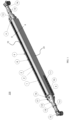
- FIG. 2 is a partially exploded view of the gas burner system 100 of FIG. 1 .
- the gas burner system 100 comprises a burner body 20 and a ribbon pack 22 which is shown as it is being installed or uninstalled.
- the burner body 20 comprises a slot 24 into which the ribbon pack 22 will be positioned when it is installed.
- the slot 24 can be configured to receive a specific ribbon pack, or can be configured to receive a variety of different ribbon packs.
- the ribbon pack 22 comprises two transverse arms 2 which are formed at a right angle to the long axis of the ribbon pack 22.
- the two transverse arms 2 are located at the top of the ribbon pack, and enable the connection with the burner body 1 as described elsewhere herein in greater detail.
- the two transverse arms 2 each comprise a plurality of holes into which a fastening bolt 9 is positioned, which aligns with a thread hole 18.
- the fastening bolt is screwed or fastened into the thread hole 18 to hold the ribbon pack in place.
- each of the fastening bolts 9 are unscrewed or otherwise unfastened from the thread holes 18.
- the ribbon pack 22 also comprises one or more ribbons, with the count being dependent upon a variety of factors including but not limited to the heat input requirement of the heating system, among others.
- FIG. 2 also demonstrates that the burner body 1 can include one or more cooling passages to connect to a cooling water or air supply.
- the coolant fluid or gas enters the burner body 1 at one or more cooling openings 32, flows throughout the burner body, and can exit the burner body via the one or more cooling openings 32, or via different openings or exits.
- the cooling passages can be connected in any way or order to provide efficient cooling when the burner is firing and the cooled burner body keeps the controlled temperature which prevents the deformation of burner body.
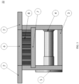
- ribbon pack 22 is a cross-section of ribbon pack 22 taken along axis A-A of FIG. 1 .
- ribbon pack 22 comprises a body formed by two vertical sides separated by top metal spacer 6 and bottom metal spacer 3.
- the metal spacers 3 and 6 determine the distance between the two vertical sides, and define the internal space for the one or more ribbons 8.
- the top metal spacer 6 is connected or adjoining the two transverse arms 2 which extend outwardly from the top of the ribbon pack.
- the ribbon pack also comprises a metal deckle 7, an adjusting bolt 4, and an adjustable thread binding 5.
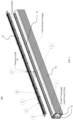
- FIG. 4 is a perspective view of the ribbon pack 22 of the gas burner system 100.
- the ribbon pack 22 comprises a top metal spacer 6, which may be formed, for example, over a portion of the ribbon pack 22.
- the ribbon pack 22 also comprises two transverse arms 2 which extend outwardly from the top of the ribbon pack, with a plurality of holes 26 through which the fastening bolts 9 are inserted to mate with the thread holes 18.
- Also shown in FIG. 4 is the end of the adjusting bolt 4 in the side wall of the ribbon pack 22.
- the insert in FIG. 4 is a top view of the ribbon pack, with two transverse arms 2 which extend outwardly from the top of the ribbon pack, the two arms comprise holes 26 through which the fastening bolts 9 are inserted to mate with the thread holes 18.
- the top view of the ribbon pack also shows the ribbons 8. In this particular embodiment there are eighteen ribbons, but there can be either more or fewer than eighteen ribbons.
- the ribbon pack comprises two side walls with a vertical portion 28 and a transverse arm 2 which extends outwardly away from the ribbons 8.
- the two transverse arms 2 each comprise a plurality of holes into which a fastening bolt 9 is positioned, which aligns with a thread hole 18.
- the fastening bolt is screwed or fastened into the thread hole 18 to hold the ribbon pack in place.
- the ribbon pack also comprises one or more top spacers 6 and a plurality of bottom spacers 3. Also shown is a metal deckle 7.
- the ribbon pack comprises a connection mechanism that connects the two sides of the ribbon pack together, thereby trapping the ribbons 8 in place without damaging or altering the structure of the ribbons.
- the connection mechanism comprises a plurality of adjusting bolts 4 connected to adjusting thread binding 5, although other connection mechanisms are possible.
- Ribbon pack 22 in FIG. 5 comprises one or more ribbons, with the count being dependent upon a variety of factors including but not limited to the heat input requirement of the heating system, among others.
- a gas burner 20 is provided, and at step 620 a replaceable ribbon pack 22 with one or more ribbons 8 is provided.
- the gas burner 20 and ribbon pack 22 can be any of the gas burners and ribbon packs described or otherwise envisioned herein.
- the burner body 1 can be extruded with aluminum or other material and the surface of burner body can be treated to prevent corrosion.
- the burner body 1 can include one or more cooling passages to connect to a cooling water or air supply.
- the burner body 1 can also provide a mechanical connection for the gas supply from either or both ends, which can be machined to connect the gas and air mixture supply.
- the gas and air mixture are introduced from either or both ends of the burner and the seamless connection between gas feeding and burner body 1 is designed to lessen or avoid the risk of gas leaking.
- a gas feeding pipe 12 and its pipe fitting parts are designed to provide smooth flow to the burner and uniform gas flow distribution along the length of the burner slot.
- transverse arms 2 can be welded by spacer metal 3 and 6, and the sheet flame ribbons 8 can be inserted between.
- the adjusting bolt 4 passes through beneath the ribbons and threads in the adjustable thread binding 5 to tighten the ribbon pack firmly to hold the ribbon.
- the ribbon pack is assembled on site or at a different site from the manufacture or location of the gas burner.
- the ribbons 8 are held by transverse arms 2 and clamped by adjusting bolts 5, which allows the ribbons to be easily replaced by loosening the adjusting bolts. All assembly parts of the ribbon pack are underneath the ribbons, and thus these components do not disturb flame characteristics.
- Metal deckle 7 can be installed above or below the ribbons to block the flame and thus the varying flame space can be achieved upon application requirement. According to an embodiment, therefore, a plurality of ribbons can be aligned next to each other and then bolted or otherwise connected to each other and then placed in the gas burner during manufacture.
- the ribbon pack 22 is installed into the gas burner 20.
- the ribbon pack is completely manufactured as a whole part and is mounted to the burner body via a mechanical linkage as described or envisioned herein.
- the burner body slot can be manufactured and/or machined to be larger than the ribbon pack, which allows the ribbon pack to easily fit into and be withdrawn from the ribbon pack slot.
- the ribbon pack can be easily installed to the burner body 1 by applying firmly mechanical linkage or uninstalled from the burner body 1 by removing the mechanical linkage.
- the two transverse arms 2 of the ribbon pack each comprise a plurality of holes into which a fastening bolt 9 is positioned, which aligns with a thread hole 18 on the burner body 1.
- Each of the plurality of fastening bolts is then screwed or fastened into a respective one of the plurality of thread holes 18 to hold the ribbon pack in place.
- the gas burner system 100 is assembled by installing the ribbon pack 22 into the gas burner 20, the system is ready to be utilized. Accordingly, at step 640 of the method, the gas burner system 100 is used. According to an embodiment, the gas burner system 100 described or otherwise envisioned herein has a wide variety of applications.
- the gas burner system with a replaceable ribbon pack can be utilized for lamination, searing decontamination, singeing, linear plastic 2D, metal foil, surface modification, converting, preheating, and a wide variety of other uses and application.
- the ribbon pack is removed when the ribbon pack requires replacement due to long-term use or due to different utilization requirements.
- the ribbons in the ribbon pack might be corroded, damaged, or otherwise need replacement.
- the gas burner might be used for a different purpose which requires a different ribbon pack of a different size, shape, number or shape of ribbons, among many other possible variations.
- Removing the ribbon pack can comprise, for example, removing each of the plurality of fastening bolts on the transverse arms from each of the respective thread holes 18 on the burner body. When all the fastening bolts are removed, the ribbon pack can easily be lifted out of the burner body.
- the cleaned or new ribbon pack is installed in the gas burner body.
- the two transverse arms 2 of the ribbon pack each comprise a plurality of holes into which a fastening bolt 9 is positioned, which aligns with a thread hole 18 on the burner body 1.
- Each of the plurality of fastening bolts is then screwed or fastened into a respective one of the plurality of thread holes 18 to hold the ribbon pack in place.
- the gas burner system 100 provides numerous advantages.
- the ribbon(s) and/or ribbon pack is easily removable within a couple of minutes without any special tools, devices, or systems. Additionally, because the ribbon(s) and/or ribbon pack are easily installed and removable, the burner can accommodate a variety of different ribbon pack sizes and configurations. Thus, a wide heat input is possible.
- the ribbon pack also has no impact on the free flow of the air and gas mixture, and does not disrupt the uniformity of the flame. Further, the ribbons can easily and quickly be cleaned, therefore saving both time and money.
Landscapes
- Engineering & Computer Science (AREA)
- Chemical & Material Sciences (AREA)
- Combustion & Propulsion (AREA)
- Mechanical Engineering (AREA)
- General Engineering & Computer Science (AREA)
- Gas Burners (AREA)
- Manufacture, Treatment Of Glass Fibers (AREA)
Description
- The present disclosure is directed generally to components for gas burners, and more specifically, to replaceable ribbon packs for gas burners.
- Gas burners are utilized to generate a flame to heat a product using a gaseous fuel such as acetylene, natural gas, and/or propane, among other fuel sources. The product being heated can be any product. Often, burners are built to individual requirements of either the application or the oven in which they are being utilized. Typically, the burner is designed to provide an even heat release along the burner's length.
- One type of gas burners is the ribbon burner. Ribbon burners achieve more effective combustion by significantly increasing the surface area within the burner. For example, tube burners without ribbons may not provide sufficient time for a fuel or mixture to completely burn, so increasing the surface area with ribbons increases fuel consumption and burner efficiency. Ribbon burners are often utilized in heating units where a narrow, uniform sheet or ribbon of flame is desired.
- Ribbons are typically manufactured of stainless steel or a similar metal, and are typically placed in groups of multiple ribbons within a gas burner. For example, a plurality of ribbons can be aligned next to each other and then bolted or otherwise connected to each other and then placed in the gas burner during manufacture. This construction results in the increased surface area and increased efficiency observed with ribbon burners. However, the structure of the ribbons is often negatively altered when they are bolted together or bolted into the gas burner, potentially reducing the surface area and efficacy of the ribbons.
- Further, in order to replace the gas burner ribbons - often called a ribbon pack - in a ribbon burner, the burner may have to be returned to the manufacturer, disassembled, and the ribbon pack replaced before being shipped back to the customer. Alternatively, the burner might have to be completely replaced when the ribbon pack needs to be replaced, regardless of the state of the gas burner itself
- Accordingly, there is a need in the art for systems and methods of bundling ribbon packs together and into gas burners. Further, there is a need in the art for a system and method that enables the quick and easy replacement of ribbon packs in a gas burner.
US 1 500 513 A discloses a gaseous burner comprising a tubular body having a longitudinally directed opening in one side and the edges of the opening turned inwardly to form supporting ribs.US 2 607 405 A discloses gas burners of the type embodying corrugated metal ribbons for defining a longitudinal series of contiguous gas discharge ports of relatively small size. Said ribbons are readily removable from the burner head for cleaning and replacement purposes.US 2 607 405 A also discloses a grid that comprises a bundle of transversely corrugated metal ribbons whose corrugations define longitudinally extending rows of relatively small-size gas ports and it also comprises a frame or holder of U-shape form for holding said bundle or ribbons in operative position. The degree to which the holder may be pushed down into a slot is limited by overhanging flanges. - The present invention is directed to a ribbon pack for gas burners and a method for installing a ribbon pack in a gas burner as defined in the accompanying claims. Various embodiments and implementations herein are directed to a ribbon pack configuration and structure that provides easy installation into and removal from an existing gas burner, thereby increasing efficiency and enabling use of one of a variety of different ribbon packs.
- Generally, in one example, a gas burner system is provided. The gas burner system includes a longitudinal burner body defining a longitudinal central cavity; and a ribbon pack configured to be removably installed into the central cavity, the ribbon pack comprising: (i) at least one ribbon positioned between a first vertical wall and a second vertical wall; (ii) a first transverse arm extending horizontally outward from a first longitudinal side of the ribbon pack; (iii) a second transverse arm extending horizontally outward from a second longitudinal side of the ribbon pack, wherein the first and second transverse arms are configured to attach to the longitudinal burner body.
- According to an embodiment, the longitudinal burner body comprises a plurality of ribbon pack connection holes positioned along at least one side of the longitudinal central cavity, and at least one of the first and second transverse arms comprises a plurality of burner body connection holes, the plurality of ribbon pack connection holes and the plurality of burner body connection holes configured to align and receive a connection means to reversibly affix the ribbon pack to the burner body.
- According to the invention, the ribbon pack further comprises an adjusting bolt, and the first vertical wall defines a hole configured to receive the adjusting bolt.
- According to an embodiment, the ribbon pack further comprises a thread positioned in or on the second vertical wall, the thread configured to receive an end of the adjusting bolt.
- According to an embodiment, the ribbon pack further comprises a deckle.
- According to an embodiment, the burner body further defines a cooling channel.
- According to an embodiment, wherein the burner body is extruded aluminum.
- We further disclose a replaceable ribbon pack for a gas burner system. The ribbon pack includes at least one ribbon positioned between a first vertical wall and a second vertical wall; a first transverse arm extending horizontally outward from a first longitudinal side of the ribbon pack; and a second transverse arm extending horizontally outward from a second longitudinal side of the ribbon pack, wherein the first and second transverse arms are configured to attach to a longitudinal burner body of the gas burner system.
- According to the invention, the ribbon pack is configured to be removably installed into a central cavity of the longitudinal burner body of the gas burner system.
- According to a further aspect of the invention, there is provided a method for installing a ribbon pack in a gas burner according to
claim 11. - According to an embodiment, the method further includes the step of removing the ribbon pack from the burner body.
According to an embodiment, the method further includes the step of installing a new ribbon pack in the burner body. - It should be appreciated that all combinations of the foregoing concepts and additional concepts discussed in greater detail below (provided such concepts are not mutually inconsistent) are contemplated as being part of the subject matter disclosed herein In particular, all combinations of claimed subject matter appearing at the end of this document are contemplated as being part of the subject matter disclosed herein
- These and other aspects will be apparent from and elucidated with reference to the embodiment(s) described hereinafter.
- In the drawings, like reference characters generally refer to the same parts throughout the different views. Also, the drawings are not necessarily to scale, emphasis instead generally being placed upon illustrating the principles of the disclosure.
-
FIG. 1 is a schematic representation of a gas burner system, in accordance with an embodiment. -
FIG. 2 is an exploded view of a gas burner and ribbon pack, in accordance with an embodiment. -
FIG. 3 is a cross-sectional view of a ribbon pack, in accordance with an embodiment. -
FIG. 4 is a side perspective view of a ribbon pack, in accordance with an embodiment. -
FIG. 5 is an exploded view of a ribbon pack, in accordance with an embodiment. -
FIG. 6 is a flowchart of a method for installing a ribbon pack into a gas burner, in accordance with an embodiment. - The present disclosure is directed to methods and systems for ribbon packs for gas burners. It would be beneficial to provide, for example, an easily removable and replaceable ribbon pack. A particular goal of utilization of certain embodiments of the present disclosure is to provide a gas burner device or system that carefully packages a plurality of ribbons into a ribbon pack that is then installed into and connected to the gas burner. When the ribbon pack needs to be replaced, it can easily be disconnected from and removed from the gas burner.
- Referring to
FIG. 1 , in one embodiment, is agas burner system 100 with agas burner 20 and areplaceable ribbon pack 22. The gas burner comprises aburner body 1, which can adopt a wide variety of shapes and sizes depending on factors including, but not limited to, the system in which the burner will be utilized, the heating requirements for the system, and others. According to an embodiment, thegas burner 20 includes a mounting component or system configured to allow mounting of the burner body on or in a heating system. For example, as shown inFIG. 1 , theburner body 1 includes amounting rail 10 with one ormore mounting bolts 11, which can be utilized to mount themounting rail 10 to the burner body. The ignitor or flame supervision device can be mounted to this rail via brackets. In order to fit for different flame space, the bracket can be designed to slide on the rail, and the brackets can be installed or uninstalled by pushing clips. Although shown with a specific configuration inFIG. 1 , the mounting system can take many different forms and configurations. - According to an embodiment, the
burner body 1 of the gas burner system is an extruded body. For example, the extruded body can be extruded aluminum, among many other possible metals or materials. - The
gas burner 20 can also include one or more components configured to enable operation of the burner. These components may be part of the heating system into which the burner is installed, or may be part of the gas burner itself such that the burner and accompanying components are installed together. According to an embodiment, thegas burner 20 includes at one or both ends of the burner body a reducingnipple 12, apipe coupling 13,nipple 14, andgas supply connection 15. According to an embodiment,components components FIG. 2 withoutcomponents burner body 1 comprises a plurality of holes or slots that enable a connection to the components and/or to the heating system. - Referring to
FIG. 2 is a partially exploded view of thegas burner system 100 ofFIG. 1 . Thegas burner system 100 comprises aburner body 20 and aribbon pack 22 which is shown as it is being installed or uninstalled. Theburner body 20 comprises aslot 24 into which theribbon pack 22 will be positioned when it is installed. Theslot 24 can be configured to receive a specific ribbon pack, or can be configured to receive a variety of different ribbon packs. - According to an embodiment, the
ribbon pack 22 comprises twotransverse arms 2 which are formed at a right angle to the long axis of theribbon pack 22. The twotransverse arms 2 are located at the top of the ribbon pack, and enable the connection with theburner body 1 as described elsewhere herein in greater detail. For example, the twotransverse arms 2 each comprise a plurality of holes into which afastening bolt 9 is positioned, which aligns with athread hole 18. The fastening bolt is screwed or fastened into thethread hole 18 to hold the ribbon pack in place. To remove the ribbon pack, each of thefastening bolts 9 are unscrewed or otherwise unfastened from the thread holes 18. - The
ribbon pack 22 also comprises one or more ribbons, with the count being dependent upon a variety of factors including but not limited to the heat input requirement of the heating system, among others. -
FIG. 2 also demonstrates that theburner body 1 can include one or more cooling passages to connect to a cooling water or air supply. The coolant fluid or gas enters theburner body 1 at one ormore cooling openings 32, flows throughout the burner body, and can exit the burner body via the one ormore cooling openings 32, or via different openings or exits. The cooling passages can be connected in any way or order to provide efficient cooling when the burner is firing and the cooled burner body keeps the controlled temperature which prevents the deformation of burner body. - Referring to
FIG. 3 , in one embodiment, is a cross-section ofribbon pack 22 taken along axis A-A ofFIG. 1 . According to an embodiment,ribbon pack 22 comprises a body formed by two vertical sides separated bytop metal spacer 6 andbottom metal spacer 3. Themetal spacers more ribbons 8. Thetop metal spacer 6 is connected or adjoining the twotransverse arms 2 which extend outwardly from the top of the ribbon pack. The ribbon pack also comprises ametal deckle 7, an adjustingbolt 4, and an adjustable thread binding 5. - Referring to
FIG. 4 , in one embodiment, is a perspective view of theribbon pack 22 of thegas burner system 100. Theribbon pack 22 comprises atop metal spacer 6, which may be formed, for example, over a portion of theribbon pack 22. Theribbon pack 22 also comprises twotransverse arms 2 which extend outwardly from the top of the ribbon pack, with a plurality ofholes 26 through which thefastening bolts 9 are inserted to mate with the thread holes 18. Also shown inFIG. 4 is the end of the adjustingbolt 4 in the side wall of theribbon pack 22. On the other side wall of the ribbon pack aligning with the adjustingbolt 4, although not shown in this image, is the adjustable thread binding 5. - The insert in
FIG. 4 is a top view of the ribbon pack, with twotransverse arms 2 which extend outwardly from the top of the ribbon pack, the two arms compriseholes 26 through which thefastening bolts 9 are inserted to mate with the thread holes 18. The top view of the ribbon pack also shows theribbons 8. In this particular embodiment there are eighteen ribbons, but there can be either more or fewer than eighteen ribbons. - Referring to
FIG. 5 , in one embodiment, is an exploded view of theribbon pack 22. The ribbon pack comprises two side walls with avertical portion 28 and atransverse arm 2 which extends outwardly away from theribbons 8. The twotransverse arms 2 each comprise a plurality of holes into which afastening bolt 9 is positioned, which aligns with athread hole 18. The fastening bolt is screwed or fastened into thethread hole 18 to hold the ribbon pack in place. The ribbon pack also comprises one or moretop spacers 6 and a plurality ofbottom spacers 3. Also shown is ametal deckle 7. - According to an embodiment, the ribbon pack comprises a connection mechanism that connects the two sides of the ribbon pack together, thereby trapping the
ribbons 8 in place without damaging or altering the structure of the ribbons. As shown inFIG. 5 , the connection mechanism comprises a plurality of adjustingbolts 4 connected to adjusting thread binding 5, although other connection mechanisms are possible.Ribbon pack 22 inFIG. 5 comprises one or more ribbons, with the count being dependent upon a variety of factors including but not limited to the heat input requirement of the heating system, among others. - Referring to
FIG. 6 , in one embodiment, is a method for installing areplaceable ribbon pack 22 into agas burner system 100 with aburner body 1. Atstep 610, agas burner 20 is provided, and at step 620 areplaceable ribbon pack 22 with one ormore ribbons 8 is provided. Thegas burner 20 andribbon pack 22 can be any of the gas burners and ribbon packs described or otherwise envisioned herein. For example, according to an embodiment theburner body 1 can be extruded with aluminum or other material and the surface of burner body can be treated to prevent corrosion. Theburner body 1 can include one or more cooling passages to connect to a cooling water or air supply. Theburner body 1 can also provide a mechanical connection for the gas supply from either or both ends, which can be machined to connect the gas and air mixture supply. According to an embodiment, for example, the gas and air mixture are introduced from either or both ends of the burner and the seamless connection between gas feeding andburner body 1 is designed to lessen or avoid the risk of gas leaking. Agas feeding pipe 12 and its pipe fitting parts are designed to provide smooth flow to the burner and uniform gas flow distribution along the length of the burner slot. - As described above, there are three primary components that comprise the ribbon pack:
transverse arms 2, one ormore ribbons 8, andadjustable thread bindings 5. The twotransverse arms 2 can be welded byspacer metal sheet flame ribbons 8 can be inserted between. The adjustingbolt 4 passes through beneath the ribbons and threads in the adjustable thread binding 5 to tighten the ribbon pack firmly to hold the ribbon. - According to an
optional step 605, the ribbon pack is assembled on site or at a different site from the manufacture or location of the gas burner. Theribbons 8 are held bytransverse arms 2 and clamped by adjustingbolts 5, which allows the ribbons to be easily replaced by loosening the adjusting bolts. All assembly parts of the ribbon pack are underneath the ribbons, and thus these components do not disturb flame characteristics.Metal deckle 7 can be installed above or below the ribbons to block the flame and thus the varying flame space can be achieved upon application requirement. According to an embodiment, therefore, a plurality of ribbons can be aligned next to each other and then bolted or otherwise connected to each other and then placed in the gas burner during manufacture. - At
step 630 of the method, theribbon pack 22 is installed into thegas burner 20. For example, according to an embodiment, the ribbon pack is completely manufactured as a whole part and is mounted to the burner body via a mechanical linkage as described or envisioned herein. The burner body slot can be manufactured and/or machined to be larger than the ribbon pack, which allows the ribbon pack to easily fit into and be withdrawn from the ribbon pack slot. Thus, the ribbon pack can be easily installed to theburner body 1 by applying firmly mechanical linkage or uninstalled from theburner body 1 by removing the mechanical linkage. - According to an embodiment, for example, the two
transverse arms 2 of the ribbon pack each comprise a plurality of holes into which afastening bolt 9 is positioned, which aligns with athread hole 18 on theburner body 1. Each of the plurality of fastening bolts is then screwed or fastened into a respective one of the plurality of thread holes 18 to hold the ribbon pack in place. - Once the
gas burner system 100 is assembled by installing theribbon pack 22 into thegas burner 20, the system is ready to be utilized. Accordingly, atstep 640 of the method, thegas burner system 100 is used. According to an embodiment, thegas burner system 100 described or otherwise envisioned herein has a wide variety of applications. For example, the gas burner system with a replaceable ribbon pack can be utilized for lamination, searing decontamination, singeing, linear plastic 2D, metal foil, surface modification, converting, preheating, and a wide variety of other uses and application. - At
step 650 of the method, the ribbon pack is removed when the ribbon pack requires replacement due to long-term use or due to different utilization requirements. For example, the ribbons in the ribbon pack might be corroded, damaged, or otherwise need replacement. Alternatively, the gas burner might be used for a different purpose which requires a different ribbon pack of a different size, shape, number or shape of ribbons, among many other possible variations. Removing the ribbon pack can comprise, for example, removing each of the plurality of fastening bolts on the transverse arms from each of the respective thread holes 18 on the burner body. When all the fastening bolts are removed, the ribbon pack can easily be lifted out of the burner body. - Returning to step 630, the cleaned or new ribbon pack is installed in the gas burner body. As described above, according to an embodiment the two
transverse arms 2 of the ribbon pack each comprise a plurality of holes into which afastening bolt 9 is positioned, which aligns with athread hole 18 on theburner body 1. Each of the plurality of fastening bolts is then screwed or fastened into a respective one of the plurality of thread holes 18 to hold the ribbon pack in place. - According to an embodiment, the
gas burner system 100 provides numerous advantages. As one advantage, the ribbon(s) and/or ribbon pack is easily removable within a couple of minutes without any special tools, devices, or systems. Additionally, because the ribbon(s) and/or ribbon pack are easily installed and removable, the burner can accommodate a variety of different ribbon pack sizes and configurations. Thus, a wide heat input is possible. The ribbon pack also has no impact on the free flow of the air and gas mixture, and does not disrupt the uniformity of the flame. Further, the ribbons can easily and quickly be cleaned, therefore saving both time and money. - While several inventive embodiments have been described and illustrated herein, those of ordinary skill in the art will readily envision a variety of other structures for performing the function or obtaining the results described herein. All definitions as defined and used herein should be understood to control over dictionary definitions and/or ordinary meanings of the defined terms.
Claims (16)
- A replaceable ribbon pack (22) for a gas burner system (100), the ribbon pack (22) comprising:at least one ribbon (8) positioned between a first longitudinal side wall of the ribbon pack (22) and a second longitudinal side wall of the ribbon pack (22);a first transverse arm (2) extending perpendicularly outward from the first longitudinal side wall of the ribbon pack (22);a second transverse arm (2) extending perpendicularly outward from the second longitudinal side wall of the ribbon pack (22); andan adjusting bolt (4) and an adjusting thread binding (5) configured to adjustably secure the first longitudinal side wall and the second longitudinal side wall together, the first longitudinal side wall defining a hole configured to receive the adjusting bolt, wherein the first and second transverse arms are configured to attach to a longitudinal burner body (1) of the gas burner system (100).
- . The ribbon pack of claim 1, wherein the ribbon pack is configured to be removably installed into a central cavity of the longitudinal burner body (1) of the gas burner system (100).
- . The ribbon pack of claim 1, wherein at least one of the first and second transverse arms (2) comprises a plurality of burner body connection holes configured to align with a plurality of connection holes in the burner body.
- . The ribbon pack of claim 1, wherein the first and second transverse arms (2) are configured to attach to an external surface of a longitudinal burner body (1) of the gas burner system.
- . A gas burner system (100), the system comprising:a longitudinal burner body (1), the burner body (1) defining a longitudinal central cavity; anda ribbon pack (22) according to claim 1, configured to be removably installed into the central cavity.
- . The gas burner system (100) of claim 5, wherein the longitudinal burner body (1) comprises a plurality of ribbon pack connection holes positioned along at least one side of the longitudinal central cavity, and wherein at least one of the first and second transverse arms (2) comprises a plurality of burner body connection holes, the plurality of ribbon pack connection holes and the plurality of burner body connection holes configured to align and receive a connection means to reversibly affix the ribbon pack (22) to the burner body (1).
- . The gas burner system (100) of claim 5, wherein the burner body further defines a cooling channel.
- . The gas burner system (100) of claim 5, wherein the burner body is one piece, and is composed of extruded aluminum.
- . The gas burner system (100) of claim 5 or the ribbon pack of claim 1, further comprising a deckle (7).
- . The gas burner system (100) of claim 5, or the ribbon pack (22) of claim 1, wherein the ribbon pack (22) further comprises a thread positioned in or on the second longitudinal side wall, the thread configured to receive an end of the adjusting bolt (4).
- . A method for installing a ribbon pack (22) in a gas burner (20), the method comprising the steps of:providing a ribbon pack (22) comprising: (i) at least one ribbon (8) positioned between a first longitudinal side wall of the ribbon pack (22) and a second longitudinal side wall of the ribbon pack (22); (ii) a first transverse arm (2) extending perpendicularly outward from the first longitudinal side wall of the ribbon pack (22); (iii) a second transverse arm (2) extending perpendicularly outward from the second longitudinal side wall of the ribbon pack (22), and (iv) an adjusting bolt (4) and an adjusting thread binding (5) configured to adjustably secure the first longitudinal side wall and the second longitudinal side wall together, the first longitudinal side wall defining a hole configured to receive the adjusting bolt (4), wherein the first and second transverse arms (2) are configured to attach to a longitudinal burner body (1) of the gas burner system (100);inserting the ribbon pack (22) into a longitudinal central cavity of a burner body; andaffixing the ribbon pack (22) to the burner body.
- . The method of claim 11, wherein at least one of the first and second transverse arms (2) comprises a plurality of burner body connection holes configured to align with a plurality of connection holes in the burner body.
- . The method of claim 11, wherein the ribbon pack (22) further comprises a thread positioned in or on the second longitudinal side wall, the thread configured to receive an end of the adjusting bolt (4).
- . The method of claim 11, wherein the burner body further defines a cooling channel.
- . The method of claim 11, further comprising the step of removing the ribbon pack (22) from the burner body.
- . The method of claim 15, further comprising the step of installing a new ribbon pack (22) in the burner body.
Applications Claiming Priority (2)
| Application Number | Priority Date | Filing Date | Title |
|---|---|---|---|
| US15/258,719 US10174941B2 (en) | 2016-09-07 | 2016-09-07 | Ribbon pack for gas burners |
| PCT/US2017/050027 WO2018048776A1 (en) | 2016-09-07 | 2017-09-05 | Ribbon pack for gas burners |
Publications (4)
| Publication Number | Publication Date |
|---|---|
| EP3510324A1 EP3510324A1 (en) | 2019-07-17 |
| EP3510324A4 EP3510324A4 (en) | 2020-03-25 |
| EP3510324B1 true EP3510324B1 (en) | 2024-06-12 |
| EP3510324C0 EP3510324C0 (en) | 2024-06-12 |
Family
ID=61281726
Family Applications (1)
| Application Number | Title | Priority Date | Filing Date |
|---|---|---|---|
| EP17849378.9A Active EP3510324B1 (en) | 2016-09-07 | 2017-09-05 | Ribbon pack for gas burners |
Country Status (11)
| Country | Link |
|---|---|
| US (1) | US10174941B2 (en) |
| EP (1) | EP3510324B1 (en) |
| JP (1) | JP6780096B2 (en) |
| KR (1) | KR102260582B1 (en) |
| CN (1) | CN109690191B (en) |
| BR (1) | BR112019004310A2 (en) |
| CA (1) | CA3035077C (en) |
| ES (1) | ES2984202T3 (en) |
| MX (1) | MX2019002237A (en) |
| PL (1) | PL3510324T3 (en) |
| WO (1) | WO2018048776A1 (en) |
Family Cites Families (32)
| Publication number | Priority date | Publication date | Assignee | Title |
|---|---|---|---|---|
| US1400024A (en) * | 1919-10-09 | 1921-12-13 | Gas Comb Company | Gas-burner |
| US1500513A (en) * | 1923-03-19 | 1924-07-08 | Edwin C Merrill | Gas burner |
| US1830464A (en) * | 1929-06-24 | 1931-11-03 | George A Guenther | Gas burner |
| US2228114A (en) | 1940-02-21 | 1941-01-07 | Selas Company | Gas burner |
| US2428271A (en) | 1943-10-28 | 1947-09-30 | Ensign Ribbon Burners Inc | Ribbon burner |
| US2588895A (en) * | 1946-02-04 | 1952-03-11 | Blackman Keith Ltd | Gas burner with flame retaining ports |
| US2607405A (en) | 1950-10-20 | 1952-08-19 | Surface Combustion Corp | Gas burner having removable port-forming grid |
| US2647569A (en) | 1951-05-24 | 1953-08-04 | John H Flynn | Ribbon-type gas burner-unit |
| US3047056A (en) * | 1959-11-12 | 1962-07-31 | John H Flynn | Ribbon assembly for gas burners |
| BE795392A (en) * | 1973-01-10 | 1973-05-29 | Haller Meurer Werke Ag | BOX-SHAPED BURNER TUBE, USING AN ALL-GAS BURNER FOR GAS HEATING APPLIANCES |
| CA1138049A (en) * | 1979-01-16 | 1982-12-21 | William J. Day | Self-cleaning microwave convection oven |
| US4432727A (en) * | 1982-09-21 | 1984-02-21 | Joseph Fraioli | Gas-fired infrared projection heater |
| JPS59143109A (en) * | 1983-02-04 | 1984-08-16 | Sumitomo Electric Ind Ltd | optical integrated circuit |
| US4904179A (en) * | 1985-08-20 | 1990-02-27 | Carrier Corporation | Low NOx primary zone radiant screen device |
| US5346389A (en) * | 1989-02-24 | 1994-09-13 | W. R. Grace & Co.-Conn. | Combustion apparatus for high-temperature environment |
| GB2237104B (en) * | 1989-10-20 | 1993-07-21 | Bowin Designs Pty Ltd | Gas burner |
| SG49198A1 (en) * | 1992-06-30 | 1998-05-18 | Chem Mech Engineering | Flame arrestor apparatus |
| AU666034B2 (en) * | 1992-09-11 | 1996-01-25 | Rinnai Kabushiki Kaisha | A porous gas burner for a water heater and a method of making thereof |
| US5636981A (en) * | 1994-05-19 | 1997-06-10 | Lilly Engineering Company | Fuel oil burner |
| US5546925A (en) * | 1995-08-09 | 1996-08-20 | Rheem Manufacturing Company | Inshot fuel burner Nox reduction device with integral positioning support structure |
| JP3631567B2 (en) * | 1996-10-02 | 2005-03-23 | 大阪瓦斯株式会社 | Line burner |
| US6200131B1 (en) * | 2000-02-29 | 2001-03-13 | Recot, Inc. | Quick-connect burner set for ovens |
| US6918759B2 (en) * | 2002-10-22 | 2005-07-19 | Kyungdong Boiler Co., Ltd. | Premixed combustion gas burner having separated fire hole units |
| JP3702276B2 (en) * | 2003-03-24 | 2005-10-05 | 内外施設工業株式会社 | Burner for gas firing equipment with built-in secondary air |
| DE102006026510B3 (en) * | 2006-06-06 | 2007-05-24 | Leinemann Gmbh & Co. Kg | Production of flame barrier insert by coiling flat metal strip and corrugated metal strip in spiral comprises providing coil with coating to fix contact zones between strips |
| DE102006026779A1 (en) * | 2006-06-07 | 2007-12-20 | Leinemann Gmbh & Co. Kg | Flame arrestor arrangement and method for introducing bores into a flame arrester arrangement |
| JP4501141B2 (en) * | 2006-11-14 | 2010-07-14 | 日新工業株式会社 | Gas firing device |
| US8105077B2 (en) * | 2007-08-17 | 2012-01-31 | Red-Ray Manufacturing, Co., Inc. | Integrated operating and control package for a pressurized burner system |
| US7635264B2 (en) | 2007-12-20 | 2009-12-22 | 3M Innovative Properties Company | Attenuating combustion noise of premixed flames |
| US9551488B2 (en) * | 2014-06-20 | 2017-01-24 | Rinnai Corporation | Flat burner |
| US9731155B2 (en) * | 2014-09-05 | 2017-08-15 | Empyreus Solutions Llc | Flame arrester with porous sleeve |
| US20170248306A1 (en) * | 2016-02-25 | 2017-08-31 | Flynn Burner Corporation | Combination burner |
-
2016
- 2016-09-07 US US15/258,719 patent/US10174941B2/en active Active
-
2017
- 2017-09-05 MX MX2019002237A patent/MX2019002237A/en unknown
- 2017-09-05 CA CA3035077A patent/CA3035077C/en active Active
- 2017-09-05 WO PCT/US2017/050027 patent/WO2018048776A1/en not_active Ceased
- 2017-09-05 CN CN201780054673.7A patent/CN109690191B/en active Active
- 2017-09-05 PL PL17849378.9T patent/PL3510324T3/en unknown
- 2017-09-05 KR KR1020197006421A patent/KR102260582B1/en active Active
- 2017-09-05 ES ES17849378T patent/ES2984202T3/en active Active
- 2017-09-05 JP JP2019511575A patent/JP6780096B2/en active Active
- 2017-09-05 EP EP17849378.9A patent/EP3510324B1/en active Active
- 2017-09-05 BR BR112019004310A patent/BR112019004310A2/en not_active Application Discontinuation
Also Published As
| Publication number | Publication date |
|---|---|
| EP3510324A1 (en) | 2019-07-17 |
| WO2018048776A1 (en) | 2018-03-15 |
| CA3035077C (en) | 2021-07-13 |
| US20180066843A1 (en) | 2018-03-08 |
| KR20190034328A (en) | 2019-04-01 |
| US10174941B2 (en) | 2019-01-08 |
| CA3035077A1 (en) | 2018-03-15 |
| JP2019529851A (en) | 2019-10-17 |
| JP6780096B2 (en) | 2020-11-04 |
| BR112019004310A2 (en) | 2019-05-28 |
| EP3510324C0 (en) | 2024-06-12 |
| PL3510324T3 (en) | 2024-10-21 |
| MX2019002237A (en) | 2019-09-19 |
| CN109690191B (en) | 2020-11-06 |
| KR102260582B1 (en) | 2021-06-04 |
| CN109690191A (en) | 2019-04-26 |
| ES2984202T3 (en) | 2024-10-29 |
| EP3510324A4 (en) | 2020-03-25 |
Similar Documents
| Publication | Publication Date | Title |
|---|---|---|
| JP2006349075A (en) | Fluid control system | |
| JP6769715B2 (en) | Sprinkler | |
| ITTO970785A1 (en) | PE DEVICE REGULATING THE SUPPLY OF A GAS AND TO ADJUST A WORKING PRESSURE TO A GAS COOKING DEVICE WITH | |
| KR101364978B1 (en) | A separable apparatus for supplying source gas | |
| CA3035077C (en) | Ribbon pack for gas burners | |
| KR20150122212A (en) | Vaporization device for low-temperature liquefied gas | |
| US8826969B2 (en) | Inlet arrangement | |
| EP2341287B1 (en) | Method for maintenance of a combustion chamber of a gas turbine plant | |
| EA032715B1 (en) | Feed sparger design for an ammoxidation reactor | |
| JP4585414B2 (en) | Vibration preventing device and heat exchanger using the same | |
| KR102448184B1 (en) | Ice maker with detachable ice maker | |
| CA2711901A1 (en) | Drop-out steam profiling cartridge | |
| CA2843663C (en) | Continuous flow multi stage gas contact water heater | |
| CN213482104U (en) | Concrete freeze thawing machine | |
| KR101380369B1 (en) | Boiler with a detachable type heat exchanger pipe | |
| US20220034603A1 (en) | A heat exchanger | |
| JP2017007276A (en) | Liner barrel | |
| CN217356837U (en) | Multistage series steam generator | |
| EP3143356B1 (en) | A distributor of refrigerant fluid in a heat exchanger | |
| ITMI20122104A1 (en) | SUPPORTING STRUCTURE FOR THERMO-INSULATING TILES OF GAS TURBINE COMBUSTION CHAMBER, THERMO-INSULATING MODULE AND GAS TURBINE COMBUSTION CHAMBER | |
| KR101166769B1 (en) | A hot-water boiler | |
| US20150323222A1 (en) | Heat Exchanger Device and System Technologies | |
| RU2269071C1 (en) | Heater | |
| KR101281800B1 (en) | Ice making module and ice maker having the same | |
| JP6548968B2 (en) | Freezing method and apparatus used therefor |
Legal Events
| Date | Code | Title | Description |
|---|---|---|---|
| STAA | Information on the status of an ep patent application or granted ep patent |
Free format text: STATUS: THE INTERNATIONAL PUBLICATION HAS BEEN MADE |
|
| PUAI | Public reference made under article 153(3) epc to a published international application that has entered the european phase |
Free format text: ORIGINAL CODE: 0009012 |
|
| STAA | Information on the status of an ep patent application or granted ep patent |
Free format text: STATUS: REQUEST FOR EXAMINATION WAS MADE |
|
| 17P | Request for examination filed |
Effective date: 20190306 |
|
| AK | Designated contracting states |
Kind code of ref document: A1 Designated state(s): AL AT BE BG CH CY CZ DE DK EE ES FI FR GB GR HR HU IE IS IT LI LT LU LV MC MK MT NL NO PL PT RO RS SE SI SK SM TR |
|
| AX | Request for extension of the european patent |
Extension state: BA ME |
|
| DAV | Request for validation of the european patent (deleted) | ||
| DAX | Request for extension of the european patent (deleted) | ||
| A4 | Supplementary search report drawn up and despatched |
Effective date: 20200224 |
|
| RIC1 | Information provided on ipc code assigned before grant |
Ipc: F23D 14/58 20060101AFI20200218BHEP Ipc: F23D 14/48 20060101ALI20200218BHEP Ipc: F23D 99/00 20100101ALI20200218BHEP |
|
| STAA | Information on the status of an ep patent application or granted ep patent |
Free format text: STATUS: EXAMINATION IS IN PROGRESS |
|
| 17Q | First examination report despatched |
Effective date: 20201207 |
|
| P01 | Opt-out of the competence of the unified patent court (upc) registered |
Effective date: 20230530 |
|
| GRAP | Despatch of communication of intention to grant a patent |
Free format text: ORIGINAL CODE: EPIDOSNIGR1 |
|
| STAA | Information on the status of an ep patent application or granted ep patent |
Free format text: STATUS: GRANT OF PATENT IS INTENDED |
|
| INTG | Intention to grant announced |
Effective date: 20231026 |
|
| GRAJ | Information related to disapproval of communication of intention to grant by the applicant or resumption of examination proceedings by the epo deleted |
Free format text: ORIGINAL CODE: EPIDOSDIGR1 |
|
| STAA | Information on the status of an ep patent application or granted ep patent |
Free format text: STATUS: EXAMINATION IS IN PROGRESS |
|
| GRAP | Despatch of communication of intention to grant a patent |
Free format text: ORIGINAL CODE: EPIDOSNIGR1 |
|
| STAA | Information on the status of an ep patent application or granted ep patent |
Free format text: STATUS: GRANT OF PATENT IS INTENDED |
|
| INTC | Intention to grant announced (deleted) | ||
| INTG | Intention to grant announced |
Effective date: 20240109 |
|
| GRAS | Grant fee paid |
Free format text: ORIGINAL CODE: EPIDOSNIGR3 |
|
| GRAA | (expected) grant |
Free format text: ORIGINAL CODE: 0009210 |
|
| STAA | Information on the status of an ep patent application or granted ep patent |
Free format text: STATUS: THE PATENT HAS BEEN GRANTED |
|
| AK | Designated contracting states |
Kind code of ref document: B1 Designated state(s): AL AT BE BG CH CY CZ DE DK EE ES FI FR GB GR HR HU IE IS IT LI LT LU LV MC MK MT NL NO PL PT RO RS SE SI SK SM TR |
|
| REG | Reference to a national code |
Ref country code: GB Ref legal event code: FG4D |
|
| REG | Reference to a national code |
Ref country code: CH Ref legal event code: EP |
|
| REG | Reference to a national code |
Ref country code: DE Ref legal event code: R096 Ref document number: 602017082582 Country of ref document: DE |
|
| REG | Reference to a national code |
Ref country code: IE Ref legal event code: FG4D |
|
| U01 | Request for unitary effect filed |
Effective date: 20240705 |
|
| U07 | Unitary effect registered |
Designated state(s): AT BE BG DE DK EE FI FR IT LT LU LV MT NL PT SE SI Effective date: 20240716 |
|
| P04 | Withdrawal of opt-out of the competence of the unified patent court (upc) registered |
Free format text: CASE NUMBER: APP_41240/2024 Effective date: 20240712 |
|
| U20 | Renewal fee for the european patent with unitary effect paid |
Year of fee payment: 8 Effective date: 20240807 |
|
| PG25 | Lapsed in a contracting state [announced via postgrant information from national office to epo] |
Ref country code: HR Free format text: LAPSE BECAUSE OF FAILURE TO SUBMIT A TRANSLATION OF THE DESCRIPTION OR TO PAY THE FEE WITHIN THE PRESCRIBED TIME-LIMIT Effective date: 20240612 |
|
| PG25 | Lapsed in a contracting state [announced via postgrant information from national office to epo] |
Ref country code: GR Free format text: LAPSE BECAUSE OF FAILURE TO SUBMIT A TRANSLATION OF THE DESCRIPTION OR TO PAY THE FEE WITHIN THE PRESCRIBED TIME-LIMIT Effective date: 20240913 |
|
| REG | Reference to a national code |
Ref country code: ES Ref legal event code: FG2A Ref document number: 2984202 Country of ref document: ES Kind code of ref document: T3 Effective date: 20241029 |
|
| PG25 | Lapsed in a contracting state [announced via postgrant information from national office to epo] |
Ref country code: NO Free format text: LAPSE BECAUSE OF FAILURE TO SUBMIT A TRANSLATION OF THE DESCRIPTION OR TO PAY THE FEE WITHIN THE PRESCRIBED TIME-LIMIT Effective date: 20240912 Ref country code: HR Free format text: LAPSE BECAUSE OF FAILURE TO SUBMIT A TRANSLATION OF THE DESCRIPTION OR TO PAY THE FEE WITHIN THE PRESCRIBED TIME-LIMIT Effective date: 20240612 Ref country code: GR Free format text: LAPSE BECAUSE OF FAILURE TO SUBMIT A TRANSLATION OF THE DESCRIPTION OR TO PAY THE FEE WITHIN THE PRESCRIBED TIME-LIMIT Effective date: 20240913 Ref country code: RS Free format text: LAPSE BECAUSE OF FAILURE TO SUBMIT A TRANSLATION OF THE DESCRIPTION OR TO PAY THE FEE WITHIN THE PRESCRIBED TIME-LIMIT Effective date: 20240912 |
|
| REG | Reference to a national code |
Ref country code: SK Ref legal event code: T3 Ref document number: E 44878 Country of ref document: SK |
|
| P05 | Withdrawal of opt-out of the competence of the unified patent court (upc) changed |
Free format text: CASE NUMBER: APP_41240/2024 Effective date: 20240716 |
|
| PG25 | Lapsed in a contracting state [announced via postgrant information from national office to epo] |
Ref country code: IS Free format text: LAPSE BECAUSE OF FAILURE TO SUBMIT A TRANSLATION OF THE DESCRIPTION OR TO PAY THE FEE WITHIN THE PRESCRIBED TIME-LIMIT Effective date: 20241012 |
|
| PG25 | Lapsed in a contracting state [announced via postgrant information from national office to epo] |
Ref country code: RO Free format text: LAPSE BECAUSE OF FAILURE TO SUBMIT A TRANSLATION OF THE DESCRIPTION OR TO PAY THE FEE WITHIN THE PRESCRIBED TIME-LIMIT Effective date: 20240612 |
|
| PG25 | Lapsed in a contracting state [announced via postgrant information from national office to epo] |
Ref country code: SM Free format text: LAPSE BECAUSE OF FAILURE TO SUBMIT A TRANSLATION OF THE DESCRIPTION OR TO PAY THE FEE WITHIN THE PRESCRIBED TIME-LIMIT Effective date: 20240612 |
|
| PG25 | Lapsed in a contracting state [announced via postgrant information from national office to epo] |
Ref country code: SM Free format text: LAPSE BECAUSE OF FAILURE TO SUBMIT A TRANSLATION OF THE DESCRIPTION OR TO PAY THE FEE WITHIN THE PRESCRIBED TIME-LIMIT Effective date: 20240612 Ref country code: RO Free format text: LAPSE BECAUSE OF FAILURE TO SUBMIT A TRANSLATION OF THE DESCRIPTION OR TO PAY THE FEE WITHIN THE PRESCRIBED TIME-LIMIT Effective date: 20240612 Ref country code: IS Free format text: LAPSE BECAUSE OF FAILURE TO SUBMIT A TRANSLATION OF THE DESCRIPTION OR TO PAY THE FEE WITHIN THE PRESCRIBED TIME-LIMIT Effective date: 20241012 |
|
| PLBE | No opposition filed within time limit |
Free format text: ORIGINAL CODE: 0009261 |
|
| STAA | Information on the status of an ep patent application or granted ep patent |
Free format text: STATUS: NO OPPOSITION FILED WITHIN TIME LIMIT |
|
| PG25 | Lapsed in a contracting state [announced via postgrant information from national office to epo] |
Ref country code: MC Free format text: LAPSE BECAUSE OF FAILURE TO SUBMIT A TRANSLATION OF THE DESCRIPTION OR TO PAY THE FEE WITHIN THE PRESCRIBED TIME-LIMIT Effective date: 20240612 |
|
| 26N | No opposition filed |
Effective date: 20250313 |
|
| PG25 | Lapsed in a contracting state [announced via postgrant information from national office to epo] |
Ref country code: IE Free format text: LAPSE BECAUSE OF NON-PAYMENT OF DUE FEES Effective date: 20240905 |
|
| REG | Reference to a national code |
Ref country code: CH Ref legal event code: U11 Free format text: ST27 STATUS EVENT CODE: U-0-0-U10-U11 (AS PROVIDED BY THE NATIONAL OFFICE) Effective date: 20251001 |
|
| PGFP | Annual fee paid to national office [announced via postgrant information from national office to epo] |
Ref country code: PL Payment date: 20250827 Year of fee payment: 9 |
|
| U20 | Renewal fee for the european patent with unitary effect paid |
Year of fee payment: 9 Effective date: 20250909 |
|
| PGFP | Annual fee paid to national office [announced via postgrant information from national office to epo] |
Ref country code: GB Payment date: 20250821 Year of fee payment: 9 |
|
| PGFP | Annual fee paid to national office [announced via postgrant information from national office to epo] |
Ref country code: CZ Payment date: 20250901 Year of fee payment: 9 |
|
| PGFP | Annual fee paid to national office [announced via postgrant information from national office to epo] |
Ref country code: SK Payment date: 20250827 Year of fee payment: 9 |
|
| PGFP | Annual fee paid to national office [announced via postgrant information from national office to epo] |
Ref country code: CH Payment date: 20251001 Year of fee payment: 9 |
|
| PG25 | Lapsed in a contracting state [announced via postgrant information from national office to epo] |
Ref country code: CY Free format text: LAPSE BECAUSE OF FAILURE TO SUBMIT A TRANSLATION OF THE DESCRIPTION OR TO PAY THE FEE WITHIN THE PRESCRIBED TIME-LIMIT; INVALID AB INITIO Effective date: 20170905 |
|
| PGFP | Annual fee paid to national office [announced via postgrant information from national office to epo] |
Ref country code: ES Payment date: 20251016 Year of fee payment: 9 |
|
| PG25 | Lapsed in a contracting state [announced via postgrant information from national office to epo] |
Ref country code: HU Free format text: LAPSE BECAUSE OF FAILURE TO SUBMIT A TRANSLATION OF THE DESCRIPTION OR TO PAY THE FEE WITHIN THE PRESCRIBED TIME-LIMIT; INVALID AB INITIO Effective date: 20170905 |