EP3509537B1 - Drive train assembly for a personal care device - Google Patents
Drive train assembly for a personal care device Download PDFInfo
- Publication number
- EP3509537B1 EP3509537B1 EP17767812.5A EP17767812A EP3509537B1 EP 3509537 B1 EP3509537 B1 EP 3509537B1 EP 17767812 A EP17767812 A EP 17767812A EP 3509537 B1 EP3509537 B1 EP 3509537B1
- Authority
- EP
- European Patent Office
- Prior art keywords
- spring
- drive train
- train assembly
- torsion spring
- support structure
- Prior art date
- Legal status (The legal status is an assumption and is not a legal conclusion. Google has not performed a legal analysis and makes no representation as to the accuracy of the status listed.)
- Active
Links
Images


Classifications
-
- F—MECHANICAL ENGINEERING; LIGHTING; HEATING; WEAPONS; BLASTING
- F16—ENGINEERING ELEMENTS AND UNITS; GENERAL MEASURES FOR PRODUCING AND MAINTAINING EFFECTIVE FUNCTIONING OF MACHINES OR INSTALLATIONS; THERMAL INSULATION IN GENERAL
- F16D—COUPLINGS FOR TRANSMITTING ROTATION; CLUTCHES; BRAKES
- F16D3/00—Yielding couplings, i.e. with means permitting movement between the connected parts during the drive
- F16D3/02—Yielding couplings, i.e. with means permitting movement between the connected parts during the drive adapted to specific functions
- F16D3/12—Yielding couplings, i.e. with means permitting movement between the connected parts during the drive adapted to specific functions specially adapted for accumulation of energy to absorb shocks or vibration
-
- A—HUMAN NECESSITIES
- A61—MEDICAL OR VETERINARY SCIENCE; HYGIENE
- A61C—DENTISTRY; APPARATUS OR METHODS FOR ORAL OR DENTAL HYGIENE
- A61C17/00—Devices for cleaning, polishing, rinsing or drying teeth, teeth cavities or prostheses; Saliva removers; Dental appliances for receiving spittle
- A61C17/16—Power-driven cleaning or polishing devices
- A61C17/22—Power-driven cleaning or polishing devices with brushes, cushions, cups, or the like
- A61C17/32—Power-driven cleaning or polishing devices with brushes, cushions, cups, or the like reciprocating or oscillating
- A61C17/34—Power-driven cleaning or polishing devices with brushes, cushions, cups, or the like reciprocating or oscillating driven by electric motor
- A61C17/3409—Power-driven cleaning or polishing devices with brushes, cushions, cups, or the like reciprocating or oscillating driven by electric motor characterized by the movement of the brush body
- A61C17/3418—Rotation around the axis of the toothbrush handle
-
- F—MECHANICAL ENGINEERING; LIGHTING; HEATING; WEAPONS; BLASTING
- F16—ENGINEERING ELEMENTS AND UNITS; GENERAL MEASURES FOR PRODUCING AND MAINTAINING EFFECTIVE FUNCTIONING OF MACHINES OR INSTALLATIONS; THERMAL INSULATION IN GENERAL
- F16F—SPRINGS; SHOCK-ABSORBERS; MEANS FOR DAMPING VIBRATION
- F16F1/00—Springs
- F16F1/02—Springs made of steel or other material having low internal friction; Wound, torsion, leaf, cup, ring or the like springs, the material of the spring not being relevant
- F16F1/14—Torsion springs consisting of bars or tubes
- F16F1/16—Attachments or mountings
-
- A—HUMAN NECESSITIES
- A61—MEDICAL OR VETERINARY SCIENCE; HYGIENE
- A61C—DENTISTRY; APPARATUS OR METHODS FOR ORAL OR DENTAL HYGIENE
- A61C17/00—Devices for cleaning, polishing, rinsing or drying teeth, teeth cavities or prostheses; Saliva removers; Dental appliances for receiving spittle
- A61C17/16—Power-driven cleaning or polishing devices
- A61C17/22—Power-driven cleaning or polishing devices with brushes, cushions, cups, or the like
- A61C17/32—Power-driven cleaning or polishing devices with brushes, cushions, cups, or the like reciprocating or oscillating
- A61C17/34—Power-driven cleaning or polishing devices with brushes, cushions, cups, or the like reciprocating or oscillating driven by electric motor
- A61C17/3409—Power-driven cleaning or polishing devices with brushes, cushions, cups, or the like reciprocating or oscillating driven by electric motor characterized by the movement of the brush body
- A61C17/3481—Vibrating brush body, e.g. by using eccentric weights
-
- F—MECHANICAL ENGINEERING; LIGHTING; HEATING; WEAPONS; BLASTING
- F16—ENGINEERING ELEMENTS AND UNITS; GENERAL MEASURES FOR PRODUCING AND MAINTAINING EFFECTIVE FUNCTIONING OF MACHINES OR INSTALLATIONS; THERMAL INSULATION IN GENERAL
- F16D—COUPLINGS FOR TRANSMITTING ROTATION; CLUTCHES; BRAKES
- F16D2121/00—Type of actuator operation force
- F16D2121/18—Electric or magnetic
- F16D2121/24—Electric or magnetic using motors
-
- F—MECHANICAL ENGINEERING; LIGHTING; HEATING; WEAPONS; BLASTING
- F16—ENGINEERING ELEMENTS AND UNITS; GENERAL MEASURES FOR PRODUCING AND MAINTAINING EFFECTIVE FUNCTIONING OF MACHINES OR INSTALLATIONS; THERMAL INSULATION IN GENERAL
- F16D—COUPLINGS FOR TRANSMITTING ROTATION; CLUTCHES; BRAKES
- F16D2250/00—Manufacturing; Assembly
- F16D2250/0061—Joining
- F16D2250/0076—Welding, brazing
-
- F—MECHANICAL ENGINEERING; LIGHTING; HEATING; WEAPONS; BLASTING
- F16—ENGINEERING ELEMENTS AND UNITS; GENERAL MEASURES FOR PRODUCING AND MAINTAINING EFFECTIVE FUNCTIONING OF MACHINES OR INSTALLATIONS; THERMAL INSULATION IN GENERAL
- F16F—SPRINGS; SHOCK-ABSORBERS; MEANS FOR DAMPING VIBRATION
- F16F2226/00—Manufacturing; Treatments
- F16F2226/04—Assembly or fixing methods; methods to form or fashion parts
- F16F2226/048—Welding
-
- F—MECHANICAL ENGINEERING; LIGHTING; HEATING; WEAPONS; BLASTING
- F16—ENGINEERING ELEMENTS AND UNITS; GENERAL MEASURES FOR PRODUCING AND MAINTAINING EFFECTIVE FUNCTIONING OF MACHINES OR INSTALLATIONS; THERMAL INSULATION IN GENERAL
- F16F—SPRINGS; SHOCK-ABSORBERS; MEANS FOR DAMPING VIBRATION
- F16F2230/00—Purpose; Design features
- F16F2230/0005—Attachment, e.g. to facilitate mounting onto confer adjustability
-
- F—MECHANICAL ENGINEERING; LIGHTING; HEATING; WEAPONS; BLASTING
- F16—ENGINEERING ELEMENTS AND UNITS; GENERAL MEASURES FOR PRODUCING AND MAINTAINING EFFECTIVE FUNCTIONING OF MACHINES OR INSTALLATIONS; THERMAL INSULATION IN GENERAL
- F16F—SPRINGS; SHOCK-ABSORBERS; MEANS FOR DAMPING VIBRATION
- F16F2232/00—Nature of movement
- F16F2232/02—Rotary
-
- F—MECHANICAL ENGINEERING; LIGHTING; HEATING; WEAPONS; BLASTING
- F16—ENGINEERING ELEMENTS AND UNITS; GENERAL MEASURES FOR PRODUCING AND MAINTAINING EFFECTIVE FUNCTIONING OF MACHINES OR INSTALLATIONS; THERMAL INSULATION IN GENERAL
- F16F—SPRINGS; SHOCK-ABSORBERS; MEANS FOR DAMPING VIBRATION
- F16F2236/00—Mode of stressing of basic spring or damper elements or devices incorporating such elements
- F16F2236/08—Torsion
-
- F—MECHANICAL ENGINEERING; LIGHTING; HEATING; WEAPONS; BLASTING
- F16—ENGINEERING ELEMENTS AND UNITS; GENERAL MEASURES FOR PRODUCING AND MAINTAINING EFFECTIVE FUNCTIONING OF MACHINES OR INSTALLATIONS; THERMAL INSULATION IN GENERAL
- F16F—SPRINGS; SHOCK-ABSORBERS; MEANS FOR DAMPING VIBRATION
- F16F2238/00—Type of springs or dampers
- F16F2238/02—Springs
- F16F2238/024—Springs torsional
Definitions
- the present disclosure is directed generally to a personal care device drive train arrangement having a V-shaped spring that does not require nodal mounting.
- WO 2011/134124 A1 discloses a high-frequency vibrating motor for an electric toothbrush that comprises a housing and a rear cover. A stator, a rotating shaft and a spacer are provided in the housing. The output end of the rotating shaft is connected to the rear cover by a spring leaf composed of a spring leaf body and elastic arms.
- US 2014/060975 A1 discloses a V-spring member and nodal mounting of that V-spring member used in a drive assembly for a personal care appliance.
- Proper tooth brushing helps ensure long-term dental health. Many dental problems are experienced by individuals who either do not regularly brush their teeth or who do so inadequately, especially in a particular area or region of the oral cavity. Among individuals who do brush regularly, improper brushing habits can result in poor coverage of brushing and thus surfaces that are not adequately cleaned during a cleaning session, even when a standard brushing regimen is followed. Electric cleaning devices, such as electric toothbrushes, have been shown to greatly increase the efficacy of a cleaning session.
- These electric cleaning devices including power toothbrushes, shavers, skin cleaners, and similar devices, have a motor, such as a mechanical or electromechanical motor, that engages a drive train in order to drive an attachment, such as a brush head, in an oscillating, reciprocating, or other pattern.
- a motor such as a mechanical or electromechanical motor
- One type of drive train arrangement uses a spring mounted at both ends. Some configurations have a node point located approximately mid-length between the two ends, and some springs have a V-shape.
- Nodal mounting can also be unreliable or unpredictable, as the mounting can be overly stiff or it can result in hysteretic behavior of the drive, in which there is a significant lag between the force acting on the drive and the response of the drive. Hysteresis results in a highly inefficient drive and complicates any amplitude and force sensing performed by the system.
- inventive drive train assemblies comprising a V-shaped spring suspended at both ends instead of nodally mounted.
- the V-shaped spring comprises an X-shaped spring hinge on both ends.
- an electric or power personal care device such as an electric toothbrush, skin cleaner, or shaver, the inventive systems provide a simplified drive train assembly that is more efficient and more resistant to stress.
- the present disclosure describes various embodiments of a drive train assembly for an electric personal care device. More generally, Applicant has recognized and appreciated that it would be beneficial to provide a spring assembly that is non-nodally mounted, which would be more efficient and more resistant to stress. Accordingly, the systems described or otherwise envisioned herein provide a personal care device, such as an electric toothbrush or shaver, with a drive train spring assembly comprising a non-nodally mounted V- or U-shaped spring assembly where the spring comprises an X-shaped spring hinge at both ends.
- a particular goal of utilization of the embodiments and implementations herein is to provide a drive train spring assembly for an personal care device such as a Philips Sonicare TM toothbrush, although the assembly may be utilized with many other personal care devices, including but not limited to shavers, skin cleaners and other personal care devices having reciprocal movements.
- an personal care device 10 that includes a body portion 12 and an attachment, such as a brush head member 14, as shown here.
- Attachment 14 includes at its end remote from the body portion a brush head 16.
- Attachment 14 is mounted so as to be able to move relative to the body portion 12.
- the movement can be any of a variety of different movements, including vibrations or rotation, among others.
- the body portion 12 typically contains a drive train assembly 100, 200 for generating movement and a transmission component or drivetrain shaft, 24 for transmitting the generated movements to attachment 14.
- drive train 100, 200 comprises a motor or electromagnet(s) that generates movement of a spring assembly, which is subsequently transmitted to the brush head member 14.
- Drive train 100, 200 can include components such as a power supply, an oscillator, and one or more electromagnets, among other components.
- the power supply comprises one or more rechargeable batteries, not shown, which can, for example, be electrically charged in a charging holder in which personal care device 10 is placed when not in use.
- attachment 14 is mounted to the drive train shaft 24 so as to be able to vibrate relative to body portion 12.
- the attachment 14 can be fixedly mounted onto drive train shaft 24, or it may alternatively be detachably mounted so that attachment 14 can be replaced with a different attachment for different operating features, or when the bristles or another component of the attachment are worn out and require replacement.
- the body portion 12 is further provided with a user input 26 to activate and de-activate drive train 100, 200.
- the user input 26 allows a user to operate the personal care device 10, for example to turn it on and off.
- the user input 26 may, for example, be a button, touch screen, or switch.
- Controller 30 may be formed of one or multiple modules, and is configured to operate the personal care device 10 in response to an input, such as input obtained via user input 26.
- Controller 30 can comprise, for example, a processor 32 and a memory 34, and can optionally include a connectivity module 38.
- the processor 32 may take any suitable form, including but not limited to a microcontroller, multiple microcontrollers, circuitry, a single processor, or plural processors.
- the memory 34 can take any suitable form, including a non-volatile memory and/or RAM.
- the non-volatile memory may include read only memory (ROM), a hard disk drive (HDD), or a solid state drive (SSD).
- the memory can store, among other things, an operating system.
- the RAM is used by the processor for the temporary storage of data.
- an operating system may contain code which, when executed by controller 30, controls operation of the hardware components of personal care device 10.
- connectivity module 38 transmits collected sensor data, and can be any module, device, or means capable of transmitting a wired or wireless signal, including but not limited to a Wi-Fi, Bluetooth, near field communication, and/or cellular module.
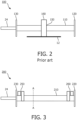
- the prior art drive train assembly 100 comprises a first end mount 120, which is driven by a motor (not shown).
- the drive train assembly also includes a second end mount 130. Extending from second end mount 130 is a drive shaft for connection of an attachment 14 (not shown).
- the nodally-mounted V-shaped torsion spring 110 is fixedly mounted at the respective ends thereof to end mount assemblies 120 and 130. At approximately the center point, which is node point 150, the torsion spring 110 is mounted via element 160 to the body 12.
- Element 160 may be, for example, a spring, fixed ring, or other linking component.
- the drive train assembly 200 comprises a first end mount 220, which is driven by a motor (not shown).
- the drive train assembly also includes a second end mount 230. Extending from second end mount 230 is a drive shaft 240 for connection of an attachment 14 (not shown).
- the spring 210 is mounted at the respective ends thereof to end mount assemblies 220 and 230. Unlike the prior art spring 110, spring 210 is not nodally mounted along its central length. Instead, the spring 210 comprises a X-shaped cross flexure spring hinge 250 and 260 on each end. Each of the cross flexures 250, 260 comprises two spring hinge leaflets attached at a respective end of the spring 210 to form an X-shape. This eliminates the need for a number of supporting components, as needed in the prior art.
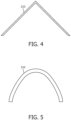
- FIG. 4 in one embodiment, is a cross-section of a V-shaped torsion spring 210 taken at axis A-A of FIG. 3 .
- FIG. 5 is a cross-section of a U-shaped spring 210 taken at axis A-A of FIG. 3 .
- Spring 210 can comprise many different shapes and sizes. Additionally, the spring can be composed of one or more materials providing sufficient resiliency, resistance to stress, and other desirable characteristics.
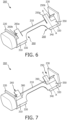
- a drive train assembly 200 with a non-nodally mounted torsion spring 210 comprises a first end mount 220, which is driven by a motor (not shown).
- the drive train assembly also includes a second end mount 230.
- the spring 210 is mounted at the respective ends thereof to end mount assemblies 220 and 230.
- the spring 210 comprises an X-shaped cross-flexure spring hinge 250 and 260 on each end.
- Each of the cross flexure spring hinges 250, 260 comprises two spring hinge leaflets 250a, 250b; 260a, 260b attached at one end to the spring 210 that form an X-shape.
- the two ends of the spring 210 can be fixed in place using any one of a variety of mechanisms.
- the two ends can be fixed in place with screws, bolts, or another fixing.
- the two ends of the spring can be fixed in place by welding the ends, such as by laser welding.
- the first end of the spring 210 can be welded or otherwise fixed to a support structure 330 at or along region 310.
- the second end of the spring 210 can be welded or otherwise fixed to a similar support structure 340 at or along region 320.
- the ends of the spring can be welded or otherwise fixed to the first and second end mount assemblies 220 and 230.
- the second end can be welded or fixed to second end mount assembly 230 at intersection point 350.
- the drive train assembly 200 comprises a first end mount 220, which is driven by a motor (not shown).
- the drive train assembly also includes a second end mount 230. Extending from second end mount 230 is a drive shaft 24(not shown) for an attachment.
- the spring 210 is mounted at the respective ends thereof to end mount assemblies 220 and 230.
- the drive train assembly comprises a cross flexure spring hinge 250 and 260 on each of the first support structure 330 and the second support structure 340.
- Each of the cross flexures 250, 260 comprises two spring hinge leaflets 250a, 250b; 260a, 260b (shown in FIG. 6 ) attached at one end to the spring 210 that form an X-shape.
- Each of the leaflets is attached to the respective support structure, and the attached end of each leaflet is spaced slightly from the spring 210 by a space 380, 390. This enables larger X-spring deflections, among other benefits.
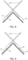
- FIGS. 8 and 9 are cross-sections of various embodiments of the drive train assembly 200, taken along axis A-A in FIGS. 6, 7 , or a similar embodiment of the assembly 200.
- the two spring hinge leaflets of the cross flexure spring hinge 250 are connected to and extend outwardly from the spring 210.
- the two spring leaflets of the cross flexure 250 are not directly connected to the second support structure 340, but are connected via spring 210, which is connected to the second support structure 340.
- the two spring leaflets of the cross flexure spring hinge 250 may be directly connected to both the spring 210 and the second support structure 340.
- FIG. 8 for example, the two spring hinge leaflets of the cross flexure spring hinge 250 are connected to and extend outwardly from the spring 210.
- the two spring leaflets of the cross flexure 250 are not directly connected to the second support structure 340, but are connected via spring 210, which is connected to the second support structure 340.
- the two spring hinge leaflets of the cross flexure spring hinge 250 are not directly connected to the spring 210, but are instead connected to the second support structure 340.
- a space 390 is located between the spring 210 and the cross flexure spring hinge 250.
- the drive train assembly 200 comprises a first end mount 220, which is driven by a motor (not shown).
- the drive train assembly also includes a second end mount 230. Extending from second end mount 230 is drive shaft 24for connecting an attachment 14.
- the spring 210 is mounted at the respective ends thereof to end mount assemblies 220 and 230.
- the spring 210 comprises an X-shaped cross flexure spring hinge 250 and 260 on each end.
- Each of the cross flexure spring hinges 250, 260 comprises two spring hinge leaflets 250a, 250b; 260a, 260b attached at one end of the spring 210 that form an X-shape.
- Surrounding the drive train assembly is an internal drive housing 270.
- the non-nodally mounted spring suspension system of the present invention is an improvement over the prior art system shown in FIG. 2 , which improvement reduces complexity of attachment, and provides more predictable behavior of the system.
- the system still enables 2-mode operation of the drive system, without the need for clamping of a nodal point for the second mode of operation.
- the drive system of the present invention reduces vibration and lack drive hysteresis, enabling easier amplitude and force sensing of the drive system. Because of the reduced complexity of the attachment, material stresses that can lead to premature breakage and drive hysteresis are drastically reduced. Additionally, reduced attachment complexity reduces the number of parts needed and manufacturing complexities and costs.
- the phrase "at least one,” in reference to a list of one or more elements, should be understood to mean at least one element selected from any one or more of the elements in the list of elements, but not necessarily including at least one of each and every element specifically listed within the list of elements and not excluding any combinations of elements in the list of elements.
- This definition also allows that elements may optionally be present other than the elements specifically identified within the list of elements to which the phrase "at least one" refers, whether related or unrelated to those elements specifically identified.
Landscapes
- Health & Medical Sciences (AREA)
- General Engineering & Computer Science (AREA)
- Engineering & Computer Science (AREA)
- Life Sciences & Earth Sciences (AREA)
- Animal Behavior & Ethology (AREA)
- General Health & Medical Sciences (AREA)
- Public Health (AREA)
- Veterinary Medicine (AREA)
- Epidemiology (AREA)
- Dentistry (AREA)
- Mechanical Engineering (AREA)
- Brushes (AREA)
- Transmission Devices (AREA)
Applications Claiming Priority (2)
| Application Number | Priority Date | Filing Date | Title |
|---|---|---|---|
| US201662393321P | 2016-09-12 | 2016-09-12 | |
| PCT/EP2017/072898 WO2018046760A1 (en) | 2016-09-12 | 2017-09-12 | Drive train assembly for a personal care device |
Publications (3)
| Publication Number | Publication Date |
|---|---|
| EP3509537A1 EP3509537A1 (en) | 2019-07-17 |
| EP3509537B1 true EP3509537B1 (en) | 2024-05-15 |
| EP3509537C0 EP3509537C0 (en) | 2024-05-15 |
Family
ID=59859083
Family Applications (1)
| Application Number | Title | Priority Date | Filing Date |
|---|---|---|---|
| EP17767812.5A Active EP3509537B1 (en) | 2016-09-12 | 2017-09-12 | Drive train assembly for a personal care device |
Country Status (6)
| Country | Link |
|---|---|
| US (1) | US11649860B2 (enExample) |
| EP (1) | EP3509537B1 (enExample) |
| JP (1) | JP7587919B2 (enExample) |
| CN (1) | CN109688969B (enExample) |
| RU (1) | RU2754064C2 (enExample) |
| WO (1) | WO2018046760A1 (enExample) |
Families Citing this family (4)
| Publication number | Priority date | Publication date | Assignee | Title |
|---|---|---|---|---|
| USD950729S1 (en) | 2019-09-30 | 2022-05-03 | Water Pik, Inc. | Toothbrush drive train |
| US11864965B2 (en) | 2019-09-30 | 2024-01-09 | Water Pik, Inc. | Electric toothbrush |
| EP4643762A1 (en) | 2024-05-01 | 2025-11-05 | Koninklijke Philips N.V. | Method for determining oral health |
| WO2026002705A1 (en) | 2024-06-25 | 2026-01-02 | Koninklijke Philips N.V. | Method to generate oral care advice |
Family Cites Families (26)
| Publication number | Priority date | Publication date | Assignee | Title |
|---|---|---|---|---|
| GB542131A (en) | 1940-05-10 | 1941-12-29 | Chicago Flexible Shaft Co | Vibratory electromagnetic motor |
| SU634026A1 (ru) * | 1973-03-20 | 1978-11-25 | Предприятие П/Я А-7526 | Пружинный крестообразный шарнир |
| JPH1184305A (ja) | 1997-09-09 | 1999-03-26 | N Ii C Sanei Kk | 光学走査装置 |
| US7067945B2 (en) | 2002-05-03 | 2006-06-27 | Koninklijke Philips Electronics N.V. | Apparatus for converting side-to-side driving motion to rotational motion with a spring assembly and system for tuning the spring assembly |
| US6833639B2 (en) * | 2002-12-23 | 2004-12-21 | Cyber Industrial Ltd. | Electric actuator |
| US7614107B2 (en) * | 2004-01-02 | 2009-11-10 | Sonicscrubbers, Llc | Cleaning apparatus with reciprocating brush head |
| US7157816B2 (en) * | 2004-06-22 | 2007-01-02 | Pacific Bioscience Laboratories, Inc. | Motor providing oscillating action for a personal care appliance |
| EP1834605A1 (de) | 2006-03-17 | 2007-09-19 | Trisa Holding AG | Elektrisch betriebenes, kontinuierlich einstellbares Körperpflegegerät |
| US9410593B2 (en) * | 2006-06-30 | 2016-08-09 | Koninklijke Philips N.V. | Nodal spring assembly for an electronic toothbrush |
| CN101479497B (zh) * | 2006-06-30 | 2012-12-05 | 皇家飞利浦电子股份有限公司 | 用于电动牙刷的节点弹簧组件 |
| US7786626B2 (en) * | 2006-11-03 | 2010-08-31 | Pacific Bioscience Laboratories, Inc. | Oscillating motor for a personal care appliance |
| WO2008053455A1 (en) * | 2006-11-03 | 2008-05-08 | Koninklijke Philips Electronics, N.V. | Vibration-canceling secondary resonator for use in a personal care appliance |
| US7779841B2 (en) * | 2006-11-13 | 2010-08-24 | Carefusion 2200, Inc. | Respiratory therapy device and method |
| DE102006061381A1 (de) * | 2006-12-23 | 2008-06-26 | Braun Gmbh | Antriebsvorrichtung zum Antreiben eines Bürstenelements einer elektrischen Zahnbürste |
| WO2010001196A1 (en) * | 2008-07-02 | 2010-01-07 | Koninklijke Philips Electronics N.V. | V-spring configuration and end attachment assemblies therefor for use in a personal care appliance |
| CA2730891A1 (en) * | 2008-08-20 | 2010-02-25 | Braun Gmbh | Electro-polymer motor |
| EP2246009A1 (en) * | 2009-05-02 | 2010-11-03 | Braun GmbH | Oscillatory system for a motorized drive unit |
| RU2550434C2 (ru) * | 2009-11-16 | 2015-05-10 | Конинклейке Филипс Электроникс Н.В. | Зубная щетка резонансного принципа действия с механическим приводом |
| CN102111032B (zh) | 2010-04-26 | 2012-12-05 | 王凤梅 | 电动牙刷高频振动电机 |
| EP2603165B1 (en) * | 2010-08-09 | 2018-02-21 | Koninklijke Philips N.V. | A flexible drive shaft for an eccentric weight-driven personal care appliance |
| EP2737619B1 (en) * | 2011-07-25 | 2017-08-23 | Braun GmbH | Oral care devices with linear electro-polymer motors |
| CN203106153U (zh) * | 2012-12-28 | 2013-08-07 | 卜祥森 | 一种便携牙膏牙刷组合体 |
| US9062736B2 (en) * | 2013-04-09 | 2015-06-23 | Koninklijke Philips N.V. | Nodal spring assembly for an electronic toothbrush |
| WO2015085033A1 (en) * | 2013-12-04 | 2015-06-11 | Ranir, Llc | Spring mechanism for power device drive unit |
| JP6665097B2 (ja) * | 2013-12-30 | 2020-03-13 | コーニンクレッカ フィリップス エヌ ヴェKoninklijke Philips N.V. | パーソナルケア器具のための群化磁石を備えるアクチュエータ |
| US11291294B1 (en) * | 2021-12-16 | 2022-04-05 | Shenzhen E-World Technology Limiied | Magnetically driven electric toothbrush head |
-
2017
- 2017-09-12 JP JP2019505041A patent/JP7587919B2/ja active Active
- 2017-09-12 CN CN201780055736.0A patent/CN109688969B/zh active Active
- 2017-09-12 WO PCT/EP2017/072898 patent/WO2018046760A1/en not_active Ceased
- 2017-09-12 US US16/332,266 patent/US11649860B2/en active Active
- 2017-09-12 RU RU2019110820A patent/RU2754064C2/ru active
- 2017-09-12 EP EP17767812.5A patent/EP3509537B1/en active Active
Also Published As
| Publication number | Publication date |
|---|---|
| WO2018046760A1 (en) | 2018-03-15 |
| RU2019110820A (ru) | 2020-10-12 |
| EP3509537C0 (en) | 2024-05-15 |
| JP2019532683A (ja) | 2019-11-14 |
| EP3509537A1 (en) | 2019-07-17 |
| JP7587919B2 (ja) | 2024-11-21 |
| RU2019110820A3 (enExample) | 2020-12-08 |
| US11649860B2 (en) | 2023-05-16 |
| RU2754064C2 (ru) | 2021-08-25 |
| US20190203775A1 (en) | 2019-07-04 |
| CN109688969A (zh) | 2019-04-26 |
| CN109688969B (zh) | 2022-04-08 |
Similar Documents
| Publication | Publication Date | Title |
|---|---|---|
| EP3509537B1 (en) | Drive train assembly for a personal care device | |
| EP3474775B1 (en) | Drive train assembly for an oral care device | |
| CN111655194A (zh) | 震动牙刷以及偏心轴 | |
| EP3509536B1 (en) | Drivetrain assembly for a personal care device | |
| KR20130056888A (ko) | 내파괴성 브러시 헤드 | |
| JP5768413B2 (ja) | 振動発生装置および電動歯ブラシ | |
| KR102594772B1 (ko) | 개인 케어 장치용 진동 제거 | |
| EP4432973B1 (en) | Drivetrain assemblies for generating sweeping motion and power tapping motion | |
| EP4432975B1 (en) | Resonator assembly and power toothbrush including such a resonator | |
| KR102406428B1 (ko) | 진동 칫솔 및 편심축 | |
| EP4432976A1 (en) | Drivetrain assemblies for generating power tapping motion using flexures |
Legal Events
| Date | Code | Title | Description |
|---|---|---|---|
| STAA | Information on the status of an ep patent application or granted ep patent |
Free format text: STATUS: UNKNOWN |
|
| STAA | Information on the status of an ep patent application or granted ep patent |
Free format text: STATUS: THE INTERNATIONAL PUBLICATION HAS BEEN MADE |
|
| PUAI | Public reference made under article 153(3) epc to a published international application that has entered the european phase |
Free format text: ORIGINAL CODE: 0009012 |
|
| STAA | Information on the status of an ep patent application or granted ep patent |
Free format text: STATUS: REQUEST FOR EXAMINATION WAS MADE |
|
| 17P | Request for examination filed |
Effective date: 20190412 |
|
| AK | Designated contracting states |
Kind code of ref document: A1 Designated state(s): AL AT BE BG CH CY CZ DE DK EE ES FI FR GB GR HR HU IE IS IT LI LT LU LV MC MK MT NL NO PL PT RO RS SE SI SK SM TR |
|
| AX | Request for extension of the european patent |
Extension state: BA ME |
|
| DAV | Request for validation of the european patent (deleted) | ||
| DAX | Request for extension of the european patent (deleted) | ||
| STAA | Information on the status of an ep patent application or granted ep patent |
Free format text: STATUS: EXAMINATION IS IN PROGRESS |
|
| RAP1 | Party data changed (applicant data changed or rights of an application transferred) |
Owner name: KONINKLIJKE PHILIPS N.V. |
|
| 17Q | First examination report despatched |
Effective date: 20200228 |
|
| GRAP | Despatch of communication of intention to grant a patent |
Free format text: ORIGINAL CODE: EPIDOSNIGR1 |
|
| STAA | Information on the status of an ep patent application or granted ep patent |
Free format text: STATUS: GRANT OF PATENT IS INTENDED |
|
| INTG | Intention to grant announced |
Effective date: 20231212 |
|
| GRAS | Grant fee paid |
Free format text: ORIGINAL CODE: EPIDOSNIGR3 |
|
| GRAA | (expected) grant |
Free format text: ORIGINAL CODE: 0009210 |
|
| STAA | Information on the status of an ep patent application or granted ep patent |
Free format text: STATUS: THE PATENT HAS BEEN GRANTED |
|
| AK | Designated contracting states |
Kind code of ref document: B1 Designated state(s): AL AT BE BG CH CY CZ DE DK EE ES FI FR GB GR HR HU IE IS IT LI LT LU LV MC MK MT NL NO PL PT RO RS SE SI SK SM TR |
|
| REG | Reference to a national code |
Ref country code: CH Ref legal event code: EP Ref country code: GB Ref legal event code: FG4D |
|
| REG | Reference to a national code |
Ref country code: DE Ref legal event code: R096 Ref document number: 602017081939 Country of ref document: DE |
|
| REG | Reference to a national code |
Ref country code: IE Ref legal event code: FG4D |
|
| U01 | Request for unitary effect filed |
Effective date: 20240515 |
|
| U07 | Unitary effect registered |
Designated state(s): AT BE BG DE DK EE FI FR IT LT LU LV MT NL PT SE SI Effective date: 20240524 |
|
| PG25 | Lapsed in a contracting state [announced via postgrant information from national office to epo] |
Ref country code: IS Free format text: LAPSE BECAUSE OF FAILURE TO SUBMIT A TRANSLATION OF THE DESCRIPTION OR TO PAY THE FEE WITHIN THE PRESCRIBED TIME-LIMIT Effective date: 20240915 |
|
| PG25 | Lapsed in a contracting state [announced via postgrant information from national office to epo] |
Ref country code: HR Free format text: LAPSE BECAUSE OF FAILURE TO SUBMIT A TRANSLATION OF THE DESCRIPTION OR TO PAY THE FEE WITHIN THE PRESCRIBED TIME-LIMIT Effective date: 20240515 |
|
| PG25 | Lapsed in a contracting state [announced via postgrant information from national office to epo] |
Ref country code: GR Free format text: LAPSE BECAUSE OF FAILURE TO SUBMIT A TRANSLATION OF THE DESCRIPTION OR TO PAY THE FEE WITHIN THE PRESCRIBED TIME-LIMIT Effective date: 20240816 |
|
| PG25 | Lapsed in a contracting state [announced via postgrant information from national office to epo] |
Ref country code: ES Free format text: LAPSE BECAUSE OF FAILURE TO SUBMIT A TRANSLATION OF THE DESCRIPTION OR TO PAY THE FEE WITHIN THE PRESCRIBED TIME-LIMIT Effective date: 20240515 |
|
| PG25 | Lapsed in a contracting state [announced via postgrant information from national office to epo] |
Ref country code: PL Free format text: LAPSE BECAUSE OF FAILURE TO SUBMIT A TRANSLATION OF THE DESCRIPTION OR TO PAY THE FEE WITHIN THE PRESCRIBED TIME-LIMIT Effective date: 20240515 |
|
| PG25 | Lapsed in a contracting state [announced via postgrant information from national office to epo] |
Ref country code: PL Free format text: LAPSE BECAUSE OF FAILURE TO SUBMIT A TRANSLATION OF THE DESCRIPTION OR TO PAY THE FEE WITHIN THE PRESCRIBED TIME-LIMIT Effective date: 20240515 Ref country code: NO Free format text: LAPSE BECAUSE OF FAILURE TO SUBMIT A TRANSLATION OF THE DESCRIPTION OR TO PAY THE FEE WITHIN THE PRESCRIBED TIME-LIMIT Effective date: 20240815 Ref country code: IS Free format text: LAPSE BECAUSE OF FAILURE TO SUBMIT A TRANSLATION OF THE DESCRIPTION OR TO PAY THE FEE WITHIN THE PRESCRIBED TIME-LIMIT Effective date: 20240915 Ref country code: HR Free format text: LAPSE BECAUSE OF FAILURE TO SUBMIT A TRANSLATION OF THE DESCRIPTION OR TO PAY THE FEE WITHIN THE PRESCRIBED TIME-LIMIT Effective date: 20240515 Ref country code: GR Free format text: LAPSE BECAUSE OF FAILURE TO SUBMIT A TRANSLATION OF THE DESCRIPTION OR TO PAY THE FEE WITHIN THE PRESCRIBED TIME-LIMIT Effective date: 20240816 Ref country code: ES Free format text: LAPSE BECAUSE OF FAILURE TO SUBMIT A TRANSLATION OF THE DESCRIPTION OR TO PAY THE FEE WITHIN THE PRESCRIBED TIME-LIMIT Effective date: 20240515 Ref country code: RS Free format text: LAPSE BECAUSE OF FAILURE TO SUBMIT A TRANSLATION OF THE DESCRIPTION OR TO PAY THE FEE WITHIN THE PRESCRIBED TIME-LIMIT Effective date: 20240815 |
|
| U20 | Renewal fee for the european patent with unitary effect paid |
Year of fee payment: 8 Effective date: 20240930 |
|
| PG25 | Lapsed in a contracting state [announced via postgrant information from national office to epo] |
Ref country code: CZ Free format text: LAPSE BECAUSE OF FAILURE TO SUBMIT A TRANSLATION OF THE DESCRIPTION OR TO PAY THE FEE WITHIN THE PRESCRIBED TIME-LIMIT Effective date: 20240515 |
|
| PG25 | Lapsed in a contracting state [announced via postgrant information from national office to epo] |
Ref country code: SK Free format text: LAPSE BECAUSE OF FAILURE TO SUBMIT A TRANSLATION OF THE DESCRIPTION OR TO PAY THE FEE WITHIN THE PRESCRIBED TIME-LIMIT Effective date: 20240515 Ref country code: RO Free format text: LAPSE BECAUSE OF FAILURE TO SUBMIT A TRANSLATION OF THE DESCRIPTION OR TO PAY THE FEE WITHIN THE PRESCRIBED TIME-LIMIT Effective date: 20240515 |
|
| PG25 | Lapsed in a contracting state [announced via postgrant information from national office to epo] |
Ref country code: SM Free format text: LAPSE BECAUSE OF FAILURE TO SUBMIT A TRANSLATION OF THE DESCRIPTION OR TO PAY THE FEE WITHIN THE PRESCRIBED TIME-LIMIT Effective date: 20240515 |
|
| PG25 | Lapsed in a contracting state [announced via postgrant information from national office to epo] |
Ref country code: SM Free format text: LAPSE BECAUSE OF FAILURE TO SUBMIT A TRANSLATION OF THE DESCRIPTION OR TO PAY THE FEE WITHIN THE PRESCRIBED TIME-LIMIT Effective date: 20240515 Ref country code: SK Free format text: LAPSE BECAUSE OF FAILURE TO SUBMIT A TRANSLATION OF THE DESCRIPTION OR TO PAY THE FEE WITHIN THE PRESCRIBED TIME-LIMIT Effective date: 20240515 Ref country code: RO Free format text: LAPSE BECAUSE OF FAILURE TO SUBMIT A TRANSLATION OF THE DESCRIPTION OR TO PAY THE FEE WITHIN THE PRESCRIBED TIME-LIMIT Effective date: 20240515 Ref country code: CZ Free format text: LAPSE BECAUSE OF FAILURE TO SUBMIT A TRANSLATION OF THE DESCRIPTION OR TO PAY THE FEE WITHIN THE PRESCRIBED TIME-LIMIT Effective date: 20240515 |
|
| REG | Reference to a national code |
Ref country code: DE Ref legal event code: R097 Ref document number: 602017081939 Country of ref document: DE |
|
| PLBE | No opposition filed within time limit |
Free format text: ORIGINAL CODE: 0009261 |
|
| STAA | Information on the status of an ep patent application or granted ep patent |
Free format text: STATUS: NO OPPOSITION FILED WITHIN TIME LIMIT |
|
| 26N | No opposition filed |
Effective date: 20250218 |
|
| PG25 | Lapsed in a contracting state [announced via postgrant information from national office to epo] |
Ref country code: MC Free format text: LAPSE BECAUSE OF FAILURE TO SUBMIT A TRANSLATION OF THE DESCRIPTION OR TO PAY THE FEE WITHIN THE PRESCRIBED TIME-LIMIT Effective date: 20240515 |
|
| REG | Reference to a national code |
Ref country code: CH Ref legal event code: PL |
|
| PG25 | Lapsed in a contracting state [announced via postgrant information from national office to epo] |
Ref country code: CH Free format text: LAPSE BECAUSE OF NON-PAYMENT OF DUE FEES Effective date: 20240930 |
|
| PG25 | Lapsed in a contracting state [announced via postgrant information from national office to epo] |
Ref country code: IE Free format text: LAPSE BECAUSE OF NON-PAYMENT OF DUE FEES Effective date: 20240912 |
|
| PGFP | Annual fee paid to national office [announced via postgrant information from national office to epo] |
Ref country code: GB Payment date: 20250923 Year of fee payment: 9 |
|
| U20 | Renewal fee for the european patent with unitary effect paid |
Year of fee payment: 9 Effective date: 20250930 |
|
| PG25 | Lapsed in a contracting state [announced via postgrant information from national office to epo] |
Ref country code: CY Free format text: LAPSE BECAUSE OF FAILURE TO SUBMIT A TRANSLATION OF THE DESCRIPTION OR TO PAY THE FEE WITHIN THE PRESCRIBED TIME-LIMIT; INVALID AB INITIO Effective date: 20170912 |
|
| PG25 | Lapsed in a contracting state [announced via postgrant information from national office to epo] |
Ref country code: HU Free format text: LAPSE BECAUSE OF FAILURE TO SUBMIT A TRANSLATION OF THE DESCRIPTION OR TO PAY THE FEE WITHIN THE PRESCRIBED TIME-LIMIT; INVALID AB INITIO Effective date: 20170912 |