EP3474775B1 - Drive train assembly for an oral care device - Google Patents
Drive train assembly for an oral care device Download PDFInfo
- Publication number
- EP3474775B1 EP3474775B1 EP17728868.5A EP17728868A EP3474775B1 EP 3474775 B1 EP3474775 B1 EP 3474775B1 EP 17728868 A EP17728868 A EP 17728868A EP 3474775 B1 EP3474775 B1 EP 3474775B1
- Authority
- EP
- European Patent Office
- Prior art keywords
- leaf spring
- drive train
- train assembly
- spring assemblies
- care device
- Prior art date
- Legal status (The legal status is an assumption and is not a legal conclusion. Google has not performed a legal analysis and makes no representation as to the accuracy of the status listed.)
- Active
Links
- 230000000712 assembly Effects 0.000 claims description 41
- 238000000429 assembly Methods 0.000 claims description 41
- 238000010146 3D printing Methods 0.000 claims description 5
- 230000005540 biological transmission Effects 0.000 claims description 5
- RTAQQCXQSZGOHL-UHFFFAOYSA-N Titanium Chemical compound [Ti] RTAQQCXQSZGOHL-UHFFFAOYSA-N 0.000 claims description 4
- 239000010936 titanium Substances 0.000 claims description 4
- 229910052719 titanium Inorganic materials 0.000 claims description 4
- 230000033001 locomotion Effects 0.000 description 7
- 210000003128 head Anatomy 0.000 description 6
- 230000001680 brushing effect Effects 0.000 description 5
- 229910052751 metal Inorganic materials 0.000 description 5
- 239000002184 metal Substances 0.000 description 5
- 238000004140 cleaning Methods 0.000 description 4
- 238000013016 damping Methods 0.000 description 4
- 238000004519 manufacturing process Methods 0.000 description 4
- 239000000463 material Substances 0.000 description 3
- 238000000034 method Methods 0.000 description 3
- 238000010276 construction Methods 0.000 description 2
- 230000009286 beneficial effect Effects 0.000 description 1
- 230000001413 cellular effect Effects 0.000 description 1
- 238000004891 communication Methods 0.000 description 1
- 230000037123 dental health Effects 0.000 description 1
- 230000006870 function Effects 0.000 description 1
- 230000007774 longterm Effects 0.000 description 1
- 238000012986 modification Methods 0.000 description 1
- 230000004048 modification Effects 0.000 description 1
- 210000000214 mouth Anatomy 0.000 description 1
- 229920000642 polymer Polymers 0.000 description 1
- 230000004044 response Effects 0.000 description 1
- 239000007787 solid Substances 0.000 description 1
- 238000003860 storage Methods 0.000 description 1
Images

Classifications
-
- A—HUMAN NECESSITIES
- A61—MEDICAL OR VETERINARY SCIENCE; HYGIENE
- A61C—DENTISTRY; APPARATUS OR METHODS FOR ORAL OR DENTAL HYGIENE
- A61C17/00—Devices for cleaning, polishing, rinsing or drying teeth, teeth cavities or prostheses; Saliva removers; Dental appliances for receiving spittle
- A61C17/16—Power-driven cleaning or polishing devices
- A61C17/22—Power-driven cleaning or polishing devices with brushes, cushions, cups, or the like
- A61C17/32—Power-driven cleaning or polishing devices with brushes, cushions, cups, or the like reciprocating or oscillating
- A61C17/34—Power-driven cleaning or polishing devices with brushes, cushions, cups, or the like reciprocating or oscillating driven by electric motor
-
- A—HUMAN NECESSITIES
- A61—MEDICAL OR VETERINARY SCIENCE; HYGIENE
- A61C—DENTISTRY; APPARATUS OR METHODS FOR ORAL OR DENTAL HYGIENE
- A61C13/00—Dental prostheses; Making same
- A61C13/34—Making or working of models, e.g. preliminary castings, trial dentures; Dowel pins [4]
-
- A—HUMAN NECESSITIES
- A61—MEDICAL OR VETERINARY SCIENCE; HYGIENE
- A61C—DENTISTRY; APPARATUS OR METHODS FOR ORAL OR DENTAL HYGIENE
- A61C17/00—Devices for cleaning, polishing, rinsing or drying teeth, teeth cavities or prostheses; Saliva removers; Dental appliances for receiving spittle
- A61C17/16—Power-driven cleaning or polishing devices
- A61C17/22—Power-driven cleaning or polishing devices with brushes, cushions, cups, or the like
- A61C17/32—Power-driven cleaning or polishing devices with brushes, cushions, cups, or the like reciprocating or oscillating
- A61C17/34—Power-driven cleaning or polishing devices with brushes, cushions, cups, or the like reciprocating or oscillating driven by electric motor
- A61C17/3409—Power-driven cleaning or polishing devices with brushes, cushions, cups, or the like reciprocating or oscillating driven by electric motor characterized by the movement of the brush body
- A61C17/3481—Vibrating brush body, e.g. by using eccentric weights
-
- A—HUMAN NECESSITIES
- A46—BRUSHWARE
- A46B—BRUSHES
- A46B2200/00—Brushes characterized by their functions, uses or applications
- A46B2200/10—For human or animal care
- A46B2200/1066—Toothbrush for cleaning the teeth or dentures
-
- A—HUMAN NECESSITIES
- A46—BRUSHWARE
- A46B—BRUSHES
- A46B5/00—Brush bodies; Handles integral with brushware
- A46B5/0095—Removable or interchangeable brush heads
-
- A—HUMAN NECESSITIES
- A61—MEDICAL OR VETERINARY SCIENCE; HYGIENE
- A61C—DENTISTRY; APPARATUS OR METHODS FOR ORAL OR DENTAL HYGIENE
- A61C17/00—Devices for cleaning, polishing, rinsing or drying teeth, teeth cavities or prostheses; Saliva removers; Dental appliances for receiving spittle
- A61C17/16—Power-driven cleaning or polishing devices
- A61C17/22—Power-driven cleaning or polishing devices with brushes, cushions, cups, or the like
- A61C17/221—Control arrangements therefor
-
- A—HUMAN NECESSITIES
- A61—MEDICAL OR VETERINARY SCIENCE; HYGIENE
- A61C—DENTISTRY; APPARATUS OR METHODS FOR ORAL OR DENTAL HYGIENE
- A61C17/00—Devices for cleaning, polishing, rinsing or drying teeth, teeth cavities or prostheses; Saliva removers; Dental appliances for receiving spittle
- A61C17/16—Power-driven cleaning or polishing devices
- A61C17/22—Power-driven cleaning or polishing devices with brushes, cushions, cups, or the like
- A61C17/222—Brush body details, e.g. the shape thereof or connection to handle
-
- F—MECHANICAL ENGINEERING; LIGHTING; HEATING; WEAPONS; BLASTING
- F16—ENGINEERING ELEMENTS AND UNITS; GENERAL MEASURES FOR PRODUCING AND MAINTAINING EFFECTIVE FUNCTIONING OF MACHINES OR INSTALLATIONS; THERMAL INSULATION IN GENERAL
- F16F—SPRINGS; SHOCK-ABSORBERS; MEANS FOR DAMPING VIBRATION
- F16F1/00—Springs
- F16F1/02—Springs made of steel or other material having low internal friction; Wound, torsion, leaf, cup, ring or the like springs, the material of the spring not being relevant
- F16F1/14—Torsion springs consisting of bars or tubes
Definitions
- the present disclosure is directed generally to a personal care device drive train arrangement having multiple leaf springs.
- Proper tooth brushing helps ensure long-term dental health. Many dental problems are experienced by individuals who either do not regularly brush their teeth or who do so inadequately, especially in a particular area or region of the oral cavity. Among individuals who do brush regularly, improper brushing habits can result in poor coverage of brushing and thus surfaces that are not adequately cleaned during a cleaning session, even when a standard brushing regimen is followed. Electric cleaning devices, such as electric toothbrushes, have been shown to greatly increase the efficacy of a cleaning session.
- These electric cleaning devices including power toothbrushes, shavers, and similar devices, have a motor, such as a mechanical, electromechanical, magnetic motor, that engages a drive train in order to drive a brushhead in an oscillating, reciprocating, or other pattern.
- a motor such as a mechanical, electromechanical, magnetic motor
- One type of drive train arrangement uses a spring mounted at both ends. Some configurations have a node point located approximately mid-length between the two ends, and some springs have a V-shape.
- EP1734889 discloses a head portion of a nodally mounted rotating toothbrush.
- the head portion includes a spring assembly, having two spring sections, the spring assembly having a node point between the two ends and a nodal mount member at the node point which is connected to a cover member of the head portion.
- a driving assembly is arranged to drive the first spring section, the second section rotating in an opposing direction from the first spring section, the second spring section having a drive shaft extending therefrom, upon a free end of which a brushhead is mounted.
- WO 2009/156886 discloses a linear bearing for use in a personal care appliance.
- the bearing includes an elongated center member having end elements at each end thereof, the center member having an arm with a workpiece at the free end thereof.
- Two sets of orthogonal leaf springs are positioned in the vicinity of the ends of the center assembly, one end of each leaf spring in each set connected to an associated end member, the other end of each leaf spring in each set connected to a fixed-position member, such as the housing of the appliance.
- inventive drive train assemblies comprising a plurality of integrated leaf springs.
- inventive systems Applied to an electric or power personal care device such as an electric toothbrush or shaver, the inventive systems provide a one-or two-piece drive train assembly that is more efficient and more resistant to stress.
- the drive train assembly features 3D-printed metal construction with three elongated leaf springs and a fixed, centrally-located ring.
- a drive train assembly for an oral care device includes: a plurality of elongated leaf springs symmetrically disposed around the circumference of the drive train assembly, each of the plurality of elongated leaf springs secured at both ends; and a ring encircling the plurality of elongated leaf springs, wherein the ring is fixedly connected to each of the plurality of elongated leaf springs and fixedly connected to the housing of the oral care device.
- the drive train assembly further comprises a first end mount and a second end mount, wherein the plurality of elongated leaf springs are secured at a first end to the first end mount and at a second end to the second end mount.
- the drive train assembly further comprises a mount configured to engage a brushhead assembly.
- the ring is fixedly connected to each of the plurality of elongated leaf springs at approximately the middle of the length of each leaf spring.
- the drive train assembly comprises three symmetrical leaf spring assemblies.
- the plurality of elongated leaf springs comprises titanium.
- the drive train assembly comprises a single integral component manufactured by 3D printing.
- an oral care device includes a housing, and a drive train assembly comprising a plurality of elongated leaf springs symmetrically disposed around the circumference of the drive train assembly, each of the plurality of elongated leaf springs secured at both ends; and a ring encircling the plurality of elongated leaf springs, wherein the ring is fixedly connected to each of the plurality of elongated leaf springs and fixedly connected to the housing of the oral care device.
- a 3D-printed drive train assembly for an oral care device.
- the 3D-printed drive train assembly includes: a plurality of elongated leaf springs symmetrically disposed around the circumference of the drive train assembly, each of the plurality of elongated leaf springs secured at both ends; a first end mount and a second end mount, wherein the plurality of elongated leaf springs are secured at a first end to the first end mount and at a second end to the second end mount; a brushhead mount extending from the second end mount and configured to engage a brushhead assembly; and a ring encircling the plurality of elongated leaf springs, wherein the ring is fixedly connected to each of the plurality of elongated leaf springs at approximately the middle of the length of each leaf spring, and is further fixedly connected to the housing of the oral care device.
- the present disclosure describes various embodiments of a device for a drive train assembly for an electric personal care device. More generally, Applicant has recognized and appreciated that it would be beneficial to provide a one-or two-piece spring assembly that is more efficient and more resistant to stress. Accordingly, the systems described or otherwise envisioned herein provide a personal care device, such as an electric toothbrush or shaver, with a drive train spring assembly comprising multiple leaf springs surrounded by a fixed, centrally-located ring. According to an embodiment, the drive train spring assembly features 3D-printed metal construction.
- a particular goal of utilization of the embodiments and implementations herein is to provide a drive train spring assembly for an oral care device such as, e.g., a Philips SonicareTM toothbrush (manufactured by Koninklijke Philips Electronics, N.V.), although the assembly may be utilized with many other personal care devices.
- an oral care device such as, e.g., a Philips SonicareTM toothbrush (manufactured by Koninklijke Philips Electronics, N.V.), although the assembly may be utilized with many other personal care devices.
- an oral care device 10 includes a body portion housing 12 and a brush head member 14 mounted on the body portion.
- Brush head member 14 includes at its end remote from the body portion a brush head 16.
- Brush head 16 includes a bristle face 18, which provides a plurality of bristles.
- the bristles extend along an axis substantially perpendicular to the head's axis of elongation, although many other embodiments of the brush head and bristles are possible.
- Head member 14 is mounted so as to be able to move relative to the body portion housing 12.
- the movement can be any of a variety of different movements, including vibrations or rotation, among others.
- head member 14 is mounted to the body so as to be able to vibrate relative to body portion housing 12, or, as another example, brush head 16 is mounted to head member 14 so as to be able to vibrate relative to body portion housing 12.
- the brush head member 14 can be fixedly mounted onto body portion housing 12, or it may alternatively be detachably mounted so that head member 14 can be replaced with a new one when the bristles or another component of the device are worn out and require replacement.
- the body portion housing 12 incorporates a drive train 22 for generating movement and a transmission component 24 for transmitting the generated movements to brush head member 14.
- drive train 22 comprises a motor or electromagnet(s) that generates movement of a spring assembly, which is subsequently transmitted to the brush head member 14.
- Drive train 22 can include components such as a power supply, an oscillator, and one or more electromagnets, among other components.
- the power supply comprises one or more rechargeable batteries, not shown, which can, for example, be electrically charged in a charging holder in which oral care device 10 is placed when not in use.
- the body portion housing 12 is further provided with a user input 26 to activate and deactivate drive train 22.
- the user input 26 allows a user to operate the oral care device 10 for example to turn the oral care device 10 on and off.
- the user input 26 may, for example, be a button, touch screen, or switch.
- the body portion housing of the device also comprises a controller 30.
- Controller 30 may be formed of one or multiple modules, and is configured to operate the oral care device 10 in response to an input, such as input obtained via user input 26.
- Controller 30 can comprise, for example, a processor 32 and a memory 34, and can optionally include a connectivity module 38.
- the processor 32 may take any suitable form, including but not limited to a microcontroller, multiple microcontrollers, circuitry, a single processor, or plural processors.
- the memory 34 can take any suitable form, including a non-volatile memory and/or RAM.
- the non-volatile memory may include read only memory (ROM), a hard disk drive (HDD), or a solid state drive (SSD).
- the memory can store, among other things, an operating system.
- the RAM is used by the processor for the temporary storage of data.
- an operating system may contain code which, when executed by controller 30, controls operation of the hardware components of oral care device 10.
- connectivity module 38 transmits collected sensor data, and can be any module, device, or means capable of transmitting a wired or wireless signal, including but not limited to a Wi-Fi, Bluetooth, near field communication, and/or cellular module.
- the drive train assembly 22 comprises a first end mount 44, which is driven by a motor (not shown).
- the drive train assembly also includes a second end mount 48. Extending from end mount 48 is a transmission component 24 for attaching a head member 14.
- a series of leaf spring assemblies 50 are fixedly mounted at the respective ends thereof to end mounts 44 and 48. Mounted to approximately the center point (node point) of the leaf spring assemblies 50 is a fixed ring 46, which is fixedly attached to the housing 12 of the oral care device at one or more of its outer edges thereof.
- a drive train assembly 22 with a leaf spring region 40 is a drive train assembly 22 with a leaf spring region 40.
- Three leaf spring assemblies 50 A, B, and C are arranged lengthwise around the circumference of the drive train assembly 22.
- a fixed ring 46 is mounted to approximately the center point (node point) of the leaf spring assemblies 50.
- a cross-section of the drive train assembly 22 is taken at three different points 1, 2, and 3 corresponding to Section 1, Section 2, and Section 3 in FIG. 3 , respectively.
- the cross-sections display the arrangement of the leaf spring assemblies 50 and fixed ring 46 around the circumference of the drive train assembly 22 at each of Section points 1, 2, and 3, respectively.
- the leaf spring region 40 is symmetrical around the circumference of drive train assembly 22, as shown in FIGS. 3 and 5 .
- each of the leaf spring assemblies 50 along their length is shown in FIG. 4 according to one embodiment, where each leaf spring is attached at a first end mount 44 and a second end mount 48 of the drive train assembly 22.
- the leaf spring assemblies can be much longer than traditional leaf springs in power toothbrush spring assemblies.
- the leaf spring assemblies 50 depicted in FIG. 3 can be as much as 2.5 times longer than the traditional leaf springs.
- leaf spring assemblies 50 in FIGS. 2-4 are depicted as being substantially straight, they can also be any shape.
- one or more of the leaf spring assemblies 50 as described or otherwise envisioned herein can be straight, curved, curvilinear, and/or any other shape.
- the leaf spring assemblies 50 can be of the same or variable thickness along their length.
- the leaf spring assemblies 50 can be, for example, a single thickness of approximately 0.35 to 0.50 mm over their length, but they can also comprise a variety of different thicknesses along their length.
- each leaf spring assembly 50 comprises a leaf spring 50 with a first segment 50' and a second segment 50".
- Each leaf spring assembly 50 also comprises a connection to the fixed ring 46.
- FIG. 6 in one embodiment, is a cross-section at Section point 2 of the drive train assembly 22 from FIGS. 3 and 4 upon rotation of the drive train.
- the fixed ring 46 is fixed and stationary, and the leaf spring assemblies 50 flex until metal-to-metal contact causes the rotation to stop, as shown in FIG. 6 .
- FIGS. 7 and 8 is a cross-section of another configuration of drive train assembly 22.
- This drive train assembly comprises a different configuration, although in this embodiment the leaf spring region 40 is symmetrical and comprises leaf spring assembly 50A, leaf spring assembly 50B, and leaf spring assembly 50C, where each is approximately 120 degrees.
- Each of the leaf spring assemblies comprises a leaf spring member50 with a first segment 50', a second segment 50", and a third segment 50′′′.
- Each leaf spring assembly 50 also comprises a connection to the fixed ring 46.
- FIG. 8 is a cross-section of the drive train assembly 22 from FIG. 7 upon rotation of the drive train.
- the fixed ring 46 is fixed and stationary, and the leaf spring assemblies 50 flex until metal-to-metal contact causes the rotation to stop, according to an embodiment.
- the frequency mode of the drive train assembly 22 may comprise small peaks, which may result in negative or undesirable vibrations within or on the oral care device 10. These undesirable vibrations can affect the functioning of the drive train assembly 22 and the functioning of the oral care device 10, and can significantly lower the lifespan and/or efficiency of the oral care device.
- the drive train assembly 22 and/or oral care device can comprise a damping gel.
- the damping gel can be any gel or polymer suitable to reduce, absorb, or otherwise minimize vibrations or other undesirable movement or motion of the leaf springs or other components of the oral care device.
- one or both ends of the leaf springs 50 comprise a damping gel component.
- the first and/or second end of the one or more leaf springs can comprise a gel holder filled with a damping gel configured and positioned to at least partially resolve the undesirable vibrations of the drive train assembly 22.
- the drive train assembly 22 is manufactured using a 3D printing technique.
- the 3D printing method reduces the number of parts in the drive train assembly 22 from as many as 18 to as few as one or two, thereby reducing cost and manufacturing time while increasing durability and reliability.
- the drive train assembly 22 can be manufactured from a wide variety of materials, including but not limited to plastic, metal, and combinations thereof.
- the drive train assembly 22 is composed in part or in whole of titanium in order to provide sufficient resilience and durability.
- the drive train assembly 22 can be manufactured using a printer which prints in one or more 2D layers, for example. Many other methods of manufacture are possible.
- the phrase "at least one,” in reference to a list of one or more elements, should be understood to mean at least one element selected from any one or more of the elements in the list of elements, but not necessarily including at least one of each and every element specifically listed within the list of elements and not excluding any combinations of elements in the list of elements.
- This definition also allows that elements may optionally be present other than the elements specifically identified within the list of elements to which the phrase "at least one" refers, whether related or unrelated to those elements specifically identified.
Description
- The present disclosure is directed generally to a personal care device drive train arrangement having multiple leaf springs.
- Proper tooth brushing, including length and coverage of brushing, helps ensure long-term dental health. Many dental problems are experienced by individuals who either do not regularly brush their teeth or who do so inadequately, especially in a particular area or region of the oral cavity. Among individuals who do brush regularly, improper brushing habits can result in poor coverage of brushing and thus surfaces that are not adequately cleaned during a cleaning session, even when a standard brushing regimen is followed. Electric cleaning devices, such as electric toothbrushes, have been shown to greatly increase the efficacy of a cleaning session.
- These electric cleaning devices, including power toothbrushes, shavers, and similar devices, have a motor, such as a mechanical, electromechanical, magnetic motor, that engages a drive train in order to drive a brushhead in an oscillating, reciprocating, or other pattern. One type of drive train arrangement uses a spring mounted at both ends. Some configurations have a node point located approximately mid-length between the two ends, and some springs have a V-shape.
- These spring arrangements, however, are prone to failure as a result of fretting fatigue in which repeated forces at the interface of the clamped ends of the spring causes stresses on the spring and clamp. Over time, this can lead to failure of one or more of the parts. Additionally, spring arrangements where the spring is mounted at both ends requires numerous different parts, which increases component costs, manufacturing costs, and production time.
- Accordingly, there is a continued need for personal care device drive trains arrangements having fewer parts and including an integrated leaf spring assembly, resulting in increased resilience to stress and fatigue.
-
EP1734889 discloses a head portion of a nodally mounted rotating toothbrush. The head portion includes a spring assembly, having two spring sections, the spring assembly having a node point between the two ends and a nodal mount member at the node point which is connected to a cover member of the head portion. A driving assembly is arranged to drive the first spring section, the second section rotating in an opposing direction from the first spring section, the second spring section having a drive shaft extending therefrom, upon a free end of which a brushhead is mounted. When the head portion is removed from the handle, the spring assembly is removed therewith. -
WO 2009/156886 discloses a linear bearing for use in a personal care appliance. The bearing includes an elongated center member having end elements at each end thereof, the center member having an arm with a workpiece at the free end thereof. Two sets of orthogonal leaf springs are positioned in the vicinity of the ends of the center assembly, one end of each leaf spring in each set connected to an associated end member, the other end of each leaf spring in each set connected to a fixed-position member, such as the housing of the appliance. - The present disclosure is directed to inventive drive train assemblies comprising a plurality of integrated leaf springs. Applied to an electric or power personal care device such as an electric toothbrush or shaver, the inventive systems provide a one-or two-piece drive train assembly that is more efficient and more resistant to stress. The drive train assembly features 3D-printed metal construction with three elongated leaf springs and a fixed, centrally-located ring.
- Generally in one aspect of the invention, as defined in
claim 1, a drive train assembly for an oral care device is provided. The drive train assembly includes: a plurality of elongated leaf springs symmetrically disposed around the circumference of the drive train assembly, each of the plurality of elongated leaf springs secured at both ends; and a ring encircling the plurality of elongated leaf springs, wherein the ring is fixedly connected to each of the plurality of elongated leaf springs and fixedly connected to the housing of the oral care device. - The drive train assembly further comprises a first end mount and a second end mount, wherein the plurality of elongated leaf springs are secured at a first end to the first end mount and at a second end to the second end mount.
- According to an embodiment, the drive train assembly further comprises a mount configured to engage a brushhead assembly.
- According to an embodiment, the ring is fixedly connected to each of the plurality of elongated leaf springs at approximately the middle of the length of each leaf spring.
- According to an embodiment, the drive train assembly comprises three symmetrical leaf spring assemblies.
- According to an embodiment, the plurality of elongated leaf springs comprises titanium.
- According to an embodiment, the drive train assembly comprises a single integral component manufactured by 3D printing.
- According to an aspect of the invention, as defined in claim 7, an oral care device is provided. The oral care device includes a housing, and a drive train assembly comprising a plurality of elongated leaf springs symmetrically disposed around the circumference of the drive train assembly, each of the plurality of elongated leaf springs secured at both ends; and a ring encircling the plurality of elongated leaf springs, wherein the ring is fixedly connected to each of the plurality of elongated leaf springs and fixedly connected to the housing of the oral care device.
- According to an aspect of the invention, as defined in claim 13, a 3D-printed drive train assembly for an oral care device is provided. The 3D-printed drive train assembly includes: a plurality of elongated leaf springs symmetrically disposed around the circumference of the drive train assembly, each of the plurality of elongated leaf springs secured at both ends; a first end mount and a second end mount, wherein the plurality of elongated leaf springs are secured at a first end to the first end mount and at a second end to the second end mount; a brushhead mount extending from the second end mount and configured to engage a brushhead assembly; and a ring encircling the plurality of elongated leaf springs, wherein the ring is fixedly connected to each of the plurality of elongated leaf springs at approximately the middle of the length of each leaf spring, and is further fixedly connected to the housing of the oral care device.
- It should be appreciated that all combinations of the foregoing concepts and additional concepts discussed in greater detail below (provided such concepts are not mutually inconsistent) are contemplated as being part of the inventive subject matter disclosed herein, the scope of the invention being defined by the appended appended claims.
- These and other aspects of the invention will be apparent from and elucidated with reference to the embodiment(s) described hereinafter.
- In the drawings, like reference characters generally refer to the same parts throughout the different views. Also, the drawings are not necessarily to scale, emphasis instead generally being placed upon illustrating the principles of the invention.
-
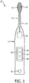
FIG. 1 is a schematic representation of an oral care device, in accordance with an embodiment. -
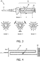
FIG. 2 is a schematic representation of a drive train assembly of an oral care device, in accordance with an embodiment. -
FIG. 3 is a schematic representation of a drive train assembly of an oral care device, with cross-sectional views, in accordance with an embodiment. -
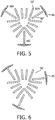
FIG. 4 is a schematic representation of a leaf spring for the drive train assembly of an oral care device, in accordance with an embodiment. -
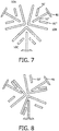
FIG. 5 is a schematic representation of a cross-section of a drive train assembly of an oral care device, in accordance with an embodiment. -
FIG. 6 is a schematic representation of a cross-section of a drive train assembly of an oral care device, in accordance with an embodiment. -
FIG. 7 is a schematic representation of a cross-section of a drive train assembly of an oral care device, in accordance with an embodiment. -
FIG. 8 is a schematic representation of a cross-section of a drive train assembly of an oral care device, in accordance with an embodiment - The present disclosure describes various embodiments of a device for a drive train assembly for an electric personal care device. More generally, Applicant has recognized and appreciated that it would be beneficial to provide a one-or two-piece spring assembly that is more efficient and more resistant to stress. Accordingly, the systems described or otherwise envisioned herein provide a personal care device, such as an electric toothbrush or shaver, with a drive train spring assembly comprising multiple leaf springs surrounded by a fixed, centrally-located ring. According to an embodiment, the drive train spring assembly features 3D-printed metal construction.
- A particular goal of utilization of the embodiments and implementations herein is to provide a drive train spring assembly for an oral care device such as, e.g., a Philips Sonicare™ toothbrush (manufactured by Koninklijke Philips Electronics, N.V.), although the assembly may be utilized with many other personal care devices.
- Referring to
FIG. 1 , in one embodiment, anoral care device 10 is provided that includes a body portion housing 12 and abrush head member 14 mounted on the body portion.Brush head member 14 includes at its end remote from the body portion abrush head 16.Brush head 16 includes abristle face 18, which provides a plurality of bristles. According to an embodiment, the bristles extend along an axis substantially perpendicular to the head's axis of elongation, although many other embodiments of the brush head and bristles are possible. -
Head member 14 is mounted so as to be able to move relative to thebody portion housing 12. The movement can be any of a variety of different movements, including vibrations or rotation, among others. According to one embodiment,head member 14 is mounted to the body so as to be able to vibrate relative tobody portion housing 12, or, as another example,brush head 16 is mounted tohead member 14 so as to be able to vibrate relative tobody portion housing 12. Thebrush head member 14 can be fixedly mounted ontobody portion housing 12, or it may alternatively be detachably mounted so thathead member 14 can be replaced with a new one when the bristles or another component of the device are worn out and require replacement. - The
body portion housing 12 incorporates adrive train 22 for generating movement and atransmission component 24 for transmitting the generated movements tobrush head member 14. For example, drivetrain 22 comprises a motor or electromagnet(s) that generates movement of a spring assembly, which is subsequently transmitted to thebrush head member 14. Drivetrain 22 can include components such as a power supply, an oscillator, and one or more electromagnets, among other components. In this embodiment the power supply comprises one or more rechargeable batteries, not shown, which can, for example, be electrically charged in a charging holder in whichoral care device 10 is placed when not in use. - The
body portion housing 12 is further provided with auser input 26 to activate and deactivatedrive train 22. Theuser input 26 allows a user to operate theoral care device 10 for example to turn theoral care device 10 on and off. Theuser input 26 may, for example, be a button, touch screen, or switch. - The body portion housing of the device also comprises a
controller 30.Controller 30 may be formed of one or multiple modules, and is configured to operate theoral care device 10 in response to an input, such as input obtained viauser input 26.Controller 30 can comprise, for example, aprocessor 32 and a memory 34, and can optionally include aconnectivity module 38. Theprocessor 32 may take any suitable form, including but not limited to a microcontroller, multiple microcontrollers, circuitry, a single processor, or plural processors. The memory 34 can take any suitable form, including a non-volatile memory and/or RAM. The non-volatile memory may include read only memory (ROM), a hard disk drive (HDD), or a solid state drive (SSD). The memory can store, among other things, an operating system. The RAM is used by the processor for the temporary storage of data. According to an embodiment, an operating system may contain code which, when executed bycontroller 30, controls operation of the hardware components oforal care device 10. According to an embodiment,connectivity module 38 transmits collected sensor data, and can be any module, device, or means capable of transmitting a wired or wireless signal, including but not limited to a Wi-Fi, Bluetooth, near field communication, and/or cellular module. - Referring to
FIG. 2 , in one embodiment, is adrive train assembly 22 with aleaf spring region 40. Thedrive train assembly 22 comprises afirst end mount 44, which is driven by a motor (not shown). The drive train assembly also includes asecond end mount 48. Extending fromend mount 48 is atransmission component 24 for attaching ahead member 14. A series ofleaf spring assemblies 50 are fixedly mounted at the respective ends thereof to endmounts leaf spring assemblies 50 is a fixedring 46, which is fixedly attached to thehousing 12 of the oral care device at one or more of its outer edges thereof. - Referring to
FIG. 3 , in one embodiment is adrive train assembly 22 with aleaf spring region 40. Threeleaf spring assemblies 50 A, B, and C (seeFIG. 5 ) are arranged lengthwise around the circumference of thedrive train assembly 22. A fixedring 46 is mounted to approximately the center point (node point) of theleaf spring assemblies 50. A cross-section of thedrive train assembly 22 is taken at threedifferent points Section 1,Section 2, andSection 3 inFIG. 3 , respectively. The cross-sections display the arrangement of theleaf spring assemblies 50 and fixedring 46 around the circumference of thedrive train assembly 22 at each of Section points 1, 2, and 3, respectively. According to an embodiment, theleaf spring region 40 is symmetrical around the circumference ofdrive train assembly 22, as shown inFIGS. 3 and5 . - The geometry of each of the
leaf spring assemblies 50 along their length is shown inFIG. 4 according to one embodiment, where each leaf spring is attached at afirst end mount 44 and asecond end mount 48 of thedrive train assembly 22. According to this embodiment, the leaf spring assemblies can be much longer than traditional leaf springs in power toothbrush spring assemblies. For example, theleaf spring assemblies 50 depicted inFIG. 3 can be as much as 2.5 times longer than the traditional leaf springs. - Although the
leaf spring assemblies 50 inFIGS. 2-4 are depicted as being substantially straight, they can also be any shape. For example, one or more of theleaf spring assemblies 50 as described or otherwise envisioned herein can be straight, curved, curvilinear, and/or any other shape. Further, theleaf spring assemblies 50 can be of the same or variable thickness along their length. According to one embodiment, theleaf spring assemblies 50 can be, for example, a single thickness of approximately 0.35 to 0.50 mm over their length, but they can also comprise a variety of different thicknesses along their length. - Referring to
FIG. 5 , in one embodiment, is a cross-section atSection point 2 of thedrive train assembly 22 fromFIG. 3 . Theleaf spring region 40 is symmetrical and comprisesleaf spring assembly 50A,leaf spring assembly 50B, andleaf spring assembly 50C, where each is approximately 120 degrees apart. Each of the leaf spring assemblies comprises aleaf spring 50 with a first segment 50' and asecond segment 50". Eachleaf spring assembly 50 also comprises a connection to the fixedring 46. - Referring to
FIG. 6 , in one embodiment, is a cross-section atSection point 2 of thedrive train assembly 22 fromFIGS. 3 and 4 upon rotation of the drive train. The fixedring 46 is fixed and stationary, and theleaf spring assemblies 50 flex until metal-to-metal contact causes the rotation to stop, as shown inFIG. 6 . - Referring to
FIGS. 7 and 8 , according to another embodiment, is a cross-section of another configuration ofdrive train assembly 22. This drive train assembly comprises a different configuration, although in this embodiment theleaf spring region 40 is symmetrical and comprisesleaf spring assembly 50A,leaf spring assembly 50B, andleaf spring assembly 50C, where each is approximately 120 degrees. Each of the leaf spring assemblies comprises a leaf spring member50 with a first segment 50', asecond segment 50", and athird segment 50‴. Eachleaf spring assembly 50 also comprises a connection to the fixedring 46. Accordingly, the configuration ofdrive train 22, and thus the cross-section ofdrive train 22, and adopt many different configurations.FIG. 8 is a cross-section of thedrive train assembly 22 fromFIG. 7 upon rotation of the drive train. The fixedring 46 is fixed and stationary, and theleaf spring assemblies 50 flex until metal-to-metal contact causes the rotation to stop, according to an embodiment. - According to an embodiment, the frequency mode of the
drive train assembly 22 may comprise small peaks, which may result in negative or undesirable vibrations within or on theoral care device 10. These undesirable vibrations can affect the functioning of thedrive train assembly 22 and the functioning of theoral care device 10, and can significantly lower the lifespan and/or efficiency of the oral care device. In order to resolve the undesirable vibrations of thedrive train assembly 22, thedrive train assembly 22 and/or oral care device can comprise a damping gel. The damping gel can be any gel or polymer suitable to reduce, absorb, or otherwise minimize vibrations or other undesirable movement or motion of the leaf springs or other components of the oral care device. According to an embodiment, one or both ends of theleaf springs 50 comprise a damping gel component. For example, the first and/or second end of the one or more leaf springs can comprise a gel holder filled with a damping gel configured and positioned to at least partially resolve the undesirable vibrations of thedrive train assembly 22. - According to one embodiment, the
drive train assembly 22 is manufactured using a 3D printing technique. The 3D printing method reduces the number of parts in thedrive train assembly 22 from as many as 18 to as few as one or two, thereby reducing cost and manufacturing time while increasing durability and reliability. Thedrive train assembly 22 can be manufactured from a wide variety of materials, including but not limited to plastic, metal, and combinations thereof. According to an embodiment, thedrive train assembly 22 is composed in part or in whole of titanium in order to provide sufficient resilience and durability. According to yet another embodiment, thedrive train assembly 22 can be manufactured using a printer which prints in one or more 2D layers, for example. Many other methods of manufacture are possible. - All definitions, as defined and used herein, should be understood to control over dictionary definitions, definitions in documents incorporated by reference, and/or ordinary meanings of the defined terms.
- The indefinite articles "a" and "an," as used herein in the specification and in the claims, unless clearly indicated to the contrary, should be understood to mean "at least one."
- The phrase "and/or," as used herein in the specification and in the claims, should be understood to mean "either or both" of the elements so conjoined, i.e., elements that are conjunctively present in some cases and disjunctively present in other cases. Multiple elements listed with "and/or" should be construed in the same fashion, i.e., "one or more" of the elements so conjoined. Other elements may optionally be present other than the elements specifically identified by the "and/or" clause, whether related or unrelated to those elements specifically identified.
- As used herein in the specification and in the claims, "or" should be understood to have the same meaning as "and/or" as defined above. For example, when separating items in a list, "or" or "and/or" shall be interpreted as being inclusive, i.e., the inclusion of at least one, but also including more than one, of a number or list of elements, and, optionally, additional unlisted items. Only terms clearly indicated to the contrary, such as "only one of' or "exactly one of," or, when used in the claims, "consisting of," will refer to the inclusion of exactly one element of a number or list of elements. In general, the term "or" as used herein shall only be interpreted as indicating exclusive alternatives (i.e. "one or the other but not both") when preceded by terms of exclusivity, such as "either," "one of," "only one of," or "exactly one of."
- As used herein in the specification and in the claims, the phrase "at least one," in reference to a list of one or more elements, should be understood to mean at least one element selected from any one or more of the elements in the list of elements, but not necessarily including at least one of each and every element specifically listed within the list of elements and not excluding any combinations of elements in the list of elements. This definition also allows that elements may optionally be present other than the elements specifically identified within the list of elements to which the phrase "at least one" refers, whether related or unrelated to those elements specifically identified.
- In the claims, as well as in the specification above, all transitional phrases such as "comprising," "including," "carrying," "having," "containing," "involving," "holding," "composed of," and the like are to be understood to be open-ended, i.e., to mean including but not limited to. Only the transitional phrases "consisting of' and "consisting essentially of' shall be closed or semi-closed transitional phrases, respectively.
- While several inventive embodiments have been described and illustrated herein, those of ordinary skill in the art will readily envision a variety of other means and/or structures for performing the function and/or obtaining the results and/or one or more of the advantages described herein, and each of such variations and/or modifications is deemed to be within the scope of the inventive embodiments described herein, provided they are within the scope of the appended claims. More generally, those skilled in the art will readily appreciate that all parameters, dimensions, materials, and configurations described herein are meant to be exemplary and that the actual parameters, dimensions, materials, and/or configurations will depend upon the specific application or applications for which the inventive teachings is/are used. Those skilled in the art will recognize, or be able to ascertain using no more than routine experimentation, many equivalents to the specific inventive embodiments described herein, which are within the scope of the appended claims. It is, therefore, to be understood that the foregoing embodiments are presented by way of example only and that, within the scope of the appended claims, embodiments of the invention may be practiced otherwise than as specifically described.
Claims (13)
- A drive train assembly (22) for an oral care device (10), the oral care device (10) having a housing (12), the drive train assembly (22) comprising:a plurality of elongated leaf spring assemblies (50) symmetrically disposed around the circumference of the drive train assembly, wherein each of the plurality of elongated leaf spring assemblies (50) comprises a leaf spring with a first segment (50') and a second segment (50");a first end mount (44) and a second end mount (48), wherein the plurality of elongated leaf spring assemblies (50) are secured at a first end to the first end mount and at a second end to the second end mount, and wherein the first end mount is arranged for being driven by a motor; anda ring (46) encircling the plurality of elongated leaf spring assemblies (50), wherein the ring is fixedly connected to each of the plurality of elongated leaf spring assemblies (50) and configured to be fixedly connected to the housing of the oral care device,characterized therein that
the first and second segments of said leaf spring of each of the leaf spring assemblies are arranged such that, upon rotational driving of the drive train assembly at the first end mount, the first and second segments flex until contact between them stops the rotation. - The drive train assembly of claim 1, further comprising a transmission component (24) configured to engage a brush head member (14).
- The drive train assembly of claim 1, wherein the ring (46) is fixedly connected to each of the plurality of elongated leaf spring assemblies (50) at approximately a middle of a length of each leaf spring assembly.
- The drive train assembly of claim 1, wherein the plurality of leaf spring assemblies (50) comprises three symmetrical leaf spring assemblies.
- The drive train assembly of claim 1, wherein the plurality of elongated leaf spring assemblies (50) comprise titanium.
- The drive train assembly of claim 1, wherein the drive train assembly (22) comprises a single integral component manufactured by 3D printing.
- An oral care device (10) comprising:a housing (12); anda drive train assembly (22) comprising a plurality of elongated leaf spring assemblies (50) symmetrically disposed around the circumference of the drive train assembly, wherein each of the plurality of elongated leaf spring assemblies (50) comprises a leaf spring with a first segment (50') and a second segment (50"); a first end mount (44) and a second end mount (48), wherein the plurality of elongated leaf spring assemblies (50) are secured at a first end to the first end mount and at a second end to the second end mount, wherein the first end mount is arranged for being driven by a motor; and a ring (46) encircling the plurality of elongated leaf spring assemblies, wherein the ring is fixedly connected to each of the plurality of elongated leaf spring assemblies and fixedly connected to the housing of the oral care device,characterized therein that
the first and second segments of said leaf spring of each of the plurality of leaf spring assemblies (50) are arranged such that, upon rotational driving of the drive train assembly at the first end mount, the first and second segments flex until contact between them stops the rotation. - The oral care device of claim 7, wherein the drive train assembly (22) further comprises a transmission component (24) configured to engage a brushhead assembly.
- The oral care device of claim 7, wherein the ring (46) is fixedly connected to each of the plurality of elongated leaf spring assemblies (50) at approximately a middle of a length of each leaf spring assembly.
- The oral care device of claim 7, wherein the plurality of leaf spring assemblies (50) comprises three symmetrical leaf spring assemblies.
- The oral care device of claim 7, wherein the plurality of elongated leaf spring assemblies (50) comprise titanium.
- The oral care device of claim 7, wherein the drive train assembly (22) comprises a single integral component manufactured by 3D printing.
- A 3D-printed drive train assembly comprising the drive train assembly (22) of claim 1, further comprising:a transmission component (24) extending from the second end mount (48) and configured to engage a head member (14);wherein the ring (46) encircling the plurality of elongated leaf spring assemblies (50) is fixedly connected to each of the plurality of elongated leaf spring assemblies at approximately the middle of the length of each leaf spring assembly.
Applications Claiming Priority (2)
| Application Number | Priority Date | Filing Date | Title |
|---|---|---|---|
| US201662354349P | 2016-06-24 | 2016-06-24 | |
| PCT/EP2017/064222 WO2017220355A1 (en) | 2016-06-24 | 2017-06-12 | Drive train assembly for an oral care device |
Publications (2)
| Publication Number | Publication Date |
|---|---|
| EP3474775A1 EP3474775A1 (en) | 2019-05-01 |
| EP3474775B1 true EP3474775B1 (en) | 2021-11-03 |
Family
ID=59030969
Family Applications (1)
| Application Number | Title | Priority Date | Filing Date |
|---|---|---|---|
| EP17728868.5A Active EP3474775B1 (en) | 2016-06-24 | 2017-06-12 | Drive train assembly for an oral care device |
Country Status (6)
| Country | Link |
|---|---|
| US (1) | US11026772B2 (en) |
| EP (1) | EP3474775B1 (en) |
| JP (1) | JP7041076B6 (en) |
| CN (1) | CN109414312B (en) |
| RU (1) | RU2740676C2 (en) |
| WO (1) | WO2017220355A1 (en) |
Families Citing this family (5)
| Publication number | Priority date | Publication date | Assignee | Title |
|---|---|---|---|---|
| USD858105S1 (en) * | 2017-11-17 | 2019-09-03 | Colgate-Palmolive Company | Oral care implement |
| USD893881S1 (en) * | 2017-11-17 | 2020-08-25 | Colgate-Palmolive Company | Oral care apparatus |
| KR20220072840A (en) | 2019-09-30 | 2022-06-02 | 워어터 피이크, 인코포레이티드 | electric toothbrush |
| USD950729S1 (en) | 2019-09-30 | 2022-05-03 | Water Pik, Inc. | Toothbrush drive train |
| USD972302S1 (en) | 2020-03-13 | 2022-12-13 | Ranir, Llc | Toothbrush drive unit |
Family Cites Families (18)
| Publication number | Priority date | Publication date | Assignee | Title |
|---|---|---|---|---|
| US5263218A (en) * | 1991-03-21 | 1993-11-23 | Gemtech | Vibrating toothbrush using a magnetic driver |
| US5378153A (en) * | 1992-02-07 | 1995-01-03 | Gemtech, Inc. | High performance acoustical cleaning apparatus for teeth |
| US5399089A (en) | 1993-08-11 | 1995-03-21 | Teledyne Industries, Inc. | Oral hygiene appliance |
| JP2002326025A (en) | 2001-05-02 | 2002-11-12 | Tokyo Rika Kikai Kk | Flask holder |
| US7067945B2 (en) * | 2002-05-03 | 2006-06-27 | Koninklijke Philips Electronics N.V. | Apparatus for converting side-to-side driving motion to rotational motion with a spring assembly and system for tuning the spring assembly |
| US6859968B2 (en) * | 2002-06-24 | 2005-03-01 | Koninklijke Philips Electronics N.V. | Nodal mounted system for driving a power appliance |
| EP1734889B1 (en) | 2003-12-11 | 2009-08-19 | Koninklijke Philips Electronics N.V. | Disposable head portion for a nodally mounted toothbrush |
| RU2387459C2 (en) | 2004-12-10 | 2010-04-27 | Уномедикал А/С | Injection device |
| US7627922B2 (en) | 2005-01-10 | 2009-12-08 | Koninklijke Philips Electronics N.V. | Nodal mounted system for driving a power appliance |
| US8281448B2 (en) * | 2005-10-24 | 2012-10-09 | Colgate-Palmolive Company | Oral care implement having one or more moving sections |
| EP2293727A1 (en) | 2008-05-28 | 2011-03-16 | Kerflin Orthopedic Innovations, Llc | Fluid-powered elongation instrumentation for correcting orthopedic deformities |
| EP2288817B1 (en) | 2008-06-24 | 2014-09-03 | Koninklijke Philips N.V. | Linear bearing using rolling leaf springs |
| US8443479B2 (en) * | 2008-07-25 | 2013-05-21 | Todd H. Yamada | Multi-positionable manual toothbrush |
| US9022961B2 (en) | 2009-07-30 | 2015-05-05 | Mcneil-Ppc., Inc. | Oral care cleaning and treating device |
| US9062736B2 (en) | 2013-04-09 | 2015-06-23 | Koninklijke Philips N.V. | Nodal spring assembly for an electronic toothbrush |
| EP3193777B1 (en) | 2014-09-16 | 2021-10-06 | Koninklijke Philips N.V. | Attachment with identification means for personal care appliance and personal care appliance |
| TWM507692U (en) | 2014-12-22 | 2015-09-01 | Acumen Co Ltd | Toothbrush head |
| CN205226192U (en) | 2015-12-11 | 2016-05-11 | 重庆红岩方大汽车悬架有限公司 | Leaf spring structure |
-
2017
- 2017-06-12 JP JP2018561636A patent/JP7041076B6/en active Active
- 2017-06-12 WO PCT/EP2017/064222 patent/WO2017220355A1/en unknown
- 2017-06-12 CN CN201780039038.1A patent/CN109414312B/en active Active
- 2017-06-12 RU RU2019101808A patent/RU2740676C2/en active
- 2017-06-12 EP EP17728868.5A patent/EP3474775B1/en active Active
- 2017-06-12 US US16/306,141 patent/US11026772B2/en active Active
Non-Patent Citations (1)
| Title |
|---|
| None * |
Also Published As
| Publication number | Publication date |
|---|---|
| RU2740676C2 (en) | 2021-01-19 |
| US20200323613A1 (en) | 2020-10-15 |
| CN109414312B (en) | 2021-10-01 |
| JP2019518535A (en) | 2019-07-04 |
| RU2019101808A (en) | 2020-07-24 |
| CN109414312A (en) | 2019-03-01 |
| RU2019101808A3 (en) | 2020-07-31 |
| WO2017220355A1 (en) | 2017-12-28 |
| JP7041076B6 (en) | 2022-05-30 |
| JP7041076B2 (en) | 2022-03-23 |
| EP3474775A1 (en) | 2019-05-01 |
| US11026772B2 (en) | 2021-06-08 |
Similar Documents
| Publication | Publication Date | Title |
|---|---|---|
| EP3474775B1 (en) | Drive train assembly for an oral care device | |
| JP5277580B2 (en) | electric toothbrush | |
| US11678738B2 (en) | Vibrating toothbrush and eccentric shaft | |
| KR101472692B1 (en) | Fracture resistant brush head | |
| US11649860B2 (en) | Drive train assembly for a personal care device | |
| JP4836474B2 (en) | electric toothbrush | |
| CN110719762B (en) | Personal care cleaning device and vibration canceling suspension | |
| EP3509536B1 (en) | Drivetrain assembly for a personal care device | |
| EP3334373B1 (en) | Drive train assembly for a personal care device | |
| CN103260546B (en) | There is electric toothbrush and the brush thereof of multiple motion brush component | |
| KR102406428B1 (en) | vibrating toothbrush and eccentric shaft | |
| WO2023089092A1 (en) | Drivetrain assemblies for generating power tapping motion using flexures | |
| WO2023088984A1 (en) | Systems and methods for controlling sweeping and power tapping motions |
Legal Events
| Date | Code | Title | Description |
|---|---|---|---|
| STAA | Information on the status of an ep patent application or granted ep patent |
Free format text: STATUS: UNKNOWN |
|
| STAA | Information on the status of an ep patent application or granted ep patent |
Free format text: STATUS: THE INTERNATIONAL PUBLICATION HAS BEEN MADE |
|
| PUAI | Public reference made under article 153(3) epc to a published international application that has entered the european phase |
Free format text: ORIGINAL CODE: 0009012 |
|
| STAA | Information on the status of an ep patent application or granted ep patent |
Free format text: STATUS: REQUEST FOR EXAMINATION WAS MADE |
|
| 17P | Request for examination filed |
Effective date: 20190124 |
|
| AK | Designated contracting states |
Kind code of ref document: A1 Designated state(s): AL AT BE BG CH CY CZ DE DK EE ES FI FR GB GR HR HU IE IS IT LI LT LU LV MC MK MT NL NO PL PT RO RS SE SI SK SM TR |
|
| AX | Request for extension of the european patent |
Extension state: BA ME |
|
| DAV | Request for validation of the european patent (deleted) | ||
| DAX | Request for extension of the european patent (deleted) | ||
| STAA | Information on the status of an ep patent application or granted ep patent |
Free format text: STATUS: EXAMINATION IS IN PROGRESS |
|
| RAP1 | Party data changed (applicant data changed or rights of an application transferred) |
Owner name: KONINKLIJKE PHILIPS N.V. |
|
| 17Q | First examination report despatched |
Effective date: 20200226 |
|
| STAA | Information on the status of an ep patent application or granted ep patent |
Free format text: STATUS: EXAMINATION IS IN PROGRESS |
|
| GRAP | Despatch of communication of intention to grant a patent |
Free format text: ORIGINAL CODE: EPIDOSNIGR1 |
|
| STAA | Information on the status of an ep patent application or granted ep patent |
Free format text: STATUS: GRANT OF PATENT IS INTENDED |
|
| RIC1 | Information provided on ipc code assigned before grant |
Ipc: A61C 17/22 20060101ALN20210510BHEP Ipc: F16F 1/14 20060101ALI20210510BHEP Ipc: A61C 17/34 20060101AFI20210510BHEP |
|
| INTG | Intention to grant announced |
Effective date: 20210607 |
|
| GRAS | Grant fee paid |
Free format text: ORIGINAL CODE: EPIDOSNIGR3 |
|
| GRAA | (expected) grant |
Free format text: ORIGINAL CODE: 0009210 |
|
| STAA | Information on the status of an ep patent application or granted ep patent |
Free format text: STATUS: THE PATENT HAS BEEN GRANTED |
|
| AK | Designated contracting states |
Kind code of ref document: B1 Designated state(s): AL AT BE BG CH CY CZ DE DK EE ES FI FR GB GR HR HU IE IS IT LI LT LU LV MC MK MT NL NO PL PT RO RS SE SI SK SM TR |
|
| REG | Reference to a national code |
Ref country code: GB Ref legal event code: FG4D |
|
| REG | Reference to a national code |
Ref country code: AT Ref legal event code: REF Ref document number: 1443310 Country of ref document: AT Kind code of ref document: T Effective date: 20211115 Ref country code: CH Ref legal event code: EP |
|
| REG | Reference to a national code |
Ref country code: IE Ref legal event code: FG4D |
|
| REG | Reference to a national code |
Ref country code: DE Ref legal event code: R096 Ref document number: 602017048689 Country of ref document: DE |
|
| REG | Reference to a national code |
Ref country code: NL Ref legal event code: FP |
|
| REG | Reference to a national code |
Ref country code: LT Ref legal event code: MG9D |
|
| REG | Reference to a national code |
Ref country code: AT Ref legal event code: MK05 Ref document number: 1443310 Country of ref document: AT Kind code of ref document: T Effective date: 20211103 |
|
| PG25 | Lapsed in a contracting state [announced via postgrant information from national office to epo] |
Ref country code: RS Free format text: LAPSE BECAUSE OF FAILURE TO SUBMIT A TRANSLATION OF THE DESCRIPTION OR TO PAY THE FEE WITHIN THE PRESCRIBED TIME-LIMIT Effective date: 20211103 Ref country code: LT Free format text: LAPSE BECAUSE OF FAILURE TO SUBMIT A TRANSLATION OF THE DESCRIPTION OR TO PAY THE FEE WITHIN THE PRESCRIBED TIME-LIMIT Effective date: 20211103 Ref country code: FI Free format text: LAPSE BECAUSE OF FAILURE TO SUBMIT A TRANSLATION OF THE DESCRIPTION OR TO PAY THE FEE WITHIN THE PRESCRIBED TIME-LIMIT Effective date: 20211103 Ref country code: BG Free format text: LAPSE BECAUSE OF FAILURE TO SUBMIT A TRANSLATION OF THE DESCRIPTION OR TO PAY THE FEE WITHIN THE PRESCRIBED TIME-LIMIT Effective date: 20220203 Ref country code: AT Free format text: LAPSE BECAUSE OF FAILURE TO SUBMIT A TRANSLATION OF THE DESCRIPTION OR TO PAY THE FEE WITHIN THE PRESCRIBED TIME-LIMIT Effective date: 20211103 |
|
| PG25 | Lapsed in a contracting state [announced via postgrant information from national office to epo] |
Ref country code: IS Free format text: LAPSE BECAUSE OF FAILURE TO SUBMIT A TRANSLATION OF THE DESCRIPTION OR TO PAY THE FEE WITHIN THE PRESCRIBED TIME-LIMIT Effective date: 20220303 Ref country code: SE Free format text: LAPSE BECAUSE OF FAILURE TO SUBMIT A TRANSLATION OF THE DESCRIPTION OR TO PAY THE FEE WITHIN THE PRESCRIBED TIME-LIMIT Effective date: 20211103 Ref country code: PT Free format text: LAPSE BECAUSE OF FAILURE TO SUBMIT A TRANSLATION OF THE DESCRIPTION OR TO PAY THE FEE WITHIN THE PRESCRIBED TIME-LIMIT Effective date: 20220303 Ref country code: PL Free format text: LAPSE BECAUSE OF FAILURE TO SUBMIT A TRANSLATION OF THE DESCRIPTION OR TO PAY THE FEE WITHIN THE PRESCRIBED TIME-LIMIT Effective date: 20211103 Ref country code: NO Free format text: LAPSE BECAUSE OF FAILURE TO SUBMIT A TRANSLATION OF THE DESCRIPTION OR TO PAY THE FEE WITHIN THE PRESCRIBED TIME-LIMIT Effective date: 20220203 Ref country code: LV Free format text: LAPSE BECAUSE OF FAILURE TO SUBMIT A TRANSLATION OF THE DESCRIPTION OR TO PAY THE FEE WITHIN THE PRESCRIBED TIME-LIMIT Effective date: 20211103 Ref country code: HR Free format text: LAPSE BECAUSE OF FAILURE TO SUBMIT A TRANSLATION OF THE DESCRIPTION OR TO PAY THE FEE WITHIN THE PRESCRIBED TIME-LIMIT Effective date: 20211103 Ref country code: GR Free format text: LAPSE BECAUSE OF FAILURE TO SUBMIT A TRANSLATION OF THE DESCRIPTION OR TO PAY THE FEE WITHIN THE PRESCRIBED TIME-LIMIT Effective date: 20220204 Ref country code: ES Free format text: LAPSE BECAUSE OF FAILURE TO SUBMIT A TRANSLATION OF THE DESCRIPTION OR TO PAY THE FEE WITHIN THE PRESCRIBED TIME-LIMIT Effective date: 20211103 |
|
| PG25 | Lapsed in a contracting state [announced via postgrant information from national office to epo] |
Ref country code: SM Free format text: LAPSE BECAUSE OF FAILURE TO SUBMIT A TRANSLATION OF THE DESCRIPTION OR TO PAY THE FEE WITHIN THE PRESCRIBED TIME-LIMIT Effective date: 20211103 Ref country code: SK Free format text: LAPSE BECAUSE OF FAILURE TO SUBMIT A TRANSLATION OF THE DESCRIPTION OR TO PAY THE FEE WITHIN THE PRESCRIBED TIME-LIMIT Effective date: 20211103 Ref country code: RO Free format text: LAPSE BECAUSE OF FAILURE TO SUBMIT A TRANSLATION OF THE DESCRIPTION OR TO PAY THE FEE WITHIN THE PRESCRIBED TIME-LIMIT Effective date: 20211103 Ref country code: EE Free format text: LAPSE BECAUSE OF FAILURE TO SUBMIT A TRANSLATION OF THE DESCRIPTION OR TO PAY THE FEE WITHIN THE PRESCRIBED TIME-LIMIT Effective date: 20211103 Ref country code: DK Free format text: LAPSE BECAUSE OF FAILURE TO SUBMIT A TRANSLATION OF THE DESCRIPTION OR TO PAY THE FEE WITHIN THE PRESCRIBED TIME-LIMIT Effective date: 20211103 Ref country code: CZ Free format text: LAPSE BECAUSE OF FAILURE TO SUBMIT A TRANSLATION OF THE DESCRIPTION OR TO PAY THE FEE WITHIN THE PRESCRIBED TIME-LIMIT Effective date: 20211103 |
|
| REG | Reference to a national code |
Ref country code: DE Ref legal event code: R097 Ref document number: 602017048689 Country of ref document: DE |
|
| PLBE | No opposition filed within time limit |
Free format text: ORIGINAL CODE: 0009261 |
|
| STAA | Information on the status of an ep patent application or granted ep patent |
Free format text: STATUS: NO OPPOSITION FILED WITHIN TIME LIMIT |
|
| 26N | No opposition filed |
Effective date: 20220804 |
|
| PG25 | Lapsed in a contracting state [announced via postgrant information from national office to epo] |
Ref country code: AL Free format text: LAPSE BECAUSE OF FAILURE TO SUBMIT A TRANSLATION OF THE DESCRIPTION OR TO PAY THE FEE WITHIN THE PRESCRIBED TIME-LIMIT Effective date: 20211103 |
|
| PG25 | Lapsed in a contracting state [announced via postgrant information from national office to epo] |
Ref country code: SI Free format text: LAPSE BECAUSE OF FAILURE TO SUBMIT A TRANSLATION OF THE DESCRIPTION OR TO PAY THE FEE WITHIN THE PRESCRIBED TIME-LIMIT Effective date: 20211103 |
|
| PG25 | Lapsed in a contracting state [announced via postgrant information from national office to epo] |
Ref country code: MC Free format text: LAPSE BECAUSE OF FAILURE TO SUBMIT A TRANSLATION OF THE DESCRIPTION OR TO PAY THE FEE WITHIN THE PRESCRIBED TIME-LIMIT Effective date: 20211103 |
|
| REG | Reference to a national code |
Ref country code: CH Ref legal event code: PL |
|
| REG | Reference to a national code |
Ref country code: NL Ref legal event code: MM Effective date: 20220701 |
|
| REG | Reference to a national code |
Ref country code: BE Ref legal event code: MM Effective date: 20220630 |
|
| PG25 | Lapsed in a contracting state [announced via postgrant information from national office to epo] |
Ref country code: NL Free format text: LAPSE BECAUSE OF NON-PAYMENT OF DUE FEES Effective date: 20220701 |
|
| PG25 | Lapsed in a contracting state [announced via postgrant information from national office to epo] |
Ref country code: LU Free format text: LAPSE BECAUSE OF NON-PAYMENT OF DUE FEES Effective date: 20220612 Ref country code: LI Free format text: LAPSE BECAUSE OF NON-PAYMENT OF DUE FEES Effective date: 20220630 Ref country code: IE Free format text: LAPSE BECAUSE OF NON-PAYMENT OF DUE FEES Effective date: 20220612 Ref country code: CH Free format text: LAPSE BECAUSE OF NON-PAYMENT OF DUE FEES Effective date: 20220630 |
|
| PG25 | Lapsed in a contracting state [announced via postgrant information from national office to epo] |
Ref country code: IT Free format text: LAPSE BECAUSE OF FAILURE TO SUBMIT A TRANSLATION OF THE DESCRIPTION OR TO PAY THE FEE WITHIN THE PRESCRIBED TIME-LIMIT Effective date: 20211103 Ref country code: BE Free format text: LAPSE BECAUSE OF NON-PAYMENT OF DUE FEES Effective date: 20220630 |
|
| PGFP | Annual fee paid to national office [announced via postgrant information from national office to epo] |
Ref country code: FR Payment date: 20230622 Year of fee payment: 7 Ref country code: DE Payment date: 20230627 Year of fee payment: 7 |
|
| PGFP | Annual fee paid to national office [announced via postgrant information from national office to epo] |
Ref country code: GB Payment date: 20230620 Year of fee payment: 7 |
|
| PG25 | Lapsed in a contracting state [announced via postgrant information from national office to epo] |
Ref country code: HU Free format text: LAPSE BECAUSE OF FAILURE TO SUBMIT A TRANSLATION OF THE DESCRIPTION OR TO PAY THE FEE WITHIN THE PRESCRIBED TIME-LIMIT; INVALID AB INITIO Effective date: 20170612 |