EP3508832A1 - Measurment method, measurement device, and measurement program - Google Patents
Measurment method, measurement device, and measurement program Download PDFInfo
- Publication number
- EP3508832A1 EP3508832A1 EP17845771.9A EP17845771A EP3508832A1 EP 3508832 A1 EP3508832 A1 EP 3508832A1 EP 17845771 A EP17845771 A EP 17845771A EP 3508832 A1 EP3508832 A1 EP 3508832A1
- Authority
- EP
- European Patent Office
- Prior art keywords
- mode
- fiber
- port
- propagation
- light
- Prior art date
- Legal status (The legal status is an assumption and is not a legal conclusion. Google has not performed a legal analysis and makes no representation as to the accuracy of the status listed.)
- Withdrawn
Links
Images




Classifications
-
- G—PHYSICS
- G01—MEASURING; TESTING
- G01M—TESTING STATIC OR DYNAMIC BALANCE OF MACHINES OR STRUCTURES; TESTING OF STRUCTURES OR APPARATUS, NOT OTHERWISE PROVIDED FOR
- G01M11/00—Testing of optical apparatus; Testing structures by optical methods not otherwise provided for
- G01M11/30—Testing of optical devices, constituted by fibre optics or optical waveguides
- G01M11/31—Testing of optical devices, constituted by fibre optics or optical waveguides with a light emitter and a light receiver being disposed at the same side of a fibre or waveguide end-face, e.g. reflectometers
- G01M11/3109—Reflectometers detecting the back-scattered light in the time-domain, e.g. OTDR
- G01M11/3145—Details of the optoelectronics or data analysis
-
- G—PHYSICS
- G01—MEASURING; TESTING
- G01M—TESTING STATIC OR DYNAMIC BALANCE OF MACHINES OR STRUCTURES; TESTING OF STRUCTURES OR APPARATUS, NOT OTHERWISE PROVIDED FOR
- G01M11/00—Testing of optical apparatus; Testing structures by optical methods not otherwise provided for
- G01M11/30—Testing of optical devices, constituted by fibre optics or optical waveguides
- G01M11/31—Testing of optical devices, constituted by fibre optics or optical waveguides with a light emitter and a light receiver being disposed at the same side of a fibre or waveguide end-face, e.g. reflectometers
- G01M11/3109—Reflectometers detecting the back-scattered light in the time-domain, e.g. OTDR
-
- G—PHYSICS
- G01—MEASURING; TESTING
- G01D—MEASURING NOT SPECIALLY ADAPTED FOR A SPECIFIC VARIABLE; ARRANGEMENTS FOR MEASURING TWO OR MORE VARIABLES NOT COVERED IN A SINGLE OTHER SUBCLASS; TARIFF METERING APPARATUS; MEASURING OR TESTING NOT OTHERWISE PROVIDED FOR
- G01D5/00—Mechanical means for transferring the output of a sensing member; Means for converting the output of a sensing member to another variable where the form or nature of the sensing member does not constrain the means for converting; Transducers not specially adapted for a specific variable
- G01D5/26—Mechanical means for transferring the output of a sensing member; Means for converting the output of a sensing member to another variable where the form or nature of the sensing member does not constrain the means for converting; Transducers not specially adapted for a specific variable characterised by optical transfer means, i.e. using infrared, visible, or ultraviolet light
- G01D5/32—Mechanical means for transferring the output of a sensing member; Means for converting the output of a sensing member to another variable where the form or nature of the sensing member does not constrain the means for converting; Transducers not specially adapted for a specific variable characterised by optical transfer means, i.e. using infrared, visible, or ultraviolet light with attenuation or whole or partial obturation of beams of light
- G01D5/34—Mechanical means for transferring the output of a sensing member; Means for converting the output of a sensing member to another variable where the form or nature of the sensing member does not constrain the means for converting; Transducers not specially adapted for a specific variable characterised by optical transfer means, i.e. using infrared, visible, or ultraviolet light with attenuation or whole or partial obturation of beams of light the beams of light being detected by photocells
- G01D5/353—Mechanical means for transferring the output of a sensing member; Means for converting the output of a sensing member to another variable where the form or nature of the sensing member does not constrain the means for converting; Transducers not specially adapted for a specific variable characterised by optical transfer means, i.e. using infrared, visible, or ultraviolet light with attenuation or whole or partial obturation of beams of light the beams of light being detected by photocells influencing the transmission properties of an optical fibre
- G01D5/35338—Mechanical means for transferring the output of a sensing member; Means for converting the output of a sensing member to another variable where the form or nature of the sensing member does not constrain the means for converting; Transducers not specially adapted for a specific variable characterised by optical transfer means, i.e. using infrared, visible, or ultraviolet light with attenuation or whole or partial obturation of beams of light the beams of light being detected by photocells influencing the transmission properties of an optical fibre using other arrangements than interferometer arrangements
- G01D5/35354—Sensor working in reflection
- G01D5/35358—Sensor working in reflection using backscattering to detect the measured quantity
-
- G—PHYSICS
- G01—MEASURING; TESTING
- G01D—MEASURING NOT SPECIALLY ADAPTED FOR A SPECIFIC VARIABLE; ARRANGEMENTS FOR MEASURING TWO OR MORE VARIABLES NOT COVERED IN A SINGLE OTHER SUBCLASS; TARIFF METERING APPARATUS; MEASURING OR TESTING NOT OTHERWISE PROVIDED FOR
- G01D5/00—Mechanical means for transferring the output of a sensing member; Means for converting the output of a sensing member to another variable where the form or nature of the sensing member does not constrain the means for converting; Transducers not specially adapted for a specific variable
- G01D5/26—Mechanical means for transferring the output of a sensing member; Means for converting the output of a sensing member to another variable where the form or nature of the sensing member does not constrain the means for converting; Transducers not specially adapted for a specific variable characterised by optical transfer means, i.e. using infrared, visible, or ultraviolet light
- G01D5/32—Mechanical means for transferring the output of a sensing member; Means for converting the output of a sensing member to another variable where the form or nature of the sensing member does not constrain the means for converting; Transducers not specially adapted for a specific variable characterised by optical transfer means, i.e. using infrared, visible, or ultraviolet light with attenuation or whole or partial obturation of beams of light
- G01D5/34—Mechanical means for transferring the output of a sensing member; Means for converting the output of a sensing member to another variable where the form or nature of the sensing member does not constrain the means for converting; Transducers not specially adapted for a specific variable characterised by optical transfer means, i.e. using infrared, visible, or ultraviolet light with attenuation or whole or partial obturation of beams of light the beams of light being detected by photocells
- G01D5/353—Mechanical means for transferring the output of a sensing member; Means for converting the output of a sensing member to another variable where the form or nature of the sensing member does not constrain the means for converting; Transducers not specially adapted for a specific variable characterised by optical transfer means, i.e. using infrared, visible, or ultraviolet light with attenuation or whole or partial obturation of beams of light the beams of light being detected by photocells influencing the transmission properties of an optical fibre
- G01D5/35338—Mechanical means for transferring the output of a sensing member; Means for converting the output of a sensing member to another variable where the form or nature of the sensing member does not constrain the means for converting; Transducers not specially adapted for a specific variable characterised by optical transfer means, i.e. using infrared, visible, or ultraviolet light with attenuation or whole or partial obturation of beams of light the beams of light being detected by photocells influencing the transmission properties of an optical fibre using other arrangements than interferometer arrangements
- G01D5/35354—Sensor working in reflection
- G01D5/35358—Sensor working in reflection using backscattering to detect the measured quantity
- G01D5/35364—Sensor working in reflection using backscattering to detect the measured quantity using inelastic backscattering to detect the measured quantity, e.g. using Brillouin or Raman backscattering
-
- G—PHYSICS
- G01—MEASURING; TESTING
- G01M—TESTING STATIC OR DYNAMIC BALANCE OF MACHINES OR STRUCTURES; TESTING OF STRUCTURES OR APPARATUS, NOT OTHERWISE PROVIDED FOR
- G01M11/00—Testing of optical apparatus; Testing structures by optical methods not otherwise provided for
- G01M11/30—Testing of optical devices, constituted by fibre optics or optical waveguides
- G01M11/33—Testing of optical devices, constituted by fibre optics or optical waveguides with a light emitter being disposed at one fibre or waveguide end-face, and a light receiver at the other end-face
-
- G—PHYSICS
- G01—MEASURING; TESTING
- G01M—TESTING STATIC OR DYNAMIC BALANCE OF MACHINES OR STRUCTURES; TESTING OF STRUCTURES OR APPARATUS, NOT OTHERWISE PROVIDED FOR
- G01M11/00—Testing of optical apparatus; Testing structures by optical methods not otherwise provided for
- G01M11/30—Testing of optical devices, constituted by fibre optics or optical waveguides
- G01M11/39—Testing of optical devices, constituted by fibre optics or optical waveguides in which light is projected from both sides of the fiber or waveguide end-face
Definitions
- the present invention relates to a measurement method, a measurement device, and a measurement program, each of which is for measuring an effective refractive index difference between propagation modes which a multimode fiber has.
- Non-Patent Literature 1 discloses that an effective refractive index difference between propagation modes in a multimode fiber can be measured by the following method. That is, by applying periodic external force to the multimode fiber, a refractive index grating is formed in which a refractive index varies in a light propagation direction. Then, while a grating period of the refractive index grating is varied, strength of coupling between respective powers of the propagation modes is measured. It is known that, in so doing, a reciprocal of the grating period which causes the strength of the coupling between the respective powers of the propagation modes to be maximized matches a propagation constant difference between the propagation modes. Therefore, by measuring the grating period which causes the strength of the coupling between the respective powers of the propagation modes to be maximized, it is possible to calculate the effective refractive index difference between the propagation modes from the grating period thus measured.
- Non-Patent Literature 1 it is not possible to measure an effective refractive index difference between propagation modes at a specific point in a multimode fiber. Namely, according to the measurement method disclosed in Non-Patent Literature 1, it is not possible to measure the effective refractive index difference between the propagation modes at each point in the multimode fiber, that is, it is not possible to measure spatial distribution, in a longitudinal direction, of the effective refractive index difference between the propagation modes in the multimode fiber (hereinafter, referred to as "longitudinal distribution").
- the present invention has been made in view of the above problem, and an object of the present invention is to realize a measurement method, a measurement device, and a measurement program, each of which allows measurement of an effective refractive index difference between propagation modes at a specific point in a multimode fiber.
- an effective refractive index difference between propagation modes at a specific point in a multimode fiber it is possible to measure distribution of the effective refractive index difference between the propagation modes in the multimode fiber.
- a first condition is a Bragg condition. That is, Expression (1) is established between an effective refractive index n i for inputted light and an effective refractive index nj for scattered light.
- a second condition is that an overlap integral ⁇ ij1 defined by Expression (2) is not zero.
- x and y each represents a coordinate in a cross-sectional direction of the optical fiber
- ⁇ i (x, y) represents a field profile of the inputted light
- ⁇ j (x, y) represents a field profile of the scattered light
- ⁇ 1 represents a profile of a change in refractive index which change is caused due to the acoustic mode which is involved in the Brillouin scattering
- * represents phase conjugation.
- a multimode fiber (two-mode fiber) having merely an LP01 mode and an LP11 mode as propagation modes will be taken as an example, and modes of scattered light which can occur will be studied for each of modes of inputted light.
- ⁇ LPi1 ⁇ Lmn ⁇ LPj1> a scattering process in which scattered light in an LPj1 mode occurs from inputted light in an LPi1 mode via an acoustic mode Lmn
- ⁇ LP01 ⁇ L01 ⁇ LP01> represents a process in which scattered light in the LP01 mode occurs from inputted light in the LP01 mode via an acoustic mode L01
- ⁇ LP11 ⁇ L01 ⁇ LP11> represents a process in which scattered light in the LP11 mode occurs from inputted light in the LP11 mode via the acoustic mode L01.
- a mode of inputted light is the LP01 mode
- a scattering process ⁇ LP01 ⁇ Lmn ⁇ LP01> in which a mode of scattered light is the LP01 mode
- a scattering process ⁇ LP01 ⁇ Lmn ⁇ LP11> in which a mode of scattered light is the LP11 mode.
- the following two scattering processes each result in that an overlap integral defined by Expression (2) is not zero.
- the other scattering processes each result in that an overlap integral defined by Expression (2) is zero due to symmetry of modes.
- a mode of inputted light is the LP01 mode
- the following scattered light occurs as illustrated in (a) of Fig. 1 : (1) scattered light in the LP01 mode, which scattered light has been scattered via the acoustic mode L01; and (2) scattered light in the LP11 mode, which scattered light has been scattered via an acoustic mode L11.
- a mode of inputted light is the LP11 mode
- the following scattered light occurs as illustrated in (b) of Fig. 1 : (1) scattered light in the LP11 mode, which scattered light has been scattered via the acoustic mode L01; (2) scattered light in the LP11 mode, which scattered light has been scattered via an acoustic mode L21; and (3) scattered light in the LP01 mode, which scattered light has been scattered via the acoustic mode L11.
- a mode of inputted light is the LP01 mode
- the following scattered light occurs: (1) scattered light in the LP01 mode, which scattered light has been scattered via the acoustic mode L01; and (2) scattered light in the LP11 mode, which scattered light has been scattered via the acoustic mode L11. Therefore, by selecting the LP01 mode as an observation target, it is possible to selectively observe scattered light which has been scattered via the acoustic mode L01.
- V L01 represents a longitudinal phase velocity of the acoustic mode L01 (also referred to as a "lengthwise phase velocity” or an "axial phase velocity").
- a mode of inputted light is the LP11 mode
- the following scattered light occurs: (1) scattered light in the LP11 mode, which scattered light has been scattered via the acoustic mode L01; (2) scattered light in the LP11 mode, which scattered light has been scattered via the acoustic mode L21; and (3) scattered light in the LP01 mode, which scattered light has been scattered via the acoustic mode L11. Therefore, by selecting the LP11 mode as an observation target, it is possible to selectively observe (i) scattered light which has been scattered via the acoustic mode L01 and (ii) scattered light which has been scattered via the acoustic mode L21.
- an effective refractive index n LP11 for the LP11 mode and a propagation constant K L01 of the acoustic mode L01 have a relationship therebetween defined by Expression (6).
- the effective refractive index n LP11 for the LP11 mode and a propagation constant K L21 of the acoustic mode L21 have a relationship therebetween defined by Expression (7).
- [Math. 6] 2 kn LP 11 K L 01
- [Math. 7] 2 kn LP 11 K L 21
- a Brillouin frequency shift v LP11 ⁇ L01 ⁇ LP11 in the scattering process ⁇ LP11 ⁇ L01 ⁇ LP11> is given by Expression (8).
- a Brillouin frequency shift v LP11 ⁇ L21 ⁇ LP11 in the scattering process ⁇ LP11 ⁇ L21 ⁇ LP11> is given by Expression (9). Note that, in Expression (8), V L01 represents a longitudinal phase velocity of the acoustic mode L01, as has been described, and, in Expression (9), V L21 represents a longitudinal phase velocity of the acoustic mode L21. [Math.
- f ⁇ ⁇ LP 11 ⁇ L 01 ⁇ LP 11 ⁇ ⁇ ⁇ ⁇ ⁇ ⁇ LP 11 ⁇ L 01 ⁇ LP 11 2 + ⁇ ⁇ / 2 2 + ⁇ LP 11 ⁇ L 21 ⁇ LP 11 ⁇ ⁇ ⁇ ⁇ ⁇ LP 11 ⁇ L 21 ⁇ LP 11 2 + ⁇ ⁇ / 2 2
- a mode of inputted light and a mode of scattered light, which is an observation target are each the LP11 mode
- a frequency which gives a lower-frequency peak, out of the two peaks in the frequency spectrum f(v) of the scattered light is v LP11 ⁇ L01 ⁇ LP11
- a frequency which gives a higher-frequency peak, out of the two peaks in the frequency spectrum f(v) of the scattered light is v LP11 ⁇ L21 ⁇ LP11 .
- an observed frequency spectrum f(v) of scattered light can include further peaks. Note, however, that such peaks are formed at respective frequencies which are higher than a Brillouin frequency shift v LP11 ⁇ L01 ⁇ LP11 to be specified. Therefore, even in this case, it is possible to absolutely specify the Brillouin frequency shift v LP11 ⁇ L01 ⁇ LP11 by specifying a frequency which gives the lowest-frequency peak, out of peaks in the observed frequency spectrum f(v) of the scattered light.
- a longitudinal phase velocity V L01 of the LP01 mode shown in Expression (11) can be approximated by a longitudinal phase velocity of fused quartz, that is, 5977 m/s. Therefore, by setting V L01 to 5977 m/s, an accurate effective refractive index difference ⁇ n eff is obtained by Expression (11). In a case where concentrations of various impurities contained in a multimode fiber are known, a more accurate effective refractive index difference ⁇ n eff is obtained by correcting a value of V L01 depending on the concentrations of the various impurities.
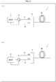
- FIG. 3 is a block diagram of a measurement device 1 in accordance with Embodiment 1.
- the measurement device 1 is a device for measuring an effective refractive index difference ⁇ n eff of a multimode fiber MF, and includes a BOTDR (Brillouin Optical-Fiber Time Domain Reflectometry) 11, a circulator 12, single-mode fibers 13 and 14, and a mode coupler 15.
- the BOTDR 11 includes an output port and an input port.
- the output port of the BOTDR 11 is connected to a first port of the circulator 12, and the input port of the BOTDR 11 is connected to a third port of the circulator 12.
- the BOTDR 11 has (i) a function of outputting pulsed light through the output port and (ii) a function of measuring a Brillouin frequency shift at each point in the multimode fiber MF from a frequency spectrum of scattered light inputted through the input port, that is, a function of measuring distribution of the Brillouin frequency shift in the multimode fiber MF. Note that, for details of the BOTDR 11, Non-Patent Literature 2 should be referred to.
- the circulator 12 includes three ports (that is, the first port, a second port, and the third port).
- light inputted through the first port is outputted through the second port
- light inputted through the second port is outputted through the third port
- light inputted through the third port is outputted through the first port.
- the first port of the circulator 12 is connected to the output port of the BOTDR 11
- the third port of the circulator 12 is connected to the input port of the BOTDR.
- the second port of the circulator 12 is connected to any one of respective entrance ends of the single-mode fibers 13 and 14. It is possible for an operator to freely switch between a connection pattern illustrated in (a) of Fig. 3 and a connection pattern illustrated in (b) of Fig. 3 .
- the single-mode fiber 13 (first single-mode fiber) is connected to the second port of the circulator 12.
- the single-mode fiber 14 (second single-mode fiber) is connected to the second port of the circulator 12.
- the entrance end of the single-mode fiber 13 is connectable to the second port of the circulator 12, and an exit end of the single-mode fiber 13 is connected to a first input port of the mode coupler 15.
- the entrance end of the single-mode fiber 14 is connectable to the second port of the circulator 12, and an exit end of the single-mode fiber 14 is connected to a second input port of the mode coupler 15.
- the mode coupler 15 includes two input ports (that is, the first input port and the second input port) and one output port. As has been described, the first input port of the mode coupler 15 is connected to the exit end of the single-mode fiber 13, and the second input port of the mode coupler 15 is connected to the exit end of the single-mode fiber 14. The output port of the mode coupler 15 is connected to an entrance end of the multimode fiber MF.
- the mode coupler 15 couples a propagation mode in the single-mode fiber 13 with an LP01 mode in the multimode fiber MF, and couples a propagation mode in the single-mode fiber 14 with an LP11 mode in the multimode fiber MF.
- the single-mode fiber 13 By connecting the single-mode fiber 13 to the second port of the circulator 12 as illustrated in (a) of Fig. 3 , it is possible to input, into the multimode fiber MF, pulsed light generated in the BOTDR 11, and possible to input, into the BOTDR 11, merely scattered light in the LP01 mode, out of scattered light having occurred in the multimode fiber MF.
- the BOTDR 11 specifies a Brillouin frequency shift v LP01 ⁇ L01 ⁇ LP01 from a frequency spectrum of the scattered light in the LP01 mode.
- the single-mode fiber 14 to the second port of the circulator 12 as illustrated in (b) of Fig. 3 , it is possible to input, into the multimode fiber MF, pulsed light generated in the BOTDR 11, and possible to input, into the BOTDR 11, merely scattered light in the LP11 mode, out of scattered light having occurred in the multimode fiber MF.
- the BOTDR 11 specifies a Brillouin frequency shift v LP11 ⁇ L01 ⁇ LP11 from a frequency spectrum of the scattered light in the LP11 mode.
- An effective refractive index difference ⁇ n eff between the LP01 mode and the LP11 mode is obtained by calculating 1/(2kV L01 ) of a difference between the Brillouin frequency shift v LP01 ⁇ L01 ⁇ LP01 and the Brillouin frequency shift v LP11 ⁇ L01 ⁇ LP11 with use of a computer embedded in or connected to the BOTDR 11.
- the BOTDR 11 is capable of obtaining a time series of Brillouin frequency shifts from frequency spectra of scattered light inputted at respective time points.
- the scattered light inputted into the BOTDR 11 at the respective time points correspond to scattered light having occurred at respective points in the multimode fiber MF. Therefore, it is possible to consider the time series of the Brillouin frequency shifts, which is obtained by the BOTDR 11, as longitudinal distribution (spatial distribution along a longitudinal axis) of a Brillouin frequency shift in the multimode fiber MF.
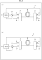
- Fig. 4 is a block diagram of a measurement device 2 in accordance with Embodiment 2.
- the measurement device 2 is a device for measuring an effective refractive index difference ⁇ n eff of a multimode fiber MF, and includes a BOTDA (Brillouin Optical-Fiber Time Domain Analysis) 21, a circulator 22, single-mode fibers 23 through 26, and mode couplers 27 and 28.
- BOTDA BitTorrent Optical-Fiber Time Domain Analysis
- the BOTDA 21 includes a pump light output port, a probe light output port, and a probe light input port.
- the pump light output port of the BOTDA 21 is connected to a first port of the circulator 22, and the probe light input port of the BOTDA 21 is connected to a third port of the circulator 22.
- the probe light output port of the BOTDA 21 is connected to the mode coupler 28 via any one of the single-mode fibers 25 and 26.
- the BOTDA 21 has (i) a function of outputting pulsed light through the pump light output port, (ii) a function of outputting continuous light through the probe light output port, and (iii) a function of measuring a Brillouin frequency shift at each point in the multimode fiber MF from a frequency spectrum of an amplification degree of probe light inputted through the probe light input port, that is, a function of measuring distribution of the Brillouin frequency shift in the multimode fiber MF.
- Non-Patent Literature 3 should be referred to.
- the circulator 22 includes three ports (that is, the first port, a second port, and the third port). In the circulator 22, light inputted through the first port is outputted through the second port, light inputted through the second port is outputted through the third port, and light inputted through the third port is outputted through the first port. As has been described, the first port of the circulator 22 is connected to the pump light output port of the BOTDA 21, and the third port of the circulator 22 is connected to the probe light input port of the BOTDA. The second port of the circulator 22 is connected to any one of respective entrance ends of the single-mode fibers 23 and 24. It is possible for an operator to freely switch between a connection pattern illustrated in (a) of Fig. 4 and a connection pattern illustrated in (b) of Fig.
- the single-mode fiber 23 is connected to the second port of the circulator 22, and the single-mode fiber 25 (third single-mode fiber) is connected to the probe light output port of the BOTDA.
- the single-mode fiber 24 is connected to the second port of the circulator 22, and the single-mode fiber 26 (fourth single-mode fiber) is connected to the probe light output port of the BOTDA.
- the entrance end of the single-mode fiber 23 is connectable to the second port of the circulator 22, and an exit end of the single-mode fiber 23 is connected to a first input port of the mode coupler 27.
- the entrance end of the single-mode fiber 24 is connectable to the second port of the circulator 22, and an exit end of the single-mode fiber 24 is connected to a second input port of the mode coupler 27.
- An entrance end of the single-mode fiber 25 is connectable to the probe light output port of the BOTDA 21, and an exit end of the single-mode fiber 25 is connected to a first input port of the mode coupler 28.
- An entrance end of the single-mode fiber 26 is connectable to the probe light output port of the BOTDA 21, and an exit end of the single-mode fiber 26 is connected to a second input port of the mode coupler 28.
- the mode coupler 27 includes two input ports (that is, the first input port and the second input port) and one output port. As has been described, the first input port of the mode coupler 27 is connected to the exit end of the single-mode fiber 23, and the second input port of the mode coupler 27 is connected to the exit end of the single-mode fiber 24. The output port of the mode coupler 27 is connected to an entrance end of the multimode fiber MF.
- the mode coupler 27 couples a propagation mode in the single-mode fiber 23 with an LP01 mode in the multimode fiber MF, and couples a propagation mode in the single-mode fiber 24 with an LP11 mode in the multimode fiber MF.
- the mode coupler 28 includes two input ports (that is, the first input port and the second input port) and one output port. As has been described, the first input port of the mode coupler 28 is connected to the exit end of the single-mode fiber 25, and the second input port of the mode coupler 28 is connected to the exit end of the single-mode fiber 26. The output port of the mode coupler 28 is connected to an entrance end of the multimode fiber MF which entrance end is opposite from the mode coupler 27.
- the mode coupler 28 couples a propagation mode in the single-mode fiber 25 with the LP01 mode in the multimode fiber MF, and couples a propagation mode in the single-mode fiber 26 with the LP11 mode in the multimode fiber MF.
- the single-mode fiber 23 By connecting the single-mode fiber 23 to the second port of the circulator 22 and connecting the single-mode fiber 25 to the probe light output port of the BOTDA 21 as illustrated in (a) of Fig. 4 , it is possible to input, into the multimode fiber MF, pulsed light generated in the BOTDA 21, and possible to input, into the BOTDA 21, probe light in the LP01 mode which probe light has been amplified in the multimode fiber MF.
- the BOTDA 21 specifies a Brillouin frequency shift v LP01 ⁇ L01 ⁇ LP01 from a frequency spectrum of an amplification degree of the probe light in the LP01 mode.
- the single-mode fiber 24 By connecting the single-mode fiber 24 to the second port of the circulator 22 and connecting the single-mode fiber 26 to the probe light output port of the BOTDA 21 as illustrated in (b) of Fig. 4 , it is possible to input, into the multimode fiber MF, pulsed light generated in the BOTDA 21, and possible to input, into the BOTDA 21, probe light in the LP11 mode which probe light has been amplified in the multimode fiber MF.
- the BOTDA 21 specifies a Brillouin frequency shift v LP11 ⁇ L01 ⁇ LP11 from a frequency spectrum of an amplification degree of the probe light in the LP11 mode.
- An effective refractive index difference ⁇ n eff between the LP01 mode and the LP11 mode is obtained by calculating 1/(2kV L01 ) of a difference between the Brillouin frequency shift v LP01 ⁇ L01 ⁇ LP01 and the Brillouin frequency shift v LP11 ⁇ L01 ⁇ LP11 with use of a computer embedded in or connected to the BOTDA 21.
- the BOTDA 21 is capable of obtaining a time series of Brillouin frequency shifts from frequency spectra of scattered light inputted at respective time points.
- the scattered light inputted into the BOTDA 21 at the respective time points correspond to scattered light having occurred at respective points in the multimode fiber MF. Therefore, it is possible to consider the time series of the Brillouin frequency shifts, which is obtained by the BOTDA 21, as longitudinal distribution of a Brillouin frequency shift in the multimode fiber MF. Furthermore, it is possible to consider a time series of effective refractive index differences ⁇ n eff , which is obtained from the time series of the Brillouin frequency shifts, as longitudinal distribution of an effective refractive index difference ⁇ n eff in the multimode fiber MF.
- FIG. 5 is a flowchart of the measurement method S. Note that, although a method of measuring an effective refractive index difference ⁇ n eff with use of a measurement device 1 including a BOTDR 11 will be described below, the present invention is not limited to such a method. That is, it is possible to measure the effective refractive index difference ⁇ n eff with use of, for example, a measurement device 2 including a BOTDA 21.
- the measurement method S is a method for measuring an effective refractive index difference ⁇ n eff of a multimode fiber MF with use of a measurement device 1, and includes a fiber connecting step S11, a Brillouin frequency shift v LP01 ⁇ L01 ⁇ LP01 measuring step S12, a fiber switching step S13, a Brillouin frequency shift v LP11 ⁇ L01 ⁇ LP11 measuring step S14, and an effective refractive index difference ⁇ n eff calculating step S15.
- the fiber connecting step S11 is a step of connecting a single-mode fiber 13 to a second port of a circulator 12.
- the Brillouin frequency shift v LP01 ⁇ L01 ⁇ LP01 measuring step S12 is a step of measuring a Brillouin frequency shift v LP01 ⁇ L01 ⁇ LP01 with use of a BOTDR 11. Specifically, with use of the BOTDR 11, (1) pulsed light is inputted into a multimode fiber MF, (2) a frequency spectrum of scattered light in an LP01 mode is measured, and (3) a frequency is specified which gives the lowest-frequency peak out of peaks in the frequency spectrum thus measured. As has been described in the section [measurement principle], the frequency thus specified represents the Brillouin frequency shift v LP01 ⁇ L01 ⁇ LP01 .
- step S12 it is possible to achieve a process of specifying a frequency/frequencies which gives/give a peak/peaks in the frequency spectrum of the scattered light in the LP01 mode, by software with use of a program which causes a computer (not illustrated), embedded in or connected to the BOTDR 11, to carry out a given procedure and which is stored in a storage device included in the computer. Note that, since a procedure for specifying the frequency/frequencies which gives/give the peak/peaks in the frequency spectrum is publicly known, the procedure will not be described here.
- the fiber switching step S13 is a step of switching a single-mode fiber connected to the circulator 12 from the single-mode fiber 13 to a single-mode fiber 14.
- the Brillouin frequency shift v LP11 ⁇ L01 ⁇ LP11 measuring step S14 is a step of measuring a Brillouin frequency shift v LP11 ⁇ L01 ⁇ LP11 with use of the BOTDR 11. Specifically, with use of the BOTDR 11, (1) pulsed light is inputted into the multimode fiber MF, (2) a frequency spectrum of scattered light in an LP11 mode is measured, and (3) a frequency is specified which gives the lowest-frequency peak out of peaks in the frequency spectrum thus measured. As has been described in the section [measurement principle], the frequency thus specified represents the Brillouin frequency shift v LP11 ⁇ L01 ⁇ LP11 .
- step S14 it is possible to achieve a process of specifying the frequency which gives the lowest-frequency peak out of two peaks in the frequency spectrum of the scattered light in the LP11 mode, by software with use of a program which causes the computer to carry out a given procedure and which is stored in the storage device.
- a procedure for specifying frequencies which give the respective two peaks fitting (v LP11 ⁇ L01 ⁇ LP11 and v LP11 ⁇ L21 ⁇ LP11 are determined so that f(v) defined by Expression (10) best approximates a measured spectrum) can be used.
- f(v) defined by Expression (10) best approximates a measured spectrum
- the effective refractive index difference ⁇ n eff calculating step S15 is a step of calculating an effective refractive index difference ⁇ n eff between the LP01 mode and the LP11 mode in accordance with Expression (11) with use of the Brillouin frequency shift v LP01 ⁇ L01 ⁇ LP01 measured in the step S12 and the Brillouin frequency shift v LP11 ⁇ L01 ⁇ LP11 measured in the step S14.
- a procedure for calculating the effective refractive index difference ⁇ n eff examples include a procedure in which (1) the Brillouin frequency shift v LP11 ⁇ L01 ⁇ LP11 is subtracted from the Brillouin frequency shift v LP01 ⁇ L01 ⁇ LP01 , (2) a difference thus obtained is divided by 2, (3) a quotient thus obtained is further divided by a constant k, and (4) a quotient thus obtained is further divided by a constant V L01 .
- the step S12 (S14) can be a step of measuring a Brillouin frequency shift v LP01 ⁇ L01 ⁇ LP01 (v LP11 ⁇ L01 ⁇ LP11 ) at a specific point in the multimode fiber MF or can be alternatively a step of measuring longitudinal distribution of a Brillouin frequency shift v LP01 ⁇ L01 ⁇ LP01 (v LP11 ⁇ L01 ⁇ LP11 ) in the multimode fiber MF.
- the step S15 can be a step of calculating an effective refractive index difference ⁇ n eff at the specific point in the multimode fiber MF from the Brillouin frequency shift v LP01 ⁇ L01 ⁇ LP01 (v LP11 ⁇ L01 ⁇ LP11 ) at the specific point in the multimode fiber MF or can be alternatively a step of calculating longitudinal distribution of an effective refractive index difference ⁇ n eff in the multimode fiber MF from the longitudinal distribution of the Brillouin frequency shift v LP01 ⁇ L01 ⁇ LP01 (v LP11 ⁇ L01 ⁇ LP11 ) in the multimode fiber MF.
- FIG. 6 illustrates a frequency spectrum of scattered light in an LP01 mode, which frequency spectrum was actually measured in the step S12.
- (b) of Fig. 6 illustrates a frequency spectrum of scattered light in an LP11 mode, which frequency spectrum was actually measured in the step S14.
- scattered light measured in the step S14 is scattered light which has occurred by a scattering process ⁇ LP11 ⁇ L01 ⁇ LP11> or ⁇ LP11 ⁇ L21 ⁇ LP11> or which has occurred via a higher acoustic mode. Therefore, it is possible to specify scattering intensities, which correspond to respective scattering processes, and Brillouin frequency shifts, which correspond to the respective scattering processes, as A1, v1, A2, v2, A3, and v3 which give the best approximation of an actually measured frequency spectrum to a sum f(v) of three Lorentzian functions, which sum is defined by Expression (13).
- an effective refractive index difference ⁇ n eff calculated in the step S15 is 5.9 ⁇ 10 -3 . This result shows that the effective refractive index difference well corresponds to a design value.
- the present invention is not limited to the embodiments, but can be altered by a skilled person in the art within the scope of the claims.
- the present invention also encompasses, in its technical scope, any embodiment derived by combining technical means disclosed in differing embodiments. Further, it is possible to form a new technical feature by combining the technical means disclosed in the respective embodiments.
- a multimode fiber having merely an LP01 mode and an LP11 mode as propagation modes
- an effective refractive index difference between the LP01 mode and the LP11 mode is measured.
- the present invention is not limited to such an embodiment. That is, according to an embodiment of the present invention, it is possible to measure an effective refractive index difference between two propagation modes (one of which is referred to as a first propagation mode and the other of which is referred to as a second propagation mode) which are arbitrarily selected from propagation modes that a multimode fiber has.
- Some mode couplers couple degenerate propagation modes (for example, LP11a mode and LP11b mode) in a multimode fiber with a propagation mode in a single single-mode fiber without any distinction, and others couple the degenerate propagation modes in the multimode fiber to respective propagation modes in a plurality of single-mode fibers in distinction.
- a mode coupler of a latter type any of the plurality of single-mode fibers can be used.
- the measurement method in accordance with an embodiment is preferably arranged such that: the step (a) is a step of measuring longitudinal distribution of the first Brillouin frequency shift v1 in the multimode fiber with use of a BOTDR(Brillouin Optical-Fiber Time Domain Reflectometry) or a BOTDA(Brillouin Optical-Fiber Time Domain Analysis); the step (b) is a step of measuring longitudinal distribution of the second Brillouin frequency shift v2 in the multimode fiber with use of the BOTDR; and the step (c) is a step of calculating longitudinal distribution of the effective refractive index difference ⁇ n eff in the multimode fiber with use of the longitudinal distribution of the first Brillouin frequency shift v1 measured in the step (a) and the longitudinal distribution of the second Brillouin frequency shift v2 measured in the step (b).
- the measurement method in accordance with an embodiment is preferably arranged such that: in the step (a), a frequency is specified which gives a peak of a single Lorentzian function that best approximates the frequency spectrum or which gives the lowest-frequency peak out of respective peaks of a plurality of Lorentzian functions a sum of which best approximates the frequency spectrum; and in the step (b), a frequency is specified which gives a peak of a single Lorentzian function that best approximates the frequency spectrum or which gives the lowest-frequency peak out of respective peaks of a plurality of Lorentzian functions a sum of which best approximates the frequency spectrum.
- the first Brillouin frequency shift v1 even in a case where the frequency spectrum which is referred to in the step (a) includes peaks, corresponding to respective scattering processes, in such a manner that the peaks overlap each other and are not apparently identifiable.
- the second Brillouin frequency shift v2 even in a case where the frequency spectrum which is referred to in the step (b) includes peaks, corresponding to respective scattering processes, in such a manner that the peaks overlap each other and are not apparently identifiable.
- the measurement method in accordance with an embodiment is preferably arranged such that: the first propagation mode is an LP01 mode; the second propagation mode is an LP11 mode; the first Brillouin frequency shift v1 is a Brillouin frequency shift v LP01 ⁇ L01 ⁇ LP01 corresponding to a scattering process in which scattered light in the LP01 mode occurs from light in the LP01 mode via an acoustic mode L01; the second Brillouin frequency shift v2 is a Brillouin frequency shift v LP11 ⁇ L01 ⁇ LP11 corresponding to a scattering process in which scattered light in the LP11 mode occurs from light in the LP11 mode via the acoustic mode L01; and the constant V L is an approximate value of a longitudinal phase velocity V L01 of the acoustic mode L01.
- a measurement device in accordance with Embodiment 1 is a measurement device for measuring an effective refractive index difference between two propagation modes which a multimode fiber has, the device including: a BOTDR having an output port and an input port; a circulator having a first port, a second port, and a third port, the first port of the circulator being connected to the output port of the BOTDR, the third port of the circulator being connected to the input port of the BOTDR; first and second single-mode fibers each having an input end and an output end, any one of the input end of the first single-mode fiber and the input end of the second single-mode fiber being switchably connected to the second port of the circulator; and a mode coupler having a first input port, a second input port, and an output port, the first input port of the mode coupler being connected to the output end of the first single-mode fiber, the second input port of the mode coupler being connected to the output end of the second single-mode fiber, the output port of the mode coupler being connected to an input
- a measurement device in accordance with Embodiment 2 is a measurement device for measuring an effective refractive index difference between two propagation modes which a multimode fiber has, the device including: a BOTDA having a pump light output port and a probe light input port; a circulator having a first port, a second port, and a third port, the first port of the circulator being connected to the pump light output port of the BOTDA, the third port of the circulator being connected to the probe light input port of the BOTDA; first and second single-mode fibers each having an input end and an output end, any one of the input end of the first single-mode fiber and the input end of the second single-mode fiber being switchably connected to the second port of the circulator; a first mode coupler having a first input port, a second input port, and an output port, the first input port of the first mode coupler being connected to the output end of the first single-mode fiber, the second input port of the first mode coupler being connected to the output end of the second single-mode fiber, the
Landscapes
- Physics & Mathematics (AREA)
- General Physics & Mathematics (AREA)
- Optics & Photonics (AREA)
- Chemical & Material Sciences (AREA)
- Analytical Chemistry (AREA)
- Engineering & Computer Science (AREA)
- Microelectronics & Electronic Packaging (AREA)
- Testing Of Optical Devices Or Fibers (AREA)
- Optical Transform (AREA)
Abstract
Description
- The present invention relates to a measurement method, a measurement device, and a measurement program, each of which is for measuring an effective refractive index difference between propagation modes which a multimode fiber has.
- In recent years, multimode fibers having a plurality of propagation modes have been actively developed. According to a transmission system employing a multimode fiber as a transmission medium, an effective refractive index difference between propagation modes which the multimode fiber has is an important design parameter. Therefore, a measurement method for measuring an effective refractive index difference between propagation modes in a multimode fiber has been demanded.
- Non-Patent
Literature 1 discloses that an effective refractive index difference between propagation modes in a multimode fiber can be measured by the following method. That is, by applying periodic external force to the multimode fiber, a refractive index grating is formed in which a refractive index varies in a light propagation direction. Then, while a grating period of the refractive index grating is varied, strength of coupling between respective powers of the propagation modes is measured. It is known that, in so doing, a reciprocal of the grating period which causes the strength of the coupling between the respective powers of the propagation modes to be maximized matches a propagation constant difference between the propagation modes. Therefore, by measuring the grating period which causes the strength of the coupling between the respective powers of the propagation modes to be maximized, it is possible to calculate the effective refractive index difference between the propagation modes from the grating period thus measured. -
- [Non-Patent Literature 1] Christian Schulze, Johannes Wilde, Robert Bruning, Siegmund Schroter, and Michael Duparre, Measurement of effective refractive index differences in multimode optical fibers based on modal decomposition, OPTICS LETTERS, Vol. 39, No. 20, October 15, 2014
- [Non-Patent Literature 2] Toshio Kurashima et al., Brillouin Optical-Fiber Time Domain Reflectometry, IEICE Transaction on Comminications, Vol. E76, No. 4, pp. 382-390, 1993
- [Non-Patent Literature 3] T. Horiguchi and M. Tateda, BOTDA-Nondestructive Measurement of Single-Mode Optical Fiber Attenuation Characteristics Using Brillouin Interaction: Theory, J. Lightwave technol., Vol. 7, No. 8, pp. 1170-1176, 1989
- However, according to a measurement method disclosed in
Non-Patent Literature 1, it is not possible to measure an effective refractive index difference between propagation modes at a specific point in a multimode fiber. Namely, according to the measurement method disclosed inNon-Patent Literature 1, it is not possible to measure the effective refractive index difference between the propagation modes at each point in the multimode fiber, that is, it is not possible to measure spatial distribution, in a longitudinal direction, of the effective refractive index difference between the propagation modes in the multimode fiber (hereinafter, referred to as "longitudinal distribution"). - The present invention has been made in view of the above problem, and an object of the present invention is to realize a measurement method, a measurement device, and a measurement program, each of which allows measurement of an effective refractive index difference between propagation modes at a specific point in a multimode fiber.
- In order to attain the above object, a measurement method in accordance with an aspect of the present invention is a measurement method for measuring an effective refractive index difference between two propagation modes which a multimode fiber has, the method including the steps of: (a) measuring a first Brillouin frequency shift v1 by specifying a frequency which gives the lowest-frequency peak out of peaks included in a frequency spectrum of scattered light in a first propagation mode which scattered light occurs in a case where light in the first propagation mode is inputted into the multimode fiber; (b) measuring a second Brillouin frequency shift v2 by specifying a frequency which gives the lowest-frequency peak out of peaks included in a frequency spectrum of scattered light in a second propagation mode which scattered light occurs in a case where light in the second propagation mode is inputted into the multimode fiber; and (c) calculating an effective refractive index difference Δneff in accordance with Δneff = (v1-v2)/(2kVL) with use of (i) the first Brillouin frequency shift v1 measured in the step (a), (ii) the second Brillouin frequency shift v2 measured in the step (b), (iii) a predetermined wave number k of light in a vacuum, and (iv) a predetermined constant VL.
- In order to attain the above object, a measurement device in accordance with an aspect of the present invention is a measurement device for measuring an effective refractive index difference between two propagation modes which a multimode fiber has, the device including: a BOTDR having an output port and an input port; a circulator having a first port, a second port, and a third port, the first port of the circulator being connected to the output port of the BOTDR, the third port of the circulator being connected to the input port of the BOTDR; first and second single-mode fibers each having an input end and an output end, any one of the input end of the first single-mode fiber and the input end of the second single-mode fiber being switchably connected to the second port of the circulator; and a mode coupler having a first input port, a second input port, and an output port, the first input port of the mode coupler being connected to the output end of the first single-mode fiber, the second input port of the mode coupler being connected to the output end of the second single-mode fiber, the output port of the mode coupler being connected to an input end of the multimode fiber, the mode coupler being configured to couple a propagation mode in the first single-mode fiber with a first propagation mode in the multimode fiber and couple a propagation mode in the second single-mode fiber with a second propagation mode in the multimode fiber.
- Alternatively, in order to attain the above object, a measurement device in accordance with an aspect of the present invention is a measurement device for measuring an effective refractive index difference between two propagation modes which a multimode fiber has, the device including: a BOTDA having a pump light output port and a probe light input port; a circulator having a first port, a second port, and a third port, the first port of the circulator being connected to the pump light output port of the BOTDA, the third port of the circulator being connected to the probe light input port of the BOTDA; first and second single-mode fibers each having an input end and an output end, any one of the input end of the first single-mode fiber and the input end of the second single-mode fiber being switchably connected to the second port of the circulator; a first mode coupler having a first input port, a second input port, and an output port, the first input port of the first mode coupler being connected to the output end of the first single-mode fiber, the second input port of the first mode coupler being connected to the output end of the second single-mode fiber, the output port of the first mode coupler being connected to an input end of the multimode fiber, the first mode coupler being configured to couple a propagation mode in the first single-mode fiber with a first propagation mode in the multimode fiber and couple a propagation mode in the second single-mode fiber with a second propagation mode in the multimode fiber; third and fourth single-mode fibers each having an input end and an output end, any one of the output end of the third single-mode fiber and the output end of the fourth single-mode fiber being switchably connected to the probe light input port of the BOTDA; and a second mode coupler having an input port, a first output port, and a second output port, the input port of the second mode coupler being connected to an output end of the multimode fiber, the first output port of the second mode coupler being connected to the input end of the third single-mode fiber, the second output port of the second mode coupler being connected to the input end of the fourth single-mode fiber, the second mode coupler being configured to couple the first propagation mode in the multimode fiber with a propagation mode in the third single-mode fiber and couple the second propagation mode in the multimode fiber with a propagation mode in the second single-mode fiber.
- In order to attain the above object, a measurement program in accordance with an aspect of the present invention is a measurement program for measuring an effective refractive index difference between two propagation modes which a multimode fiber has, the program causing a computer to carry out procedures for: (a) measuring a first Brillouin frequency shift v1 by specifying a frequency which gives the lowest-frequency peak out of peaks included in a frequency spectrum of scattered light in a first propagation mode which scattered light occurs in a case where light in the first propagation mode is inputted into the multimode fiber; (b) measuring a second Brillouin frequency shift v2 by specifying a frequency which gives the lowest-frequency peak out of peaks included in a frequency spectrum of scattered light in a second propagation mode which scattered light occurs in a case where light in the second propagation mode is inputted into the multimode fiber; and (c) calculating an effective refractive index difference Δneff in accordance with Δneff = (v1-v2)/(2kVL) with use of (i) the first Brillouin frequency shift v1 measured in the step (a), (ii) the second Brillouin frequency shift v2 measured in the step (b), (iii) a predetermined wave number k of light in a vacuum, and (iv) a predetermined constant VL.
- According to an aspect of the present invention, it is possible to measure an effective refractive index difference between propagation modes at a specific point in a multimode fiber. Furthermore, according to an aspect of the present invention, it is possible to measure distribution of the effective refractive index difference between the propagation modes in the multimode fiber.
-
- (a) of
Fig. 1 is a diagram illustrating a scattering process of Brillouin scattering which can occur in a multimode fiber in a case where light in an LP01 mode is inputted. (b) ofFig. 1 is a diagram illustrating a scattering process of Brillouin scattering which can occur in a multimode fiber in a case where light in an LP11 mode is inputted. - (a) of
Fig. 2 is a graph illustrating a frequency spectrum of scattered light in an LP01 mode which scattered light occurs in a multimode fiber in a case where light in an LP01 mode is inputted. (b) ofFig. 2 is a graph illustrating a frequency spectrum of scattered light in an LP11 mode which scattered light occurs in a multimode fiber in a case where light in an LP11 mode is inputted. -
Fig. 3 is a block diagram illustrating a measurement device in accordance withEmbodiment 1 of the present invention. (a) ofFig. 3 illustrates a state where a first single-mode fiber for measurement of an LP01 mode is connected to a BOTDR via a circulator. (b) ofFig. 3 illustrates a state where a second single-mode fiber for measurement of an LP11 mode is connected to the BOTDR via the circulator. -
Fig. 4 is a block diagram illustrating a measurement device in accordance withEmbodiment 2 of the present invention. (a) ofFig. 4 illustrates a state where a first single-mode fiber for measurement of an LP01 mode is connected to a BOTDA via a circulator. (b) ofFig. 4 illustrates a state where a second single-mode fiber for measurement of an LP11 mode is connected to the BOTDA via the circulator. -
Fig. 5 is a flowchart illustrating a measurement method in accordance with an embodiment of the present invention. - (a) of
Fig. 6 is a graph illustrating a specific example of a frequency spectrum measured in a step S12 illustrated inFig. 5 . (b) ofFig. 6 is a graph illustrating a specific example of a frequency spectrum measured in a step S14 illustrated inFig. 5 . &(c) ofFig. 6 is a graph obtained by individually plotting three Lorentzian functions, a sum of which best approximates the frequency spectrum measured in the step S14 illustrated inFig. 5 . - The present invention mainly relates to a measurement method for measuring an effective refractive index difference of a multimode fiber on the basis of scattered light which occurs due to Brillouin scattering. Here, before embodiments of the present invention are described, a measurement principle will be described below on which the embodiments of the present invention are based. Note that the measurement principle described below is a novel measurement principle which the inventors of the present application have devised by themselves and which is disclosed for the first time in this specification.
- Brillouin scattering is a phenomenon in which inputted light is scattered backward due to an acoustic mode which thermally occurs. A frequency of light which occurs due to the Brillouin scattering (hereinafter, referred to as "scattered light") in an optical fiber is lower, by approximately 11 GHz, than that of inputted light. A difference between the frequency of the inputted light and the frequency of the scattered light is referred to as a Brillouin frequency shift.
- As well known, the following two conditions need to be satisfied so that Brillouin scattering occurs in an optical fiber.
- A first condition is a Bragg condition. That is, Expression (1) is established between an effective refractive index ni for inputted light and an effective refractive index nj for scattered light. In Expression (1), K1 represents a propagation constant, in a propagation axis direction, of an acoustic mode which is involved in the Brillouin scattering (1 represents a mode number of the acoustic mode), and k represents a wave number of light in a vacuum.
[Math. 1]
- A second condition is that an overlap integral γij1 defined by Expression (2) is not zero. In Expression (2), x and y each represents a coordinate in a cross-sectional direction of the optical fiber, ϕi(x, y) represents a field profile of the inputted light, and ϕj(x, y) represents a field profile of the scattered light. Ψ1 represents a profile of a change in refractive index which change is caused due to the acoustic mode which is involved in the Brillouin scattering, and * represents phase conjugation.
[Math. 2]
- Note that an acoustic mode which is involved in Brillouin scattering in an optical fiber is a longitudinal vibration mode which has displacement in a propagation axis direction of the optical fiber. A profile of a change in refractive index which change is caused due to each acoustic mode is similar to a field profile of any propagation mode in the optical fiber. In the description below, an acoustic mode which causes a profile of a change in refractive index to be similar to a field profile of an LPmn mode will be represented by Lmn.
- A multimode fiber (two-mode fiber) having merely an LP01 mode and an LP11 mode as propagation modes will be taken as an example, and modes of scattered light which can occur will be studied for each of modes of inputted light.
- In the description below, a scattering process in which scattered light in an LPj1 mode occurs from inputted light in an LPi1 mode via an acoustic mode Lmn will be represented by <LPi1 → Lmn → LPj1> (i, j = 0 or 1). For example, <LP01 → L01 → LP01> represents a process in which scattered light in the LP01 mode occurs from inputted light in the LP01 mode via an acoustic mode L01, and <LP11 → L01 → LP11> represents a process in which scattered light in the LP11 mode occurs from inputted light in the LP11 mode via the acoustic mode L01.
- In a case where a mode of inputted light is the LP01 mode, there can be a scattering process <LP01 → Lmn → LP01>, in which a mode of scattered light is the LP01 mode, and a scattering process <LP01 → Lmn → LP11>, in which a mode of scattered light is the LP11 mode. Out of such scattering processes, the following two scattering processes each result in that an overlap integral defined by Expression (2) is not zero. The other scattering processes each result in that an overlap integral defined by Expression (2) is zero due to symmetry of modes.
- <LP01 → L01 → LP01>
<LP01 → L11 → LP11> - That is, in a case where a mode of inputted light is the LP01 mode, the following scattered light occurs as illustrated in (a) of
Fig. 1 : (1) scattered light in the LP01 mode, which scattered light has been scattered via the acoustic mode L01; and (2) scattered light in the LP11 mode, which scattered light has been scattered via an acoustic mode L11. - In a case where a mode of inputted light is the LP11 mode, the following three scattering processes each result in that an overlap integral defined by Expression (2) is not zero, out of possible scattering processes <LP11 → Lmn → LP01> and <LP11 → Lmn → LP11>. The other scattering processes each result in that an overlap integral defined by Expression (2) is zero due to symmetry of modes.
- <LP11 → L01 → LP11>
<LP11 → L21 → LP11>
<LP11 → L11 → LP01> - Therefore, in a case where a mode of inputted light is the LP11 mode, the following scattered light occurs as illustrated in (b) of
Fig. 1 : (1) scattered light in the LP11 mode, which scattered light has been scattered via the acoustic mode L01; (2) scattered light in the LP11 mode, which scattered light has been scattered via an acoustic mode L21; and (3) scattered light in the LP01 mode, which scattered light has been scattered via the acoustic mode L11. - As has been described, in a case where a mode of inputted light is the LP01 mode, the following scattered light occurs: (1) scattered light in the LP01 mode, which scattered light has been scattered via the acoustic mode L01; and (2) scattered light in the LP11 mode, which scattered light has been scattered via the acoustic mode L11. Therefore, by selecting the LP01 mode as an observation target, it is possible to selectively observe scattered light which has been scattered via the acoustic mode L01.
- Studied below will be a scattering process <LP01 → L01 → LP01> of Brillouin scattering which occurs via the acoustic mode L01, in a case where a mode of inputted light and a mode of scattered light, which is an observation target, are each the LP01 mode.
- As a Bragg condition for the scattering process <LP01 → L01 → LP01>, an effective refractive index nLP01 for the LP01 mode and a propagation constant KL01 of the acoustic mode L01 have a relationship therebetween defined by Expression (3).
[Math. 3]
- A Brillouin frequency shift vLP01 → L01 → LP01 in the scattering process <LP01 → L01 → LP01> is given by Expression (4). Note that, in Expression (4), VL01 represents a longitudinal phase velocity of the acoustic mode L01 (also referred to as a "lengthwise phase velocity" or an "axial phase velocity").
[Math. 4]
- An observed frequency spectrum f(v) of the scattered light is a Lorentzian function having a peak at v = vLP01 → L01 → LP01 as shown by Expression (5). (a) of
Fig. 2 shows a graph of this frequency spectrum f(v). Note that, in Expression (5), Δv represents a constant (Δv = 1/(π·τc)) determined depending on a lifetime τc of an acoustic mode (which lifetime τc is constant regardless of the mode), and represents a width (full width at half maximum) of a peak in a frequency spectrum f(v).
[Math. 5]
- Therefore, in a case where a mode of inputted light and a mode of scattered light, which is an observation target, are each the LP01 mode, it is possible to specify a Brillouin frequency shift vLP01 → L01 → LP01 by specifying a frequency which gives a peak in an observed frequency spectrum f(v) of the scattered light.
- Note that, in a case where acoustic modes which are higher than an L21 mode are involved in Brillouin scattering, an observed frequency spectrum f(v) of scattered light can include further peaks. Note, however, that such peaks are formed at respective frequencies which are higher than a Brillouin frequency shift vLP01 → L01 → LP01 to be specified. Therefore, even in this case, it is possible to absolutely specify the Brillouin frequency shift vLP01 → L01 → LP01 by specifying a frequency which gives the lowest-frequency peak, out of peaks in the observed frequency spectrum f(v) of the scattered light.
- As has been described, in a case where a mode of inputted light is the LP11 mode, the following scattered light occurs: (1) scattered light in the LP11 mode, which scattered light has been scattered via the acoustic mode L01; (2) scattered light in the LP11 mode, which scattered light has been scattered via the acoustic mode L21; and (3) scattered light in the LP01 mode, which scattered light has been scattered via the acoustic mode L11. Therefore, by selecting the LP11 mode as an observation target, it is possible to selectively observe (i) scattered light which has been scattered via the acoustic mode L01 and (ii) scattered light which has been scattered via the acoustic mode L21.
- Studied below will be (i) a scattering process <LP11 → L01 → LP11> of Brillouin scattering which occurs via the acoustic mode L01 and (ii) a scattering process <LP11 → L21 → LP11> of Brillouin scattering which occurs via the acoustic mode L21, in a case where a mode of inputted light and a mode of scattered light, which is an observation target, are each the LP11 mode.
- As a Bragg condition for the scattering process <LP11 → L01 → LP11>, an effective refractive index nLP11 for the LP11 mode and a propagation constant KL01 of the acoustic mode L01 have a relationship therebetween defined by Expression (6). As a Bragg condition for the scattering process <LP11 → L21 → LP11>, the effective refractive index nLP11 for the LP11 mode and a propagation constant KL21 of the acoustic mode L21 have a relationship therebetween defined by Expression (7).
[Math. 6]
[Math. 7]
- A Brillouin frequency shift vLP11 → L01 → LP11 in the scattering process <LP11 → L01 → LP11> is given by Expression (8). A Brillouin frequency shift vLP11 → L21 → LP11 in the scattering process <LP11 → L21 → LP11> is given by Expression (9). Note that, in Expression (8), VL01 represents a longitudinal phase velocity of the acoustic mode L01, as has been described, and, in Expression (9), VL21 represents a longitudinal phase velocity of the acoustic mode L21.
[Math. 8]
[Math. 9]
- An observed frequency spectrum f(v) of the scattered light is superposition of (i) a Lorentzian function having a peak at v = vLP11 → L01 → LP11 and (ii) a Lorentzian function having a peak at v = vLP11 → L21 → LP11, as shown by Expression (10). (b) of
Fig. 2 shows a graph of this frequency spectrum f(v). Note that, in Expression (10), as has been described, Δv represents a constant determined depending on a lifetime of each acoustic mode, and represents a width of each peak in a frequency spectrum f(v).
[Math. 10]
- Therefore, in a case where a mode of inputted light and a mode of scattered light, which is an observation target, are each the LP11 mode, it is possible to specify a Brillouin frequency shift vLP11 → L01 → LP11 and a Brillouin frequency shift vLP11 → L21 → LP11 by specifying frequencies which give respective two peaks in an observed frequency spectrum f(v) of the scattered light.
- Note that a frequency which gives a lower-frequency peak, out of the two peaks in the frequency spectrum f(v) of the scattered light, is vLP11 → L01 → LP11, and a frequency which gives a higher-frequency peak, out of the two peaks in the frequency spectrum f(v) of the scattered light, is vLP11 → L21 → LP11. This is because, as a mode becomes higher, an effective refractive index becomes lower, that is, VL01 < VL02 is established. Therefore, it is possible to specify the Brillouin frequency shift vLP11 → L01 → LP11 by specifying the frequency which gives the lower-frequency peak, out of the two peaks in the observed frequency spectrum f(v) of the scattered light.
- In a case where acoustic modes which are higher than the L21 mode are involved in Brillouin scattering, an observed frequency spectrum f(v) of scattered light can include further peaks. Note, however, that such peaks are formed at respective frequencies which are higher than a Brillouin frequency shift vLP11 → L01 → LP11 to be specified. Therefore, even in this case, it is possible to absolutely specify the Brillouin frequency shift vLP11 → L01 → LP11 by specifying a frequency which gives the lowest-frequency peak, out of peaks in the observed frequency spectrum f(v) of the scattered light.
- An effective refractive index difference Δneff = nLP01-nLP11 between the LP01 mode and the LP11 mode is given by Expression (11) based on Expressions (4) and (8).
[Math. 11]
- Therefore, by measuring a Brillouin frequency shift vLP01 → L01 → LP01 and a Brillouin frequency shift vLP11 → L01 → LP11, it is possible to calculate the effective refractive index difference Δneff between the LP01 mode and the LP11 mode in accordance with Expression (11) with use of the Brillouin frequency shift vLP01 → L01 → LP01 and the Brillouin frequency shift VLP11 → L01 → LP11.
- Note that a longitudinal phase velocity VL01 of the LP01 mode shown in Expression (11) can be approximated by a longitudinal phase velocity of fused quartz, that is, 5977 m/s. Therefore, by setting VL01 to 5977 m/s, an accurate effective refractive index difference Δneff is obtained by Expression (11). In a case where concentrations of various impurities contained in a multimode fiber are known, a more accurate effective refractive index difference Δneff is obtained by correcting a value of VL01 depending on the concentrations of the various impurities.
-
Embodiment 1 of a measurement device of the present invention will be described below with reference toFig. 3. Fig. 3 is a block diagram of ameasurement device 1 in accordance withEmbodiment 1. - The
measurement device 1 is a device for measuring an effective refractive index difference Δneff of a multimode fiber MF, and includes a BOTDR (Brillouin Optical-Fiber Time Domain Reflectometry) 11, acirculator 12, single-mode fibers mode coupler 15. - The
BOTDR 11 includes an output port and an input port. The output port of theBOTDR 11 is connected to a first port of thecirculator 12, and the input port of theBOTDR 11 is connected to a third port of thecirculator 12. TheBOTDR 11 has (i) a function of outputting pulsed light through the output port and (ii) a function of measuring a Brillouin frequency shift at each point in the multimode fiber MF from a frequency spectrum of scattered light inputted through the input port, that is, a function of measuring distribution of the Brillouin frequency shift in the multimode fiber MF. Note that, for details of theBOTDR 11,Non-Patent Literature 2 should be referred to. - The
circulator 12 includes three ports (that is, the first port, a second port, and the third port). In thecirculator 12, light inputted through the first port is outputted through the second port, light inputted through the second port is outputted through the third port, and light inputted through the third port is outputted through the first port. As has been described, the first port of thecirculator 12 is connected to the output port of theBOTDR 11, and the third port of thecirculator 12 is connected to the input port of the BOTDR. The second port of thecirculator 12 is connected to any one of respective entrance ends of the single-mode fibers Fig. 3 and a connection pattern illustrated in (b) ofFig. 3 . According to the connection pattern illustrated in (a) ofFig. 3 , the single-mode fiber 13 (first single-mode fiber) is connected to the second port of thecirculator 12. According to the connection pattern illustrated in (b) ofFig. 3 , the single-mode fiber 14 (second single-mode fiber) is connected to the second port of thecirculator 12. - The entrance end of the single-
mode fiber 13 is connectable to the second port of thecirculator 12, and an exit end of the single-mode fiber 13 is connected to a first input port of themode coupler 15. The entrance end of the single-mode fiber 14 is connectable to the second port of thecirculator 12, and an exit end of the single-mode fiber 14 is connected to a second input port of themode coupler 15. - The
mode coupler 15 includes two input ports (that is, the first input port and the second input port) and one output port. As has been described, the first input port of themode coupler 15 is connected to the exit end of the single-mode fiber 13, and the second input port of themode coupler 15 is connected to the exit end of the single-mode fiber 14. The output port of themode coupler 15 is connected to an entrance end of the multimode fiber MF. Themode coupler 15 couples a propagation mode in the single-mode fiber 13 with an LP01 mode in the multimode fiber MF, and couples a propagation mode in the single-mode fiber 14 with an LP11 mode in the multimode fiber MF. - By connecting the single-
mode fiber 13 to the second port of thecirculator 12 as illustrated in (a) ofFig. 3 , it is possible to input, into the multimode fiber MF, pulsed light generated in theBOTDR 11, and possible to input, into theBOTDR 11, merely scattered light in the LP01 mode, out of scattered light having occurred in the multimode fiber MF. TheBOTDR 11 specifies a Brillouin frequency shift vLP01 → L01 → LP01 from a frequency spectrum of the scattered light in the LP01 mode. - Meanwhile, by connecting the single-
mode fiber 14 to the second port of thecirculator 12 as illustrated in (b) ofFig. 3 , it is possible to input, into the multimode fiber MF, pulsed light generated in theBOTDR 11, and possible to input, into theBOTDR 11, merely scattered light in the LP11 mode, out of scattered light having occurred in the multimode fiber MF. TheBOTDR 11 specifies a Brillouin frequency shift vLP11 → L01 → LP11 from a frequency spectrum of the scattered light in the LP11 mode. - An effective refractive index difference Δneff between the LP01 mode and the LP11 mode is obtained by calculating 1/(2kVL01) of a difference between the Brillouin frequency shift vLP01 → L01 → LP01 and the Brillouin frequency shift vLP11 → L01 → LP11 with use of a computer embedded in or connected to the
BOTDR 11. - Note that the
BOTDR 11 is capable of obtaining a time series of Brillouin frequency shifts from frequency spectra of scattered light inputted at respective time points. The scattered light inputted into theBOTDR 11 at the respective time points correspond to scattered light having occurred at respective points in the multimode fiber MF. Therefore, it is possible to consider the time series of the Brillouin frequency shifts, which is obtained by theBOTDR 11, as longitudinal distribution (spatial distribution along a longitudinal axis) of a Brillouin frequency shift in the multimode fiber MF. Furthermore, it is possible to consider a time series of effective refractive index differences Δneff, which is obtained from the time series of the Brillouin frequency shifts, as longitudinal distribution of an effective refractive index difference Δneff in the multimode fiber MF. -
Embodiment 2 of the measurement device of the present invention will be described below with reference toFig. 4. Fig. 4 is a block diagram of ameasurement device 2 in accordance withEmbodiment 2. - The
measurement device 2 is a device for measuring an effective refractive index difference Δneff of a multimode fiber MF, and includes a BOTDA (Brillouin Optical-Fiber Time Domain Analysis) 21, acirculator 22, single-mode fibers 23 through 26, andmode couplers - The
BOTDA 21 includes a pump light output port, a probe light output port, and a probe light input port. The pump light output port of theBOTDA 21 is connected to a first port of thecirculator 22, and the probe light input port of theBOTDA 21 is connected to a third port of thecirculator 22. The probe light output port of theBOTDA 21 is connected to themode coupler 28 via any one of the single-mode fibers BOTDA 21 has (i) a function of outputting pulsed light through the pump light output port, (ii) a function of outputting continuous light through the probe light output port, and (iii) a function of measuring a Brillouin frequency shift at each point in the multimode fiber MF from a frequency spectrum of an amplification degree of probe light inputted through the probe light input port, that is, a function of measuring distribution of the Brillouin frequency shift in the multimode fiber MF. Note that, for details of theBOTDA 21, Non-Patent Literature 3 should be referred to. - The
circulator 22 includes three ports (that is, the first port, a second port, and the third port). In thecirculator 22, light inputted through the first port is outputted through the second port, light inputted through the second port is outputted through the third port, and light inputted through the third port is outputted through the first port. As has been described, the first port of thecirculator 22 is connected to the pump light output port of theBOTDA 21, and the third port of thecirculator 22 is connected to the probe light input port of the BOTDA. The second port of thecirculator 22 is connected to any one of respective entrance ends of the single-mode fibers Fig. 4 and a connection pattern illustrated in (b) ofFig. 4 . According to the connection pattern illustrated in (a) ofFig. 4 , the single-mode fiber 23 is connected to the second port of thecirculator 22, and the single-mode fiber 25 (third single-mode fiber) is connected to the probe light output port of the BOTDA. According to the connection pattern illustrated in (b) ofFig. 4 , the single-mode fiber 24 is connected to the second port of thecirculator 22, and the single-mode fiber 26 (fourth single-mode fiber) is connected to the probe light output port of the BOTDA. - The entrance end of the single-
mode fiber 23 is connectable to the second port of thecirculator 22, and an exit end of the single-mode fiber 23 is connected to a first input port of themode coupler 27. The entrance end of the single-mode fiber 24 is connectable to the second port of thecirculator 22, and an exit end of the single-mode fiber 24 is connected to a second input port of themode coupler 27. An entrance end of the single-mode fiber 25 is connectable to the probe light output port of theBOTDA 21, and an exit end of the single-mode fiber 25 is connected to a first input port of themode coupler 28. An entrance end of the single-mode fiber 26 is connectable to the probe light output port of theBOTDA 21, and an exit end of the single-mode fiber 26 is connected to a second input port of themode coupler 28. - The
mode coupler 27 includes two input ports (that is, the first input port and the second input port) and one output port. As has been described, the first input port of themode coupler 27 is connected to the exit end of the single-mode fiber 23, and the second input port of themode coupler 27 is connected to the exit end of the single-mode fiber 24. The output port of themode coupler 27 is connected to an entrance end of the multimode fiber MF. Themode coupler 27 couples a propagation mode in the single-mode fiber 23 with an LP01 mode in the multimode fiber MF, and couples a propagation mode in the single-mode fiber 24 with an LP11 mode in the multimode fiber MF. - The
mode coupler 28 includes two input ports (that is, the first input port and the second input port) and one output port. As has been described, the first input port of themode coupler 28 is connected to the exit end of the single-mode fiber 25, and the second input port of themode coupler 28 is connected to the exit end of the single-mode fiber 26. The output port of themode coupler 28 is connected to an entrance end of the multimode fiber MF which entrance end is opposite from themode coupler 27. Themode coupler 28 couples a propagation mode in the single-mode fiber 25 with the LP01 mode in the multimode fiber MF, and couples a propagation mode in the single-mode fiber 26 with the LP11 mode in the multimode fiber MF. - By connecting the single-
mode fiber 23 to the second port of thecirculator 22 and connecting the single-mode fiber 25 to the probe light output port of theBOTDA 21 as illustrated in (a) ofFig. 4 , it is possible to input, into the multimode fiber MF, pulsed light generated in theBOTDA 21, and possible to input, into theBOTDA 21, probe light in the LP01 mode which probe light has been amplified in the multimode fiber MF. TheBOTDA 21 specifies a Brillouin frequency shift vLP01 → L01 → LP01 from a frequency spectrum of an amplification degree of the probe light in the LP01 mode. - By connecting the single-
mode fiber 24 to the second port of thecirculator 22 and connecting the single-mode fiber 26 to the probe light output port of theBOTDA 21 as illustrated in (b) ofFig. 4 , it is possible to input, into the multimode fiber MF, pulsed light generated in theBOTDA 21, and possible to input, into theBOTDA 21, probe light in the LP11 mode which probe light has been amplified in the multimode fiber MF. TheBOTDA 21 specifies a Brillouin frequency shift vLP11 → L01 → LP11 from a frequency spectrum of an amplification degree of the probe light in the LP11 mode. - An effective refractive index difference Δneff between the LP01 mode and the LP11 mode is obtained by calculating 1/(2kVL01) of a difference between the Brillouin frequency shift vLP01 → L01 → LP01 and the Brillouin frequency shift vLP11 → L01 → LP11 with use of a computer embedded in or connected to the
BOTDA 21. - Note that the
BOTDA 21 is capable of obtaining a time series of Brillouin frequency shifts from frequency spectra of scattered light inputted at respective time points. The scattered light inputted into theBOTDA 21 at the respective time points correspond to scattered light having occurred at respective points in the multimode fiber MF. Therefore, it is possible to consider the time series of the Brillouin frequency shifts, which is obtained by theBOTDA 21, as longitudinal distribution of a Brillouin frequency shift in the multimode fiber MF. Furthermore, it is possible to consider a time series of effective refractive index differences Δneff, which is obtained from the time series of the Brillouin frequency shifts, as longitudinal distribution of an effective refractive index difference Δneff in the multimode fiber MF. - A measurement method S in accordance with an embodiment of the present invention will be described below with reference to
Fig. 5. Fig. 5 is a flowchart of the measurement method S. Note that, although a method of measuring an effective refractive index difference Δneff with use of ameasurement device 1 including a BOTDR 11 will be described below, the present invention is not limited to such a method. That is, it is possible to measure the effective refractive index difference Δneff with use of, for example, ameasurement device 2 including aBOTDA 21. - The measurement method S is a method for measuring an effective refractive index difference Δneff of a multimode fiber MF with use of a
measurement device 1, and includes a fiber connecting step S11, a Brillouin frequency shift vLP01 → L01 → LP01 measuring step S12, a fiber switching step S13, a Brillouin frequency shift vLP11 → L01 → LP11 measuring step S14, and an effective refractive index difference Δneff calculating step S15. - The fiber connecting step S11 is a step of connecting a single-
mode fiber 13 to a second port of acirculator 12. - The Brillouin frequency shift vLP01 → L01 → LP01 measuring step S12 is a step of measuring a Brillouin frequency shift vLP01 → L01 → LP01 with use of a
BOTDR 11. Specifically, with use of theBOTDR 11, (1) pulsed light is inputted into a multimode fiber MF, (2) a frequency spectrum of scattered light in an LP01 mode is measured, and (3) a frequency is specified which gives the lowest-frequency peak out of peaks in the frequency spectrum thus measured. As has been described in the section [measurement principle], the frequency thus specified represents the Brillouin frequency shift vLP01 → L01 → LP01. - In the step S12, it is possible to achieve a process of specifying a frequency/frequencies which gives/give a peak/peaks in the frequency spectrum of the scattered light in the LP01 mode, by software with use of a program which causes a computer (not illustrated), embedded in or connected to the
BOTDR 11, to carry out a given procedure and which is stored in a storage device included in the computer. Note that, since a procedure for specifying the frequency/frequencies which gives/give the peak/peaks in the frequency spectrum is publicly known, the procedure will not be described here. - The fiber switching step S13 is a step of switching a single-mode fiber connected to the circulator 12 from the single-
mode fiber 13 to a single-mode fiber 14. - The Brillouin frequency shift vLP11 → L01 → LP11 measuring step S14 is a step of measuring a Brillouin frequency shift vLP11 → L01 → LP11 with use of the
BOTDR 11. Specifically, with use of theBOTDR 11, (1) pulsed light is inputted into the multimode fiber MF, (2) a frequency spectrum of scattered light in an LP11 mode is measured, and (3) a frequency is specified which gives the lowest-frequency peak out of peaks in the frequency spectrum thus measured. As has been described in the section [measurement principle], the frequency thus specified represents the Brillouin frequency shift vLP11 → L01 → LP11. - In the step S14, it is possible to achieve a process of specifying the frequency which gives the lowest-frequency peak out of two peaks in the frequency spectrum of the scattered light in the LP11 mode, by software with use of a program which causes the computer to carry out a given procedure and which is stored in the storage device. Note that, as a procedure for specifying frequencies which give the respective two peaks, fitting (vLP11 → L01 → LP11 and vLP11 → L21 → LP11 are determined so that f(v) defined by Expression (10) best approximates a measured spectrum) can be used. In this case, even in a case where the two peaks in the frequency spectrum of the scattered light in the LP11 mode are close to each other, it is possible to accurately specify each of the frequencies which give the respective two peaks.
- The effective refractive index difference Δneff calculating step S15 is a step of calculating an effective refractive index difference Δneff between the LP01 mode and the LP11 mode in accordance with Expression (11) with use of the Brillouin frequency shift vLP01 → L01 → LP01 measured in the step S12 and the Brillouin frequency shift vLP11 → L01 → LP11 measured in the step S14.
- Note that, it is possible to achieve the step S15 by software with use of a program which causes the computer to carry out a given procedure and which is stored in the storage device. Examples of a procedure for calculating the effective refractive index difference Δneff include a procedure in which (1) the Brillouin frequency shift vLP11 → L01 → LP11 is subtracted from the Brillouin frequency shift vLP01 → L01 → LP01, (2) a difference thus obtained is divided by 2, (3) a quotient thus obtained is further divided by a constant k, and (4) a quotient thus obtained is further divided by a constant VL01.
- Note that the step S12 (S14) can be a step of measuring a Brillouin frequency shift vLP01 → L01 → LP01 (vLP11 → L01 → LP11) at a specific point in the multimode fiber MF or can be alternatively a step of measuring longitudinal distribution of a Brillouin frequency shift vLP01 → L01 → LP01 (vLP11 → L01 → LP11) in the multimode fiber MF. Accordingly, the step S15 can be a step of calculating an effective refractive index difference Δneff at the specific point in the multimode fiber MF from the Brillouin frequency shift vLP01 → L01 → LP01 (vLP11 → L01 → LP11) at the specific point in the multimode fiber MF or can be alternatively a step of calculating longitudinal distribution of an effective refractive index difference Δneff in the multimode fiber MF from the longitudinal distribution of the Brillouin frequency shift vLP01 → L01 → LP01 (vLP11 → L01 → LP11) in the multimode fiber MF.
- Examples of the Brillouin frequency shift vLP01 → L01 → LP01 measuring step S12 and the Brillouin frequency shift vLP11 → L01 → LP11 measuring step S14 will be described below with reference to
Fig. 6 . - (a) of
Fig. 6 illustrates a frequency spectrum of scattered light in an LP01 mode, which frequency spectrum was actually measured in the step S12. (b) ofFig. 6 illustrates a frequency spectrum of scattered light in an LP11 mode, which frequency spectrum was actually measured in the step S14. - Scattered light measured in the step S12 is scattered light which has occurred by a scattering process <LP01 → L01 → LP01>. Therefore, as A, v, and Δv which give the best (minimax) approximation of an actually measured frequency spectrum to a single Lorentzian function f(v) defined by Expression (12), it is possible to specify scattering intensity, a Brillouin frequency shift vLP01 → L01 → LP01, and a full width at half maximum in the frequency spectrum, respectively.
[Math. 12]
- A, v1, and Δv which gave the best approximation of the frequency spectrum illustrated in (a) of
Fig. 6 were actually calculated, and a result that v = 10.344 GHz and Δv/2 = 16.0 MHz was obtained. That is, the Brillouin frequency shift vLP01 → L01 → LP01 was specified as 10.344 GHz. - On the other hand, scattered light measured in the step S14 is scattered light which has occurred by a scattering process <LP11 → L01 → LP11> or <LP11 → L21 → LP11> or which has occurred via a higher acoustic mode. Therefore, it is possible to specify scattering intensities, which correspond to respective scattering processes, and Brillouin frequency shifts, which correspond to the respective scattering processes, as A1, v1, A2, v2, A3, and v3 which give the best approximation of an actually measured frequency spectrum to a sum f(v) of three Lorentzian functions, which sum is defined by Expression (13). Out of specified v1, v2, and v3 (assumed that v1 < v2 < v3), v1, which is the smallest, is a Brillouin frequency shift vLP11 → L01 → LP11. Note that, in the step S12, Δv/2 is handled as an unknown parameter whose value should be specified, but, in the step S14, Δv/2 is handled as a known parameter which has a value specified in the step S12.
- A1, v1, A2, v2, A3, and v3 which gave the best approximation of the frequency spectrum illustrated in (b) of
Fig. 6 were actually calculated while it was assumed that Δv/2 = 16 MHz, and a result that v1 = 10.302 GHz was obtained. That is, the Brillouin frequency shift vLP11 → L01 → LP11 was specified as 10.302 GHz. Note that, in a case where the first term, the second term, and the third term of Expression (13) are individually plotted with use of calculated A1, v1, A2, v2, A3, and v3, graphs (B), (A), and (C) illustrated in (c) ofFig. 6 are obtained.
[Math. 13]
- In a case where (i) the Brillouin frequency shift vLP01 → L01 → LP01 specified in the step S12 is 10.344 GHz and (ii) the Brillouin frequency shift vLP11 → L01 → LP11 specified in the step S14 is 10.302 GHz, an effective refractive index difference Δneff calculated in the step S15 is 5.9 × 10⁻³. This result shows that the effective refractive index difference well corresponds to a design value.
- The present invention is not limited to the embodiments, but can be altered by a skilled person in the art within the scope of the claims. The present invention also encompasses, in its technical scope, any embodiment derived by combining technical means disclosed in differing embodiments. Further, it is possible to form a new technical feature by combining the technical means disclosed in the respective embodiments.
- For example, in this specification, an embodiment has been described in which (i) a multimode fiber, having merely an LP01 mode and an LP11 mode as propagation modes, is taken as an example and (ii) an effective refractive index difference between the LP01 mode and the LP11 mode is measured. However, the present invention is not limited to such an embodiment. That is, according to an embodiment of the present invention, it is possible to measure an effective refractive index difference between two propagation modes (one of which is referred to as a first propagation mode and the other of which is referred to as a second propagation mode) which are arbitrarily selected from propagation modes that a multimode fiber has.
- That is, it is possible to calculate the effective refractive index difference Δneff between the two propagation modes by carrying out the following steps: (1) a step of measuring a first Brillouin frequency shift v1 by specifying a frequency which gives the lowest-frequency peak out of peaks in a frequency spectrum of scattered light in the first propagation mode which scattered light occurs in a case where light in the first propagation mode is inputted into the multimode fiber; (2) a step of measuring a second Brillouin frequency shift v2 by specifying a frequency which gives the lowest-frequency peak out of peaks in a frequency spectrum of scattered light in the second propagation mode which scattered light occurs in a case where light in the second propagation mode is inputted into the multimode fiber; and (3) a step of calculating the effective refractive index difference Δneff in accordance with Δneff = (v1-v2)/(2kVL01) with use of such a measured first Brillouin frequency shift v1 and such a measured second Brillouin frequency shift v2.
- For example, in a case where an effective refractive index difference Δneff between an LP01 mode and an LP21 mode is measured, it is only necessary to carry out the following steps: (1) a step of measuring a Brillouin frequency shift vLP01 → L01 → LP01 by specifying a frequency which gives the lowest-frequency peak out of peaks in a frequency spectrum of scattered light in the LP01 mode which scattered light occurs in a case where light in the LP01 mode is inputted into the multimode fiber; (2) a step of measuring a Brillouin frequency shift vLP21 → L01 → LP21 by specifying a frequency which gives the lowest-frequency peak out of peaks in a frequency spectrum of scattered light in the LP21 mode which scattered light occurs in a case where light in the LP21 mode is inputted into the multimode fiber; and (3) a step of calculating the effective refractive index difference Δneff in accordance with Δneff = (vLP01 → L01 → LP01-vLP21 → L01 → LP21)/(2kVL01) with use of such a measured Brillouin frequency shift vLP01 → L01 → LP01 and such a measured Brillouin frequency shift vLP21 → L01 → LP21.
- Some mode couplers couple degenerate propagation modes (for example, LP11a mode and LP11b mode) in a multimode fiber with a propagation mode in a single single-mode fiber without any distinction, and others couple the degenerate propagation modes in the multimode fiber to respective propagation modes in a plurality of single-mode fibers in distinction. In a case where a mode coupler of a latter type is used, any of the plurality of single-mode fibers can be used.
- A measurement method in accordance with an embodiment is a measurement method for measuring an effective refractive index difference between two propagation modes which a multimode fiber has, the method including the steps of: (a) measuring a first Brillouin frequency shift v1 by specifying a frequency which gives the lowest-frequency peak out of peaks included in a frequency spectrum of scattered light in a first propagation mode which scattered light occurs in a case where light in the first propagation mode is inputted into the multimode fiber; (b) measuring a second Brillouin frequency shift v2 by specifying a frequency which gives the lowest-frequency peak out of peaks included in a frequency spectrum of scattered light in a second propagation mode which scattered light occurs in a case where light in the second propagation mode is inputted into the multimode fiber; and (c) calculating an effective refractive index difference Δneff in accordance with Δneff = (v1-v2)/(2kVL) with use of (i) the first Brillouin frequency shift v1 measured in the step (a), (ii) the second Brillouin frequency shift v2 measured in the step (b), (iii) a predetermined wave number k of light in a vacuum, and (iv) a predetermined constant VL.
- According to the above configuration, it is possible to measure the effective refractive index difference Δneff between the first propagation mode and the second propagation mode at a specific point in the multimode fiber.
- The measurement method in accordance with an embodiment is preferably arranged such that: the step (a) is a step of measuring longitudinal distribution of the first Brillouin frequency shift v1 in the multimode fiber with use of a BOTDR(Brillouin Optical-Fiber Time Domain Reflectometry) or a BOTDA(Brillouin Optical-Fiber Time Domain Analysis); the step (b) is a step of measuring longitudinal distribution of the second Brillouin frequency shift v2 in the multimode fiber with use of the BOTDR; and the step (c) is a step of calculating longitudinal distribution of the effective refractive index difference Δneff in the multimode fiber with use of the longitudinal distribution of the first Brillouin frequency shift v1 measured in the step (a) and the longitudinal distribution of the second Brillouin frequency shift v2 measured in the step (b).
- According to the above configuration, it is possible to measure the longitudinal distribution of the effective refractive index difference Δneff between the first propagation mode and the second propagation mode in the multimode fiber.
- The measurement method in accordance with an embodiment is preferably arranged such that: in the step (a), a frequency is specified which gives a peak of a single Lorentzian function that best approximates the frequency spectrum or which gives the lowest-frequency peak out of respective peaks of a plurality of Lorentzian functions a sum of which best approximates the frequency spectrum; and in the step (b), a frequency is specified which gives a peak of a single Lorentzian function that best approximates the frequency spectrum or which gives the lowest-frequency peak out of respective peaks of a plurality of Lorentzian functions a sum of which best approximates the frequency spectrum.
- According to the above configuration, it is possible to accurately specify the first Brillouin frequency shift v1 even in a case where the frequency spectrum which is referred to in the step (a) includes peaks, corresponding to respective scattering processes, in such a manner that the peaks overlap each other and are not apparently identifiable. Similarly, it is possible to accurately specify the second Brillouin frequency shift v2 even in a case where the frequency spectrum which is referred to in the step (b) includes peaks, corresponding to respective scattering processes, in such a manner that the peaks overlap each other and are not apparently identifiable.
- The measurement method in accordance with an embodiment is preferably arranged such that: the first propagation mode is an LP01 mode; the second propagation mode is an LP11 mode; the first Brillouin frequency shift v1 is a Brillouin frequency shift vLP01 → L01 → LP01 corresponding to a scattering process in which scattered light in the LP01 mode occurs from light in the LP01 mode via an acoustic mode L01; the second Brillouin frequency shift v2 is a Brillouin frequency shift vLP11 → L01 → LP11 corresponding to a scattering process in which scattered light in the LP11 mode occurs from light in the LP11 mode via the acoustic mode L01; and the constant VL is an approximate value of a longitudinal phase velocity VL01 of the acoustic mode L01.
- According to the above configuration, it is possible to measure the effective refractive index difference Δneff between the LP01 mode and the LP11 mode at a specific point in the multimode fiber.
- A measurement device in accordance with Embodiment 1 is a measurement device for measuring an effective refractive index difference between two propagation modes which a multimode fiber has, the device including: a BOTDR having an output port and an input port; a circulator having a first port, a second port, and a third port, the first port of the circulator being connected to the output port of the BOTDR, the third port of the circulator being connected to the input port of the BOTDR; first and second single-mode fibers each having an input end and an output end, any one of the input end of the first single-mode fiber and the input end of the second single-mode fiber being switchably connected to the second port of the circulator; and a mode coupler having a first input port, a second input port, and an output port, the first input port of the mode coupler being connected to the output end of the first single-mode fiber, the second input port of the mode coupler being connected to the output end of the second single-mode fiber, the output port of the mode coupler being connected to an input end of the multimode fiber, the mode coupler being configured to couple a propagation mode in the first single-mode fiber with a first propagation mode in the multimode fiber and couple a propagation mode in the second single-mode fiber with a second propagation mode in the multimode fiber.
- A measurement device in accordance with Embodiment 2 is a measurement device for measuring an effective refractive index difference between two propagation modes which a multimode fiber has, the device including: a BOTDA having a pump light output port and a probe light input port; a circulator having a first port, a second port, and a third port, the first port of the circulator being connected to the pump light output port of the BOTDA, the third port of the circulator being connected to the probe light input port of the BOTDA; first and second single-mode fibers each having an input end and an output end, any one of the input end of the first single-mode fiber and the input end of the second single-mode fiber being switchably connected to the second port of the circulator; a first mode coupler having a first input port, a second input port, and an output port, the first input port of the first mode coupler being connected to the output end of the first single-mode fiber, the second input port of the first mode coupler being connected to the output end of the second single-mode fiber, the output port of the first mode coupler being connected to an input end of the multimode fiber, the first mode coupler being configured to couple a propagation mode in the first single-mode fiber with a first propagation mode in the multimode fiber and couple a propagation mode in the second single-mode fiber with a second propagation mode in the multimode fiber; third and fourth single-mode fibers each having an input end and an output end, any one of the output end of the third single-mode fiber and the output end of the fourth single-mode fiber being switchably connected to the probe light input port of the BOTDA; and a second mode coupler having an input port, a first output port, and a second output port, the input port of the second mode coupler being connected to an output end of the multimode fiber, the first output port of the second mode coupler being connected to the input end of the third single-mode fiber, the second output port of the second mode coupler being connected to the input end of the fourth single-mode fiber, the second mode coupler being configured to couple the first propagation mode in the multimode fiber with a propagation mode in the third single-mode fiber and couple the second propagation mode in the multimode fiber with a propagation mode in the second single-mode fiber.
- By using the measurement device, it is possible to easily carry out the above-described measurement method.
- A measurement program in accordance with an embodiment is a measurement program for measuring an effective refractive index difference between two propagation modes which a multimode fiber has, the program causing a computer to carry out procedures for: (a) measuring a first Brillouin frequency shift v1 by specifying a frequency which gives the lowest-frequency peak out of peaks included in a frequency spectrum of scattered light in a first propagation mode which scattered light occurs in a case where light in the first propagation mode is inputted into the multimode fiber; (b) measuring a second Brillouin frequency shift v2 by specifying a frequency which gives the lowest-frequency peak out of peaks included in a frequency spectrum of scattered light in a second propagation mode which scattered light occurs in a case where light in the second propagation mode is inputted into the multimode fiber; and (c) calculating an effective refractive index difference Δneff in accordance with Δneff = (v1-v2)/(2kVL) with use of (i) the first Brillouin frequency shift v1 measured in the step (a), (ii) the second Brillouin frequency shift v2 measured in the step (b), (iii) a predetermined wave number k of light in a vacuum, and (iv) a predetermined constant VL.
- By using the measurement program, it is possible to easily carry out the above-described measurement method.
-
- 1 Measurement device (Embodiment 1)
- 11 BOTDR
- 12 Circulator
- 13 Single-mode fiber (first single-mode fiber)
- 14 Single-mode fiber (second single-mode fiber)
- 15 Mode coupler
- 2 Measurement device (Embodiment 2)
- 21 BOTDR
- 22 Circulator
- 23 Single-mode fiber (first single-mode fiber)
- 24 Single-mode fiber (second single-mode fiber)
- 25 Single-mode fiber (third single-mode fiber)
- 26 Single-mode fiber (fourth single-mode fiber)
- 27 Mode coupler (first mode coupler)
- 28 Mode coupler (second mode coupler)
- MF Multimode fiber
- S Measurement method
- S11 Fiber connecting step
- S12 Brillouin frequency shift vLPO1 → LO1 → LPO1 measuring step
- S13 Fiber switching step
- S14 Brillouin frequency shift vLP11 → LO1 → LP11 measuring step
- S15 Effective refractive index difference Δneff calculating step
Claims (7)
- A measurement method for measuring an effective refractive index difference between two propagation modes which a multimode fiber has, the method comprising the steps of:(a) measuring a first Brillouin frequency shift v1 by specifying a frequency which gives the lowest-frequency peak out of peaks included in a frequency spectrum of scattered light in a first propagation mode which scattered light occurs in a case where light in the first propagation mode is inputted into the multimode fiber;(b) measuring a second Brillouin frequency shift v2 by specifying a frequency which gives the lowest-frequency peak out of peaks included in a frequency spectrum of scattered light in a second propagation mode which scattered light occurs in a case where light in the second propagation mode is inputted into the multimode fiber; and(c) calculating an effective refractive index difference Δneff in accordance with Δneff = (v1-v2)/(2kVL) with use of (i) the first Brillouin frequency shift v1 measured in the step (a), (ii) the second Brillouin frequency shift v2 measured in the step (b), (iii) a predetermined wave number k of light in a vacuum, and (iv) a predetermined constant VL.
- The measurement method as set forth in claim 1, wherein:the step (a) is a step of measuring longitudinal distribution of the first Brillouin frequency shift v1 in the multimode fiber with use of a BOTDR(Brillouin Optical-Fiber Time Domain Reflectometry) or a BOTDA(Brillouin Optical-Fiber Time Domain Analysis);the step (b) is a step of measuring longitudinal distribution of the second Brillouin frequency shift v2 in the multimode fiber with use of the BOTDR; andthe step (c) is a step of calculating longitudinal distribution of the effective refractive index difference Δneff in the multimode fiber with use of the longitudinal distribution of the first Brillouin frequency shift v1 measured in the step (a) and the longitudinal distribution of the second Brillouin frequency shift v2 measured in the step (b).
- The measurement method as set forth in claim 1 or 2, wherein:in the step (a), a frequency is specified which gives a peak of a single Lorentzian function that best approximates the frequency spectrum or which gives the lowest-frequency peak out of respective peaks of a plurality of Lorentzian functions a sum of which best approximates the frequency spectrum; andin the step (b), a frequency is specified which gives a peak of a single Lorentzian function that best approximates the frequency spectrum or which gives the lowest-frequency peak out of respective peaks of a plurality of Lorentzian functions a sum of which best approximates the frequency spectrum.
- The measurement method as set forth in any one of claims 1 through 3, wherein:the first propagation mode is an LP01 mode;the second propagation mode is an LP11 mode;the first Brillouin frequency shift v1 is a Brillouin frequency shift vLP01 → L01 → LP01 corresponding to a scattering process in which scattered light in the LP01 mode occurs from light in the LP01 mode via an acoustic mode L01;the second Brillouin frequency shift v2 is a Brillouin frequency shift vLP11 → L01 → LP11 corresponding to a scattering process in which scattered light in the LP11 mode occurs from light in the LP11 mode via the acoustic mode L01; andthe constant VL is an approximate value of a longitudinal phase velocity VL01 of the acoustic mode L01.
- A measurement device for measuring an effective refractive index difference between two propagation modes which a multimode fiber has, the device comprising:a BOTDR having an output port and an input port;a circulator having a first port, a second port, and a third port, the first port of the circulator being connected to the output port of the BOTDR, the third port of the circulator being connected to the input port of the BOTDR;first and second single-mode fibers each having an input end and an output end, any one of the input end of the first single-mode fiber and the input end of the second single-mode fiber being switchably connected to the second port of the circulator; anda mode coupler having a first input port, a second input port, and an output port, the first input port of the mode coupler being connected to the output end of the first single-mode fiber, the second input port of the mode coupler being connected to the output end of the second single-mode fiber, the output port of the mode coupler being connected to an input end of the multimode fiber, the mode coupler being configured to couple a propagation mode in the first single-mode fiber with a first propagation mode in the multimode fiber and couple a propagation mode in the second single-mode fiber with a second propagation mode in the multimode fiber.
- A measurement device for measuring an effective refractive index difference between two propagation modes which a multimode fiber has, the device comprising:a BOTDA having a pump light output port and a probe light input port;a circulator having a first port, a second port, and a third port, the first port of the circulator being connected to the pump light output port of the BOTDA, the third port of the circulator being connected to the probe light input port of the BOTDA;first and second single-mode fibers each having an input end and an output end, any one of the input end of the first single-mode fiber and the input end of the second single-mode fiber being switchably connected to the second port of the circulator;a first mode coupler having a first input port, a second input port, and an output port, the first input port of the first mode coupler being connected to the output end of the first single-mode fiber, the second input port of the first mode coupler being connected to the output end of the second single-mode fiber, the output port of the first mode coupler being connected to an input end of the multimode fiber, the first mode coupler being configured to couple a propagation mode in the first single-mode fiber with a first propagation mode in the multimode fiber and couple a propagation mode in the second single-mode fiber with a second propagation mode in the multimode fiber;third and fourth single-mode fibers each having an input end and an output end, any one of the output end of the third single-mode fiber and the output end of the fourth single-mode fiber being switchably connected to the probe light input port of the BOTDA; anda second mode coupler having an input port, a first output port, and a second output port, the input port of the second mode coupler being connected to an output end of the multimode fiber, the first output port of the second mode coupler being connected to the input end of the third single-mode fiber, the second output port of the second mode coupler being connected to the input end of the fourth single-mode fiber, the second mode coupler being configured to couple the first propagation mode in the multimode fiber with a propagation mode in the third single-mode fiber and couple the second propagation mode in the multimode fiber with a propagation mode in the second single-mode fiber.
- A measurement program for measuring an effective refractive index difference between two propagation modes which a multimode fiber has, the program causing a computer to carry out procedures for:(a) measuring a first Brillouin frequency shift v1 by specifying a frequency which gives the lowest-frequency peak out of peaks included in a frequency spectrum of scattered light in a first propagation mode which scattered light occurs in a case where light in the first propagation mode is inputted into the multimode fiber;(b) measuring a second Brillouin frequency shift v2 by specifying a frequency which gives the lowest-frequency peak out of peaks included in a frequency spectrum of scattered light in a second propagation mode which scattered light occurs in a case where light in the second propagation mode is inputted into the multimode fiber; and(c) calculating an effective refractive index difference Δneff in accordance with Δneff = (v1-v2)/(2kVL) with use of (i) the first Brillouin frequency shift v1 measured in the step (a), (ii) the second Brillouin frequency shift v2 measured in the step (b), (iii) a predetermined wave number k of light in a vacuum, and (iv) a predetermined constant VL.
Applications Claiming Priority (2)
| Application Number | Priority Date | Filing Date | Title |
|---|---|---|---|
| JP2016170297A JP6429287B2 (en) | 2016-08-31 | 2016-08-31 | Measuring method, measuring apparatus, and measuring program |
| PCT/JP2017/017191 WO2018042760A1 (en) | 2016-08-31 | 2017-05-01 | Measurment method, measurement device, and measurement program |
Publications (2)
| Publication Number | Publication Date |
|---|---|
| EP3508832A1 true EP3508832A1 (en) | 2019-07-10 |
| EP3508832A4 EP3508832A4 (en) | 2019-08-14 |
Family
ID=61301788
Family Applications (1)
| Application Number | Title | Priority Date | Filing Date |
|---|---|---|---|
| EP17845771.9A Withdrawn EP3508832A4 (en) | 2016-08-31 | 2017-05-01 | MEASURING METHOD, MEASURING DEVICE, AND MEASURING PROGRAM |
Country Status (4)
| Country | Link |
|---|---|
| US (1) | US10760993B2 (en) |
| EP (1) | EP3508832A4 (en) |
| JP (1) | JP6429287B2 (en) |
| WO (1) | WO2018042760A1 (en) |
Families Citing this family (9)
| Publication number | Priority date | Publication date | Assignee | Title |
|---|---|---|---|---|
| CN110582694B (en) * | 2017-05-11 | 2022-05-06 | 住友电气工业株式会社 | Nonlinear measurement method and nonlinear measurement device |
| JP7059864B2 (en) * | 2018-08-09 | 2022-04-26 | 日本電信電話株式会社 | Optical fiber loss measuring device and optical fiber loss measuring method |
| JP7040390B2 (en) * | 2018-10-02 | 2022-03-23 | 日本電信電話株式会社 | Backscattered light amplification device, optical pulse test device, backscattered light amplification method, and light pulse test method |
| JP7040391B2 (en) * | 2018-10-02 | 2022-03-23 | 日本電信電話株式会社 | Backscattered light amplification device, optical pulse test device, backscattered light amplification method, and light pulse test method |
| WO2020084825A1 (en) * | 2018-10-22 | 2020-04-30 | 日本電信電話株式会社 | Optical pulse testing device and optical pulse testing method |
| US11624681B2 (en) * | 2020-01-16 | 2023-04-11 | Saudi Arabian Oil Company | Overcoming OTDR dead zones using a few-mode fiber |
| WO2021245826A1 (en) * | 2020-06-03 | 2021-12-09 | 日本電信電話株式会社 | Optical fiber testing method and optical fiber testing device |
| CN113624683B (en) * | 2021-07-05 | 2022-09-27 | 北京无线电计量测试研究所 | Oblique incidence type confocal Brillouin spectrum measurement system and method |
| CN113660004B (en) * | 2021-08-19 | 2022-05-20 | 中国电子科技集团公司第三十八研究所 | Multimode multiplexing transceiving front-end circuit and control method |
Family Cites Families (9)
| Publication number | Priority date | Publication date | Assignee | Title |
|---|---|---|---|---|
| JPH03217953A (en) | 1990-01-24 | 1991-09-25 | Mitsubishi Electric Corp | Address conversion system |
| JP3217953B2 (en) * | 1995-06-23 | 2001-10-15 | 日本電信電話株式会社 | Optical fiber structure constant measurement method |
| JP3702340B2 (en) | 2002-04-30 | 2005-10-05 | 独立行政法人産業技術総合研究所 | Refractive index measurement method |
| US20090231682A1 (en) * | 2008-01-17 | 2009-09-17 | Corporation De L'ecole Polytechnique De Montreal | High-power fiber amplifier |
| JP5761791B2 (en) | 2011-04-15 | 2015-08-12 | 国立大学法人東京工業大学 | Optical transmission line connection system and optical transmission line connection method |
| US8948550B2 (en) * | 2012-02-21 | 2015-02-03 | Corning Incorporated | Sensing systems and few-mode optical fiber for use in such systems |
| US9784567B2 (en) | 2014-10-16 | 2017-10-10 | Nec Corporation | Distributed brillouin sensing using correlation |
| JP6356039B2 (en) * | 2014-10-20 | 2018-07-11 | 古河電気工業株式会社 | Optical fiber measuring method and measuring apparatus |
| US10294146B2 (en) * | 2016-08-31 | 2019-05-21 | Corning Incorporated | Single mode optical fibers with Brillouin frequency-shift management |
-
2016
- 2016-08-31 JP JP2016170297A patent/JP6429287B2/en active Active
-
2017
- 2017-05-01 WO PCT/JP2017/017191 patent/WO2018042760A1/en not_active Ceased
- 2017-05-01 EP EP17845771.9A patent/EP3508832A4/en not_active Withdrawn
- 2017-05-01 US US16/329,130 patent/US10760993B2/en active Active
Also Published As
| Publication number | Publication date |
|---|---|
| US20190226941A1 (en) | 2019-07-25 |
| JP2018036167A (en) | 2018-03-08 |
| JP6429287B2 (en) | 2018-11-28 |
| WO2018042760A1 (en) | 2018-03-08 |
| US10760993B2 (en) | 2020-09-01 |
| EP3508832A4 (en) | 2019-08-14 |
Similar Documents
| Publication | Publication Date | Title |
|---|---|---|
| US10760993B2 (en) | Measurement method, measurement device, and non-transitory recording medium | |
| US8948550B2 (en) | Sensing systems and few-mode optical fiber for use in such systems | |
| Minardo et al. | Distributed temperature sensing in polymer optical fiber by BOFDA | |
| CN106895790A (en) | Distributing optical fiber sensing resolution method is lifted in a kind of probe beam deflation | |
| JP2019522206A (en) | Brillouin-based distributed bending fiber sensor and method of use thereof | |
| WO2019194020A1 (en) | Environmental characteristic measurement device and environmental characteristic measurement method | |
| CN105371785A (en) | Curvature measurement method | |
| Zou et al. | Two-dimensional finite-element modal analysis of Brillouin gain spectra in optical fibers | |
| JP5990624B1 (en) | Optical fiber sensor system, optical fiber sensor and measuring method | |
| JP7533031B2 (en) | Optical fiber strain measuring device and Brillouin frequency shift offset adjustment method | |
| Li et al. | Dual core optical fiber for distributed Brillouin fiber sensors | |
| Niederriter et al. | Fiber optic sensors based on orbital angular momentum | |
| JP7513088B2 (en) | Optical fiber testing method and optical fiber testing device | |
| CN104614093B (en) | Bending-insensitive distributed Brillouin optical fiber temperature and strain sensor | |
| EP1927838B1 (en) | Method, device and program for measuring wavelength dispersion of optical waveguide | |
| JP7586329B2 (en) | Apparatus, method and system for calculating power coupling coefficient between cores | |
| Bayuwati et al. | Macro-bending loss of single-mode fiber beyond its operating wavelength | |
| Cardoso et al. | Mach-zehnder interferometer based on core diameter mismatch structures for curvature measurement | |
| CN113029007A (en) | Method and device for measuring length of optical fiber gyroscope ring and readable storage medium | |
| Evtushenko et al. | Quasi-interferometric scheme improved by fiber Bragg grating written on macrostructure defect in silica multimode optical fiber operating in a few-mode regime | |
| Musin et al. | Fiber optic temperature sensor based on image processing of intermodal interference pattern | |
| Scandian et al. | Analytical analysis and experimental validation of a multi-parameter Mach-Zehnder fiber optic interferometric sensor | |
| Kaczmarek | Uncertainty of the Sagnac interferometer-based measurement of the modal birefringence of polarization maintaining optical fibers | |
| Petrov et al. | Measurement of External Impact by an Intermodal Fiber Interferometer with Spectral Interrogation and Fourier Transform of Output Signals | |
| Chu et al. | Optical Fiber Refractometer Based on a Long-Period Grating inscribed in a fiber loop mirror |
Legal Events
| Date | Code | Title | Description |
|---|---|---|---|
| STAA | Information on the status of an ep patent application or granted ep patent |
Free format text: STATUS: THE INTERNATIONAL PUBLICATION HAS BEEN MADE |
|
| PUAI | Public reference made under article 153(3) epc to a published international application that has entered the european phase |
Free format text: ORIGINAL CODE: 0009012 |
|
| STAA | Information on the status of an ep patent application or granted ep patent |
Free format text: STATUS: REQUEST FOR EXAMINATION WAS MADE |
|
| 17P | Request for examination filed |
Effective date: 20190306 |
|
| AK | Designated contracting states |
Kind code of ref document: A1 Designated state(s): AL AT BE BG CH CY CZ DE DK EE ES FI FR GB GR HR HU IE IS IT LI LT LU LV MC MK MT NL NO PL PT RO RS SE SI SK SM TR |
|
| AX | Request for extension of the european patent |
Extension state: BA ME |
|
| A4 | Supplementary search report drawn up and despatched |
Effective date: 20190711 |
|
| RIC1 | Information provided on ipc code assigned before grant |
Ipc: G01M 11/00 20060101ALI20190705BHEP Ipc: G02B 6/00 20060101ALI20190705BHEP Ipc: G01D 5/353 20060101ALI20190705BHEP Ipc: G01M 11/02 20060101AFI20190705BHEP |
|
| DAV | Request for validation of the european patent (deleted) | ||
| DAX | Request for extension of the european patent (deleted) | ||
| STAA | Information on the status of an ep patent application or granted ep patent |
Free format text: STATUS: EXAMINATION IS IN PROGRESS |
|
| 17Q | First examination report despatched |
Effective date: 20200917 |
|
| STAA | Information on the status of an ep patent application or granted ep patent |
Free format text: STATUS: THE APPLICATION HAS BEEN WITHDRAWN |
|
| 18W | Application withdrawn |
Effective date: 20201029 |