EP3508807B1 - Heat exchanger - Google Patents
Heat exchanger Download PDFInfo
- Publication number
- EP3508807B1 EP3508807B1 EP18188111.1A EP18188111A EP3508807B1 EP 3508807 B1 EP3508807 B1 EP 3508807B1 EP 18188111 A EP18188111 A EP 18188111A EP 3508807 B1 EP3508807 B1 EP 3508807B1
- Authority
- EP
- European Patent Office
- Prior art keywords
- heat transfer
- transfer promoting
- flat
- fins
- parts
- Prior art date
- Legal status (The legal status is an assumption and is not a legal conclusion. Google has not performed a legal analysis and makes no representation as to the accuracy of the status listed.)
- Active
Links
Images












Classifications
-
- F—MECHANICAL ENGINEERING; LIGHTING; HEATING; WEAPONS; BLASTING
- F28—HEAT EXCHANGE IN GENERAL
- F28F—DETAILS OF HEAT-EXCHANGE AND HEAT-TRANSFER APPARATUS, OF GENERAL APPLICATION
- F28F1/00—Tubular elements; Assemblies of tubular elements
- F28F1/10—Tubular elements and assemblies thereof with means for increasing heat-transfer area, e.g. with fins, with projections, with recesses
- F28F1/12—Tubular elements and assemblies thereof with means for increasing heat-transfer area, e.g. with fins, with projections, with recesses the means being only outside the tubular element
- F28F1/24—Tubular elements and assemblies thereof with means for increasing heat-transfer area, e.g. with fins, with projections, with recesses the means being only outside the tubular element and extending transversely
- F28F1/32—Tubular elements and assemblies thereof with means for increasing heat-transfer area, e.g. with fins, with projections, with recesses the means being only outside the tubular element and extending transversely the means having portions engaging further tubular elements
- F28F1/325—Fins with openings
-
- F—MECHANICAL ENGINEERING; LIGHTING; HEATING; WEAPONS; BLASTING
- F28—HEAT EXCHANGE IN GENERAL
- F28D—HEAT-EXCHANGE APPARATUS, NOT PROVIDED FOR IN ANOTHER SUBCLASS, IN WHICH THE HEAT-EXCHANGE MEDIA DO NOT COME INTO DIRECT CONTACT
- F28D1/00—Heat-exchange apparatus having stationary conduit assemblies for one heat-exchange medium only, the media being in contact with different sides of the conduit wall, in which the other heat-exchange medium is a large body of fluid, e.g. domestic or motor car radiators
- F28D1/02—Heat-exchange apparatus having stationary conduit assemblies for one heat-exchange medium only, the media being in contact with different sides of the conduit wall, in which the other heat-exchange medium is a large body of fluid, e.g. domestic or motor car radiators with heat-exchange conduits immersed in the body of fluid
- F28D1/04—Heat-exchange apparatus having stationary conduit assemblies for one heat-exchange medium only, the media being in contact with different sides of the conduit wall, in which the other heat-exchange medium is a large body of fluid, e.g. domestic or motor car radiators with heat-exchange conduits immersed in the body of fluid with tubular conduits
- F28D1/053—Heat-exchange apparatus having stationary conduit assemblies for one heat-exchange medium only, the media being in contact with different sides of the conduit wall, in which the other heat-exchange medium is a large body of fluid, e.g. domestic or motor car radiators with heat-exchange conduits immersed in the body of fluid with tubular conduits the conduits being straight
- F28D1/0535—Heat-exchange apparatus having stationary conduit assemblies for one heat-exchange medium only, the media being in contact with different sides of the conduit wall, in which the other heat-exchange medium is a large body of fluid, e.g. domestic or motor car radiators with heat-exchange conduits immersed in the body of fluid with tubular conduits the conduits being straight the conduits having a non-circular cross-section
- F28D1/05366—Assemblies of conduits connected to common headers, e.g. core type radiators
-
- F—MECHANICAL ENGINEERING; LIGHTING; HEATING; WEAPONS; BLASTING
- F28—HEAT EXCHANGE IN GENERAL
- F28F—DETAILS OF HEAT-EXCHANGE AND HEAT-TRANSFER APPARATUS, OF GENERAL APPLICATION
- F28F2215/00—Fins
- F28F2215/12—Fins with U-shaped slots for laterally inserting conduits
Definitions
- each flat pipe 12 than the front edge part 12a heat transfer on other side surfaces of each flat pipe 12 than the front edge part 12a can be promoted, and therefore, the amount of heat exchanged with the coolant flowing in coolant flow channels 13 formed in other parts of each flat pipe 12 than the front edge part 12a can be increased, and the heat exchange capability can be improved.
Landscapes
- Engineering & Computer Science (AREA)
- Physics & Mathematics (AREA)
- Thermal Sciences (AREA)
- Mechanical Engineering (AREA)
- General Engineering & Computer Science (AREA)
- Geometry (AREA)
- Heat-Exchange Devices With Radiators And Conduit Assemblies (AREA)
Description
- The present invention relates to a heat exchanger that is formed by a plurality of plate-shaped fins and a plurality of flat pipes each having a plurality of coolant flow channels, and exchanges heat between air flowing between the plurality of fins and a coolant flowing in the coolant flow channels of the plurality of flat pipes.
- Conventional heat exchangers are known which are formed by a plurality of plate-shaped fins that are arranged at predetermined intervals and a plurality of flat pipes having a plurality of coolant flow channels that are perpendicularly inserted into the fins.
- As the heat exchanger of this type, a heat exchanger that has a plurality of cut-and-raised parts on each fin is disclosed (see
Patent Literature 1, for example). -
FIG. 24 is a plan view of fins of the conventional heat exchanger described inPatent Literature 1 in the x-y plane, in which the x direction is the direction of air flow, and the y direction is the direction of arrangement of flat pipes. - As shown in
FIG 24 , aheat exchanger 1 is formed by plate-shaped fins 2 and a plurality offlat pipes 4 having a plurality ofcoolant flow channels 3 that are perpendicularly inserted into thefins 2, and the rear edge part of a cut-and-raised part of a plurality of cut-and-raisedparts 5 provided on thefins 2 that is located on the downstream side of the air flow (in the +x direction) is located downstream from the rear edge part of theflat pipe 4 in the direction of the air flow (in the +x direction). - As a result, the dead water region of the flat pipe on the downstream side of the air flow (in the +x direction) is reduced, and the ventilation resistance can be reduced.
-
Patent Literature 2 discloses a heat exchanger in which a heat exchange tube is mounted in a heat transfer section of a fin. Further, a first water guiding rib is disposed on the fin obliquely against an extending direction of the transfer section and partially protrudes beyond the transfer section into a first side section in order to quickly discharge the water condensed at the heat transfer portion to the first side section. -
Patent Literatures 3 and 6 disclose heat exchangers having a cylinder pipe as a coolant pipe with a circular cross section. Further, the heat exchanger ofPatent Literature 3 comprises projections and the heat exchanger of Patent Literature 6 comprises cut-and-raised parts formed on a plate fin, both of which extend beyond a diameter region of the respective coolant pipe. -
Patent Literatures Patent Literature 2. Further heat exchangers are disclosed in Patent Literatures 7 and 8. -
- Patent literature 1:
Japanese Patent Laid-Open No. 2010-54060 - Patent literature 2:
Chinese Patent Laid-Open No. 106370045 - Patent literature 3:
Japanese Patent Laid-Open No. S63 294494 - Patent literature 4:
Japanese Patent Laid-Open No. 2005-201492 - Patent literature 5:
European Patent Laid-Open No. 2 667 139 - Patent literature 6:
Japanese Patent Laid-Open No. S61 237995 - Patent literature 7:
Chinese Utility Model No. 204787982 U - Patent literature 8:
US Patent Laid-Open No. 2015/0075213 A1 - However, the conventional configuration has a problem that the boundary layer formed from the front rear edge of the flat pipe increases in thickness as air flows to the downstream side (in the +x direction), and heat transfer on other side surfaces of the flat pipe than the front edge part is suppressed, so that of the plurality of coolant flow channels formed in the flat pipe, the amount of heat exchanged with the coolant flowing in coolant flow channels in other parts than the front edge part decreases, and the heat exchange capability decreases.
- The present invention has been devised to solve the problem of the prior art described above, and an object of the present invention is to provide a heat exchanger using a flat pipe, in which heat transfer on other side surfaces of the flat pipe than a front edge part of the flat pipe is promoted to increase the amount of heat exchanged with a coolant flowing in coolant flow channels in other parts than the front edge part of a plurality of coolant flow channels formed in the flat pipe and improve a heat exchange capability.
- To solve the problem of the prior art described above, the present invention provides a heat exchanger as defined in appended
claim 1. - With such a configuration, the air passing through the gaps between the plurality of adjacent flat pipes collides with a surface of the heat transfer promoting part raised from the boundary line to form a flow toward a side surface of the flat pipe, so that the boundary layer on the side surface of the flat pipe is reduced in thickness.
- The heat exchanger according to the present invention can promote heat transfer on the other side surfaces of the flat pipe than the front edge part, so that the amount of heat exchanged with the coolant flowing in coolant flow channels in the other parts than the front edge parts of the plurality of coolant flow channels formed in the flat pipes increases, and the heat exchange capability can be improved.
-
-
FIG. 1 is a perspective view of a heat exchanger according to a first example of the present disclosure. -
FIG. 2 is a plan view of fins of the heat exchanger according to the first example of the present disclosure in an x-y plane. -
FIG. 3 is a side view of fins of the heat exchanger according to the first example of the present disclosure in a z-y plane viewed in the x direction. -
FIG. 4 is a characteristic diagram showing a relationship between an air-side heat transfer rate k and w1/w according to the first example of the present disclosure. -
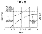
FIG. 5 is a characteristic diagram showing a relationship between the air-side heat transfer rate k and a ventilation resistance ΔP and h1/h according to the first example of the present disclosure. -
FIG. 6 is a characteristic diagram showing a relationship between the air-side heat transfer rate k and the ventilation resistance ΔP and θ according to the first example of the present disclosure. -
FIG. 7 is a plan view of fins of a heat exchanger according to an embodiment of the present invention in the x-y plane. -
FIG. 8 is a plan view of fins of a heat exchanger according to a second example of the present disclosure in the x-y plane. -
FIG. 9 is a side view of fins of the heat exchanger according to the second example of the present disclosure in the z-y plane viewed in the x direction. -
FIG. 10 is a plan view of fins of a heat exchanger according to a third example of the present disclosure in the x-y plane. -
FIG. 11 is a plan view of fins of a heat exchanger according to a fourth example of the present disclosure in the x-y plane. -
FIG. 12 is a side view of fins of the heat exchanger according to the fourth example of the present disclosure in the z-y plane viewed in the x direction. -
FIG. 13 is a side view of fins of a heat exchanger according to a fifth example of the present disclosure in the z-y plane viewed in the x direction. -
FIG. 14 is a plan view of fins of a heat exchanger according to a sixth example of the present disclosure in the x-y plane. -
FIG. 15 is a side view of fins of the heat exchanger according to the sixth example of the present disclosure in the z-y plane viewed in the x direction. -
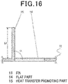
FIG. 16 is a cross-sectional view of the heat exchanger according to the sixth example of the present disclosure taken along the line indicated by the arrows A. -
FIG. 17 is a characteristic diagram showing a relationship between the air-side heat transfer rate k and the ventilation resistance ΔP and α according to the sixth example of the present disclosure. -
FIG. 18 is a plan view of fins of a heat exchanger according to a first modification of the sixth example of the present disclosure in the x-y plane. -
FIG. 19 is a side view of fins of the heat exchanger according to the first modification of the sixth example in the z-y plane viewed in the x direction. -
FIG. 20 is a plan view of fins of a heat exchanger according to a second modification of the sixth example of the present disclosure in the x-y plane. -
FIG. 21 is a side view of fins of the heat exchanger according to the second modification of the sixth example of the present disclosure in the z-y plane viewed in the x direction. -
FIG. 22 is a characteristic diagram showing a relationship between the air-side heat transfer rate k and the ventilation resistance ΔP and l1/l according to the second modification of the sixth example of the present disclosure. -
FIG. 23 is a side view of fins of a heat exchanger according to a third modification of the sixth example of the present disclosure in the z-y plane viewed in the x direction. -
FIG. 24 is a plan view of fins of a conventional heat exchanger in an x-y plane. - The invention is a heat exchanger, comprising: a plurality of plate-shaped fins arranged at predetermined intervals; and a plurality of flat pipes that are arranged in parallel with each other and having an upstream and a downstream side, wherein the flat pipes are inserted into the fins from the downstream side so that a length direction of each flat pipe is orthogonal to the fins, and have a plurality of coolant flow channels, wherein the upstream side is defined as a side on which a side surface of the flat pipes forms a front edge part, the downstream side is defined as a side on which a side surface of the flat pipes forms a rear edge part and an air flow direction is defined as a direction from the upstream side to the downstream side, wherein the fins include flat parts and heat transfer promoting parts raised from the flat parts, wherein exactly two heat transfer promoting parts are arranged symmetrically with respect to a center line between adjacent flat pipes, wherein the heat transfer promoting parts are arranged between a central part in the width direction of the flat pipe and the rear edge part of the flat pipe with respect to the air flow direction, and wherein a boundary line formed by each heat transfer promoting part and the flat part and extending from the upstream side to the downstream side is inclined with respect to the air flow direction to come closer to the adjacent flat pipe in a direction towards the upstream side.
- With such a configuration, the air passing through the gaps between the plurality of adjacent flat pipes collides with a surface of the heat transfer promoting part raised from the boundary line to form a flow toward a side surface of the flat pipe, so that the boundary layer on the side surface of the flat pipe is reduced in thickness.
- Therefore, heat transfer on the other side surfaces of the flat pipe than the front edge part can be promoted, so that the amount of heat exchanged with the coolant flowing in coolant flow channels in the other parts than the front edge parts of the plurality of coolant flow channels formed in the flat pipe increases, and the heat exchange capability can be improved.
- According to an embodiment, the heat transfer promoting part has a shape such that the flat part is cut, and a cut part of the flat part is raised along the boundary line.
- By providing the cut-and-raised part as described above, the rise angle of the heat transfer promoting part from the flat part can be increased.
- The air colliding with the surface of the heat transfer promoting part raised from the boundary line is prevented from getting over the heat transfer promoting part, and an air flow toward the side surface of the flat pipe is formed with reliability, so that the boundary layer at the side surface of the flat pipe is further reduced in thickness.
- Therefore, even in a high capacity operation in which the speed of the air flow is higher, heat transfer on the other side surfaces of the flat pipe than the front edge part can be promoted, so that the amount of heat exchanged with the coolant flowing in coolant flow channels in other parts than the front edge parts of the plurality of coolant flow channels formed in the flat pipe increases, and the heat exchange capability can be improved.
- In the following, examples of the present disclosure and embodiments of the present invention will be described with reference to the drawings. Note that the present invention is not limited to these embodiments.
-
FIG. 1 is a perspective view of a heat exchanger. An x direction is an air flow direction, a y direction is a direction of arrangement of flat pipes, and a z direction is a direction of arrangement of fins. - In
FIG. 1 , aheat exchanger 10 includes a plurality of plate-shapedfins 11 arranged at predetermined intervals and a plurality offlat pipes 12 arranged in parallel with each other and perpendicularly inserted into the plurality offins 11, and exchanges heat between air flowing between the plurality offins 11 and a coolant flowing in a plurality ofcoolant flow channels 13 formed in the plurality offlat pipes 12. - As the coolant, R410A, R32 or a mixture coolant containing R32 is used, for example. The
flat pipes 12 may be connected to form a single pipe or may be separate pipes. Each of theflat pipes 12 may have a plurality of inlet ports or outlet ports. -
FIG. 2 is a plan view of fins of the heat exchanger in an x-y plane, andFIG. 3 is a side view of fins of the heat exchanger in a z-y plane viewed in the x direction. - A y-direction side surface of the
flat pipe 12 located on an upstream side of the air flow (in the -x direction) forms afront edge part 12a, and a y-direction side surface of theflat pipe 12 located on a downstream side of the air flow (in the +x direction) forms arear edge part 12b. - The
fin 11 is formed by aflat part 14 and a heattransfer promoting part 15 that rises from theflat part 14 to the side of a passage of the air flow (in the +z direction). - The heat
transfer promoting part 15 has a V-shape and extends obliquely with respect to the air flow direction (x direction). A part of the heattransfer promoting part 15 is provided between adjacentflat pipes 12 and between thefront edge part 12a and therear edge part 12b of eachflat pipe 12. - Of boundary lines formed by the heat
transfer promoting part 15 and theflat part 14, aboundary line 16 that is substantially in parallel with a ridge of the heattransfer promoting part 15 and located on the upstream side of the air flow and has a greater dimension extends from the upstream side to the downstream side of the air flow and is inclined to come closer to theflat pipe 12. - The heat
transfer promoting part 15 further has a heattransfer promoting surface 17 that rises from theboundary line 16 with which the air collides. - An end part of the
boundary line 16 on the downstream side of the air flow (in the +x direction) is located upstream from therear edge part 12b of theflat pipe 12 in the direction of the air flow (in the -x direction). A line L1, which is an extension of the ridge of the heattransfer promoting part 15 on the downstream side of the air flow (in the +x direction), is inclined θ° with respect to the direction of the air flow (the +x direction) and intersects with theflat pipe 12 at a point upstream from therear edge part 12b of theflat pipe 12 in the direction of the air flow (in the -x direction). - Next, the air flow will be described.
- A part of the air flowing into gaps between the
fins 11 collides with thefront edge parts 12a of theflat pipes 12, and another part of the air does not collide with theflat pipes 12 but passes through the plurality of adjacentflat pipes 12. - At the
front edge part 12a of theflat pipe 12 with which the air collides, a boundary layer is reduced in thickness, so that the heat transfer rate is highest in theflat pipe 12. The boundary layer around theflat pipe 12 increases in thickness and the heat transfer rate of theflat pipe 12 decreases as it goes toward the downstream side of the air flow (in the +x direction) - The air having collided with the
front edge part 12a of eachflat pipe 12 exchanges heat with the coolant flowing in acoolant flow channel 13 on the side of thefront edge part 12a of theflat pipe 12 and then passes through the gaps between the adjacentflat pipes 12. - The air passing through the gaps between the adjacent
flat pipes 12 collides with the heattransfer promoting surfaces 17 of the heattransfer promoting parts 15 provided on thefins 11, which promotes the heat transfer with thefins 11. - As the air experiences heat exchange on the upstream side of the air flow, the temperature of the air comes closer to the temperature of the coolant flowing in each
coolant flow channel 13 of theflat pipe 12. Thus, the difference in temperature between the air and the coolant decreases as the air flows to the downstream side of the air flow. - With the heat exchanger configured as described above, the air flowing between the plurality of adjacent
flat pipes 12 collides with the heattransfer promoting surface 17 of each heattransfer promoting part 15 and then is guided along the heattransfer promoting surface 17 toward a side surface of theflat pipe 12, so that the boundary layer at the side surface of theflat pipe 12 is reduced in thickness. - As a result, heat transfer on other side surfaces of each
flat pipe 12 than thefront edge part 12a can be promoted, and therefore, the amount of heat exchanged with the coolant flowing incoolant flow channels 13 formed in other parts of eachflat pipe 12 than thefront edge part 12a can be increased, and the heat exchange capability can be improved. - A length of the
flat pipe 12 in a longer-side direction (the x direction) is denoted by w, a distance from an intersection A between the line L1 and a line that extends in the direction of the air flow (the x direction) and passes through a center of theflat pipe 12 in a shorter-side direction (the y direction) to therear edge part 12b of theflat pipe 12 is denoted by W1, a distance betweenadjacent fins 11 is denoted by h, and a height of the heattransfer promoting part 15 in the +z direction is denoted by h1.FIG. 4 is a characteristic diagram showing a relationship between an air-side heat transfer rate k and w1/w,FIG. 5 is a characteristic diagram showing a relationship between the air-side heat transfer rate k and a ventilation resistance ΔP and h1/h, andFIG. 6 is a characteristic diagram showing a relationship between the air-side heat transfer rate k and the ventilation resistance ΔP and the angle θ. In the first example, the length w in the longer-side direction (the x direction) of theflat pipe 12 is 16 mm (w = 16 mm), and the distance h betweenadjacent fins 11 is 1.3 mm (h = 1.3 mm). - As shown in
FIG. 4 , as w1 decreases, k increases, and the heat exchange capability improves. If the heattransfer promoting part 15 is arranged so that w1 ≤ 0.45w, the heat exchanger can have a high heat transfer capability. Therefore, the heattransfer promoting part 15 is desirably arranged so that w1 ≤ 7.2 mm, since w = 16 mm. By setting w1 ≤ 7.2 mm, the boundary layer around theflat pipe 12, which increases in thickness as it goes to the downstream side of the air flow (in the +x direction), can be reduced in thickness, so that heat transfer can be promoted on the other side surfaces than thefront edge part 12a of theflat pipe 12, and the heat exchange capability can be improved. - In particular, if w1 = 0 mm, the line L1 intersects with the
rear edge part 12b of theflat pipe 12, so that the air flow is more likely to be guided to the side surfaces of theflat pipe 12 closer to therear edge part 12b, at which the difference in temperature between the air and the coolant is small and heat exchange is less likely to occur, and the heat transfer on the side surfaces of theflat pipe 12 closer to therear edge part 12b can be promoted. As a result, sufficient heat exchange occurs on the entireflat pipe 12, and the heat exchange capability can be improved even in a high capacity operation in which the total coolant circulation amount is high. - As shown in
FIG. 5 , as h1 increases, k increases, and the heat exchange capability improves. In addition, ΔP increases, and an input to an air blower increases. In particular, if the heattransfer promoting part 15 is arranged so that h1 ≤ 0.60h, the heat exchanger can have a high heat exchange capability. Therefore, the heattransfer promoting part 15 is desirably arranged so that h1 ≤ 7.8 mm, since h = 1.3 mm. - With such a configuration, the air flow is more likely to be guided to the side surfaces of the
flat pipe 12 closer to therear edge part 12b, and the heat transfer on the side surfaces of theflat pipe 12 closer to therear edge part 12b can be promoted, while reducing an increase of the ventilation resistance ΔP, which is due to inhibition of the air flow (in the +x direction) so that the ventilation resistance ΔP is equal to or less than an allowable value, so that the heat exchange capability can be improved. - As shown in
FIG. 6 , as θ increases, k increases, and the heat exchange capability improves. In addition, ΔP increases, and the input to the air blower increases. In particular, the heattransfer promoting part 15 is desirably arranged so that θ ≤ 60°. - With such a configuration, the air flow is more likely to be guided to the side surfaces of the
flat pipe 12 closer to therear edge part 12b, and the heat transfer on the side surfaces of theflat pipe 12 closer to therear edge part 12b can be promoted, while reducing an increase of the ventilation resistance ΔP, which is due to contraction of the air flow that occurs when the air passes through the heattransfer promoting part 15 so that the ventilation resistance ΔP is equal to or less than an allowable value, so that the heat exchange capability can be improved. - In this example, two heat
transfer promoting parts 15 are arranged symmetrically with respect to a center line between the adjacentflat pipes 12. However, the heattransfer promoting parts 15 may not be arranged symmetrically with respect to the center line, or the number of heat transfer promoting parts may be one, three or more. Furthermore, although theboundary line 16 is showed as a straight line, of course, the same effects can be achieved if the boundary line is curved in a parabola and extends from the upstream side to downstream side of the air flow to come closer to theflat pipe 12. -
FIG. 7 is a plan view of fins of a heat exchanger according to an embodiment of the present invention in the x-y plane. - As shown in
FIG. 7 , at least one heattransfer promoting part 15 is arranged downstream, in the direction of the air flow (in the +x direction), from a central part in the width direction of theflat pipe 12 in the longer-side direction (the x direction). - With such a configuration, the air passing through the gaps between the adjacent
flat pipes 12 collides with the heattransfer promoting surface 17 of the heattransfer promoting part 15 raised from theboundary line 16 at a point downstream in the direction of the air flow (in the +x direction) from the central part in the width direction of theflat pipe 12 in the longer-side direction (the x direction). Therefore, on the downstream side of the air flow (in the +x direction), at which the difference in temperature between the air and the coolant is small and heat exchange is less likely to occur, the heattransfer promoting surface 17 of the heattransfer promoting part 15 disturbs the air flow to promote heat transfer between the air and thefin 11, so that the heat exchange capability can be improved even in a low capacity operation in which the speed of the air flow is low. -
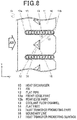
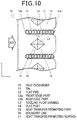
FIG. 8 is a plan view of fins of a heat exchanger according to a second example of the present disclosure in the x-y plane,FIG. 9 is a side view of fins of the heat exchanger in the z-y plane viewed in the x direction, andFIG. 10 is a plan view of fins of a heat exchanger in the x-y plane. - As shown in
FIGS. 8 and9 , the heattransfer promoting part 15 has the shape of a triangular pyramid, and the heattransfer promoting part 15 and theflat part 14 form twoboundary lines 16 on the upstream side of the air flow. Thus, a single heattransfer promoting part 15 has two heat transfer promoting surfaces 17. - The two
boundary lines 16 extend from the upstream side to the downstream side of the air flow in such a manner that theboundary lines 16 are inclined toward the respective closerflat pipes 12. The heattransfer promoting surfaces 17 raised from therespective boundary lines 16 with which the air collides are arranged in the x-y plane in such a manner that lines L2 and L3 do not intersect with each other, provided that the line L2 is a straight line that connects an apex of the heattransfer promoting part 15 in the height direction (the +z direction) and therear edge part 12b of theflat pipe 12 to each other and the line L3 is an extension of theboundary line 16 toward the flat pipe from the upstream side to the downstream side of the air flow. - With the heat exchanger configured as described above, a plurality of heat
transfer promoting parts 15 are not provided for each fin, and the air flow can be guided to the side surfaces of the plurality of adjacentflat pipes 12 by a reduced number of heattransfer promoting parts 15. Therefore, the possibility of a break or creasing of the fins can be prevented from increasing due to providing a plurality of heattransfer promoting parts 15 for each fin. - If the heat
transfer promoting part 15 is arranged so that the lines L2 and L3 are in parallel with each other, the air flow is more likely to be guided to the side surfaces of theflat pipe 12 closer to therear edge part 12b, at which the difference in temperature between the air and the coolant is smallest and heat exchange is less likely to occur, and the heat transfer on the side surfaces of theflat pipe 12 closer to therear edge part 12b can be promoted. As a result, sufficient heat exchange occurs on the entireflat pipe 12, and the heat exchange capability can be improved even in a high capacity operation in which the total coolant circulation amount is high. - Although the heat
transfer promoting part 15 has the shape of a triangular pyramid in this example, of course, the same effects can be achieved even if the heattransfer promoting part 15 has a quadrangular pyramid as shown inFIG. 10 . -
FIG. 11 is a plan view of fins of a heat exchanger according to a fourth example of the present disclosure in the x-y plane,FIG. 12 is a side view of fins of the heat exchanger in the z-y plane viewed in the x direction, andFIG. 13 is a plan view of fins of a heat exchanger in the x-y plane. - As shown in
FIGS. 11 and12 , a plurality of heattransfer promoting parts fin 11. The heattransfer promoting parts transfer promoting part 15c has the shape of a triangular pyramid and is arranged downstream in the direction of the air flow (the +x direction) from the heattransfer promoting parts - With such a configuration, the air passing through the gaps between the heat
transfer promoting parts flat pipes 12 by the heattransfer promoting part 15c arranged on the downstream side of the air flow (in the +x direction), and the heat transfer can be promoted on the entire side surfaces of theflat pipes 12, so that the heat exchange capability can be improved. - Although the plurality of heat
transfer promoting parts transfer promoting parts - Although the plurality of heat
transfer promoting parts transfer promoting parts transfer promoting part 15c is raised in the -z direction, as shown inFIG. 13 . - Furthermore, although the heat
transfer promoting parts transfer promoting part 15c is shown as having the shape of a triangular pyramid, of course, the same effects can be achieved even if different combinations of the shapes of the heat transfer promoting parts are adopted, for example, the heattransfer promoting parts transfer promoting part 15c has the shape of a quadrangular pyramid, or even if combinations of three or more shapes are adopted, for example, the heattransfer promoting part 15a has a V-shape, the heattransfer promoting part 15b has the shape of a triangular pyramid, and the heattransfer promoting part 15c has the shape of a quadrangular pyramid. -
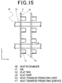
FIG. 14 is a plan view of fins of a heat exchanger according to a sixth example of the present disclosure in the x-y plane,FIG. 15 is a side view of fins of the heat exchanger in the z-y plane viewed in the x direction, andFIG. 16 is a cross-sectional view taken along the line indicated by the arrows A. - As shown in
FIGS. 14 ,15 and16 , the heattransfer promoting part 15 has a shape such that theflat part 14 is cut, and a cut part of theflat part 14 is raised along theboundary line 14 in the +z direction. - Thus, the heat
transfer promoting surface 17 of the heattransfer promoting part 15 is formed by cutting and raising, so that the rise angle α from theflat part 14 can be increased. - The heat
transfer promoting part 15 is arranged so that a line L4, which is an extension of the upper side in the +z direction of the heattransfer promoting surface 17 to the downstream side of the air flow (in the +x direction), intersects with theflat pipe 12 at a point upstream from therear edge part 12b of theflat pipe 12 in the direction of the air flow (in the -x direction). - As a result, the air colliding with the heat
transfer promoting surface 17 of the heattransfer promoting part 15 raised from theboundary line 16 is prevented from flowing in the +z direction to get over the heattransfer promoting surface 17, and the air flow toward the side surface of theflat pipe 12 is formed with reliability, so that the boundary layer at the side surface of theflat pipe 12 is further reduced in thickness. - Therefore, even in a high capacity operation in which the speed of the air flow is high, heat transfer on other side surfaces of each
flat pipe 12 than thefront edge part 12a can be promoted, and therefore, the amount of heat exchanged with the coolant flowing in thecoolant flow channels 13 formed in other parts of eachflat pipe 12 than thefront edge part 12a can be increased, and the heat exchange capability can be improved. - If the heat
transfer promoting part 15 is arranged so that the line L4 intersects with therear edge part 12b of theflat pipe 12, the air flow is more likely to be guided to the side surfaces of theflat pipe 12 closer to therear edge part 12b, at which the difference in temperature between the air and the coolant is smallest and heat exchange is less likely to occur, and the heat transfer on the side surfaces of theflat pipe 12 closer to therear edge part 12b can be promoted. As a result, sufficient heat exchange occurs on the entireflat pipe 12, and the heat exchange capability can be improved even in a high capacity operation in which the total coolant circulation amount is high. -
FIG. 17 is a characteristic diagram showing a relationship between the air-side heat transfer rate k and the ventilation resistance ΔP and the rise angle α. As α increases, k increases, and the heat exchange capability improves. In addition, ΔP increases, and the input to the air blower increases. In particular, the heattransfer promoting part 15 is desirably arranged so that 60° ≤ α ≤ 90°. - With such a configuration, an effect of disturbing the air flow to promote the heat transfer between the air and the
fins 11 due to the air having passed through the gaps between the adjacentflat pipes 12 colliding with the heattransfer promoting surface 17 of the heattransfer promoting part 15 raised from theboundary line 16 and an effect of forming the air flow toward the side surfaces of theflat pipes 12 to reduce the thickness of the boundary layers at the side surfaces of theflat pipes 12, thereby promoting the heat transfer between the air and theflat pipes 12 can be achieved, while reducing an increase of the ventilation resistance ΔP so that the ventilation resistance ΔP is equal to or less than an allowable value. - Furthermore, even if the speed of the air flow is high, the air flow is prevented from flowing in the +z direction to get over the heat
transfer promoting surface 17, and the air flow is guided to the side surfaces of theflat pipes 12 with reliability. Therefore, even in a maximum capacity operation in which the speed of the air flow is still higher, the heat exchange capability can be improved. -
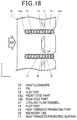
FIG. 18 is a plan view of fins of a heat exchanger according to a first modification of the sixth example of the present disclosure in the x-y plane, andFIG. 19 is a side view of fins of the heat exchanger in the z-y plane viewed in the x direction. - Of course, the same effects can be achieved even if a single heat
transfer promoting part 15 is formed by a plurality of cut-and-raised parts as shown inFIGS. 18 and19 . -
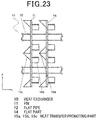
FIG. 20 is a plan view of fins of a heat exchanger according to a second modification of the sixth example in the x-y plane,FIG. 21 is a side view of fins of the heat exchanger in the z-y plane viewed in the x direction, andFIG. 23 is a side view of fins of a heat exchanger according to a third modification of the sixth example in the z-y plane viewed in the x direction. - As shown in
FIGS. 20 and21 , a plurality of heattransfer promoting parts fin 11, the heattransfer promoting parts transfer promoting part 15c has the shape of a triangular pyramid and is arranged downstream from the heattransfer promoting parts - With such a configuration, the air passing through the gaps between the heat
transfer promoting parts flat pipes 12 by the heattransfer promoting part 15c arranged on the downstream side of the air flow (in the +x direction), and the heat transfer can be promoted on the entireflat pipes 12, so that the heat exchange capability can be improved. - Although the plurality of heat
transfer promoting parts transfer promoting parts - Provided that the distance between the plurality of adjacent
flat pipes 12 is denoted by I, and the length in the y direction of the heattransfer promoting surfaces transfer promoting parts FIG. 22 is a characteristic diagram showing a relationship between the air-side heat transfer rate k and the ventilation resistance ΔP and l1/l. In the second embodiment, the distance I between the plurality of adjacentflat pipes 12 is 8.4 mm (I = 8.4 mm). - As shown in
FIG. 22 , as l1 increases, k increases, and the heat exchange capability improves. In addition, ΔP increases, and the input to the air blower increases. In particular, if the heattransfer promoting part 15 is arranged so that l1 ≤ 0.651, the heat exchanger can have a high heat exchange capability. Therefore, the heattransfer promoting part 15 is desirably arranged so that l1 ≤ 5.4 mm, since l = 8.4 mm. - With such a configuration, the air flow is more likely to be guided to the side surfaces of the
flat pipe 12 closer to therear edge part 12b, and the heat transfer on the side surfaces of theflat pipe 12 closer to therear edge part 12b can be promoted, while reducing an increase of the ventilation resistance ΔP so that the ventilation resistance ΔP is equal to or less than an allowable value, so that the heat exchange capability can be improved. - Although the plurality of heat
transfer promoting parts transfer promoting parts transfer promoting part 15c is raised in the -z direction, as shown inFIG. 23 . - Furthermore, although the heat
transfer promoting parts transfer promoting part 15c is shown as having the shape of a triangular pyramid, of course, the same effects can be achieved even if different combinations of the shapes of the heat transfer promoting parts are adopted, for example, the heattransfer promoting parts transfer promoting part 15c has shape of a quadrangular pyramid. - The present invention is a heat exchanger using a flat pipe that is improved in heat exchange capability by promoting heat transfer on the flat pipe on the downstream side of air flow and can be used in applications, such as a freezer, an air conditioner or an air conditioning and hot water supply complex system.
-
- 1
- heat exchanger
- 2
- fin
- 3
- coolant flow channel
- 4
- flat pipe
- 5
- cut-and-raised part
- 10
- heat exchanger
- 11
- fin
- 12
- flat pipe
- 12a
- front edge part
- 12b
- rear edge part
- 13
- coolant flow channel
- 14
- flat part
- 15, 15a, 15b, 15c
- heat transfer promoting part
- 16
- boundary line
- 17, 17a,
- 17b, 17c heat transfer promoting surface
Claims (3)
- A heat exchanger (10), comprising:a plurality of plate-shaped fins (11) arranged at predetermined intervals; anda plurality of flat pipes (12) that are arranged in parallel with each other and having an upstream and a downstream side, wherein the flat pipes (12) are inserted into the fins (11) from the downstream side so that a length direction of each flat pipe (12) is orthogonal to the fins (11), and have a plurality of coolant flow channels (13),wherein the upstream side is defined as a side on which a side surface of the flat pipes (12) forms a front edge part (12a), the downstream side is defined as a side on which a side surface of the flat pipes (12) forms a rear edge part (12b) and an air flow direction is defined as a direction from the upstream side to the downstream side,wherein the fins (11) include flat parts (14) and heat transfer promoting parts (15) raised from the flat parts (14),wherein exactly two heat transfer promoting parts (15) are arranged symmetrically with respect to a center line between adjacent flat pipes (12),wherein the heat transfer promoting parts (15) are arranged between a central part in the width direction of the flat pipe (12) and the rear edge part (12b) of the flat pipe (12) with respect to the air flow direction, andwherein a boundary line (16) formed by each heat transfer promoting part (15) and the flat part (14) and extending from the upstream side to the downstream side is inclined with respect to the air flow direction to come closer to the adjacent flat pipe (12) in a direction towards the upstream side.
- The heat exchanger (10) according to claim 1, wherein the heat transfer promoting part (15) has a shape such that the flat part (14) is cut, and a cut part of the flat part (14) is raised along the boundary line.
- The heat exchanger (10) according to claim 1 or 2, wherein the heat transfer promoting parts (15) have a V-shape,wherein the inclined boundary lines (16) are substantially in parallel with ridges of the respective heat transfer promoting part (15),and wherein the heat transfer promoting parts (15) have a heat transfer promoting surface (17) that rises from the inclined boundary line (16) with which air collides.
Applications Claiming Priority (1)
| Application Number | Priority Date | Filing Date | Title |
|---|---|---|---|
| JP2018000991A JP6865353B2 (en) | 2018-01-09 | 2018-01-09 | Heat exchanger |
Publications (2)
| Publication Number | Publication Date |
|---|---|
| EP3508807A1 EP3508807A1 (en) | 2019-07-10 |
| EP3508807B1 true EP3508807B1 (en) | 2021-12-22 |
Family
ID=63207563
Family Applications (1)
| Application Number | Title | Priority Date | Filing Date |
|---|---|---|---|
| EP18188111.1A Active EP3508807B1 (en) | 2018-01-09 | 2018-08-08 | Heat exchanger |
Country Status (2)
| Country | Link |
|---|---|
| EP (1) | EP3508807B1 (en) |
| JP (1) | JP6865353B2 (en) |
Citations (2)
| Publication number | Priority date | Publication date | Assignee | Title |
|---|---|---|---|---|
| US20150075213A1 (en) * | 2012-04-26 | 2015-03-19 | Mitsubishi Electric Corporation | Heat exchanger, method for fabricating heat exchanger, and air-conditioning apparatus |
| CN204787982U (en) * | 2015-07-20 | 2015-11-18 | 广东美的制冷设备有限公司 | Fin and contain its heat exchanger and air conditioner |
Family Cites Families (8)
| Publication number | Priority date | Publication date | Assignee | Title |
|---|---|---|---|---|
| JPS50134168U (en) * | 1974-04-19 | 1975-11-05 | ||
| JPS61237995A (en) * | 1985-04-12 | 1986-10-23 | Matsushita Electric Ind Co Ltd | Finned heat exchanger |
| JPS63294494A (en) * | 1987-05-27 | 1988-12-01 | Nippon Denso Co Ltd | Heat exchanger |
| JP2005201492A (en) * | 2004-01-14 | 2005-07-28 | Matsushita Electric Ind Co Ltd | Heat exchanger |
| JP4845943B2 (en) | 2008-08-26 | 2011-12-28 | 三菱電機株式会社 | Finned tube heat exchanger and refrigeration cycle air conditioner |
| US20130299153A1 (en) * | 2011-01-21 | 2013-11-14 | Daikin Industries, Ltd. | Heat exchanger and air conditioner |
| KR101224071B1 (en) * | 2012-07-05 | 2013-01-21 | 문은국 | The tube type heat exchanger |
| CN106370045B (en) * | 2016-08-30 | 2019-07-23 | 杭州三花微通道换热器有限公司 | Fin and heat exchanger having the same |
-
2018
- 2018-01-09 JP JP2018000991A patent/JP6865353B2/en active Active
- 2018-08-08 EP EP18188111.1A patent/EP3508807B1/en active Active
Patent Citations (2)
| Publication number | Priority date | Publication date | Assignee | Title |
|---|---|---|---|---|
| US20150075213A1 (en) * | 2012-04-26 | 2015-03-19 | Mitsubishi Electric Corporation | Heat exchanger, method for fabricating heat exchanger, and air-conditioning apparatus |
| CN204787982U (en) * | 2015-07-20 | 2015-11-18 | 广东美的制冷设备有限公司 | Fin and contain its heat exchanger and air conditioner |
Also Published As
| Publication number | Publication date |
|---|---|
| JP6865353B2 (en) | 2021-04-28 |
| JP2019120458A (en) | 2019-07-22 |
| EP3508807A1 (en) | 2019-07-10 |
Similar Documents
| Publication | Publication Date | Title |
|---|---|---|
| US9441890B2 (en) | Heat exchanger fin with corrugated portion and louvers | |
| EP2857785B1 (en) | Heat exchanger and air conditioner | |
| KR100252575B1 (en) | Finned Heat Exchanger | |
| KR100543599B1 (en) | heat transmitter | |
| CN101427094B (en) | Heat transmission fin and fin-tube heat exchanger | |
| US20160123681A1 (en) | Fin tube heat exchanger | |
| WO2014167845A1 (en) | Fin-and-tube heat exchanger and refrigeration cycle device | |
| CN103890527B (en) | Fin-tube heat exchanger | |
| US5553663A (en) | Heat exchange for air conditioner | |
| US5794690A (en) | Heat exchanger of air conditioner | |
| WO2009144909A1 (en) | Fin-tube heat exchanger | |
| EP1977180B1 (en) | Fin and tube heat exchanger | |
| US10801784B2 (en) | Heat exchanger with air flow passage for exchanging heat | |
| US20100175864A1 (en) | Fin tube heat exchanger | |
| JP2013092306A (en) | Fin tube heat exchanger | |
| US20060266503A1 (en) | Heat transfer fin, heat exchanger, evaporator and condenser for use in car air-conditioner | |
| EP3508807A1 (en) | Heat exchanger | |
| JP6706839B2 (en) | Fin tube heat exchanger | |
| EP3575728B1 (en) | A core of a heat exchanger comprising corrugated fins | |
| KR20110083020A (en) | heat transmitter | |
| EP4215863B1 (en) | Heat exchanger | |
| KR0133026Y1 (en) | Heat exchanger of air conditioner | |
| JP7006376B2 (en) | Heat exchanger | |
| JP2008275303A (en) | Heat exchanger | |
| JP3863034B2 (en) | Heat exchanger |
Legal Events
| Date | Code | Title | Description |
|---|---|---|---|
| PUAI | Public reference made under article 153(3) epc to a published international application that has entered the european phase |
Free format text: ORIGINAL CODE: 0009012 |
|
| STAA | Information on the status of an ep patent application or granted ep patent |
Free format text: STATUS: THE APPLICATION HAS BEEN PUBLISHED |
|
| AK | Designated contracting states |
Kind code of ref document: A1 Designated state(s): AL AT BE BG CH CY CZ DE DK EE ES FI FR GB GR HR HU IE IS IT LI LT LU LV MC MK MT NL NO PL PT RO RS SE SI SK SM TR |
|
| AX | Request for extension of the european patent |
Extension state: BA ME |
|
| STAA | Information on the status of an ep patent application or granted ep patent |
Free format text: STATUS: REQUEST FOR EXAMINATION WAS MADE |
|
| 17P | Request for examination filed |
Effective date: 20191022 |
|
| RBV | Designated contracting states (corrected) |
Designated state(s): AL AT BE BG CH CY CZ DE DK EE ES FI FR GB GR HR HU IE IS IT LI LT LU LV MC MK MT NL NO PL PT RO RS SE SI SK SM TR |
|
| STAA | Information on the status of an ep patent application or granted ep patent |
Free format text: STATUS: EXAMINATION IS IN PROGRESS |
|
| 17Q | First examination report despatched |
Effective date: 20200323 |
|
| GRAP | Despatch of communication of intention to grant a patent |
Free format text: ORIGINAL CODE: EPIDOSNIGR1 |
|
| STAA | Information on the status of an ep patent application or granted ep patent |
Free format text: STATUS: GRANT OF PATENT IS INTENDED |
|
| INTG | Intention to grant announced |
Effective date: 20210715 |
|
| GRAS | Grant fee paid |
Free format text: ORIGINAL CODE: EPIDOSNIGR3 |
|
| GRAA | (expected) grant |
Free format text: ORIGINAL CODE: 0009210 |
|
| STAA | Information on the status of an ep patent application or granted ep patent |
Free format text: STATUS: THE PATENT HAS BEEN GRANTED |
|
| AK | Designated contracting states |
Kind code of ref document: B1 Designated state(s): AL AT BE BG CH CY CZ DE DK EE ES FI FR GB GR HR HU IE IS IT LI LT LU LV MC MK MT NL NO PL PT RO RS SE SI SK SM TR |
|
| REG | Reference to a national code |
Ref country code: GB Ref legal event code: FG4D |
|
| REG | Reference to a national code |
Ref country code: CH Ref legal event code: EP |
|
| REG | Reference to a national code |
Ref country code: DE Ref legal event code: R096 Ref document number: 602018028436 Country of ref document: DE |
|
| REG | Reference to a national code |
Ref country code: AT Ref legal event code: REF Ref document number: 1457330 Country of ref document: AT Kind code of ref document: T Effective date: 20220115 |
|
| REG | Reference to a national code |
Ref country code: IE Ref legal event code: FG4D |
|
| REG | Reference to a national code |
Ref country code: LT Ref legal event code: MG9D |
|
| PG25 | Lapsed in a contracting state [announced via postgrant information from national office to epo] |
Ref country code: RS Free format text: LAPSE BECAUSE OF FAILURE TO SUBMIT A TRANSLATION OF THE DESCRIPTION OR TO PAY THE FEE WITHIN THE PRESCRIBED TIME-LIMIT Effective date: 20211222 Ref country code: LT Free format text: LAPSE BECAUSE OF FAILURE TO SUBMIT A TRANSLATION OF THE DESCRIPTION OR TO PAY THE FEE WITHIN THE PRESCRIBED TIME-LIMIT Effective date: 20211222 Ref country code: FI Free format text: LAPSE BECAUSE OF FAILURE TO SUBMIT A TRANSLATION OF THE DESCRIPTION OR TO PAY THE FEE WITHIN THE PRESCRIBED TIME-LIMIT Effective date: 20211222 Ref country code: BG Free format text: LAPSE BECAUSE OF FAILURE TO SUBMIT A TRANSLATION OF THE DESCRIPTION OR TO PAY THE FEE WITHIN THE PRESCRIBED TIME-LIMIT Effective date: 20220322 |
|
| REG | Reference to a national code |
Ref country code: NL Ref legal event code: MP Effective date: 20211222 |
|
| REG | Reference to a national code |
Ref country code: AT Ref legal event code: MK05 Ref document number: 1457330 Country of ref document: AT Kind code of ref document: T Effective date: 20211222 |
|
| PG25 | Lapsed in a contracting state [announced via postgrant information from national office to epo] |
Ref country code: SE Free format text: LAPSE BECAUSE OF FAILURE TO SUBMIT A TRANSLATION OF THE DESCRIPTION OR TO PAY THE FEE WITHIN THE PRESCRIBED TIME-LIMIT Effective date: 20211222 Ref country code: NO Free format text: LAPSE BECAUSE OF FAILURE TO SUBMIT A TRANSLATION OF THE DESCRIPTION OR TO PAY THE FEE WITHIN THE PRESCRIBED TIME-LIMIT Effective date: 20220322 Ref country code: LV Free format text: LAPSE BECAUSE OF FAILURE TO SUBMIT A TRANSLATION OF THE DESCRIPTION OR TO PAY THE FEE WITHIN THE PRESCRIBED TIME-LIMIT Effective date: 20211222 Ref country code: HR Free format text: LAPSE BECAUSE OF FAILURE TO SUBMIT A TRANSLATION OF THE DESCRIPTION OR TO PAY THE FEE WITHIN THE PRESCRIBED TIME-LIMIT Effective date: 20211222 Ref country code: GR Free format text: LAPSE BECAUSE OF FAILURE TO SUBMIT A TRANSLATION OF THE DESCRIPTION OR TO PAY THE FEE WITHIN THE PRESCRIBED TIME-LIMIT Effective date: 20220323 |
|
| PG25 | Lapsed in a contracting state [announced via postgrant information from national office to epo] |
Ref country code: NL Free format text: LAPSE BECAUSE OF FAILURE TO SUBMIT A TRANSLATION OF THE DESCRIPTION OR TO PAY THE FEE WITHIN THE PRESCRIBED TIME-LIMIT Effective date: 20211222 |
|
| PG25 | Lapsed in a contracting state [announced via postgrant information from national office to epo] |
Ref country code: SM Free format text: LAPSE BECAUSE OF FAILURE TO SUBMIT A TRANSLATION OF THE DESCRIPTION OR TO PAY THE FEE WITHIN THE PRESCRIBED TIME-LIMIT Effective date: 20211222 Ref country code: SK Free format text: LAPSE BECAUSE OF FAILURE TO SUBMIT A TRANSLATION OF THE DESCRIPTION OR TO PAY THE FEE WITHIN THE PRESCRIBED TIME-LIMIT Effective date: 20211222 Ref country code: RO Free format text: LAPSE BECAUSE OF FAILURE TO SUBMIT A TRANSLATION OF THE DESCRIPTION OR TO PAY THE FEE WITHIN THE PRESCRIBED TIME-LIMIT Effective date: 20211222 Ref country code: PT Free format text: LAPSE BECAUSE OF FAILURE TO SUBMIT A TRANSLATION OF THE DESCRIPTION OR TO PAY THE FEE WITHIN THE PRESCRIBED TIME-LIMIT Effective date: 20220422 Ref country code: ES Free format text: LAPSE BECAUSE OF FAILURE TO SUBMIT A TRANSLATION OF THE DESCRIPTION OR TO PAY THE FEE WITHIN THE PRESCRIBED TIME-LIMIT Effective date: 20211222 Ref country code: EE Free format text: LAPSE BECAUSE OF FAILURE TO SUBMIT A TRANSLATION OF THE DESCRIPTION OR TO PAY THE FEE WITHIN THE PRESCRIBED TIME-LIMIT Effective date: 20211222 Ref country code: CZ Free format text: LAPSE BECAUSE OF FAILURE TO SUBMIT A TRANSLATION OF THE DESCRIPTION OR TO PAY THE FEE WITHIN THE PRESCRIBED TIME-LIMIT Effective date: 20211222 |
|
| PG25 | Lapsed in a contracting state [announced via postgrant information from national office to epo] |
Ref country code: PL Free format text: LAPSE BECAUSE OF FAILURE TO SUBMIT A TRANSLATION OF THE DESCRIPTION OR TO PAY THE FEE WITHIN THE PRESCRIBED TIME-LIMIT Effective date: 20211222 Ref country code: AT Free format text: LAPSE BECAUSE OF FAILURE TO SUBMIT A TRANSLATION OF THE DESCRIPTION OR TO PAY THE FEE WITHIN THE PRESCRIBED TIME-LIMIT Effective date: 20211222 |
|
| REG | Reference to a national code |
Ref country code: DE Ref legal event code: R097 Ref document number: 602018028436 Country of ref document: DE |
|
| PG25 | Lapsed in a contracting state [announced via postgrant information from national office to epo] |
Ref country code: IS Free format text: LAPSE BECAUSE OF FAILURE TO SUBMIT A TRANSLATION OF THE DESCRIPTION OR TO PAY THE FEE WITHIN THE PRESCRIBED TIME-LIMIT Effective date: 20220422 |
|
| PLBE | No opposition filed within time limit |
Free format text: ORIGINAL CODE: 0009261 |
|
| STAA | Information on the status of an ep patent application or granted ep patent |
Free format text: STATUS: NO OPPOSITION FILED WITHIN TIME LIMIT |
|
| PG25 | Lapsed in a contracting state [announced via postgrant information from national office to epo] |
Ref country code: DK Free format text: LAPSE BECAUSE OF FAILURE TO SUBMIT A TRANSLATION OF THE DESCRIPTION OR TO PAY THE FEE WITHIN THE PRESCRIBED TIME-LIMIT Effective date: 20211222 Ref country code: AL Free format text: LAPSE BECAUSE OF FAILURE TO SUBMIT A TRANSLATION OF THE DESCRIPTION OR TO PAY THE FEE WITHIN THE PRESCRIBED TIME-LIMIT Effective date: 20211222 |
|
| 26N | No opposition filed |
Effective date: 20220923 |
|
| PG25 | Lapsed in a contracting state [announced via postgrant information from national office to epo] |
Ref country code: SI Free format text: LAPSE BECAUSE OF FAILURE TO SUBMIT A TRANSLATION OF THE DESCRIPTION OR TO PAY THE FEE WITHIN THE PRESCRIBED TIME-LIMIT Effective date: 20211222 |
|
| PG25 | Lapsed in a contracting state [announced via postgrant information from national office to epo] |
Ref country code: MC Free format text: LAPSE BECAUSE OF FAILURE TO SUBMIT A TRANSLATION OF THE DESCRIPTION OR TO PAY THE FEE WITHIN THE PRESCRIBED TIME-LIMIT Effective date: 20211222 |
|
| REG | Reference to a national code |
Ref country code: CH Ref legal event code: PL |
|
| PG25 | Lapsed in a contracting state [announced via postgrant information from national office to epo] |
Ref country code: LU Free format text: LAPSE BECAUSE OF NON-PAYMENT OF DUE FEES Effective date: 20220808 Ref country code: LI Free format text: LAPSE BECAUSE OF NON-PAYMENT OF DUE FEES Effective date: 20220831 Ref country code: CH Free format text: LAPSE BECAUSE OF NON-PAYMENT OF DUE FEES Effective date: 20220831 |
|
| REG | Reference to a national code |
Ref country code: BE Ref legal event code: MM Effective date: 20220831 |
|
| PG25 | Lapsed in a contracting state [announced via postgrant information from national office to epo] |
Ref country code: IT Free format text: LAPSE BECAUSE OF FAILURE TO SUBMIT A TRANSLATION OF THE DESCRIPTION OR TO PAY THE FEE WITHIN THE PRESCRIBED TIME-LIMIT Effective date: 20211222 |
|
| PG25 | Lapsed in a contracting state [announced via postgrant information from national office to epo] |
Ref country code: IE Free format text: LAPSE BECAUSE OF NON-PAYMENT OF DUE FEES Effective date: 20220808 |
|
| PG25 | Lapsed in a contracting state [announced via postgrant information from national office to epo] |
Ref country code: BE Free format text: LAPSE BECAUSE OF NON-PAYMENT OF DUE FEES Effective date: 20220831 |
|
| PG25 | Lapsed in a contracting state [announced via postgrant information from national office to epo] |
Ref country code: HU Free format text: LAPSE BECAUSE OF FAILURE TO SUBMIT A TRANSLATION OF THE DESCRIPTION OR TO PAY THE FEE WITHIN THE PRESCRIBED TIME-LIMIT; INVALID AB INITIO Effective date: 20180808 |
|
| PG25 | Lapsed in a contracting state [announced via postgrant information from national office to epo] |
Ref country code: CY Free format text: LAPSE BECAUSE OF FAILURE TO SUBMIT A TRANSLATION OF THE DESCRIPTION OR TO PAY THE FEE WITHIN THE PRESCRIBED TIME-LIMIT Effective date: 20211222 |
|
| PG25 | Lapsed in a contracting state [announced via postgrant information from national office to epo] |
Ref country code: MK Free format text: LAPSE BECAUSE OF FAILURE TO SUBMIT A TRANSLATION OF THE DESCRIPTION OR TO PAY THE FEE WITHIN THE PRESCRIBED TIME-LIMIT Effective date: 20211222 |
|
| PG25 | Lapsed in a contracting state [announced via postgrant information from national office to epo] |
Ref country code: TR Free format text: LAPSE BECAUSE OF FAILURE TO SUBMIT A TRANSLATION OF THE DESCRIPTION OR TO PAY THE FEE WITHIN THE PRESCRIBED TIME-LIMIT Effective date: 20211222 |
|
| PG25 | Lapsed in a contracting state [announced via postgrant information from national office to epo] |
Ref country code: MT Free format text: LAPSE BECAUSE OF FAILURE TO SUBMIT A TRANSLATION OF THE DESCRIPTION OR TO PAY THE FEE WITHIN THE PRESCRIBED TIME-LIMIT Effective date: 20211222 |
|
| PGFP | Annual fee paid to national office [announced via postgrant information from national office to epo] |
Ref country code: GB Payment date: 20240826 Year of fee payment: 7 |
|
| PGFP | Annual fee paid to national office [announced via postgrant information from national office to epo] |
Ref country code: FR Payment date: 20240829 Year of fee payment: 7 |
|
| PGFP | Annual fee paid to national office [announced via postgrant information from national office to epo] |
Ref country code: DE Payment date: 20250820 Year of fee payment: 8 |
|
| GBPC | Gb: european patent ceased through non-payment of renewal fee |
Effective date: 20250808 |