EP3508800B1 - Hot water supply system, control device, control method and program - Google Patents
Hot water supply system, control device, control method and program Download PDFInfo
- Publication number
- EP3508800B1 EP3508800B1 EP16915103.2A EP16915103A EP3508800B1 EP 3508800 B1 EP3508800 B1 EP 3508800B1 EP 16915103 A EP16915103 A EP 16915103A EP 3508800 B1 EP3508800 B1 EP 3508800B1
- Authority
- EP
- European Patent Office
- Prior art keywords
- water heater
- water
- hot water
- time
- hot
- Prior art date
- Legal status (The legal status is an assumption and is not a legal conclusion. Google has not performed a legal analysis and makes no representation as to the accuracy of the status listed.)
- Not-in-force
Links
Images








Classifications
-
- F—MECHANICAL ENGINEERING; LIGHTING; HEATING; WEAPONS; BLASTING
- F24—HEATING; RANGES; VENTILATING
- F24D—DOMESTIC- OR SPACE-HEATING SYSTEMS, e.g. CENTRAL HEATING SYSTEMS; DOMESTIC HOT-WATER SUPPLY SYSTEMS; ELEMENTS OR COMPONENTS THEREFOR
- F24D19/00—Details
- F24D19/10—Arrangement or mounting of control or safety devices
- F24D19/1006—Arrangement or mounting of control or safety devices for water heating systems
- F24D19/1051—Arrangement or mounting of control or safety devices for water heating systems for domestic hot water
- F24D19/1063—Arrangement or mounting of control or safety devices for water heating systems for domestic hot water counting of energy consumption
-
- H—ELECTRICITY
- H02—GENERATION; CONVERSION OR DISTRIBUTION OF ELECTRIC POWER
- H02J—ELECTRIC POWER NETWORKS; CIRCUIT ARRANGEMENTS OR SYSTEMS FOR SUPPLYING OR DISTRIBUTING ELECTRIC POWER; SYSTEMS FOR STORING ELECTRIC ENERGY
- H02J13/00—Circuit arrangements for providing remote monitoring or remote control of equipment in a power distribution network
- H02J13/12—Monitoring network conditions, e.g. electrical magnitudes or operational status
-
- H—ELECTRICITY
- H02—GENERATION; CONVERSION OR DISTRIBUTION OF ELECTRIC POWER
- H02J—ELECTRIC POWER NETWORKS; CIRCUIT ARRANGEMENTS OR SYSTEMS FOR SUPPLYING OR DISTRIBUTING ELECTRIC POWER; SYSTEMS FOR STORING ELECTRIC ENERGY
- H02J13/00—Circuit arrangements for providing remote monitoring or remote control of equipment in a power distribution network
- H02J13/14—Circuit arrangements for providing remote monitoring or remote control of equipment in a power distribution network the power network being locally controlled, e.g. home energy management systems [HEMS]
-
- H—ELECTRICITY
- H02—GENERATION; CONVERSION OR DISTRIBUTION OF ELECTRIC POWER
- H02J—ELECTRIC POWER NETWORKS; CIRCUIT ARRANGEMENTS OR SYSTEMS FOR SUPPLYING OR DISTRIBUTING ELECTRIC POWER; SYSTEMS FOR STORING ELECTRIC ENERGY
- H02J3/00—Circuit arrangements for AC mains or AC distribution networks
- H02J3/12—Arrangements for adjusting voltage in AC networks by changing a characteristic of the network load
- H02J3/14—Arrangements for adjusting voltage in AC networks by changing a characteristic of the network load by switching loads on to, or off from, the networks, e.g. progressively balanced loading
-
- H—ELECTRICITY
- H02—GENERATION; CONVERSION OR DISTRIBUTION OF ELECTRIC POWER
- H02J—ELECTRIC POWER NETWORKS; CIRCUIT ARRANGEMENTS OR SYSTEMS FOR SUPPLYING OR DISTRIBUTING ELECTRIC POWER; SYSTEMS FOR STORING ELECTRIC ENERGY
- H02J2105/00—Networks for supplying or distributing electric power characterised by their spatial reach or by the load
- H02J2105/40—Networks for supplying or distributing electric power characterised by their spatial reach or by the load characterised by the loads connecting to the networks or being supplied by the networks
- H02J2105/42—Home appliances
-
- Y—GENERAL TAGGING OF NEW TECHNOLOGICAL DEVELOPMENTS; GENERAL TAGGING OF CROSS-SECTIONAL TECHNOLOGIES SPANNING OVER SEVERAL SECTIONS OF THE IPC; TECHNICAL SUBJECTS COVERED BY FORMER USPC CROSS-REFERENCE ART COLLECTIONS [XRACs] AND DIGESTS
- Y02—TECHNOLOGIES OR APPLICATIONS FOR MITIGATION OR ADAPTATION AGAINST CLIMATE CHANGE
- Y02B—CLIMATE CHANGE MITIGATION TECHNOLOGIES RELATED TO BUILDINGS, e.g. HOUSING, HOUSE APPLIANCES OR RELATED END-USER APPLICATIONS
- Y02B30/00—Energy efficient heating, ventilation or air conditioning [HVAC]
- Y02B30/70—Efficient control or regulation technologies, e.g. for control of refrigerant flow, motor or heating
-
- Y—GENERAL TAGGING OF NEW TECHNOLOGICAL DEVELOPMENTS; GENERAL TAGGING OF CROSS-SECTIONAL TECHNOLOGIES SPANNING OVER SEVERAL SECTIONS OF THE IPC; TECHNICAL SUBJECTS COVERED BY FORMER USPC CROSS-REFERENCE ART COLLECTIONS [XRACs] AND DIGESTS
- Y02—TECHNOLOGIES OR APPLICATIONS FOR MITIGATION OR ADAPTATION AGAINST CLIMATE CHANGE
- Y02B—CLIMATE CHANGE MITIGATION TECHNOLOGIES RELATED TO BUILDINGS, e.g. HOUSING, HOUSE APPLIANCES OR RELATED END-USER APPLICATIONS
- Y02B70/00—Technologies for an efficient end-user side electric power management and consumption
- Y02B70/30—Systems integrating technologies related to power network operation and communication or information technologies for improving the carbon footprint of the management of residential or tertiary loads, i.e. smart grids as climate change mitigation technology in the buildings sector, including also the last stages of power distribution and the control, monitoring or operating management systems at local level
-
- Y—GENERAL TAGGING OF NEW TECHNOLOGICAL DEVELOPMENTS; GENERAL TAGGING OF CROSS-SECTIONAL TECHNOLOGIES SPANNING OVER SEVERAL SECTIONS OF THE IPC; TECHNICAL SUBJECTS COVERED BY FORMER USPC CROSS-REFERENCE ART COLLECTIONS [XRACs] AND DIGESTS
- Y02—TECHNOLOGIES OR APPLICATIONS FOR MITIGATION OR ADAPTATION AGAINST CLIMATE CHANGE
- Y02B—CLIMATE CHANGE MITIGATION TECHNOLOGIES RELATED TO BUILDINGS, e.g. HOUSING, HOUSE APPLIANCES OR RELATED END-USER APPLICATIONS
- Y02B70/00—Technologies for an efficient end-user side electric power management and consumption
- Y02B70/30—Systems integrating technologies related to power network operation and communication or information technologies for improving the carbon footprint of the management of residential or tertiary loads, i.e. smart grids as climate change mitigation technology in the buildings sector, including also the last stages of power distribution and the control, monitoring or operating management systems at local level
- Y02B70/3225—Demand response systems, e.g. load shedding, peak shaving
-
- Y—GENERAL TAGGING OF NEW TECHNOLOGICAL DEVELOPMENTS; GENERAL TAGGING OF CROSS-SECTIONAL TECHNOLOGIES SPANNING OVER SEVERAL SECTIONS OF THE IPC; TECHNICAL SUBJECTS COVERED BY FORMER USPC CROSS-REFERENCE ART COLLECTIONS [XRACs] AND DIGESTS
- Y04—INFORMATION OR COMMUNICATION TECHNOLOGIES HAVING AN IMPACT ON OTHER TECHNOLOGY AREAS
- Y04S—SYSTEMS INTEGRATING TECHNOLOGIES RELATED TO POWER NETWORK OPERATION, COMMUNICATION OR INFORMATION TECHNOLOGIES FOR IMPROVING THE ELECTRICAL POWER GENERATION, TRANSMISSION, DISTRIBUTION, MANAGEMENT OR USAGE, i.e. SMART GRIDS
- Y04S20/00—Management or operation of end-user stationary applications or the last stages of power distribution; Controlling, monitoring or operating thereof
- Y04S20/20—End-user application control systems
- Y04S20/222—Demand response systems, e.g. load shedding, peak shaving
-
- Y—GENERAL TAGGING OF NEW TECHNOLOGICAL DEVELOPMENTS; GENERAL TAGGING OF CROSS-SECTIONAL TECHNOLOGIES SPANNING OVER SEVERAL SECTIONS OF THE IPC; TECHNICAL SUBJECTS COVERED BY FORMER USPC CROSS-REFERENCE ART COLLECTIONS [XRACs] AND DIGESTS
- Y04—INFORMATION OR COMMUNICATION TECHNOLOGIES HAVING AN IMPACT ON OTHER TECHNOLOGY AREAS
- Y04S—SYSTEMS INTEGRATING TECHNOLOGIES RELATED TO POWER NETWORK OPERATION, COMMUNICATION OR INFORMATION TECHNOLOGIES FOR IMPROVING THE ELECTRICAL POWER GENERATION, TRANSMISSION, DISTRIBUTION, MANAGEMENT OR USAGE, i.e. SMART GRIDS
- Y04S20/00—Management or operation of end-user stationary applications or the last stages of power distribution; Controlling, monitoring or operating thereof
- Y04S20/20—End-user application control systems
- Y04S20/242—Home appliances
-
- Y—GENERAL TAGGING OF NEW TECHNOLOGICAL DEVELOPMENTS; GENERAL TAGGING OF CROSS-SECTIONAL TECHNOLOGIES SPANNING OVER SEVERAL SECTIONS OF THE IPC; TECHNICAL SUBJECTS COVERED BY FORMER USPC CROSS-REFERENCE ART COLLECTIONS [XRACs] AND DIGESTS
- Y04—INFORMATION OR COMMUNICATION TECHNOLOGIES HAVING AN IMPACT ON OTHER TECHNOLOGY AREAS
- Y04S—SYSTEMS INTEGRATING TECHNOLOGIES RELATED TO POWER NETWORK OPERATION, COMMUNICATION OR INFORMATION TECHNOLOGIES FOR IMPROVING THE ELECTRICAL POWER GENERATION, TRANSMISSION, DISTRIBUTION, MANAGEMENT OR USAGE, i.e. SMART GRIDS
- Y04S20/00—Management or operation of end-user stationary applications or the last stages of power distribution; Controlling, monitoring or operating thereof
- Y04S20/20—End-user application control systems
- Y04S20/242—Home appliances
- Y04S20/244—Home appliances the home appliances being or involving heating ventilating and air conditioning [HVAC] units
Definitions
- the present disclosure relates to a hot water supply system, a control device, a control method, and a computer program.
- Patent Literature 1 a device is described that, in response to a case in which a hot water supply amount varies relative to an average hot water amount, controls a heating operation to prevent running out of hot water. This device can heat an appropriate amount of hot water even when there is large variation in the hot water supply amount.
- an objective of the present disclosure is to suppress the peak of power consumption that occurs due to operation of water heaters.
- a hot water supply system of the present disclosure includes:
- one hot water heater generates hot water prior to a time corresponding to a supply time for supply of hot water in the past.
- the generation of hot water by the corresponding water heater is suppressed.
- the operation periods of the first water heater and the second water heater are dispersed relative to each other, and therefore the peak of power consumption that occurs due to operation of these water heaters can be suppressed.
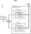
- FIG. 1 illustrates a hot water supply system 100 according to Embodiment 1.
- the hot water supply system 100 is a system that suppresses a peak of power consumption by causing dispersal of periods of operation of water heaters.
- the hot water supply system 100 includes: a control device 10 that controls hot water heaters 21 to 29 via a network 40, and water heaters 21 to 29 that generate hot water by consuming power supplied via power lines from a power source 60.
- the solid lines connecting to the network 40 in FIG. 1 indicate communication lines
- the thick solid lines connecting to the power source 60 indicates power lines.
- Examples of the network 40 include the Internet, a local area network (LAN), and a dedicated line.
- the control device 10 and the water heaters 21 to 29 perform wired communication or wireless communication via the network 40.
- the control device 10 is a server connected to the water heaters 21 to 29 via the network 40.
- the control device 10 causes dispersal of times of operation of the water heaters 21 to 29 by managing the operation states of the water heaters 21 to 29 to control the water heaters 21 to 29.
- the water heaters 21 to 29 include hot water storage tanks 211 to 219, respectively.
- the water heater 21 stores hot water generated by heating municipal tap water by a (non-illustrated) heat pump unit, and supply hot water from the hot water storage tank 211 in response to a request from a user using a facility 51 where the water heater 21 is arranged.
- the supply of hot water by the other water heaters is similar, and for example, the water heater 29 supplies hot water from the hot water storage tank 219 in response to a request from a user using a facility 59 where the water heater 29 is arranged.
- the facilities 51 to 59 are homes or buildings.
- the water heaters 21 to 29 supply hot water to a user who is an inhabitant of the home.
- the facilities 51 to 59 form power supply units 61.
- the power supply unit 61 is an aggregation of loads capable of being supplied power from the power source 60, and for example, is an aggregation of homes having facilities 51 to 59 that are homes, or is a region having facilities 51 to 59 that are buildings.
- the power source 60 for example, is a commercial power source, a distributed-type power source, or a combination of a commercial power source and a distributed-type power source.
- the power source 60 is a commercial power source and solar power generators, wind power generators, fuel cells, or a combination of such installed at the aggregation of homes.
- FIG. 2 illustrates a hardware configuration of the control device 10 and the water heater 20.
- the water heater 20 here generically indicates the water heaters 21 to 29.
- the hardware configuration of the water heater 20 illustrated in FIG. 2 is a configuration for achieving computer functions, and FIG. 2 omits the hot water storage tanks 211 to 219, heat pump units, water piping, water supply pumps, and valves.
- control device 10 and the water heater 20 are formed as a computer that includes a processor 31, a main storage 32, an auxiliary storage 33, an inputter 34, an outputter 35, and a communicator 36.
- processor 31 a main storage 32
- auxiliary storage 33 an inputter 34
- outputter 35 an outputter 35
- communicator 36 an inputter 34
- communicator 36 a communicator 36
- the processor 31 includes a central processing unit (CPU).
- the processor 31 achieves below-described functions by executing a program 38 stored in the auxiliary storage 33.
- the main storage 32 includes a random access memory (RAM).
- the main storage 32 loads the program 38 from the auxiliary storage 33. Thereafter, the main storage 32 is used as a working area of the processor 31.
- the auxiliary storage 33 includes non-volatile memory as represented by a hard disc drive (HDD) or a flash memory.
- the auxiliary storage 33 stores, in addition to the program 38, various types of data used in processing by the processor 31. Then in accordance with an instruction of the processor 31, the auxiliary storage 33 supplies to the processor 31 data used by the processor 31, and stores data supplied from the processor 31.
- the inputter 34 includes an input key and electrostatic capacitance-type pointing device.
- the inputter 34 acquires information inputted by the user, and sends notification to the processor 31.
- the outputter 35 includes a display device, as represented by a liquid crystal display (LCD), and a speaker.
- the display device of the outputter 35 according to the present embodiment includes a touch screen that is integrally formed with the pointing device that is included in the inputter 34.
- the outputter 35 regenerates a sound signal and displays to the user various types of images and text in accordance with instructions from the processor 31.
- the communicator 36 includes a communication interface circuit for communicating via the network 40 with external devices connected via communication lines.
- the communicator 36 sends notification to the processor 31 of information included in a signal received from the outside, and transmits to external equipment a signal indicating information output from the processor 31.
- FIG. 3 illustrates a functional configuration of the hot water supply system 100.
- Each of the functions of the control device 10 and the water heater 20 illustrated in FIG. 3 is achieved by coordinated operation of the aforementioned hardware.
- the control device 10 includes as functions thereof: a data acquirer 101 that acquires data from the water heater 20, a control target selector 102 that selects the water heater 20 that serves as a control target, a supply time estimator 103 that estimates a time of supply of hot water by the water heater 20, a generation time determiner 104 that determines a time for causing the water heater 20 selected as the control target to generate hot water, and a controller 105 that controls the water heater 20.
- the data acquirer 101 is mainly achieved cooperatively between the processor 31 and the communicator 36 of the control device 10.
- the data acquirer 101 repeatedly acquires from the water heater 20 data indicating supply information that includes the supply amount of hot water and the time of supply of hot water by the water heater 20.
- the data acquirer 101 acquires data that is a time series indicating the supply amount of hot water from the water heater 20.
- the data indicating the supply amount acquired by the data acquirer 101 is indicated by the solid-line bars.
- the dashed-line bars indicate estimation values of the supply amount occurring in the future. The estimation of the supply amount is described below.
- running-out-of-hot-water prevention time slots TP0, TP1, and TP2 are indicated in FIG. 4 .
- the running-out-of-hot-water prevention time slots TP0 to TP2 are described below.
- the water heater 20 runs in a water-heating mode that heats water of a target hot-water storage amount in a specific period, the target hot-water storage amount being a hot-water amount estimated, on the basis of a hot-water supply history occurring in the past, to be generated by demand in a future fixed time slot.
- the future fixed time slot according to the present embodiment is a 24 hour period, without particular limitation, and the future fixed time slot may be shorter or longer than the 24 hour period.
- the specified period according to the present embodiment is a period in which an electricity billing rate for power supplied from the commercial power supply is low, the specified period is not limited to such a period, and the specified period may be a period in which power generation is anticipated from a distributed type power source.
- the expression "heating water” means generating hot water.
- the water heater 20 Upon the water heater 20 completing operation in the water-heating mode, the water heater 20 monitors the remaining amount of hot water stored in the hot water storage tanks 211 to 219, and operates in a running-out-of-hot-water prevention mode that generates hot water of a relatively small amount when the remaining amount becomes less than a threshold.
- the remaining amount generated in the running-out-of-hot-water prevention mode in the present embodiment is the remaining amount expected to be demanded after a point in time when the remaining amount becomes less than the threshold value.
- This hot-water amount is calculated by subtracting from the target hot-water storage amount the threshold and the hot-water amount supplied after completion of running in the water-heating mode, although the calculation procedure is not limited to this calculation method.
- the water heater 20 operates again in the water-heating mode in the specified period.
- the running-out-of-hot-water prevention time slots TP0 to TP2 indicated in FIG. 4 are time slots in which the water heater 20 runs in the running-out-of-hot-water prevention mode.
- the specified period of operation in the water-heating mode of the water heaters 21 to 29 for receiving the supply of power from the common power source 60 is normally used in common by the water heaters 21 to 29. That is, the running-out-of-hot-water prevention time slots TP0 to TP2 are used in common by the water heaters 21 to 29.
- the control target selector 102 is mainly achieved by the processor 31 of the control device 10.
- the control target selector 102 determines a unit count of the water heaters 20 serving as the control targets.
- the unit count of the water heaters 20 serving as the control targets is at least one and is less than the total count of the water heaters 20.
- the control target selector 102 selects, from among the water heaters 21 to 29, a water heater 20 that has a high probability of generating hot water in the future running-out-of-hot-water prevention time slot TP2.
- the supply time estimator 103 is mainly achieved by the processor 31 of the control device 10.
- the supply time estimator 103 estimates the time of supply of hot water by the water heater 20 in the future running-out-of-hot-water prevention time slot TP2.
- the supply of hot water estimated by the supply time estimator 103 is indicated by the dashed-line bars.
- the supply time estimator 103 uses the time when the supply amount of hot water becomes maximum in the running-out-of-hot-water prevention time slot TP1 as the estimation time for the supply of hot water in the running-out-of-hot-water prevention time slot TP2. Further, the supply time estimator 103 estimates the maximum hot-water amount supplied in the running-out-of-hot-water prevention time slot TP1 to also be supplied in the running-out-of-hot-water prevention time slot TP2.
- the time of occurrence of demand for a small amount of hot water is not fixed, and estimating this time of occurrence is considered to be difficult.
- the time of the maximum supply amount of hot water corresponds to the time of bathing, and the demand for hot water is assumed to occur similarly to such demand in the previous day.
- the supply time estimator 103 estimates the supply of hot water to occur in the running-out-of-hot-water prevention time slot TP2.
- the hot water demand occurring in response to bathing is generally concentrated in the evening through nighttime, and the supply time estimator 103 estimates that a comparatively large amount of hot water supply is concentrated in the evening through nighttime in the running-out-of-hot-water prevention time slot TP2.
- the power consumption for generation of hot water by the hot water heater 20 is also concentrated in the evening through nighttime.
- the concentration of power consumption by operation of the water heaters 21 to 29 in this manner is indicated by a line LI.
- the generation time determiner 104 is mainly achieved by the processor 31 of the control device 10.
- the generation time determiner 104 determines the time for causing generation of hot water by some of the water heaters 20 selected as the control target. This time is a time prior to the time estimated for the supply of hot water by the control target water heater 20.
- the power consumption due to operation of the water heaters 21 to 29 when causing the portion of the water heaters 20 to generate hot water prior to the time estimated for the supply of hot water is indicated by the line L2 in FIG. 5 . Due to shifting of a portion of the energy consumption of the peak indicated by a line L1, as indicated by the line L2, the peak value of power consumption is understood to be reduced from P1 to P2.
- the controller 105 is mainly achieved cooperatively by the processor 31 and the communicator 36 of the control device 10.
- the controller 105 controls the water heater 20 selected as the control target, and thus causes the water heater 20 to generate hot water at the time determined by the generation time determiner 104.
- the water heater 20 includes as functions thereof: a supply amount measurer 201 that measures the supply amount of hot water by a non-illustrated flowrate sensor, a supply information notifier 202 that sends notification to the control device 10 of the measurement result due to measurement by the supply amount measurer 201, and a generator 203 that generates hot water in response to a control signal transmitted from the control device 10.
- the supply information notifier 202 periodically sends notification of the supply amount of hot water.
- the cycle of this notification for example, is 1 minute long, 5 minutes long, or 30 minutes long.
- the control device 10 can use the time of receiving of the notification as the time for supplying hot water.
- the supply information notifier 202 may transmit to the control device 10 the data indicating the time of occurrence of the supply of hot water in association with data indicating the supply amount of hot water.
- control processing executed by the control device 10 is described with reference to FIGS. 6 to 9 .
- the control processing illustrated in FIG. 6 is executed periodically.
- the cycle of execution of the control processing for example, is 10 minutes long or 1 hour long.
- the control device 10 firstly determines whether the present time is the start time of the running-out-of-hot-water prevention time slot (step S1). For example, the processor 31 of the control device 10 determines whether the present time is 6 o'clock, which is the start time of the running-out-of-hot-water prevention time slot TP2 indicated in FIG. 4 .
- step S1 In the case of determination that the present time is not the start time of the running-out-of-hot-water prevention time slot (NO in step S1), processing of the control device 10 moves to step S3. However, in the case of determination that the present time is the start time of the running-out-of-hot-water prevention time slot (YES in step S1), the control device 10 determines the unit count of the water heaters 20 serving as the control target (step S2). Specifically, in a state in which all the water heaters 20 are taken to not be selected, the control target selector 102 determines that the unit count of the control target water heaters 20 is one half the total number of all of the water heaters 20. Thus the control device 10 newly selects only the determined unit count of water heaters 20 to serve as the control target.
- control target selector 102 of the control device 10 assigns an ordering of all the water heaters 20 in ascending order of the remaining amount of hot water, in ascending order of a difference between the threshold for generation of hot water and the remaining amount, or in ascending order of a hot-water amount to be generated (step S3).
- all the water heaters 20 are sorted in order of height of probability that hot water is generated in the running-out-of-hot-water prevention time slot.
- control device 10 assigns a value of 1 to a variable m that is used for distinguishing all the water heaters 20 in the ordering assigned instep S3 (step S4). That is, if m is 1, then the m-th water heater 20 corresponds to the water heater 20 that has the highest probability of generating hot water in the running-out-of-hot-water prevention time slot.
- control device 10 determines whether a water heater 20 exists that is unselected (step S5). That is to say, the control target selector 102 determines whether the unit count of the previously selected water heaters 20 has reached the unit count determined in step S2.
- step S5 Upon determination that no water heaters 20 exist that are not selected (NO in step S5), the control device 10 ends the control processing. However, upon determination that a water heater 20 exists that is not selected (YES in step S5), the supply time estimator 103 of the control device 10 estimates the supply time of the m-th water heater 20 (step S6). The estimation procedure of this supply time is described with reference to FIGS. 7 and 8 for an example different from the example illustrated in FIG. 4 .
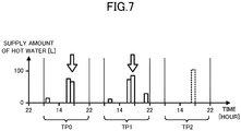
- FIG. 7 illustrates an example of estimation, as the supply time of hot water occurring in the running-out-of-hot-water prevention time slot TP2, the time, in the running-out-of-hot-water prevention time slot TP1, when the hot water supply amount increases to more than that of the past running-out-of-hot-water prevention time slot TP0.
- the supply amount of hot water at the time indicated by the outlined-type arrow increases at the running-out-of-hot-water prevention time slot TP1 from that of running-out-of-hot-water prevention time slot TP0.
- the supplying of hot water is estimated to also occur in the future running-out-of-hot-water prevention time slot TP2.
- FIG. 8 illustrates an example of estimation, as the supply time of hot water occurring in the running-out-of-hot-water prevention time slot TP2, a time in which hot water is supplied periodically over the running-out-of-hot-water prevention time slots TP3, TP0, and TP1.
- hot water is supplied at the specific time indicated by the outlined-type arrow.
- the supplying of hot water is estimated to occur also in the future running-out-of-hot-water prevention time slot TP2.
- step S6 the control device 10 determines the generation time of hot water by the m-th water heater 20 (step S7). Specifically, the generation time determiner 104 determines as the generation time a time, in the running-out-of-hot-water prevention time slot TP2, prior to the time estimated in step S6.
- the generation time determiner 104 determines that the present time is the generation time (i) when the present time is a time prior to the time estimated in step S6, and the present time is not a time when a water heater 20 other than the m-th water heater 20 is supplying hot water, or (ii) when the present time corresponds to a time when the supply amount of hot water by another water heater 20 in the running-out-of-hot-water prevention time slot TP1 is smaller than a predetermined amount.
- the period TG1 is indicated that includes the generation time determined by the generation time determiner 104. Further, the hatched bars in FIG. 9 indicates an example of the supply of hot water by the other water heater 20 transitioning in the running-out-of-hot-water prevention time slot TP2 in the same manner as in the running-out-of-hot-water prevention time slot TP1. As illustrated in FIG. 9 , the period TG1 is prior to the time at which the m-th water heater 20 supply of hot water is estimated to occur in the running-out-of-hot-water prevention time slot TP2, and is a period in which the supply amount of hot water by the other water heater 20 is lower than a threshold TH1.
- the generation time determiner 104 preferably determines a time when there is no supply of hot water by another water heater 20, or a time when the supply of hot water is low. Such operation enables reliable dispersal of power consumption.
- step S8 the control device 10 determines whether the m-th water heater 20 is in a state calling for exclusion from being a control target (step S8). Specifically, in the case in which the present time exceeds the supply time estimated in step S6, in the case in which the m-th water heater 20 is presently operating in the water-heating mode, or in the case in which no time capable of determination by the generation time determiner 104 exists for the m-th water heater 20, the control target selector 102 determines that the m-th water heater 20 is in a state calling for exclusion from being a control target.
- step S8 Upon determination that the m-th water heater 20 is in a state calling for exclusion from being a control target (YES in step S8), processing by the control device 10 proceeds to step S10. However, upon determination that the m-th water heater 20 is not in a state calling for exclusion from being a control target (NO in step S8), the control device 10 selects the m-th water heater 20 and sets the operation status of the selected water heater 20 to the water-heating mode (step S9). Specifically, the control target selector 102 selects the m-th water heater 20 as a control target water heater 20. Further, the controller 105 controls the selected water heater 20 to cause generation of hot water by causing operation in the water-heating mode.
- the procedure for the controller 105 to cause the generation of hot water by the water heater 20 is not limited to setting to the water-heating mode, and the generation of hot water may be caused by maintaining the running-out-of-hot-water prevention mode as is.
- the generated hot-water amount may be equivalent to the hot-water amount generated in the water-heating mode, may be equivalent to the hot-water amount generated in the running-out-of-hot-water prevention mode, or may be less than the hot-water amount generated in the running-out-of-hot-water prevention mode. In the case in which the generated hot-water amount is less than the hot-water amount generated in the running-out-of-hot-water prevention mode, the peak of power consumption can be further suppressed.
- the control device 10 determines whether the value of the variable m is equal to the total count of all the water heaters 20 (step S10). In the case in which the value of the variable m is not equal to the total count of all the water heaters 20 (NO in step S10), the control device 10 adds one to the variable m (step S11) and repeats the processing of step S5 and beyond. However, in the case of determination that the value of the variable m is equal to the total count of all the water heaters 20 (YES in step S10), the control device 10 ends the control processing.
- the control device 10 selects, from among the water heaters 20, a portion of the water heaters 20, and then for the selected water heaters 20, estimates the supply time occurring in the future running-out-of-hot-water prevention time slot from the supply time at which hot water is supplied in a past running-out-of-hot-water prevention time slot. Then the control device 10 causes the generation of hot water by the selected water heater 20 prior to the estimated supply time in the future running-out-of-hot-water prevention time slot.
- Such operation at the estimated supply time, has effects such as eliminating the generation of hot water by the selected water heater 20, and reducing the hot-water amount generated by the selected water heater 20.
- the concentration of hot water demand and power consumption can be prevented beforehand. Thus the peak of power consumption can be suppressed.
- control device 10 estimates as the supply time occurring in the future running-out-of-hot-water prevention time slot: the time when the supply amount of hot water is maximum in the past running-out-of-hot-water prevention time slot, the time when the supply amount of hot water is increased in the past running-out-of-hot-water prevention time slot versus the prior running-out-of-hot-water prevention time slot, or alternatively, the time when hot water, in the past running-out-of-hot-water prevention time slot, is supplied periodically in running-out-of-hot-water prevention time slots previous thereto.
- Such operation increase accuracy of the estimation of the supply time of hot water in the future running-out-of-hot-water prevention time slot, and can make the estimation of the supply time more reliable.
- control device 10 sets, as the time for causing generation of hot water by the selected water heater 20, the time when the another water heater 20 does not supply hot water, or alternatively, the time when the supply amount of hot water from another water heater 20 in the past running-out-of-hot-water prevention time slot is smaller than the predetermined amount. Such operation enables the prevention of concentration of the period of power consumption.
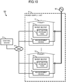
- Embodiment 2 is centered on points of difference with respect to the aforementioned Embodiment 1. Further, structures that are the same or equivalent to those of the aforementioned Embodiment 1 are assigned the same reference symbols, and description of such structures is omitted or abbreviated. As illustrated in FIG. 10 , the hot water supply system 100 according to the present embodiment differs from Embodiment 1 by including measurement devices 71 to 79 that measure power supplied via the power lines from the power source 60 to the facilities 51 to 59, respectively.
- the measurement devices 71 to 79 are installed respectively together with the water heaters 21 to 29 in the facilities 51 to 59. Also, the measurement devices 71 to 79 use current transformers (CTs) to measure power supplied respectively to the facilities 51 to 59, and periodically transmit to the control device 10 via the network 40 data indicating results of the measurements.
- CTs current transformers
- FIG. 11 illustrates functional configuration of the hot water supply system 100 according to the present embodiment.
- the control device 10 includes a collector 106 that collects measurement results from a measurement device 70.
- the collector 106 is achieved mainly cooperatively between the processor 31 and the communicator 36 of the control device 10.
- the collector 106 collects the measurement values of power transmitted from the measurement devices 71 to 79 as the measurement results.
- the measurement device 70 generically indicates the measurement devices 71 to 79.
- the control device 10 executes processing similar to the control processing illustrated in FIG. 6 .
- step S2 the control target selector 102, on the basis of a change amount of a total of the measurement values collected by the collector 106, determines the unit count of the water heaters serving as the control target. For example, in the case in which the total of the measurement values is decreasing at the present time, power supplied to the power supply unit 61 is considered to possibly not increase rapidly even if more water heaters 20 are set to the water-heating mode.
- the control target selector 102 sets as the control target water heaters 20 of a unit count that is greater than a standard value. The standard value is half the total count of all the water heaters 20.
- the control target selector 102 makes, as the control target, the water heaters 20 of a unit count that is smaller than the standard value. Such operation selects control target equipment on the basis of the change amount of the total of the measurement values.
- step S7 the generation time determiner 104 determines, as the time for generation of hot water in the future running-out-of-hot-water prevention time slot, a time at which the measurement value in the past running-out-of-hot-water prevention time slot becomes minimum.
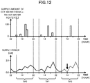
- FIG. 12 shows trending of the supply amount of hot water from the m-th water heater 20, and of power supplied to the facility in which the m-th water heater 20 is arranged.
- the trending of the running-out-of-hot-water prevention time slot TP2 indicated by the dashed line illustrates trending that is similar to that of the running-out-of-hot-water prevention time slot TP1.
- the time at which the measurement value becomes minimum is suitable as the time for causing generation of hot water by the m-th water heater 20.
- the generation time determiner 104 may determine that a time at which the total of the measurement values collected by the collector 106 becomes minimum is the time of generation of hot water.
- control device 10 on the basis of the measurement value of power, adjusts the unit count of the water heaters that become the control target. Such operation enables effective suppression of the peak of power consumption.
- control device 10 causes generation of hot water by the water heater 20 at the time when the measurement value of power becomes minimum. Such operation enables avoidance of the occurrence of the generation of the peak of power consumption.
- Embodiment 3 is centered on points of difference with respect to the aforementioned Embodiment 2. Further, structures that are the same or equivalent to those of the aforementioned Embodiment 2 are assigned the same reference symbols, and description of such structures is omitted or abbreviated.
- the hot water supply system 100 according to the present embodiment differs from Embodiment 2 in that the generation time determiner 104 determines the time of generation of hot water while additionally considering a period required for the generation of hot water.
- the control device 10 executes processing similar to that control processing illustrated in FIG. 6 .
- the present embodiment is similar to Embodiment 2 in that the generation time is set to be earlier than the time estimated in step S6, the present embodiment differs from Embodiment 2 in the specific method of determination of the time in step S7. This determination method of time is described with reference to FIGS. 13 to 16 .
- FIGS. 13 and 14 illustrate trending of total power, which is the total of power supplied to the facilities 51 to 59, in the running-out-of-hot-water prevention time slot TP2.
- the trending illustrated in FIGS. 13 and 14 is assumed to be similar to the trending of the total power in the running-out-of-hot-water prevention time slot TP1.
- the generation time determiner 104 within the running-out-of-hot-water prevention time slot TP2, scans a period P1 of a specified length, and searches for the period P1 at which an integrated value of the total power is less than or equal to a predetermined threshold.
- the length of the period P1 is the length of time required for generation of hot water, and for example, may be an average length of the period required for generation of hot water, or may be the length of the period calculated from the hot-water amount to be generated by the control target water heater 20. Further, the length of the period P1 may be set beforehand at the time of shipment from a factory, or may be input by the user. Further, the integrated value of the total power is equal to the energy indicated by the regions A1 and A2 indicated by hatching in FIGS. 13 and 14 .
- the generation time determiner 104 determines that the time for generation of hot water is a time belonging to the period P1 indicated in FIG. 14 .
- control device 10 in addition to considering the period required for generation of hot water, determines the period for generation of hot water to be the period in which the integrated value of the total power is less than or equal to the threshold.
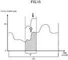
- FIG. 15 is used to describe a case in which the period required for generation of hot water is not considered.
- FIG. 15 illustrates trending of the total power when the time at which the total power is minimum is determined to be the generation time of hot water, and hot water is generated after the determined generation time.
- the period P1 required for generation of hot water starts from the time when the total power is minimum, the total power greatly increases in the period P1.
- the trending of the total power changes as indicated by the outlined-type arrow in FIG. 15 , and as a result, a peak of power consumption, such as that indicated by the black arrow, may occur during the generation of hot water.
- hot water is generated in a period when the integrated value of the total power is less than or equal to the threshold, and thus avoiding the generation of the peak of power consumption is considered to be possible.
- the generation time determiner 104 may determine the period for generation of hot water to be the period PI, which is formed from multiple time slots, in which the integrated value of the total power occurring in each of the time slots is less than a predetermined threshold value. That is to say, a time belonging to the period P1, in which all the integrated values indicated by the areas of the regions A3, A4, and A5 are smaller than the threshold, may be determined to be the time for generation of hot water. If the total energies of each of the time slots forming the period P1 are each less than or equal to the threshold, even though hot water is generated in the period P1, the generation of the peak of power consumption is considered to be unlikely. Further, the length of each of the time slots may be set to, 5 minutes, 30 minutes, or 1 hour.
- the generation time determiner 104 may determine as the time for generation of hot water a time included in the period P1 in which the trending of the total power does not exceed a predetermined threshold TH2. If hot water is generated in the period P1 when the trending of the total power does not exceed the threshold value TH2, the generation of the peak of the power consumption is considered to be unlikely.
- a facility-internal controller that controls the water heater 20 and the measurement device 70 may be installed in each of the facilities 51 to 59, and the control device 10 may communicate with the water heater 20 and the measurement device 70 via the facility-internal controllers.
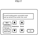
- control device 10 by display of a screen image such as the example indicated in FIG. 17 , may provide to the user notification of the control state and a control reason.
- the measurement value measured by the measurement devices 71 to 79 is preferably a measurement value of power minus power consumed by the water heaters 21 to 29.
- the control device 10 shifts and adjusts the period for generation of energy consumption of the water heater.
- adjustment is further performed on the basis of the post-adjustment trending of power, and control by the control device 10 is considered to be inappropriate.
- the control device 10 can execute the appropriate control on the basis of the measurement value of power minus the power consumed by the water heaters 21 to 29.
- the measurement values measured by the measurement devices 71 to 79 are equal to the power actually consumed in the facilities 51 to 59.
- the measurement devices 71 to 79 may measure the power supplied to the facilities 51 to 59 by summing the power consumption of each equipment arranged in the facilities 51 to 59.
- the measurement devices 71 to 79 may acquire or possess data associating the operation status and the power consumption of the equipment, may acquire the operation status of the equipment by communication with the equipment, and may obtain the power consumption of the equipment from the acquired operation status.
- the power occurring in the future running-out-of-hot-water prevention time slot is considered to be equal to the measurement value occurring in the past running-out-of-hot-water prevention time slot.
- the measurement value of power occurring in the past running-out-of-hot-water prevention time slot includes the measurement value of power occurring in the previous-slot running-out-of-hot-water prevention time slot, although this configuration is not limiting.
- the measurement value of the past running-out-of-hot-water prevention time slot may be forecast by the trending of power occurring in the future running-out-of-hot-water prevention time slot on the basis of trending that occurs multiple past running-out-of-hot-water prevention time slots.
- the forecast value of power may be an average value of the measurement value occurring in two or more past running-out-of-hot-water prevention time slots. Further, the forecast value of the power may be an average value obtained by multiplying a large weighing coefficient times the measurement value occurring in a later running-out-of-hot-water prevention time slot among the multiple running-out-of-hot-water prevention time slots. Further, the forecast value of the power may be a time series of maximum values that combine maxima extracted from the past multiple running-out-of-hot-water prevention time slots.
- the measurement value measured by the measurement devices 71 to 79 may be an instantaneous value, or may be a measurement value of energy or average power occurring in a time segment having a certain appropriate length.
- the time segment length for example, may be 30 minutes or 1 hour.
- control processing illustrated in FIG. 6 is repeatedly executed, this configuration is not limited.
- the control device 10 may create a control schedule occurring in the running-out-of-hot-water prevention time slot, and may control the water heater 20 in accordance with the created control schedule, or alternatively, the control device 10 may control the water heater 20 by transmitting to the water heater 20 the created control schedule.
- control device 10 and the water heater 20 in the aforementioned embodiments can be achieved by dedicated hardware, or by a general computer system.
- a program 38 recorded on the auxiliary storage 33 of the control device 10 and the water heater 20 may be distributed on a computer-readable recording medium such as a flexible disc, compact disc read-only memory (CD-ROM), digital versatile disc (DVD), and the like may be distributed, and the program 38 may be installed on a computer to form a device that executes the aforementioned processing.
- a computer-readable recording medium such as a flexible disc, compact disc read-only memory (CD-ROM), digital versatile disc (DVD), and the like may be distributed, and the program 38 may be installed on a computer to form a device that executes the aforementioned processing.
- the program 38 may be stored on a disc device included in a server on a communication network such as the Internet, and for example, may be superimposed on a carrier wave, and then downloaded to the computer.
- processing can be achieved by starting and running the program 38 while transferring the program 38 via the communication network.
- processing can be achieved by executing all or part of the program 38 on the server device and executing the program 38 while the computer receives and transmits information relating to the processing via the communication network.
- the program other than the OS may be stored on the above recording medium for distribution or may be downloaded to the computer.
- control device 10 and the water heater 20 is not limited to software, and the functions may be achieved by a portion or all the functions being achieved by dedicating hardware that includes circuits.
- the present disclosure is suitable for operation of a water heater that consumes power and generates hot water.
Landscapes
- Engineering & Computer Science (AREA)
- Power Engineering (AREA)
- Physics & Mathematics (AREA)
- Thermal Sciences (AREA)
- Chemical & Material Sciences (AREA)
- Combustion & Propulsion (AREA)
- Mechanical Engineering (AREA)
- General Engineering & Computer Science (AREA)
- Heat-Pump Type And Storage Water Heaters (AREA)
- Remote Monitoring And Control Of Power-Distribution Networks (AREA)
Description
- The present disclosure relates to a hot water supply system, a control device, a control method, and a computer program.
- In recent years water heaters are coming into increased use that store heated hot water in a hot water storage tank and that supply hot water from the storage tank as required. Such a water heater is proposed that heats up water beforehand by consuming power in a period when an electricity billing rate is low, and thereafter appropriately heats up a relatively small amount of water, thus preventing running out of hot water (for example, see Patent Literature 1).
- In
Patent Literature 1, a device is described that, in response to a case in which a hot water supply amount varies relative to an average hot water amount, controls a heating operation to prevent running out of hot water. This device can heat an appropriate amount of hot water even when there is large variation in the hot water supply amount. -
- Patent Literature 1: Unexamined Japanese Patent Application Kokai Publication No.
2012-225601 - Patent literature 2:
JP 2015 004458 A claim 1. - Supplying of a large amount of hot water when a user takes a bath is generally desired of a water heater. Although the period of bathing differs from person to person, a period in which demand for hot water due to multiple users taking baths is thought to be disproportionately concentrated in the evening through nighttime. Thus the water heater operation to prevent running out of hot water by the water heater represented by the device described in
Patent Literature 1 is executed with disproportionate concentration in this period. - When operation to heat up water to prevent the running out of hot water is concentrated in a fixed period, a power consumption peak occurs in the period. The peak of power consumption that occurs due to operation of the water heater in this manner is undesirable due the possibilities of a lowering of utilization efficiency of a power-generating facility supplying power to the water heater and an increase in the electricity billing rate.
- In consideration of the aforementioned circumstances, an objective of the present disclosure is to suppress the peak of power consumption that occurs due to operation of water heaters.
- In order to attain the aforementioned objective, a hot water supply system of the present disclosure includes:
- a first water heater and a second water heater configured to supply hot water from a hot water storage tank and operate in a mode in which, upon a remaining amount of hot water stored in the hot water storage tank becoming less than a first threshold, power is consumed to generate hot water; and
- a control device configured to, in a time slot in which the first water heater and the second water heater operate in the mode, control one water heater, among the first water heater and the second water heater, to cause the one water heater to generate hot water prior to a time corresponding to a supply time for supply of hot water in a past time slot by the one water heater, the first water heater and the second water heater operating in the mode in the past time slot; the one water heater being a water heater for which the remaining amount of hot water is smallest, or a water heater for which a difference between the remaining amount of hot water and the first threshold is smallest, or a water heater for which a hot-water amount to be generated is smallest; and
- wherein the system being characterized in that the control device is configured
- to collect measurement values of power supplied through a power line to a facility in which the first water heater is disposed, and to collect measurement values of power supplied through a power line to a facility in which the second water heater is disposed, and
- to control the one water heater to cause the one water heater to generate hot water, in the time slot, in a period, prior to the time corresponding to the supply time, corresponding to a period at which an integrated value of a sum of the measurement values collected in the past time slot is smaller than a second threshold.
- According to the present disclosure, one hot water heater generates hot water prior to a time corresponding to a supply time for supply of hot water in the past. Thus at the time corresponding to the supply time, the generation of hot water by the corresponding water heater is suppressed. Thus the operation periods of the first water heater and the second water heater are dispersed relative to each other, and therefore the peak of power consumption that occurs due to operation of these water heaters can be suppressed.
-
-
FIG. 1 illustrates a configuration of a hot water supply system according toEmbodiment 1; -
FIG. 2 illustrates a hardware configuration of a control device and a water heater; -
FIG. 3 illustrates a functional configuration of the hot water supply system according toEmbodiment 1; -
FIG. 4 illustrates an example of content of data acquired by a data acquirer; -
FIG. 5 illustrates trending in power consumption; -
FIG. 6 is a flowchart illustrating control processing; -
FIG. 7 is a first drawing for description of an estimation of a supply time; -
FIG. 8 is a second drawing for description of the estimation of the supply time; -
FIG. 9 is a drawing for description of determination of a generation time according toEmbodiment 1; -
FIG. 10 illustrates a configuration of a hot water supply system according toEmbodiment 2; -
FIG. 11 illustrates a functional configuration of the hot water supply system according toEmbodiment 2; -
FIG. 12 is a drawing for description of determination of a generation time according toEmbodiment 2; -
FIG. 13 is a first drawing for description of a generation time according to Embodiment 3; -
FIG. 14 is a second drawing for description of the generation time according to Embodiment 3; -
FIG. 15 illustrates trending in total power occurring in a case in which hot water is generated after a time when the total power is minimum; -
FIG. 16 illustrates generation of hot water in a period formed from time slots in which an integrated value of the total power is less than or equal to a threshold; and -
FIG. 17 illustrates an example of a display screen image. - Embodiments of the present disclosure are described below in detail with reference to drawings.
-
FIG. 1 illustrates a hotwater supply system 100 according toEmbodiment 1. The hotwater supply system 100 is a system that suppresses a peak of power consumption by causing dispersal of periods of operation of water heaters. As illustrated inFIG. 1 , the hotwater supply system 100 includes: acontrol device 10 that controlshot water heaters 21 to 29 via anetwork 40, andwater heaters 21 to 29 that generate hot water by consuming power supplied via power lines from apower source 60. Further, the solid lines connecting to thenetwork 40 inFIG. 1 indicate communication lines, and the thick solid lines connecting to thepower source 60 indicates power lines. - Examples of the
network 40 include the Internet, a local area network (LAN), and a dedicated line. Thecontrol device 10 and thewater heaters 21 to 29 perform wired communication or wireless communication via thenetwork 40. - The
control device 10 is a server connected to thewater heaters 21 to 29 via thenetwork 40. Thecontrol device 10 causes dispersal of times of operation of thewater heaters 21 to 29 by managing the operation states of thewater heaters 21 to 29 to control thewater heaters 21 to 29. - The
water heaters 21 to 29 include hotwater storage tanks 211 to 219, respectively. In the hotwater storage tank 211, thewater heater 21 stores hot water generated by heating municipal tap water by a (non-illustrated) heat pump unit, and supply hot water from the hotwater storage tank 211 in response to a request from a user using afacility 51 where thewater heater 21 is arranged. The supply of hot water by the other water heaters is similar, and for example, thewater heater 29 supplies hot water from the hotwater storage tank 219 in response to a request from a user using afacility 59 where thewater heater 29 is arranged. - The
facilities 51 to 59, for example, are homes or buildings. In the case in which thefacilities 51 to 59 are homes, thewater heaters 21 to 29 supply hot water to a user who is an inhabitant of the home. Thefacilities 51 to 59 formpower supply units 61. Thepower supply unit 61 is an aggregation of loads capable of being supplied power from thepower source 60, and for example, is an aggregation ofhomes having facilities 51 to 59 that are homes, or is aregion having facilities 51 to 59 that are buildings. - The
power source 60, for example, is a commercial power source, a distributed-type power source, or a combination of a commercial power source and a distributed-type power source. In the case in which thepower supply unit 61 is an aggregation of homes, thepower source 60 is a commercial power source and solar power generators, wind power generators, fuel cells, or a combination of such installed at the aggregation of homes. -
FIG. 2 illustrates a hardware configuration of thecontrol device 10 and thewater heater 20. Thewater heater 20 here generically indicates thewater heaters 21 to 29. The hardware configuration of thewater heater 20 illustrated inFIG. 2 is a configuration for achieving computer functions, andFIG. 2 omits the hotwater storage tanks 211 to 219, heat pump units, water piping, water supply pumps, and valves. - As illustrated in
FIG. 2 , thecontrol device 10 and thewater heater 20 are formed as a computer that includes aprocessor 31, amain storage 32, anauxiliary storage 33, aninputter 34, anoutputter 35, and acommunicator 36. Each of themain storage 32, theauxiliary storage 33, theinputter 34, theoutputter 35, and thecommunicator 36 is connected to theprocessor 31 via theinternal bus 37. - The
processor 31 includes a central processing unit (CPU). Theprocessor 31 achieves below-described functions by executing aprogram 38 stored in theauxiliary storage 33. - The
main storage 32 includes a random access memory (RAM). Themain storage 32 loads theprogram 38 from theauxiliary storage 33. Thereafter, themain storage 32 is used as a working area of theprocessor 31. - The
auxiliary storage 33 includes non-volatile memory as represented by a hard disc drive (HDD) or a flash memory. Theauxiliary storage 33 stores, in addition to theprogram 38, various types of data used in processing by theprocessor 31. Then in accordance with an instruction of theprocessor 31, theauxiliary storage 33 supplies to theprocessor 31 data used by theprocessor 31, and stores data supplied from theprocessor 31. - The
inputter 34 includes an input key and electrostatic capacitance-type pointing device. Theinputter 34 acquires information inputted by the user, and sends notification to theprocessor 31. - The
outputter 35 includes a display device, as represented by a liquid crystal display (LCD), and a speaker. The display device of theoutputter 35 according to the present embodiment includes a touch screen that is integrally formed with the pointing device that is included in theinputter 34. Theoutputter 35 regenerates a sound signal and displays to the user various types of images and text in accordance with instructions from theprocessor 31. - The
communicator 36 includes a communication interface circuit for communicating via thenetwork 40 with external devices connected via communication lines. Thecommunicator 36 sends notification to theprocessor 31 of information included in a signal received from the outside, and transmits to external equipment a signal indicating information output from theprocessor 31. -
FIG. 3 illustrates a functional configuration of the hotwater supply system 100. Each of the functions of thecontrol device 10 and thewater heater 20 illustrated inFIG. 3 is achieved by coordinated operation of the aforementioned hardware. - As illustrated in
FIG. 3 , thecontrol device 10 includes as functions thereof: adata acquirer 101 that acquires data from thewater heater 20, acontrol target selector 102 that selects thewater heater 20 that serves as a control target, asupply time estimator 103 that estimates a time of supply of hot water by thewater heater 20, ageneration time determiner 104 that determines a time for causing thewater heater 20 selected as the control target to generate hot water, and acontroller 105 that controls thewater heater 20. - The
data acquirer 101 is mainly achieved cooperatively between theprocessor 31 and thecommunicator 36 of thecontrol device 10. Thedata acquirer 101 repeatedly acquires from thewater heater 20 data indicating supply information that includes the supply amount of hot water and the time of supply of hot water by thewater heater 20. Thus thedata acquirer 101, as illustrated inFIG. 4 , acquires data that is a time series indicating the supply amount of hot water from thewater heater 20. - Further, in
FIG. 4 , the data indicating the supply amount acquired by thedata acquirer 101 is indicated by the solid-line bars. The dashed-line bars indicate estimation values of the supply amount occurring in the future. The estimation of the supply amount is described below. Further, running-out-of-hot-water prevention time slots TP0, TP1, and TP2 are indicated inFIG. 4 . The running-out-of-hot-water prevention time slots TP0 to TP2 are described below. - The
water heater 20 runs in a water-heating mode that heats water of a target hot-water storage amount in a specific period, the target hot-water storage amount being a hot-water amount estimated, on the basis of a hot-water supply history occurring in the past, to be generated by demand in a future fixed time slot. The future fixed time slot according to the present embodiment is a 24 hour period, without particular limitation, and the future fixed time slot may be shorter or longer than the 24 hour period. Further, although the specified period according to the present embodiment is a period in which an electricity billing rate for power supplied from the commercial power supply is low, the specified period is not limited to such a period, and the specified period may be a period in which power generation is anticipated from a distributed type power source. Further, the expression "heating water" means generating hot water. - Upon the
water heater 20 completing operation in the water-heating mode, thewater heater 20 monitors the remaining amount of hot water stored in the hotwater storage tanks 211 to 219, and operates in a running-out-of-hot-water prevention mode that generates hot water of a relatively small amount when the remaining amount becomes less than a threshold. The remaining amount generated in the running-out-of-hot-water prevention mode in the present embodiment is the remaining amount expected to be demanded after a point in time when the remaining amount becomes less than the threshold value. This hot-water amount is calculated by subtracting from the target hot-water storage amount the threshold and the hot-water amount supplied after completion of running in the water-heating mode, although the calculation procedure is not limited to this calculation method. - Thereafter, the
water heater 20 operates again in the water-heating mode in the specified period. - In this manner, the
water heater 20 repeatedly alternates between normally operating in the water-heating mode, and operating in the running-out-of-hot-water prevention mode. The running-out-of-hot-water prevention time slots TP0 to TP2 indicated inFIG. 4 are time slots in which thewater heater 20 runs in the running-out-of-hot-water prevention mode. - Further, the specified period of operation in the water-heating mode of the
water heaters 21 to 29 for receiving the supply of power from thecommon power source 60 is normally used in common by thewater heaters 21 to 29. That is, the running-out-of-hot-water prevention time slots TP0 to TP2 are used in common by thewater heaters 21 to 29. - Again with reference to
FIG. 3 , thecontrol target selector 102 is mainly achieved by theprocessor 31 of thecontrol device 10. Thecontrol target selector 102 determines a unit count of thewater heaters 20 serving as the control targets. The unit count of thewater heaters 20 serving as the control targets is at least one and is less than the total count of thewater heaters 20. Further, on the basis of the data acquired by thedata acquirer 101, thecontrol target selector 102 selects, from among thewater heaters 21 to 29, awater heater 20 that has a high probability of generating hot water in the future running-out-of-hot-water prevention time slot TP2. - The
supply time estimator 103 is mainly achieved by theprocessor 31 of thecontrol device 10. Thesupply time estimator 103, on the basis of the data acquired by thedata acquirer 101, estimates the time of supply of hot water by thewater heater 20 in the future running-out-of-hot-water prevention time slot TP2. InFIG. 4 , the supply of hot water estimated by thesupply time estimator 103 is indicated by the dashed-line bars. In the example ofFIG. 4 , as indicated by the outlined-type arrows, thesupply time estimator 103 uses the time when the supply amount of hot water becomes maximum in the running-out-of-hot-water prevention time slot TP1 as the estimation time for the supply of hot water in the running-out-of-hot-water prevention time slot TP2. Further, thesupply time estimator 103 estimates the maximum hot-water amount supplied in the running-out-of-hot-water prevention time slot TP1 to also be supplied in the running-out-of-hot-water prevention time slot TP2. - Further, the time of occurrence of demand for a small amount of hot water is not fixed, and estimating this time of occurrence is considered to be difficult. However, the time of the maximum supply amount of hot water corresponds to the time of bathing, and the demand for hot water is assumed to occur similarly to such demand in the previous day. Thus as in the example illustrated in
FIG. 4 , thesupply time estimator 103 estimates the supply of hot water to occur in the running-out-of-hot-water prevention time slot TP2. - Here, as illustrated in
FIG. 4 , the hot water demand occurring in response to bathing is generally concentrated in the evening through nighttime, and thesupply time estimator 103 estimates that a comparatively large amount of hot water supply is concentrated in the evening through nighttime in the running-out-of-hot-water prevention time slot TP2. When a comparatively large amount of hot water supply is concentrated, due to operation in the running-out-of-hot-water prevention mode, the power consumption for generation of hot water by thehot water heater 20 is also concentrated in the evening through nighttime. InFIG. 5 , the concentration of power consumption by operation of thewater heaters 21 to 29 in this manner is indicated by a line LI. - Again with reference to
FIG. 3 , thegeneration time determiner 104 is mainly achieved by theprocessor 31 of thecontrol device 10. Thegeneration time determiner 104 determines the time for causing generation of hot water by some of thewater heaters 20 selected as the control target. This time is a time prior to the time estimated for the supply of hot water by the controltarget water heater 20. The power consumption due to operation of thewater heaters 21 to 29 when causing the portion of thewater heaters 20 to generate hot water prior to the time estimated for the supply of hot water is indicated by the line L2 inFIG. 5 . Due to shifting of a portion of the energy consumption of the peak indicated by a line L1, as indicated by the line L2, the peak value of power consumption is understood to be reduced from P1 to P2. - Again with reference to
FIG. 3 , thecontroller 105 is mainly achieved cooperatively by theprocessor 31 and thecommunicator 36 of thecontrol device 10. Thecontroller 105 controls thewater heater 20 selected as the control target, and thus causes thewater heater 20 to generate hot water at the time determined by thegeneration time determiner 104. - Functional configuration of the
water heater 20 is described next. Thewater heater 20 includes as functions thereof: asupply amount measurer 201 that measures the supply amount of hot water by a non-illustrated flowrate sensor, asupply information notifier 202 that sends notification to thecontrol device 10 of the measurement result due to measurement by thesupply amount measurer 201, and agenerator 203 that generates hot water in response to a control signal transmitted from thecontrol device 10. - Further, the
supply information notifier 202 periodically sends notification of the supply amount of hot water. The cycle of this notification, for example, is 1 minute long, 5 minutes long, or 30 minutes long. In the present embodiment, due to thesupply information notifier 202 sending notification of the supply amount of hot water in a relatively short cycle, thecontrol device 10 can use the time of receiving of the notification as the time for supplying hot water. However, such operation is not limiting, and thesupply information notifier 202 may transmit to thecontrol device 10 the data indicating the time of occurrence of the supply of hot water in association with data indicating the supply amount of hot water. - Next, an example of control processing executed by the
control device 10 is described with reference toFIGS. 6 to 9 . The control processing illustrated inFIG. 6 is executed periodically. The cycle of execution of the control processing, for example, is 10 minutes long or 1 hour long. - In the control processing, the
control device 10 firstly determines whether the present time is the start time of the running-out-of-hot-water prevention time slot (step S1). For example, theprocessor 31 of thecontrol device 10 determines whether the present time is 6 o'clock, which is the start time of the running-out-of-hot-water prevention time slot TP2 indicated inFIG. 4 . - In the case of determination that the present time is not the start time of the running-out-of-hot-water prevention time slot (NO in step S1), processing of the
control device 10 moves to step S3. However, in the case of determination that the present time is the start time of the running-out-of-hot-water prevention time slot (YES in step S1), thecontrol device 10 determines the unit count of thewater heaters 20 serving as the control target (step S2). Specifically, in a state in which all thewater heaters 20 are taken to not be selected, thecontrol target selector 102 determines that the unit count of the controltarget water heaters 20 is one half the total number of all of thewater heaters 20. Thus thecontrol device 10 newly selects only the determined unit count ofwater heaters 20 to serve as the control target. - Thereafter, the
control target selector 102 of thecontrol device 10 assigns an ordering of all thewater heaters 20 in ascending order of the remaining amount of hot water, in ascending order of a difference between the threshold for generation of hot water and the remaining amount, or in ascending order of a hot-water amount to be generated (step S3). Thus all thewater heaters 20 are sorted in order of height of probability that hot water is generated in the running-out-of-hot-water prevention time slot. - Next, the
control device 10 assigns a value of 1 to a variable m that is used for distinguishing all thewater heaters 20 in the ordering assigned instep S3 (step S4). That is, if m is 1, then the m-th water heater 20 corresponds to thewater heater 20 that has the highest probability of generating hot water in the running-out-of-hot-water prevention time slot. - Next, the
control device 10 determines whether awater heater 20 exists that is unselected (step S5). That is to say, thecontrol target selector 102 determines whether the unit count of the previously selectedwater heaters 20 has reached the unit count determined in step S2. - Upon determination that no
water heaters 20 exist that are not selected (NO in step S5), thecontrol device 10 ends the control processing. However, upon determination that awater heater 20 exists that is not selected (YES in step S5), thesupply time estimator 103 of thecontrol device 10 estimates the supply time of the m-th water heater 20 (step S6). The estimation procedure of this supply time is described with reference toFIGS. 7 and8 for an example different from the example illustrated inFIG. 4 . -
FIG. 7 illustrates an example of estimation, as the supply time of hot water occurring in the running-out-of-hot-water prevention time slot TP2, the time, in the running-out-of-hot-water prevention time slot TP1, when the hot water supply amount increases to more than that of the past running-out-of-hot-water prevention time slot TP0. Specifically, the supply amount of hot water at the time indicated by the outlined-type arrow increases at the running-out-of-hot-water prevention time slot TP1 from that of running-out-of-hot-water prevention time slot TP0. In the case in which the supply amount of hot water increases to more than that of the prior running-out-of-hot-water prevention time slot at such a specific time, the supplying of hot water is estimated to also occur in the future running-out-of-hot-water prevention time slot TP2. -
FIG. 8 illustrates an example of estimation, as the supply time of hot water occurring in the running-out-of-hot-water prevention time slot TP2, a time in which hot water is supplied periodically over the running-out-of-hot-water prevention time slots TP3, TP0, and TP1. Specifically, in each of the running-out-of-hot-water prevention time slots TP3, TP0, and TP1, hot water is supplied at the specific time indicated by the outlined-type arrow. In the case in which hot water is supplied periodically in this manner, the supplying of hot water is estimated to occur also in the future running-out-of-hot-water prevention time slot TP2. - Again in reference to
FIG. 6 , immediately following step S6, thecontrol device 10 determines the generation time of hot water by the m-th water heater 20 (step S7). Specifically, thegeneration time determiner 104 determines as the generation time a time, in the running-out-of-hot-water prevention time slot TP2, prior to the time estimated in step S6. Thegeneration time determiner 104 according to the present embodiment determines that the present time is the generation time (i) when the present time is a time prior to the time estimated in step S6, and the present time is not a time when awater heater 20 other than the m-th water heater 20 is supplying hot water, or (ii) when the present time corresponds to a time when the supply amount of hot water by anotherwater heater 20 in the running-out-of-hot-water prevention time slot TP1 is smaller than a predetermined amount. - In
FIG. 9 , the period TG1 is indicated that includes the generation time determined by thegeneration time determiner 104. Further, the hatched bars inFIG. 9 indicates an example of the supply of hot water by theother water heater 20 transitioning in the running-out-of-hot-water prevention time slot TP2 in the same manner as in the running-out-of-hot-water prevention time slot TP1. As illustrated inFIG. 9 , the period TG1 is prior to the time at which the m-th water heater 20 supply of hot water is estimated to occur in the running-out-of-hot-water prevention time slot TP2, and is a period in which the supply amount of hot water by theother water heater 20 is lower than a threshold TH1. - At the time at which the
other water heater 20 supplies hot water, a possibility exists that theother water heater 20 generates hot water. When the m-th water heater 20 is made to generate hot water at such a time, power consumption becomes concentrated at that time, and such concentration of power consumption is undesirable. Thus thegeneration time determiner 104 preferably determines a time when there is no supply of hot water by anotherwater heater 20, or a time when the supply of hot water is low. Such operation enables reliable dispersal of power consumption. - Again with reference to
FIG. 6 , immediately following step S7, thecontrol device 10 determines whether the m-th water heater 20 is in a state calling for exclusion from being a control target (step S8). Specifically, in the case in which the present time exceeds the supply time estimated in step S6, in the case in which the m-th water heater 20 is presently operating in the water-heating mode, or in the case in which no time capable of determination by thegeneration time determiner 104 exists for the m-th water heater 20, thecontrol target selector 102 determines that the m-th water heater 20 is in a state calling for exclusion from being a control target. - Upon determination that the m-
th water heater 20 is in a state calling for exclusion from being a control target (YES in step S8), processing by thecontrol device 10 proceeds to step S10. However, upon determination that the m-th water heater 20 is not in a state calling for exclusion from being a control target (NO in step S8), thecontrol device 10 selects the m-th water heater 20 and sets the operation status of the selectedwater heater 20 to the water-heating mode (step S9). Specifically, thecontrol target selector 102 selects the m-th water heater 20 as a controltarget water heater 20. Further, thecontroller 105 controls the selectedwater heater 20 to cause generation of hot water by causing operation in the water-heating mode. Further, the procedure for thecontroller 105 to cause the generation of hot water by thewater heater 20 is not limited to setting to the water-heating mode, and the generation of hot water may be caused by maintaining the running-out-of-hot-water prevention mode as is. Further, the generated hot-water amount may be equivalent to the hot-water amount generated in the water-heating mode, may be equivalent to the hot-water amount generated in the running-out-of-hot-water prevention mode, or may be less than the hot-water amount generated in the running-out-of-hot-water prevention mode. In the case in which the generated hot-water amount is less than the hot-water amount generated in the running-out-of-hot-water prevention mode, the peak of power consumption can be further suppressed. - Next, the
control device 10 determines whether the value of the variable m is equal to the total count of all the water heaters 20 (step S10). In the case in which the value of the variable m is not equal to the total count of all the water heaters 20 (NO in step S10), thecontrol device 10 adds one to the variable m (step S11) and repeats the processing of step S5 and beyond. However, in the case of determination that the value of the variable m is equal to the total count of all the water heaters 20 (YES in step S10), thecontrol device 10 ends the control processing. - In the aforementioned manner, the
control device 10 selects, from among thewater heaters 20, a portion of thewater heaters 20, and then for the selectedwater heaters 20, estimates the supply time occurring in the future running-out-of-hot-water prevention time slot from the supply time at which hot water is supplied in a past running-out-of-hot-water prevention time slot. Then thecontrol device 10 causes the generation of hot water by the selectedwater heater 20 prior to the estimated supply time in the future running-out-of-hot-water prevention time slot. Such operation, at the estimated supply time, has effects such as eliminating the generation of hot water by the selectedwater heater 20, and reducing the hot-water amount generated by the selectedwater heater 20. Thus in the running-out-of-hot-water prevention time slot, the concentration of hot water demand and power consumption can be prevented beforehand. Thus the peak of power consumption can be suppressed. - Further, the
control device 10 estimates as the supply time occurring in the future running-out-of-hot-water prevention time slot: the time when the supply amount of hot water is maximum in the past running-out-of-hot-water prevention time slot, the time when the supply amount of hot water is increased in the past running-out-of-hot-water prevention time slot versus the prior running-out-of-hot-water prevention time slot, or alternatively, the time when hot water, in the past running-out-of-hot-water prevention time slot, is supplied periodically in running-out-of-hot-water prevention time slots previous thereto. Such operation increase accuracy of the estimation of the supply time of hot water in the future running-out-of-hot-water prevention time slot, and can make the estimation of the supply time more reliable. - Further, the
control device 10 sets, as the time for causing generation of hot water by the selectedwater heater 20, the time when the anotherwater heater 20 does not supply hot water, or alternatively, the time when the supply amount of hot water from anotherwater heater 20 in the past running-out-of-hot-water prevention time slot is smaller than the predetermined amount. Such operation enables the prevention of concentration of the period of power consumption. - Description of
Embodiment 2 below is centered on points of difference with respect to theaforementioned Embodiment 1. Further, structures that are the same or equivalent to those of theaforementioned Embodiment 1 are assigned the same reference symbols, and description of such structures is omitted or abbreviated. As illustrated inFIG. 10 , the hotwater supply system 100 according to the present embodiment differs fromEmbodiment 1 by includingmeasurement devices 71 to 79 that measure power supplied via the power lines from thepower source 60 to thefacilities 51 to 59, respectively. - The
measurement devices 71 to 79 are installed respectively together with thewater heaters 21 to 29 in thefacilities 51 to 59. Also, themeasurement devices 71 to 79 use current transformers (CTs) to measure power supplied respectively to thefacilities 51 to 59, and periodically transmit to thecontrol device 10 via thenetwork 40 data indicating results of the measurements. -
FIG. 11 illustrates functional configuration of the hotwater supply system 100 according to the present embodiment. As illustrated inFIG. 11 , thecontrol device 10 according to the present embodiment includes acollector 106 that collects measurement results from ameasurement device 70. Thecollector 106 is achieved mainly cooperatively between theprocessor 31 and thecommunicator 36 of thecontrol device 10. Thecollector 106 collects the measurement values of power transmitted from themeasurement devices 71 to 79 as the measurement results. Further, inFIG. 11 , themeasurement device 70 generically indicates themeasurement devices 71 to 79. - The
control device 10 according to the present embodiment executes processing similar to the control processing illustrated inFIG. 6 . Thecontrol device 10, in steps S2 and S7, uses the data collected by thecollector 106. - In step S2, the
control target selector 102, on the basis of a change amount of a total of the measurement values collected by thecollector 106, determines the unit count of the water heaters serving as the control target. For example, in the case in which the total of the measurement values is decreasing at the present time, power supplied to thepower supply unit 61 is considered to possibly not increase rapidly even ifmore water heaters 20 are set to the water-heating mode. Here, in the case in which the total of the measurement values is decreasing, thecontrol target selector 102 sets as the controltarget water heaters 20 of a unit count that is greater than a standard value. The standard value is half the total count of all thewater heaters 20. However, in the case in which the total of the measurement values is increasing at the present time, the power supplied to thepower supply unit 61 is considered to possibly increase rapidly when thewater heaters 20 are set to the water-heating mode. Thus in the case in which the total of the measurement values is increasing, thecontrol target selector 102 makes, as the control target, thewater heaters 20 of a unit count that is smaller than the standard value. Such operation selects control target equipment on the basis of the change amount of the total of the measurement values. - In step S7, the
generation time determiner 104 determines, as the time for generation of hot water in the future running-out-of-hot-water prevention time slot, a time at which the measurement value in the past running-out-of-hot-water prevention time slot becomes minimum.FIG. 12 shows trending of the supply amount of hot water from the m-th water heater 20, and of power supplied to the facility in which the m-th water heater 20 is arranged. In the trending of power, the trending of the running-out-of-hot-water prevention time slot TP2 indicated by the dashed line illustrates trending that is similar to that of the running-out-of-hot-water prevention time slot TP1. As indicated by the black arrow inFIG. 12 , in the case in which the supplied power in the running-out-of-hot-water prevention time slot TP2 trends similarly to the running-out-of-hot-water prevention time slot TP1, from the standpoint of avoiding the concentration of power consumption, the time at which the measurement value becomes minimum is suitable as the time for causing generation of hot water by the m-th water heater 20. - Further, the
generation time determiner 104 may determine that a time at which the total of the measurement values collected by thecollector 106 becomes minimum is the time of generation of hot water. - As described above, the
control device 10 according to the present embodiment, on the basis of the measurement value of power, adjusts the unit count of the water heaters that become the control target. Such operation enables effective suppression of the peak of power consumption. - Further, the
control device 10 causes generation of hot water by thewater heater 20 at the time when the measurement value of power becomes minimum. Such operation enables avoidance of the occurrence of the generation of the peak of power consumption. - Description of Embodiment 3 below is centered on points of difference with respect to the
aforementioned Embodiment 2. Further, structures that are the same or equivalent to those of theaforementioned Embodiment 2 are assigned the same reference symbols, and description of such structures is omitted or abbreviated. The hotwater supply system 100 according to the present embodiment differs fromEmbodiment 2 in that thegeneration time determiner 104 determines the time of generation of hot water while additionally considering a period required for the generation of hot water. - The
control device 10 according to the present embodiment executes processing similar to that control processing illustrated inFIG. 6 . However, although the present embodiment is similar toEmbodiment 2 in that the generation time is set to be earlier than the time estimated in step S6, the present embodiment differs fromEmbodiment 2 in the specific method of determination of the time in step S7. This determination method of time is described with reference toFIGS. 13 to 16 . -
FIGS. 13 and14 illustrate trending of total power, which is the total of power supplied to thefacilities 51 to 59, in the running-out-of-hot-water prevention time slot TP2. The trending illustrated inFIGS. 13 and14 is assumed to be similar to the trending of the total power in the running-out-of-hot-water prevention time slot TP1. Thegeneration time determiner 104, within the running-out-of-hot-water prevention time slot TP2, scans a period P1 of a specified length, and searches for the period P1 at which an integrated value of the total power is less than or equal to a predetermined threshold. The length of the period P1 is the length of time required for generation of hot water, and for example, may be an average length of the period required for generation of hot water, or may be the length of the period calculated from the hot-water amount to be generated by the controltarget water heater 20. Further, the length of the period P1 may be set beforehand at the time of shipment from a factory, or may be input by the user. Further, the integrated value of the total power is equal to the energy indicated by the regions A1 and A2 indicated by hatching inFIGS. 13 and14 . - Here, the integrated value indicated by the area of the region A1 in
FIG. 13 is larger than the threshold, and thus the period P1 indicated inFIG. 13 is inappropriate as the period for generation of hot water. However, the integrated value indicated by the area of the region A2 inFIG. 14 is smaller than the threshold, and thus the period P1 indicated inFIG. 14 is appropriate as the period for generation of hot water. Thus thegeneration time determiner 104 determines that the time for generation of hot water is a time belonging to the period P1 indicated inFIG. 14 . - As described above, the
control device 10 according to the present embodiment, in addition to considering the period required for generation of hot water, determines the period for generation of hot water to be the period in which the integrated value of the total power is less than or equal to the threshold. - Here,
FIG. 15 is used to describe a case in which the period required for generation of hot water is not considered.FIG. 15 illustrates trending of the total power when the time at which the total power is minimum is determined to be the generation time of hot water, and hot water is generated after the determined generation time. Although the period P1 required for generation of hot water starts from the time when the total power is minimum, the total power greatly increases in the period P1. When hot water is generated in the period P1 in this manner, the trending of the total power changes as indicated by the outlined-type arrow inFIG. 15 , and as a result, a peak of power consumption, such as that indicated by the black arrow, may occur during the generation of hot water. - In contrast, in the present embodiment, hot water is generated in a period when the integrated value of the total power is less than or equal to the threshold, and thus avoiding the generation of the peak of power consumption is considered to be possible.
- Further, the
generation time determiner 104, as illustrated inFIG. 16 , may determine the period for generation of hot water to be the period PI, which is formed from multiple time slots, in which the integrated value of the total power occurring in each of the time slots is less than a predetermined threshold value. That is to say, a time belonging to the period P1, in which all the integrated values indicated by the areas of the regions A3, A4, and A5 are smaller than the threshold, may be determined to be the time for generation of hot water. If the total energies of each of the time slots forming the period P1 are each less than or equal to the threshold, even though hot water is generated in the period P1, the generation of the peak of power consumption is considered to be unlikely. Further, the length of each of the time slots may be set to, 5 minutes, 30 minutes, or 1 hour. - Further, the
generation time determiner 104, as illustrated inFIG. 16 , may determine as the time for generation of hot water a time included in the period P1 in which the trending of the total power does not exceed a predetermined threshold TH2. If hot water is generated in the period P1 when the trending of the total power does not exceed the threshold value TH2, the generation of the peak of the power consumption is considered to be unlikely. - Although embodiments of the present disclosure are described above, the present disclosure is not limited to the aforementioned embodiments.
- For example, together with the
water heater 20 and themeasurement device 70, a facility-internal controller that controls thewater heater 20 and themeasurement device 70 may be installed in each of thefacilities 51 to 59, and thecontrol device 10 may communicate with thewater heater 20 and themeasurement device 70 via the facility-internal controllers. - Further, the
control device 10, by display of a screen image such as the example indicated inFIG. 17 , may provide to the user notification of the control state and a control reason. - The measurement value measured by the
measurement devices 71 to 79 is preferably a measurement value of power minus power consumed by thewater heaters 21 to 29. Upon causing thewater heater 20 to generate hot water, thecontrol device 10, as illustrated inFIG. 5 , shifts and adjusts the period for generation of energy consumption of the water heater. In the case in which adjustment as in the past is being performed in the past running-out-of-hot-water prevention time slot, adjustment is further performed on the basis of the post-adjustment trending of power, and control by thecontrol device 10 is considered to be inappropriate. Thus thecontrol device 10 can execute the appropriate control on the basis of the measurement value of power minus the power consumed by thewater heaters 21 to 29. - Alternatively, the measurement values measured by the
measurement devices 71 to 79 are equal to the power actually consumed in thefacilities 51 to 59. Themeasurement devices 71 to 79 may measure the power supplied to thefacilities 51 to 59 by summing the power consumption of each equipment arranged in thefacilities 51 to 59. Themeasurement devices 71 to 79 may acquire or possess data associating the operation status and the power consumption of the equipment, may acquire the operation status of the equipment by communication with the equipment, and may obtain the power consumption of the equipment from the acquired operation status. - Further, in the aforementioned Embodiments 2 and 3, the power occurring in the future running-out-of-hot-water prevention time slot is considered to be equal to the measurement value occurring in the past running-out-of-hot-water prevention time slot. The measurement value of power occurring in the past running-out-of-hot-water prevention time slot, in the aforementioned manner, includes the measurement value of power occurring in the previous-slot running-out-of-hot-water prevention time slot, although this configuration is not limiting. For example, the measurement value of the past running-out-of-hot-water prevention time slot may be forecast by the trending of power occurring in the future running-out-of-hot-water prevention time slot on the basis of trending that occurs multiple past running-out-of-hot-water prevention time slots. The forecast value of power may be an average value of the measurement value occurring in two or more past running-out-of-hot-water prevention time slots. Further, the forecast value of the power may be an average value obtained by multiplying a large weighing coefficient times the measurement value occurring in a later running-out-of-hot-water prevention time slot among the multiple running-out-of-hot-water prevention time slots. Further, the forecast value of the power may be a time series of maximum values that combine maxima extracted from the past multiple running-out-of-hot-water prevention time slots.
- Further, the measurement value measured by the
measurement devices 71 to 79 may be an instantaneous value, or may be a measurement value of energy or average power occurring in a time segment having a certain appropriate length. The time segment length, for example, may be 30 minutes or 1 hour. - Further, although the control processing illustrated in
FIG. 6 is repeatedly executed, this configuration is not limited. Prior to starting of the running-out-of-hot-water prevention time slot, thecontrol device 10 may create a control schedule occurring in the running-out-of-hot-water prevention time slot, and may control thewater heater 20 in accordance with the created control schedule, or alternatively, thecontrol device 10 may control thewater heater 20 by transmitting to thewater heater 20 the created control schedule. - The functions of the
control device 10 and thewater heater 20 in the aforementioned embodiments can be achieved by dedicated hardware, or by a general computer system. - For example, a
program 38 recorded on theauxiliary storage 33 of thecontrol device 10 and thewater heater 20 may be distributed on a computer-readable recording medium such as a flexible disc, compact disc read-only memory (CD-ROM), digital versatile disc (DVD), and the like may be distributed, and theprogram 38 may be installed on a computer to form a device that executes the aforementioned processing. - Further, the
program 38 may be stored on a disc device included in a server on a communication network such as the Internet, and for example, may be superimposed on a carrier wave, and then downloaded to the computer. - Further, the aforementioned processing can be achieved by starting and running the
program 38 while transferring theprogram 38 via the communication network. - Further, the above-described processing can be achieved by executing all or part of the
program 38 on the server device and executing theprogram 38 while the computer receives and transmits information relating to the processing via the communication network. - When the above-described functions are, for example, achieved partly by an operating system (OS) or cooperatively with the OS and the application, the program other than the OS may be stored on the above recording medium for distribution or may be downloaded to the computer.
- Further, the means for achieving the functions of the
control device 10 and thewater heater 20 is not limited to software, and the functions may be achieved by a portion or all the functions being achieved by dedicating hardware that includes circuits. - The foregoing describes some example embodiments for explanatory purposes. Although the foregoing discussion has presented specific embodiments, persons skilled in the art will recognize that changes may be made in form and detail without departing from the scope of the invention as defined by the claims. Accordingly, the specification and drawings are to be regarded in an illustrative rather than a restrictive sense. This detailed description, therefore, is not to be taken in a limiting sense, and the scope of the invention is defined only by the included claims, along with the full range of equivalents to which such claims are entitled.
- The present disclosure is suitable for operation of a water heater that consumes power and generates hot water.
-
- 100
- Hot water supply system
- 10
- Control device
- 101
- Data acquirer
- 102
- Control target selector
- 103
- Supply time estimator
- 104
- Generation time determiner
- 105
- Controller
- 106
- Collector
- 20-29
- Water heater
- 201
- Supply amount measurer
- 202
- Supply information notifier
- 203
- Generator
- 211-219
- Hot water storage tank
- 31
- Processor
- 32
- Main storage
- 33
- Auxiliary storage
- 34
- Inputter
- 35
- Outputter
- 36
- Communicator
- 37
- Internal bus
- 38
- Program
- 40
- Network
- 51-59
- Facility
- 60
- Power source
- 61
- Power supply unit
- 70-79
- Measurement device
- L1,L2
- Line
Claims (10)
- A hot water supply system (100) comprising:a first water heater (21) and a second water heater (29) configured to supply hot water from a hot water storage tank (211, 219) and operate in a mode in which, upon a remaining amount of hot water stored in the hot water storage tank (211, 219) becoming less than a first threshold, power is consumed to generate hot water; anda control device (10) configured to, in a time slot (TP2) in which the first water heater (21) and the second water heater (29) operate in the mode, control one water heater (21), among the first water heater (21) and the second water heater (29), to cause the one water heater (21) to generate hot water prior to a time corresponding to a supply time for supply of hot water by the one water heater (21) in a past time slot (TP1), the first water heater (21) and the second water heater (29) operating in the mode in the past time slot (TP1), the one water heater (21) being a water heater (21) for which the remaining amount of hot water is smallest, or a water heater (21) for which a difference between the remaining amount of hot water and the first threshold is smallest, or a water heater (21) for which a hot-water amount to be generated is smallest;the system being characterized in thatthe control device (10) is configuredto collect measurement values of power supplied through a power line to a facility (51) in which the first water heater (21) is disposed, and to collect measurement values of power supplied through a power line to a facility (52) in which the second water heater (22) is disposed, andto control the one water heater (21) to cause the one water heater (21) to generate hot water, in the time slot (TP2), in a period, prior to the time corresponding to the supply time, corresponding to a period at which an integrated value of a sum of the measurement values collected in the past time slot (TP1) is smaller than a second threshold.
- The hot water supply system (100) according to claim 1, wherein the supply time is a time at which a supply amount of hot water by the one water heater (21) in the past time slot (TP1) is maximum.
- The hot water supply system (100) according to claim 1, wherein the supply time is a time at which a supply amount of hot water by the one water heater (21) increases more than a supply amount of a time slot (TP0) prior to the past time slot (TP1).
- The hot water supply system (100) according to claim 1 or 3, wherein the supply time is a time, from a time slot (TP3) prior to the past time slot (TP1), at which the one water heater (21) periodically supplies hot water.
- The hot water supply system (100) according to any one of claims 1 to 4, wherein
the control device (10) is configured to control the one water heater (21) to cause the one water heater (21) to generate hot water at the time, in the time slot (TP2), prior to the time corresponding to the supply time, (i) when hot water is not supplied by another water heater (29), among the first water heater (21) and the second water heater (29), different from the one water heater (21), or (ii) at a time corresponding to a time, in the past time slot (TP1), at which the supply amount of hot water by the other water heater (29) is less than a predetermined amount. - The hot water supply system (100) according to any one of claims 1 to 5, further comprising:
measurement means (71) for measuring power supplied via a power line to a facility (51) where the one water heater (21) is disposed, wherein the control device (10) is configured to control the one water heater (21) to cause the one water heater (21) to generate hot water at the time, in the time slot (TP2), prior to the time corresponding to the supply time, corresponding to a time at which the power measured by the measurement means (71) is minimum in the past time slot (TP1). - The hot water supply system (100) according to any one of claims 1 to 6, wherein
the control device (10) is configured tocollect measurement values of power supplied through a power line to each of facilities in which water heaters are installed, the water heaters including the first water heater (21) and the second water heater (29), anddetermine a unit count of water heaters selected as control target from among the water heaters based on a change amount of a sum of the collected measurement values. - A control device (10) comprising:acquiring means (101) for acquiring data indicating a time of supplying of hot water from a first water heater (21) and a second water heater (29) that supply hot water from a hot water storage tank (211, 219) and configured to operate in a mode in which, upon a remaining amount of hot water stored in the hot water storage tank (211, 219) becoming less than a threshold, power is consumed to generate hot water; andcontrol means (105) configured to, in a time slot (TP2) in which the first water heater (21) and the second water heater (29) operate in the mode, control one water heater (21), among the first water heater (21) and the second water heater (29), to cause the one water heater (21) to generate hot water prior to a time corresponding to a supply time for supply of hot water by the one water heater (21) in a past time slot (TP1), the first water heater (21) and the second water heater (29) operating in the mode in the past time slot (TP1), the one water heater (21) being a water heater (21) for which the remaining amount of hot water is smallest, or a water heater (21) for which a difference between the remaining amount of hot water and the first threshold is smallest, or a water heater (21) for which a hot-water amount to be generated is smallest;
characterized in that the control device (10) is configuredto collect measurement values of power supplied through a power line to a facility (51) in which the first water heater (21) is disposed, and to collect measurement values of power supplied through a power line to a facility (52) in which the second water heater (22) is disposed, andto control the one water heater (21) to cause the one water heater (21) to generate hot water, in the time slot (TP2), in a period, prior to the time corresponding to the supply time, corresponding to a period at which an integrated value of a sum of the measurement values collected in the past time slot (TP1) is smaller than a second threshold. - A control method comprising:a step of, in a time slot (TP2) in which a first water heater (21) and a second water heater (29) that supply hot water from a hot water storage tank (211, 219) and operate in a mode in which, upon a remaining amount of hot water stored in the hot water storage tank (211, 219) becoming less than a threshold, power is consumed to generate hot water, controlling one water heater (21), among the first water heater (21) and the second water heater (29), to cause the one water heater (21) to generate hot water prior to a time corresponding to a supply time for supply of hot water by the one water heater (21) in a past time slot (TP1), the first water heater (21) and the second water heater (29) operating in the mode in the past time slot (TP1), the one water heater (21) being a water heater (21) for which the remaining amount of hot water is smallest, or a water heater (21) for which a difference between the remaining amount of hot water and the first threshold is smallest, or a water heater (21) for which a hot-water amount to be generated is smallest; characterized bya step of collecting measurement values of power supplied through a power line to a facility (51) in which the first water heater (21) is disposed, and collecting measurement values of power supplied through a power line to a facility (52) in which the second water heater (22) is disposed,wherein in the step of controlling, the one water heater (21) is controlled to cause the one water heater (21) to generate hot water, in the time slot (TP2), in a period, prior to the time corresponding to the supply time, corresponding to a period at which an integrated value of a sum of the measurement values collected in the past time slot (TP1) is smaller than a second threshold.
- A computer program comprising instructions which, when the program is executed by a computer, cause the computer to carry out the steps of:in a time slot (TP2) in which a first water heater (21) and a second water heater (29) that supply hot water from a hot water storage tank (211, 219) and operate in a mode in which, upon a remaining amount of hot water stored in the hot water storage tank (211, 219) becoming less than a threshold, power is consumed to generate hot water, controlling one water heater (21), among the first water heater (21) and the second water heater (29), to cause the one water heater (21) to generate hot water prior to a time corresponding to a supply time for supply of hot water by the one water heater (21) in a past time slot (TP1), the first water heater (21) and the second water heater (29) operating in the mode in the past time slot (TP1), the one water heater (21) being a water heater (21) for which the remaining amount of hot water is smallest, or a water heater (21) for which a difference between the remaining amount of hot water and the first threshold is smallest, or a water heater (21) for which a hot-water amount to be generated is smallest, andcollecting measurement values of power supplied through a power line to a facility (51) in which the first water heater (21) is disposed, and collecting measurement values of power supplied through a power line to a facility (52) in which the second water heater (29) is disposed,wherein the one water heater (21) is controlled to cause the one water heater (21) to generate hot water, in the time slot (TP2), in a period, prior to the time corresponding to the supply time, corresponding to a period at which an integrated value of a sum of the measurement values collected in the past time slot (TP1) is smaller than a second threshold.
Applications Claiming Priority (1)
| Application Number | Priority Date | Filing Date | Title |
|---|---|---|---|
| PCT/JP2016/075469 WO2018042542A1 (en) | 2016-08-31 | 2016-08-31 | Hot water supply system, control device, control method and program |
Publications (3)
| Publication Number | Publication Date |
|---|---|
| EP3508800A1 EP3508800A1 (en) | 2019-07-10 |
| EP3508800A4 EP3508800A4 (en) | 2019-08-07 |
| EP3508800B1 true EP3508800B1 (en) | 2020-10-28 |
Family
ID=61301819
Family Applications (1)
| Application Number | Title | Priority Date | Filing Date |
|---|---|---|---|
| EP16915103.2A Not-in-force EP3508800B1 (en) | 2016-08-31 | 2016-08-31 | Hot water supply system, control device, control method and program |
Country Status (3)
| Country | Link |
|---|---|
| EP (1) | EP3508800B1 (en) |
| JP (1) | JP6594554B2 (en) |
| WO (1) | WO2018042542A1 (en) |
Families Citing this family (3)
| Publication number | Priority date | Publication date | Assignee | Title |
|---|---|---|---|---|
| JP7123711B2 (en) * | 2018-09-19 | 2022-08-23 | 大和ハウス工業株式会社 | system |
| WO2022153199A1 (en) * | 2021-01-14 | 2022-07-21 | Ariston S.P.A. | Adaptable consumption heating or cooling system |
| JP2024010866A (en) * | 2022-07-13 | 2024-01-25 | リンナイ株式会社 | Heat supply system, management server, operating method and program |
Family Cites Families (11)
| Publication number | Priority date | Publication date | Assignee | Title |
|---|---|---|---|---|
| JP4208802B2 (en) * | 2004-05-28 | 2009-01-14 | 大阪瓦斯株式会社 | Heat source system |
| JP5122238B2 (en) * | 2007-10-17 | 2013-01-16 | Jx日鉱日石エネルギー株式会社 | Cogeneration system |
| JP5035084B2 (en) * | 2008-04-14 | 2012-09-26 | ダイキン工業株式会社 | Heat pump hot water supply system |
| JP2010270997A (en) * | 2009-05-22 | 2010-12-02 | Chugoku Electric Power Co Inc:The | Midnight power equipment control system and late night power equipment control method |
| JP5494059B2 (en) * | 2010-03-16 | 2014-05-14 | 三菱電機株式会社 | Hot water storage water heater system |
| JP2012032117A (en) * | 2010-08-02 | 2012-02-16 | Panasonic Electric Works Co Ltd | Hot-water storage type hot-water supply system |
| JP5789748B2 (en) * | 2010-12-17 | 2015-10-07 | パナソニックIpマネジメント株式会社 | Hot water system |
| JP2014066496A (en) * | 2012-09-27 | 2014-04-17 | Noritz Corp | Hot water supply device |
| JP6020362B2 (en) * | 2013-06-10 | 2016-11-02 | 三菱電機株式会社 | Hot water storage water heater |
| JP5812043B2 (en) * | 2013-06-19 | 2015-11-11 | 三菱電機株式会社 | Hot water storage hot water supply system |
| JP6052342B2 (en) * | 2015-06-10 | 2016-12-27 | 三菱電機株式会社 | Hot water storage hot water supply system |
-
2016
- 2016-08-31 JP JP2018536579A patent/JP6594554B2/en active Active
- 2016-08-31 WO PCT/JP2016/075469 patent/WO2018042542A1/en not_active Ceased
- 2016-08-31 EP EP16915103.2A patent/EP3508800B1/en not_active Not-in-force
Non-Patent Citations (1)
| Title |
|---|
| None * |
Also Published As
| Publication number | Publication date |
|---|---|
| JPWO2018042542A1 (en) | 2019-04-11 |
| JP6594554B2 (en) | 2019-10-23 |
| WO2018042542A1 (en) | 2018-03-08 |
| EP3508800A1 (en) | 2019-07-10 |
| EP3508800A4 (en) | 2019-08-07 |
Similar Documents
| Publication | Publication Date | Title |
|---|---|---|
| CN108292860B (en) | Power control device, operation plan making method and recording medium | |
| EP3382298B1 (en) | Water heater control system | |
| US20150338869A1 (en) | Demand response control method and demand response control device | |
| JP6641455B2 (en) | Hot water supply system and water heater control method | |
| JP5494696B2 (en) | Heat pump equipment energy management device | |
| US20160197474A1 (en) | Power demand and supply control apparatus and method thereof | |
| JPWO2015064641A1 (en) | Power control system, power control method, and recording medium | |
| EP3508800B1 (en) | Hot water supply system, control device, control method and program | |
| JP6580162B2 (en) | Control device, control method and program for water heater | |
| WO2016038994A9 (en) | Device operation plan creation device, device operation plan creation method, and storage medium storing device operation plan creation program | |
| WO2015166758A1 (en) | Energy control system, energy control device, energy control method, and storage medium | |
| JP6292515B2 (en) | Demand forecasting device, program | |
| JP5618960B2 (en) | Demand control apparatus, demand control method, and program | |
| Kundu et al. | Assessment of optimal flexibility in ensemble of frequency responsive loads | |
| JP6598070B2 (en) | Energy prediction system | |
| JP2024111600A (en) | POWER CONTROL DEVICE AND POWER CONTROL METHOD | |
| JP2019037041A (en) | Power generation control system, program, and control method | |
| JPWO2019008636A1 (en) | Control device, power management system, information presentation method and program | |
| JP6876990B2 (en) | Water heater control system, water heater control method, and water heater control program | |
| JPWO2017090450A1 (en) | Power management server and power management method | |
| JP2016116424A (en) | Consumer device, power consumption management device, power consumption management system, power consumption management method, and power consumption management program | |
| JP6323388B2 (en) | Hot water storage water heater and home appliance control system | |
| JP2025168899A (en) | Water heater control device, water heater system, water heater control method and program | |
| WO2020017035A1 (en) | Control device, control system, control method, and program | |
| JP2017131028A (en) | Charge setting system, charge setting method, and charge setting program |
Legal Events
| Date | Code | Title | Description |
|---|---|---|---|
| STAA | Information on the status of an ep patent application or granted ep patent |
Free format text: STATUS: THE INTERNATIONAL PUBLICATION HAS BEEN MADE |
|
| PUAI | Public reference made under article 153(3) epc to a published international application that has entered the european phase |
Free format text: ORIGINAL CODE: 0009012 |
|
| STAA | Information on the status of an ep patent application or granted ep patent |
Free format text: STATUS: REQUEST FOR EXAMINATION WAS MADE |
|
| 17P | Request for examination filed |
Effective date: 20190206 |
|
| AK | Designated contracting states |
Kind code of ref document: A1 Designated state(s): AL AT BE BG CH CY CZ DE DK EE ES FI FR GB GR HR HU IE IS IT LI LT LU LV MC MK MT NL NO PL PT RO RS SE SI SK SM TR |
|
| AX | Request for extension of the european patent |
Extension state: BA ME |
|
| A4 | Supplementary search report drawn up and despatched |
Effective date: 20190709 |
|
| RIC1 | Information provided on ipc code assigned before grant |
Ipc: G06Q 50/06 20120101ALI20190703BHEP Ipc: F24D 19/10 20060101AFI20190703BHEP |
|
| DAV | Request for validation of the european patent (deleted) | ||
| DAX | Request for extension of the european patent (deleted) | ||
| REG | Reference to a national code |
Ref country code: DE Ref legal event code: R079 Ref document number: 602016046946 Country of ref document: DE Free format text: PREVIOUS MAIN CLASS: F24H0001180000 Ipc: F24D0019100000 |
|
| RIC1 | Information provided on ipc code assigned before grant |
Ipc: G06Q 50/06 20120101ALI20200305BHEP Ipc: F24D 19/10 20060101AFI20200305BHEP |
|
| GRAP | Despatch of communication of intention to grant a patent |
Free format text: ORIGINAL CODE: EPIDOSNIGR1 |
|
| STAA | Information on the status of an ep patent application or granted ep patent |
Free format text: STATUS: GRANT OF PATENT IS INTENDED |
|
| INTG | Intention to grant announced |
Effective date: 20200519 |
|
| GRAS | Grant fee paid |
Free format text: ORIGINAL CODE: EPIDOSNIGR3 |
|
| GRAA | (expected) grant |
Free format text: ORIGINAL CODE: 0009210 |
|
| STAA | Information on the status of an ep patent application or granted ep patent |
Free format text: STATUS: THE PATENT HAS BEEN GRANTED |
|
| AK | Designated contracting states |
Kind code of ref document: B1 Designated state(s): AL AT BE BG CH CY CZ DE DK EE ES FI FR GB GR HR HU IE IS IT LI LT LU LV MC MK MT NL NO PL PT RO RS SE SI SK SM TR |
|
| REG | Reference to a national code |
Ref country code: GB Ref legal event code: FG4D |
|
| REG | Reference to a national code |
Ref country code: CH Ref legal event code: EP |
|
| REG | Reference to a national code |
Ref country code: AT Ref legal event code: REF Ref document number: 1328606 Country of ref document: AT Kind code of ref document: T Effective date: 20201115 |
|
| REG | Reference to a national code |
Ref country code: DE Ref legal event code: R096 Ref document number: 602016046946 Country of ref document: DE |
|
| REG | Reference to a national code |
Ref country code: IE Ref legal event code: FG4D |
|
| REG | Reference to a national code |
Ref country code: AT Ref legal event code: MK05 Ref document number: 1328606 Country of ref document: AT Kind code of ref document: T Effective date: 20201028 |
|
| REG | Reference to a national code |
Ref country code: NL Ref legal event code: MP Effective date: 20201028 |
|
| PG25 | Lapsed in a contracting state [announced via postgrant information from national office to epo] |
Ref country code: PT Free format text: LAPSE BECAUSE OF FAILURE TO SUBMIT A TRANSLATION OF THE DESCRIPTION OR TO PAY THE FEE WITHIN THE PRESCRIBED TIME-LIMIT Effective date: 20210301 Ref country code: RS Free format text: LAPSE BECAUSE OF FAILURE TO SUBMIT A TRANSLATION OF THE DESCRIPTION OR TO PAY THE FEE WITHIN THE PRESCRIBED TIME-LIMIT Effective date: 20201028 Ref country code: NO Free format text: LAPSE BECAUSE OF FAILURE TO SUBMIT A TRANSLATION OF THE DESCRIPTION OR TO PAY THE FEE WITHIN THE PRESCRIBED TIME-LIMIT Effective date: 20210128 Ref country code: GR Free format text: LAPSE BECAUSE OF FAILURE TO SUBMIT A TRANSLATION OF THE DESCRIPTION OR TO PAY THE FEE WITHIN THE PRESCRIBED TIME-LIMIT Effective date: 20210129 Ref country code: FI Free format text: LAPSE BECAUSE OF FAILURE TO SUBMIT A TRANSLATION OF THE DESCRIPTION OR TO PAY THE FEE WITHIN THE PRESCRIBED TIME-LIMIT Effective date: 20201028 |
|
| REG | Reference to a national code |
Ref country code: LT Ref legal event code: MG4D |
|
| PG25 | Lapsed in a contracting state [announced via postgrant information from national office to epo] |
Ref country code: SE Free format text: LAPSE BECAUSE OF FAILURE TO SUBMIT A TRANSLATION OF THE DESCRIPTION OR TO PAY THE FEE WITHIN THE PRESCRIBED TIME-LIMIT Effective date: 20201028 Ref country code: BG Free format text: LAPSE BECAUSE OF FAILURE TO SUBMIT A TRANSLATION OF THE DESCRIPTION OR TO PAY THE FEE WITHIN THE PRESCRIBED TIME-LIMIT Effective date: 20210128 Ref country code: PL Free format text: LAPSE BECAUSE OF FAILURE TO SUBMIT A TRANSLATION OF THE DESCRIPTION OR TO PAY THE FEE WITHIN THE PRESCRIBED TIME-LIMIT Effective date: 20201028 Ref country code: LV Free format text: LAPSE BECAUSE OF FAILURE TO SUBMIT A TRANSLATION OF THE DESCRIPTION OR TO PAY THE FEE WITHIN THE PRESCRIBED TIME-LIMIT Effective date: 20201028 Ref country code: IS Free format text: LAPSE BECAUSE OF FAILURE TO SUBMIT A TRANSLATION OF THE DESCRIPTION OR TO PAY THE FEE WITHIN THE PRESCRIBED TIME-LIMIT Effective date: 20210228 Ref country code: ES Free format text: LAPSE BECAUSE OF FAILURE TO SUBMIT A TRANSLATION OF THE DESCRIPTION OR TO PAY THE FEE WITHIN THE PRESCRIBED TIME-LIMIT Effective date: 20201028 Ref country code: AT Free format text: LAPSE BECAUSE OF FAILURE TO SUBMIT A TRANSLATION OF THE DESCRIPTION OR TO PAY THE FEE WITHIN THE PRESCRIBED TIME-LIMIT Effective date: 20201028 |
|
| PG25 | Lapsed in a contracting state [announced via postgrant information from national office to epo] |
Ref country code: HR Free format text: LAPSE BECAUSE OF FAILURE TO SUBMIT A TRANSLATION OF THE DESCRIPTION OR TO PAY THE FEE WITHIN THE PRESCRIBED TIME-LIMIT Effective date: 20201028 Ref country code: NL Free format text: LAPSE BECAUSE OF FAILURE TO SUBMIT A TRANSLATION OF THE DESCRIPTION OR TO PAY THE FEE WITHIN THE PRESCRIBED TIME-LIMIT Effective date: 20201028 |
|
| REG | Reference to a national code |
Ref country code: DE Ref legal event code: R097 Ref document number: 602016046946 Country of ref document: DE |
|
| PG25 | Lapsed in a contracting state [announced via postgrant information from national office to epo] |
Ref country code: SK Free format text: LAPSE BECAUSE OF FAILURE TO SUBMIT A TRANSLATION OF THE DESCRIPTION OR TO PAY THE FEE WITHIN THE PRESCRIBED TIME-LIMIT Effective date: 20201028 Ref country code: RO Free format text: LAPSE BECAUSE OF FAILURE TO SUBMIT A TRANSLATION OF THE DESCRIPTION OR TO PAY THE FEE WITHIN THE PRESCRIBED TIME-LIMIT Effective date: 20201028 Ref country code: CZ Free format text: LAPSE BECAUSE OF FAILURE TO SUBMIT A TRANSLATION OF THE DESCRIPTION OR TO PAY THE FEE WITHIN THE PRESCRIBED TIME-LIMIT Effective date: 20201028 Ref country code: EE Free format text: LAPSE BECAUSE OF FAILURE TO SUBMIT A TRANSLATION OF THE DESCRIPTION OR TO PAY THE FEE WITHIN THE PRESCRIBED TIME-LIMIT Effective date: 20201028 Ref country code: LT Free format text: LAPSE BECAUSE OF FAILURE TO SUBMIT A TRANSLATION OF THE DESCRIPTION OR TO PAY THE FEE WITHIN THE PRESCRIBED TIME-LIMIT Effective date: 20201028 Ref country code: SM Free format text: LAPSE BECAUSE OF FAILURE TO SUBMIT A TRANSLATION OF THE DESCRIPTION OR TO PAY THE FEE WITHIN THE PRESCRIBED TIME-LIMIT Effective date: 20201028 |
|
| PG25 | Lapsed in a contracting state [announced via postgrant information from national office to epo] |
Ref country code: DK Free format text: LAPSE BECAUSE OF FAILURE TO SUBMIT A TRANSLATION OF THE DESCRIPTION OR TO PAY THE FEE WITHIN THE PRESCRIBED TIME-LIMIT Effective date: 20201028 |
|
| PLBE | No opposition filed within time limit |
Free format text: ORIGINAL CODE: 0009261 |
|
| STAA | Information on the status of an ep patent application or granted ep patent |
Free format text: STATUS: NO OPPOSITION FILED WITHIN TIME LIMIT |
|
| 26N | No opposition filed |
Effective date: 20210729 |
|
| PG25 | Lapsed in a contracting state [announced via postgrant information from national office to epo] |
Ref country code: IT Free format text: LAPSE BECAUSE OF FAILURE TO SUBMIT A TRANSLATION OF THE DESCRIPTION OR TO PAY THE FEE WITHIN THE PRESCRIBED TIME-LIMIT Effective date: 20201028 Ref country code: AL Free format text: LAPSE BECAUSE OF FAILURE TO SUBMIT A TRANSLATION OF THE DESCRIPTION OR TO PAY THE FEE WITHIN THE PRESCRIBED TIME-LIMIT Effective date: 20201028 |
|
| PG25 | Lapsed in a contracting state [announced via postgrant information from national office to epo] |
Ref country code: SI Free format text: LAPSE BECAUSE OF FAILURE TO SUBMIT A TRANSLATION OF THE DESCRIPTION OR TO PAY THE FEE WITHIN THE PRESCRIBED TIME-LIMIT Effective date: 20201028 |
|
| REG | Reference to a national code |
Ref country code: CH Ref legal event code: PL |
|
| PG25 | Lapsed in a contracting state [announced via postgrant information from national office to epo] |
Ref country code: MC Free format text: LAPSE BECAUSE OF FAILURE TO SUBMIT A TRANSLATION OF THE DESCRIPTION OR TO PAY THE FEE WITHIN THE PRESCRIBED TIME-LIMIT Effective date: 20201028 |
|
| REG | Reference to a national code |
Ref country code: BE Ref legal event code: MM Effective date: 20210831 |
|
| PG25 | Lapsed in a contracting state [announced via postgrant information from national office to epo] |
Ref country code: LI Free format text: LAPSE BECAUSE OF NON-PAYMENT OF DUE FEES Effective date: 20210831 Ref country code: CH Free format text: LAPSE BECAUSE OF NON-PAYMENT OF DUE FEES Effective date: 20210831 |
|
| PG25 | Lapsed in a contracting state [announced via postgrant information from national office to epo] |
Ref country code: IS Free format text: LAPSE BECAUSE OF FAILURE TO SUBMIT A TRANSLATION OF THE DESCRIPTION OR TO PAY THE FEE WITHIN THE PRESCRIBED TIME-LIMIT Effective date: 20210228 Ref country code: LU Free format text: LAPSE BECAUSE OF NON-PAYMENT OF DUE FEES Effective date: 20210831 |
|
| PG25 | Lapsed in a contracting state [announced via postgrant information from national office to epo] |
Ref country code: IE Free format text: LAPSE BECAUSE OF NON-PAYMENT OF DUE FEES Effective date: 20210831 Ref country code: FR Free format text: LAPSE BECAUSE OF NON-PAYMENT OF DUE FEES Effective date: 20210831 Ref country code: BE Free format text: LAPSE BECAUSE OF NON-PAYMENT OF DUE FEES Effective date: 20210831 |
|
| P01 | Opt-out of the competence of the unified patent court (upc) registered |
Effective date: 20230512 |
|
| PG25 | Lapsed in a contracting state [announced via postgrant information from national office to epo] |
Ref country code: CY Free format text: LAPSE BECAUSE OF FAILURE TO SUBMIT A TRANSLATION OF THE DESCRIPTION OR TO PAY THE FEE WITHIN THE PRESCRIBED TIME-LIMIT Effective date: 20201028 |
|
| REG | Reference to a national code |
Ref country code: DE Ref legal event code: R084 Ref document number: 602016046946 Country of ref document: DE |
|
| PG25 | Lapsed in a contracting state [announced via postgrant information from national office to epo] |
Ref country code: HU Free format text: LAPSE BECAUSE OF FAILURE TO SUBMIT A TRANSLATION OF THE DESCRIPTION OR TO PAY THE FEE WITHIN THE PRESCRIBED TIME-LIMIT; INVALID AB INITIO Effective date: 20160831 |
|
| PGFP | Annual fee paid to national office [announced via postgrant information from national office to epo] |
Ref country code: GB Payment date: 20230713 Year of fee payment: 8 |
|
| PGFP | Annual fee paid to national office [announced via postgrant information from national office to epo] |
Ref country code: DE Payment date: 20230705 Year of fee payment: 8 |
|
| REG | Reference to a national code |
Ref country code: GB Ref legal event code: 746 Effective date: 20240402 |
|
| PG25 | Lapsed in a contracting state [announced via postgrant information from national office to epo] |
Ref country code: MK Free format text: LAPSE BECAUSE OF FAILURE TO SUBMIT A TRANSLATION OF THE DESCRIPTION OR TO PAY THE FEE WITHIN THE PRESCRIBED TIME-LIMIT Effective date: 20201028 |
|
| PG25 | Lapsed in a contracting state [announced via postgrant information from national office to epo] |
Ref country code: MT Free format text: LAPSE BECAUSE OF FAILURE TO SUBMIT A TRANSLATION OF THE DESCRIPTION OR TO PAY THE FEE WITHIN THE PRESCRIBED TIME-LIMIT Effective date: 20201028 |
|
| REG | Reference to a national code |
Ref country code: DE Ref legal event code: R119 Ref document number: 602016046946 Country of ref document: DE |
|
| GBPC | Gb: european patent ceased through non-payment of renewal fee |
Effective date: 20240831 |
|
| PG25 | Lapsed in a contracting state [announced via postgrant information from national office to epo] |
Ref country code: DE Free format text: LAPSE BECAUSE OF NON-PAYMENT OF DUE FEES Effective date: 20250301 |
|
| PG25 | Lapsed in a contracting state [announced via postgrant information from national office to epo] |
Ref country code: GB Free format text: LAPSE BECAUSE OF NON-PAYMENT OF DUE FEES Effective date: 20240831 |
|
| PG25 | Lapsed in a contracting state [announced via postgrant information from national office to epo] |
Ref country code: TR Free format text: LAPSE BECAUSE OF FAILURE TO SUBMIT A TRANSLATION OF THE DESCRIPTION OR TO PAY THE FEE WITHIN THE PRESCRIBED TIME-LIMIT Effective date: 20201028 |