EP3508785B1 - Lighting apparatus - Google Patents
Lighting apparatus Download PDFInfo
- Publication number
- EP3508785B1 EP3508785B1 EP17846446.7A EP17846446A EP3508785B1 EP 3508785 B1 EP3508785 B1 EP 3508785B1 EP 17846446 A EP17846446 A EP 17846446A EP 3508785 B1 EP3508785 B1 EP 3508785B1
- Authority
- EP
- European Patent Office
- Prior art keywords
- light source
- lighting apparatus
- source units
- base
- axes
- Prior art date
- Legal status (The legal status is an assumption and is not a legal conclusion. Google has not performed a legal analysis and makes no representation as to the accuracy of the status listed.)
- Active
Links
- 230000008878 coupling Effects 0.000 claims description 39
- 238000010168 coupling process Methods 0.000 claims description 39
- 238000005859 coupling reaction Methods 0.000 claims description 39
- 230000007246 mechanism Effects 0.000 claims description 29
- 230000003287 optical effect Effects 0.000 claims description 3
- 230000000875 corresponding effect Effects 0.000 description 17
- 238000009826 distribution Methods 0.000 description 14
- 238000005286 illumination Methods 0.000 description 8
- HBBGRARXTFLTSG-UHFFFAOYSA-N Lithium ion Chemical compound [Li+] HBBGRARXTFLTSG-UHFFFAOYSA-N 0.000 description 7
- 238000004891 communication Methods 0.000 description 7
- 229910001416 lithium ion Inorganic materials 0.000 description 7
- 238000003780 insertion Methods 0.000 description 5
- 230000037431 insertion Effects 0.000 description 5
- 230000017525 heat dissipation Effects 0.000 description 4
- 230000009467 reduction Effects 0.000 description 4
- 238000013461 design Methods 0.000 description 3
- 238000009434 installation Methods 0.000 description 3
- WABPQHHGFIMREM-UHFFFAOYSA-N lead(0) Chemical compound [Pb] WABPQHHGFIMREM-UHFFFAOYSA-N 0.000 description 3
- 230000000903 blocking effect Effects 0.000 description 2
- 230000008859 change Effects 0.000 description 2
- 239000002131 composite material Substances 0.000 description 2
- 238000010276 construction Methods 0.000 description 2
- 239000000428 dust Substances 0.000 description 2
- 229910052751 metal Inorganic materials 0.000 description 2
- 239000002184 metal Substances 0.000 description 2
- 230000002093 peripheral effect Effects 0.000 description 2
- RYGMFSIKBFXOCR-UHFFFAOYSA-N Copper Chemical compound [Cu] RYGMFSIKBFXOCR-UHFFFAOYSA-N 0.000 description 1
- 239000004593 Epoxy Substances 0.000 description 1
- 239000004743 Polypropylene Substances 0.000 description 1
- 229910000831 Steel Inorganic materials 0.000 description 1
- 229920000122 acrylonitrile butadiene styrene Polymers 0.000 description 1
- 238000013459 approach Methods 0.000 description 1
- 238000003491 array Methods 0.000 description 1
- 239000003990 capacitor Substances 0.000 description 1
- 230000006835 compression Effects 0.000 description 1
- 238000007906 compression Methods 0.000 description 1
- 229910052802 copper Inorganic materials 0.000 description 1
- 239000010949 copper Substances 0.000 description 1
- 230000002596 correlated effect Effects 0.000 description 1
- 230000001419 dependent effect Effects 0.000 description 1
- 239000003822 epoxy resin Substances 0.000 description 1
- 239000004744 fabric Substances 0.000 description 1
- 239000011521 glass Substances 0.000 description 1
- 239000000696 magnetic material Substances 0.000 description 1
- 239000000463 material Substances 0.000 description 1
- 238000012986 modification Methods 0.000 description 1
- 230000004048 modification Effects 0.000 description 1
- 230000007935 neutral effect Effects 0.000 description 1
- 238000005192 partition Methods 0.000 description 1
- 229920000515 polycarbonate Polymers 0.000 description 1
- 239000004417 polycarbonate Substances 0.000 description 1
- 229920000647 polyepoxide Polymers 0.000 description 1
- -1 polypropylene Polymers 0.000 description 1
- 229920001155 polypropylene Polymers 0.000 description 1
- 230000005855 radiation Effects 0.000 description 1
- 239000010959 steel Substances 0.000 description 1
- 239000000725 suspension Substances 0.000 description 1
- 229920003002 synthetic resin Polymers 0.000 description 1
- 239000000057 synthetic resin Substances 0.000 description 1
Images


Classifications
-
- F—MECHANICAL ENGINEERING; LIGHTING; HEATING; WEAPONS; BLASTING
- F21—LIGHTING
- F21V—FUNCTIONAL FEATURES OR DETAILS OF LIGHTING DEVICES OR SYSTEMS THEREOF; STRUCTURAL COMBINATIONS OF LIGHTING DEVICES WITH OTHER ARTICLES, NOT OTHERWISE PROVIDED FOR
- F21V23/00—Arrangement of electric circuit elements in or on lighting devices
-
- F—MECHANICAL ENGINEERING; LIGHTING; HEATING; WEAPONS; BLASTING
- F21—LIGHTING
- F21V—FUNCTIONAL FEATURES OR DETAILS OF LIGHTING DEVICES OR SYSTEMS THEREOF; STRUCTURAL COMBINATIONS OF LIGHTING DEVICES WITH OTHER ARTICLES, NOT OTHERWISE PROVIDED FOR
- F21V14/00—Controlling the distribution of the light emitted by adjustment of elements
- F21V14/02—Controlling the distribution of the light emitted by adjustment of elements by movement of light sources
- F21V14/025—Controlling the distribution of the light emitted by adjustment of elements by movement of light sources in portable lighting devices
-
- F—MECHANICAL ENGINEERING; LIGHTING; HEATING; WEAPONS; BLASTING
- F21—LIGHTING
- F21L—LIGHTING DEVICES OR SYSTEMS THEREOF, BEING PORTABLE OR SPECIALLY ADAPTED FOR TRANSPORTATION
- F21L4/00—Electric lighting devices with self-contained electric batteries or cells
- F21L4/02—Electric lighting devices with self-contained electric batteries or cells characterised by the provision of two or more light sources
-
- F—MECHANICAL ENGINEERING; LIGHTING; HEATING; WEAPONS; BLASTING
- F21—LIGHTING
- F21L—LIGHTING DEVICES OR SYSTEMS THEREOF, BEING PORTABLE OR SPECIALLY ADAPTED FOR TRANSPORTATION
- F21L4/00—Electric lighting devices with self-contained electric batteries or cells
- F21L4/04—Electric lighting devices with self-contained electric batteries or cells characterised by the provision of a light source housing portion adjustably fixed to the remainder of the device
-
- F—MECHANICAL ENGINEERING; LIGHTING; HEATING; WEAPONS; BLASTING
- F21—LIGHTING
- F21V—FUNCTIONAL FEATURES OR DETAILS OF LIGHTING DEVICES OR SYSTEMS THEREOF; STRUCTURAL COMBINATIONS OF LIGHTING DEVICES WITH OTHER ARTICLES, NOT OTHERWISE PROVIDED FOR
- F21V21/00—Supporting, suspending, or attaching arrangements for lighting devices; Hand grips
- F21V21/08—Devices for easy attachment to any desired place, e.g. clip, clamp, magnet
- F21V21/096—Magnetic devices
- F21V21/0965—Magnetic devices for portable lighting devices
-
- F—MECHANICAL ENGINEERING; LIGHTING; HEATING; WEAPONS; BLASTING
- F21—LIGHTING
- F21V—FUNCTIONAL FEATURES OR DETAILS OF LIGHTING DEVICES OR SYSTEMS THEREOF; STRUCTURAL COMBINATIONS OF LIGHTING DEVICES WITH OTHER ARTICLES, NOT OTHERWISE PROVIDED FOR
- F21V21/00—Supporting, suspending, or attaching arrangements for lighting devices; Hand grips
- F21V21/14—Adjustable mountings
- F21V21/145—Adjustable mountings for portable lighting devices
-
- F—MECHANICAL ENGINEERING; LIGHTING; HEATING; WEAPONS; BLASTING
- F21—LIGHTING
- F21V—FUNCTIONAL FEATURES OR DETAILS OF LIGHTING DEVICES OR SYSTEMS THEREOF; STRUCTURAL COMBINATIONS OF LIGHTING DEVICES WITH OTHER ARTICLES, NOT OTHERWISE PROVIDED FOR
- F21V21/00—Supporting, suspending, or attaching arrangements for lighting devices; Hand grips
- F21V21/14—Adjustable mountings
- F21V21/26—Pivoted arms
-
- F—MECHANICAL ENGINEERING; LIGHTING; HEATING; WEAPONS; BLASTING
- F21—LIGHTING
- F21V—FUNCTIONAL FEATURES OR DETAILS OF LIGHTING DEVICES OR SYSTEMS THEREOF; STRUCTURAL COMBINATIONS OF LIGHTING DEVICES WITH OTHER ARTICLES, NOT OTHERWISE PROVIDED FOR
- F21V21/00—Supporting, suspending, or attaching arrangements for lighting devices; Hand grips
- F21V21/14—Adjustable mountings
- F21V21/30—Pivoted housings or frames
-
- F—MECHANICAL ENGINEERING; LIGHTING; HEATING; WEAPONS; BLASTING
- F21—LIGHTING
- F21V—FUNCTIONAL FEATURES OR DETAILS OF LIGHTING DEVICES OR SYSTEMS THEREOF; STRUCTURAL COMBINATIONS OF LIGHTING DEVICES WITH OTHER ARTICLES, NOT OTHERWISE PROVIDED FOR
- F21V21/00—Supporting, suspending, or attaching arrangements for lighting devices; Hand grips
- F21V21/40—Hand grips
- F21V21/406—Hand grips for portable lighting devices
-
- F—MECHANICAL ENGINEERING; LIGHTING; HEATING; WEAPONS; BLASTING
- F21—LIGHTING
- F21V—FUNCTIONAL FEATURES OR DETAILS OF LIGHTING DEVICES OR SYSTEMS THEREOF; STRUCTURAL COMBINATIONS OF LIGHTING DEVICES WITH OTHER ARTICLES, NOT OTHERWISE PROVIDED FOR
- F21V23/00—Arrangement of electric circuit elements in or on lighting devices
- F21V23/02—Arrangement of electric circuit elements in or on lighting devices the elements being transformers, impedances or power supply units, e.g. a transformer with a rectifier
-
- F—MECHANICAL ENGINEERING; LIGHTING; HEATING; WEAPONS; BLASTING
- F21—LIGHTING
- F21V—FUNCTIONAL FEATURES OR DETAILS OF LIGHTING DEVICES OR SYSTEMS THEREOF; STRUCTURAL COMBINATIONS OF LIGHTING DEVICES WITH OTHER ARTICLES, NOT OTHERWISE PROVIDED FOR
- F21V23/00—Arrangement of electric circuit elements in or on lighting devices
- F21V23/04—Arrangement of electric circuit elements in or on lighting devices the elements being switches
- F21V23/0414—Arrangement of electric circuit elements in or on lighting devices the elements being switches specially adapted to be used with portable lighting devices
-
- F—MECHANICAL ENGINEERING; LIGHTING; HEATING; WEAPONS; BLASTING
- F21—LIGHTING
- F21Y—INDEXING SCHEME ASSOCIATED WITH SUBCLASSES F21K, F21L, F21S and F21V, RELATING TO THE FORM OR THE KIND OF THE LIGHT SOURCES OR OF THE COLOUR OF THE LIGHT EMITTED
- F21Y2103/00—Elongate light sources, e.g. fluorescent tubes
- F21Y2103/10—Elongate light sources, e.g. fluorescent tubes comprising a linear array of point-like light-generating elements
-
- F—MECHANICAL ENGINEERING; LIGHTING; HEATING; WEAPONS; BLASTING
- F21—LIGHTING
- F21Y—INDEXING SCHEME ASSOCIATED WITH SUBCLASSES F21K, F21L, F21S and F21V, RELATING TO THE FORM OR THE KIND OF THE LIGHT SOURCES OR OF THE COLOUR OF THE LIGHT EMITTED
- F21Y2115/00—Light-generating elements of semiconductor light sources
- F21Y2115/10—Light-emitting diodes [LED]
Definitions
- the present invention generally relates to lighting apparatuses and specifically, to a lighting apparatus configured to change light distribution.
- a lighting device including a body, an illumination section, and a battery pack has been proposed in JP 2016-51598 A .
- the body has a bar shape so as to be grippable by a user.
- the illumination section is provided to one end in a longitudinal direction of the body.
- the battery pack is attachably/detachably attached to the other end in the longitudinal direction of the body.
- the illumination section is swingable to the body and foldable to the body via a coupler formed at the one end in the longitudinal direction of the body.
- US 2013/335996 A1 describes a portable illumination device having two directable light sources each having rotational and planar (i.e., pivotal) movement capabilities. Each light source is housed in an enclosed housing assembly attached at one end to a power source enclosed in a handle casing for providing power to the light sources, a switch mechanism enabling a user to selectively actuate or deactuate one and/or both light source arrays, a magnet base capable of being mounted on a metal platform, and multiple hooks for suspension.
- JP H03 22301 A describes two lighting units installed with their bottoms on the sides nearly at the ends of a pair of arms which are protrudingly installed at the sides of a horizontal hinge, and sockets installed at the bottoms to mount single-base fluorescent lamps.
- the inner faces of the shades which cover single-base fluorescent lamps of the lighting units serve as reflectors, and translucent openings of the shades are covered with translucent covers.
- the lighting units are set on a vertical hinge free to rotate in the plane which is vertical to the plane of installation, and can be set at any angle while they can freely be set with the horizontal hinge at any position between a parallel position and a semi-straight position.
- WO 01/01039 A1 describes a lantern having a light housing which allows a 360 DEG radiation of light, said light housing including a light source and being pivotally connected to a lantern body by a rotational means, said body being of a generally rectangular construction having said rotational means off-set from a longitudinal axis of said body, said lighting housing being able to rotate so as to cross said longitudinal axis of said body.
- JP 2007 311055 A describes a portable luminaire comprising: a first light emission member having a luminescent region comprising a plurality of light emitters, on one side of the member; a second light emission member having a luminescent region comprising a plurality of light emitters, on one side of the member; a power supply which supplies electric power to the light emitters of the light emission members; and a coupling member which couples the luminescent regions of the light emission members in such a way that both the regions face each other and a facing angle between the light emission member and the light emission member can be set by stepless adjustment.
- the lighting apparatus 1a is a portable lighting apparatus and specifically, a lantern.
- the lighting apparatus 1a is also usable as a floodlight or the like.
- the lighting apparatus 1a includes a base 2, a plurality of (in this embodiment, two) light source units 3, and a coupling device 4.
- the coupling device 4 couples the plurality of light source units 3 to the base 2.
- the lighting apparatus 1a further includes a power supply unit 8 (see FIG. 4 ) which lights the plurality of light source units 3.
- the lighting apparatus 1a further includes a battery pack 9 which supplies power to the power supply unit 8.
- the battery pack 9 is attached to an attachment part 10 provided to the base 2 so as to be electrically connected to the power supply unit 8.
- the lighting apparatus 1a further includes a handle 14.
- the lighting apparatus 1a further includes a grip 15. Thus, a person may hold the grip 15, for example, when transporting the lighting apparatus 1a.
- the battery pack 9 includes a plurality of (e.g., five) secondary batteries (e.g., lithium ion batteries), a housing body 91 shaped like a rectangular parallelepiped, and a projection base section 92 shaped like a flat rectangular parallelepiped.
- the housing body 91 accommodates the plurality of secondary batteries.
- the projection base section 92 is a part protruding from one surface 911 of the housing body 91.
- the housing body 91 and the projection base section 92 are electrically insulative.
- the battery pack 9 includes a communication connector 99.
- the communication connector 99 is a connector for communication of battery information denoting information on the battery pack 9.
- the battery information includes temperature information, residual capacity information, rated voltage information, rated capacity information, count information, and the like.
- a lithium ion battery pack EZ9L54 (item number) which is manufactured by Panasonic Corporation may be adopted.
- the projection base section 92 includes a first end 921 and a second end 922 in a longitudinal direction of the projection base section.
- the battery pack 9 has three insertion grooves 931, 932, and 933 in the first end 921 of the projection base section 92.
- the three insertion grooves 931, 932, and 933 respectively accommodate female connection terminals 961, 962, and 963.
- the battery pack 9 includes three hooks 941, 942, and 943 which are L-shaped and which are provided to each of the pair of side surfaces 923 in a short direction of the projection base section 92.
- the battery pack 9 further includes a lock section 95 exposed on the one surface 911 of the housing body 91 and disposed between the hook 942 and the hook 943.
- the lock section 95 is inserted through a hole 915 in a wall including the one surface 911 of the housing body 91.
- the lock section 95 receives, from a return spring accommodated in the housing body 91, force in a direction in which the lock section 95 protrudes from the one surface 911 of the housing body 91.
- the return spring is a compression coil spring.
- the battery pack 9 further includes an unlock manipulation section 97 (see FIGS. 1 and 4 ) configured to release a locked state by the lock section 95.
- the battery pack 9 is detachably attached to the attachment part 10 (see FIGS. 1 and 5 ) provided to the base 2.
- the base 2 is shaped like a flat rectangular parallelepiped and has a first surface 21 and a second surface 22 (see FIG. 5 ) in a thickness direction thereof.
- the base 2 is electrically insulative.
- the base 2 is hollow and is configured to accommodate the power supply unit 8.
- the attachment part 10 has a recess 100 formed in the second surface 22 of the base 2 and accommodating the projection base section 92 of the battery pack 9 (see FIG. 6 ).
- the recess 100 is open at the second surface 22 of the base 2 and at one side surface 23 in a longitudinal direction of the base 2.
- the attachment part 10 has three hooks 131, 132, and 133 which are L-shaped, which are provided to each of a pair of inner side surfaces 103 in a short direction of the recess 100, and which are respectively engaged with the hooks 941, 942, and 943 of the battery pack 9.
- the attachment part 10 further includes a communication connector 109 and two power supply terminals 111 and 112.
- the communication connector 109 is connectable to the communication connector 99 of the battery pack 9.
- the two power supply terminals 111 and 112 respectively inserted and connected to the two connection terminals 961 and 962 of the three connection terminals 961, 962, and 963 of the battery pack 9.
- the connection terminal 961 is a power supply terminal of a positive electrode of the battery pack 9.
- the connection terminal 962 is a power supply terminal of a negative electrode of the battery pack 9.
- the projection base section 92 of the battery pack 9 is inserted into the recess 100 in the attachment part 10 from the second surface 22 of the base 2 so that the hooks 941, 942, and 943 of the battery pack 9 do not interfere with the hooks 131, 132, and 133 of the attachment part 10. Then, the battery pack 9 is shifted toward the first end 921 of the projection base section 92, thereby allowing the battery pack 9 to be attached to the attachment part 10.
- the hooks 941, 942, and 943 of the battery pack 9 are respectively engaged with the hooks 131, 132, and 133 of the attachment part 10.
- a locked state where the lock section 95 of the battery pack 9 locks the hook 133 of the attachment part 10 is achieved, wherein the hook 133 is engaged with the hook 943 of the battery pack 9.
- the unlock manipulation section 97 provided to the battery pack 9 is manipulated to move the lock section 95 disposed between the hook 942 and the hook 943 against the spring force of the return spring and to shift the battery pack 9 in a direction of the second end 922 of the projection base section 92, and then, the battery pack 9 is moved in a direction to be away from an inner bottom surface 101 of the recess 100 in the attachment part 10.
- the power supply unit 8 (see FIG. 4 ) is accommodated in the base 2.
- the power supply unit 8 is configured to be supplied with power from the battery pack 9 attached to the attachment part 10 so as to light the light sources 30 of the plurality of light source units 3.
- the power supply unit 8 generates, from direct-current power supplied from the battery pack 9, direct-current power for lighting the light sources 30 of the plurality of light source units 3.
- the power supply unit 8 includes a step-up circuit configured to step up a direct-current voltage supplied from the battery pack 9.
- the step-up circuit includes a control circuit.
- the control circuit includes a microcontroller.
- the microcontroller is configured as a 1-chip device including a processor configured to operate in accordance with a program, memory for storing the program for operating the processor, and work memory.
- the control circuit is realizable by causing the microcontroller to execute the program.
- the power supply unit 8 includes a plurality of circuit elements 81 (an inductor, a switching element, a diode, a capacitor, a microcontroller, and the like) of the step-up circuit and a circuit board 82 on which the plurality of circuit elements 81 are mounted.
- the control circuit performs ON/OFF control of the switching element.
- the pair of power supply terminals 111 and 112 and the communication connector 109 of the attachment part 10 are also mounted.
- the lighting apparatus 1a includes a manipulation switch 12 (see FIGS. 1 and 4 ) for an instruction of full lighting (rated lighting), dimming lighting, and non-lighting of the light source unit 3.
- the control circuit of the power supply unit 8 acquires a manipulation signal when the manipulation switch 12 is manipulated.
- the control circuit acquires a manipulation signal may mean that the control circuit detects that the manipulation switch 12 is manipulated.
- the power supply unit 8 may be configured to switch the plurality of light source units 3 to a full lighting state, a dimming lighting state, and a non-lighting state sequentially each time the manipulation switch 12 is manipulated.
- the manipulation switch 12 is a push button switch.
- the manipulation switch 12 is mounted on the circuit board 82 of the power supply unit 8 and is connected to the control circuit of the power supply unit 8.
- the base 2 has a hole 211 (see FIG. 4 ) through which a push button 121 of the manipulation switch 12 is exposed on the first surface 21 of the base 2.
- the power supply unit 8 includes a connector 84 to which a lead wire 39 (see FIGS. 4 and 12 ) for connecting the power supply unit 8 to the light source unit 3 is connected.
- the connector 84 is mounted on the circuit board 82.
- Each light source unit 3 includes a light source 30 and a case 32.
- the light source 30 is accommodated in the case 32.
- the light source 30 includes two light emitting diode (LED) modules 31.
- Each of the two LED modules 31 includes an LED 311 and a circuit board 312 on which the LED 311 is mounted.
- each of the two LED modules 31 further includes a connector 34 (see FIG. 1 ) to which the lead wire 39 for connecting the light source unit 3 to the power supply unit 8 is connected.
- Each LED 311 is, for example, a surface-mounted LED.
- the light source color of each LED 311 is preferably set based on a correlated color temperature of a light source color of an LED defined in accordance with, for example, JIS Z9112:2012.
- the light source color of the LED 311 is neutral white but is not limited to this example and may be, for example, an incandescent color.
- Each circuit board 312 is, for example, a printed wiring board.
- the printed wiring board is highly thermally conductive.
- the printed wiring board is formed of, for example, a woven/non-woven glass cloth composite base material epoxy resin copper clad laminated board satisfying the specification of the composite epoxy materials-3 (CEM-3).
- Each LED module 31 preferably includes a plurality of (e.g., five) LEDs 311.
- the circuit board 312 has an elongated flat plate shape.
- the five LEDs 311 are arranged on the circuit board 312 to be aligned in a low along a longitudinal direction of the circuit board 312, and the five LEDs 311 are connected to each other in series.
- the five LEDs 311 are arranged at substantially the same intervals.
- the expression "substantially the same intervals" mentioned herein does not mean the same intervals in a strict sense, but intervals within a prescribed range are allowable.
- each of the plurality of light source units 3 the two circuit boards 312 are tilted in different directions to a flat surface orthogonal to a thickness direction of the light source unit 3 so as to increase the angle of light distribution as compared to a case where the two circuit boards 312 are arranged parallel to each other on one flat surface.
- each of the plurality of light source units 3 is disposed in the case 32 such that optical axes of the LEDs 311 of the two LED modules 31 are oriented in different directions.
- Each LED module 31 may include, in the case 32, a reflector which reflects light from the light source 30 to a light-outgoing surface 3222.
- the case 32 has a panel shape.
- the outer peripheral shape of the case 32 seen in a thickness direction of the case 32 is rectangular.
- the case 32 includes a body 321 holding the light source 30 and a cover 322.
- the body 321 holds the light source 30.
- the cover 322 is coupled to the body 321 to cover the light source 30 and has a surface at least part of which is included in the light-outgoing surface 3222.
- the body 321 is made of an ABS resin.
- the cover 322 is made of polycarbonate. In the case of the light source unit 3, light radiated from the light source 30 is emitted from the light-outgoing surface 3222.
- the light source unit 3 further includes a projection 33 (see FIG. 4 ) protruding from a rear surface 3212 (see FIG. 4 ) on an opposite side of the case 32 from the light-outgoing surface 3222. This enables the lighting apparatus 1a to increase a heat dissipation area as compared to a case where the projection 33 is not provided on the rear surface 3212 and to improve heat dissipation characteristics.
- the light source unit 3 preferably includes a plurality of projections 33. This enables the lighting apparatus 1a to further improve the heat dissipation characteristics. According to the light source unit 3, the plurality of projections 33 are provided along a longitudinal direction of the case 32.
- the lighting apparatus 1a includes a coupling device 4 coupling the plurality of (two) light source units 3 to the base 2.
- the coupling device 4 is configured to enable each of the plurality of light source units 3 to rotate around a corresponding one of first axes 50 (see FIG. 4 ) and around a corresponding one of second axes 60 (see FIG. 4 ) transverse to the first axes 50.
- the coupling device 4 includes a shaft body 7 (see FIGS. 3 , 4 , 9 , and 10 ), a holder 20, a plurality of (two) hinge devices 5, and a plurality of (two) rotation mechanisms 6 (see FIGS. 4 and 11 ).
- the shaft body 7 defines the first axes 50.
- the axis line of the shaft body 7 forms the first axes 50.
- the shaft body 7 includes a shaft 71.
- the shaft body 7 is held by the holder 20.
- the holder 20 has a hollow columnar shape.
- the holder 20 protrudes from the first surface 21 of the base 2.
- the holder 20 is formed integrally with the base 2.
- the holder 20 is disposed such that the axial direction thereof is a direction along a short direction of the base 2.
- the holder 20 includes a shaft section 201 (see FIGS.
- the shaft body 7 is inserted through a hole 204 in each of the pair of shaft sections 201 of the holder 20 (see FIGS. 4 and 9 ).
- Each hinge device 5 couples the light source unit 3 to the base 2 such that the light source unit 3 is rotatable between a first position (hereinafter also referred to as a "reference position") and a second position (hereinafter also referred to as a “spread position”) around the first axis 50.
- the reference position is a position at which a tip of each one of the plurality of light source units 3 is located closest to a tip of the other light source unit 3.
- the spread position is a position at which each of the plurality of light source units 3 arrives after the largest angle of rotation from the reference position.
- Each hinge device 5 includes a bearing 51, a ring section 52, a coupler 53, a hinge section 54, and an arm 55.
- the bearing 51 has a cylindrical shape.
- the bearing 51 is rotatably supported by the shaft body 7.
- the ring section 52 surrounds the bearing 51 and is concentric with the bearing 51.
- the inner diameter of the ring section 52 is larger than the outer diameter of the bearing 51.
- the ring section 52 is away from the bearing 51 in the radial direction of the ring section 52.
- the coupler 53 is disposed between the bearing 51 and the ring section 52 and couples the bearing 51 to the ring section 52.
- the hinge section 54 is rotatably held by one shaft section 201 of the two shaft sections 201 of the holder 20 which is located away from the bearing 51.
- the shaft section 201 is concentric with the ring section 52.
- the arm 55 couples the ring section 52 to the hinge section 54.
- the arm 55 protrudes radially outward from each of the ring section 52 and the hinge section 54.
- the arm 55 rotates together with the ring section 52 and the hinge section 54.
- the light source unit 3 is coupled to the arm 55.
- each hinge device 5 preferably further includes a click plate 56, a click member 57, and a return spring 58.
- the click plate 56 has an arc shape, is laid on the coupler 53, and is fixed to the coupler 53.
- the click plate 56 has a counter surface which faces the shaft section 201 of the holder 20 and in which a plurality of recesses 561 each having a hemispherical shape are formed.
- the plurality of recesses 561 have the same size.
- the plurality of recesses 561 are arranged in the circumferential direction of the click plate 56 at substantially the same intervals.
- the plurality of recesses 561 are arranged such that the arm 55 is rotatable around the first axis 50 within a first specified range of angles (e.g., 90 degrees).
- the click member 57 includes a base 571 having a columnar shape and a click projection 572.
- the base 571 is arranged in the holder 20.
- the click projection 572 protrudes from the shaft section 201 through a hole 203.
- the hole 203 has a round shape and is formed in a tip wall 202 of the shaft section 201.
- the base 571 integrally includes a flange 573 having an outer diameter larger than the inner diameter of the hole 203.
- the base 571 is disposed in the holder 20 such that the axial direction thereof is parallel to the first axis 50 (see FIGS. 4 and 9 ).
- the click projection 572 has a hemispherical shape.
- the click projection 572 is removable from and insertable into each of the plurality of recesses 561 (see FIGS. 4 and 10 ) in the click plate 56.
- the return spring 58 is a coil spring.
- the return spring 58 applies, to the flange 573 of the click member 57, force in a direction in which the click projection 572 protrudes from the shaft section 201.
- the click projection 572 is movable between a position at which the click projection 572 protrudes from the shaft section 201 and a position at which the click projection 572 does not protrude from the shaft section 201.
- the positions of the light source units 3 are easily maintained at desired rotational positions.
- the lighting apparatus 1a includes the plurality of hinge devices 5, and the plurality of hinge devices 5 are configured such that when the plurality of light source units 3 rotate from the reference position to the spread position, rotation directions of the plurality of light source units 3 are different. More specifically, in the lighting apparatus 1a, the two hinge devices 5 are arranged such that the click plates 56 (see FIG. 4 ) do not overlap each other in the direction of the first axes 50 (see FIG. 4 ).
- one light source unit 3 of the two light source units 3 may be referred to as a light source unit 3A
- the other light source unit 3 of the two light source units 3 may be referred to as a light source unit 3B.
- FIG. 3A one light source unit 3 of the two light source units 3
- the other light source unit 3 of the two light source units 3 may be referred to as a light source unit 3B.
- FIG. 3A one light source unit 3 of the two light source units 3
- the other light source unit 3 of the two light source units 3 may be referred to as
- the light source unit 3A is in the reference position of the light source unit 3A
- the light source unit 3B is in the reference position of the light source unit 3B
- the light source unit 3A rotated to the spread position of the light source unit 3A is shown by the long dashed double-short dashed line
- the light source unit 3B rotated to the spread position of the light source unit 3B is shown by the long dashed double-short dashed line.
- the angle of rotation of each light source unit 3 around the first axis 50 from the reference position to the spread position by the hinge device 5 is substantially 90 degrees.
- each rotation mechanism 6 couples the light source unit 3 to the hinge device 5 such that the light source unit 3 is rotatable around the second axis 60 transverse to the first axis 50.
- each rotation mechanism 6 includes a shaft section 61 and a bearing 62.
- the shaft section 61 is coupled to the light source unit 3 at one end in a longitudinal direction of the light source unit 3.
- the shaft section 61 protrudes from a counter surface 35 of the light source unit 3, the counter surface 35 facing the arm 55 of the hinge device 5.
- the shaft section 61 has a cylindrical shape.
- the lead wire 39 which electrically connects the light source unit 3 to power supply unit 8, is inserted through the shaft section 61.
- the bearing 62 is provided to the arm 55 and freely rotatably holds the shaft section 61. In the lighting apparatus 1a, the bearing 62 defines the second axis 60.
- each rotation mechanism 6 the shaft section 61 is coupled to the arm 55 so as to be rotatable around the second axis 60 within a specified range of angles (e.g., 330 degrees) smaller than 360 degrees.
- the angle of rotation of the light source unit 3 around the second axis 60 by the rotation mechanism 6 is substantially 330 degrees.
- the plurality of rotation mechanisms 6 define rotation ranges of the plurality of light source units 3 around the second axes 60 to achieve a reference state where the plurality of light source units 3 are collected together and light-outgoing surfaces 3222 of the plurality of light source units 3 face outward when each of the plurality of light source units 3 is in the reference position.
- the plurality of light source units 3 are individually rotatable around the first axes 50 and the second axes 60. Note that when each of the plurality of light source units 3 is in the reference position, each of the plurality of light source unit 3 is rotatable around only the first axis 50 and is inhibited from rotating around the second axis 60.
- the plurality of light source units 3 includes two light source units 3 and the two light source units 3 are in the reference position, even when one of the two light source units 3 is attempted to be rotated around second axis 60, the presence of the other light source unit 3 inhibits the rotation of the one light source unit 3.
- each of the plurality of light source units 3 is rotatable around the second axis 60.
- the coupling device 4 enables the light-outgoing surfaces 3222 of the two light source units 3 to face each other.
- the lighting apparatus 1a further includes the handle 14 coupled to the coupling device 4.
- the handle 14 is a component to be gripped by a hand of a user of the lighting apparatus 1a.
- the handle 14 is electrically insulative.
- the handle 14 is made of a synthetic resin (e.g., polypropylene).
- the handle 14 is open toward the base 2 and thus has a U-shape. More specifically, the handle 14 includes a pair of side sections 141, a center section 142 connecting base ends of the pair of side sections 141, and a pair of rotors 143 each provided to a tip of a corresponding one of the pair of side sections 141. Each rotor 143 has a disk shape. In the lighting apparatus 1a, the pair of rotors 143 is coupled to the coupling device 4 such that the handle 14 is rotatable around the first axes 50.
- each of the pair of rotors 143 includes a shaft section 1432 rotatably held by the ring section 52 of the hinge device 5, a click member 144, and a return spring 145.
- the shaft section 1432 has a tip wall 1433 in which a hole 1435 having a round shape is formed. Through the hole 1435, the shaft body 7 is inserted.
- the coupling device 4 further includes a pair of click plates 49 fixed to the shaft body 7.
- Each click plate 49 has a disk shape and is laid on the coupler 53 of the hinge device 5.
- the click plate 49 has a non-circular hole 490 through which the shaft body 7 is inserted.
- the click plate 49 has a counter surface which faces the shaft section 1432 of the rotor 143 and in which a plurality of recesses 491 having a semispherical shape are formed.
- the plurality of recesses 491 have the same size.
- the plurality of recesses 491 are disposed in the circumferential direction of the click plate 49 at the substantially the same intervals.
- the plurality of recesses 491 are arranged such that the rotor 143 is rotatable around the first axis 50 within a third specified range of angles (e.g., 360 degrees).
- the click member 144 (see FIG. 9 ) includes a base 1441 having a columnar shape and a click projection 1442.
- the base 1441 is disposed in the rotor 143.
- the click projection 1442 protrudes from the shaft section 1432 through a hole 1434 in the tip wall 1433 of the shaft section 1432.
- the base 1441 integrally has a flange 1443 having an outer diameter larger than the inner diameter of the hole 1434.
- the base 1441 is disposed in the rotor 143 such that an axial direction thereof is parallel to the first axis 50.
- the click projection 1442 has a semispherical shape.
- the click projection 1442 is removable from and insertable into each of the plurality of recesses 491 in the click plate 49.
- the return spring 145 is a coil spring.
- the return spring 145 applies, to the flange 1443 of the click member 144, force in a direction in which the click projection 1442 protrudes from the shaft section 1432.
- the click projection 1442 is movable between a position at which the click projection 1442 protrudes from the shaft section 1432 and a position at which the click projection 1442 does not protrude from the shaft section 1432.
- the position of the handle 14 is easily maintained at a desired rotational position.
- the lighting apparatus 1a further includes the grip 15 which is L-shaped and which is formed integrally with the handle 14.
- the grip 15 is a component to be held by a hand of a user of the lighting apparatus la.
- the grip 15 protrudes on an opposite side of the center section 142 of the handle 14 from the pair of side sections 141.
- the grip 15 has a side surface 151 having a slit 155 which is L-shaped.
- a hook 18 which is L-shaped is removably and insertably accommodated.
- the hook 18 is rotatably coupled to the grip 15 by a screw 17 (see FIG. 1 ).
- the lighting apparatus 1a of the present embodiment described above includes the base 2, the plurality of light source units 3, and the coupling device 4.
- the coupling device 4 couples the plurality of light source units 3 to the base 2.
- the coupling device 4 includes the plurality of hinge devices 5 and the plurality of rotation mechanisms 6.
- the plurality of hinge devices 5 couple the plurality of light source units 3 to the base 2 such that the plurality of light source units 3 are rotatable around the first axes 50.
- Each of the plurality of light source units 3 is rotatable between the first position (reference position) and the second position (spread position) around a corresponding first axis 50 of the first axes 50.
- the plurality of rotation mechanisms 6 couple the plurality of light source units 3 to the plurality of hinge devices 5 such that the plurality of light source units 3 are rotatable around the second axes 60 transverse to the first axes 50.
- the plurality of hinge devices 5 are configured such that when each of the plurality of light source units 3 rotates from the first position to the second position, rotation directions of the plurality of light source units 3 are different.
- the plurality of rotation mechanisms 6 define rotation ranges of the plurality of light source units 3 around the second axes 60 to achieve a reference state where the plurality of light source units 3 are collected together and light-outgoing surfaces 3222 of the plurality of light source units 3 face outward when each of the plurality of light source units 3 is in the first position.
- This configuration enables the lighting apparatus 1a to realize various light distributions.
- each of the plurality of hinge devices 5 includes the hinge section 54 having a ring shape; the ring section 52, the hinge section 54 and the ring section 52 being rotatable around a corresponding one of the first axes 50; and the arm 55 coupling the hinge section 54 to the ring section 52 and protruding radially outward from the hinge section 54 and the ring section 52.
- Each of the plurality of rotation mechanisms 6 includes the shaft section 61 and the bearing 62.
- the shaft section 61 protrudes from the counter surface 35 of a corresponding one of the plurality of light source units 3, the counter surface 35 facing the arm 55.
- the bearing 62 is provided to the arm 55, freely rotatably holds the shaft section 61, and defines the second axis 60.
- each of the first axes 50 may be orthogonal to a corresponding one of the second axes 60.
- the plurality of light source units 3 includes two light source units 3.
- the first axes 50 each corresponding to an associated one of the two light source units 3 are coincident.
- each of the plurality of light source units 3 includes the light source 30 and the case 32 accommodating the light source 30.
- the lighting apparatus 1a preferably further includes the projection 33 protruding from the rear surface 3212 on an opposite side, of the case 32 from the light-outgoing surface 3222. This enables the lighting apparatus 1a to improve heat dissipation characteristics.
- the light source 30 includes two LED modules 31.
- Each of the two LED modules 31 includes the LED 311 and the circuit board 312 on which the LED 311 is mounted.
- Each of the plurality of light source units 3 is preferably disposed in the case 32 such that the optical axes of the LEDs 311 of the two LED modules 31 are oriented in different directions.
- the lighting apparatus 1a enables a further increase in the angle of light distribution of each of the plurality of light source units 3. Therefore, the lighting apparatus 1a enables a further increase in the angle of light distribution of the lighting apparatus 1a as a whole when each of the plurality of light source units 3 is in the first position.
- the angle of light distribution can be 360 degrees.
- the lighting apparatus 1a preferably further includes the attachment part 10 and the power supply unit 8.
- the attachment part 10 is provided to the base 2, and to the attachment part 10, the battery pack 9 is detachably attached.
- the power supply unit 8 is accommodated in the base 2 and is configured to light, with the battery pack 9 as a power supply, the plurality of light source units 3.
- the power supply unit 8 and the light source unit 3 can be separated, and therefore, it is possible to reduce the size and the weight of the light source unit 3 as compared to a case where the power supply unit 8 is provided integrally with the light source unit 3.
- attaching the battery pack 9 to the attachment part 10 allows the lighting apparatus 1a to be used in locations where no external power supply is available.
- the lighting apparatus 1a preferably further includes the manipulation switch 12 provided to the base 2.
- the power supply unit 8 may be configured to sequentially switch the plurality of light source units 3 to the full lighting state, the dimming lighting state, and the non-lighting state each time the manipulation switch 12 is manipulated when the battery pack 9 is attached to the attachment part 10 and the power supply unit is supplied with power from the battery pack 9. This enables the lighting apparatus 1a to realize various illumination scenes.
- the lighting apparatus 1a preferably further includes the handle 14 which is rotatable around the first axes 50. This enables the lighting apparatus 1a to realize various light distributions. Moreover, in the lighting apparatus 1a, it is possible to reduce shadows made by the handle 14 blocking light (illumination light) emitted from the light-outgoing surface 3222 of the light source unit 3.
- the handle 14 includes the pair of side sections 141, the center section 142 connecting the base ends of the pair of side sections 141, and the pair of rotors 143 each provided at a corresponding one of the tips of the pair of side sections 141.
- the pair of rotors 143 is preferably coupled to the coupling device 4 such that the handle 14 is rotatable around the first axes 50. This enables the lighting apparatus 1a to change the angle of the handle 14 to the light source units 3 and the base 2 around the first axes 50, thereby further improving the degree of freedom of light distribution.
- the lighting apparatus 1a may further include the grip 15 being L-shaped and protruding on an opposite side of the center section 142 of the handle 14 from the pair of side sections 141. Providing the grip 15 to the lighting apparatus 1a enables portability by a user to be improved. Moreover, providing the grip 15 to the lighting apparatus 1a increases the degree of freedom of installation place, which makes it possible to realize various light distributions.
- the lighting apparatus 1a preferably further includes the hook 18 which is L-shaped and which has one end rotatably coupled to a part of the grip 15 by the screw 17.
- the part of the grip 15 faces the center section 142 of the handle 14.
- the grip 15 has the side surface 151 having the slit 155 which is L-shaped and in which the hook 18 is removably and insertably accommodated.
- Providing the hook 18 to the lighting apparatus 1a increases the degree of freedom of installation place, which makes it possible to realize various light distributions.
- adopting the hook 18 makes it possible to prevent the lighting apparatus 1a from falling.
- the providing the hook 18 enables the lighting apparatus 1a to be used by being hooked on, for example, doors, partitions, and the like of buildings (dwelling units, buildings, facilities, and the like) under construction.
- FIG. 14A is a perspective view illustrating a lighting apparatus 1b according to a first variation of the first embodiment.
- FIG. 14B is a perspective view illustrating an exemplary use of the lighting apparatus 1b.
- components similar to those of the lighting apparatus 1a in the first embodiment are denoted by the same reference signs as those in the first embodiment, and the description thereof is omitted.
- the lighting apparatus 1b of the first variation is different from the lighting apparatus 1a of the first embodiment in that the handle 14, the grip 15, and the hook 18 of the lighting apparatus 1a (see FIG. 1 ) of the first embodiment are not provided.
- the lighting apparatus 1b of the first variation enables downsizing and cost reduction as compared to the lighting apparatus la of the first embodiment.
- the lighting apparatus 1b includes a disk-shaped lid 59 closing an opening in a ring section 52 of a hinge device 5 instead of the rotor 143 of the handle 14. This enables the lighting apparatus 1b of the first variation to reduce dust or the like externally entering through the opening in the ring section 52.
- FIG. 15 is a perspective view illustrating a lighting apparatus 1c according to a second variation of the first embodiment.
- the lighting apparatus 1c of the second variation components similar to those of the lighting apparatus 1a in the first embodiment are denoted by the same reference signs as those in the first embodiment, and the description thereof is omitted.
- the lighting apparatus 1c of the second variation is different from the lighting apparatus 1a of the first embodiment in that a coupling device 4 further includes a rotation mechanism 19 rotatable around a third axis transverse to first axes 50 with respect to a base 2. This enables the lighting apparatus 1c of the second variation to realize various light distributions as compared to the lighting apparatus 1a of the first embodiment.
- the coupling device 4 in the lighting apparatus 1c of the second variation includes the rotation mechanism 19 (second rotation mechanism) in addition to the plurality of rotation mechanism 6 (first rotation mechanism) of the lighting apparatus 1a (see FIG. 4 ) of the first embodiment.
- the rotation mechanism 19 includes a shaft section (not shown) and a bearing 192.
- the shaft section (not shown) is provided to, for example, a holder 20, is separate from a shaft section 201 (see FIG. 4 ), and protrudes from the holder 20 toward the base 2.
- the bearing 192 is provided to the base 2 and rotatably holds the shaft section.
- the bearing 192 provided to the base 2 defines the third axis.
- the third axis is orthogonal to the first axes 50 (see FIG. 4 ) and is orthogonal to a first surface 21 of the base 2. In sum, the third axis is orthogonal to the first axes 50 and is parallel to the upward and downward direction in FIG. 15 .
- FIG. 16A is a perspective view illustrating a lighting apparatus 1d according to a third variation of the first embodiment.
- FIG. 16B is a perspective view illustrating an exemplary use of the lighting apparatus 1d of the third variation.
- components similar to those of the lighting apparatus 1c according to the second variation of the first embodiment are denoted by the same reference signs as those in the first embodiment, and the description thereof is omitted.
- the lighting apparatus 1d of the third variation is different from the lighting apparatus 1c of the second variation in that the handle 14, the grip 15, and the hook 18 (see FIG. 13 ) of the lighting apparatus 1c (see FIG. 15 ) according to the second variation of the first embodiment are not provided.
- the lighting apparatus 1d of the third variation enables downsizing and cost reduction as compared to the lighting apparatus 1c of the second variation.
- the lighting apparatus 1d of the third variation includes a disk-shaped lid 59 closing an opening in a ring section 52 of a hinge device 5 instead of the rotor 143 (see FIG. 15 ) of the handle 14. This enables the lighting apparatus 1d of the third variation to reduce dust or the like externally entering through the opening in the ring section 52.
- FIG. 17 is a perspective view illustrating a lighting apparatus 1e according to a fourth variation of the first embodiment.
- the lighting apparatus 1e of the fourth variation components similar to those of the lighting apparatus 1a in the first embodiment are denoted by the same reference signs as those in the first embodiment, and the description thereof is omitted.
- the lighting apparatus 1e of the fourth variation is different from the lighting apparatus 1a of the first embodiment in that a coupling device 4 is configured such that when each of two light source units 3 are in the first position (reference position), the thickness direction of each light source unit 3 is a direction along first axes 50 (see FIG. 4 ).
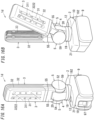
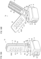
- FIG. 18A is a perspective view illustrating a lighting apparatus 1f according to a fifth variation of the first embodiment.
- FIG. 18B is a perspective view illustrating an exemplary use of the lighting apparatus 1f of the fifth variation.
- components similar to those of the lighting apparatus 1e according to the fourth variation of the first embodiment are denoted by the same reference signs as those in the first embodiment, and the description thereof is omitted.
- the lighting apparatus 1f of the fifth variation is different from the lighting apparatus 1e of the fourth variation in that the handle 14, the grip 15, and the hook 18 (see FIG. 13 ) of the lighting apparatus 1e (see FIG. 17 ) of the fourth variation are not provided.
- the lighting apparatus 1f of the fifth variation enables downsizing and cost reduction as compared to the lighting apparatus 1e of the fourth variation.
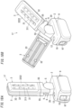
- FIG. 19A is a perspective view illustrating a lighting apparatus 1g according to a sixth variation of the first embodiment.
- FIG. 19B is a perspective view illustrating an exemplary use of the lighting apparatus 1g of the sixth variation.
- components similar to those of the lighting apparatus 1a in the first embodiment are denoted by the same reference signs as those in the first embodiment, and the description thereof is omitted.
- the plurality of light source units 3 includes two light source units 3.
- a coupling device 4 is defined such that first axes 50 (see FIG. 4 ) each corresponding to an associated one of the two light source units 3 are parallel to each other.
- designing of the coupling device 4 is facilitated.
- two hinge devices 5g corresponding to the two light source units 3 on a one-to-one basis are laterally arranged.
- the lighting apparatus 1g of the sixth variation includes two shaft bodies 7 (see FIG. 4 ) defining the first axes 50 (see FIG. 4 ).
- Each hinge device 5g couples a corresponding one of the light source units 3 to a base 2 such that the corresponding one of the light source units 3 is rotatable between a first position and a second position around the first axis 50.
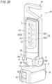
- FIG. 20 is a perspective view illustrating a lighting apparatus 1h according to a seventh variation of the first embodiment.
- the lighting apparatus 1h of the seventh variation components similar to those of the lighting apparatus 1a in the first embodiment are denoted by the same reference signs as those in the first embodiment, and the description thereof is omitted.
- the lighting apparatus 1h of the seventh variation is different from the lighting apparatus 1a of the first embodiment in that each of two light source units 3 has a semi-cylindrical shape and a light-outgoing surface 3222 is a semi-cylindrical surface.
- FIG. 21A is a perspective view illustrating a lighting apparatus 1i according to an eighth variation of the first embodiment.
- FIG. 21B is a perspective view illustrating an exemplary use of the lighting apparatus 1i of eighth variation.
- components similar to those of the lighting apparatus 1h according to the seventh variation of the first embodiment are denoted by the same reference signs as those in the first embodiment, and the description thereof is omitted.
- the lighting apparatus 1i of the eighth variation is different from the lighting apparatus 1h of the seventh variation in that the handle 14, the grip 15, and the hook 18 (see FIG. 13 ) of the lighting apparatus 1h (see FIG. 20 ) of the seventh variation are not provided.
- the lighting apparatus 1i of the eighth variation enables downsizing and cost reduction as compared to the lighting apparatus 1h of the seventh variation.
- a lighting apparatus 1j of the present embodiment will be described below with reference to FIGS. 22 and 23 .
- a basic configuration of the lighting apparatus 1j of the present embodiment is substantially the same as that of the lighting apparatus 1a in the first embodiment.
- the lighting apparatus 1j of the present embodiment is smaller than the lighting apparatus 1a of the first embodiment.
- components similar to those of the lighting apparatus 1a in the first embodiment are denoted by the same reference signs as those in the first embodiment, and the description thereof is omitted.
- the lighting apparatus 1j of the present embodiment includes a base 2j, a plurality of (two) light source units 3j, a coupling device 4j, a power supply unit (not shown), a battery pack 9j, and an attachment part 10j instead of the base 2, the plurality of (two) light source units 3, the coupling device 4, the power supply unit 8, the battery pack 9, and the attachment part 10 of the lighting apparatus 1a in the first embodiment.
- the lighting apparatus 1j of the present embodiment is smaller than the lighting apparatus 1a of the first embodiment as described above and is not provided with the handle 14, the grip 15, and the hook 18 in the lighting apparatus 1a of the first embodiment.
- the lighting apparatus 1j of the present embodiment further includes a magnet 13 provided to the base 2j, and at least one surface 13a of the magnet 13 is exposed.
- the lighting apparatus 1j of the present embodiment is fixable to, for example, a structure formed from a magnetic material (e.g., a desk made of steel).
- the lighting apparatus 1j of the present embodiment includes, similarly to the hinge device 5 of the lighting apparatus 1a in the first embodiment, hinge devices 5j coupling the light source units 3j to the base 2j such that the light source units 3j are rotatable around first axes 50.
- Each of the light source units 3j is rotatable between the first position and the second position around a corresponding first axis 50 of the first axes 50 (see FIG.
- the coupling device 4j includes a holder 20j similar to the holder 20 of the coupling device 4 of the lighting apparatus 1a in the first embodiment.
- the coupling device 4j further includes a rotation mechanism similar to the rotation mechanism 6 of the coupling device 4 of the lighting apparatus 1a in the first embodiment.
- the lighting apparatus 1j of the present embodiment further includes a hook 16 pivotably held by the base 2j.
- the hook 16 is made of metal.
- the hook 16 includes a pair of hook bodies 160 having a J-shape, a first coupler 161 which is linear and which couples base ends of the pair of hook bodies 160 to each other, and a second coupler 162 which has an arc shape and which couples tips of the pair of hook bodies 160.
- the first coupler 161 of the hooks 16 is held by the base 2j.
- the shape, size, etc. of the battery pack 9j is different from those of the battery pack 9 (see FIG. 6 ).
- the battery pack 9j includes two lithium ion batteries, a housing body 910 in which the two lithium ion batteries are accommodated, and an outer cover 920 which is tubular, which surrounds the housing body 910 at one end in a longitudinal direction of the housing body 910, and which is away from the housing body 910.
- the battery pack 9j includes a pair of manipulation pieces 925 formed on the outer cover 920. Each of the pair of manipulation pieces 925 is part of the outer cover 920.
- the battery pack 9j has slits 926 on both sides of each of the pair of manipulation pieces 925 in a circumferential direction of the outer cover 920. Thus, each of the pair of manipulation pieces 925 can be warped in a thickness direction thereof.
- the battery pack 9j has a pair of hooks 927 each protruding from a tip of a corresponding one of the pair of manipulation pieces 925.
- the battery pack 9j includes the two lithium ion batteries connected to each other in series in the housing body 910.
- the rated voltage of the battery pack 9j is 7.2 V.
- a lithium ion battery pack EZ9L21 (item number) manufactured by Panasonic Corporation may be adopted.
- the battery pack 9j provided to the base 2j is detachably attached to the attachment part 10j.
- the base 2j accommodates a power supply unit (not shown) which lights, with the battery pack 9j as a power supply, the plurality of light source units 3j.
- the attachment part 10j has a recess 100j which accommodates an insertion section 930 of the housing body 910 of the battery pack 9j.
- the insertion section 930 is not surrounded by the outer cover 920.
- the attachment part 10j has a pair of grooves 175 formed in an inner peripheral surface of the recess 100j. Each of the pair of hooks 927 is engaged with a corresponding one of the pair of grooves 175.
- the insertion section 930 of the battery pack 9j is simply inserted into the attachment part 10j to attach the battery pack 9j to the attachment part 10j.
- a pair of power supply terminals (not shown) of the battery pack 9j is electrically connected to a pair of connection terminals (not shown) of the attachment part 10j on a one-to-one basis, and the pair of hooks 927 is engaged with the pair of grooves 175 in the attachment part 10j on a one-to-one basis.
- the pair of manipulation pieces 925 are pushed in a direction in which the pair of manipulation pieces 925 approach each other to release a state where each of the pair of hooks 927 is engaged with a corresponding one of the pair of grooves 175, and the battery pack 9j is then pulled out of the attachment part 10j.
- each of the plurality of light source units 3 is rotatable around the first axis 50 and around the second axis 60 (see FIG 4 ) similarly to the lighting apparatus 1a of the first embodiment.
- circuit boards are not limited to printed wiring boards but may be molded interconnect devices (MID) or the like.
- MID molded interconnect devices
- Each of the lighting apparatus 1a to 1i includes the battery pack 9 and the attachment part 10 but is not limited to this embodiment, and in some non claimed embodiments, the battery pack 9 and the attachment part 10 do not have to be provided.
- the lighting apparatus 1j includes the battery pack 9j and the attachment part 10j but is not limited to this embodiment, and in some non claimed embodiments, the battery pack 9j and the attachment part 10j do not have to be provided.
- the lighting apparatus 1a to 1i may be configured to receive electric power supplied from an external power supply such as a commercial power supply to light the light source unit 3.
- the lighting apparatus 1a to 1i preferably includes, for example, a power supply cord for receiving the electric power supplied from the external power supply.
- the lighting apparatus 1a may include a lock mechanism for restricting the rotation of at least one of the hinge device 5 and the handle 14.
- the lock mechanism includes push buttons provided on both ends thereof in the axial direction of, for example, the first axis 50 and is configured to be switched between a locked state and an unlocked state each time the push button is manipulated.
- the lighting apparatus 1b to 1j may have similar lock mechanisms.
- Each of the lighting apparatuses 1a to 1i includes two light source units 3, but the number of the light source units 3 is not limited to two. Three or more light source units 3 may be provided.
- the lighting apparatus 1j includes two light source units 3j, but the number of the light source units 3j is not limited to two. Three or more light source units 3j may be provided.
Description
- The present invention generally relates to lighting apparatuses and specifically, to a lighting apparatus configured to change light distribution.
- As a lighting apparatus, a lighting device including a body, an illumination section, and a battery pack has been proposed in
JP 2016-51598 A - The illumination section is swingable to the body and foldable to the body via a coupler formed at the one end in the longitudinal direction of the body.
- In the field of the lighting apparatus, it may be desirable to realize various light distributions.
-
US 2013/335996 A1 describes a portable illumination device having two directable light sources each having rotational and planar (i.e., pivotal) movement capabilities. Each light source is housed in an enclosed housing assembly attached at one end to a power source enclosed in a handle casing for providing power to the light sources, a switch mechanism enabling a user to selectively actuate or deactuate one and/or both light source arrays, a magnet base capable of being mounted on a metal platform, and multiple hooks for suspension. -
JP H03 22301 A -
US D 695,434 S -
DE 20 2015 004 905 U1JP 2016-51598 A -
WO 01/01039 A1 -
JP 2007 311055 A - It has also been known to use a battery pack in a lamp, see
e.g. EP 2 056 652 A1 ,DE 296 08 888 U1 ,CN 201 155 699 YKR 101 266 419 B1 - It is an object of the present invention to provide a lighting apparatus configured to realize various light distributions. This object is achieved by a lighting apparatus as defined in
claim 1. Preferred embodiments are set forth in the dependent claims. -
-
FIG. 1 is a perspective view illustrating a lighting apparatus according to a first embodiment of the present invention; -
FIG. 2A is a front view illustrating the lighting apparatus,FIG. 2B is a left side view illustrating the lighting apparatus, andFIG. 2C is a right side view illustrating the lighting apparatus; -
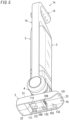
FIG. 3 is a perspective view illustrating the lighting apparatus with a handle being detached; -
FIG. 4 is an exploded perspective view illustrating the lighting apparatus; -
FIG. 5 is a perspective view illustrating the lighting apparatus with a battery pack being detached; -
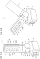
FIG. 6 is a perspective view illustrating the battery pack of the lighting apparatus; -
FIG. 7 is a view illustrating a first position and a second position of each of a plurality of light source units of the lighting apparatus; -
FIG. 8 is a perspective view illustrating an exemplary use of the lighting apparatus; -
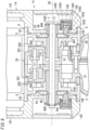
FIG. 9 is a sectional view illustrating the lighting apparatus taken along line X1-X1 ofFIG. 2A ; -
FIG. 10 is a sectional view illustrating the lighting apparatus taken along line X2-X2 ofFIG. 2A ; -
FIG. 11 is a perspective view illustrating a main part of a rotation mechanism of the lighting apparatus; -
FIG. 12 is a bottom view illustrating the light source unit of the lighting apparatus; -
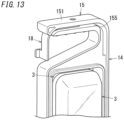
FIG. 13 is a perspective view illustrating a main part of the lighting apparatus with a hook being rotated; -
FIG 14A is a perspective view illustrating a lighting apparatus according to a first variation of the first embodiment of the present invention, andFIG. 14B is a perspective view illustrating an exemplary use of the lighting apparatus according to the first variation; -
FIG. 15 is a perspective view illustrating a lighting apparatus according to a second variation of the first embodiment of the present invention; -
FIG. 16A is a perspective view illustrating a lighting apparatus according to a third variation of the first embodiment of the present invention, andFIG. 16B is a perspective view illustrating an exemplary use of the lighting apparatus according to the third variation; -
FIG. 17 is a perspective view illustrating a lighting apparatus according to a fourth variation of the first embodiment of the present invention; -
FIG. 18A is a perspective view illustrating a lighting apparatus according to a fifth variation of the first embodiment of the present invention, andFIG. 18B is a perspective view illustrating an exemplary use of the lighting apparatus according to the fifth variation; -
FIG. 19A is a perspective view illustrating a lighting apparatus according to a sixth variation of the first embodiment of the present invention,FIG. 19B is a perspective view illustrating an exemplary use of the lighting apparatus according to the sixth variation; -
FIG. 20 is a perspective view illustrating a lighting apparatus according to a seventh variation of the first embodiment of the present invention; -
FIG. 21A is a perspective view illustrating a lighting apparatus according to an eighth variation of the first embodiment of the present invention,FIG. 21B is a perspective view illustrating an exemplary use of the lighting apparatus according to the eighth variation; -
FIG. 22 is a perspective view illustrating a lighting apparatus according to a second embodiment of the present invention with a battery pack being detached; and -
FIG. 23A is a front view illustrating the lighting apparatus according to the second embodiment,FIG. 23B is a left side view illustrating the lighting apparatus according to the second embodiment,FIG. 23C is a right side view illustrating the lighting apparatus according to the second embodiment, andFIG. 23D is a bottom view illustrating the lighting apparatus according to the second embodiment. - With reference to
FIGS. 1 to 13 , alighting apparatus 1a of the present embodiment will be described below. - The
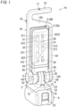
lighting apparatus 1a is a portable lighting apparatus and specifically, a lantern. Thelighting apparatus 1a is also usable as a floodlight or the like. - The
lighting apparatus 1a includes abase 2, a plurality of (in this embodiment, two)light source units 3, and acoupling device 4. Thecoupling device 4 couples the plurality oflight source units 3 to thebase 2. Thelighting apparatus 1a further includes a power supply unit 8 (seeFIG. 4 ) which lights the plurality oflight source units 3. In this embodiment, thelighting apparatus 1a further includes abattery pack 9 which supplies power to thepower supply unit 8. Thebattery pack 9 is attached to anattachment part 10 provided to thebase 2 so as to be electrically connected to thepower supply unit 8. Thelighting apparatus 1a further includes ahandle 14. Thelighting apparatus 1a further includes agrip 15. Thus, a person may hold thegrip 15, for example, when transporting thelighting apparatus 1a. - The battery pack 9 (see
FIG. 6 ) includes a plurality of (e.g., five) secondary batteries (e.g., lithium ion batteries), ahousing body 91 shaped like a rectangular parallelepiped, and aprojection base section 92 shaped like a flat rectangular parallelepiped. Thehousing body 91 accommodates the plurality of secondary batteries. Theprojection base section 92 is a part protruding from onesurface 911 of thehousing body 91. Thehousing body 91 and theprojection base section 92 are electrically insulative. In thebattery pack 9, the five lithium ion batteries are connected to each other in series in thehousing body 91. The rated voltage of thebattery pack 9 is 18 V. Thebattery pack 9 includes acommunication connector 99. Thecommunication connector 99 is a connector for communication of battery information denoting information on thebattery pack 9. The battery information includes temperature information, residual capacity information, rated voltage information, rated capacity information, count information, and the like. As thebattery pack 9, for example, a lithium ion battery pack EZ9L54 (item number) which is manufactured by Panasonic Corporation may be adopted. - The
projection base section 92 includes afirst end 921 and asecond end 922 in a longitudinal direction of the projection base section. Thebattery pack 9 has threeinsertion grooves first end 921 of theprojection base section 92. The threeinsertion grooves female connection terminals battery pack 9 includes threehooks projection base section 92. Thebattery pack 9 further includes alock section 95 exposed on the onesurface 911 of thehousing body 91 and disposed between thehook 942 and thehook 943. Thelock section 95 is inserted through ahole 915 in a wall including the onesurface 911 of thehousing body 91. Thelock section 95 receives, from a return spring accommodated in thehousing body 91, force in a direction in which thelock section 95 protrudes from the onesurface 911 of thehousing body 91. In this embodiment, the return spring is a compression coil spring. Thebattery pack 9 further includes an unlock manipulation section 97 (seeFIGS. 1 and4 ) configured to release a locked state by thelock section 95. - The
battery pack 9 is detachably attached to the attachment part 10 (seeFIGS. 1 and5 ) provided to thebase 2. - The
base 2 is shaped like a flat rectangular parallelepiped and has afirst surface 21 and a second surface 22 (seeFIG. 5 ) in a thickness direction thereof. Thebase 2 is electrically insulative. Thebase 2 is hollow and is configured to accommodate thepower supply unit 8. - As illustrated in
FIG. 5 , theattachment part 10 has arecess 100 formed in the second surface 22 of thebase 2 and accommodating theprojection base section 92 of the battery pack 9 (seeFIG. 6 ). Therecess 100 is open at the second surface 22 of thebase 2 and at oneside surface 23 in a longitudinal direction of thebase 2. Theattachment part 10 has threehooks recess 100, and which are respectively engaged with thehooks battery pack 9. Theattachment part 10 further includes acommunication connector 109 and twopower supply terminals communication connector 109 is connectable to thecommunication connector 99 of thebattery pack 9. The twopower supply terminals connection terminals connection terminals battery pack 9. In this embodiment, theconnection terminal 961 is a power supply terminal of a positive electrode of thebattery pack 9. Theconnection terminal 962 is a power supply terminal of a negative electrode of thebattery pack 9. - To attach the
battery pack 9 to theattachment part 10, for example, theprojection base section 92 of thebattery pack 9 is inserted into therecess 100 in theattachment part 10 from the second surface 22 of thebase 2 so that thehooks battery pack 9 do not interfere with thehooks attachment part 10. Then, thebattery pack 9 is shifted toward thefirst end 921 of theprojection base section 92, thereby allowing thebattery pack 9 to be attached to theattachment part 10. When thebattery pack 9 is attached to theattachment part 10, thehooks battery pack 9 are respectively engaged with thehooks attachment part 10. Moreover, a locked state where thelock section 95 of thebattery pack 9 locks thehook 133 of theattachment part 10 is achieved, wherein thehook 133 is engaged with thehook 943 of thebattery pack 9. - To detach the
battery pack 9 from theattachment part 10, for example, theunlock manipulation section 97 provided to thebattery pack 9 is manipulated to move thelock section 95 disposed between thehook 942 and thehook 943 against the spring force of the return spring and to shift thebattery pack 9 in a direction of thesecond end 922 of theprojection base section 92, and then, thebattery pack 9 is moved in a direction to be away from aninner bottom surface 101 of therecess 100 in theattachment part 10. - In the
lighting apparatus 1a, the power supply unit 8 (seeFIG. 4 ) is accommodated in thebase 2. Thepower supply unit 8 is configured to be supplied with power from thebattery pack 9 attached to theattachment part 10 so as to light thelight sources 30 of the plurality oflight source units 3. Thepower supply unit 8 generates, from direct-current power supplied from thebattery pack 9, direct-current power for lighting thelight sources 30 of the plurality oflight source units 3. More specifically, thepower supply unit 8 includes a step-up circuit configured to step up a direct-current voltage supplied from thebattery pack 9. The step-up circuit includes a control circuit. The control circuit includes a microcontroller. The microcontroller is configured as a 1-chip device including a processor configured to operate in accordance with a program, memory for storing the program for operating the processor, and work memory. The control circuit is realizable by causing the microcontroller to execute the program. Thepower supply unit 8 includes a plurality of circuit elements 81 (an inductor, a switching element, a diode, a capacitor, a microcontroller, and the like) of the step-up circuit and acircuit board 82 on which the plurality ofcircuit elements 81 are mounted. The control circuit performs ON/OFF control of the switching element. On thecircuit board 82 of thepower supply unit 8, the pair ofpower supply terminals communication connector 109 of theattachment part 10 are also mounted. - The
lighting apparatus 1a includes a manipulation switch 12 (seeFIGS. 1 and4 ) for an instruction of full lighting (rated lighting), dimming lighting, and non-lighting of thelight source unit 3. In thelighting apparatus 1a, the control circuit of thepower supply unit 8 acquires a manipulation signal when themanipulation switch 12 is manipulated. As used herein, "the control circuit acquires a manipulation signal" may mean that the control circuit detects that themanipulation switch 12 is manipulated. Thepower supply unit 8 may be configured to switch the plurality oflight source units 3 to a full lighting state, a dimming lighting state, and a non-lighting state sequentially each time themanipulation switch 12 is manipulated. Themanipulation switch 12 is a push button switch. Themanipulation switch 12 is mounted on thecircuit board 82 of thepower supply unit 8 and is connected to the control circuit of thepower supply unit 8. Thebase 2 has a hole 211 (seeFIG. 4 ) through which apush button 121 of themanipulation switch 12 is exposed on thefirst surface 21 of thebase 2. - The
power supply unit 8 includes aconnector 84 to which a lead wire 39 (seeFIGS. 4 and12 ) for connecting thepower supply unit 8 to thelight source unit 3 is connected. Theconnector 84 is mounted on thecircuit board 82. - Each
light source unit 3 includes alight source 30 and acase 32. Thelight source 30 is accommodated in thecase 32. Thelight source 30 includes two light emitting diode (LED)modules 31. Each of the twoLED modules 31 includes anLED 311 and acircuit board 312 on which theLED 311 is mounted. Moreover, each of the twoLED modules 31 further includes a connector 34 (seeFIG. 1 ) to which thelead wire 39 for connecting thelight source unit 3 to thepower supply unit 8 is connected. - Each
LED 311 is, for example, a surface-mounted LED. The light source color of eachLED 311 is preferably set based on a correlated color temperature of a light source color of an LED defined in accordance with, for example, JIS Z9112:2012. The light source color of theLED 311 is neutral white but is not limited to this example and may be, for example, an incandescent color. - Each
circuit board 312 is, for example, a printed wiring board. Preferably, the printed wiring board is highly thermally conductive. The printed wiring board is formed of, for example, a woven/non-woven glass cloth composite base material epoxy resin copper clad laminated board satisfying the specification of the composite epoxy materials-3 (CEM-3). - Each
LED module 31 preferably includes a plurality of (e.g., five)LEDs 311. In theLED module 31, thecircuit board 312 has an elongated flat plate shape. In theLED module 31, the fiveLEDs 311 are arranged on thecircuit board 312 to be aligned in a low along a longitudinal direction of thecircuit board 312, and the fiveLEDs 311 are connected to each other in series. In theLED module 31, the fiveLEDs 311 are arranged at substantially the same intervals. The expression "substantially the same intervals" mentioned herein does not mean the same intervals in a strict sense, but intervals within a prescribed range are allowable. - In each of the plurality of
light source units 3, the twocircuit boards 312 are tilted in different directions to a flat surface orthogonal to a thickness direction of thelight source unit 3 so as to increase the angle of light distribution as compared to a case where the twocircuit boards 312 are arranged parallel to each other on one flat surface. Thus, each of the plurality oflight source units 3 is disposed in thecase 32 such that optical axes of theLEDs 311 of the twoLED modules 31 are oriented in different directions. - Each
LED module 31 may include, in thecase 32, a reflector which reflects light from thelight source 30 to a light-outgoingsurface 3222. - The
case 32 has a panel shape. The outer peripheral shape of thecase 32 seen in a thickness direction of thecase 32 is rectangular. Thecase 32 includes abody 321 holding thelight source 30 and acover 322. Thebody 321 holds thelight source 30. Thecover 322 is coupled to thebody 321 to cover thelight source 30 and has a surface at least part of which is included in the light-outgoingsurface 3222. Thebody 321 is made of an ABS resin. Thecover 322 is made of polycarbonate. In the case of thelight source unit 3, light radiated from thelight source 30 is emitted from the light-outgoingsurface 3222. - The
light source unit 3 further includes a projection 33 (seeFIG. 4 ) protruding from a rear surface 3212 (seeFIG. 4 ) on an opposite side of thecase 32 from the light-outgoingsurface 3222. This enables thelighting apparatus 1a to increase a heat dissipation area as compared to a case where theprojection 33 is not provided on therear surface 3212 and to improve heat dissipation characteristics. Thelight source unit 3 preferably includes a plurality ofprojections 33. This enables thelighting apparatus 1a to further improve the heat dissipation characteristics. According to thelight source unit 3, the plurality ofprojections 33 are provided along a longitudinal direction of thecase 32. - The
lighting apparatus 1a includes acoupling device 4 coupling the plurality of (two)light source units 3 to thebase 2. Thecoupling device 4 is configured to enable each of the plurality oflight source units 3 to rotate around a corresponding one of first axes 50 (seeFIG. 4 ) and around a corresponding one of second axes 60 (seeFIG. 4 ) transverse to the first axes 50. Thecoupling device 4 includes a shaft body 7 (seeFIGS. 3 ,4 ,9 , and10 ), aholder 20, a plurality of (two)hinge devices 5, and a plurality of (two) rotation mechanisms 6 (seeFIGS. 4 and11 ). - As illustrated in
FIGS. 4 and9 , in thelighting apparatus 1a, theshaft body 7 defines the first axes 50. In other words, in thelighting apparatus 1a, the axis line of theshaft body 7 forms the first axes 50. Theshaft body 7 includes ashaft 71. Theshaft body 7 is held by theholder 20. Theholder 20 has a hollow columnar shape. Theholder 20 protrudes from thefirst surface 21 of thebase 2. In this embodiment, theholder 20 is formed integrally with thebase 2. Theholder 20 is disposed such that the axial direction thereof is a direction along a short direction of thebase 2. Theholder 20 includes a shaft section 201 (seeFIGS. 4 and9 ) provided at each of both ends in the axial direction of the holder and having a smaller outer diameter than a part between the both ends of theholder 20. Theshaft body 7 is inserted through ahole 204 in each of the pair ofshaft sections 201 of the holder 20 (seeFIGS. 4 and9 ). - Each
hinge device 5 couples thelight source unit 3 to thebase 2 such that thelight source unit 3 is rotatable between a first position (hereinafter also referred to as a "reference position") and a second position (hereinafter also referred to as a "spread position") around thefirst axis 50. The reference position is a position at which a tip of each one of the plurality oflight source units 3 is located closest to a tip of the otherlight source unit 3. The spread position is a position at which each of the plurality oflight source units 3 arrives after the largest angle of rotation from the reference position. - Each
hinge device 5 includes abearing 51, aring section 52, acoupler 53, ahinge section 54, and anarm 55. - The
bearing 51 has a cylindrical shape. Thebearing 51 is rotatably supported by theshaft body 7. - The
ring section 52 surrounds thebearing 51 and is concentric with thebearing 51. The inner diameter of thering section 52 is larger than the outer diameter of thebearing 51. Thering section 52 is away from the bearing 51 in the radial direction of thering section 52. - The
coupler 53 is disposed between the bearing 51 and thering section 52 and couples the bearing 51 to thering section 52. - The
hinge section 54 is rotatably held by oneshaft section 201 of the twoshaft sections 201 of theholder 20 which is located away from thebearing 51. Theshaft section 201 is concentric with thering section 52. - The
arm 55 couples thering section 52 to thehinge section 54. Thearm 55 protrudes radially outward from each of thering section 52 and thehinge section 54. Thearm 55 rotates together with thering section 52 and thehinge section 54. In thelighting apparatus 1a, thelight source unit 3 is coupled to thearm 55. - Moreover, as illustrated in
FIGS. 4 and10 , eachhinge device 5 preferably further includes aclick plate 56, aclick member 57, and areturn spring 58. - The
click plate 56 has an arc shape, is laid on thecoupler 53, and is fixed to thecoupler 53. Theclick plate 56 has a counter surface which faces theshaft section 201 of theholder 20 and in which a plurality ofrecesses 561 each having a hemispherical shape are formed. The plurality ofrecesses 561 have the same size. The plurality ofrecesses 561 are arranged in the circumferential direction of theclick plate 56 at substantially the same intervals. The plurality ofrecesses 561 are arranged such that thearm 55 is rotatable around thefirst axis 50 within a first specified range of angles (e.g., 90 degrees). - As illustrated in
FIG. 10 , theclick member 57 includes a base 571 having a columnar shape and aclick projection 572. Thebase 571 is arranged in theholder 20. Theclick projection 572 protrudes from theshaft section 201 through ahole 203. Thehole 203 has a round shape and is formed in atip wall 202 of theshaft section 201. The base 571 integrally includes aflange 573 having an outer diameter larger than the inner diameter of thehole 203. Thebase 571 is disposed in theholder 20 such that the axial direction thereof is parallel to the first axis 50 (seeFIGS. 4 and9 ). Theclick projection 572 has a hemispherical shape. Theclick projection 572 is removable from and insertable into each of the plurality of recesses 561 (seeFIGS. 4 and10 ) in theclick plate 56. Thereturn spring 58 is a coil spring. Thereturn spring 58 applies, to theflange 573 of theclick member 57, force in a direction in which theclick projection 572 protrudes from theshaft section 201. Thus, theclick projection 572 is movable between a position at which theclick projection 572 protrudes from theshaft section 201 and a position at which theclick projection 572 does not protrude from theshaft section 201. In thelighting apparatus 1a, when a user rotates thelight source units 3 around thefirst axes 50, the positions of thelight source units 3 are easily maintained at desired rotational positions. Moreover, in thelighting apparatus 1a, it is possible for a user to perceive click feeling when the user rotates thelight source units 3. - The
lighting apparatus 1a includes the plurality ofhinge devices 5, and the plurality ofhinge devices 5 are configured such that when the plurality oflight source units 3 rotate from the reference position to the spread position, rotation directions of the plurality oflight source units 3 are different. More specifically, in thelighting apparatus 1a, the twohinge devices 5 are arranged such that the click plates 56 (seeFIG. 4 ) do not overlap each other in the direction of the first axes 50 (seeFIG. 4 ). In the following description, for convenience of explanation, onelight source unit 3 of the twolight source units 3 may be referred to as alight source unit 3A, and the otherlight source unit 3 of the twolight source units 3 may be referred to as alight source unit 3B. In the example shown inFIG. 7 , thelight source unit 3A is in the reference position of thelight source unit 3A, and thelight source unit 3B is in the reference position of thelight source unit 3B. Moreover, inFIG. 7 , thelight source unit 3A rotated to the spread position of thelight source unit 3A is shown by the long dashed double-short dashed line, and thelight source unit 3B rotated to the spread position of thelight source unit 3B is shown by the long dashed double-short dashed line. The angle of rotation of eachlight source unit 3 around thefirst axis 50 from the reference position to the spread position by thehinge device 5 is substantially 90 degrees. - As illustrated in
FIG. 4 , eachrotation mechanism 6 couples thelight source unit 3 to thehinge device 5 such that thelight source unit 3 is rotatable around thesecond axis 60 transverse to thefirst axis 50. - As illustrated in
FIGS. 4 ,11 , and12 , eachrotation mechanism 6 includes ashaft section 61 and abearing 62. Theshaft section 61 is coupled to thelight source unit 3 at one end in a longitudinal direction of thelight source unit 3. Theshaft section 61 protrudes from acounter surface 35 of thelight source unit 3, thecounter surface 35 facing thearm 55 of thehinge device 5. Theshaft section 61 has a cylindrical shape. Thelead wire 39, which electrically connects thelight source unit 3 topower supply unit 8, is inserted through theshaft section 61. Thebearing 62 is provided to thearm 55 and freely rotatably holds theshaft section 61. In thelighting apparatus 1a, thebearing 62 defines thesecond axis 60. - In each
rotation mechanism 6, theshaft section 61 is coupled to thearm 55 so as to be rotatable around thesecond axis 60 within a specified range of angles (e.g., 330 degrees) smaller than 360 degrees. The angle of rotation of thelight source unit 3 around thesecond axis 60 by therotation mechanism 6 is substantially 330 degrees. - The plurality of
rotation mechanisms 6 define rotation ranges of the plurality oflight source units 3 around thesecond axes 60 to achieve a reference state where the plurality oflight source units 3 are collected together and light-outgoingsurfaces 3222 of the plurality oflight source units 3 face outward when each of the plurality oflight source units 3 is in the reference position. The plurality oflight source units 3 are individually rotatable around thefirst axes 50 and thesecond axes 60. Note that when each of the plurality oflight source units 3 is in the reference position, each of the plurality oflight source unit 3 is rotatable around only thefirst axis 50 and is inhibited from rotating around thesecond axis 60. In a case where the plurality oflight source units 3 includes twolight source units 3 and the twolight source units 3 are in the reference position, even when one of the twolight source units 3 is attempted to be rotated aroundsecond axis 60, the presence of the otherlight source unit 3 inhibits the rotation of the onelight source unit 3. When at least onelight source unit 3 of the plurality oflight source units 3 is at a rotated position around thefirst axis 50 with respect to the reference position, each of the plurality oflight source units 3 is rotatable around thesecond axis 60. - In the
lighting apparatus 1a, thecoupling device 4 enables the light-outgoingsurfaces 3222 of the twolight source units 3 to face each other. - The
lighting apparatus 1a further includes thehandle 14 coupled to thecoupling device 4. In thelighting apparatus 1a, thehandle 14 is a component to be gripped by a hand of a user of thelighting apparatus 1a. Thehandle 14 is electrically insulative. Thehandle 14 is made of a synthetic resin (e.g., polypropylene). - As illustrated in
FIGS. 1 and4 , thehandle 14 is open toward thebase 2 and thus has a U-shape. More specifically, thehandle 14 includes a pair ofside sections 141, acenter section 142 connecting base ends of the pair ofside sections 141, and a pair ofrotors 143 each provided to a tip of a corresponding one of the pair ofside sections 141. Eachrotor 143 has a disk shape. In thelighting apparatus 1a, the pair ofrotors 143 is coupled to thecoupling device 4 such that thehandle 14 is rotatable around the first axes 50. - As shown in
FIGS. 4 and9 , each of the pair ofrotors 143 includes ashaft section 1432 rotatably held by thering section 52 of thehinge device 5, aclick member 144, and areturn spring 145. Theshaft section 1432 has atip wall 1433 in which ahole 1435 having a round shape is formed. Through thehole 1435, theshaft body 7 is inserted. In thelighting apparatus 1a, thecoupling device 4 further includes a pair ofclick plates 49 fixed to theshaft body 7. - Each
click plate 49 has a disk shape and is laid on thecoupler 53 of thehinge device 5. Theclick plate 49 has anon-circular hole 490 through which theshaft body 7 is inserted. Theclick plate 49 has a counter surface which faces theshaft section 1432 of therotor 143 and in which a plurality ofrecesses 491 having a semispherical shape are formed. The plurality ofrecesses 491 have the same size. The plurality ofrecesses 491 are disposed in the circumferential direction of theclick plate 49 at the substantially the same intervals. The plurality ofrecesses 491 are arranged such that therotor 143 is rotatable around thefirst axis 50 within a third specified range of angles (e.g., 360 degrees). - The click member 144 (see
FIG. 9 ) includes abase 1441 having a columnar shape and aclick projection 1442. Thebase 1441 is disposed in therotor 143. Theclick projection 1442 protrudes from theshaft section 1432 through ahole 1434 in thetip wall 1433 of theshaft section 1432. Thebase 1441 integrally has aflange 1443 having an outer diameter larger than the inner diameter of thehole 1434. Thebase 1441 is disposed in therotor 143 such that an axial direction thereof is parallel to thefirst axis 50. Theclick projection 1442 has a semispherical shape. Theclick projection 1442 is removable from and insertable into each of the plurality ofrecesses 491 in theclick plate 49. Thereturn spring 145 is a coil spring. Thereturn spring 145 applies, to theflange 1443 of theclick member 144, force in a direction in which theclick projection 1442 protrudes from theshaft section 1432. Thus, theclick projection 1442 is movable between a position at which theclick projection 1442 protrudes from theshaft section 1432 and a position at which theclick projection 1442 does not protrude from theshaft section 1432. In thelighting apparatus 1a, when a user rotates thehandle 14 around thefirst axes 50, the position of thehandle 14 is easily maintained at a desired rotational position. Moreover, in thelighting apparatus 1a, it is possible for a user to perceive click feeling when the user rotates thehandle 14. - As illustrated in
FIG. 1 , thelighting apparatus 1a further includes thegrip 15 which is L-shaped and which is formed integrally with thehandle 14. In thelighting apparatus 1a, thegrip 15 is a component to be held by a hand of a user of the lighting apparatus la. Thegrip 15 protrudes on an opposite side of thecenter section 142 of thehandle 14 from the pair ofside sections 141. - As illustrated in
FIGS. 2B and13 , thegrip 15 has aside surface 151 having aslit 155 which is L-shaped. In theslit 155 which is L-shaped, ahook 18 which is L-shaped is removably and insertably accommodated. In this embodiment, thehook 18 is rotatably coupled to thegrip 15 by a screw 17 (seeFIG. 1 ). - The
lighting apparatus 1a of the present embodiment described above includes thebase 2, the plurality oflight source units 3, and thecoupling device 4. Thecoupling device 4 couples the plurality oflight source units 3 to thebase 2. Thecoupling device 4 includes the plurality ofhinge devices 5 and the plurality ofrotation mechanisms 6. The plurality ofhinge devices 5 couple the plurality oflight source units 3 to thebase 2 such that the plurality oflight source units 3 are rotatable around the first axes 50. Each of the plurality oflight source units 3 is rotatable between the first position (reference position) and the second position (spread position) around a correspondingfirst axis 50 of the first axes 50. The plurality ofrotation mechanisms 6 couple the plurality oflight source units 3 to the plurality ofhinge devices 5 such that the plurality oflight source units 3 are rotatable around thesecond axes 60 transverse to the first axes 50. The plurality ofhinge devices 5 are configured such that when each of the plurality oflight source units 3 rotates from the first position to the second position, rotation directions of the plurality oflight source units 3 are different. The plurality ofrotation mechanisms 6 define rotation ranges of the plurality oflight source units 3 around thesecond axes 60 to achieve a reference state where the plurality oflight source units 3 are collected together and light-outgoingsurfaces 3222 of the plurality oflight source units 3 face outward when each of the plurality oflight source units 3 is in the first position. - This configuration enables the
lighting apparatus 1a to realize various light distributions. - In the
lighting apparatus 1a, each of the plurality ofhinge devices 5 includes thehinge section 54 having a ring shape; thering section 52, thehinge section 54 and thering section 52 being rotatable around a corresponding one of thefirst axes 50; and thearm 55 coupling thehinge section 54 to thering section 52 and protruding radially outward from thehinge section 54 and thering section 52. Each of the plurality ofrotation mechanisms 6 includes theshaft section 61 and thebearing 62. Theshaft section 61 protrudes from thecounter surface 35 of a corresponding one of the plurality oflight source units 3, thecounter surface 35 facing thearm 55. Thebearing 62 is provided to thearm 55, freely rotatably holds theshaft section 61, and defines thesecond axis 60. This allows thelighting apparatus 1a to inhibit rotation of the plurality oflight source units 3 around thesecond axes 60 when each of the plurality oflight source unit 3 is in the first position. In thelighting apparatus 1a, each of thefirst axes 50 may be orthogonal to a corresponding one of thesecond axes 60. - In the
lighting apparatus 1a, the plurality oflight source units 3 includes twolight source units 3. In thecoupling device 4 in thelighting apparatus 1a, thefirst axes 50 each corresponding to an associated one of the twolight source units 3 are coincident. Thus, in thelighting apparatus 1a, it is possible to relatively increase the size of each of the plurality ofhinge devices 5 seen in a direction along the first axes 50. This enables thelighting apparatus 1a to make a user imagine various applications for the sake of design emphasizing the plurality ofhinge devices 5. - In the
lighting apparatus 1a, each of the plurality oflight source units 3 includes thelight source 30 and thecase 32 accommodating thelight source 30. In this embodiment, thelighting apparatus 1a preferably further includes theprojection 33 protruding from therear surface 3212 on an opposite side, of thecase 32 from the light-outgoingsurface 3222. This enables thelighting apparatus 1a to improve heat dissipation characteristics. - In the
lighting apparatus 1a, thelight source 30 includes twoLED modules 31. Each of the twoLED modules 31 includes theLED 311 and thecircuit board 312 on which theLED 311 is mounted. Each of the plurality oflight source units 3 is preferably disposed in thecase 32 such that the optical axes of theLEDs 311 of the twoLED modules 31 are oriented in different directions. Thus, thelighting apparatus 1a enables a further increase in the angle of light distribution of each of the plurality oflight source units 3. Therefore, thelighting apparatus 1a enables a further increase in the angle of light distribution of thelighting apparatus 1a as a whole when each of the plurality oflight source units 3 is in the first position. In thelighting apparatus 1a of the present embodiment, the angle of light distribution can be 360 degrees. - The
lighting apparatus 1a preferably further includes theattachment part 10 and thepower supply unit 8. Theattachment part 10 is provided to thebase 2, and to theattachment part 10, thebattery pack 9 is detachably attached. Thepower supply unit 8 is accommodated in thebase 2 and is configured to light, with thebattery pack 9 as a power supply, the plurality oflight source units 3. Thus, in thelighting apparatus 1a, thepower supply unit 8 and thelight source unit 3 can be separated, and therefore, it is possible to reduce the size and the weight of thelight source unit 3 as compared to a case where thepower supply unit 8 is provided integrally with thelight source unit 3. Moreover, attaching thebattery pack 9 to theattachment part 10 allows thelighting apparatus 1a to be used in locations where no external power supply is available. - The
lighting apparatus 1a preferably further includes themanipulation switch 12 provided to thebase 2. In thelighting apparatus 1a, thepower supply unit 8 may be configured to sequentially switch the plurality oflight source units 3 to the full lighting state, the dimming lighting state, and the non-lighting state each time themanipulation switch 12 is manipulated when thebattery pack 9 is attached to theattachment part 10 and the power supply unit is supplied with power from thebattery pack 9. This enables thelighting apparatus 1a to realize various illumination scenes. - Moreover, the
lighting apparatus 1a preferably further includes thehandle 14 which is rotatable around the first axes 50. This enables thelighting apparatus 1a to realize various light distributions. Moreover, in thelighting apparatus 1a, it is possible to reduce shadows made by thehandle 14 blocking light (illumination light) emitted from the light-outgoingsurface 3222 of thelight source unit 3. - In the
lighting apparatus 1a, thehandle 14 includes the pair ofside sections 141, thecenter section 142 connecting the base ends of the pair ofside sections 141, and the pair ofrotors 143 each provided at a corresponding one of the tips of the pair ofside sections 141. The pair ofrotors 143 is preferably coupled to thecoupling device 4 such that thehandle 14 is rotatable around the first axes 50. This enables thelighting apparatus 1a to change the angle of thehandle 14 to thelight source units 3 and thebase 2 around thefirst axes 50, thereby further improving the degree of freedom of light distribution. Moreover, in thelighting apparatus 1a, it is possible to reduce shadows made by thehandle 14 blocking light (illumination light) emitted from the light-outgoingsurface 3222 of thelight source unit 3. - The
lighting apparatus 1a may further include thegrip 15 being L-shaped and protruding on an opposite side of thecenter section 142 of thehandle 14 from the pair ofside sections 141. Providing thegrip 15 to thelighting apparatus 1a enables portability by a user to be improved. Moreover, providing thegrip 15 to thelighting apparatus 1a increases the degree of freedom of installation place, which makes it possible to realize various light distributions. - The
lighting apparatus 1a preferably further includes thehook 18 which is L-shaped and which has one end rotatably coupled to a part of thegrip 15 by thescrew 17. The part of thegrip 15 faces thecenter section 142 of thehandle 14. Thegrip 15 has theside surface 151 having theslit 155 which is L-shaped and in which thehook 18 is removably and insertably accommodated. Providing thehook 18 to thelighting apparatus 1a increases the degree of freedom of installation place, which makes it possible to realize various light distributions. Moreover, in thelighting apparatus 1a, adopting thehook 18 makes it possible to prevent thelighting apparatus 1a from falling. The providing thehook 18 enables thelighting apparatus 1a to be used by being hooked on, for example, doors, partitions, and the like of buildings (dwelling units, buildings, facilities, and the like) under construction. -
FIG. 14A is a perspective view illustrating alighting apparatus 1b according to a first variation of the first embodiment.FIG. 14B is a perspective view illustrating an exemplary use of thelighting apparatus 1b. For thelighting apparatus 1b, components similar to those of thelighting apparatus 1a in the first embodiment are denoted by the same reference signs as those in the first embodiment, and the description thereof is omitted. - The
lighting apparatus 1b of the first variation is different from thelighting apparatus 1a of the first embodiment in that thehandle 14, thegrip 15, and thehook 18 of thelighting apparatus 1a (seeFIG. 1 ) of the first embodiment are not provided. Thelighting apparatus 1b of the first variation enables downsizing and cost reduction as compared to the lighting apparatus la of the first embodiment. Thelighting apparatus 1b includes a disk-shapedlid 59 closing an opening in aring section 52 of ahinge device 5 instead of therotor 143 of thehandle 14. This enables thelighting apparatus 1b of the first variation to reduce dust or the like externally entering through the opening in thering section 52. -
FIG. 15 is a perspective view illustrating alighting apparatus 1c according to a second variation of the first embodiment. For thelighting apparatus 1c of the second variation, components similar to those of thelighting apparatus 1a in the first embodiment are denoted by the same reference signs as those in the first embodiment, and the description thereof is omitted. - The
lighting apparatus 1c of the second variation is different from thelighting apparatus 1a of the first embodiment in that acoupling device 4 further includes arotation mechanism 19 rotatable around a third axis transverse tofirst axes 50 with respect to abase 2. This enables thelighting apparatus 1c of the second variation to realize various light distributions as compared to thelighting apparatus 1a of the first embodiment. - The
coupling device 4 in thelighting apparatus 1c of the second variation includes the rotation mechanism 19 (second rotation mechanism) in addition to the plurality of rotation mechanism 6 (first rotation mechanism) of thelighting apparatus 1a (seeFIG. 4 ) of the first embodiment. - The
rotation mechanism 19 includes a shaft section (not shown) and abearing 192. The shaft section (not shown) is provided to, for example, aholder 20, is separate from a shaft section 201 (seeFIG. 4 ), and protrudes from theholder 20 toward thebase 2. Thebearing 192 is provided to thebase 2 and rotatably holds the shaft section. In thelighting apparatus 1c of the second variation, the bearing 192 provided to thebase 2 defines the third axis. The third axis is orthogonal to the first axes 50 (seeFIG. 4 ) and is orthogonal to afirst surface 21 of thebase 2. In sum, the third axis is orthogonal to thefirst axes 50 and is parallel to the upward and downward direction inFIG. 15 . -
FIG. 16A is a perspective view illustrating alighting apparatus 1d according to a third variation of the first embodiment.FIG. 16B is a perspective view illustrating an exemplary use of thelighting apparatus 1d of the third variation. For thelighting apparatus 1d of the third variation, components similar to those of thelighting apparatus 1c according to the second variation of the first embodiment are denoted by the same reference signs as those in the first embodiment, and the description thereof is omitted. - The
lighting apparatus 1d of the third variation is different from thelighting apparatus 1c of the second variation in that thehandle 14, thegrip 15, and the hook 18 (seeFIG. 13 ) of thelighting apparatus 1c (seeFIG. 15 ) according to the second variation of the first embodiment are not provided. Thelighting apparatus 1d of the third variation enables downsizing and cost reduction as compared to thelighting apparatus 1c of the second variation. Thelighting apparatus 1d of the third variation includes a disk-shapedlid 59 closing an opening in aring section 52 of ahinge device 5 instead of the rotor 143 (seeFIG. 15 ) of thehandle 14. This enables thelighting apparatus 1d of the third variation to reduce dust or the like externally entering through the opening in thering section 52. -
FIG. 17 is a perspective view illustrating alighting apparatus 1e according to a fourth variation of the first embodiment. For thelighting apparatus 1e of the fourth variation, components similar to those of thelighting apparatus 1a in the first embodiment are denoted by the same reference signs as those in the first embodiment, and the description thereof is omitted. - The
lighting apparatus 1e of the fourth variation is different from thelighting apparatus 1a of the first embodiment in that acoupling device 4 is configured such that when each of twolight source units 3 are in the first position (reference position), the thickness direction of eachlight source unit 3 is a direction along first axes 50 (seeFIG. 4 ). -
FIG. 18A is a perspective view illustrating alighting apparatus 1f according to a fifth variation of the first embodiment.FIG. 18B is a perspective view illustrating an exemplary use of thelighting apparatus 1f of the fifth variation. For thelighting apparatus 1f of the fifth variation, components similar to those of thelighting apparatus 1e according to the fourth variation of the first embodiment are denoted by the same reference signs as those in the first embodiment, and the description thereof is omitted. - The
lighting apparatus 1f of the fifth variation is different from thelighting apparatus 1e of the fourth variation in that thehandle 14, thegrip 15, and the hook 18 (seeFIG. 13 ) of thelighting apparatus 1e (seeFIG. 17 ) of the fourth variation are not provided. Thelighting apparatus 1f of the fifth variation enables downsizing and cost reduction as compared to thelighting apparatus 1e of the fourth variation. -
FIG. 19A is a perspective view illustrating alighting apparatus 1g according to a sixth variation of the first embodiment.FIG. 19B is a perspective view illustrating an exemplary use of thelighting apparatus 1g of the sixth variation. For thelighting apparatus 1g of the sixth variation, components similar to those of thelighting apparatus 1a in the first embodiment are denoted by the same reference signs as those in the first embodiment, and the description thereof is omitted. - In the
lighting apparatus 1g of the sixth variation, similarly to thelighting apparatus 1a of the first embodiment, the plurality oflight source units 3 includes twolight source units 3. In thelighting apparatus 1g, acoupling device 4 is defined such that first axes 50 (seeFIG. 4 ) each corresponding to an associated one of the twolight source units 3 are parallel to each other. Thus, in thelighting apparatus 1g of the sixth variation, designing of thecoupling device 4 is facilitated. In thelighting apparatus 1g of the sixth variation, twohinge devices 5g corresponding to the twolight source units 3 on a one-to-one basis are laterally arranged. In this embodiment, thelighting apparatus 1g of the sixth variation includes two shaft bodies 7 (seeFIG. 4 ) defining the first axes 50 (seeFIG. 4 ). Eachhinge device 5g couples a corresponding one of thelight source units 3 to abase 2 such that the corresponding one of thelight source units 3 is rotatable between a first position and a second position around thefirst axis 50. -
FIG. 20 is a perspective view illustrating alighting apparatus 1h according to a seventh variation of the first embodiment. For thelighting apparatus 1h of the seventh variation, components similar to those of thelighting apparatus 1a in the first embodiment are denoted by the same reference signs as those in the first embodiment, and the description thereof is omitted. - The
lighting apparatus 1h of the seventh variation is different from thelighting apparatus 1a of the first embodiment in that each of twolight source units 3 has a semi-cylindrical shape and a light-outgoingsurface 3222 is a semi-cylindrical surface. -
FIG. 21A is a perspective view illustrating alighting apparatus 1i according to an eighth variation of the first embodiment.FIG. 21B is a perspective view illustrating an exemplary use of thelighting apparatus 1i of eighth variation. For thelighting apparatus 1i of the eighth variation, components similar to those of thelighting apparatus 1h according to the seventh variation of the first embodiment are denoted by the same reference signs as those in the first embodiment, and the description thereof is omitted. - The
lighting apparatus 1i of the eighth variation is different from thelighting apparatus 1h of the seventh variation in that thehandle 14, thegrip 15, and the hook 18 (seeFIG. 13 ) of thelighting apparatus 1h (seeFIG. 20 ) of the seventh variation are not provided. Thelighting apparatus 1i of the eighth variation enables downsizing and cost reduction as compared to thelighting apparatus 1h of the seventh variation. - A
lighting apparatus 1j of the present embodiment will be described below with reference toFIGS. 22 and23 . - A basic configuration of the
lighting apparatus 1j of the present embodiment is substantially the same as that of thelighting apparatus 1a in the first embodiment. Thelighting apparatus 1j of the present embodiment is smaller than thelighting apparatus 1a of the first embodiment. For thelighting apparatus 1j of the present embodiment, components similar to those of thelighting apparatus 1a in the first embodiment are denoted by the same reference signs as those in the first embodiment, and the description thereof is omitted. - The
lighting apparatus 1j of the present embodiment includes abase 2j, a plurality of (two)light source units 3j, acoupling device 4j, a power supply unit (not shown), abattery pack 9j, and anattachment part 10j instead of thebase 2, the plurality of (two)light source units 3, thecoupling device 4, thepower supply unit 8, thebattery pack 9, and theattachment part 10 of thelighting apparatus 1a in the first embodiment. - Moreover, the
lighting apparatus 1j of the present embodiment is smaller than thelighting apparatus 1a of the first embodiment as described above and is not provided with thehandle 14, thegrip 15, and thehook 18 in thelighting apparatus 1a of the first embodiment. - On the other hand, the
lighting apparatus 1j of the present embodiment further includes amagnet 13 provided to thebase 2j, and at least onesurface 13a of themagnet 13 is exposed. Thus, thelighting apparatus 1j of the present embodiment is fixable to, for example, a structure formed from a magnetic material (e.g., a desk made of steel). Moreover, thelighting apparatus 1j of the present embodiment includes, similarly to thehinge device 5 of thelighting apparatus 1a in the first embodiment,hinge devices 5j coupling thelight source units 3j to thebase 2j such that thelight source units 3j are rotatable around first axes 50. Each of thelight source units 3j is rotatable between the first position and the second position around a correspondingfirst axis 50 of the first axes 50 (seeFIG. 4 ). Thecoupling device 4j includes aholder 20j similar to theholder 20 of thecoupling device 4 of thelighting apparatus 1a in the first embodiment. Thecoupling device 4j further includes a rotation mechanism similar to therotation mechanism 6 of thecoupling device 4 of thelighting apparatus 1a in the first embodiment. - The
lighting apparatus 1j of the present embodiment further includes ahook 16 pivotably held by thebase 2j. Thehook 16 is made of metal. Thehook 16 includes a pair ofhook bodies 160 having a J-shape, afirst coupler 161 which is linear and which couples base ends of the pair ofhook bodies 160 to each other, and asecond coupler 162 which has an arc shape and which couples tips of the pair ofhook bodies 160. Thefirst coupler 161 of thehooks 16 is held by thebase 2j. - The shape, size, etc. of the
battery pack 9j is different from those of the battery pack 9 (seeFIG. 6 ). Thebattery pack 9j includes two lithium ion batteries, ahousing body 910 in which the two lithium ion batteries are accommodated, and anouter cover 920 which is tubular, which surrounds thehousing body 910 at one end in a longitudinal direction of thehousing body 910, and which is away from thehousing body 910. Thebattery pack 9j includes a pair ofmanipulation pieces 925 formed on theouter cover 920. Each of the pair ofmanipulation pieces 925 is part of theouter cover 920. Thebattery pack 9j hasslits 926 on both sides of each of the pair ofmanipulation pieces 925 in a circumferential direction of theouter cover 920. Thus, each of the pair ofmanipulation pieces 925 can be warped in a thickness direction thereof. Moreover, thebattery pack 9j has a pair ofhooks 927 each protruding from a tip of a corresponding one of the pair ofmanipulation pieces 925. - The
battery pack 9j includes the two lithium ion batteries connected to each other in series in thehousing body 910. The rated voltage of thebattery pack 9j is 7.2 V. As thebattery pack 9j, for example, a lithium ion battery pack EZ9L21 (item number) manufactured by Panasonic Corporation may be adopted. - The
battery pack 9j provided to thebase 2j is detachably attached to theattachment part 10j. Thebase 2j accommodates a power supply unit (not shown) which lights, with thebattery pack 9j as a power supply, the plurality oflight source units 3j. - The
attachment part 10j has arecess 100j which accommodates aninsertion section 930 of thehousing body 910 of thebattery pack 9j. Theinsertion section 930 is not surrounded by theouter cover 920. - The
attachment part 10j has a pair ofgrooves 175 formed in an inner peripheral surface of therecess 100j. Each of the pair ofhooks 927 is engaged with a corresponding one of the pair ofgrooves 175. - In the
lighting apparatus 1j of the present embodiment, theinsertion section 930 of thebattery pack 9j is simply inserted into theattachment part 10j to attach thebattery pack 9j to theattachment part 10j. Thus, in thelighting apparatus 1j of the present embodiment, a pair of power supply terminals (not shown) of thebattery pack 9j is electrically connected to a pair of connection terminals (not shown) of theattachment part 10j on a one-to-one basis, and the pair ofhooks 927 is engaged with the pair ofgrooves 175 in theattachment part 10j on a one-to-one basis. - To detach the
battery pack 9j from theattachment part 10, the pair ofmanipulation pieces 925 are pushed in a direction in which the pair ofmanipulation pieces 925 approach each other to release a state where each of the pair ofhooks 927 is engaged with a corresponding one of the pair ofgrooves 175, and thebattery pack 9j is then pulled out of theattachment part 10j. - In the
lighting apparatus 1j of the present embodiment, each of the plurality oflight source units 3 is rotatable around thefirst axis 50 and around the second axis 60 (seeFIG 4 ) similarly to thelighting apparatus 1a of the first embodiment. Thus, it is possible to realize various light distributions. - The embodiments are mere examples of a variety of embodiments of the present invention. Various modifications may be made to the embodiments depending on design and the like as long as the object of the present invention is achieved.
- For example, the circuit boards are not limited to printed wiring boards but may be molded interconnect devices (MID) or the like.
- Each of the
lighting apparatus 1a to 1i includes thebattery pack 9 and theattachment part 10 but is not limited to this embodiment, and in some non claimed embodiments, thebattery pack 9 and theattachment part 10 do not have to be provided. Similarly, thelighting apparatus 1j includes thebattery pack 9j and theattachment part 10j but is not limited to this embodiment, and in some non claimed embodiments, thebattery pack 9j and theattachment part 10j do not have to be provided. Moreover, thelighting apparatus 1a to 1i may be configured to receive electric power supplied from an external power supply such as a commercial power supply to light thelight source unit 3. In this case, thelighting apparatus 1a to 1i preferably includes, for example, a power supply cord for receiving the electric power supplied from the external power supply. - Moreover, the
lighting apparatus 1a may include a lock mechanism for restricting the rotation of at least one of thehinge device 5 and thehandle 14. The lock mechanism includes push buttons provided on both ends thereof in the axial direction of, for example, thefirst axis 50 and is configured to be switched between a locked state and an unlocked state each time the push button is manipulated. Thelighting apparatus 1b to 1j may have similar lock mechanisms. - Each of the
lighting apparatuses 1a to 1i includes twolight source units 3, but the number of thelight source units 3 is not limited to two. Three or morelight source units 3 may be provided. Similarly, thelighting apparatus 1j includes twolight source units 3j, but the number of thelight source units 3j is not limited to two. Three or morelight source units 3j may be provided. -
- 1a, 1b, 1c, 1d, 1e, 1f, 1g, 1h, 1i, 1j
- Lighting Apparatus
- 2, 2j
- Base
- 3, 3j
- Light Source Unit
- 30
- Light Source
- 31
- LED Module
- 311
- LED
- 312
- Circuit Board
- 32
- Case
- 3212
- Rear Surface
- 3222
- Light-Outgoing Surface
- 33
- Projection
- 35
- Counter Surface
- 4
- Coupling Device
- 5, 5g, 5j
- Hinge Device
- 50
- First Axis
- 6
- Rotation Mechanism
- 60
- Second Axis
- 8
- Power Supply Unit
- 9, 9j
- Battery Pack
- 10, 10j
- Attachment Part
- 12
- Manipulation switch
- 13
- Magnet
- 14
- Handle
- 141
- Side section
- 142
- Center section
- 15
- Grip
- 155
- Slit
- 17
- Screw
- 18
- Hook
- 19
- Rotation Mechanism
Claims (11)
- A lighting apparatus (1a; 1b; 1c; 1d; 1e; 1f; 1h; 1i; 1j), comprising:a base (2; 2j);a plurality of light source units (3; 3j); anda coupling device (4) coupling the plurality of light source units (3; 3j) to the base (2), whereinthe coupling device (4) includesa holder (20),a shaft body (7) which is held by the holder (20),a plurality of hinge devices (5; 5j) coupling the plurality of light source units (3; 3j) to the base (2; 2j) such that the plurality of light source units (3; 3j) are rotatable around first axes (50), each of the plurality of light source units (3; 3j) being rotatable between a first position and a second position around a corresponding first axis (50) of the first axes (50) anda plurality of rotation mechanisms (6) coupling the plurality of light source units (3; 3j) to the plurality of hinge devices (5; 5j) such that the plurality of light source units (3; 3j) are rotatable around second axes (60) transverse to the first axes (50),the plurality of hinge devices (5; 5j) are configured such that when each of the plurality of light source units (3; 3j) rotates from the first position to the second position, rotation directions of the plurality of light source units (3; 3j) are different, andthe plurality of rotation mechanisms (6) define rotation ranges of the plurality of light source units (3; 3j) around the second axes (60) to achieve a reference state where the plurality of light source units (3; 3j) are collected together and light-outgoing surfaces (3222) of the plurality of light source units (3; 3j) face outward when each of the plurality of light source units (3; 3j) is in the first position,wherein the plurality of light source units (3; 3j) includes two light source units (3; 3j), andin the coupling device (4), the first axes (50) each corresponding to an associated one of the two light source units (3; 3j) are coincident,wherein the holder (20) protrudes from a first surface (21) of the base (2),wherein the holder (20) is formed integrally with the base (2),wherein the holder (20) is disposed such that the axial direction thereof is a direction along a short direction of the base (2),characterized in that
the lighting apparatus (1a; 1b; 1c; 1d; 1e; 1f; 1h; 1i; 1j) further includes:an attachment part (10) which is provided to the base (2) and to which a battery pack (9) is detachably attached; anda power supply unit (8) accommodated in the base (2) and configured to light, with the battery pack (9) as a power supply, the plurality of light source units (3; 3j),the base (2) is shaped like a flat rectangular parallelepiped and has the first surface (21) and a second surface (22) in a thickness direction thereof,wherein the holder (20) includes a shaft section (201) provided at each of both ends in the axial direction of the holder and having a smaller outer diameter than a part between the both ends of the holder (20),wherein the shaft body (7) defines the first axes (50), the axis line of the shaft body (7) forms the first axes (50), the shaft body (7) includes a shaft (71), andwherein the shaft body (7) is inserted through a hole (204) in each of the pair of shaft sections (201) of the holder (20). - The lighting apparatus (1a; 1b; 1c; 1d; 1e; 1f; 1h; 1i; 1j) according to claim 1, whereineach of the plurality of hinge devices (5; 5j) includesa hinge section (54) having a ring shape;a ring section (53), the hinge section (54) and the ring section (53) begin rotatable around a corresponding one of the first axes (50); andan arm (55) coupling the hinge section (54) to the ring section (53) and protruding radially outward from the hinge section (54) and the ring section (53), andeach of the plurality of rotation mechanisms (6) includesa shaft section (61) protruding from a counter surface (35) of a corresponding one of the plurality of light source units (3; 3j), the counter surface (35) facing the arm (55) anda bearing (62) provided to the arm (55), freely rotatably holding the shaft section (61), and defining a corresponding one of the second axes (60).
- The lighting apparatus (1c) according to claim 1 or 2, wherein
the coupling device (4) further includes a rotation mechanism (19) rotatable around a third axis transverse to the first axes (50) with respect to the base (2). - The lighting apparatus (1a; 1b; 1c; 1d; 1e; 1f; 1h; 1i; 1j) according to any one of claims 1 to 3, whereineach of the plurality of light source units (3; 3j) includesa light source (30) anda case (32) accommodating the light source (3;3j), andeach of the plurality of light source units (3; 3j) further includes a projection (33) protruding from a rear surface (3212) on an opposite side, of the case (32) from the light-outgoing surface (3222).
- The lighting apparatus (1a; 1b; 1c; 1d; 1e; 1f; 1h; 1i; 1j) according to claim 4, whereinthe light source (30) includes two LED modules (31),each of the two LED modules (31) includesan LED (311) anda circuit board (312) on which the LED (311) is mounted, andwherein, in each of the plurality of light source units (3; 3j), the two LED modules (31) are disposed in the case such that optical axes of the LEDs (311) of the two LED modules (31) are oriented in different directions.
- The lighting apparatus (1a; 1b; 1c; 1d; 1e; 1f; 1h; 1i; 1j) according to any one of claims 1 to 5, further comprisinga manipulation switch (12) provided to the base (2), whereinthe power supply unit (8) is configured to sequentially switch the plurality of light source units (3; 3j) to a full lighting state, a dimming lighting state, and a non-lighting state each time the manipulation switch (12) is manipulated when the battery pack (9) is attached to the attachment part (10) and the power supply unit (8) is supplied with power from the battery pack (9).
- The lighting apparatus (1a; 1b; 1c; 1d; 1e; 1f; 1h) according to any one of claims 1 to 6, further comprising
a handle (14) which is rotatable around the first axes (50). - The lighting apparatus (1a; 1b; 1c; 1d; 1e; 1f; 1h) according to claim 7, whereinthe handle (14) includesa pair of side sections (141),a center section (142) connecting base ends of the pair of side sections (141), anda pair of rotors (143) each provided to a corresponding one of tips of the pair of side sections (141), andthe pair of rotors (143) is coupled to the coupling device (4) such that the handle (14) is rotatable around the first axes (50).
- The lighting apparatus (1a; 1b; 1c; 1d; 1e; 1f; 1h) according to claim 8, further comprising a grip (15) being L-shaped and protruding on an opposite side of the center section (142) of the handle (14) from the pair of side sections (141).
- The lighting apparatus (1a; 1b; 1c; 1d; 1e; 1f; 1h) according to claim 9, further comprising a hook (18) being L-shaped and having one end rotatably coupled to a part of the grip (15) by a screw (17), the part facing the center section (142) of the handle (14), wherein
the grip (15) has a side surface (151) having a slit (155) which is L-shaped and in which the hook (18) is removably and insertably accommodated. - The lighting apparatus (1j) according to any one of claims 1 to 10, further comprising a magnet (13) provided to the base (2), wherein
at least one surface (13a) of the magnet (13) is exposed.
Applications Claiming Priority (2)
| Application Number | Priority Date | Filing Date | Title |
|---|---|---|---|
| JP2016168431A JP6876950B2 (en) | 2016-08-30 | 2016-08-30 | lighting equipment |
| PCT/JP2017/030823 WO2018043441A1 (en) | 2016-08-30 | 2017-08-29 | Lighting apparatus |
Publications (3)
| Publication Number | Publication Date |
|---|---|
| EP3508785A1 EP3508785A1 (en) | 2019-07-10 |
| EP3508785A4 EP3508785A4 (en) | 2019-07-24 |
| EP3508785B1 true EP3508785B1 (en) | 2023-11-08 |
Family
ID=61309455
Family Applications (1)
| Application Number | Title | Priority Date | Filing Date |
|---|---|---|---|
| EP17846446.7A Active EP3508785B1 (en) | 2016-08-30 | 2017-08-29 | Lighting apparatus |
Country Status (5)
| Country | Link |
|---|---|
| US (1) | US10948166B2 (en) |
| EP (1) | EP3508785B1 (en) |
| JP (1) | JP6876950B2 (en) |
| CN (1) | CN109642720B (en) |
| WO (1) | WO2018043441A1 (en) |
Families Citing this family (21)
| Publication number | Priority date | Publication date | Assignee | Title |
|---|---|---|---|---|
| US10323831B2 (en) | 2015-11-13 | 2019-06-18 | Milwaukee Electric Tool Corporation | Utility mount light |
| US20190353332A1 (en) * | 2018-05-21 | 2019-11-21 | E. Mishan & Sons, Inc. | Multi-Function Work Light |
| WO2020118609A1 (en) * | 2018-12-13 | 2020-06-18 | 深圳市莱可照明科技有限公司 | Led work lamp |
| JP6952265B2 (en) | 2019-02-01 | 2021-10-20 | パナソニックIpマネジメント株式会社 | Functional module |
| JP6890309B2 (en) | 2019-02-01 | 2021-06-18 | パナソニックIpマネジメント株式会社 | Functional module |
| US11255525B2 (en) * | 2019-03-18 | 2022-02-22 | Black & Decker Inc. | Battery powered light |
| US11125421B2 (en) * | 2019-03-29 | 2021-09-21 | Walter R. Tucker Enterprises, Ltd. | Clamping work light |
| WO2021050825A1 (en) * | 2019-09-12 | 2021-03-18 | Milwaukee Electric Tool Corporation | Under chassis light |
| CN110594622A (en) * | 2019-10-27 | 2019-12-20 | 武汉钟码科技有限公司 | Rotatable LED table lamp |
| CN214580790U (en) * | 2019-11-22 | 2021-11-02 | 米沃奇电动工具公司 | Working lamp |
| US11009222B1 (en) * | 2019-12-09 | 2021-05-18 | Patrick James Sevigny | Lighting apparatus and method of use |
| CN211976578U (en) * | 2020-04-03 | 2020-11-20 | 东莞欧森隆数码有限公司 | Folding lamp |
| US11408568B2 (en) | 2020-06-15 | 2022-08-09 | Good Bison | Convertible light device |
| US11859783B2 (en) | 2020-06-15 | 2024-01-02 | Good Bison | Convertible light device |
| US11300253B2 (en) * | 2020-08-20 | 2022-04-12 | Ningbo Taller Electrical Appliance Co., Ltd. | Portable LED spotlight and control circuit thereof |
| US11015788B1 (en) * | 2020-10-05 | 2021-05-25 | Abl Ip Holding Llc | Light fixture with integral handle |
| US11073268B1 (en) * | 2020-10-27 | 2021-07-27 | GVM Photographic Equipment Inc. | Double-sided LED panel light |
| USD1007750S1 (en) | 2021-01-15 | 2023-12-12 | Milwaukee Electric Tool Corporation | Adjustable light |
| KR102454004B1 (en) * | 2021-10-27 | 2022-10-14 | 대한민국 | All-in-one folding seeker |
| US11719421B1 (en) * | 2022-09-21 | 2023-08-08 | Walmart Apollo, Llc | Radial light |
| US11788695B1 (en) * | 2023-01-17 | 2023-10-17 | Metromax America Corporation | Multidirectionally adjustable outdoor solar lamp |
Citations (7)
| Publication number | Priority date | Publication date | Assignee | Title |
|---|---|---|---|---|
| DE29608888U1 (en) * | 1996-05-17 | 1996-08-08 | Metall Und Kunststofftechnik B | Table lamp |
| US5871274A (en) * | 1997-07-11 | 1999-02-16 | Lee; An Hsun | Stretchable and contractable desk lamp device |
| CN201155699Y (en) * | 2008-01-28 | 2008-11-26 | 许国永 | Combined solar lighting apparatus |
| EP2056652A1 (en) * | 2007-10-31 | 2009-05-06 | Techtronic Industries Company Limited | Battery-powered fluorescent lamp |
| KR101266419B1 (en) * | 2011-12-07 | 2013-05-24 | 한양대학교 산학협력단 | Sunlight charge type lighting stand |
| USD695434S1 (en) * | 2012-05-29 | 2013-12-10 | Ningbo Taiweite Electric Appliance Co., Ltd | Multi-functional LED light |
| EP2840297A1 (en) * | 2013-08-19 | 2015-02-25 | Hugo Brennenstuhl GmbH & Co. KG | Illumination device |
Family Cites Families (39)
| Publication number | Priority date | Publication date | Assignee | Title |
|---|---|---|---|---|
| JPH0322301A (en) * | 1989-06-20 | 1991-01-30 | Matsushita Electric Works Ltd | Lighting device |
| DE29504976U1 (en) * | 1995-03-14 | 1995-05-24 | Kern Ingo | flashlight |
| US5707137A (en) * | 1995-04-11 | 1998-01-13 | Gsl Rechargeable Products, Ltd. | Portable light with a removable flexible intermediate section to permit direct connection between the base portion and light portion |
| US5971562A (en) * | 1998-06-22 | 1999-10-26 | Yang; Paul | Twin headed flashlight |
| CN1274990C (en) * | 1999-06-25 | 2006-09-13 | 永备电池股份有限公司 | Portable lighting device |
| USD445932S1 (en) * | 2000-11-03 | 2001-07-31 | Kenneth Paul Ceder | Portable electric lamp |
| US7011423B2 (en) * | 2003-08-04 | 2006-03-14 | Hsiu Chin Chen | Multifunction warning device |
| JP2006190661A (en) * | 2004-12-07 | 2006-07-20 | Kikuo Oya | Flashlight capable of displacing illumination angle |
| JP4389795B2 (en) * | 2005-01-26 | 2009-12-24 | パナソニック株式会社 | Lighting device |
| US7347582B1 (en) * | 2005-06-15 | 2008-03-25 | Dorcy International, Inc. | Invertible light source |
| US20070097689A1 (en) * | 2005-09-29 | 2007-05-03 | Blackstone International Ltd. | Docking station lamp for portable electronic devices |
| JP2007311055A (en) * | 2006-05-16 | 2007-11-29 | Midori Denshi Kk | Portable luminaire |
| US7441920B2 (en) | 2006-07-13 | 2008-10-28 | Pelican Products, Inc. | Multi-switch flashlight |
| US7591572B1 (en) * | 2007-04-11 | 2009-09-22 | Levine Jonathan E | Compact lighting device |
| US8599097B2 (en) * | 2008-05-15 | 2013-12-03 | Air Systems, Inc. | Collapsible portable stand with telescoping support and integral storage case |
| US20150330558A1 (en) * | 2008-05-15 | 2015-11-19 | Air Systems, Inc. Dba Air Systems International, Inc. | Integrated portable stand, power supply, and control panel |
| JP2010010124A (en) * | 2008-05-28 | 2010-01-14 | Toshiba Lighting & Technology Corp | Lighting system |
| TWI405932B (en) * | 2009-02-17 | 2013-08-21 | Advanced Optoelectronic Tech | Led lamp |
| US20120188756A1 (en) * | 2009-05-27 | 2012-07-26 | Jameson Llc | Portable led tube light |
| JP2011186322A (en) * | 2010-03-10 | 2011-09-22 | Shibakawa Mfg Co Ltd | Illuminator for photographing |
| TW201224330A (en) * | 2010-12-06 | 2012-06-16 | Foxsemicon Integrated Tech Inc | Illuminating device |
| US8235552B1 (en) * | 2011-02-25 | 2012-08-07 | Makita Corporation | Cordless flashlight and radio device |
| JP5800223B2 (en) * | 2011-09-15 | 2015-10-28 | 東芝ライテック株式会社 | LED lighting fixtures |
| US9052072B2 (en) * | 2011-10-21 | 2015-06-09 | Thomas Edward Renk, JR. | Flashlight |
| US20130335996A1 (en) * | 2012-06-18 | 2013-12-19 | Shanghai Raylin International Trade Co., Ltd. | Illumination device having two light sources with rotational and planar movement capabilities |
| US9170006B2 (en) * | 2013-01-15 | 2015-10-27 | Foxfury Llc | Light fixture reconfigurable between area lighting and spot lighting configurations |
| US9222633B2 (en) * | 2013-04-09 | 2015-12-29 | Mathew Inskeep | Multi-axis tilting light stand with removable light |
| US20140376218A1 (en) * | 2013-06-20 | 2014-12-25 | Atg Electronics, Inc. | LED Strip Assembly for Generating an Extra Wide Beam of Light |
| US20150062902A1 (en) * | 2013-08-29 | 2015-03-05 | American Dj Supply, Inc. | Rotatable dual beam lighting apparatus |
| JP6048376B2 (en) * | 2013-11-20 | 2016-12-21 | 三菱電機株式会社 | lamp |
| US9732951B2 (en) * | 2014-06-04 | 2017-08-15 | RAB Lighting Inc. | Modular light fixture with adjustable light distribution pattern |
| CN104033782A (en) * | 2014-06-10 | 2014-09-10 | 王敏 | Multi-purpose folding LED lamp |
| JP6373688B2 (en) * | 2014-08-29 | 2018-08-15 | 株式会社マキタ | Lighting device |
| US9638379B2 (en) * | 2015-03-11 | 2017-05-02 | Shanghai Easy—Use Tools Enterprise Co., Ltd. | Work lamp with magnetic tray and tools |
| US10094544B2 (en) * | 2015-04-09 | 2018-10-09 | Ningbo Utec Electric Co., Ltd. | Portable lighting apparatus |
| US10378739B2 (en) * | 2015-04-24 | 2019-08-13 | Milwaukee Electric Tool Corporation | Stand light |
| US10393326B2 (en) * | 2015-06-04 | 2019-08-27 | Vector Products, Inc. | Expanding multi-faced work light flashlight |
| US9713216B2 (en) * | 2015-06-05 | 2017-07-18 | Zyntony, Inc. | Multi-section portable electronic torch |
| EP3329182B1 (en) * | 2015-07-31 | 2020-10-28 | Richpower Industries, Inc. | Lighting assembly |
-
2016
- 2016-08-30 JP JP2016168431A patent/JP6876950B2/en active Active
-
2017
- 2017-08-29 WO PCT/JP2017/030823 patent/WO2018043441A1/en unknown
- 2017-08-29 EP EP17846446.7A patent/EP3508785B1/en active Active
- 2017-08-29 CN CN201780052016.9A patent/CN109642720B/en active Active
- 2017-08-29 US US16/318,911 patent/US10948166B2/en active Active
Patent Citations (7)
| Publication number | Priority date | Publication date | Assignee | Title |
|---|---|---|---|---|
| DE29608888U1 (en) * | 1996-05-17 | 1996-08-08 | Metall Und Kunststofftechnik B | Table lamp |
| US5871274A (en) * | 1997-07-11 | 1999-02-16 | Lee; An Hsun | Stretchable and contractable desk lamp device |
| EP2056652A1 (en) * | 2007-10-31 | 2009-05-06 | Techtronic Industries Company Limited | Battery-powered fluorescent lamp |
| CN201155699Y (en) * | 2008-01-28 | 2008-11-26 | 许国永 | Combined solar lighting apparatus |
| KR101266419B1 (en) * | 2011-12-07 | 2013-05-24 | 한양대학교 산학협력단 | Sunlight charge type lighting stand |
| USD695434S1 (en) * | 2012-05-29 | 2013-12-10 | Ningbo Taiweite Electric Appliance Co., Ltd | Multi-functional LED light |
| EP2840297A1 (en) * | 2013-08-19 | 2015-02-25 | Hugo Brennenstuhl GmbH & Co. KG | Illumination device |
Also Published As
| Publication number | Publication date |
|---|---|
| US20190234587A1 (en) | 2019-08-01 |
| CN109642720A (en) | 2019-04-16 |
| EP3508785A1 (en) | 2019-07-10 |
| JP2018037238A (en) | 2018-03-08 |
| WO2018043441A1 (en) | 2018-03-08 |
| CN109642720B (en) | 2021-06-04 |
| EP3508785A4 (en) | 2019-07-24 |
| JP6876950B2 (en) | 2021-05-26 |
| US10948166B2 (en) | 2021-03-16 |
Similar Documents
| Publication | Publication Date | Title |
|---|---|---|
| EP3508785B1 (en) | Lighting apparatus | |
| US20210231270A1 (en) | Multi-directional light assembly | |
| CN213983458U (en) | Lighting device | |
| US7897277B2 (en) | Reversible battery cartridge | |
| US9080734B2 (en) | Modular flash light with magnetic connection | |
| EP3532769B1 (en) | Lighting device | |
| US20100039792A1 (en) | Battery Powered Lighting Appliance | |
| CN101093060A (en) | Led-based lamp equipped with a compact case and with multidirectional orientation | |
| JP6830196B2 (en) | lighting equipment | |
| EP3190329B1 (en) | Multi-use auxiliary light | |
| CN107110439B (en) | Multipurpose auxiliary lamp | |
| WO2011024643A1 (en) | Portable lighting device | |
| EP1686312A1 (en) | Lamp with LEDs and batteries | |
| US6045242A (en) | Lighting fixture | |
| JP6928914B2 (en) | Lighting equipment, lighting equipment and mounting base | |
| CN217763090U (en) | Lighting body for a lamp | |
| EP3315849B1 (en) | Lighting device | |
| CN115614694A (en) | Tool lamp | |
| CN112577023A (en) | Foldable lamp and assembling method and working method thereof | |
| KR101683826B1 (en) | Portable assembly type lamp | |
| WO2009073189A2 (en) | Portable battery powered light device | |
| TWI596297B (en) | Multipurpose assistance lamp | |
| WO2017000208A1 (en) | Flashlight | |
| CN111981335A (en) | Lamp and assembling method thereof | |
| TW201839314A (en) | Lamp structure includes a lamp base, a first electric conductive member, at least one switch member and one lamp body set, and capable of providing safety through the assembly status of the lamp base and the lamp body set |
Legal Events
| Date | Code | Title | Description |
|---|---|---|---|
| STAA | Information on the status of an ep patent application or granted ep patent |
Free format text: STATUS: THE INTERNATIONAL PUBLICATION HAS BEEN MADE |
|
| PUAI | Public reference made under article 153(3) epc to a published international application that has entered the european phase |
Free format text: ORIGINAL CODE: 0009012 |
|
| STAA | Information on the status of an ep patent application or granted ep patent |
Free format text: STATUS: REQUEST FOR EXAMINATION WAS MADE |
|
| 17P | Request for examination filed |
Effective date: 20190207 |
|
| AK | Designated contracting states |
Kind code of ref document: A1 Designated state(s): AL AT BE BG CH CY CZ DE DK EE ES FI FR GB GR HR HU IE IS IT LI LT LU LV MC MK MT NL NO PL PT RO RS SE SI SK SM TR |
|
| AX | Request for extension of the european patent |
Extension state: BA ME |
|
| A4 | Supplementary search report drawn up and despatched |
Effective date: 20190625 |
|
| RIC1 | Information provided on ipc code assigned before grant |
Ipc: F21V 21/096 20060101ALI20190618BHEP Ipc: F21V 21/30 20060101ALI20190618BHEP Ipc: F21L 4/02 20060101ALI20190618BHEP Ipc: F21V 19/02 20060101ALI20190618BHEP Ipc: F21Y 115/10 20160101ALI20190618BHEP Ipc: F21S 6/00 20060101ALI20190618BHEP Ipc: F21Y 107/50 20160101ALI20190618BHEP Ipc: F21L 4/00 20060101ALI20190618BHEP Ipc: F21V 29/507 20150101ALI20190618BHEP Ipc: F21V 21/26 20060101AFI20190618BHEP Ipc: F21V 14/02 20060101ALI20190618BHEP Ipc: F21V 21/40 20060101ALI20190618BHEP Ipc: F21V 29/76 20150101ALI20190618BHEP Ipc: F21V 21/14 20060101ALI20190618BHEP Ipc: F21V 29/503 20150101ALI20190618BHEP Ipc: F21L 4/04 20060101ALI20190618BHEP |
|
| DAV | Request for validation of the european patent (deleted) | ||
| DAX | Request for extension of the european patent (deleted) | ||
| STAA | Information on the status of an ep patent application or granted ep patent |
Free format text: STATUS: EXAMINATION IS IN PROGRESS |
|
| 17Q | First examination report despatched |
Effective date: 20200417 |
|
| STAA | Information on the status of an ep patent application or granted ep patent |
Free format text: STATUS: EXAMINATION IS IN PROGRESS |
|
| STAA | Information on the status of an ep patent application or granted ep patent |
Free format text: STATUS: EXAMINATION IS IN PROGRESS |
|
| GRAP | Despatch of communication of intention to grant a patent |
Free format text: ORIGINAL CODE: EPIDOSNIGR1 |
|
| STAA | Information on the status of an ep patent application or granted ep patent |
Free format text: STATUS: GRANT OF PATENT IS INTENDED |
|
| INTG | Intention to grant announced |
Effective date: 20230310 |
|
| GRAJ | Information related to disapproval of communication of intention to grant by the applicant or resumption of examination proceedings by the epo deleted |
Free format text: ORIGINAL CODE: EPIDOSDIGR1 |
|
| STAA | Information on the status of an ep patent application or granted ep patent |
Free format text: STATUS: EXAMINATION IS IN PROGRESS |
|
| GRAP | Despatch of communication of intention to grant a patent |
Free format text: ORIGINAL CODE: EPIDOSNIGR1 |
|
| STAA | Information on the status of an ep patent application or granted ep patent |
Free format text: STATUS: GRANT OF PATENT IS INTENDED |
|
| INTC | Intention to grant announced (deleted) | ||
| INTG | Intention to grant announced |
Effective date: 20230620 |
|
| GRAS | Grant fee paid |
Free format text: ORIGINAL CODE: EPIDOSNIGR3 |
|
| GRAA | (expected) grant |
Free format text: ORIGINAL CODE: 0009210 |
|
| STAA | Information on the status of an ep patent application or granted ep patent |
Free format text: STATUS: THE PATENT HAS BEEN GRANTED |
|
| AK | Designated contracting states |
Kind code of ref document: B1 Designated state(s): AL AT BE BG CH CY CZ DE DK EE ES FI FR GB GR HR HU IE IS IT LI LT LU LV MC MK MT NL NO PL PT RO RS SE SI SK SM TR |
|
| REG | Reference to a national code |
Ref country code: GB Ref legal event code: FG4D |
|
| REG | Reference to a national code |
Ref country code: CH Ref legal event code: EP |
|
| REG | Reference to a national code |
Ref country code: DE Ref legal event code: R096 Ref document number: 602017076385 Country of ref document: DE |
|
| REG | Reference to a national code |
Ref country code: IE Ref legal event code: FG4D |
|
| REG | Reference to a national code |
Ref country code: LT Ref legal event code: MG9D |
|
| REG | Reference to a national code |
Ref country code: NL Ref legal event code: MP Effective date: 20231108 |
|
| PG25 | Lapsed in a contracting state [announced via postgrant information from national office to epo] |
Ref country code: GR Free format text: LAPSE BECAUSE OF FAILURE TO SUBMIT A TRANSLATION OF THE DESCRIPTION OR TO PAY THE FEE WITHIN THE PRESCRIBED TIME-LIMIT Effective date: 20240209 |
|
| PG25 | Lapsed in a contracting state [announced via postgrant information from national office to epo] |
Ref country code: IS Free format text: LAPSE BECAUSE OF FAILURE TO SUBMIT A TRANSLATION OF THE DESCRIPTION OR TO PAY THE FEE WITHIN THE PRESCRIBED TIME-LIMIT Effective date: 20240308 |
|
| PG25 | Lapsed in a contracting state [announced via postgrant information from national office to epo] |
Ref country code: LT Free format text: LAPSE BECAUSE OF FAILURE TO SUBMIT A TRANSLATION OF THE DESCRIPTION OR TO PAY THE FEE WITHIN THE PRESCRIBED TIME-LIMIT Effective date: 20231108 |
|
| REG | Reference to a national code |
Ref country code: AT Ref legal event code: MK05 Ref document number: 1629898 Country of ref document: AT Kind code of ref document: T Effective date: 20231108 |
|
| PG25 | Lapsed in a contracting state [announced via postgrant information from national office to epo] |
Ref country code: NL Free format text: LAPSE BECAUSE OF FAILURE TO SUBMIT A TRANSLATION OF THE DESCRIPTION OR TO PAY THE FEE WITHIN THE PRESCRIBED TIME-LIMIT Effective date: 20231108 |