EP2056652A1 - Battery-powered fluorescent lamp - Google Patents
Battery-powered fluorescent lamp Download PDFInfo
- Publication number
- EP2056652A1 EP2056652A1 EP08252249A EP08252249A EP2056652A1 EP 2056652 A1 EP2056652 A1 EP 2056652A1 EP 08252249 A EP08252249 A EP 08252249A EP 08252249 A EP08252249 A EP 08252249A EP 2056652 A1 EP2056652 A1 EP 2056652A1
- Authority
- EP
- European Patent Office
- Prior art keywords
- voltage level
- current
- predetermined amount
- inverter
- over
- Prior art date
- Legal status (The legal status is an assumption and is not a legal conclusion. Google has not performed a legal analysis and makes no representation as to the accuracy of the status listed.)
- Withdrawn
Links
Images


Classifications
-
- H—ELECTRICITY
- H05—ELECTRIC TECHNIQUES NOT OTHERWISE PROVIDED FOR
- H05B—ELECTRIC HEATING; ELECTRIC LIGHT SOURCES NOT OTHERWISE PROVIDED FOR; CIRCUIT ARRANGEMENTS FOR ELECTRIC LIGHT SOURCES, IN GENERAL
- H05B41/00—Circuit arrangements or apparatus for igniting or operating discharge lamps
- H05B41/14—Circuit arrangements
- H05B41/26—Circuit arrangements in which the lamp is fed by power derived from dc by means of a converter, e.g. by high-voltage dc
- H05B41/28—Circuit arrangements in which the lamp is fed by power derived from dc by means of a converter, e.g. by high-voltage dc using static converters
- H05B41/282—Circuit arrangements in which the lamp is fed by power derived from dc by means of a converter, e.g. by high-voltage dc using static converters with semiconductor devices
- H05B41/285—Arrangements for protecting lamps or circuits against abnormal operating conditions
- H05B41/2851—Arrangements for protecting lamps or circuits against abnormal operating conditions for protecting the circuit against abnormal operating conditions
-
- F—MECHANICAL ENGINEERING; LIGHTING; HEATING; WEAPONS; BLASTING
- F21—LIGHTING
- F21S—NON-PORTABLE LIGHTING DEVICES; SYSTEMS THEREOF; VEHICLE LIGHTING DEVICES SPECIALLY ADAPTED FOR VEHICLE EXTERIORS
- F21S6/00—Lighting devices intended to be free-standing
- F21S6/002—Table lamps, e.g. for ambient lighting
-
- F—MECHANICAL ENGINEERING; LIGHTING; HEATING; WEAPONS; BLASTING
- F21—LIGHTING
- F21S—NON-PORTABLE LIGHTING DEVICES; SYSTEMS THEREOF; VEHICLE LIGHTING DEVICES SPECIALLY ADAPTED FOR VEHICLE EXTERIORS
- F21S9/00—Lighting devices with a built-in power supply; Systems employing lighting devices with a built-in power supply
- F21S9/02—Lighting devices with a built-in power supply; Systems employing lighting devices with a built-in power supply the power supply being a battery or accumulator
-
- H—ELECTRICITY
- H05—ELECTRIC TECHNIQUES NOT OTHERWISE PROVIDED FOR
- H05B—ELECTRIC HEATING; ELECTRIC LIGHT SOURCES NOT OTHERWISE PROVIDED FOR; CIRCUIT ARRANGEMENTS FOR ELECTRIC LIGHT SOURCES, IN GENERAL
- H05B41/00—Circuit arrangements or apparatus for igniting or operating discharge lamps
- H05B41/14—Circuit arrangements
- H05B41/26—Circuit arrangements in which the lamp is fed by power derived from dc by means of a converter, e.g. by high-voltage dc
- H05B41/28—Circuit arrangements in which the lamp is fed by power derived from dc by means of a converter, e.g. by high-voltage dc using static converters
- H05B41/282—Circuit arrangements in which the lamp is fed by power derived from dc by means of a converter, e.g. by high-voltage dc using static converters with semiconductor devices
- H05B41/285—Arrangements for protecting lamps or circuits against abnormal operating conditions
- H05B41/2851—Arrangements for protecting lamps or circuits against abnormal operating conditions for protecting the circuit against abnormal operating conditions
- H05B41/2855—Arrangements for protecting lamps or circuits against abnormal operating conditions for protecting the circuit against abnormal operating conditions against abnormal lamp operating conditions
-
- H—ELECTRICITY
- H02—GENERATION; CONVERSION OR DISTRIBUTION OF ELECTRIC POWER
- H02J—CIRCUIT ARRANGEMENTS OR SYSTEMS FOR SUPPLYING OR DISTRIBUTING ELECTRIC POWER; SYSTEMS FOR STORING ELECTRIC ENERGY
- H02J7/00—Circuit arrangements for charging or depolarising batteries or for supplying loads from batteries
- H02J7/0063—Circuit arrangements for charging or depolarising batteries or for supplying loads from batteries with circuits adapted for supplying loads from the battery
-
- H—ELECTRICITY
- H02—GENERATION; CONVERSION OR DISTRIBUTION OF ELECTRIC POWER
- H02J—CIRCUIT ARRANGEMENTS OR SYSTEMS FOR SUPPLYING OR DISTRIBUTING ELECTRIC POWER; SYSTEMS FOR STORING ELECTRIC ENERGY
- H02J7/00—Circuit arrangements for charging or depolarising batteries or for supplying loads from batteries
- H02J7/007—Regulation of charging or discharging current or voltage
- H02J7/00712—Regulation of charging or discharging current or voltage the cycle being controlled or terminated in response to electric parameters
- H02J7/00714—Regulation of charging or discharging current or voltage the cycle being controlled or terminated in response to electric parameters in response to battery charging or discharging current
Definitions
- This disclosure relates to lamps.
- this disclosure relates to a battery-powered fluorescent lamp.
- Battery-powered lamps may be used when a source of AC power is unavailable or inaccessible. Battery-powered lamps may be convenient when a user is in an outside environment, such as while camping or when otherwise away from buildings or other structures having electricity. Such lamps may be powered by a plurality of standard 1.5 volt D-cell batteries, a 6 volt ganged battery pack, car battery, or other type of battery.
- Some battery-powered lamps may use an incandescent light bulb, while others may use a fluorescent tube.
- an incandescent light bulb When an incandescent light bulb is used, the batteries must be changed frequently, depending on usage duration, because incandescent light bulbs draw much more power than fluorescent bulbs, thus reducing battery lifetime. The user must have a sufficient supply of batteries on hand to meet lighting demands.
- Some battery-powered lamps are able to interchangeably use an incandescent bulb or a fluorescent bulb.
- a user may inadvertently install an incandescent light bulb rather than a fluorescent bulb.
- Inadvertent installation of an incandescent light bulb in a battery-powered lamp designed to use a fluorescent bulb will result in significantly shorter battery life. This results in extra cost for frequent battery replacement. Further, the user may not realize that the shortened battery life is a result of installation of the wrong type of light bulb, and may become dissatisfied with the product.
- a lamp having a light source comprising a base, a power tool battery providing a DC voltage level, the battery releasably connected to the base, a power inverter for converting the DC voltage level to an AC voltage level, a current sensing circuit operatively coupled to the inverter, the current sensing circuit configured to sense an over-current condition when the inverter draws more than a predetermined amount of current, and wherein the inverter is disabled or the DC voltage level is disconnected if the over-current condition continues for more than a predetermined amount of time so that the light source receives the AC voltage level and is illuminated for the predetermined amount of time before power is removed.
- the invention provides a lamp having a light source, comprising a base, a power tool battery providing a first DC voltage level, the battery releasably connected the base, a voltage converter configured to convert the first DC voltage level to a second DC voltage level, a power inverter for converting the second DC voltage level to an AC voltage level, a current sensing circuit operatively coupled to the converter or the inverter, and configured to issue an over-current signal if the converter or the inverter draws more than a predetermined amount of current or power, and a delay circuit configured to disable the converter or the inverter after a predetermined amount of time after receiving the over-current signal so that the light source receives the AC voltage level and is illuminated for the predetermined amount of time before power is removed.
- the invention provides a battery-powered lamp having a light source, comprising a base, a power tool battery providing a first DC voltage level, the battery releasably coupled to the base, a stem coupled to the base and configured to support the light source, a voltage converter configured to convert the first DC voltage level to a second DC voltage level, a power inverter for converting the second DC voltage level to an AC voltage level, the AC voltage level provided to the light source, a current sensing circuit operatively coupled to the converter or the inverter, the current sensing circuit configured to sense an over-current condition when the converter or the inverter draws more than a predetermined amount of current, and wherein the converter or inverter is disabled if the over-current condition continues for more than a predetermined amount of time so that the light source receives the AC voltage level and is illuminated for the predetermined amount of time before power is removed.
- the invention provides a battery-powered lamp having a light source, comprising a power tool battery providing a first DC voltage level, a base for housing the power tool battery, an electrical socket for receiving the light source, a hollow stem configured to couple the base with the electrical socket and provide electrical connection between the battery and the electrical socket, a voltage converter configured to convert the first DC voltage level to a second DC voltage level, a power inverter for converting the second DC voltage level to an AC voltage level, the AC voltage level provided to the light source, a current sensing circuit operatively coupled to the converter or the inverter, the current sensing circuit configured to issue an over-current signal when the converter or the inverter draws more than a predetermined amount of current or power, a delay circuit configured to receive the over-current signal and disable the converter or the inverter in response thereto; and wherein the delay circuit delays disabling the converter or the inverter for a predetermined amount of time so that the light source receives the AC voltage level and is illuminated for the predetermined amount
- the predetermined amount of time is preferably between 0.1 seconds and 1.0 seconds.
- the over-current condition may occur if the AC voltage level is supplied to an incandescent light bulb, the over-current condition causing the inverter to be disabled after the predetermined amount of time has elapsed.
- the incandescent light bulb receives the AC voltage during the over-current condition for the predetermined amount of time so as to alert a user as to installation of the incandescent light bulb.
- the battery may be a stem-type power tool battery or a slide-type power tool battery.
- the first DC voltage level may be greater than the second, and may be greater than 17 volts or between 11 and 15 volts.
- the lamp may include a lamp stem coupled to the base to support the light source.
- an amount of current or power drawn is less than the predetermined amount of current or power.
- Figure 1 is a perspective view of a specific embodiment of a battery-powered lamp
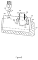
- Figure 2 is a perspective view of a specific embodiment of a battery and circuit board
- Figure 3 is a schematic diagram of a lamp circuit having a DC-to-DC converter
- Figure 4 is a schematic diagram of a current sensing circuit
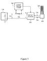
- Figure 5 is a schematic diagram of an alternate embodiment of a battery-powered lamp.
- Figure 6 is a slide-type power tool battery.
- FIG. 1 shows the physical structure of a specific embodiment of a battery powered lamp 100.
- the lamp 100 may include a base 110 that may house a power tool battery 120.
- the base 110 may have a releasable bottom cover 130 configured to provide access to a battery compartment 134.
- a rigid elongated stem 140 may couple the base 110 to a bulb housing 150, which may contain an electrical socket 160.
- the electrical socket 160 may be a standard Edison-type screw-base socket, which accepts a standard compact fluorescent lamp (CFL) 164.
- CFL compact fluorescent lamp
- a CFL is a commercially available self-contained fluorescent lamp configured to be received in a standard screw-type 120 volt AC socket, and is powered by a standard output of 110-125 volts AC.
- the elongated stem 140 may be hollow to facilitate the routing of electrical wiring 165 from a circuit board 170 to the electrical socket 160.
- the lamp 100 may include a decorative shade 180.
- the illustrated lamp or lantern 100 may include a power tool type battery 120.
- Power tool batteries may be used with a variety of power tools and may be rechargeable. Because many households have battery powered power tools, a user may be able to conveniently find an available power tool battery to install in the lamp 100, rather than attempting to locate a large number of D-cell or other types of batteries.
- Commercially available power tool batteries may be used, which may provide various output voltages, such as 19.2 volts, 18 volts, 14.4 volts, or 12 volts, and other voltage outputs.
- Such power tool batteries may be lithium-ion or nickel-cadmium batteries.
- Some suitable batteries may include the Ryobi ® One+ Battery TM , which may have a power output of about 1.7 ampere-hours.
- FIG 2 shows a specific embodiment of the power tool battery 120 and the associated circuit board 170.
- the power tool battery 120 is generally rectangular in shape and may have a cylindrical stem or mast 210 projecting from a top surface 220 of the power tool battery.
- the battery 120 may be releasably connectable to the lamp 100 or the lamp base 110.
- the stem 210 may an electrical connection when inserted into a power tool.
- the stem 210 makes include two or more metal contacts 230 for providing battery power to a load, such as the power tool or the CFL.
- the circuit board 170 may be disposed over the top surface 220 of the battery 120, and may have an aperture 236 configured to receive the mast 210.
- Wiring or mechanical contacts 240 may couple the circuit board 170 to the metal contacts 230 to provide battery power to the circuit board.
- the circuit board 170 may include output terminals 246 configured to deliver the electrical output of the circuit board to terminals of the electrical socket 160 via the wires 165 or other connectors.
- the circuit board 170 need not necessarily be mounted on the power tool battery 120, and may be mounted in any suitable location.
- the circuit board 170 may be mounted to an interior portion of the base 110 using conventional fasteners or mounting hardware.
- FIG. 3 is a schematic diagram of the electronic circuitry that may be mounted on the circuit board 170.
- the circuit board 170 may include a voltage converter 310 configured to convert a DC output voltage 314 of the battery to a lower DC voltage 316.
- the voltage converter 310 may convert an 18 volt or 19.2 volt DC output voltage to a lower DC voltage level 316 of about between 12 volts to about 14.2 or about 15 volts.
- the voltage converter 310 may be a commercially available voltage converter, such as a step-down switching regulator no. LM25576 from National Semiconductor of California. Other suitable voltage converters or regulators may be used.
- a power inverter 320 may convert the lower DC voltage level 316 to an AC voltage level 330.
- the output voltage 330 of the power inverter 320 may be an AC voltage of about 110 volts to about 130 volts.
- the power inverter 320 provides the AC voltage output 330 to the electrical socket 160, and thus provides power to the CFL 164.
- the power inverter 320 may be a commercially available power inverter, such as a DC-to-AC Mobile Inverter no. 0900-36 from PowerLine. Other suitable power inverters may be used.
- a current sensing circuit 360 may be coupled between the voltage converter 310 and the power inverter 320.
- the current sensing circuit 360 may issue an over-current signal 364 when either the voltage converter 310 or the power inverter 320 draws more than a predetermined amount of current or power.
- the maximum current draw may be limited to about 1.25 amperes at about 12 volts or about 0.8 amperes at about 19 volts.
- Such power ratings correspond to about a 15 watt power rating.
- a 15 watt CFL may provide about the same amount of light output as a corresponding 60 watt incandescent light bulb.
- the current sensing circuit 360 may issue the over-current signal 364 when a maximum power level or maximum current draw is reached.
- the over-current signal 364 is shown in dashed lines coupled to the voltage converter to indicate that either the voltage converter 310 or the power inverter 320 may receive the over-current signal.
- a low value sensing resistor 366 may be coupled to the current sensing circuit 360, where a voltage developed across the sensing resistor may be proportional to the current flowing through the sensing resistor. In this way, the current sensing circuit 360 may determine the value of the current flow.
- the current sensing circuit 360 may be a commercially available current or power sensing device, such as a high-side current monitor no. ZXCT1010 available from Zetex Semiconductors. Other suitable current or power sensors and monitors may be used.
- the current sensing circuit 400 may include an operational amplifier 404 having inputs coupled across the sensing resistor 366.
- the operational amplifier 404 may issue an output signal 410 when the maximum permissible current or power draw has been reached.
- a delay circuit 420 may delay the output signal 410 by a predetermined amount of time, for example by about 0.1 seconds to about 1 second. Other suitable delay times, for example, 1 second to 10 seconds, may be used depending upon the application.
- the delay circuit 420 may be a monostable vibrator or one-shot, such as a LM555 timer circuit.
- the output of the delay circuit 420 may drive the base of an output transistor 440, which in turn, may provide the over-current signal 364.
- the battery-powered lamp 100 is configured to operate with a CFL rather than an incandescent light bulb.
- a CFL-type bulb draws much less power than a corresponding incandescent bulb having a similar light output rating. Accordingly, when a CFL is installed in the battery-powered lamp 100, the current sensing circuit 360 or 400 does not sense an over-current condition and thus does not issue the over-current signal 364. This conserves battery life and extends the operating time of the battery-powered lamp 100 before the battery requires recharging. However, because both an incandescent lamp and a CFL both fit into the electrical socket 160, a user may inadvertently install an incandescent light bulb in the battery-powered lamp 100.
- both types of light bulbs are powered by 120 volts AC, both bulbs could be illuminated using the 120 AC output of the power inverter 320. If the user inadvertently installs an incandescent bulb, the incandescent bulb will draw more current or power than may be permitted by the current sensing circuit 360 or 400. Accordingly, the current sensing circuit 360 or 400 will detect the over-current condition and will issue the over-current signal 364 to either the power inverter 320 or the voltage converter 310. This disables or turns off the power inverter 320 or the voltage converter 310, respectively.
- the battery-powered lamp is self-restarting. This means that after the current sensing circuit 400 has disabled or turned off the voltage converter 310 or the power inverter 320 due to improper installation of an incandescent light, the CFL will be automatically illuminated upon installation.
- the power inverter 320 or the voltage converter 310 may be capable of providing the excessive current defining the over-current condition without physical damage, but is disabled or turned off to conserve battery life. However, the power inverter 320 or the voltage converter 310 is not disabled immediately upon detection of the over-current condition. Rather, the delay circuit 420 delays such disabling for a predetermined amount of time. The time delay before turning off the power inverter 320 or the voltage converter 310 permits illumination of an installed incandescent light bulb for an amount of time equal to the time delay, for example, about 0.1 seconds to about 1 second.
- the brief illumination of the incandescent light bulb alerts the user that the wrong type of light bulb has been installed, but that the improper type of light bulb, as well as the lamp circuitry, is nonetheless functional. Without such a time delay, the light bulb would not be illuminated at all, or may only be illuminated for an extremely brief period of time not observable by the user. Thus, without the time delay, the user may believe that the replacement light bulb was burnt-out or that the battery-powered lamp 100 was not functioning. This conserves battery life while preventing inadvertent use of incandescent bulbs in the battery-powered lamp 100.
- a power monitoring circuit based on thermal conditions or temperature parameters may be used. If an excessive amount of current is drawn, a temperature-based monitor may disable or turn off the voltage converter 310 or the power inverter 320 when an elevated temperature is sensed. Because temperature elevation may require a predetermined amount of time to rise, a temperature-based power monitor may inherently include a time delay. Depending upon the sensitivity of the power monitoring circuit, different time delays may be implemented.
- the current sensing circuits 360 and 400 or temperature-base power monitors may be separate from the voltage converter 310 or the power inverter 320, or may be incorporated into the voltage converter or the power inverter, respectively.
- the current sensing circuits 360 and 400 need not necessarily be placed between the voltage converter 310 and the power inverter 320.
- the current sensing circuits 360 and 400 may be placed between the battery 120 and the voltage converter 310.
- a current sensing circuit adapted for AC monitoring may be placed between the power inverter 320 and the electrical socket 160.
- the power inverter 320 may require an input voltage, for example, between about 10 volts to about 15 volts, which may be less than the battery voltage 314 of, for example, about 18 to 19 volts. Accordingly, the voltage converter 310 may convert or "step-down" the battery voltage 314 to a level suitable for input to the power inverter 320. However, if the battery 120 provides an output voltage 314 in the range suitable for input to the power inverter 320, the power converter 310 may be omitted, as shown in Figure 5 . In the alternate embodiment of the circuit of Figure 5 , the battery voltage 314 is provided to the power inverter 320 with no intermediate voltage conversion. The power inverter of Figure 5 may accept an input voltage of about 12 volts to about 25 volts. The power inverter of Figure 5 , for example, is a commercially available power inverter.
- Figure 6 shows a slide type power tool battery 600, which is known. Stem-type power tool batteries, slide-type power tool batteries, or other styles of power tool batteries may also be used in all of the described embodiments and circuitry. Electrical connection to the circuit board 170 can be made through contacts or wiring.
Abstract
Description
- This disclosure relates to lamps. In particular, this disclosure relates to a battery-powered fluorescent lamp.
- Battery-powered lamps may be used when a source of AC power is unavailable or inaccessible. Battery-powered lamps may be convenient when a user is in an outside environment, such as while camping or when otherwise away from buildings or other structures having electricity. Such lamps may be powered by a plurality of standard 1.5 volt D-cell batteries, a 6 volt ganged battery pack, car battery, or other type of battery.
- Some battery-powered lamps may use an incandescent light bulb, while others may use a fluorescent tube. When an incandescent light bulb is used, the batteries must be changed frequently, depending on usage duration, because incandescent light bulbs draw much more power than fluorescent bulbs, thus reducing battery lifetime. The user must have a sufficient supply of batteries on hand to meet lighting demands.
- Some battery-powered lamps are able to interchangeably use an incandescent bulb or a fluorescent bulb. In such lamps, a user may inadvertently install an incandescent light bulb rather than a fluorescent bulb. Inadvertent installation of an incandescent light bulb in a battery-powered lamp designed to use a fluorescent bulb will result in significantly shorter battery life. This results in extra cost for frequent battery replacement. Further, the user may not realize that the shortened battery life is a result of installation of the wrong type of light bulb, and may become dissatisfied with the product.
- According to a first aspect of the invention there is provided a lamp having a light source, comprising a base, a power tool battery providing a DC voltage level, the battery releasably connected to the base, a power inverter for converting the DC voltage level to an AC voltage level, a current sensing circuit operatively coupled to the inverter, the current sensing circuit configured to sense an over-current condition when the inverter draws more than a predetermined amount of current, and wherein the inverter is disabled or the DC voltage level is disconnected if the over-current condition continues for more than a predetermined amount of time so that the light source receives the AC voltage level and is illuminated for the predetermined amount of time before power is removed.
- According to a further aspect the invention provides a lamp having a light source, comprising a base, a power tool battery providing a first DC voltage level, the battery releasably connected the base, a voltage converter configured to convert the first DC voltage level to a second DC voltage level, a power inverter for converting the second DC voltage level to an AC voltage level, a current sensing circuit operatively coupled to the converter or the inverter, and configured to issue an over-current signal if the converter or the inverter draws more than a predetermined amount of current or power, and a delay circuit configured to disable the converter or the inverter after a predetermined amount of time after receiving the over-current signal so that the light source receives the AC voltage level and is illuminated for the predetermined amount of time before power is removed.
- According to a still further aspect the invention provides a battery-powered lamp having a light source, comprising a base, a power tool battery providing a first DC voltage level, the battery releasably coupled to the base, a stem coupled to the base and configured to support the light source, a voltage converter configured to convert the first DC voltage level to a second DC voltage level, a power inverter for converting the second DC voltage level to an AC voltage level, the AC voltage level provided to the light source, a current sensing circuit operatively coupled to the converter or the inverter, the current sensing circuit configured to sense an over-current condition when the converter or the inverter draws more than a predetermined amount of current, and wherein the converter or inverter is disabled if the over-current condition continues for more than a predetermined amount of time so that the light source receives the AC voltage level and is illuminated for the predetermined amount of time before power is removed.
- According to a still further aspect the invention provides a battery-powered lamp having a light source, comprising a power tool battery providing a first DC voltage level, a base for housing the power tool battery, an electrical socket for receiving the light source, a hollow stem configured to couple the base with the electrical socket and provide electrical connection between the battery and the electrical socket, a voltage converter configured to convert the first DC voltage level to a second DC voltage level, a power inverter for converting the second DC voltage level to an AC voltage level, the AC voltage level provided to the light source, a current sensing circuit operatively coupled to the converter or the inverter, the current sensing circuit configured to issue an over-current signal when the converter or the inverter draws more than a predetermined amount of current or power, a delay circuit configured to receive the over-current signal and disable the converter or the inverter in response thereto; and wherein the delay circuit delays disabling the converter or the inverter for a predetermined amount of time so that the light source receives the AC voltage level and is illuminated for the predetermined amount of time before power is removed.
- The predetermined amount of time is preferably between 0.1 seconds and 1.0 seconds.
- The over-current condition may occur if the AC voltage level is supplied to an incandescent light bulb, the over-current condition causing the inverter to be disabled after the predetermined amount of time has elapsed. The incandescent light bulb receives the AC voltage during the over-current condition for the predetermined amount of time so as to alert a user as to installation of the incandescent light bulb.
- The battery may be a stem-type power tool battery or a slide-type power tool battery.
- The first DC voltage level may be greater than the second, and may be greater than 17 volts or between 11 and 15 volts.
- The lamp may include a lamp stem coupled to the base to support the light source.
- If the light source is a compact fluorescent lamp, an amount of current or power drawn is less than the predetermined amount of current or power.
-
Figure 1 is a perspective view of a specific embodiment of a battery-powered lamp; -
Figure 2 is a perspective view of a specific embodiment of a battery and circuit board; -
Figure 3 is a schematic diagram of a lamp circuit having a DC-to-DC converter; -
Figure 4 is a schematic diagram of a current sensing circuit; -
Figure 5 is a schematic diagram of an alternate embodiment of a battery-powered lamp; and -
Figure 6 is a slide-type power tool battery. - The invention is described with reference to the drawings in which like elements are referred to by like numerals. The relationship and function of the various elements of this invention are better understood by the following description. Each aspect so defined may be combined with any other aspect or aspects unless clearly indicated to the contrary. The embodiments described below are by way of example only, and the invention is not limited to the embodiments illustrated in the drawings.
-
Figure 1 shows the physical structure of a specific embodiment of a battery poweredlamp 100. Thelamp 100 may include abase 110 that may house apower tool battery 120. Thebase 110 may have areleasable bottom cover 130 configured to provide access to a battery compartment 134. A rigidelongated stem 140 may couple thebase 110 to abulb housing 150, which may contain anelectrical socket 160. Theelectrical socket 160 may be a standard Edison-type screw-base socket, which accepts a standard compact fluorescent lamp (CFL) 164. A CFL is a commercially available self-contained fluorescent lamp configured to be received in a standard screw-type 120 volt AC socket, and is powered by a standard output of 110-125 volts AC. Theelongated stem 140 may be hollow to facilitate the routing ofelectrical wiring 165 from acircuit board 170 to theelectrical socket 160. Thelamp 100 may include adecorative shade 180. - Unlike conventional lamps, which may use a plurality of D-cell batteries, the illustrated lamp or
lantern 100 may include a powertool type battery 120. Power tool batteries may be used with a variety of power tools and may be rechargeable. Because many households have battery powered power tools, a user may be able to conveniently find an available power tool battery to install in thelamp 100, rather than attempting to locate a large number of D-cell or other types of batteries. Commercially available power tool batteries may be used, which may provide various output voltages, such as 19.2 volts, 18 volts, 14.4 volts, or 12 volts, and other voltage outputs. Such power tool batteries may be lithium-ion or nickel-cadmium batteries. Some suitable batteries may include the Ryobi® One+ Battery™, which may have a power output of about 1.7 ampere-hours. -
Figure 2 shows a specific embodiment of thepower tool battery 120 and theassociated circuit board 170. Thepower tool battery 120 is generally rectangular in shape and may have a cylindrical stem ormast 210 projecting from atop surface 220 of the power tool battery. Thebattery 120 may be releasably connectable to thelamp 100 or thelamp base 110. Thestem 210 may an electrical connection when inserted into a power tool. Thestem 210 makes include two or moremetal contacts 230 for providing battery power to a load, such as the power tool or the CFL. Thecircuit board 170 may be disposed over thetop surface 220 of thebattery 120, and may have anaperture 236 configured to receive themast 210. Wiring ormechanical contacts 240 may couple thecircuit board 170 to themetal contacts 230 to provide battery power to the circuit board. Thecircuit board 170 may includeoutput terminals 246 configured to deliver the electrical output of the circuit board to terminals of theelectrical socket 160 via thewires 165 or other connectors. Thecircuit board 170 need not necessarily be mounted on thepower tool battery 120, and may be mounted in any suitable location. For example, thecircuit board 170 may be mounted to an interior portion of thebase 110 using conventional fasteners or mounting hardware. -
Figure 3 is a schematic diagram of the electronic circuitry that may be mounted on thecircuit board 170. Thecircuit board 170 may include avoltage converter 310 configured to convert aDC output voltage 314 of the battery to alower DC voltage 316. For example, thevoltage converter 310 may convert an 18 volt or 19.2 volt DC output voltage to a lowerDC voltage level 316 of about between 12 volts to about 14.2 or about 15 volts. Thevoltage converter 310 may be a commercially available voltage converter, such as a step-down switching regulator no. LM25576 from National Semiconductor of California. Other suitable voltage converters or regulators may be used. - A
power inverter 320 may convert the lowerDC voltage level 316 to anAC voltage level 330. Theoutput voltage 330 of thepower inverter 320 may be an AC voltage of about 110 volts to about 130 volts. Thepower inverter 320 provides theAC voltage output 330 to theelectrical socket 160, and thus provides power to theCFL 164. Thepower inverter 320 may be a commercially available power inverter, such as a DC-to-AC Mobile Inverter no. 0900-36 from PowerLine. Other suitable power inverters may be used. - A
current sensing circuit 360 may be coupled between thevoltage converter 310 and thepower inverter 320. Thecurrent sensing circuit 360 may issue anover-current signal 364 when either thevoltage converter 310 or thepower inverter 320 draws more than a predetermined amount of current or power. For example, the maximum current draw may be limited to about 1.25 amperes at about 12 volts or about 0.8 amperes at about 19 volts. Such power ratings correspond to about a 15 watt power rating. A 15 watt CFL may provide about the same amount of light output as a corresponding 60 watt incandescent light bulb. Thecurrent sensing circuit 360 may issue theover-current signal 364 when a maximum power level or maximum current draw is reached. Theover-current signal 364 is shown in dashed lines coupled to the voltage converter to indicate that either thevoltage converter 310 or thepower inverter 320 may receive the over-current signal. - A low
value sensing resistor 366 may be coupled to thecurrent sensing circuit 360, where a voltage developed across the sensing resistor may be proportional to the current flowing through the sensing resistor. In this way, thecurrent sensing circuit 360 may determine the value of the current flow. Thecurrent sensing circuit 360 may be a commercially available current or power sensing device, such as a high-side current monitor no. ZXCT1010 available from Zetex Semiconductors. Other suitable current or power sensors and monitors may be used. -
Figure 4 shows a specific embodiment of the current sensing circuit 400. The current sensing circuit 400 may include anoperational amplifier 404 having inputs coupled across thesensing resistor 366. Theoperational amplifier 404 may issue anoutput signal 410 when the maximum permissible current or power draw has been reached. Adelay circuit 420 may delay theoutput signal 410 by a predetermined amount of time, for example by about 0.1 seconds to about 1 second. Other suitable delay times, for example, 1 second to 10 seconds, may be used depending upon the application. Thedelay circuit 420 may be a monostable vibrator or one-shot, such as a LM555 timer circuit. The output of thedelay circuit 420 may drive the base of an output transistor 440, which in turn, may provide theover-current signal 364. - The battery-powered
lamp 100 is configured to operate with a CFL rather than an incandescent light bulb. A CFL-type bulb draws much less power than a corresponding incandescent bulb having a similar light output rating. Accordingly, when a CFL is installed in the battery-poweredlamp 100, thecurrent sensing circuit 360 or 400 does not sense an over-current condition and thus does not issue theover-current signal 364. This conserves battery life and extends the operating time of the battery-poweredlamp 100 before the battery requires recharging. However, because both an incandescent lamp and a CFL both fit into theelectrical socket 160, a user may inadvertently install an incandescent light bulb in the battery-poweredlamp 100. Because both types of light bulbs are powered by 120 volts AC, both bulbs could be illuminated using the 120 AC output of thepower inverter 320. If the user inadvertently installs an incandescent bulb, the incandescent bulb will draw more current or power than may be permitted by thecurrent sensing circuit 360 or 400. Accordingly, thecurrent sensing circuit 360 or 400 will detect the over-current condition and will issue theover-current signal 364 to either thepower inverter 320 or thevoltage converter 310. This disables or turns off thepower inverter 320 or thevoltage converter 310, respectively. - The battery-powered lamp is self-restarting. This means that after the current sensing circuit 400 has disabled or turned off the
voltage converter 310 or thepower inverter 320 due to improper installation of an incandescent light, the CFL will be automatically illuminated upon installation. - Note that the
power inverter 320 or thevoltage converter 310 may be capable of providing the excessive current defining the over-current condition without physical damage, but is disabled or turned off to conserve battery life. However, thepower inverter 320 or thevoltage converter 310 is not disabled immediately upon detection of the over-current condition. Rather, thedelay circuit 420 delays such disabling for a predetermined amount of time. The time delay before turning off thepower inverter 320 or thevoltage converter 310 permits illumination of an installed incandescent light bulb for an amount of time equal to the time delay, for example, about 0.1 seconds to about 1 second. - The brief illumination of the incandescent light bulb alerts the user that the wrong type of light bulb has been installed, but that the improper type of light bulb, as well as the lamp circuitry, is nonetheless functional. Without such a time delay, the light bulb would not be illuminated at all, or may only be illuminated for an extremely brief period of time not observable by the user. Thus, without the time delay, the user may believe that the replacement light bulb was burnt-out or that the battery-powered
lamp 100 was not functioning. This conserves battery life while preventing inadvertent use of incandescent bulbs in the battery-poweredlamp 100. - Other current sensing circuits or power monitoring circuits may be used. For example, a power monitoring circuit based on thermal conditions or temperature parameters may be used. If an excessive amount of current is drawn, a temperature-based monitor may disable or turn off the
voltage converter 310 or thepower inverter 320 when an elevated temperature is sensed. Because temperature elevation may require a predetermined amount of time to rise, a temperature-based power monitor may inherently include a time delay. Depending upon the sensitivity of the power monitoring circuit, different time delays may be implemented. - The
current sensing circuits 360 and 400 or temperature-base power monitors may be separate from thevoltage converter 310 or thepower inverter 320, or may be incorporated into the voltage converter or the power inverter, respectively. Thecurrent sensing circuits 360 and 400 need not necessarily be placed between thevoltage converter 310 and thepower inverter 320. Alternatively, thecurrent sensing circuits 360 and 400 may be placed between thebattery 120 and thevoltage converter 310. In another embodiment, a current sensing circuit adapted for AC monitoring may be placed between thepower inverter 320 and theelectrical socket 160. - With regard to
Figure 3 , thepower inverter 320 may require an input voltage, for example, between about 10 volts to about 15 volts, which may be less than thebattery voltage 314 of, for example, about 18 to 19 volts. Accordingly, thevoltage converter 310 may convert or "step-down" thebattery voltage 314 to a level suitable for input to thepower inverter 320. However, if thebattery 120 provides anoutput voltage 314 in the range suitable for input to thepower inverter 320, thepower converter 310 may be omitted, as shown inFigure 5 . In the alternate embodiment of the circuit ofFigure 5 , thebattery voltage 314 is provided to thepower inverter 320 with no intermediate voltage conversion. The power inverter ofFigure 5 may accept an input voltage of about 12 volts to about 25 volts. The power inverter ofFigure 5 , for example, is a commercially available power inverter. -
Figure 6 shows a slide typepower tool battery 600, which is known. Stem-type power tool batteries, slide-type power tool batteries, or other styles of power tool batteries may also be used in all of the described embodiments and circuitry. Electrical connection to thecircuit board 170 can be made through contacts or wiring. - While the invention has been illustrated and described in detail in the drawings and foregoing description, the same is to be considered as illustrative and not restrictive in character, it being understood that only exemplary embodiments have been shown and described and do not limit the scope of the invention in any manner. The illustrative embodiments are not exclusive of each other or of other embodiments not recited herein. Accordingly, the invention also provides embodiments that comprise combinations of one or more of the illustrative embodiments described above. Modifications and variations of the invention as herein set forth can be made without departing from the scope thereof, and, therefore, only such limitations should be imposed as are indicated by the appended claims.
Claims (25)
- A lamp having a light source, comprising:a base;a power tool battery providing a DC voltage level, the battery releasably connected to the base;a power inverter for converting the DC voltage level to an AC voltage level;a current sensing circuit operatively coupled to the inverter;the current sensing circuit configured to sense an over-current condition when the inverter draws more than a predetermined amount of current; andwherein the inverter is disabled or the DC voltage level is disconnected if the over-current condition continues for more than a predetermined amount of time so that the light source receives the AC voltage level and is illuminated for the predetermined amount of time before power is removed.
- The lamp according to claim 1, wherein the predetermined amount of time is between 0.1 seconds and 1.0 seconds.
- The lamp according to claim 1 or 2, wherein the over-current condition occurs if the AC voltage level is supplied to an incandescent light bulb, the over-current condition causing the inverter to be disabled after the predetermined amount of time has elapsed.
- The lamp according to claim 3, wherein the incandescent light bulb receives the AC voltage during the over-current condition for the predetermined amount of time so as to alert a user as to installation of the incandescent light bulb.
- The lamp according to any preceding claim, wherein the battery is a stem-type power tool battery or a slide-type power tool battery.
- The lamp according to any preceding claim, further including a lamp stem coupled to the base to support the light source.
- A lamp having a light source, comprising:a base;a power tool battery providing a first DC voltage level, the battery releasably connected the base;a voltage converter configured to convert the first DC voltage level to a second DC voltage level;a power inverter for converting the second DC voltage level to an AC voltage level;a current sensing circuit operatively coupled to the converter or the inverter, and configured to issue an over-current signal if the converter or the inverter draws more than a predetermined amount of current or power; anda delay circuit configured to disable the converter or the inverter after a predetermined amount of time after receiving the over-current signal so that the light source receives the AC voltage level and is illuminated for the predetermined amount of time before power is removed.
- The lamp according to claim 7, wherein the predetermined amount of time is between 0.1 seconds and 1.0 seconds.
- The lamp according to claim 7 or 8, wherein an over-current condition occurs if the AC voltage level is supplied to an incandescent light bulb, the over-current condition causing the converter or the inverter to be disabled after the predetermined amount of time has elapsed.
- The lamp according to claim 9, wherein the incandescent light bulb receives the AC voltage during the over-current condition for the predetermined amount of time so as to alert a user of the over-current condition.
- The lamp according to claim 9 or 10, wherein the incandescent light bulb is illuminated during the over-current condition.
- The lamp according to claim 7 or 8, wherein if the light source is a compact fluorescent lamp, an amount of current or power drawn is less than the predetermined amount of current or power.
- The lamp according to any one of claims 7 to 12, wherein the first DC voltage level is greater than the second DC voltage level.
- The lamp according to any one of claims 7 to 13, wherein the first DC voltage level is greater than 17 volts.
- The lamp according to any one of claims 7 to 13, wherein the second DC voltage level is between 11 volts and 15 volts.
- The lamp according to any one of claims 7 to 15, wherein the battery is a stem-type power tool battery or a slide-type power tool battery.
- The lamp according to any one of claims 7 to 16, further including a lamp stem coupled to the base to support the light source.
- A battery-powered lamp having a light source, comprising:a base;a power tool battery providing a first DC voltage level, the battery releasably coupled to the base;a stem coupled to the base and configured to support the light source;a voltage converter configured to convert the first DC voltage level to a second DC voltage level;a power inverter for converting the second DC voltage level to an AC voltage level, the AC voltage level provided to the light source;a current sensing circuit operatively coupled to the converter or the inverter;the current sensing circuit configured to sense an over-current condition when the converter or the inverter draws more than a predetermined amount of current; andwherein the converter or inverter is disabled if the over-current condition continues for more than a predetermined amount of time so that the light source receives the AC voltage level and is illuminated for the predetermined amount of time before power is removed.
- The lamp according to claim 18, wherein the predetermined amount of time is between 0.1 seconds and 1.0 seconds;
- The lamp according to claim 18 or 19, wherein the over-current condition occurs if the AC voltage level is supplied to an incandescent light bulb, the over-current condition causing the converter or the inverter to be disabled after the predetermined amount of time has elapsed.
- The lamp according to claim 20, wherein the incandescent light bulb receives the AC voltage during the over-current condition for the predetermined amount of time so as to alert a user of the over-current condition.
- The lamp according to claim 20 or 21, wherein the incandescent light bulb is illuminated during the over-current condition.
- The lamp according to claim 18 or 19, wherein if the light source is a compact fluorescent lamp, an amount of current or power drawn is less than the predetermined amount of current or power.
- A battery-powered lamp having a light source, comprising:a power tool battery providing a first DC voltage level;a base for housing the power tool battery;an electrical socket for receiving the light source;a hollow stem configured to couple the base with the electrical socket and provide electrical connection between the battery and the electrical socket;a voltage converter configured to convert the first DC voltage level to a second DC voltage level;a power inverter for converting the second DC voltage level to an AC voltage level, the AC voltage level provided to the light source;a current sensing circuit operatively coupled to the converter or the inverter;the current sensing circuit configured to issue an over-current signal when the converter or the inverter draws more than a predetermined amount of current or power; a delay circuit configured to receive the over-current signal and disable the converter or the inverter in response thereto; and whereinthe delay circuit delays disabling the converter or the inverter for a predetermined amount of time so that the light source receives the AC voltage level and is illuminated for the predetermined amount of time before power is removed.
- The lamp according to claim 1, wherein the DC voltage level is greater than 17 volts.
Applications Claiming Priority (1)
| Application Number | Priority Date | Filing Date | Title |
|---|---|---|---|
| US11/931,780 US7923934B2 (en) | 2007-10-31 | 2007-10-31 | Battery-powered fluorescent lamp |
Publications (1)
| Publication Number | Publication Date |
|---|---|
| EP2056652A1 true EP2056652A1 (en) | 2009-05-06 |
Family
ID=40260794
Family Applications (1)
| Application Number | Title | Priority Date | Filing Date |
|---|---|---|---|
| EP08252249A Withdrawn EP2056652A1 (en) | 2007-10-31 | 2008-07-02 | Battery-powered fluorescent lamp |
Country Status (6)
| Country | Link |
|---|---|
| US (1) | US7923934B2 (en) |
| EP (1) | EP2056652A1 (en) |
| CN (1) | CN101424379B (en) |
| AU (1) | AU2008202792B2 (en) |
| CA (1) | CA2639447A1 (en) |
| MX (1) | MX2008014001A (en) |
Cited By (2)
| Publication number | Priority date | Publication date | Assignee | Title |
|---|---|---|---|---|
| GB2548158A (en) * | 2016-03-11 | 2017-09-13 | Kirk Cornell | Portable energy device, method of use and manufacture thereof |
| US10948166B2 (en) | 2016-08-30 | 2021-03-16 | Panasonic Intellectual Property Management Co., Ltd. | Lighting apparatus |
Families Citing this family (2)
| Publication number | Priority date | Publication date | Assignee | Title |
|---|---|---|---|---|
| US8115397B2 (en) * | 2011-01-04 | 2012-02-14 | Greenwave Reality PTE, Ltd. | Power failure reporting in a networked light |
| EP3734144B1 (en) * | 2019-04-29 | 2022-11-09 | Black & Decker Inc. | Shed light |
Citations (10)
| Publication number | Priority date | Publication date | Assignee | Title |
|---|---|---|---|---|
| US3809882A (en) * | 1971-01-20 | 1974-05-07 | Unique Devices Eng & Consultin | Lighting device |
| US4706177A (en) * | 1985-11-14 | 1987-11-10 | Elliot Josephson | DC-AC inverter with overload driving capability |
| US5015919A (en) * | 1989-07-19 | 1991-05-14 | Led Corporation N.V. | Emergency lighting system provided with a fluorescent tube |
| EP0466031A1 (en) * | 1990-07-06 | 1992-01-15 | Zumtobel Aktiengesellschaft | Dimmer circuit |
| GB2326543A (en) * | 1997-06-19 | 1998-12-23 | Toshiba Lighting & Technology | Arrangement to detect the type of discharge lamp coupled to a ballast |
| WO2000079675A1 (en) * | 1999-06-16 | 2000-12-28 | Fronius Schweissmaschinen Produktion Gmbh & Co. Kg | Method for identifying a load that can be connected according to demand to a power inverter, and a corresponding load identification system |
| US20040218384A1 (en) * | 2003-05-02 | 2004-11-04 | James Newton | Rechargeable fluorescent task lamp |
| DE102004045435A1 (en) * | 2004-09-18 | 2006-03-23 | Man Nutzfahrzeuge Ag | Light bulb or LED-headlamp function monitoring device for motor vehicle, has mechanism detecting that bulb or headlamp is turned out in electric circuit, where function or non-function of bulb or lamp is established by electronic circuit |
| US20060120090A1 (en) * | 2004-12-07 | 2006-06-08 | Black & Decker Inc. | Fluorescent flashlight |
| US20060139927A1 (en) * | 2004-05-28 | 2006-06-29 | Alert Safety Lite Products Co., Inc. | Rechargeable fluorescent utility light |
Family Cites Families (32)
| Publication number | Priority date | Publication date | Assignee | Title |
|---|---|---|---|---|
| US3435206A (en) | 1966-12-19 | 1969-03-25 | Richard C Swanson | Portable fluorescent lamp |
| US3501674A (en) | 1967-07-13 | 1970-03-17 | Battery Lite Corp | High frequency portable power supply for a fluorescent lamp |
| US3671803A (en) | 1970-01-28 | 1972-06-20 | Frank E Hoxsie | Portable self-starting fluorescent lamp |
| US3953768A (en) | 1970-12-23 | 1976-04-27 | Meredith Ronald D | Portable fluorescent lamp and inverter therefor |
| US3758823A (en) | 1971-12-23 | 1973-09-11 | Jettson Engineering Co Inc | Battery powered fluorescent light |
| US3778677A (en) | 1972-08-25 | 1973-12-11 | Lowrance Electronics Mfg | Inverter ballast circuit |
| GB1570277A (en) | 1975-10-01 | 1980-06-25 | Sonca Ind Ltd | Fluorescent lamp arrangement |
| US4096410A (en) | 1976-07-14 | 1978-06-20 | General Electric Company | Inverter circuit protection |
| US6459213B1 (en) | 1978-03-20 | 2002-10-01 | Ole K. Nilssen | Ballast for parallel-connected lamps |
| US5191262A (en) | 1978-12-28 | 1993-03-02 | Nilssen Ole K | Extra cost-effective electronic ballast |
| US5446346A (en) | 1978-03-20 | 1995-08-29 | Nilssen; Ole K. | Electronic ballast with controlled DC supply voltage |
| US5691603A (en) | 1980-08-14 | 1997-11-25 | Nilssen; Ole K. | Electronic ballast with multiple lamp loads |
| US5449979A (en) | 1992-09-25 | 1995-09-12 | Matsushita Electric Works, Ltd. | Inverter power supply |
| US5489891A (en) * | 1993-01-29 | 1996-02-06 | Noval Controls Sdn Bhd | Control means for lighting devices |
| JP3197169B2 (en) * | 1994-09-08 | 2001-08-13 | 株式会社小糸製作所 | Lighting circuit of discharge lamp |
| US6107744A (en) | 1995-11-29 | 2000-08-22 | Bavaro; Joseph P. | Back-up electrical systems |
| US5734229A (en) * | 1995-11-29 | 1998-03-31 | Bavaro; Joseph P. | Back-up electrical system for portable table lamps |
| US5945788A (en) * | 1998-03-30 | 1999-08-31 | Motorola Inc. | Electronic ballast with inverter control circuit |
| US5969483A (en) * | 1998-03-30 | 1999-10-19 | Motorola | Inverter control method for electronic ballasts |
| JP3736171B2 (en) | 1998-03-31 | 2006-01-18 | 東芝ライテック株式会社 | Light bulb shaped fluorescent lamp and lighting fixture |
| US6573665B2 (en) | 2000-08-01 | 2003-06-03 | Spectronics Corporation | Inspection lamp with interchangeable AC or DC power cords |
| US6400104B1 (en) | 2000-09-12 | 2002-06-04 | Byung Il Ham | Fluorescent lamp assembly with nightlight |
| JP2002154074A (en) | 2000-11-16 | 2002-05-28 | Makita Corp | Lighting system for power tool |
| US7064494B2 (en) | 2001-04-12 | 2006-06-20 | Matsushita Electric Industrial Co., Ltd. | Discharge lamp operating apparatus and self-ballasted electrodeless discharge lamp |
| IL147878A0 (en) | 2002-01-28 | 2002-08-14 | Impolight Ltd | An illumination unit for normal and emergency operation |
| US7109665B2 (en) | 2002-06-05 | 2006-09-19 | International Rectifier Corporation | Three-way dimming CFL ballast |
| CN100346673C (en) | 2002-09-24 | 2007-10-31 | 东芝照明技术株式会社 | High voltage discharge lamp turn-on device and lighting device |
| JP4467242B2 (en) * | 2003-02-14 | 2010-05-26 | 株式会社パイオラックス | Securing clip |
| US7256547B2 (en) | 2003-03-24 | 2007-08-14 | Toshiba Lighting & Technology Corporation | Self-ballasted fluorescent lamp and luminaire |
| US20050258954A1 (en) * | 2004-03-11 | 2005-11-24 | Ruskin Thomas R | Apparatus and method for providing motion actuated light |
| WO2006052910A2 (en) * | 2004-11-07 | 2006-05-18 | Milwaukee Electric Tool Corporation | Light |
| US7429118B1 (en) * | 2007-04-06 | 2008-09-30 | Nathan Borowiak | Light way |
-
2007
- 2007-10-31 US US11/931,780 patent/US7923934B2/en not_active Expired - Fee Related
-
2008
- 2008-06-24 AU AU2008202792A patent/AU2008202792B2/en not_active Ceased
- 2008-07-02 EP EP08252249A patent/EP2056652A1/en not_active Withdrawn
- 2008-07-25 CN CN2008101332899A patent/CN101424379B/en not_active Expired - Fee Related
- 2008-09-09 CA CA002639447A patent/CA2639447A1/en not_active Abandoned
- 2008-10-30 MX MX2008014001A patent/MX2008014001A/en unknown
Patent Citations (10)
| Publication number | Priority date | Publication date | Assignee | Title |
|---|---|---|---|---|
| US3809882A (en) * | 1971-01-20 | 1974-05-07 | Unique Devices Eng & Consultin | Lighting device |
| US4706177A (en) * | 1985-11-14 | 1987-11-10 | Elliot Josephson | DC-AC inverter with overload driving capability |
| US5015919A (en) * | 1989-07-19 | 1991-05-14 | Led Corporation N.V. | Emergency lighting system provided with a fluorescent tube |
| EP0466031A1 (en) * | 1990-07-06 | 1992-01-15 | Zumtobel Aktiengesellschaft | Dimmer circuit |
| GB2326543A (en) * | 1997-06-19 | 1998-12-23 | Toshiba Lighting & Technology | Arrangement to detect the type of discharge lamp coupled to a ballast |
| WO2000079675A1 (en) * | 1999-06-16 | 2000-12-28 | Fronius Schweissmaschinen Produktion Gmbh & Co. Kg | Method for identifying a load that can be connected according to demand to a power inverter, and a corresponding load identification system |
| US20040218384A1 (en) * | 2003-05-02 | 2004-11-04 | James Newton | Rechargeable fluorescent task lamp |
| US20060139927A1 (en) * | 2004-05-28 | 2006-06-29 | Alert Safety Lite Products Co., Inc. | Rechargeable fluorescent utility light |
| DE102004045435A1 (en) * | 2004-09-18 | 2006-03-23 | Man Nutzfahrzeuge Ag | Light bulb or LED-headlamp function monitoring device for motor vehicle, has mechanism detecting that bulb or headlamp is turned out in electric circuit, where function or non-function of bulb or lamp is established by electronic circuit |
| US20060120090A1 (en) * | 2004-12-07 | 2006-06-08 | Black & Decker Inc. | Fluorescent flashlight |
Cited By (3)
| Publication number | Priority date | Publication date | Assignee | Title |
|---|---|---|---|---|
| GB2548158A (en) * | 2016-03-11 | 2017-09-13 | Kirk Cornell | Portable energy device, method of use and manufacture thereof |
| US10948166B2 (en) | 2016-08-30 | 2021-03-16 | Panasonic Intellectual Property Management Co., Ltd. | Lighting apparatus |
| EP3508785B1 (en) * | 2016-08-30 | 2023-11-08 | Panasonic Intellectual Property Management Co., Ltd. | Lighting apparatus |
Also Published As
| Publication number | Publication date |
|---|---|
| AU2008202792B2 (en) | 2013-08-22 |
| CN101424379A (en) | 2009-05-06 |
| US7923934B2 (en) | 2011-04-12 |
| US20090108758A1 (en) | 2009-04-30 |
| CN101424379B (en) | 2012-01-25 |
| MX2008014001A (en) | 2009-05-12 |
| AU2008202792A1 (en) | 2009-05-14 |
| CA2639447A1 (en) | 2009-04-30 |
Similar Documents
| Publication | Publication Date | Title |
|---|---|---|
| US20070247840A1 (en) | Compact emergency illumination unit | |
| US7688029B2 (en) | Portable battery powered appliance and method of operation | |
| US7705542B2 (en) | Flashlight | |
| US20160356469A1 (en) | Supplemental, backup or emergency lighting systems and methods | |
| US20130334881A1 (en) | Emergency light and charger system | |
| US9232593B2 (en) | Converting a lamp for continued operation following a line current failure | |
| US20070109773A1 (en) | Portable electric lighting fixture | |
| WO2006030432A1 (en) | An illumination unit employing a led or a fluorescent lamp for normal and emergency operation | |
| US20200340635A1 (en) | Lighting arrangement with battery backup | |
| US7923934B2 (en) | Battery-powered fluorescent lamp | |
| CN108605404A (en) | Have a power failure safe light bulb | |
| US6894439B2 (en) | Portable power converter pack | |
| US9089034B2 (en) | Lighting device and luminaire including the same | |
| JP2008074258A (en) | Portable power source device | |
| US20080303677A1 (en) | Alarm Apparatus and Adaptor | |
| JP2009151946A (en) | Guide light device, and guide light fixture | |
| JP2015095328A (en) | Lighting device, light source unit used for the same, and illumination apparatus | |
| US20050001564A1 (en) | Solar powered lamp having an auxiliary startup device | |
| KR920007377B1 (en) | Electrical source device for lightening | |
| JP2017228427A (en) | Illumination device | |
| EP0806608A2 (en) | Lampshade having an emergency lighting system | |
| KR910001179Y1 (en) | Lighting apparatus | |
| JPH10199312A (en) | Lighting system | |
| US20100271801A1 (en) | Storm Light | |
| KR20040005797A (en) | Apparatus for identifying lighting state of lamp |
Legal Events
| Date | Code | Title | Description |
|---|---|---|---|
| PUAI | Public reference made under article 153(3) epc to a published international application that has entered the european phase |
Free format text: ORIGINAL CODE: 0009012 |
|
| AK | Designated contracting states |
Kind code of ref document: A1 Designated state(s): AT BE BG CH CY CZ DE DK EE ES FI FR GB GR HR HU IE IS IT LI LT LU LV MC MT NL NO PL PT RO SE SI SK TR |
|
| AX | Request for extension of the european patent |
Extension state: AL BA MK RS |
|
| 17Q | First examination report despatched |
Effective date: 20090928 |
|
| AKX | Designation fees paid |
Designated state(s): AT BE BG CH CY CZ DE DK EE ES FI FR GB GR HR HU IE IS IT LI LT LU LV MC MT NL NO PL PT RO SE SI SK TR |
|
| STAA | Information on the status of an ep patent application or granted ep patent |
Free format text: STATUS: THE APPLICATION IS DEEMED TO BE WITHDRAWN |
|
| 18D | Application deemed to be withdrawn |
Effective date: 20160713 |