EP3508754A1 - Hand-powered self-driven travelling machine - Google Patents
Hand-powered self-driven travelling machine Download PDFInfo
- Publication number
- EP3508754A1 EP3508754A1 EP17883357.0A EP17883357A EP3508754A1 EP 3508754 A1 EP3508754 A1 EP 3508754A1 EP 17883357 A EP17883357 A EP 17883357A EP 3508754 A1 EP3508754 A1 EP 3508754A1
- Authority
- EP
- European Patent Office
- Prior art keywords
- wheels
- hand
- traveling machine
- motor
- rotate
- Prior art date
- Legal status (The legal status is an assumption and is not a legal conclusion. Google has not performed a legal analysis and makes no representation as to the accuracy of the status listed.)
- Granted
Links
Images






Classifications
-
- A—HUMAN NECESSITIES
- A01—AGRICULTURE; FORESTRY; ANIMAL HUSBANDRY; HUNTING; TRAPPING; FISHING
- A01D—HARVESTING; MOWING
- A01D34/00—Mowers; Mowing apparatus of harvesters
- A01D34/01—Mowers; Mowing apparatus of harvesters characterised by features relating to the type of cutting apparatus
- A01D34/412—Mowers; Mowing apparatus of harvesters characterised by features relating to the type of cutting apparatus having rotating cutters
- A01D34/63—Mowers; Mowing apparatus of harvesters characterised by features relating to the type of cutting apparatus having rotating cutters having cutters rotating about a vertical axis
- A01D34/67—Mowers; Mowing apparatus of harvesters characterised by features relating to the type of cutting apparatus having rotating cutters having cutters rotating about a vertical axis hand-guided by a walking operator
- A01D34/68—Mowers; Mowing apparatus of harvesters characterised by features relating to the type of cutting apparatus having rotating cutters having cutters rotating about a vertical axis hand-guided by a walking operator with motor driven cutters or wheels
- A01D34/69—Mowers; Mowing apparatus of harvesters characterised by features relating to the type of cutting apparatus having rotating cutters having cutters rotating about a vertical axis hand-guided by a walking operator with motor driven cutters or wheels with motor driven wheels
-
- A—HUMAN NECESSITIES
- A01—AGRICULTURE; FORESTRY; ANIMAL HUSBANDRY; HUNTING; TRAPPING; FISHING
- A01D—HARVESTING; MOWING
- A01D42/00—Mowers convertible to apparatus for purposes other than mowing; Mowers capable of performing operations other than mowing
- A01D42/06—Sweeping or cleaning lawns or other surfaces
- A01D42/08—Sweeping snow
-
- A—HUMAN NECESSITIES
- A01—AGRICULTURE; FORESTRY; ANIMAL HUSBANDRY; HUNTING; TRAPPING; FISHING
- A01D—HARVESTING; MOWING
- A01D34/00—Mowers; Mowing apparatus of harvesters
- A01D34/01—Mowers; Mowing apparatus of harvesters characterised by features relating to the type of cutting apparatus
- A01D34/412—Mowers; Mowing apparatus of harvesters characterised by features relating to the type of cutting apparatus having rotating cutters
- A01D34/63—Mowers; Mowing apparatus of harvesters characterised by features relating to the type of cutting apparatus having rotating cutters having cutters rotating about a vertical axis
- A01D34/67—Mowers; Mowing apparatus of harvesters characterised by features relating to the type of cutting apparatus having rotating cutters having cutters rotating about a vertical axis hand-guided by a walking operator
- A01D34/68—Mowers; Mowing apparatus of harvesters characterised by features relating to the type of cutting apparatus having rotating cutters having cutters rotating about a vertical axis hand-guided by a walking operator with motor driven cutters or wheels
- A01D34/6806—Driving mechanisms
- A01D34/6812—Braking or clutching mechanisms
-
- A—HUMAN NECESSITIES
- A01—AGRICULTURE; FORESTRY; ANIMAL HUSBANDRY; HUNTING; TRAPPING; FISHING
- A01D—HARVESTING; MOWING
- A01D34/00—Mowers; Mowing apparatus of harvesters
- A01D34/01—Mowers; Mowing apparatus of harvesters characterised by features relating to the type of cutting apparatus
- A01D34/412—Mowers; Mowing apparatus of harvesters characterised by features relating to the type of cutting apparatus having rotating cutters
- A01D34/63—Mowers; Mowing apparatus of harvesters characterised by features relating to the type of cutting apparatus having rotating cutters having cutters rotating about a vertical axis
- A01D34/67—Mowers; Mowing apparatus of harvesters characterised by features relating to the type of cutting apparatus having rotating cutters having cutters rotating about a vertical axis hand-guided by a walking operator
- A01D34/68—Mowers; Mowing apparatus of harvesters characterised by features relating to the type of cutting apparatus having rotating cutters having cutters rotating about a vertical axis hand-guided by a walking operator with motor driven cutters or wheels
- A01D34/6806—Driving mechanisms
- A01D34/6818—Motor starting mechanisms
-
- A—HUMAN NECESSITIES
- A01—AGRICULTURE; FORESTRY; ANIMAL HUSBANDRY; HUNTING; TRAPPING; FISHING
- A01D—HARVESTING; MOWING
- A01D34/00—Mowers; Mowing apparatus of harvesters
- A01D34/01—Mowers; Mowing apparatus of harvesters characterised by features relating to the type of cutting apparatus
- A01D34/412—Mowers; Mowing apparatus of harvesters characterised by features relating to the type of cutting apparatus having rotating cutters
- A01D34/63—Mowers; Mowing apparatus of harvesters characterised by features relating to the type of cutting apparatus having rotating cutters having cutters rotating about a vertical axis
- A01D34/73—Cutting apparatus
-
- A—HUMAN NECESSITIES
- A01—AGRICULTURE; FORESTRY; ANIMAL HUSBANDRY; HUNTING; TRAPPING; FISHING
- A01D—HARVESTING; MOWING
- A01D34/00—Mowers; Mowing apparatus of harvesters
- A01D34/01—Mowers; Mowing apparatus of harvesters characterised by features relating to the type of cutting apparatus
- A01D34/412—Mowers; Mowing apparatus of harvesters characterised by features relating to the type of cutting apparatus having rotating cutters
- A01D34/63—Mowers; Mowing apparatus of harvesters characterised by features relating to the type of cutting apparatus having rotating cutters having cutters rotating about a vertical axis
- A01D34/76—Driving mechanisms for the cutters
- A01D34/78—Driving mechanisms for the cutters electric
-
- A—HUMAN NECESSITIES
- A01—AGRICULTURE; FORESTRY; ANIMAL HUSBANDRY; HUNTING; TRAPPING; FISHING
- A01D—HARVESTING; MOWING
- A01D69/00—Driving mechanisms or parts thereof for harvesters or mowers
-
- A—HUMAN NECESSITIES
- A01—AGRICULTURE; FORESTRY; ANIMAL HUSBANDRY; HUNTING; TRAPPING; FISHING
- A01D—HARVESTING; MOWING
- A01D69/00—Driving mechanisms or parts thereof for harvesters or mowers
- A01D69/002—Driving mechanisms or parts thereof for harvesters or mowers driven by power take-off
-
- A—HUMAN NECESSITIES
- A01—AGRICULTURE; FORESTRY; ANIMAL HUSBANDRY; HUNTING; TRAPPING; FISHING
- A01D—HARVESTING; MOWING
- A01D69/00—Driving mechanisms or parts thereof for harvesters or mowers
- A01D69/06—Gearings
-
- A—HUMAN NECESSITIES
- A01—AGRICULTURE; FORESTRY; ANIMAL HUSBANDRY; HUNTING; TRAPPING; FISHING
- A01D—HARVESTING; MOWING
- A01D69/00—Driving mechanisms or parts thereof for harvesters or mowers
- A01D69/08—Clutches
-
- B—PERFORMING OPERATIONS; TRANSPORTING
- B60—VEHICLES IN GENERAL
- B60K—ARRANGEMENT OR MOUNTING OF PROPULSION UNITS OR OF TRANSMISSIONS IN VEHICLES; ARRANGEMENT OR MOUNTING OF PLURAL DIVERSE PRIME-MOVERS IN VEHICLES; AUXILIARY DRIVES FOR VEHICLES; INSTRUMENTATION OR DASHBOARDS FOR VEHICLES; ARRANGEMENTS IN CONNECTION WITH COOLING, AIR INTAKE, GAS EXHAUST OR FUEL SUPPLY OF PROPULSION UNITS IN VEHICLES
- B60K17/00—Arrangement or mounting of transmissions in vehicles
- B60K17/02—Arrangement or mounting of transmissions in vehicles characterised by arrangement, location, or kind of clutch
-
- E—FIXED CONSTRUCTIONS
- E01—CONSTRUCTION OF ROADS, RAILWAYS, OR BRIDGES
- E01H—STREET CLEANING; CLEANING OF PERMANENT WAYS; CLEANING BEACHES; DISPERSING OR PREVENTING FOG IN GENERAL CLEANING STREET OR RAILWAY FURNITURE OR TUNNEL WALLS
- E01H5/00—Removing snow or ice from roads or like surfaces; Grading or roughening snow or ice
- E01H5/04—Apparatus propelled by animal or engine power; Apparatus propelled by hand with driven dislodging or conveying levelling elements, conveying pneumatically for the dislodged material
-
- E—FIXED CONSTRUCTIONS
- E01—CONSTRUCTION OF ROADS, RAILWAYS, OR BRIDGES
- E01H—STREET CLEANING; CLEANING OF PERMANENT WAYS; CLEANING BEACHES; DISPERSING OR PREVENTING FOG IN GENERAL CLEANING STREET OR RAILWAY FURNITURE OR TUNNEL WALLS
- E01H5/00—Removing snow or ice from roads or like surfaces; Grading or roughening snow or ice
- E01H5/04—Apparatus propelled by animal or engine power; Apparatus propelled by hand with driven dislodging or conveying levelling elements, conveying pneumatically for the dislodged material
- E01H5/08—Apparatus propelled by animal or engine power; Apparatus propelled by hand with driven dislodging or conveying levelling elements, conveying pneumatically for the dislodged material dislodging essentially by driven elements
-
- E—FIXED CONSTRUCTIONS
- E01—CONSTRUCTION OF ROADS, RAILWAYS, OR BRIDGES
- E01H—STREET CLEANING; CLEANING OF PERMANENT WAYS; CLEANING BEACHES; DISPERSING OR PREVENTING FOG IN GENERAL CLEANING STREET OR RAILWAY FURNITURE OR TUNNEL WALLS
- E01H5/00—Removing snow or ice from roads or like surfaces; Grading or roughening snow or ice
- E01H5/04—Apparatus propelled by animal or engine power; Apparatus propelled by hand with driven dislodging or conveying levelling elements, conveying pneumatically for the dislodged material
- E01H5/08—Apparatus propelled by animal or engine power; Apparatus propelled by hand with driven dislodging or conveying levelling elements, conveying pneumatically for the dislodged material dislodging essentially by driven elements
- E01H5/09—Apparatus propelled by animal or engine power; Apparatus propelled by hand with driven dislodging or conveying levelling elements, conveying pneumatically for the dislodged material dislodging essentially by driven elements the elements being rotary or moving along a closed circular path, e.g. rotary cutter, digging wheels
- E01H5/094—Apparatus propelled by animal or engine power; Apparatus propelled by hand with driven dislodging or conveying levelling elements, conveying pneumatically for the dislodged material dislodging essentially by driven elements the elements being rotary or moving along a closed circular path, e.g. rotary cutter, digging wheels about vertical or substantially vertical axises
-
- F—MECHANICAL ENGINEERING; LIGHTING; HEATING; WEAPONS; BLASTING
- F16—ENGINEERING ELEMENTS AND UNITS; GENERAL MEASURES FOR PRODUCING AND MAINTAINING EFFECTIVE FUNCTIONING OF MACHINES OR INSTALLATIONS; THERMAL INSULATION IN GENERAL
- F16H—GEARING
- F16H3/00—Toothed gearings for conveying rotary motion with variable gear ratio or for reversing rotary motion
- F16H3/02—Toothed gearings for conveying rotary motion with variable gear ratio or for reversing rotary motion without gears having orbital motion
- F16H3/08—Toothed gearings for conveying rotary motion with variable gear ratio or for reversing rotary motion without gears having orbital motion exclusively or essentially with continuously meshing gears, that can be disengaged from their shafts
- F16H3/10—Toothed gearings for conveying rotary motion with variable gear ratio or for reversing rotary motion without gears having orbital motion exclusively or essentially with continuously meshing gears, that can be disengaged from their shafts with one or more one-way clutches as an essential feature
-
- F—MECHANICAL ENGINEERING; LIGHTING; HEATING; WEAPONS; BLASTING
- F16—ENGINEERING ELEMENTS AND UNITS; GENERAL MEASURES FOR PRODUCING AND MAINTAINING EFFECTIVE FUNCTIONING OF MACHINES OR INSTALLATIONS; THERMAL INSULATION IN GENERAL
- F16H—GEARING
- F16H48/00—Differential gearings
- F16H48/20—Arrangements for suppressing or influencing the differential action, e.g. locking devices
-
- F—MECHANICAL ENGINEERING; LIGHTING; HEATING; WEAPONS; BLASTING
- F16—ENGINEERING ELEMENTS AND UNITS; GENERAL MEASURES FOR PRODUCING AND MAINTAINING EFFECTIVE FUNCTIONING OF MACHINES OR INSTALLATIONS; THERMAL INSULATION IN GENERAL
- F16H—GEARING
- F16H48/00—Differential gearings
- F16H48/20—Arrangements for suppressing or influencing the differential action, e.g. locking devices
- F16H48/30—Arrangements for suppressing or influencing the differential action, e.g. locking devices using externally-actuatable means
-
- F—MECHANICAL ENGINEERING; LIGHTING; HEATING; WEAPONS; BLASTING
- F16—ENGINEERING ELEMENTS AND UNITS; GENERAL MEASURES FOR PRODUCING AND MAINTAINING EFFECTIVE FUNCTIONING OF MACHINES OR INSTALLATIONS; THERMAL INSULATION IN GENERAL
- F16H—GEARING
- F16H48/00—Differential gearings
- F16H48/20—Arrangements for suppressing or influencing the differential action, e.g. locking devices
- F16H48/30—Arrangements for suppressing or influencing the differential action, e.g. locking devices using externally-actuatable means
- F16H48/34—Arrangements for suppressing or influencing the differential action, e.g. locking devices using externally-actuatable means using electromagnetic or electric actuators
-
- A—HUMAN NECESSITIES
- A01—AGRICULTURE; FORESTRY; ANIMAL HUSBANDRY; HUNTING; TRAPPING; FISHING
- A01D—HARVESTING; MOWING
- A01D2101/00—Lawn-mowers
-
- F—MECHANICAL ENGINEERING; LIGHTING; HEATING; WEAPONS; BLASTING
- F16—ENGINEERING ELEMENTS AND UNITS; GENERAL MEASURES FOR PRODUCING AND MAINTAINING EFFECTIVE FUNCTIONING OF MACHINES OR INSTALLATIONS; THERMAL INSULATION IN GENERAL
- F16H—GEARING
- F16H48/00—Differential gearings
- F16H48/20—Arrangements for suppressing or influencing the differential action, e.g. locking devices
- F16H48/30—Arrangements for suppressing or influencing the differential action, e.g. locking devices using externally-actuatable means
- F16H2048/305—Arrangements for suppressing or influencing the differential action, e.g. locking devices using externally-actuatable means using manual actuators
Definitions
- the present invention relates to a hand-powered self-driven traveling machine.
- Lawn mowers, snowplows, etc. are common hand-powered self-driven traveling machines.
- the hand-powered self-driven traveling machine comprises a motor, wheels, and a transmission mechanism.
- the motor drives the wheels to rotate through the transmission mechanism so that the hand-powered self-driven traveling machine moves relative to the ground.
- the hand-powered self-driven traveling machine requires the right wheel and the left wheel to rotate at different speeds during steering.
- the conventional hand-powered self-driven traveling machine is provided with a clutch to enable the right wheel and the left wheel to rotate asynchronously. Specifically, the rotation speed of a wheel is greater than the other wheel's.
- the clutch is also called a differential.
- the clutch when the motor shaft stops rotating, the machine can be pushed forward to make the wheels continue to rotate forward, and the clutch can cut off the transmission between the wheels and the motor shaft.
- the clutch cannot disconnect the transmission between the wheels and the motor shaft, and the wheels will drive the motor shaft to rotate.
- a hand-powered self-driven traveling machine comprising a chassis, a handle, wheels, a first motor, a working element, a second motor, and a transmission mechanism.
- the handle is connected to the chassis.
- the wheels are for supporting the chassis and can rotate relative to the chassis.
- the first motor is mounted to the chassis, for providing driving force of rotating the wheels.
- the working element moves relative to the chassis to implement the machine's function.
- the second motor is for driving the working element to move.
- the transmission mechanism connects the first motor with the wheels and comprises a clutch for realizing one-way transmission between the first motor and the wheels, wherein the clutch has a driving state where the first motor drives the wheels to rotate and an unlocked state where the wheels freely rotate relative to the first motor.
- the clutch comprises a movable member and a driving paddle.
- the movable member is capable of moving between a locked position and an unlocked position.
- the driving paddle transfers power with the wheels by means of friction.
- the clutch is in the driving state where the first motor is capable of driving the wheels to rotate in a first direction.
- the clutch is in the unlocked state.
- the wheels rotate in a second direction opposite to the first direction, and can drive the driving paddle to move so that the driving paddle pushes the movable member to move from the locked position to the unlocked position.
- the first motor comprises a motor shaft for outputting driving force.
- the clutch comprises a transmission shaft, a fixing member and an outer ring member.
- the transmission shaft is connected to the motor shaft and is driven by the motor shaft to rotate.
- the fixing member is coupled to the transmission shaft or is a part of the transmission shaft and forms a driving surface capable of driving the movable member.
- the outer ring member is sleeved on the transmission shaft, is connected to the wheels to drive the wheels to rotate and forms a mounting groove.
- the movable member is located between the wall of the mounting groove and the driving surface.
- the wall of the mounting groove is an annular surface
- the movable member is a pin
- the driving paddle comprises a plurality of paddle portions, and the paddle portions get into the mounting groove and are capable of contacting the movable member to push the movable member to move.
- the clutch comprises a plurality of movable members and the number of the movable members is the same as the paddle portions'.
- the paddle portions and the movable members are alternatively arranged.
- the fixing member forms a plurality of driving surfaces and the number of the driving surfaces is the same as the movable members', the driving surfaces are in one-to-one correspondence with the movable members.
- the frictional force between the wheels and the driving paddle is greater than the frictional force between the fixing member and the movable member when the movable member is in the locked position.
- the wheels form a first wheel gear or a first wheel gear is mounted on the wheels.
- the hand-powered self-driven traveling machine further comprises a first transmission gear meshing with the first wheel gear and driven by the transmission shaft to drive the wheel to rotate.
- the transmission shaft drives the first transmission gear to rotate so as to rotate the wheels and the wheels exert a force, whose direction is opposite to the rotation direction of the first transmission gear, to the driving paddle.
- the wheels form a second wheel gear or a second wheel gear is mounted on the wheels.
- the hand-powered self-driven traveling machine further comprises a second transmission gear meshing with the second wheel gear.
- the first transmission gear and the second transmission gear rotate in opposite directions and the second transmission gear exerts a force, whose direction is opposite to the rotation direction of the first transmission gear, to the driving paddle.
- the hand-powered self-driven traveling machine further comprises a friction plate disposed between the second transmission gear and the driving paddle and realizing the friction transmission between the second transmission gear and the driving paddle.
- the clutch comprises a magnet exerting a magnetic attractive force to the movable member.
- the clutch comprises a plurality of the movable members and the magnets, whose number is equivalent to the number of the movable members.
- the transmission shaft rotates about a central axis, in the direction of which magnets exert a magnetic attractive force to the movable members of the central axis.
- the magnets are fixed to the outer ring member and are evenly distributed in the circumferential direction of the central axis.
- the magnet is annular and surrounds the transmission shaft.
- a hand-powered self-driven traveling machine comprising a chassis, a working element, a handle, wheels, a motor and a clutch.
- the working element moves relative to the chassis to implement the machine's function.
- the handle is connected to the chassis.
- the wheels are for supporting the chassis and can rotate relative to the chassis.
- the motor is capable of providing driving force of rotating the wheels and comprising a motor shaft for outputting driving force.
- the clutch is capable of one-way transmitting between the motor shaft and the wheels.
- the clutch has a driving state where the motor shaft drives the wheels to rotate and an unlocked state where the wheels freely rotate relative to the motor shaft.
- the clutch comprises a movable member and a driving paddle. The movable member is capable of moving between a locked position and an unlocked position.
- the driving paddle could be driven by the wheels.
- the clutch is in the driving state where the motor shaft drives the wheels to rotate in a first direction.
- the clutch is in the unlocked state.
- the wheels rotate in a second direction opposite to the first direction and can drive the driving paddle to move so that the driving paddle pushes the movable member to move from the locked position to the unlocked position.
- the wheels drive the driving paddle by friction.
- the clutch comprises a transmission shaft, a fixing member and an outer ring member.
- the transmission shaft is coupled to the motor shaft and is driven to rotate by the motor shaft.
- the fixing member is coupled to the transmission shaft or is a part of the transmission shaft and forms a driving surface capable of driving the movable member.
- the outer ring member is sleeved on the transmission shaft and is connected to the wheels to drive the wheels to rotate.
- the outer ring member forms a mounting groove between the wall of which and the driving surface the movable member is located.
- the wall of the mounting groove is an annular surface
- the movable member is a pin
- the driving paddle comprises a plurality of paddle portions, and the paddle portions get into the mounting groove and are capable of contacting the movable member to push the movable member to move.
- the clutch comprises a plurality of movable members and the number of the movable members is equivalent to the paddle portions'.
- the paddle portions and the movable members are alternatively arranged.
- the fixing member forms a plurality of driving surfaces and the number of the driving surfaces is the same as the movable members', the driving surfaces are in one-to-one correspondence with the movable members.
- the wheels form a first wheel gear or a first wheel gear is mounted on the wheels
- the hand-powered self-driven traveling machine further comprises a first transmission gear meshing with the first wheel gear and driven by the transmission shaft to drive the wheel to rotate.
- the transmission shaft drives the first transmission gear to rotate, thereby driving the wheels to rotate and the wheels exerting a force, whose direction is opposite to the rotation direction of the first transmission gear, to the driving paddle.
- the wheels form a second wheel gear or a second wheel gear is mounted on the wheels, and the hand-powered self-driven traveling machine further comprises a second transmission gear meshing with the second wheel gear.
- the first transmission gear and the second transmission gear rotate in opposite directions and the second transmission gear exerts a force whose direction is opposite to the rotation direction of the first transmission gear to the driving paddle.
- the hand-powered self-driven traveling machine further comprises a friction plate disposed between the second transmission gear and the driving paddle and realizing the friction transmission between the second transmission gear and the driving paddle.
- the hand-powered self-driven traveling machine has a self-driven forward-moving mode in which the motor drives the wheels to rotate in the first direction and a self-driven backward-moving mode.
- the motor When the motor is turned off, the hand-powered self-driven traveling machine is out of the self-driven forward-moving mode and the hand-powered self-driven traveling machine is pushed forward to make the wheels rotate in the first direction, the wheels drive the movable member to move from the locked position to the unlocked position and the clutch turns into the unlocked state.
- the motor drives the wheels to rotate in the second direction opposite to the first direction.
- the hand-powered self-driven traveling machine When the motor is turned off, the hand-powered self-driven traveling machine is out of the self-driven backward-moving mode and the hand-powered self-driven traveling machine is pushed to make the wheels rotate in the second direction, the wheels drive the movable member to move from the locked position to the unlocked position and the clutch into the unlocked state.
- the hand-powered self-driven traveling machine when the motor is turned off, the hand-powered self-driven traveling machine is out of the self-driven forward-moving mode and the hand-powered self-driven traveling machine is pushed backward to make the wheels rotate in the second direction, the wheels drive the movable member to move from the locked position to the unlocked position and the clutch turns into the unlocked state.
- the motor is turned off , the hand-powered self-driven traveling machine is out of the self-driven backward-moving mode and the hand-powered self-driven traveling machine is pushed forward to make the wheels rotate in the first direction , the wheels drive the movable member to move from the locked position to the unlocked position and the clutch turns into the unlocked state.
- the hand-powered self-driven traveling machine has a self-driven forward-moving mode in which the motor drives the wheels to rotate in the first direction and a self-driven backward-moving mode in which the motor drives the wheels to rotate in the second direction opposite to the first direction.
- the hand-powered self-driven traveling machine further comprises a transmission mechanism connecting the motor shaft and the wheels; wherein the transmission mechanism comprises the clutch and a gearbox connecting the motor shaft and the clutch.
- the clutch comprises a magnet exerting a magnetic attractive force to the movable member.
- the clutch comprises a plurality of the movable members and the magnets, whose number is the same as the magnets' and the transmission shaft rotates about a central axis, in the direction of which magnets exert a magnetic attractive force to the movable members of the central axis.
- the magnets are fixed to the outer ring member and are evenly distributed in the circumferential direction of the central axis.
- the magnet is annular and surrounds the transmission shaft.
- the working element is driven to move by the motor.
- the hand-powered self-driven traveling machine further comprises a second motor for driving the working element to move.
- a hand-powered self-driven traveling machine comprising a chassis, a handle, wheels, a motor, and a transmission mechanism.
- the handle is connected to the chassis.
- the wheels are for supporting the chassis and capable of rotating relative to the chassis.
- the motor is capable of providing driving force of rotating the wheels.
- the transmission mechanism connects the motor with the wheels and comprises a clutch for realizing one-way transmission between the motor and the wheels.
- the clutch has a driving state where the motor drives the wheels to rotate and an unlocked state where the wheels freely rotate relative to the motor.
- the clutch comprises a movable member capable of moving between a locked position and an unlocked position. When the movable member is in the locked position the clutch is in the driving state where the motor actively rotates to drive the wheels to rotate. When the movable member is in the unlocked position the clutch is in the unlocked state.
- the motor stops rotating the wheels rotate at an angle in any direction and drive the movable member to move from the locked position to the unlocked position.
- the clutch further comprises a driving paddle.
- the motor can drive the wheels to rotate in a first direction.
- the wheels rotate in a second direction opposite to the first direction, and can drive the driving paddle to move so that the driving paddle pushes the movable member to move from the locked position to the unlocked position.
- the wheels can drive the driving paddle to move by friction force.
- the motor comprises a motor shaft for outputting driving force.
- the clutch comprises a transmission shaft, a fixing member and an outer ring member.
- the transmission shaft is connected to the motor shaft and is driven by the motor shaft to rotate.
- the fixing member is coupled to the transmission shaft or is a part of the transmission shaft and forms a driving surface capable of driving the movable member.
- the outer ring member is sleeved on the transmission shaft, is connected to the wheels to drive the wheel to rotate. and forms a mounting groove.
- the movable member is located between the wall of the mounting groove and the driving surface.
- the wall of the mounting groove is an annular surface
- the movable member is a pin
- the wheels form a first wheel gear or a first wheel gear is mounted on the wheels.
- the hand-powered self-driven traveling machine further comprises a first transmission gear meshing with the first wheel gear and driven by the transmission shaft to drive the wheels to rotate.
- the transmission shaft drives the first transmission gear to rotate so as to rotate the wheels and the wheels exert a force, whose direction is opposite to the rotation direction of the first transmission gear, to the driving paddle.
- the wheels form a second wheel gear or a second wheel gear is mounted on the wheels.
- the hand-powered self-driven traveling machine further comprises a second transmission gear meshing with the second wheel gear.
- the first transmission gear and the second transmission gear rotate in opposite directions and the second transmission gear exerts a force, whose direction is opposite to the rotation direction of the first transmission gear, to the driving paddle.
- the hand-powered self-driven traveling machine further comprises a friction plate disposed between the second transmission gear and the driving paddle to realize the friction transmission between the second transmission gear and the driving paddle.
- the hand-powered self-driven traveling machine has a self-driven forward mode and a self-driven backward mode.
- the motor drives the wheels to rotate in the first direction.
- the motor is turned off, the hand-powered self-driven traveling machine is out of the self-driven forward mode and the hand-powered self-driven traveling machine is pushed forward to make the wheels rotate in the first direction, the wheels drive the movable member to move from the locked position to the unlocked position and the clutch gets into the unlocked state.
- the motor drives the wheels to rotate in the second direction opposite to the first direction.
- the hand-powered self-driven traveling machine When the motor is turned off, the hand-powered self-driven traveling machine is out of the self-driven backward mode and the hand-powered self-driven traveling machine is pushed backward to make the wheels rotate in the second direction, the wheels drive the movable member to move from the locked position to the unlocked position and the clutch gets into the unlocked state.
- the hand-powered self-driven traveling machine when the motor is turned off, the hand-powered self-driven traveling machine is out of the self-driven forward-moving mode and the hand-powered self-driven traveling machine is pushed backward to make the wheels rotate in the second direction, the wheels drive the movable member to move from the locked position to the unlocked position and the clutch turns into the unlocked state.
- the motor when the motor is turned off, the hand-powered self-driven traveling machine is out of the self-driven backward-moving mode and the hand-powered self-driven traveling machine is pushed forward to make the wheels rotate in the first direction, the wheels drive the movable member to move from the locked position to the unlocked position and the clutch turns into the unlocked state.
- the hand-powered self-driven traveling machine has a self-driven forward-moving mode in which the motor drives the wheels to rotate in the first direction and a self-driven backward-moving mode in which the motor drives the wheels to rotate in the second direction opposite to the first direction.
- the hand-powered self-driven traveling machine could be pushed to drive the wheels to turn at an angle in any direction and the wheels drive the movable member to move from the locked position to the unlocked position, the clutch turning into the unlocked state.
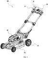
- a hand-powered self-driven traveling machine 100 comprises a chassis 10, a handle 20, wheels 30, a first motor 40, and a transmission mechanism 50.
- the hand-powered self-driven traveling machine 100 can also be called a power tool.
- the chassis 10 is used to mount the first motor 40.
- the wheels 30 are used to support the chassis 10. As the wheels 30 contact the ground and rotate around the first axis 102 relative to the chassis 10, the hand-powered self-driven traveling machine 100 rotate relative to the ground.
- the handle 20 is coupled to the chassis 10. Users can push the handle 20 to move the chassis 10 relative to the ground, thereby moving the hand-powered self-driven traveling machine 100 relative to the ground. Users can control the hand-powered self-driven traveling machine 100 by manipulating the handle 20.
- the first motor 40 comprises a motor shaft 41.
- the first motor 40 is to drive the wheels 30 to rotate.
- the motor shaft 41 is for outputting a driving force of the first motor 40 to the wheels 30.
- the motor shaft 41 rotates around a rotation axis 103 which is parallel to the first axis 102.
- the motor shaft 41 drives the wheels 30 to rotate.
- the first motor 40 is an electronic motor and the motor shaft 41 is an electronic motor shaft.
- the first motor 40 can also be called a self-propelling motor (a motor for propelling the hand-powered self-driven traveling machine to move by itself not external driving force).
- the hand-powered self-driven traveling machine 100 also comprises a battery pack that powers the first motor 40.
- the first motor 40 may also be an internal combustion engine powered by fuel combustion.
- the transmission mechanism 50 transmits power between the first motor 40 and the wheels 30.
- the transmission mechanism 50 connects the motor shaft 41 and the wheels 30 and transfers motion between the motor shaft 41 and the wheels 30.
- the transmission mechanism 50 transfers motion in one-way between the motor shaft 41 and the wheels 30.
- the transmission mechanism 50 drives the wheels 30 to rotate as the motor shaft 41 actively rotates.
- the wheels 30 actively rotate by a certain angle in any direction enables the wheels 30 freely rotate relative to the motor shaft 41.
- the transmission mechanism 50 comprises a clutch 50a.
- the clutch 50a has a drive state and an unlocked state. In the driving state, the motor shaft 41 drives the wheels 30 to rotate; in the unlocked state, the wheels 30 are free to rotate relative to the motor shaft 41.
- the hand-powered self-driven traveling machine 100 When the first motor 40 is in an off state where the first motor 40 does not drive the wheels 30 to rotate, the hand-powered self-driven traveling machine 100 is pushed to make the wheels 30 rotate by a certain angle in any direction, the clutch 50a turning to the unlocked state. That means the clutch 50a can be unlocked when the hand-powered self-driven traveling machine 100 is pushed forward or backward to rotate the wheels 30 clockwise or counterclockwise.
- the transmission mechanism 50 can realize the "unlocking” by rotating the wheels 30 in any direction, which is conveniently and quickly Operational.
- the hand-powered self-driven traveling machine 100 has a self-driving forward mode and a self-driving backward mode.
- the rotational speed of the wheels 30 is greater than that of the wheels 30 in the self-driving backward mode.
- the hand-powered self-driven traveling machine 100 comprises two start switches that respectively activate the machine for the self-driving forward mode and the self-driving backward mode.
- the hand-powered self-driven traveling machine 100 comprises a toggle switch that switches between the self-driving forward mode and the self-driving backward mode.
- the hand-powered self-driven traveling machine 100 has a manually-pushing state and a self-driving state.
- the hand-powered self-driven traveling machine 100 can be conveniently manually pushed forward or backward in the manually-pushing state and be propelled to travel by a motor instead of manual pushing force in the self-driving state.
- the hand-powered self-driven traveling machine 100 turns into the self-driving forward mode when pushed forward and turns into the self-driving backward mode when pushed backward.
- the hand-powered self-driven traveling machine 100 is provided with a switch that switches between the manually-pushing state and the self-driving state.
- the first motor 40 drives the wheels 30 to rotate in the first direction and in the self-drive back mode, drives the wheels 30 to rotate in the second direction opposite to the first direction.
- the clutch 50a turns into the unlocked state.
- the hand-powered self-driven traveling machine 100 can enter the manually-pushing state automatically, not by users' additional operations such as operating an unlock trigger or unlocking switch to unlock the clutch 50a.
- the clutch 50a turns into the unlocked state.
- the hand-powered self-driven traveling machine 100 can enter the manually-pushing state automatically, not by users' additional operations such as operating an unlock trigger or unlocking switch to unlock the clutch 50a.
- the self-propelling motor is turned off to make the hand-powered self-driven traveling machine 100 exit the self-driving forward mode means the self-propelling motor does not continue to drive the wheels 30 to rotate in the first direction.
- the self-propelling motor is turned off to make the hand-powered self-driven traveling machine 100 exit the self-driving backward mode means the self-propelling motor does not continue to drive the wheels 30 to rotate in the second direction.
- the hand-powered self-driven traveling machine 100 can enter the self-driving state and can also easily switch between the manually-pushing state and the self-driving state.
- the hand-powered self-driven traveling machine 100 When the first motor 40 is turned off to make the hand-powered self-driven traveling machine 100 exits the self-driving forward mode, the hand-powered self-driven traveling machine 100 is pushed backward to rotate the wheels 30 in the second direction and the clutch 50a turns into the unlocked state.
- the hand-powered self-driven traveling machine 100 When the first motor 40 is turned off to make the hand-powered self-driven traveling machine 100 exit the self-driving backward mode, the hand-powered self-driven traveling machine 100 is pushed forward to rotate the wheels 30 in the first direction and the clutch 50a turns into the unlocked state
- the first motor 40 When the hand-powered self-driven traveling machine 100 exits the self-driving forward mode, the first motor 40 is turned off.
- the clutch 50a can turn into the unlocked state when the hand-powered self-driven traveling machine 100 is pushed to drive the wheels 30 to rotate in any direction. That is, the clutch 50a can turn into the unlocked state when the hand-powered self-driven traveling machine 100 is pushed forward or backward to drive the wheels 30 to rotate in the first or second direction.
- the first motor 40 When the hand-powered self-driven traveling machine 100 exits the self-driving backward mode, the first motor 40 is turned off.
- the clutch 50a can turn into the unlocked state when the hand-powered self-driven traveling machine 100 is pushed to drive the wheels 30 to rotate in any direction. That is, the clutch 50a can turn into the unlocked state when the hand-powered self-driven traveling machine 100 is pushed forward or backward to drive the wheels 30 to rotate in the first or second direction.
- the hand-powered self-driven traveling machine 100 comprises a working element 70.
- the working element 70 is used to perform the functions of the hand-powered self-driven traveling machine 100.
- the working element 70 is a mowing blade and the hand-powered self-driven traveling machine 100 is a lawn mower.
- the chassis 10 forms a cutting cavity 11.
- the mowing blade rotates within the cutting cavity 11.
- the working element 70 is a snow-sweeping paddle and the hand-powered self-driven traveling machine 100 is a snow sweeper.
- the hand-powered self-driven traveling machine 100 comprises a second motor 60, and the second motor 60 is mounted to the chassis 10.
- the second motor 60 drives the working element 70.
- the second motor 60 can be an internal combustion engine powered by fuel combustion or a motor powered by electricity.
- the second motor 60 is an electronic motor.
- the battery pack supplies power to the second motor 60 and the first motor 40.
- the hand-powered self-driven traveling machine 100 comprises a power trigger 61 and a drive trigger 42.
- the power trigger 61 is used to activate the second motor 60 and the drive the trigger 42 is used to activate the first motor 40.
- the hand-powered self-driven traveling machine 100 can be a lawn mower and the second motor 60 can be called a mowing motor which drives the mowing blade to rotate.
- the mowing motor can also be called a mowing electric motor.
- the working element and the wheels can be driven by the same motor. That is, a motor, such as the first motor 40, drives the working element and also drives the wheels.
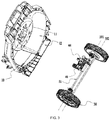
- a first wheel gear 31 is mounted and fixed to the wheels 30.
- the first wheel gear 31 is fixedly coupled to the wheels 30 to drive the wheels 30 to rotate.
- a second wheel gear 32 is mounted and fixed to the wheels 30.
- the first wheel gear 31 and second wheel gear 32 rotate in synchronization with the wheels 30.
- the hand-powered self-driven traveling machine 100 also comprises a wheel cover 33.
- the wheels 30 form a cavity in which the first wheel gear 31 and the second wheel gear 32 are located.
- the cavity is provided with an opening which is covered by the wheel cover 33 to prevent dust from entering the cavity to contaminate the first wheel gear 31 and the second wheel gear 32.
- the first wheel gear can also be a part of the wheels, that is to say, be formed with the wheels.
- the second wheel gear can also be a part of the wheels, that is to say, be formed with the wheels.
- the transmission mechanism 50 comprises the clutch 50a and a gearbox 80.
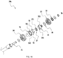
- the clutch 50a comprises a transmission shaft 51, a movable member 52, a driving paddle 53, and an outer ring member 56.
- the transmission shaft 51 is driven to rotate by the motor shaft 41 and then drive the wheels 30 to rotate.
- the gearbox 80 connects the transmission shaft 51 and the motor shaft 41 to make the motor shaft 41 drive the transmission shaft 51 to rotate and the rotation speed of the transmission shaft 51 is lower than the rotation speed of the motor shaft 41.
- the gearbox 80 comprises a first driving gear 81, a first driven gear 82, a second driving gear 83, a second driven gear 84, and an outer housing 85.
- the first driving gear 81 is fixed to the motor shaft 41.
- the first driven gear 82 meshes with the first driving gear 81.
- the first driven gear 82 and the second driving gear 83 rotate coaxially.
- the second driving gear 83 and the second driven gear 84 mesh with each other.
- the second driven gear 84 is fixed to the transmission shaft 51.
- the transmission mechanism 50 further comprises a first transmission gear 54, a second transmission gear 55, a fixing member 57, a friction member 58, and an elastic member 59.
- the first transmission gear 54 meshes with and rotates in synchronization with the first wheel gear 31.
- the transmission shaft 51 is driven to rotate and then drives the first transmission gear 54 to rotate, further drives the wheels 30 to rotate.
- the second transmission gear 55 meshes with and rotates in synchronization with the second wheel gear 32.
- the wheels 30 rotate, the first transmission gear 54 and the second transmission gear 55 rotate in opposite directions, and the second transmission gear 55 exerts a force opposite to the rotation direction of the first transmission gear 54 to the driving paddle 53.
- the first wheel gear 31 is an external gear
- the second wheel gear 32 is an internal gear
- the first transmission gear 54 is an external gear
- the second transmission gear 55 is an external gear.
- the transmission shaft 51 rotates about a central axis 101.
- the rotation axis 103 of the motor shaft is parallel to the central axis 101.
- the central axis 101 is parallel or coincident with the first axis 102.
- the first transmission gear 54 and the second transfer gear 55 rotate about the central axis 101.
- the rotational axis of the first transmission gear 54 coincides with the rotational axis of the second transmission gear 55 so that the transmission mechanism 50 is made compact.
- the movable member 52 can move between a locked position and an unlocked position relative to the transmission shaft 51.
- the movable member 52 is pins.
- the movable member 52 in Fig. 20 is in the locked position.
- the movable member 52 in Fig. 22 is in the unlocked position.
- the transmission shaft 51 drives the wheels 30 to rotate when the movable member 52 is in the locked position.
- the wheels 30 are free to rotate relative to the transmission shaft 51when the movable member 52 is in the unlocked position, that is, the transmission shaft 51 is not driven to rotate whether the wheels 30 rotate clockwise or counterclockwise.
- the driving paddle 53 is driven by the wheels 30 to make the movable member 52 move between the locked position and the unlocked position.
- the driving paddle 53 is driven by the wheels 30 to drive the movable member 52 move from the locked position to the unlocked position.
- the second transmission gear 55 when the wheels 30 rotate, the second transmission gear 55 is driven to rotate by the second wheel gear 32.
- the transmission between the second transmission gear 55 and the driving paddle 53 is friction transmission that the second transmission gear 55 drives the driving paddle 53 to move to make the movable member 52 move between the locked position and the unlocked position.
- the transmission between the wheels 30 and the driving paddle 53 is friction transmission.
- the wheels 30 exert a force opposite to the rotation direction of the first transmission gear 54 to the driving paddle 53.
- the friction member 58 realizing the friction transmission between the wheels 30 and the driving paddle 53, is disposed between the second transmission gear 55 and the driving paddle 53.
- the elastic member 59 exerts a force to the second transmission gear 55 to cause the driving paddle 53 and the second transmission gear 55 to clamp the friction member 58.
- the driving paddle 53 comprises a friction portion 532 which is in contact with the friction member 58 to transmit a frictional force.
- the second wheel gear, the second transmission gear and the friction member may not be removed and the wheels contact the driving paddle directly and exert a force opposite to the rotation direction of the first transmission gear to the driving paddle directly to realize the friction transmission between them.
- the fixing member 57 is coupled to and rotates in synchronization with the transmission shaft 51.
- the fixing member 57 forms a driving surface 571.
- the fixing member 57 is separately provided to help mount and remove the transmission mechanism 50.
- the transmission mechanism can also be provided without a fixing member, and the driving surface, as part of the transmission shaft, is formed with the transmission shaft.
- the outer ring member 56 is sleeved on the transmission shaft 51.
- the outer ring member 56 forms a mounting groove 561which accommodates the fixing member 57 and the movable member 52.
- the movable member 52 are pins.
- a plurality of pins are disposed in the mounting groove 561.
- the number of the driving surface is equivalent to the pin'.
- the pins are located between the groove wall 562, an annular surface, of the mounting groove 561 and the transmission shaft 51.
- the power tool comprises magnets 52a.
- the magnets 52a exert a magnetic attractive force to the movable member 52. Specifically, the magnets 52a exert an attractive force in the direction of the central axis 101 to the pins.
- the magnets 52a reduce the noise generated during the moving of the movable member 52.
- the magnets 52a make the movable member 52 less likely to topple or deflect during the movement to prevent the clutch 50a from being accidentally locked, keeping transmission reliable.
- the number of magnets 52a is equivalent to the pins'.
- a plurality of magnets 52a are evenly distributed in the circumferential direction of the central axis 101.
- each pin is subjected to the same force of the magnets, which keeps the transmission reliable.
- the magnets are annular.
- the power tool also comprises spacer 52b.
- the spacer 52b is located between the pins and the magnets 52a and disposed in the mounting groove 561.
- the spacer 52b enables the pin to move smoothly within the mounting groove 561.
- One end of the pin is in contact with the spacer 52b.
- the outer ring member 56 forms recesses 52c in which the magnets 52a are disposed.
- the outer ring member is located between the pins and the magnets in the direction of the central axis. That is, the magnets are disposed outside the mounting groove.
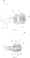
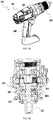
- the power tool 200 comprises a motor 201, a housing 202, and a work head 203.
- the motor 201 drives the working head 203 to rotate.
- the working head 203 is used to mount a working element.
- the housing 202 forms a handle 204 for users to hold.
- the power tool 200 comprises a clutch.
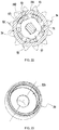
- the clutch comprises a transmission shaft 205, a driving paddle 206, an outer ring member 207, pins 208, and magnets 209.
- the driving paddle 206 comprises a plurality of paddle portions 2061.
- the driving paddle 206, the outer ring member 207 and the pins 208 respectively have the same structure and the same mounting way with the driving paddle, the outer ring member and the pins of the power tool shown in Fig. 1 to Fig. 24 .
- the power tools in Fig. 25 and Fig. 26 are hammer and drill tools.
- the clutch is also called shaft-lock structure.
- the clutch of Fig. 25 and Fig. 26 differs from the clutch of Fig. 1 to Fig. 24 in structure and mounting way of the magnets.
- the magnets 209 are annular and surround the transmission shaft 51.
- the magnets 209 are located outside the mounting groove and are fixed to the outer ring member 207.
- the outer ring member 207 is located between the pins and the magnets 209.
- the first transmission gear 54 is mounted to the outer ring member 56, and the outer ring member 56 drives the first transmission gear 54 to rotate.
- the movable member 52 is disposed between the driving surface 571 and the groove wall 562 of the mounting groove 561.
- the driving paddle 53 comprises a plurality of paddle portions 531. The paddle portions 531 get into the mounting groove 561 and contact with the movable member 52 to push the movable member 52 to move. A plurality of paddle portions 531 and a plurality of pins are alternatively arranged.
- the movable member 52 is in the locked position.
- the movable member 52 is simultaneously in contact with the groove wall 562 and the driving surface 571 of the mounting groove 561.
- the first motor 40 is working and the motor shaft 41 actively rotates.
- the transmission shaft 51 rotates in clockwise direction (the direction indicated by the arrow)
- the driving surface 571 drives the movable member 52 to rotate in clockwise direction for driving the outer ring member 56 and the first transmission gear 54 to rotate in clockwise direction, thereby driving the wheels 30 to rotate.
- the movable member 52 is located at a locked position capable of simultaneously contacting the driving surface 571 and the groove wall 562 of the mounting groove 561.
- the motor shaft 41 When the first motor 40 is working, the motor shaft 41 actively rotates, and at this time, the transmission shaft 51 rotates in clockwise direction (the direction indicated by the arrow).
- the movable member 52 simultaneously contacts the groove wall 562 of the mounting groove 561 and the driving surface 571. Thereby, the driving shaft 51 drives the outer ring member 56 to rotate clockwise.
- the first transmission gear 54 is sleeved on the outer ring member 56.
- the transmission between the first transmission gear 54 and the outer ring member 56 is realized through flat position.
- the clockwise rotation of the outer ring member 56 causes the first transmission gear 54 to rotate clockwise.
- the first transmission gear 54 meshes with the first wheel gear 31 to drive the wheels 30 to rotate.
- the driving paddle 53 receives a force, opposite to the rotation direction of the first transmission gear 54, from the wheels 30. That is, the driving paddle 53 receives a force in counterclockwise direction and is driven to the position shown in Fig. 20 by the wheels 30. At this time, the driving paddle 53 blocks the movement of the movable member 52, so that the movable member 52 cannot move from the locked position to the unlocked position, or the movable member 52 keeps in the locked position.
- the rotation of the wheels 30 drives the second transmission gear 55 to rotate counterclockwise. That is, the wheels 30 drives the second transmission gear 55 to rotate in a direction opposite to the rotation direction of the first transmission gear 54.
- the transmission between the second transmission gear 55 and the driving paddle 53 are friction transmission.
- the second transmission gear 55 exerts a force to the driving paddle 53 in a direction opposite to the rotation direction of the first transmission gear 54, and the driving paddle 53 is in the way of the movable member 52 from the locked position to the unlocked position.
- the driving paddle 53 is driven to rotate to the position shown in Fig. 20 by the wheels 30.
- the motor shaft 41 can drive the wheels 30 to rotate in the first direction to advance the machine.
- the hand-powered self-driven traveling machine 100 is in the self-driving forward mode.
- the wheels 30 actively rotate in a second direction opposite to the first direction and drive the first transmission gear 54 to rotate counterclockwise.
- the second transmission gear 55 rotates clockwise. The force exerted by the wheels 30 on the movable member 52 causes the movable member 52 to move from the locked position to the unlocked position.
- the wheels 30 can drive the driving paddle 53 to move, then the driving paddle 53 drives the movable member 52 move from the locked position to the unlocked position.
- the wheels 30 exert a clockwise force to the driving paddle 53.
- the transmission between the driving paddle 53 and the transmission shaft 51 is realized through flat position.
- the driving paddle 53 can rotate relative to the transmission shaft 51.
- the driving paddle 53 rotates by a certain angle under the force of the wheels 30, and pushes the movable member 52 to move from the locked position to the unlocked position.
- the hand-powered self-driven traveling machine 100 When the first motor 40 stops working, the hand-powered self-driven traveling machine 100 is pushed forward and the wheels 30 actively rotate, the wheels 30 drive the first transmission gear 54 to rotate clockwise.
- the first transmission gear 54 drives the outer ring member 56 to rotate clockwise.
- the outer ring member 56 rotates clockwise relative to the transmission shaft 51 to disengage the movable member 52 from the locked position.
- the driving paddle 53 can block the movable member 52 from entering the locked position on the other side. At this time, the movable member 52 cannot simultaneously contact the groove wall 562 of the mounting groove 561 and the driving surface 571.
- the outer ring member 56 is rotatable relative to the transmission shaft 51. That is, the wheels 30 are rotatable relative to the transmission shaft.
- the first motor 40 has a forward rotation mode and a reverse rotation mode.
- the motor shaft 41 rotates in the first direction; in the reverse mode, the motor shaft 41 rotates in the second direction opposite to the first direction. That is, the rotation directions of the motor shaft 41 are opposite in the forward rotation mode and the reverse rotation mode. More specifically, the current direction of the first motor 40 in the forward rotation mode is opposite to that in the reverse rotation mode.
- the motor shaft 41 of the first motor 40 enters the reverse rotation mode. The rotation direction of the motor shaft 41 is opposite to that in the self-driving state.
- the motor shaft 41 actively rotates by a certain angle to rotate the transmission shaft 51 by a certain angle so that the movable member 52 is moved from the locked position to the unlocked position to unlock the clutch.
- the hand-powered self-driven traveling machine 100 is stopped traveling suddenly by a large resistance in the self-driving state and the movable member 52 is in the locked position, there is a large static friction between the movable member 52 and the outer ring member 56, that is, the locking force of the movable member 52.
- the locking force of the movable member 52 is greater than the friction between the wheels 30 and the driving paddle 53, the wheels 30 cannot drive the driving paddle 53 to push the movable member 52 to move from the locked position to the unlocked position.
- the reverse rotation of the motor shaft 41 reduces the friction between the movable member 52 and the outer ring member 56 or directly moves the movable member 52 to the unlocked position.
- the movable member 52 can smoothly move to the unlocked position.
- the hand-powered self-driven traveling machine 100 can be pulled or pushed smoothly.
- the movable member 52 is located at an unlocked position where the movable member 52 cannot simultaneously contact the groove wall 562 of the mounting groove 561 and the driving surface 571.
- the transmission shaft 51 and the outer ring member 56 can freely rotate. That is, the transmission shaft 51 can freely rotate relative to the wheels 30.
- the wheels 30 rotate to drive the first transmission gear 54 and the outer ring member 56 to rotate in counterclockwise direction (the direction indicated by the arrow)
- the second transmission gear 55 is driven to rotate clockwise by the wheels 30. That is, the wheels 30 apply a force to the driving paddle 53 opposite to the rotation direction of the first transmission gear 54, and the driving paddle 53 is driven to rotate by the wheels 30 to the position shown in Fig. 22 .
- the driving paddle 53 blocks the movement of the movable member 52, preventing the movable member 52 from moving from the unlocked position to the locked position, keeping the movable member 52 in the unlocked position.
- the middle portion of the driving surface 571 corresponds to the unlocked position of the movable member 52, and two locked positions are respectively on the right and left side of the unlocked position.
- the movable member 52 in Fig. 20 is at the locked position on the left side.
- the motor shaft of the first motor 40 rotates in a direction to drive the transmission shaft 51 to rotate in the arrow direction, so that the hand-powered self-driven traveling machine 100 moves forward, that is, gets into the self-driving forward mode.
- the movable member 52 moves to the locked position on the right side, thereby realizing the backward movement, the self-driving backward mode, of the hand-powered self-driven traveling machine 100.
- the transmission principle and the unlocking principle of the clutch 50a are the same in the self-driving backward mode and the self-driving forward mode.
- the lawn mower comprises a motor shield 44.
- the motor shield 44 houses the self-propelling motor.
- the motor shield 44 comprises a motor guard portion 441 and a heat dissipating portion 442.
- the heat dissipating portion 442 protrudes from the motor guard portion 441 in a direction away from the ground.
- the motor guard portion 441 forms a motor cavity 4411 in which the self-propelling motor is located.
- the heat dissipating portion 442 forms a heat dissipating cavity 4421 connected through with the motor cavity 4411.
- the heat dissipating portion 442 is provided with heat dissipating hole 4422 which connects the heat dissipating cavity 4421 and the outside of the heat dissipating portion 442.
- the heat dissipating portion 442 can avoid reducing the heat dissipating effect by preventing the grass cuttings from blocking the heat dissipating holes 4422 or from entering the motor cavity 4411.
- the heat dissipating portion 442 protrudes from the motor guard portion 441 in the radial direction of the rotational axis 103 of the motor shaft.
- the heat dissipating portion 442 is connected to one end of the motor guard portion 441 in the axial direction of the rotational axis 103 of the motor shaft.
- the self-propelling motor further comprises a heat dissipating fan 43 fixed to the motor shaft.
- the motor guard portion 441 forms air hole 4412; and in the axial direction of the rotation axis 103 of the motor shaft, the position of the air hole 4412 corresponds to the position of the heat dissipating fan 43.
- the heat dissipating fan 43 rotates to drive air to flow into the motor shield 44 from the heat dissipating holes 4422 and be exhausted from the air hole 4412.
- the motor shield 44 forms two heat dissipating portions 442; the heat dissipating fan 43 is located between the two heat dissipating portions 442 in the axial direction of the rotational axis 103 of the motor shaft. In the axial direction of the rotational axis 103 of the motor shaft, the two heat dissipating portions 442 are respectively connected to the two ends of the motor guard portion 441.
- the motor guard portion 441 further forms auxiliary heat dissipating hole 4413, whose area is smaller than the area of the air hole 4412.
- the heat dissipating holes 4422 are formed in a strip shape; the long longitudinal direction of the strips coincides with the convex direction of the heat dissipating portion 442.
- the heat dissipating hole 4422 is located on side wall of the heat dissipating portion 442.
- the heat dissipating portion 442 forms auxiliary air hole 4423 located at the top end of the heat dissipating portion 442.
- the lawn mower also comprises an anti-wrapping sleeve 51a which is rotatably sleeved on the transmission shaft 51.
- the self-propelling motor drives the transmission shaft 51 to rotate about the central axis 101.
- the anti-wrapping sleeve 51a can prevent the transmission shaft 51 from being entangled by the grass when it rotates.
- the distance between the motor shield 44 and the anti-wrapping sleeve 51a is longer than 0 mm and shorter than or equal to 10 mm.
- the distance between the motor shield 44 and the anti-wrapping sleeve 51a is longer than 0 mm and shorter than or equal to 3 mm.
- the anti-wrapping sleeve 51a is disposed at one end of the gearbox 80.
- the anti-wrapping sleeve 51a and the self-propelling motor are located on the same side of the gearbox 80.
- An annular groove 851 is formed between the outer housing 85 and the transmission shaft 51.
- One end of the anti-wrapping sleeve 51a is located in the annular groove 851.
- the anti-wrapping sleeve 51a defines a large end 511a and a small end 511b.
- the diameter of the large end 511a is larger than that of the small end 511b.
- the large end 511a of the anti-wrap 51a is closer to the gearbox 80 than the small end 511b.
- the large end 511a of the anti-wrapping sleeve 51a is located in the annular groove 851.
- the transmission shaft 51 extends through the gearbox 80.
- the chassis 10 forms a motor housing cavity 12 in which the self-propelling motor is located.
- the opening of the motor housing cavity 12 coincides with that of the cutting cavity 11, and the opening of the motor housing cavity 12 is towards the ground.
- the anti-wrap 51a is located between the gearbox 80 and the wall of the motor housing cavity 12.
Landscapes
- Engineering & Computer Science (AREA)
- Life Sciences & Earth Sciences (AREA)
- Environmental Sciences (AREA)
- General Engineering & Computer Science (AREA)
- Mechanical Engineering (AREA)
- Architecture (AREA)
- Civil Engineering (AREA)
- Structural Engineering (AREA)
- Transportation (AREA)
- Combustion & Propulsion (AREA)
- Chemical & Material Sciences (AREA)
- Physics & Mathematics (AREA)
- Electromagnetism (AREA)
- Harvester Elements (AREA)
- Arrangement Of Transmissions (AREA)
- Handcart (AREA)
- Toys (AREA)
- Electric Propulsion And Braking For Vehicles (AREA)
- Electric Suction Cleaners (AREA)
- Mechanical Operated Clutches (AREA)
Abstract
Description
- The present invention relates to a hand-powered self-driven traveling machine.
- Lawn mowers, snowplows, etc. are common hand-powered self-driven traveling machines. The hand-powered self-driven traveling machine comprises a motor, wheels, and a transmission mechanism. The motor drives the wheels to rotate through the transmission mechanism so that the hand-powered self-driven traveling machine moves relative to the ground.
- The hand-powered self-driven traveling machine requires the right wheel and the left wheel to rotate at different speeds during steering. The conventional hand-powered self-driven traveling machine is provided with a clutch to enable the right wheel and the left wheel to rotate asynchronously. Specifically, the rotation speed of a wheel is greater than the other wheel's. The clutch is also called a differential. For the conventional hand-powered self-driven machine with that clutch, when the motor shaft stops rotating, the machine can be pushed forward to make the wheels continue to rotate forward, and the clutch can cut off the transmission between the wheels and the motor shaft. When the motor stops rotating and the machine is pulled backward to rotate the wheel backward, the clutch cannot disconnect the transmission between the wheels and the motor shaft, and the wheels will drive the motor shaft to rotate. At this point where the differential is in a driving state, a large force is required to pull the hand-powered self-driven traveling machine to move backward, which is known as the "lock-up" phenomenon. After the motor stops rotating, in order to disconnect the transmission between the wheels and the motor shaft and in order to make the differential into an unlocked state, the machine needs to be pushed forward to unlock differential, then the wheels can rotate freely relative to the motor shaft. Pulling the hand-powered self-driven traveling machine backward cannot make the machine "unlocked", which brings great inconvenience to users.
- After the motor stops and when the machine is pushed or is pulled, the wheels will rotate and drive the motor shaft to rotate through the transmission mechanism. In that condition, a great force is required to push or pull the machine to move.
- A hand-powered self-driven traveling machine, comprising a chassis, a handle, wheels, a first motor, a working element, a second motor, and a transmission mechanism. The handle is connected to the chassis. The wheels are for supporting the chassis and can rotate relative to the chassis. The first motor is mounted to the chassis, for providing driving force of rotating the wheels. The working element moves relative to the chassis to implement the machine's function. The second motor is for driving the working element to move. The transmission mechanism connects the first motor with the wheels and comprises a clutch for realizing one-way transmission between the first motor and the wheels, wherein the clutch has a driving state where the first motor drives the wheels to rotate and an unlocked state where the wheels freely rotate relative to the first motor. The clutch comprises a movable member and a driving paddle. The movable member is capable of moving between a locked position and an unlocked position. The driving paddle transfers power with the wheels by means of friction. When the movable member is in the locked position, the clutch is in the driving state where the first motor is capable of driving the wheels to rotate in a first direction. When the movable member is in the unlocked position the clutch is in the unlocked state. When the first motor stops rotating, the wheels rotate in a second direction opposite to the first direction, and can drive the driving paddle to move so that the driving paddle pushes the movable member to move from the locked position to the unlocked position.
- In one or more embodiments, the first motor comprises a motor shaft for outputting driving force. The clutch comprises a transmission shaft, a fixing member and an outer ring member. The transmission shaft is connected to the motor shaft and is driven by the motor shaft to rotate. The fixing member is coupled to the transmission shaft or is a part of the transmission shaft and forms a driving surface capable of driving the movable member. The outer ring member is sleeved on the transmission shaft, is connected to the wheels to drive the wheels to rotate and forms a mounting groove. The movable member is located between the wall of the mounting groove and the driving surface.
- In one or more embodiments, the wall of the mounting groove is an annular surface, and the movable member is a pin.
- In one or more embodiments, the driving paddle comprises a plurality of paddle portions, and the paddle portions get into the mounting groove and are capable of contacting the movable member to push the movable member to move.
- In one or more embodiments, the clutch comprises a plurality of movable members and the number of the movable members is the same as the paddle portions'. The paddle portions and the movable members are alternatively arranged.
- In one or more embodiments, the fixing member forms a plurality of driving surfaces and the number of the driving surfaces is the same as the movable members', the driving surfaces are in one-to-one correspondence with the movable members.
- In one or more embodiments, the frictional force between the wheels and the driving paddle is greater than the frictional force between the fixing member and the movable member when the movable member is in the locked position.
- In one or more embodiments, the wheels form a first wheel gear or a first wheel gear is mounted on the wheels. The hand-powered self-driven traveling machine further comprises a first transmission gear meshing with the first wheel gear and driven by the transmission shaft to drive the wheel to rotate. When the motor shaft actively rotates, the transmission shaft drives the first transmission gear to rotate so as to rotate the wheels and the wheels exert a force, whose direction is opposite to the rotation direction of the first transmission gear, to the driving paddle.
- In one or more embodiments, the wheels form a second wheel gear or a second wheel gear is mounted on the wheels. The hand-powered self-driven traveling machine further comprises a second transmission gear meshing with the second wheel gear. When the wheels rotates, the first transmission gear and the second transmission gear rotate in opposite directions and the second transmission gear exerts a force, whose direction is opposite to the rotation direction of the first transmission gear, to the driving paddle.
- In one or more embodiments, the hand-powered self-driven traveling machine further comprises a friction plate disposed between the second transmission gear and the driving paddle and realizing the friction transmission between the second transmission gear and the driving paddle.
- In one or more embodiments, the clutch comprises a magnet exerting a magnetic attractive force to the movable member.
- In one or more embodiments, the clutch comprises a plurality of the movable members and the magnets, whose number is equivalent to the number of the movable members. The transmission shaft rotates about a central axis, in the direction of which magnets exert a magnetic attractive force to the movable members of the central axis.
- In one or more embodiments, the magnets are fixed to the outer ring member and are evenly distributed in the circumferential direction of the central axis.
- In one or more embodiments, the magnet is annular and surrounds the transmission shaft.
- A hand-powered self-driven traveling machine, comprising a chassis, a working element, a handle, wheels, a motor and a clutch. The working element moves relative to the chassis to implement the machine's function. The handle is connected to the chassis. The wheels are for supporting the chassis and can rotate relative to the chassis. The motor is capable of providing driving force of rotating the wheels and comprising a motor shaft for outputting driving force. The clutch is capable of one-way transmitting between the motor shaft and the wheels. The clutch has a driving state where the motor shaft drives the wheels to rotate and an unlocked state where the wheels freely rotate relative to the motor shaft. The clutch comprises a movable member and a driving paddle. The movable member is capable of moving between a locked position and an unlocked position. The driving paddle could be driven by the wheels. When the movable member is in the locked position the clutch is in the driving state where the motor shaft drives the wheels to rotate in a first direction. When the movable member is in the unlocked position the clutch is in the unlocked state. When the motor shaft stops rotating, the wheels rotate in a second direction opposite to the first direction and can drive the driving paddle to move so that the driving paddle pushes the movable member to move from the locked position to the unlocked position.
- In one or more embodiments, the wheels drive the driving paddle by friction.
- In one or more embodiments, the clutch comprises a transmission shaft, a fixing member and an outer ring member. The transmission shaft is coupled to the motor shaft and is driven to rotate by the motor shaft. The fixing member is coupled to the transmission shaft or is a part of the transmission shaft and forms a driving surface capable of driving the movable member. The outer ring member is sleeved on the transmission shaft and is connected to the wheels to drive the wheels to rotate. The outer ring member forms a mounting groove between the wall of which and the driving surface the movable member is located.
- In one or more embodiments, the wall of the mounting groove is an annular surface, and the movable member is a pin.
- In one or more embodiments, the driving paddle comprises a plurality of paddle portions, and the paddle portions get into the mounting groove and are capable of contacting the movable member to push the movable member to move.
- In one or more embodiments, the clutch comprises a plurality of movable members and the number of the movable members is equivalent to the paddle portions'. The paddle portions and the movable members are alternatively arranged.
- In one or more embodiments, the fixing member forms a plurality of driving surfaces and the number of the driving surfaces is the same as the movable members', the driving surfaces are in one-to-one correspondence with the movable members.
- In one or more embodiments, the wheels form a first wheel gear or a first wheel gear is mounted on the wheels, and the hand-powered self-driven traveling machine further comprises a first transmission gear meshing with the first wheel gear and driven by the transmission shaft to drive the wheel to rotate. When the motor shaft actively rotates, the transmission shaft drives the first transmission gear to rotate, thereby driving the wheels to rotate and the wheels exerting a force, whose direction is opposite to the rotation direction of the first transmission gear, to the driving paddle.
- In one or more embodiments, the wheels form a second wheel gear or a second wheel gear is mounted on the wheels, and the hand-powered self-driven traveling machine further comprises a second transmission gear meshing with the second wheel gear. When the wheels rotates, the first transmission gear and the second transmission gear rotate in opposite directions and the second transmission gear exerts a force whose direction is opposite to the rotation direction of the first transmission gear to the driving paddle.
- In one or more embodiments, the hand-powered self-driven traveling machine further comprises a friction plate disposed between the second transmission gear and the driving paddle and realizing the friction transmission between the second transmission gear and the driving paddle.
- In one or more embodiments, the hand-powered self-driven traveling machine has a self-driven forward-moving mode in which the motor drives the wheels to rotate in the first direction and a self-driven backward-moving mode. When the motor is turned off, the hand-powered self-driven traveling machine is out of the self-driven forward-moving mode and the hand-powered self-driven traveling machine is pushed forward to make the wheels rotate in the first direction, the wheels drive the movable member to move from the locked position to the unlocked position and the clutch turns into the unlocked state. When the hand-powered self-driven traveling machine is in the self-driven backward-moving mode, the motor drives the wheels to rotate in the second direction opposite to the first direction. When the motor is turned off, the hand-powered self-driven traveling machine is out of the self-driven backward-moving mode and the hand-powered self-driven traveling machine is pushed to make the wheels rotate in the second direction, the wheels drive the movable member to move from the locked position to the unlocked position and the clutch into the unlocked state.
- In one or more embodiments, when the motor is turned off, the hand-powered self-driven traveling machine is out of the self-driven forward-moving mode and the hand-powered self-driven traveling machine is pushed backward to make the wheels rotate in the second direction, the wheels drive the movable member to move from the locked position to the unlocked position and the clutch turns into the unlocked state. When the motor is turned off , the hand-powered self-driven traveling machine is out of the self-driven backward-moving mode and the hand-powered self-driven traveling machine is pushed forward to make the wheels rotate in the first direction , the wheels drive the movable member to move from the locked position to the unlocked position and the clutch turns into the unlocked state.
- In one or more embodiments, the hand-powered self-driven traveling machine has a self-driven forward-moving mode in which the motor drives the wheels to rotate in the first direction and a self-driven backward-moving mode in which the motor drives the wheels to rotate in the second direction opposite to the first direction. when the motor is turned off and the hand-powered self-driven traveling machine is pushed to drive the wheels to turn at an angle in any direction, the wheels drive the movable member to move from the locked position to the unlocked position and the clutch turns into the unlocked state.
- In one or more embodiments, the hand-powered self-driven traveling machine further comprises a transmission mechanism connecting the motor shaft and the wheels; wherein the transmission mechanism comprises the clutch and a gearbox connecting the motor shaft and the clutch.
- In one or more embodiments, the clutch comprises a magnet exerting a magnetic attractive force to the movable member.
- In one or more embodiments, the clutch comprises a plurality of the movable members and the magnets, whose number is the same as the magnets' and the transmission shaft rotates about a central axis, in the direction of which magnets exert a magnetic attractive force to the movable members of the central axis.
- In one or more embodiments, the magnets are fixed to the outer ring member and are evenly distributed in the circumferential direction of the central axis.
- In one or more embodiments, the magnet is annular and surrounds the transmission shaft.
- In one or more embodiments, the working element is driven to move by the motor.
- In one or more embodiments, the hand-powered self-driven traveling machine further comprises a second motor for driving the working element to move.
- A hand-powered self-driven traveling machine, comprising a chassis, a handle, wheels, a motor, and a transmission mechanism. The handle is connected to the chassis. The wheels are for supporting the chassis and capable of rotating relative to the chassis. The motor is capable of providing driving force of rotating the wheels. The transmission mechanism connects the motor with the wheels and comprises a clutch for realizing one-way transmission between the motor and the wheels. The clutch has a driving state where the motor drives the wheels to rotate and an unlocked state where the wheels freely rotate relative to the motor. the clutch comprises a movable member capable of moving between a locked position and an unlocked position. When the movable member is in the locked position the clutch is in the driving state where the motor actively rotates to drive the wheels to rotate. When the movable member is in the unlocked position the clutch is in the unlocked state. When the motor stops rotating, the wheels rotate at an angle in any direction and drive the movable member to move from the locked position to the unlocked position.
- In one or more embodiments, the clutch further comprises a driving paddle. When the clutch is in the driving state, the motor can drive the wheels to rotate in a first direction. When the motor stops rotating, the wheels rotate in a second direction opposite to the first direction, and can drive the driving paddle to move so that the driving paddle pushes the movable member to move from the locked position to the unlocked position.
- In one or more embodiments, the wheels can drive the driving paddle to move by friction force.
- In one or more embodiments, the motor comprises a motor shaft for outputting driving force. The clutch comprises a transmission shaft, a fixing member and an outer ring member. The transmission shaft is connected to the motor shaft and is driven by the motor shaft to rotate. The fixing member is coupled to the transmission shaft or is a part of the transmission shaft and forms a driving surface capable of driving the movable member. The outer ring member is sleeved on the transmission shaft, is connected to the wheels to drive the wheel to rotate. and forms a mounting groove. The movable member is located between the wall of the mounting groove and the driving surface.
- In one or more embodiments, the wall of the mounting groove is an annular surface, and the movable member is a pin.
- In one or more embodiments, the wheels form a first wheel gear or a first wheel gear is mounted on the wheels. The hand-powered self-driven traveling machine further comprises a first transmission gear meshing with the first wheel gear and driven by the transmission shaft to drive the wheels to rotate. When the motor shaft actively rotates, the transmission shaft drives the first transmission gear to rotate so as to rotate the wheels and the wheels exert a force, whose direction is opposite to the rotation direction of the first transmission gear, to the driving paddle.
- In one or more embodiments, the wheels form a second wheel gear or a second wheel gear is mounted on the wheels. The hand-powered self-driven traveling machine further comprises a second transmission gear meshing with the second wheel gear. When the wheels rotates, the first transmission gear and the second transmission gear rotate in opposite directions and the second transmission gear exerts a force, whose direction is opposite to the rotation direction of the first transmission gear, to the driving paddle.
- In one or more embodiments, the hand-powered self-driven traveling machine further comprises a friction plate disposed between the second transmission gear and the driving paddle to realize the friction transmission between the second transmission gear and the driving paddle.
- In one or more embodiments, the hand-powered self-driven traveling machine has a self-driven forward mode and a self-driven backward mode. When the hand-powered self-driven traveling machine is in the self-driven forward mode, the motor drives the wheels to rotate in the first direction. When the motor is turned off, the hand-powered self-driven traveling machine is out of the self-driven forward mode and the hand-powered self-driven traveling machine is pushed forward to make the wheels rotate in the first direction, the wheels drive the movable member to move from the locked position to the unlocked position and the clutch gets into the unlocked state. When the hand-powered self-driven traveling machine is in the self-driven backward mode, the motor drives the wheels to rotate in the second direction opposite to the first direction. When the motor is turned off,the hand-powered self-driven traveling machine is out of the self-driven backward mode and the hand-powered self-driven traveling machine is pushed backward to make the wheels rotate in the second direction, the wheels drive the movable member to move from the locked position to the unlocked position and the clutch gets into the unlocked state.
- In one or more embodiments, when the motor is turned off, the hand-powered self-driven traveling machine is out of the self-driven forward-moving mode and the hand-powered self-driven traveling machine is pushed backward to make the wheels rotate in the second direction, the wheels drive the movable member to move from the locked position to the unlocked position and the clutch turns into the unlocked state. When the motor is turned off, the hand-powered self-driven traveling machine is out of the self-driven backward-moving mode and the hand-powered self-driven traveling machine is pushed forward to make the wheels rotate in the first direction, the wheels drive the movable member to move from the locked position to the unlocked position and the clutch turns into the unlocked state.
- In one or more embodiments, the hand-powered self-driven traveling machine has a self-driven forward-moving mode in which the motor drives the wheels to rotate in the first direction and a self-driven backward-moving mode in which the motor drives the wheels to rotate in the second direction opposite to the first direction. When the motor is turned off, the hand-powered self-driven traveling machine could be pushed to drive the wheels to turn at an angle in any direction and the wheels drive the movable member to move from the locked position to the unlocked position, the clutch turning into the unlocked state.
-
-
Figure 1 is a perspective view of the hand-powered self-driven traveling machine; -
Figure 2 is a schematic view of the chassis, motor, transmission mechanism and wheels of the hand-powered self-driven traveling machine ofFigure 1 ; -
Figure 3 is a schematic view of the transmission mechanism separated from the chassis ofFigure 2 ; -
Figure 4 is a schematic view of the motor protection shield located in the motor receiving slot ofFigure 2 ; -
Figure 5 is a schematic view of the anti-wrap and gearbox ofFigure 4 ; -
Figure 6 is a schematic view of the motor protection shield of the hand-powered self-driven traveling machine ofFigure 1 ; -
Figure 7 is a schematic view of another perspective of the structure ofFigure 6 ; -
Figure 8 is a cross-sectional view of the structure ofFigure 6 ; -
Figure 9 is an exploded view of the structure ofFigure 6 ; -
Figure 10 is a schematic view showing the internal structure of the gearbox of the hand-powered self-driven traveling machine ofFigure 1 ; -
Figure 11 is a schematic view of the motor, the transmission mechanism and the wheels of the hand-powered self-driven traveling machine ofFigure 1 ; -
Figure 12 is a schematic view of the structure ofFigure 11 after removing the wheel cover; -
Figure 13 is a schematic view showing the first transmission gear and the second transmission gear of the transmission mechanism ofFig. 12 respectively engaged with the first wheel gear and the second wheel gear; -
Figure 14 is a schematic view of the transmission mechanism ofFigure 13 ; -
Figure 15 is a cross-sectional view of the transmission mechanism ofFigure 14 ; -
Figure 16 is an exploded view of the transmission mechanism ofFigure 14 ; -
Figure 17 is an exploded view of another perspective of the transmission mechanism ofFigure 14 ; -
Figure 18 is a schematic view of the first transmission gear, the outer ring member and the driving paddle of the transmission mechanism ofFigure 14 ; -
Figure 19 is a plan view of another perspective of the structure ofFigure 18 ; -
Figure 20 is a cross-sectional view of the structure ofFigure 18 along line A-A; -
Figure 21 is a cross-sectional view of the structure ofFigure 18 along line B-B; -
Figure 22 is a schematic view of the movable member ofFigure 20 in an unlocked position; -
Figure 23 is a schematic view of the outer ring member, the magnet and the spacer of -
Figure 16 ; -
Figure 24 is an exploded view of the structure ofFigure 23 ; -
Figure 25 is a schematic view of another power tool; -
Figure 26 is a schematic illustration of the transmission shaft, the outer ring member, the pin and the magnet of the power tool ofFigure 25 . - As shown in
Fig. 1 to Fig. 3 , a hand-powered self-driven travelingmachine 100 comprises achassis 10, ahandle 20,wheels 30, afirst motor 40, and atransmission mechanism 50. The hand-powered self-driven travelingmachine 100 can also be called a power tool. - The
chassis 10 is used to mount thefirst motor 40. Thewheels 30 are used to support thechassis 10. As thewheels 30 contact the ground and rotate around thefirst axis 102 relative to thechassis 10, the hand-powered self-driven travelingmachine 100 rotate relative to the ground. Thehandle 20 is coupled to thechassis 10. Users can push thehandle 20 to move thechassis 10 relative to the ground, thereby moving the hand-powered self-driven travelingmachine 100 relative to the ground. Users can control the hand-powered self-driven travelingmachine 100 by manipulating thehandle 20. - The
first motor 40 comprises amotor shaft 41. Thefirst motor 40 is to drive thewheels 30 to rotate. Themotor shaft 41 is for outputting a driving force of thefirst motor 40 to thewheels 30. Themotor shaft 41 rotates around arotation axis 103 which is parallel to thefirst axis 102. Themotor shaft 41 drives thewheels 30 to rotate. As a specific embodiment, thefirst motor 40 is an electronic motor and themotor shaft 41 is an electronic motor shaft. Thefirst motor 40 can also be called a self-propelling motor (a motor for propelling the hand-powered self-driven traveling machine to move by itself not external driving force). The hand-powered self-driven travelingmachine 100 also comprises a battery pack that powers thefirst motor 40. As an alternative embodiment, thefirst motor 40 may also be an internal combustion engine powered by fuel combustion. - The
transmission mechanism 50 transmits power between thefirst motor 40 and thewheels 30. Thetransmission mechanism 50 connects themotor shaft 41 and thewheels 30 and transfers motion between themotor shaft 41 and thewheels 30. - Specifically, the
transmission mechanism 50 transfers motion in one-way between themotor shaft 41 and thewheels 30. Thetransmission mechanism 50 drives thewheels 30 to rotate as themotor shaft 41 actively rotates. Thewheels 30 actively rotate by a certain angle in any direction enables thewheels 30 freely rotate relative to themotor shaft 41. Thetransmission mechanism 50 comprises a clutch 50a. The clutch 50a has a drive state and an unlocked state. In the driving state, themotor shaft 41 drives thewheels 30 to rotate; in the unlocked state, thewheels 30 are free to rotate relative to themotor shaft 41. - When the
first motor 40 is in an off state where thefirst motor 40 does not drive thewheels 30 to rotate, the hand-powered self-driven travelingmachine 100 is pushed to make thewheels 30 rotate by a certain angle in any direction, the clutch 50a turning to the unlocked state. That means the clutch 50a can be unlocked when the hand-powered self-driven travelingmachine 100 is pushed forward or backward to rotate thewheels 30 clockwise or counterclockwise. - The
transmission mechanism 50 can realize the "unlocking" by rotating thewheels 30 in any direction, which is conveniently and quickly Operational. - The hand-powered self-driven traveling
machine 100 has a self-driving forward mode and a self-driving backward mode. In the self-driving forward mode, the rotational speed of thewheels 30 is greater than that of thewheels 30 in the self-driving backward mode. - As an alternative embodiment, the hand-powered self-driven traveling
machine 100 comprises two start switches that respectively activate the machine for the self-driving forward mode and the self-driving backward mode. - As another alternative embodiment, the hand-powered self-driven traveling
machine 100 comprises a toggle switch that switches between the self-driving forward mode and the self-driving backward mode. - The hand-powered self-driven traveling
machine 100 has a manually-pushing state and a self-driving state. The hand-powered self-driven travelingmachine 100 can be conveniently manually pushed forward or backward in the manually-pushing state and be propelled to travel by a motor instead of manual pushing force in the self-driving state. - As an alternative embodiment, the hand-powered self-driven traveling
machine 100 turns into the self-driving forward mode when pushed forward and turns into the self-driving backward mode when pushed backward. As an alternative specific embodiment, the hand-powered self-driven travelingmachine 100 is provided with a switch that switches between the manually-pushing state and the self-driving state. - In the self-driving forward mode, the
first motor 40 drives thewheels 30 to rotate in the first direction and in the self-drive back mode, drives thewheels 30 to rotate in the second direction opposite to the first direction. - When the
first motor 40 is turned off to make the hand-powered self-driven travelingmachine 100 exit the self-driving forward mode and the hand-powered self-driven travelingmachine 100 is pushed forward to rotate thewheels 30 in the first direction, the clutch 50a turns into the unlocked state. The hand-powered self-driven travelingmachine 100 can enter the manually-pushing state automatically, not by users' additional operations such as operating an unlock trigger or unlocking switch to unlock the clutch 50a. - When the self-propelling motor is turned off to make the hand-powered self-driven traveling
machine 100 exit the self-driving backward mode and the hand-powered self-driven travelingmachine 100 is pushed backward to rotate thewheels 30 in the second direction, the clutch 50a turns into the unlocked state. The hand-powered self-driven travelingmachine 100 can enter the manually-pushing state automatically, not by users' additional operations such as operating an unlock trigger or unlocking switch to unlock the clutch 50a. The self-propelling motor is turned off to make the hand-powered self-driven travelingmachine 100 exit the self-driving forward mode means the self-propelling motor does not continue to drive thewheels 30 to rotate in the first direction. The self-propelling motor is turned off to make the hand-powered self-driven travelingmachine 100 exit the self-driving backward mode means the self-propelling motor does not continue to drive thewheels 30 to rotate in the second direction. - After the
first motor 40 is turned on, the hand-powered self-driven travelingmachine 100 can enter the self-driving state and can also easily switch between the manually-pushing state and the self-driving state. - When the
first motor 40 is turned off to make the hand-powered self-driven travelingmachine 100 exits the self-driving forward mode, the hand-powered self-driven travelingmachine 100 is pushed backward to rotate thewheels 30 in the second direction and the clutch 50a turns into the unlocked state. When thefirst motor 40 is turned off to make the hand-powered self-driven travelingmachine 100 exit the self-driving backward mode, the hand-powered self-driven travelingmachine 100 is pushed forward to rotate thewheels 30 in the first direction and the clutch 50a turns into the unlocked state - When the hand-powered self-driven traveling
machine 100 exits the self-driving forward mode, thefirst motor 40 is turned off. The clutch 50a can turn into the unlocked state when the hand-powered self-driven travelingmachine 100 is pushed to drive thewheels 30 to rotate in any direction. That is, the clutch 50a can turn into the unlocked state when the hand-powered self-driven travelingmachine 100 is pushed forward or backward to drive thewheels 30 to rotate in the first or second direction. - When the hand-powered self-driven traveling
machine 100 exits the self-driving backward mode, thefirst motor 40 is turned off. The clutch 50a can turn into the unlocked state when the hand-powered self-driven travelingmachine 100 is pushed to drive thewheels 30 to rotate in any direction. That is, the clutch 50a can turn into the unlocked state when the hand-powered self-driven travelingmachine 100 is pushed forward or backward to drive thewheels 30 to rotate in the first or second direction. - The hand-powered self-driven traveling
machine 100 comprises a workingelement 70. The workingelement 70 is used to perform the functions of the hand-powered self-driven travelingmachine 100. As a specific embodiment, the workingelement 70 is a mowing blade and the hand-powered self-driven travelingmachine 100 is a lawn mower. Thechassis 10 forms a cuttingcavity 11. The mowing blade rotates within the cuttingcavity 11. As another embodiment, the workingelement 70 is a snow-sweeping paddle and the hand-powered self-driven travelingmachine 100 is a snow sweeper. - As a specific embodiment, the working
element 70 and thewheels 30 are respectively driven by different motors. Specifically, the hand-powered self-driven travelingmachine 100 comprises asecond motor 60, and thesecond motor 60 is mounted to thechassis 10. Thesecond motor 60 drives the workingelement 70. Thesecond motor 60 can be an internal combustion engine powered by fuel combustion or a motor powered by electricity. Specifically, thesecond motor 60 is an electronic motor. The battery pack supplies power to thesecond motor 60 and thefirst motor 40. As shown inFig. 1 , the hand-powered self-driven travelingmachine 100 comprises apower trigger 61 and adrive trigger 42. Thepower trigger 61 is used to activate thesecond motor 60 and the drive thetrigger 42 is used to activate thefirst motor 40. The hand-powered self-driven travelingmachine 100 can be a lawn mower and thesecond motor 60 can be called a mowing motor which drives the mowing blade to rotate. When the mowing motor is powered by electricity, the mowing motor can also be called a mowing electric motor. - As an alternative embodiment, the working element and the wheels can be driven by the same motor. That is, a motor, such as the
first motor 40, drives the working element and also drives the wheels. - As shown in
Fig. 11 to Fig. 13 , afirst wheel gear 31 is mounted and fixed to thewheels 30. Thefirst wheel gear 31 is fixedly coupled to thewheels 30 to drive thewheels 30 to rotate. Asecond wheel gear 32 is mounted and fixed to thewheels 30. Thefirst wheel gear 31 andsecond wheel gear 32 rotate in synchronization with thewheels 30. The hand-powered self-driven travelingmachine 100 also comprises awheel cover 33. Thewheels 30 form a cavity in which thefirst wheel gear 31 and thesecond wheel gear 32 are located. The cavity is provided with an opening which is covered by thewheel cover 33 to prevent dust from entering the cavity to contaminate thefirst wheel gear 31 and thesecond wheel gear 32. - As another embodiment, the first wheel gear can also be a part of the wheels, that is to say, be formed with the wheels. The second wheel gear can also be a part of the wheels, that is to say, be formed with the wheels.
- The
transmission mechanism 50 comprises the clutch 50a and agearbox 80. As shown inFig. 12 to Fig. 17 , the clutch 50a comprises atransmission shaft 51, amovable member 52, a drivingpaddle 53, and anouter ring member 56. - The
transmission shaft 51 is driven to rotate by themotor shaft 41 and then drive thewheels 30 to rotate. Thegearbox 80 connects thetransmission shaft 51 and themotor shaft 41 to make themotor shaft 41 drive thetransmission shaft 51 to rotate and the rotation speed of thetransmission shaft 51 is lower than the rotation speed of themotor shaft 41. As shown inFig. 9 andFig. 10 , thegearbox 80 comprises afirst driving gear 81, a first drivengear 82, asecond driving gear 83, a second drivengear 84, and anouter housing 85. Thefirst driving gear 81 is fixed to themotor shaft 41. The first drivengear 82 meshes with thefirst driving gear 81. The first drivengear 82 and thesecond driving gear 83 rotate coaxially. Thesecond driving gear 83 and the second drivengear 84 mesh with each other. The second drivengear 84 is fixed to thetransmission shaft 51. - As shown in
Fig. 12 to Fig. 19 , thetransmission mechanism 50 further comprises afirst transmission gear 54, asecond transmission gear 55, a fixingmember 57, afriction member 58, and anelastic member 59. - The
first transmission gear 54 meshes with and rotates in synchronization with thefirst wheel gear 31. When thefirst motor 40 is working or themotor shaft 41 rotates actively, thetransmission shaft 51 is driven to rotate and then drives thefirst transmission gear 54 to rotate, further drives thewheels 30 to rotate. Thesecond transmission gear 55 meshes with and rotates in synchronization with thesecond wheel gear 32. When thewheels 30 rotate, thefirst transmission gear 54 and thesecond transmission gear 55 rotate in opposite directions, and thesecond transmission gear 55 exerts a force opposite to the rotation direction of thefirst transmission gear 54 to the drivingpaddle 53. - Specifically, the
first wheel gear 31 is an external gear, thesecond wheel gear 32 is an internal gear, thefirst transmission gear 54 is an external gear, and thesecond transmission gear 55 is an external gear. Thetransmission shaft 51 rotates about acentral axis 101. Therotation axis 103 of the motor shaft is parallel to thecentral axis 101. Thecentral axis 101 is parallel or coincident with thefirst axis 102. Thefirst transmission gear 54 and thesecond transfer gear 55 rotate about thecentral axis 101. The rotational axis of thefirst transmission gear 54 coincides with the rotational axis of thesecond transmission gear 55 so that thetransmission mechanism 50 is made compact. - The
movable member 52 can move between a locked position and an unlocked position relative to thetransmission shaft 51. Specifically, themovable member 52 is pins. Themovable member 52 inFig. 20 is in the locked position. Themovable member 52 inFig. 22 is in the unlocked position. Thetransmission shaft 51 drives thewheels 30 to rotate when themovable member 52 is in the locked position. Thewheels 30 are free to rotate relative to the transmission shaft 51when themovable member 52 is in the unlocked position, that is, thetransmission shaft 51 is not driven to rotate whether thewheels 30 rotate clockwise or counterclockwise. - The driving
paddle 53 is driven by thewheels 30 to make themovable member 52 move between the locked position and the unlocked position. The drivingpaddle 53 is driven by thewheels 30 to drive themovable member 52 move from the locked position to the unlocked position. - As a specific embodiment, when the
wheels 30 rotate, thesecond transmission gear 55 is driven to rotate by thesecond wheel gear 32. The transmission between thesecond transmission gear 55 and the drivingpaddle 53 is friction transmission that thesecond transmission gear 55 drives the drivingpaddle 53 to move to make themovable member 52 move between the locked position and the unlocked position. - The transmission between the
wheels 30 and the drivingpaddle 53 is friction transmission. Thewheels 30 exert a force opposite to the rotation direction of thefirst transmission gear 54 to the drivingpaddle 53. Thefriction member 58, realizing the friction transmission between thewheels 30 and the drivingpaddle 53, is disposed between thesecond transmission gear 55 and the drivingpaddle 53. Theelastic member 59 exerts a force to thesecond transmission gear 55 to cause the drivingpaddle 53 and thesecond transmission gear 55 to clamp thefriction member 58. The drivingpaddle 53 comprises afriction portion 532 which is in contact with thefriction member 58 to transmit a frictional force. - As an alternative embodiment, the second wheel gear, the second transmission gear and the friction member may not be removed and the wheels contact the driving paddle directly and exert a force opposite to the rotation direction of the first transmission gear to the driving paddle directly to realize the friction transmission between them.
- As a specific embodiment, the fixing
member 57 is coupled to and rotates in synchronization with thetransmission shaft 51. The fixingmember 57 forms a drivingsurface 571. The fixingmember 57 is separately provided to help mount and remove thetransmission mechanism 50. As another alternative embodiment, the transmission mechanism can also be provided without a fixing member, and the driving surface, as part of the transmission shaft, is formed with the transmission shaft. - The
outer ring member 56 is sleeved on thetransmission shaft 51. Theouter ring member 56 forms a mounting groove 561which accommodates the fixingmember 57 and themovable member 52. Themovable member 52 are pins. A plurality of pins are disposed in the mountinggroove 561. The number of the driving surface is equivalent to the pin'. The pins are located between thegroove wall 562, an annular surface, of the mountinggroove 561 and thetransmission shaft 51. - As a specific embodiment, as shown in
Fig. 16 ,Fig. 17 ,Fig. 23 andFig.24 , the power tool comprisesmagnets 52a. Themagnets 52a exert a magnetic attractive force to themovable member 52. Specifically, themagnets 52a exert an attractive force in the direction of thecentral axis 101 to the pins. - The
magnets 52a reduce the noise generated during the moving of themovable member 52. Themagnets 52a make themovable member 52 less likely to topple or deflect during the movement to prevent the clutch 50a from being accidentally locked, keeping transmission reliable. - The number of
magnets 52a is equivalent to the pins'. A plurality ofmagnets 52a are evenly distributed in the circumferential direction of thecentral axis 101. - During the movement of the pins, each pin is subjected to the same force of the magnets, which keeps the transmission reliable. As another alternative embodiment, the magnets are annular.
- The power tool also comprises
spacer 52b. Thespacer 52b is located between the pins and themagnets 52a and disposed in the mountinggroove 561. Thespacer 52b enables the pin to move smoothly within the mountinggroove 561. One end of the pin is in contact with thespacer 52b. Theouter ring member 56 forms recesses 52c in which themagnets 52a are disposed. - As an alternative embodiment, the outer ring member is located between the pins and the magnets in the direction of the central axis. That is, the magnets are disposed outside the mounting groove. As a specific embodiment, as shown in
Fig. 25 and Fig. 26 , thepower tool 200 comprises amotor 201, ahousing 202, and awork head 203. Themotor 201 drives the workinghead 203 to rotate. The workinghead 203 is used to mount a working element. Thehousing 202 forms ahandle 204 for users to hold. Thepower tool 200 comprises a clutch. The clutch comprises atransmission shaft 205, a drivingpaddle 206, anouter ring member 207, pins 208, andmagnets 209. The drivingpaddle 206 comprises a plurality ofpaddle portions 2061. The drivingpaddle 206, theouter ring member 207 and thepins 208 respectively have the same structure and the same mounting way with the driving paddle, the outer ring member and the pins of the power tool shown inFig. 1 to Fig. 24 . The power tools inFig. 25 and Fig. 26 are hammer and drill tools. The clutch is also called shaft-lock structure. The clutch ofFig. 25 and Fig. 26 differs from the clutch ofFig. 1 to Fig. 24 in structure and mounting way of the magnets. Specifically, themagnets 209 are annular and surround thetransmission shaft 51. Themagnets 209 are located outside the mounting groove and are fixed to theouter ring member 207. Theouter ring member 207 is located between the pins and themagnets 209. - The
first transmission gear 54 is mounted to theouter ring member 56, and theouter ring member 56 drives thefirst transmission gear 54 to rotate. Themovable member 52 is disposed between the drivingsurface 571 and thegroove wall 562 of the mountinggroove 561. The drivingpaddle 53 comprises a plurality ofpaddle portions 531. Thepaddle portions 531 get into the mountinggroove 561 and contact with themovable member 52 to push themovable member 52 to move. A plurality ofpaddle portions 531 and a plurality of pins are alternatively arranged. - As shown in
Fig. 20 , themovable member 52 is in the locked position. Themovable member 52 is simultaneously in contact with thegroove wall 562 and the drivingsurface 571 of the mountinggroove 561. - At this time, the
first motor 40 is working and themotor shaft 41 actively rotates. When thetransmission shaft 51 rotates in clockwise direction (the direction indicated by the arrow), the drivingsurface 571 drives themovable member 52 to rotate in clockwise direction for driving theouter ring member 56 and thefirst transmission gear 54 to rotate in clockwise direction, thereby driving thewheels 30 to rotate. - As shown in
Fig. 18 to Fig. 21 , themovable member 52 is located at a locked position capable of simultaneously contacting the drivingsurface 571 and thegroove wall 562 of the mountinggroove 561. - When the
first motor 40 is working, themotor shaft 41 actively rotates, and at this time, thetransmission shaft 51 rotates in clockwise direction (the direction indicated by the arrow). Themovable member 52 simultaneously contacts thegroove wall 562 of the mountinggroove 561 and the drivingsurface 571. Thereby, the drivingshaft 51 drives theouter ring member 56 to rotate clockwise. - The
first transmission gear 54 is sleeved on theouter ring member 56. The transmission between thefirst transmission gear 54 and theouter ring member 56 is realized through flat position. The clockwise rotation of theouter ring member 56 causes thefirst transmission gear 54 to rotate clockwise. Thefirst transmission gear 54 meshes with thefirst wheel gear 31 to drive thewheels 30 to rotate. - When the
wheels 30 rotate, the drivingpaddle 53 receives a force, opposite to the rotation direction of thefirst transmission gear 54, from thewheels 30. That is, the drivingpaddle 53 receives a force in counterclockwise direction and is driven to the position shown inFig. 20 by thewheels 30. At this time, the drivingpaddle 53 blocks the movement of themovable member 52, so that themovable member 52 cannot move from the locked position to the unlocked position, or themovable member 52 keeps in the locked position. Specifically, the rotation of thewheels 30 drives thesecond transmission gear 55 to rotate counterclockwise. That is, thewheels 30 drives thesecond transmission gear 55 to rotate in a direction opposite to the rotation direction of thefirst transmission gear 54. The transmission between thesecond transmission gear 55 and the drivingpaddle 53 are friction transmission. Thesecond transmission gear 55 exerts a force to the drivingpaddle 53 in a direction opposite to the rotation direction of thefirst transmission gear 54, and the drivingpaddle 53 is in the way of themovable member 52 from the locked position to the unlocked position. The drivingpaddle 53 is driven to rotate to the position shown inFig. 20 by thewheels 30. - When the
movable member 52 is in the locked position and the clutch 50a is in the locked state, and themotor shaft 41 can drive thewheels 30 to rotate in the first direction to advance the machine. At this time, the hand-powered self-driven travelingmachine 100 is in the self-driving forward mode. When thefirst motor 40 is stopped, or in other words, themotor shaft 41 stops rotating and the hand-powered self-driven travelingmachine 100 was dragged backward, thewheels 30 actively rotate in a second direction opposite to the first direction and drive thefirst transmission gear 54 to rotate counterclockwise. Thesecond transmission gear 55 rotates clockwise. The force exerted by thewheels 30 on themovable member 52 causes themovable member 52 to move from the locked position to the unlocked position. Further, thewheels 30 can drive the drivingpaddle 53 to move, then the drivingpaddle 53 drives themovable member 52 move from the locked position to the unlocked position. Thewheels 30 exert a clockwise force to the drivingpaddle 53. The transmission between the drivingpaddle 53 and thetransmission shaft 51 is realized through flat position. When thetransmission shaft 51 stops rotating, the drivingpaddle 53 can rotate relative to thetransmission shaft 51. At this time, the drivingpaddle 53 rotates by a certain angle under the force of thewheels 30, and pushes themovable member 52 to move from the locked position to the unlocked position. - When the
first motor 40 stops working, the hand-powered self-driven travelingmachine 100 is pushed forward and thewheels 30 actively rotate, thewheels 30 drive thefirst transmission gear 54 to rotate clockwise. Thefirst transmission gear 54 drives theouter ring member 56 to rotate clockwise. Theouter ring member 56 rotates clockwise relative to thetransmission shaft 51 to disengage themovable member 52 from the locked position. The drivingpaddle 53 can block themovable member 52 from entering the locked position on the other side. At this time, themovable member 52 cannot simultaneously contact thegroove wall 562 of the mountinggroove 561 and the drivingsurface 571. Theouter ring member 56 is rotatable relative to thetransmission shaft 51. That is, thewheels 30 are rotatable relative to the transmission shaft. - As an alternative embodiment, the
first motor 40 has a forward rotation mode and a reverse rotation mode. In the forward rotation mode, themotor shaft 41 rotates in the first direction; in the reverse mode, themotor shaft 41 rotates in the second direction opposite to the first direction. That is, the rotation directions of themotor shaft 41 are opposite in the forward rotation mode and the reverse rotation mode. More specifically, the current direction of thefirst motor 40 in the forward rotation mode is opposite to that in the reverse rotation mode. When hand-powered self-driven travelingmachine 100 exits the self-driving state, themotor shaft 41 of thefirst motor 40 enters the reverse rotation mode. The rotation direction of themotor shaft 41 is opposite to that in the self-driving state. Themotor shaft 41 actively rotates by a certain angle to rotate thetransmission shaft 51 by a certain angle so that themovable member 52 is moved from the locked position to the unlocked position to unlock the clutch. When the hand-powered self-driven travelingmachine 100 is stopped traveling suddenly by a large resistance in the self-driving state and themovable member 52 is in the locked position, there is a large static friction between themovable member 52 and theouter ring member 56, that is, the locking force of themovable member 52. When the locking force of themovable member 52 is greater than the friction between thewheels 30 and the drivingpaddle 53, thewheels 30 cannot drive the drivingpaddle 53 to push themovable member 52 to move from the locked position to the unlocked position. The reverse rotation of themotor shaft 41 reduces the friction between themovable member 52 and theouter ring member 56 or directly moves themovable member 52 to the unlocked position. Themovable member 52 can smoothly move to the unlocked position. The hand-powered self-driven travelingmachine 100 can be pulled or pushed smoothly. - As shown in
Fig. 22 , themovable member 52 is located at an unlocked position where themovable member 52 cannot simultaneously contact thegroove wall 562 of the mountinggroove 561 and the drivingsurface 571. - Since the
movable member 52 cannot simultaneously contact thegroove wall 562 of the mountinggroove 561 and the drivingsurface 571, thetransmission shaft 51 and theouter ring member 56 can freely rotate. That is, thetransmission shaft 51 can freely rotate relative to thewheels 30. When thetransmission shaft 51 stops rotating, and thewheels 30 rotate to drive thefirst transmission gear 54 and theouter ring member 56 to rotate in counterclockwise direction (the direction indicated by the arrow), thesecond transmission gear 55 is driven to rotate clockwise by thewheels 30. That is, thewheels 30 apply a force to the drivingpaddle 53 opposite to the rotation direction of thefirst transmission gear 54, and the drivingpaddle 53 is driven to rotate by thewheels 30 to the position shown inFig. 22 . At this time, the drivingpaddle 53 blocks the movement of themovable member 52, preventing themovable member 52 from moving from the unlocked position to the locked position, keeping themovable member 52 in the unlocked position. - The middle portion of the driving
surface 571 corresponds to the unlocked position of themovable member 52, and two locked positions are respectively on the right and left side of the unlocked position. Themovable member 52 inFig. 20 is at the locked position on the left side. The motor shaft of thefirst motor 40 rotates in a direction to drive thetransmission shaft 51 to rotate in the arrow direction, so that the hand-powered self-driven travelingmachine 100 moves forward, that is, gets into the self-driving forward mode. When the motor shaft of thefirst motor 40 rotates in opposite direction to drive thetransmission shaft 51 to rotate in a direction opposite to the arrow direction, themovable member 52 moves to the locked position on the right side, thereby realizing the backward movement, the self-driving backward mode, of the hand-powered self-driven travelingmachine 100. - The transmission principle and the unlocking principle of the clutch 50a are the same in the self-driving backward mode and the self-driving forward mode.
- As shown in
Fig. 2 to Fig. 9 , the lawn mower comprises amotor shield 44. Themotor shield 44 houses the self-propelling motor. Themotor shield 44 comprises amotor guard portion 441 and aheat dissipating portion 442. Theheat dissipating portion 442 protrudes from themotor guard portion 441 in a direction away from the ground. Themotor guard portion 441 forms amotor cavity 4411 in which the self-propelling motor is located. Theheat dissipating portion 442 forms aheat dissipating cavity 4421 connected through with themotor cavity 4411. Theheat dissipating portion 442 is provided withheat dissipating hole 4422 which connects theheat dissipating cavity 4421 and the outside of theheat dissipating portion 442. Theheat dissipating portion 442 can avoid reducing the heat dissipating effect by preventing the grass cuttings from blocking theheat dissipating holes 4422 or from entering themotor cavity 4411. - The
heat dissipating portion 442 protrudes from themotor guard portion 441 in the radial direction of therotational axis 103 of the motor shaft. Theheat dissipating portion 442 is connected to one end of themotor guard portion 441 in the axial direction of therotational axis 103 of the motor shaft. - The self-propelling motor further comprises a
heat dissipating fan 43 fixed to the motor shaft. Themotor guard portion 441forms air hole 4412; and in the axial direction of therotation axis 103 of the motor shaft, the position of theair hole 4412 corresponds to the position of theheat dissipating fan 43. - The
heat dissipating fan 43 rotates to drive air to flow into themotor shield 44 from theheat dissipating holes 4422 and be exhausted from theair hole 4412. - The motor shield 44forms two
heat dissipating portions 442; theheat dissipating fan 43 is located between the twoheat dissipating portions 442 in the axial direction of therotational axis 103 of the motor shaft. In the axial direction of therotational axis 103 of the motor shaft, the twoheat dissipating portions 442 are respectively connected to the two ends of themotor guard portion 441. - The
motor guard portion 441 further forms auxiliaryheat dissipating hole 4413, whose area is smaller than the area of theair hole 4412. - The
heat dissipating holes 4422 are formed in a strip shape; the long longitudinal direction of the strips coincides with the convex direction of theheat dissipating portion 442. Theheat dissipating hole 4422 is located on side wall of theheat dissipating portion 442. - The
heat dissipating portion 442 formsauxiliary air hole 4423 located at the top end of theheat dissipating portion 442. - The lawn mower also comprises an
anti-wrapping sleeve 51a which is rotatably sleeved on thetransmission shaft 51. The self-propelling motor drives thetransmission shaft 51 to rotate about thecentral axis 101. - The
anti-wrapping sleeve 51a can prevent thetransmission shaft 51 from being entangled by the grass when it rotates. - The distance between the
motor shield 44 and theanti-wrapping sleeve 51a is longer than 0 mm and shorter than or equal to 10 mm. The distance between themotor shield 44 and theanti-wrapping sleeve 51a is longer than 0 mm and shorter than or equal to 3 mm. - The
anti-wrapping sleeve 51a is disposed at one end of thegearbox 80. Theanti-wrapping sleeve 51a and the self-propelling motor are located on the same side of thegearbox 80. - An
annular groove 851 is formed between theouter housing 85 and thetransmission shaft 51. One end of theanti-wrapping sleeve 51a is located in theannular groove 851. - The
anti-wrapping sleeve 51a defines alarge end 511a and asmall end 511b. The diameter of thelarge end 511a is larger than that of thesmall end 511b. Thelarge end 511a of the anti-wrap 51a is closer to thegearbox 80 than thesmall end 511b. Thelarge end 511a of theanti-wrapping sleeve 51a is located in theannular groove 851. Thetransmission shaft 51 extends through thegearbox 80. - The
chassis 10 forms amotor housing cavity 12 in which the self-propelling motor is located. The opening of themotor housing cavity 12 coincides with that of the cuttingcavity 11, and the opening of themotor housing cavity 12 is towards the ground. - In the direction of the
central axis 101, the anti-wrap 51a is located between thegearbox 80 and the wall of themotor housing cavity 12. - The basic principles, main features and advantages of the present invention are described above. Those skilled in the art should understand that the above embodiments do not limit the invention in any way, and any technical solution of equivalent replacement or equivalent transformation is within the protection scope of the present invention.
Claims (45)
- A hand-powered self-driven traveling machine comprising:a chassis;a handle connected to the chassis;wheels for supporting the chassis and capable of rotating relative to the chassis;a first motor mounted to the chassis and used for providing driving force of rotating the wheels;a working element, moving relative to the chassis to implement the function of the hand-powered self-driven traveling machine;a second motor for driving the working element to move; anda transmission mechanism connecting the first motor with the wheels and comprising:
a clutch for realizing one-way transmission between the first motor and the wheels, wherein the clutch has a driving state where the first motor drives the wheels to rotate and an unlocked state where the wheels freely rotate relative to the first motor, and the clutch comprises:a movable member capable of moving between a locked position and an unlocked position; anda driving paddle which transfers power with the wheels by means of friction;when the movable member is in the locked position the clutch is in the driving state where the first motor is capable of driving the wheels to rotate in a first direction;when the movable member is in the unlocked position the clutch is in the unlocked state;when the first motor stops rotating, the wheels rotate in a second direction opposite to the first direction, and can drive the driving paddle to move so that the driving paddle pushes the movable member to move from the locked position to the unlocked position. - The hand-powered self-driven traveling machine of claim 1, wherein the first motor comprises a motor shaft for outputting driving force;
the clutch comprises:a transmission shaft connected to the motor shaft and driven by the motor shaft to rotate;a fixing member coupled to the transmission shaft or as a part of the transmission shaft and forming a driving surface capable of driving the movable member; andan outer ring member sleeved on the transmission shaft, connected to the wheels to drive the wheels to rotate and forming a mounting groove;the movable member is located between the wall of the mounting groove and the driving surface. - The hand-powered self-driven traveling machine of claim 2, wherein the wall of the mounting groove is an annular surface, and the movable member is a pin.
- The hand-powered self-driven traveling machine of claim 2, wherein the driving paddle comprises a plurality of paddle portions, and the paddle portions get into the mounting groove and are capable of contacting the movable member to push the movable member to move.
- The hand-powered self-driven traveling machine of claim 4, wherein the clutch comprises a plurality of movable members and the number of the movable members is the same as the paddle portions', the paddle portions and the movable members alternatively arranged.
- The hand-powered self-driven traveling machine of claim 5, wherein the fixing member forms a plurality of driving surfaces and the number of the driving surfaces is the same as the movable members', the driving surfaces are in one-to-one correspondence with the movable members.
- The hand-powered self-driven traveling machine of 2, wherein the frictional force between the wheels and the driving paddle is greater than the frictional force between the fixing member and the movable member when the movable member is in the locked position.
- The hand-powered self-driven traveling machine of claim 2, wherein the wheels form a first wheel gear or a first wheel gear is mounted on the wheels;
the hand-powered self-driven traveling machine further comprises a first transmission gear meshing with the first wheel gear and driven by the transmission shaft to drive the wheel to rotate;
when the motor shaft actively rotates, the transmission shaft drives the first transmission gear to rotate so as to rotate the wheels and the wheels exert a force, whose direction is opposite to the rotation direction of the first transmission gear, to the driving paddle. - The hand-powered self-driven traveling machine of claim 8, wherein the wheels form a second wheel gear or a second wheel gear is mounted on the wheels;
the hand-powered self-driven traveling machine further comprises a second transmission gear meshing with the second wheel gear;
when the wheels rotates, the first transmission gear and the second transmission gear rotate in opposite directions and the second transmission gear exerts a force, whose direction is opposite to the rotation direction of the first transmission gear, to the driving paddle. - The hand-powered self-driven traveling machine of claim 9, further comprising a friction plate disposed between the second transmission gear and the driving paddle and realizing the friction transmission between the second transmission gear and the driving paddle.
- The hand-powered self-driven traveling machine of claim 2, wherein the clutch comprises a magnet exerting a magnetic attractive force to the movable member.
- The hand-powered self-driven traveling machine of claim 11, wherein the clutch comprises a plurality of the movable members and the magnets, whose number is equivalent to the number of the movable members. The transmission shaft rotates about a central axis, in the direction of which magnets exert a magnetic attractive force to the movable members of the central axis.
- The hand-powered self-driven traveling machine of claim 12, wherein the magnets are fixed to the outer ring member and are evenly distributed in the circumferential direction of the central axis.
- The hand-powered self-driven traveling machine of claim 11, wherein the magnet is annular and surrounds the transmission shaft.
- A hand-powered self-driven traveling machine comprising:a chassis;a working element, moving relative to the chassis to implement the machine's function;a handle connected to the chassis;wheels for supporting the chassis, the wheels can rotate relative to the chassis;a motor capable of providing driving force of rotating the wheels and comprising a motor shaft for outputting driving force; anda clutch capable of one-way transmitting between the motor shaft and the wheels, having a driving state where the motor shaft drives the wheels to rotate and an unlocked state where the wheels freely rotate relative to the motor shaft; wherein the clutch comprises:a movable member capable of moving between a locked position and an unlocked position; anda driving paddle which could be driven by the wheels;when the movable member is in the locked position the clutch is in the driving state where the motor shaft drives the wheels to rotate in a first direction;when the movable member is in the unlocked position the clutch is in the unlocked state;when the motor shaft stops rotating, the wheels rotate in a second direction opposite to the first direction and can drive the driving paddle to move so that the driving paddle pushes the movable member to move from the locked position to the unlocked position.
- The hand-powered self-driven traveling machine of claim 15, wherein the wheels drive the driving paddle by friction.
- The hand-powered self-driven traveling machine of claim 15, wherein the clutch comprises:a transmission shaft coupled to the motor shaft and driven to rotate by the motor shaft;a fixing member coupled to the transmission shaft or being a part of the transmission shaft, forming a driving surface capable of driving the movable member; andan outer ring member sleeved on the transmission shaft and connected to the wheels to drive the wheels to rotate, forming a mounting groove between the wall of which and the driving surface the movable member is located.
- The hand-powered self-driven traveling machine of claim 17, wherein the wall of the mounting groove is an annular surface, and the movable member is a pin.
- The hand-powered self-driven traveling machine of claim 17, wherein the driving paddle comprises a plurality of paddle portions, and the paddle portions get into the mounting groove and are capable of contacting the movable member to push the movable member to move.
- The hand-powered self-driven traveling machine of claim 19, wherein the clutch comprises a plurality of movable members and the number of the movable members is the same as the paddle portions'; the paddle portions and the movable members are alternatively arranged.
- The hand-powered self-driven traveling machine of claim 20, wherein the fixing member forms a plurality of driving surfaces and the number of the driving surfaces is the same as the movable members'; the driving surfaces are in one-to-one correspondence with the movable members.
- The hand-powered self-driven traveling machine of claim 17, wherein the wheels form a first wheel gear or a first wheel gear is mounted on the wheels, and the hand-powered self-driven traveling machine further comprises:a first transmission gear meshing with the first wheel gear and driven by the transmission shaft to drive the wheel to rotate;when the motor shaft actively rotates, the transmission shaft drives the first transmission gear to rotate, thereby driving the wheels to rotate and the wheels exerting a force, whose direction is opposite to the rotation direction of the first transmission gear, to the driving paddle.
- The hand-powered self-driven traveling machine of claim 22, wherein the wheels form a second wheel gear or a second wheel gear is mounted on the wheels, and the hand-powered self-driven traveling machine further comprises:a second transmission gear meshing with the second wheel gear;when the wheels rotates, the first transmission gear and the second transmission gear rotate in opposite directions and the second transmission gear exerts a force whose direction is opposite to the rotation direction of the first transmission gear to the driving paddle.
- The hand-powered self-driven traveling machine of claim 23, further comprising a friction plate disposed between the second transmission gear and the driving paddle and realizing the friction transmission between the second transmission gear and the driving paddle.
- The hand-powered self-driven traveling machine of claim 15, wherein the hand-powered self-driven traveling machine has a self-driven forward-moving mode in which the motor drives the wheels to rotate in the first direction and a self-driven backward-moving mode;
When the motor is turned off, the hand-powered self-driven traveling machine is out of the self-driven forward-moving mode and the hand-powered self-driven traveling machine is pushed forward to make the wheels rotate in the first direction, the wheels driving the movable member to move from the locked position to the unlocked position and the clutch turns into the unlocked state;
When the hand-powered self-driven traveling machine is in the self-driven backward-moving mode, the motor drives the wheels to rotate in the second direction opposite to the first direction;
When the motor is turned off, the hand-powered self-driven traveling machine is out of the self-driven backward-moving mode and the hand-powered self-driven traveling machine is pushed to make the wheels rotate in the second direction, the wheels driving the movable member to move from the locked position to the unlocked position and then the clutch turns into the unlocked state. - The hand-powered self-driven traveling machine of claim 25, wherein,
when the motor is turned off, the hand-powered self-driven traveling machine is out of the self-driven forward-moving mode and the hand-powered self-driven traveling machine is pushed backward to make the wheels rotate in the second direction, the wheels drive the movable member to move from the locked position to the unlocked position and the clutch turns into the unlocked state;
when the motor is turned off, the hand-powered self-driven traveling machine is out of the self-driven backward-moving mode and the hand-powered self-driven traveling machine is pushed forward to make the wheels rotate in the first direction, the wheels drive the movable member to move from the locked position to the unlocked position and the clutch turns into the unlocked state. - The hand-powered self-driven traveling machine of claim 15, wherein the hand-powered self-driven traveling machine has a self-driven forward-moving mode in which the motor drives the wheels to rotate in the first direction and a self-driven backward-moving mode in which the motor drives the wheels to rotate in the second direction opposite to the first direction;
when the motor is turned off and the hand-powered self-driven traveling machine is pushed to drive the wheels to turn at an angle in any direction, the wheels drive the movable member to move from the locked position to the unlocked position and the clutch turns into the unlocked state. - The hand-powered self-driven traveling machine of claim 15, further comprising a transmission mechanism connecting the motor shaft and the wheels; wherein the transmission mechanism comprises the clutch and a gearbox connecting the motor shaft and the clutch.
- The hand-powered self-driven traveling machine of claim 17, wherein the clutch comprises a magnet exerting a magnetic attractive force to the movable member.
- The hand-powered self-driven traveling machine of claim 29, wherein the clutch comprises a plurality of the movable members and the magnets, whose number is the same as the magnets' and the transmission shaft rotates about a central axis, in the direction of which magnets exert a magnetic attractive force to the movable members of the central axis.
- The hand-powered self-driven traveling machine of claim 30, wherein the magnets are fixed to the outer ring member and are evenly distributed in the circumferential direction of the central axis.
- The hand-powered self-driven traveling machine of claim 29, wherein the magnet is annular and surrounds the transmission shaft.
- The hand-powered self-driven traveling machine of claim 15, wherein the working element is driven to move by the motor.
- The hand-powered self-driven traveling machine of claim 15, further comprising a second motor for driving the working element to move.
- A hand-powered self-driven traveling machine comprising:a chassis;a handle connected to the chassis;wheels for supporting the chassis and capable of rotating relative to the chassis;a motor capable of providing driving force of rotating the wheels; anda transmission mechanism connecting the motor with the wheels and comprising a clutch for realizing one-way transmission between the motor and the wheels;wherein the clutch has a driving state where the motor drives the wheels to rotate and an unlocked state where the wheels freely rotate relative to the motor;the clutch comprises a movable member capable of moving between a locked position and an unlocked position;when the movable member is in the locked position, the clutch is in the driving state where the motor actively rotates to drive the wheels to rotate;when the movable member is in the unlocked position, the clutch is in the unlocked state;When the motor stops rotating, the wheels rotate at an angle in any direction and drive the movable member to move from the locked position to the unlocked position.
- The hand-powered self-driven traveling machine of claim 35, wherein the clutch further comprises a driving paddle;
when the clutch is in the driving state, the motor can drive the wheels to rotate in a first direction;
when the motor stops rotating, the wheels rotate in a second direction opposite to the first direction, and can drive the driving paddle to move so that the driving paddle pushes the movable member to move from the locked position to the unlocked position. - The hand-powered self-driven traveling machine of claim 36, wherein the wheels can drive the driving paddle to move by friction force.
- The hand-powered self-driven traveling machine of claim 35, wherein the motor comprises a motor shaft for outputting driving force;
the clutch comprises:a transmission shaft connected to the motor shaft and driven by the motor shaft to rotate;a fixing member coupled to the transmission shaft or as a part of the transmission shaft and forming a driving surface capable of driving the movable member; andan outer ring member sleeved on the transmission shaft, connected to the wheels to drive the wheel to rotate, and forming a mounting groove;the movable member is located between the wall of the mounting groove and the driving surface. - The hand-powered self-driven traveling machine of claim 38, wherein the wall of the mounting groove is an annular surface, and the movable member is a pin.
- The hand-powered self-driven traveling machine of claim 38, wherein the wheels form a first wheel gear or a first wheel gear is mounted on the wheels;
the hand-powered self-driven traveling machine further comprises:a first transmission gear meshing with the first wheel gear and driven by the transmission shaft to drive the wheels to rotate;when the motor shaft actively rotates, the transmission shaft drives the first transmission gear to rotate so as to rotate the wheels and the wheels exert a force, whose direction is opposite to the rotation direction of the first transmission gear, to the driving paddle. - The hand-powered self-driven traveling machine of claim 40, wherein the wheels form a second wheel gear or a second wheel gear is mounted on the wheels;
the hand-powered self-driven traveling machine further comprises a second transmission gear meshing with the second wheel gear;
when the wheels rotates, the first transmission gear and the second transmission gear rotate in opposite directions and the second transmission gear exerts a force, whose direction is opposite to the rotation direction of the first transmission gear, to the driving paddle. - The hand-powered self-driven traveling machine of claim 41, further comprising a friction plate disposed between the second transmission gear and the driving paddle to realize the friction transmission between the second transmission gear and the driving paddle.
- A hand-powered self-driven traveling machine of claim 35, wherein the hand-powered self-driven traveling machine has a self-driven forward mode and a self-driven backward mode;
when the hand-powered self-driven traveling machine is in the self-driven forward mode, the motor drives the wheels to rotate in the first direction;
when the motor is turned off ,the hand-powered self-driven traveling machine is out of the self-driven forward mode and the hand-powered self-driven traveling machine is pushed forward to make the wheels rotate in the first direction ,the wheels drive the movable member to move from the locked position to the unlocked position and the clutch gets into the unlocked state;
when the hand-powered self-driven traveling machine is in the self-driven backward mode, the motor drives the wheels to rotate in the second direction opposite to the first direction;
when the motor is turned off, the hand-powered self-driven traveling machine is out of the self-driven backward mode and the hand-powered self-driven traveling machine is pushed backward to make the wheels rotate in the second direction, the wheels drive the movable member to move from the locked position to the unlocked position and the clutch gets into the unlocked state. - The hand-powered self-driven traveling machine of claim 43, wherein,
when the motor is turned off , the hand-powered self-driven traveling machine is out of the self-driven forward-moving mode and the hand-powered self-driven traveling machine is pushed backward to make the wheels rotate in the second direction , the wheels drive the movable member to move from the locked position to the unlocked position and the clutch turning into the unlocked state;
when the motor is turned off , the hand-powered self-driven traveling machine is out of the self-driven backward-moving mode and the hand-powered self-driven traveling machine is pushed forward to make the wheels rotate in the first direction , the wheels drive the movable member to move from the locked position to the unlocked position and the clutch turning into the unlocked state. - The hand-powered self-driven traveling machine of claim 35, wherein the hand-powered self-driven traveling machine has a self-driven forward-moving mode in which the motor drives the wheels to rotate in the first direction and a self-driven backward-moving mode in which the motor drives the wheels to rotate in the second direction opposite to the first direction;
when the motor is turned off, the hand-powered self-driven traveling machine is pushed to drive the wheels to turn at an angle in any direction, the wheels drive the movable member to move from the locked position to the unlocked position and the clutch turns into the unlocked state.
Applications Claiming Priority (3)
| Application Number | Priority Date | Filing Date | Title |
|---|---|---|---|
| CN201611205394 | 2016-12-23 | ||
| CN201711093658.1A CN108235864B (en) | 2016-12-23 | 2017-11-08 | Walk-behind self-propelled traveling machine |
| PCT/CN2017/117722 WO2018113738A1 (en) | 2016-12-23 | 2017-12-21 | Hand-powered self-driven travelling machine |
Publications (3)
| Publication Number | Publication Date |
|---|---|
| EP3508754A1 true EP3508754A1 (en) | 2019-07-10 |
| EP3508754A4 EP3508754A4 (en) | 2019-09-18 |
| EP3508754B1 EP3508754B1 (en) | 2020-08-19 |
Family
ID=62537884
Family Applications (1)
| Application Number | Title | Priority Date | Filing Date |
|---|---|---|---|
| EP17883357.0A Active EP3508754B1 (en) | 2016-12-23 | 2017-12-21 | Walk-behind self-propelled machine |
Country Status (5)
| Country | Link |
|---|---|
| US (2) | US10524417B2 (en) |
| EP (1) | EP3508754B1 (en) |
| CN (7) | CN108235864B (en) |
| AU (1) | AU2017380373B2 (en) |
| CA (1) | CA3043387C (en) |
Families Citing this family (19)
| Publication number | Priority date | Publication date | Assignee | Title |
|---|---|---|---|---|
| WO2016185128A1 (en) * | 2015-05-19 | 2016-11-24 | France Reducteurs | Transmission gear box and method of closing same and vehicle equipped with such a transmission gear box |
| CN108235864B (en) * | 2016-12-23 | 2019-11-22 | 南京德朔实业有限公司 | Walk-behind self-propelled traveling machine |
| CN109747698B (en) * | 2017-11-08 | 2020-05-26 | 南京德朔实业有限公司 | Walk-behind self-propelled traveling machine |
| CN108716529B (en) * | 2018-07-28 | 2023-12-12 | 台州建瓴工贸有限公司 | Self-propelled device |
| CN111726980B (en) | 2018-11-20 | 2023-04-21 | 南京泉峰科技有限公司 | Hand-push type self-driven travelling machine |
| CN109699277B (en) * | 2018-12-27 | 2020-11-24 | 台州市怡开包装有限公司 | Safety electric lawn mower |
| CN111567208B (en) * | 2019-02-18 | 2025-08-01 | 苏州科瓴精密机械科技有限公司 | Self-walking equipment |
| CN112293030B (en) * | 2019-07-25 | 2022-07-05 | 南京泉峰科技有限公司 | Rear-walking type self-pushing working machine |
| CN111226568B (en) * | 2020-02-20 | 2021-10-12 | 江苏大学 | Intelligent operation end control system and method for mower |
| US11737389B2 (en) | 2020-09-29 | 2023-08-29 | Honda Motor Co., Ltd. | Drive wheel cover for wheeled machine |
| CN112400482B (en) * | 2020-12-07 | 2025-05-23 | 格力博(江苏)股份有限公司 | Driving structure and automatic walking equipment with same |
| US12203513B2 (en) | 2021-05-12 | 2025-01-21 | Techtronic Cordless Gp | Systems and methods for self-propelled garden machines |
| CN116406571B (en) * | 2021-12-30 | 2026-01-30 | 格力博(江苏)股份有限公司 | A walking wheel drive structure |
| CN116412217A (en) * | 2021-12-30 | 2023-07-11 | 格力博(江苏)股份有限公司 | an automatic clutch |
| CN116420511A (en) | 2022-01-11 | 2023-07-14 | 创科无线普通合伙 | Clutch and working machine with the clutch |
| CN117128257A (en) | 2022-05-18 | 2023-11-28 | 米沃奇电动工具公司 | clutch mechanism |
| US12449006B2 (en) | 2022-12-01 | 2025-10-21 | Techtronic Cordless Gp | Clutch and work machine having same |
| CN116171738A (en) * | 2022-12-13 | 2023-05-30 | 浙江亚特电器股份有限公司 | Self-propelled garden machinery and garden machinery |
| CN117652271A (en) * | 2023-12-19 | 2024-03-08 | 江苏东成机电工具有限公司 | lawn mower |
Family Cites Families (37)
| Publication number | Priority date | Publication date | Assignee | Title |
|---|---|---|---|---|
| US4689939A (en) * | 1985-06-20 | 1987-09-01 | Outboard Marine Corporation | Operator presence control for self-propelled implements |
| US5303534A (en) * | 1993-02-22 | 1994-04-19 | Fuqua Industries | Seal for drive unit |
| US6354414B1 (en) * | 1999-06-16 | 2002-03-12 | Honda Giken Kogyo Kabushiki Kaisha | Clutch mechanism |
| US6681909B2 (en) * | 2001-04-03 | 2004-01-27 | Tecumseh Products Company | Walk-behind implement having wrap spring wheel clutches |
| US20020178708A1 (en) * | 2001-05-15 | 2002-12-05 | Williams Douglas G. | Self-propelled walk-behind implement and transaxle therefor |
| US6655515B2 (en) * | 2001-05-24 | 2003-12-02 | Tecumseh Products Company | Modular bi-directional overrunning wheel clutch |
| US6575280B2 (en) * | 2001-06-11 | 2003-06-10 | White Consolidated Industries, Inc. | Freewheeling bi-directional clutch |
| US6722484B2 (en) * | 2001-11-14 | 2004-04-20 | Hilliard Corporation | Bi-directional overrunning clutch for a primary drive axle |
| US7178322B2 (en) * | 2004-06-17 | 2007-02-20 | Honda Motor Co. Ltd. | Apparatuses and methods for controlling self-propelled machines |
| JP4202984B2 (en) * | 2004-09-02 | 2008-12-24 | 本田技研工業株式会社 | Lawn mower |
| US8365636B2 (en) * | 2005-03-28 | 2013-02-05 | Kanzaki Kokyukoki Mfg. Co., Ltd. | Automatic traction enhancement for a transaxle |
| US7967121B2 (en) * | 2007-02-19 | 2011-06-28 | Conntechnical Industries, Inc. | Strut based overrunning drives |
| JP2009156287A (en) * | 2007-12-25 | 2009-07-16 | Ntn Corp | One-way clutch |
| CN201190743Y (en) * | 2008-03-31 | 2009-02-04 | 刘跃群 | Friction induction type shift fork roller clutch |
| CN201360427Y (en) | 2009-01-12 | 2009-12-16 | 贾新天 | Hand-pushing mower |
| US20110083414A1 (en) | 2009-10-14 | 2011-04-14 | Francis Thomas J | Lawn-care maintenance apparatus |
| DE202010005099U1 (en) * | 2010-04-15 | 2010-07-15 | Chou, Hwei-Rung | Walk Behind |
| CN102232331B (en) | 2010-04-21 | 2013-08-07 | 苏州宝时得电动工具有限公司 | Self-driven mower |
| FR2967738B1 (en) * | 2010-11-22 | 2012-12-07 | France Reducteurs | TRANSMISSION DEVICE FOR AUTOMOTIVE ENGINE AND AUTOMOTIVE EQUIPMENT PROVIDED WITH SUCH TRANSMISSION |
| CN102771259A (en) * | 2011-05-13 | 2012-11-14 | 苏州宝时得电动工具有限公司 | Automatic mower |
| CN202251540U (en) | 2011-08-15 | 2012-05-30 | 永康市古斯万机械有限公司 | Electromagnetic clutch device for snow sweeper |
| CN202496213U (en) * | 2012-01-11 | 2012-10-24 | 杨健 | Mower with automatic clutch |
| CN103202136A (en) * | 2012-01-11 | 2013-07-17 | 杨健 | Grass cutting machine with automatic clutch |
| FR2997054B1 (en) * | 2012-10-18 | 2014-11-28 | France Reducteurs | TRANSMISSION ASSEMBLY FOR A MOTOR VEHICLE, OF THE POSITIONABLE TYPE BETWEEN THE PRIMARY MOTOR SHAFT AND THE WHEELS OF THE SAME |
| FR3004771B1 (en) * | 2013-04-23 | 2015-04-17 | France Reducteurs | TRANSMISSION FOR WHEELED DRIVER AND ROLLING MACHINE EQUIPPED WITH SUCH A TRANSMISSION |
| WO2016185126A1 (en) * | 2015-05-19 | 2016-11-24 | France Reducteurs | Transmission box, method of closing same and running vehicle equipped with such a box |
| EP3298304B1 (en) * | 2015-05-19 | 2020-09-16 | France Reducteurs | Transmission, and running vehicle equipped with such a transmission |
| CN105960950B (en) * | 2015-12-29 | 2019-06-18 | 常州格力博有限公司 | A kind of grass trimmer |
| CN205510937U (en) * | 2015-12-29 | 2016-08-31 | 常州格力博有限公司 | Drive arrangement and this drive arrangement's of adaptation lawn mower |
| US9856930B2 (en) * | 2016-03-16 | 2018-01-02 | The Hilliard Corporation | Bi-directional overrunning clutch with outer spring for a drive axle |
| CN105830645A (en) | 2016-05-05 | 2016-08-10 | 常州格力博有限公司 | Self-propelled system and gardening tool with same |
| US10039229B2 (en) * | 2016-06-28 | 2018-08-07 | The Toro Company | Walk power mower having forward and reverse traction drive |
| KR101675383B1 (en) * | 2016-08-26 | 2016-11-11 | (주)엠비아이 | Dual one way clutch and transmission having the same |
| CN109640622B (en) * | 2016-09-01 | 2021-11-16 | 创科(澳门离岸商业服务)有限公司 | Hand-held working machine |
| CN108235864B (en) * | 2016-12-23 | 2019-11-22 | 南京德朔实业有限公司 | Walk-behind self-propelled traveling machine |
| WO2019102558A1 (en) * | 2017-11-22 | 2019-05-31 | 本田技研工業株式会社 | Work machine |
| US10605314B2 (en) * | 2018-03-30 | 2020-03-31 | Honda Motor Co., Ltd. | Transmission for wheeled machine |
-
2017
- 2017-11-08 CN CN201711093658.1A patent/CN108235864B/en active Active
- 2017-11-08 CN CN201721485385.0U patent/CN207720712U/en active Active
- 2017-11-08 CN CN201711093660.9A patent/CN108235859B/en active Active
- 2017-11-08 CN CN201711093676.XA patent/CN108235856B/en active Active
- 2017-11-08 CN CN201721485411.XU patent/CN207665494U/en active Active
- 2017-11-08 CN CN201721485382.7U patent/CN207509164U/en active Active
- 2017-12-21 CA CA3043387A patent/CA3043387C/en active Active
- 2017-12-21 AU AU2017380373A patent/AU2017380373B2/en active Active
- 2017-12-21 CN CN201780003534.1A patent/CN108697050B/en active Active
- 2017-12-21 EP EP17883357.0A patent/EP3508754B1/en active Active
-
2019
- 2019-04-01 US US16/371,267 patent/US10524417B2/en active Active
- 2019-10-24 US US16/662,317 patent/US11641794B2/en active Active
Also Published As
| Publication number | Publication date |
|---|---|
| EP3508754B1 (en) | 2020-08-19 |
| CN108697050B (en) | 2021-08-24 |
| CN108235856B (en) | 2020-05-26 |
| US10524417B2 (en) | 2020-01-07 |
| CN108235859B (en) | 2020-05-26 |
| AU2017380373B2 (en) | 2020-04-09 |
| EP3508754A4 (en) | 2019-09-18 |
| CN207720712U (en) | 2018-08-14 |
| US20190223378A1 (en) | 2019-07-25 |
| CN207665494U (en) | 2018-07-31 |
| CA3043387A1 (en) | 2018-06-28 |
| CN108235859A (en) | 2018-07-03 |
| CN207509164U (en) | 2018-06-19 |
| CN108235864A (en) | 2018-07-03 |
| CN108235864B (en) | 2019-11-22 |
| AU2017380373A1 (en) | 2019-05-02 |
| US11641794B2 (en) | 2023-05-09 |
| CA3043387C (en) | 2021-03-30 |
| US20200053960A1 (en) | 2020-02-20 |
| CN108697050A (en) | 2018-10-23 |
| CN108235856A (en) | 2018-07-03 |
Similar Documents
| Publication | Publication Date | Title |
|---|---|---|
| US10524417B2 (en) | Walk-behind, self-propelled machine | |
| CN109747698B (en) | Walk-behind self-propelled traveling machine | |
| CN111726980B (en) | Hand-push type self-driven travelling machine | |
| US12102037B2 (en) | Self-propelled machine with grip-mounted starting triggers and speed adjustment | |
| CN207505457U (en) | Hand propelled self-powered traveling machine | |
| CN108790946B (en) | Rear-walking self-propelled machine | |
| WO2023236841A1 (en) | Snow sweeper | |
| WO2018113738A1 (en) | Hand-powered self-driven travelling machine | |
| CN214430196U (en) | Hand-push type self-driving travelling machine | |
| AU2021102159A4 (en) | Hand-powered self-driven travelling machine | |
| CN109743969B (en) | Hand-propelled self-propelled machine | |
| CN109152333B (en) | Hand-push type self-driving travelling machine | |
| CN109743954B (en) | Walk-behind self-propelled traveling machine | |
| CN221329563U (en) | A garden tool | |
| CN221329512U (en) | Garden tool | |
| CN113873870B (en) | Multi-blade lawn mower |
Legal Events
| Date | Code | Title | Description |
|---|---|---|---|
| STAA | Information on the status of an ep patent application or granted ep patent |
Free format text: STATUS: THE INTERNATIONAL PUBLICATION HAS BEEN MADE |
|
| PUAI | Public reference made under article 153(3) epc to a published international application that has entered the european phase |
Free format text: ORIGINAL CODE: 0009012 |
|
| STAA | Information on the status of an ep patent application or granted ep patent |
Free format text: STATUS: REQUEST FOR EXAMINATION WAS MADE |
|
| 17P | Request for examination filed |
Effective date: 20190403 |
|
| AK | Designated contracting states |
Kind code of ref document: A1 Designated state(s): AL AT BE BG CH CY CZ DE DK EE ES FI FR GB GR HR HU IE IS IT LI LT LU LV MC MK MT NL NO PL PT RO RS SE SI SK SM TR |
|
| AX | Request for extension of the european patent |
Extension state: BA ME |
|
| A4 | Supplementary search report drawn up and despatched |
Effective date: 20190821 |
|
| RIC1 | Information provided on ipc code assigned before grant |
Ipc: A01D 69/06 20060101ALI20190814BHEP Ipc: F16H 3/10 20060101AFI20190814BHEP |
|
| DAV | Request for validation of the european patent (deleted) | ||
| DAX | Request for extension of the european patent (deleted) | ||
| GRAP | Despatch of communication of intention to grant a patent |
Free format text: ORIGINAL CODE: EPIDOSNIGR1 |
|
| STAA | Information on the status of an ep patent application or granted ep patent |
Free format text: STATUS: GRANT OF PATENT IS INTENDED |
|
| INTG | Intention to grant announced |
Effective date: 20200615 |
|
| GRAS | Grant fee paid |
Free format text: ORIGINAL CODE: EPIDOSNIGR3 |
|
| GRAA | (expected) grant |
Free format text: ORIGINAL CODE: 0009210 |
|
| STAA | Information on the status of an ep patent application or granted ep patent |
Free format text: STATUS: THE PATENT HAS BEEN GRANTED |
|
| AK | Designated contracting states |
Kind code of ref document: B1 Designated state(s): AL AT BE BG CH CY CZ DE DK EE ES FI FR GB GR HR HU IE IS IT LI LT LU LV MC MK MT NL NO PL PT RO RS SE SI SK SM TR |
|
| REG | Reference to a national code |
Ref country code: CH Ref legal event code: EP |
|
| REG | Reference to a national code |
Ref country code: DE Ref legal event code: R096 Ref document number: 602017022184 Country of ref document: DE |
|
| REG | Reference to a national code |
Ref country code: AT Ref legal event code: REF Ref document number: 1304284 Country of ref document: AT Kind code of ref document: T Effective date: 20200915 |
|
| REG | Reference to a national code |
Ref country code: IE Ref legal event code: FG4D |
|
| REG | Reference to a national code |
Ref country code: LT Ref legal event code: MG4D |
|
| REG | Reference to a national code |
Ref country code: NL Ref legal event code: MP Effective date: 20200819 |
|
| PG25 | Lapsed in a contracting state [announced via postgrant information from national office to epo] |
Ref country code: FI Free format text: LAPSE BECAUSE OF FAILURE TO SUBMIT A TRANSLATION OF THE DESCRIPTION OR TO PAY THE FEE WITHIN THE PRESCRIBED TIME-LIMIT Effective date: 20200819 Ref country code: PT Free format text: LAPSE BECAUSE OF FAILURE TO SUBMIT A TRANSLATION OF THE DESCRIPTION OR TO PAY THE FEE WITHIN THE PRESCRIBED TIME-LIMIT Effective date: 20201221 Ref country code: GR Free format text: LAPSE BECAUSE OF FAILURE TO SUBMIT A TRANSLATION OF THE DESCRIPTION OR TO PAY THE FEE WITHIN THE PRESCRIBED TIME-LIMIT Effective date: 20201120 Ref country code: HR Free format text: LAPSE BECAUSE OF FAILURE TO SUBMIT A TRANSLATION OF THE DESCRIPTION OR TO PAY THE FEE WITHIN THE PRESCRIBED TIME-LIMIT Effective date: 20200819 Ref country code: LT Free format text: LAPSE BECAUSE OF FAILURE TO SUBMIT A TRANSLATION OF THE DESCRIPTION OR TO PAY THE FEE WITHIN THE PRESCRIBED TIME-LIMIT Effective date: 20200819 Ref country code: BG Free format text: LAPSE BECAUSE OF FAILURE TO SUBMIT A TRANSLATION OF THE DESCRIPTION OR TO PAY THE FEE WITHIN THE PRESCRIBED TIME-LIMIT Effective date: 20201119 Ref country code: SE Free format text: LAPSE BECAUSE OF FAILURE TO SUBMIT A TRANSLATION OF THE DESCRIPTION OR TO PAY THE FEE WITHIN THE PRESCRIBED TIME-LIMIT Effective date: 20200819 Ref country code: NO Free format text: LAPSE BECAUSE OF FAILURE TO SUBMIT A TRANSLATION OF THE DESCRIPTION OR TO PAY THE FEE WITHIN THE PRESCRIBED TIME-LIMIT Effective date: 20201119 |
|
| REG | Reference to a national code |
Ref country code: AT Ref legal event code: MK05 Ref document number: 1304284 Country of ref document: AT Kind code of ref document: T Effective date: 20200819 |
|
| PG25 | Lapsed in a contracting state [announced via postgrant information from national office to epo] |
Ref country code: IS Free format text: LAPSE BECAUSE OF FAILURE TO SUBMIT A TRANSLATION OF THE DESCRIPTION OR TO PAY THE FEE WITHIN THE PRESCRIBED TIME-LIMIT Effective date: 20201219 Ref country code: RS Free format text: LAPSE BECAUSE OF FAILURE TO SUBMIT A TRANSLATION OF THE DESCRIPTION OR TO PAY THE FEE WITHIN THE PRESCRIBED TIME-LIMIT Effective date: 20200819 Ref country code: NL Free format text: LAPSE BECAUSE OF FAILURE TO SUBMIT A TRANSLATION OF THE DESCRIPTION OR TO PAY THE FEE WITHIN THE PRESCRIBED TIME-LIMIT Effective date: 20200819 Ref country code: LV Free format text: LAPSE BECAUSE OF FAILURE TO SUBMIT A TRANSLATION OF THE DESCRIPTION OR TO PAY THE FEE WITHIN THE PRESCRIBED TIME-LIMIT Effective date: 20200819 Ref country code: PL Free format text: LAPSE BECAUSE OF FAILURE TO SUBMIT A TRANSLATION OF THE DESCRIPTION OR TO PAY THE FEE WITHIN THE PRESCRIBED TIME-LIMIT Effective date: 20200819 |
|
| PG25 | Lapsed in a contracting state [announced via postgrant information from national office to epo] |
Ref country code: RO Free format text: LAPSE BECAUSE OF FAILURE TO SUBMIT A TRANSLATION OF THE DESCRIPTION OR TO PAY THE FEE WITHIN THE PRESCRIBED TIME-LIMIT Effective date: 20200819 Ref country code: CZ Free format text: LAPSE BECAUSE OF FAILURE TO SUBMIT A TRANSLATION OF THE DESCRIPTION OR TO PAY THE FEE WITHIN THE PRESCRIBED TIME-LIMIT Effective date: 20200819 Ref country code: DK Free format text: LAPSE BECAUSE OF FAILURE TO SUBMIT A TRANSLATION OF THE DESCRIPTION OR TO PAY THE FEE WITHIN THE PRESCRIBED TIME-LIMIT Effective date: 20200819 Ref country code: EE Free format text: LAPSE BECAUSE OF FAILURE TO SUBMIT A TRANSLATION OF THE DESCRIPTION OR TO PAY THE FEE WITHIN THE PRESCRIBED TIME-LIMIT Effective date: 20200819 Ref country code: SM Free format text: LAPSE BECAUSE OF FAILURE TO SUBMIT A TRANSLATION OF THE DESCRIPTION OR TO PAY THE FEE WITHIN THE PRESCRIBED TIME-LIMIT Effective date: 20200819 |
|
| REG | Reference to a national code |
Ref country code: DE Ref legal event code: R097 Ref document number: 602017022184 Country of ref document: DE |
|
| PG25 | Lapsed in a contracting state [announced via postgrant information from national office to epo] |
Ref country code: AL Free format text: LAPSE BECAUSE OF FAILURE TO SUBMIT A TRANSLATION OF THE DESCRIPTION OR TO PAY THE FEE WITHIN THE PRESCRIBED TIME-LIMIT Effective date: 20200819 Ref country code: AT Free format text: LAPSE BECAUSE OF FAILURE TO SUBMIT A TRANSLATION OF THE DESCRIPTION OR TO PAY THE FEE WITHIN THE PRESCRIBED TIME-LIMIT Effective date: 20200819 Ref country code: ES Free format text: LAPSE BECAUSE OF FAILURE TO SUBMIT A TRANSLATION OF THE DESCRIPTION OR TO PAY THE FEE WITHIN THE PRESCRIBED TIME-LIMIT Effective date: 20200819 |
|
| PLBE | No opposition filed within time limit |
Free format text: ORIGINAL CODE: 0009261 |
|
| STAA | Information on the status of an ep patent application or granted ep patent |
Free format text: STATUS: NO OPPOSITION FILED WITHIN TIME LIMIT |
|
| PG25 | Lapsed in a contracting state [announced via postgrant information from national office to epo] |
Ref country code: SK Free format text: LAPSE BECAUSE OF FAILURE TO SUBMIT A TRANSLATION OF THE DESCRIPTION OR TO PAY THE FEE WITHIN THE PRESCRIBED TIME-LIMIT Effective date: 20200819 |
|
| 26N | No opposition filed |
Effective date: 20210520 |
|
| PG25 | Lapsed in a contracting state [announced via postgrant information from national office to epo] |
Ref country code: IT Free format text: LAPSE BECAUSE OF FAILURE TO SUBMIT A TRANSLATION OF THE DESCRIPTION OR TO PAY THE FEE WITHIN THE PRESCRIBED TIME-LIMIT Effective date: 20200819 |
|
| REG | Reference to a national code |
Ref country code: CH Ref legal event code: PL |
|
| PG25 | Lapsed in a contracting state [announced via postgrant information from national office to epo] |
Ref country code: MC Free format text: LAPSE BECAUSE OF FAILURE TO SUBMIT A TRANSLATION OF THE DESCRIPTION OR TO PAY THE FEE WITHIN THE PRESCRIBED TIME-LIMIT Effective date: 20200819 Ref country code: SI Free format text: LAPSE BECAUSE OF FAILURE TO SUBMIT A TRANSLATION OF THE DESCRIPTION OR TO PAY THE FEE WITHIN THE PRESCRIBED TIME-LIMIT Effective date: 20200819 |
|
| REG | Reference to a national code |
Ref country code: BE Ref legal event code: MM Effective date: 20201231 |
|
| PG25 | Lapsed in a contracting state [announced via postgrant information from national office to epo] |
Ref country code: IE Free format text: LAPSE BECAUSE OF NON-PAYMENT OF DUE FEES Effective date: 20201221 Ref country code: LU Free format text: LAPSE BECAUSE OF NON-PAYMENT OF DUE FEES Effective date: 20201221 |
|
| PG25 | Lapsed in a contracting state [announced via postgrant information from national office to epo] |
Ref country code: LI Free format text: LAPSE BECAUSE OF NON-PAYMENT OF DUE FEES Effective date: 20201231 Ref country code: CH Free format text: LAPSE BECAUSE OF NON-PAYMENT OF DUE FEES Effective date: 20201231 |
|
| PG25 | Lapsed in a contracting state [announced via postgrant information from national office to epo] |
Ref country code: TR Free format text: LAPSE BECAUSE OF FAILURE TO SUBMIT A TRANSLATION OF THE DESCRIPTION OR TO PAY THE FEE WITHIN THE PRESCRIBED TIME-LIMIT Effective date: 20200819 Ref country code: MT Free format text: LAPSE BECAUSE OF FAILURE TO SUBMIT A TRANSLATION OF THE DESCRIPTION OR TO PAY THE FEE WITHIN THE PRESCRIBED TIME-LIMIT Effective date: 20200819 Ref country code: CY Free format text: LAPSE BECAUSE OF FAILURE TO SUBMIT A TRANSLATION OF THE DESCRIPTION OR TO PAY THE FEE WITHIN THE PRESCRIBED TIME-LIMIT Effective date: 20200819 |
|
| PG25 | Lapsed in a contracting state [announced via postgrant information from national office to epo] |
Ref country code: MK Free format text: LAPSE BECAUSE OF FAILURE TO SUBMIT A TRANSLATION OF THE DESCRIPTION OR TO PAY THE FEE WITHIN THE PRESCRIBED TIME-LIMIT Effective date: 20200819 |
|
| PG25 | Lapsed in a contracting state [announced via postgrant information from national office to epo] |
Ref country code: BE Free format text: LAPSE BECAUSE OF NON-PAYMENT OF DUE FEES Effective date: 20201231 |
|
| PGFP | Annual fee paid to national office [announced via postgrant information from national office to epo] |
Ref country code: DE Payment date: 20251028 Year of fee payment: 9 |
|
| PGFP | Annual fee paid to national office [announced via postgrant information from national office to epo] |
Ref country code: GB Payment date: 20251030 Year of fee payment: 9 |
|
| PGFP | Annual fee paid to national office [announced via postgrant information from national office to epo] |
Ref country code: FR Payment date: 20251117 Year of fee payment: 9 |