EP3508293A1 - Gehäusekomponente mit mikrostrukturbesetztem flansch - Google Patents
Gehäusekomponente mit mikrostrukturbesetztem flansch Download PDFInfo
- Publication number
- EP3508293A1 EP3508293A1 EP18150583.5A EP18150583A EP3508293A1 EP 3508293 A1 EP3508293 A1 EP 3508293A1 EP 18150583 A EP18150583 A EP 18150583A EP 3508293 A1 EP3508293 A1 EP 3508293A1
- Authority
- EP
- European Patent Office
- Prior art keywords
- housing component
- microstructures
- flange
- face
- region
- Prior art date
- Legal status (The legal status is an assumption and is not a legal conclusion. Google has not performed a legal analysis and makes no representation as to the accuracy of the status listed.)
- Granted
Links
Images


Classifications
-
- F—MECHANICAL ENGINEERING; LIGHTING; HEATING; WEAPONS; BLASTING
- F16—ENGINEERING ELEMENTS AND UNITS; GENERAL MEASURES FOR PRODUCING AND MAINTAINING EFFECTIVE FUNCTIONING OF MACHINES OR INSTALLATIONS; THERMAL INSULATION IN GENERAL
- F16H—GEARING
- F16H57/00—General details of gearing
- F16H57/02—Gearboxes; Mounting gearing therein
- F16H57/025—Support of gearboxes, e.g. torque arms, or attachment to other devices
-
- B—PERFORMING OPERATIONS; TRANSPORTING
- B23—MACHINE TOOLS; METAL-WORKING NOT OTHERWISE PROVIDED FOR
- B23B—TURNING; BORING
- B23B3/00—General-purpose turning-machines or devices, e.g. centre lathes with feed rod and lead screw; Sets of turning-machines
- B23B3/22—Turning-machines or devices with rotary tool heads
- B23B3/26—Turning-machines or devices with rotary tool heads the tools of which perform a radial movement; Rotary tool heads thereof
- B23B3/265—Surfacing or grooving flanges
-
- B—PERFORMING OPERATIONS; TRANSPORTING
- B23—MACHINE TOOLS; METAL-WORKING NOT OTHERWISE PROVIDED FOR
- B23C—MILLING
- B23C3/00—Milling particular work; Special milling operations; Machines therefor
-
- B—PERFORMING OPERATIONS; TRANSPORTING
- B23—MACHINE TOOLS; METAL-WORKING NOT OTHERWISE PROVIDED FOR
- B23C—MILLING
- B23C3/00—Milling particular work; Special milling operations; Machines therefor
- B23C3/28—Grooving workpieces
- B23C3/34—Milling grooves of other forms, e.g. circumferential
-
- B—PERFORMING OPERATIONS; TRANSPORTING
- B23—MACHINE TOOLS; METAL-WORKING NOT OTHERWISE PROVIDED FOR
- B23K—SOLDERING OR UNSOLDERING; WELDING; CLADDING OR PLATING BY SOLDERING OR WELDING; CUTTING BY APPLYING HEAT LOCALLY, e.g. FLAME CUTTING; WORKING BY LASER BEAM
- B23K26/00—Working by laser beam, e.g. welding, cutting or boring
- B23K26/352—Working by laser beam, e.g. welding, cutting or boring for surface treatment
-
- B—PERFORMING OPERATIONS; TRANSPORTING
- B23—MACHINE TOOLS; METAL-WORKING NOT OTHERWISE PROVIDED FOR
- B23K—SOLDERING OR UNSOLDERING; WELDING; CLADDING OR PLATING BY SOLDERING OR WELDING; CUTTING BY APPLYING HEAT LOCALLY, e.g. FLAME CUTTING; WORKING BY LASER BEAM
- B23K26/00—Working by laser beam, e.g. welding, cutting or boring
- B23K26/352—Working by laser beam, e.g. welding, cutting or boring for surface treatment
- B23K26/355—Texturing
-
- B—PERFORMING OPERATIONS; TRANSPORTING
- B23—MACHINE TOOLS; METAL-WORKING NOT OTHERWISE PROVIDED FOR
- B23K—SOLDERING OR UNSOLDERING; WELDING; CLADDING OR PLATING BY SOLDERING OR WELDING; CUTTING BY APPLYING HEAT LOCALLY, e.g. FLAME CUTTING; WORKING BY LASER BEAM
- B23K26/00—Working by laser beam, e.g. welding, cutting or boring
- B23K26/352—Working by laser beam, e.g. welding, cutting or boring for surface treatment
- B23K26/3568—Modifying rugosity
- B23K26/3584—Increasing rugosity, i.e. roughening
-
- F—MECHANICAL ENGINEERING; LIGHTING; HEATING; WEAPONS; BLASTING
- F03—MACHINES OR ENGINES FOR LIQUIDS; WIND, SPRING, OR WEIGHT MOTORS; PRODUCING MECHANICAL POWER OR A REACTIVE PROPULSIVE THRUST, NOT OTHERWISE PROVIDED FOR
- F03D—WIND MOTORS
- F03D15/00—Transmission of mechanical power
-
- F—MECHANICAL ENGINEERING; LIGHTING; HEATING; WEAPONS; BLASTING
- F03—MACHINES OR ENGINES FOR LIQUIDS; WIND, SPRING, OR WEIGHT MOTORS; PRODUCING MECHANICAL POWER OR A REACTIVE PROPULSIVE THRUST, NOT OTHERWISE PROVIDED FOR
- F03D—WIND MOTORS
- F03D80/00—Details, components or accessories not provided for in groups F03D1/00 - F03D17/00
-
- F—MECHANICAL ENGINEERING; LIGHTING; HEATING; WEAPONS; BLASTING
- F16—ENGINEERING ELEMENTS AND UNITS; GENERAL MEASURES FOR PRODUCING AND MAINTAINING EFFECTIVE FUNCTIONING OF MACHINES OR INSTALLATIONS; THERMAL INSULATION IN GENERAL
- F16H—GEARING
- F16H57/00—General details of gearing
- F16H57/02—Gearboxes; Mounting gearing therein
-
- F—MECHANICAL ENGINEERING; LIGHTING; HEATING; WEAPONS; BLASTING
- F16—ENGINEERING ELEMENTS AND UNITS; GENERAL MEASURES FOR PRODUCING AND MAINTAINING EFFECTIVE FUNCTIONING OF MACHINES OR INSTALLATIONS; THERMAL INSULATION IN GENERAL
- F16H—GEARING
- F16H57/00—General details of gearing
- F16H57/08—General details of gearing of gearings with members having orbital motion
- F16H57/082—Planet carriers
-
- B—PERFORMING OPERATIONS; TRANSPORTING
- B23—MACHINE TOOLS; METAL-WORKING NOT OTHERWISE PROVIDED FOR
- B23C—MILLING
- B23C2220/00—Details of milling processes
- B23C2220/36—Production of grooves
-
- B—PERFORMING OPERATIONS; TRANSPORTING
- B23—MACHINE TOOLS; METAL-WORKING NOT OTHERWISE PROVIDED FOR
- B23K—SOLDERING OR UNSOLDERING; WELDING; CLADDING OR PLATING BY SOLDERING OR WELDING; CUTTING BY APPLYING HEAT LOCALLY, e.g. FLAME CUTTING; WORKING BY LASER BEAM
- B23K2101/00—Articles made by soldering, welding or cutting
- B23K2101/04—Tubular or hollow articles
-
- F—MECHANICAL ENGINEERING; LIGHTING; HEATING; WEAPONS; BLASTING
- F16—ENGINEERING ELEMENTS AND UNITS; GENERAL MEASURES FOR PRODUCING AND MAINTAINING EFFECTIVE FUNCTIONING OF MACHINES OR INSTALLATIONS; THERMAL INSULATION IN GENERAL
- F16B—DEVICES FOR FASTENING OR SECURING CONSTRUCTIONAL ELEMENTS OR MACHINE PARTS TOGETHER, e.g. NAILS, BOLTS, CIRCLIPS, CLAMPS, CLIPS OR WEDGES; JOINTS OR JOINTING
- F16B2200/00—Constructional details of connections not covered for in other groups of this subclass
- F16B2200/50—Flanged connections
-
- F—MECHANICAL ENGINEERING; LIGHTING; HEATING; WEAPONS; BLASTING
- F16—ENGINEERING ELEMENTS AND UNITS; GENERAL MEASURES FOR PRODUCING AND MAINTAINING EFFECTIVE FUNCTIONING OF MACHINES OR INSTALLATIONS; THERMAL INSULATION IN GENERAL
- F16H—GEARING
- F16H57/00—General details of gearing
- F16H57/02—Gearboxes; Mounting gearing therein
- F16H2057/02008—Gearboxes; Mounting gearing therein characterised by specific dividing lines or planes of the gear case
-
- F—MECHANICAL ENGINEERING; LIGHTING; HEATING; WEAPONS; BLASTING
- F16—ENGINEERING ELEMENTS AND UNITS; GENERAL MEASURES FOR PRODUCING AND MAINTAINING EFFECTIVE FUNCTIONING OF MACHINES OR INSTALLATIONS; THERMAL INSULATION IN GENERAL
- F16H—GEARING
- F16H57/00—General details of gearing
- F16H57/02—Gearboxes; Mounting gearing therein
- F16H2057/02017—Gearboxes; Mounting gearing therein characterised by special features related to the manufacturing of the gear case, e.g. special adaptations for casting
-
- F—MECHANICAL ENGINEERING; LIGHTING; HEATING; WEAPONS; BLASTING
- F16—ENGINEERING ELEMENTS AND UNITS; GENERAL MEASURES FOR PRODUCING AND MAINTAINING EFFECTIVE FUNCTIONING OF MACHINES OR INSTALLATIONS; THERMAL INSULATION IN GENERAL
- F16H—GEARING
- F16H57/00—General details of gearing
- F16H57/02—Gearboxes; Mounting gearing therein
- F16H2057/02039—Gearboxes for particular applications
- F16H2057/02078—Gearboxes for particular applications for wind turbines
-
- F—MECHANICAL ENGINEERING; LIGHTING; HEATING; WEAPONS; BLASTING
- F16—ENGINEERING ELEMENTS AND UNITS; GENERAL MEASURES FOR PRODUCING AND MAINTAINING EFFECTIVE FUNCTIONING OF MACHINES OR INSTALLATIONS; THERMAL INSULATION IN GENERAL
- F16H—GEARING
- F16H57/00—General details of gearing
- F16H57/02—Gearboxes; Mounting gearing therein
- F16H57/029—Gearboxes; Mounting gearing therein characterised by means for sealing the gearboxes, e.g. to improve airtightness
-
- F—MECHANICAL ENGINEERING; LIGHTING; HEATING; WEAPONS; BLASTING
- F16—ENGINEERING ELEMENTS AND UNITS; GENERAL MEASURES FOR PRODUCING AND MAINTAINING EFFECTIVE FUNCTIONING OF MACHINES OR INSTALLATIONS; THERMAL INSULATION IN GENERAL
- F16H—GEARING
- F16H57/00—General details of gearing
- F16H57/02—Gearboxes; Mounting gearing therein
- F16H57/032—Gearboxes; Mounting gearing therein characterised by the materials used
-
- Y—GENERAL TAGGING OF NEW TECHNOLOGICAL DEVELOPMENTS; GENERAL TAGGING OF CROSS-SECTIONAL TECHNOLOGIES SPANNING OVER SEVERAL SECTIONS OF THE IPC; TECHNICAL SUBJECTS COVERED BY FORMER USPC CROSS-REFERENCE ART COLLECTIONS [XRACs] AND DIGESTS
- Y02—TECHNOLOGIES OR APPLICATIONS FOR MITIGATION OR ADAPTATION AGAINST CLIMATE CHANGE
- Y02E—REDUCTION OF GREENHOUSE GAS [GHG] EMISSIONS, RELATED TO ENERGY GENERATION, TRANSMISSION OR DISTRIBUTION
- Y02E10/00—Energy generation through renewable energy sources
- Y02E10/70—Wind energy
- Y02E10/72—Wind turbines with rotation axis in wind direction
Definitions
- the invention relates to a housing component with a microstructured flange and a method for its production.
- the invention also relates to a housing with such a housing component and a planetary gear.
- a planetary gear which comprises a planet carrier with a plurality of planetary gears.
- the planet gears are rotatably received on the planet carrier and are in engagement with a ring gear.
- the planetary gears are supported on Planetenradachsen, which have a shaft which is accommodated in a cheek of the Planetenradismes.
- the shaft is essentially cylindrical. The diameter of the shaft is selected taking into account the existing material properties and microstructures such that a maximum allowable von Mises reference voltage is not exceeded.
- the document WO 2006/128523 A1 discloses a thrust washer of a release bearing of a shift disconnect clutch having a clutch distant surface.
- the thrust washer is made of plastic and has on its clutch remote surface microstructures, which are made by molding or non-cutting molding.
- the microstructures are rib-shaped and aligned radially or across the clutch distant surface across a cross shape.
- the objective is to provide higher torques and power through structurally more compact gearboxes and thus to adapt the current speed.
- a technical objective For example, in the field of transmissions for wind turbines, such a technical objective.
- Such space-related performance increase makes increased demands on all components of the transmission.
- housing components which, despite increasing mechanical stress, are firmly seated against one another at their flange surfaces, that is to say have no or only a reduced relative movement relative to one another.
- an improved housing component that meets the requirements outlined and at the same time simple, fast and economical to produce.
- the housing component has a flange which is designed to produce a frictional flange connection with a further housing component.
- the flange has an end face, which is formed substantially as a flat circumferential surface.
- the flange has a plurality of recesses formed to receive releasable fasteners, such as screws or bolts.
- a plurality of microstructures is formed in a first and a second region on the end face of the flange. At locations where microstructures are formed in the first and / or second region, there is an increase in the local coefficient of friction.
- the local coefficient of friction is the coefficient of friction which, together with a holding force exerted in the flange connection via the fastening elements, defines the stiction which exists in the plane of the end face.
- the microstructures essentially have a knife shape with a cutting line. Due to this shape, the microstructures cause a direction-dependent increase in the local coefficient of friction.
- the cutting lines of the microstructures according to the invention are arranged and aligned concentrically around a first local center in the first region.
- the first local center describes a point which lies on the face of the flange or radially adjacent to the face of the flange and which forms a geometric center for a plurality of cutting lines.
- the cutting lines of the microstructures in the second region are concentrically disposed and aligned about a second local center, which is also on the face of the flange or radially adjacent to the face of the flange.
- the first and the second local center point have different radial spacings.
- the cutting lines of the microstructures in the first and second regions relative to a border of the end face have different orientations.
- the microstructures in the first and / or second region may be at least partially formed as rotational depths which are left by a milling cutter during the machining of a metallic surface.
- Turning depths have dimensions of up to 100 .mu.m perpendicular to an end face of a flange and thus represent microstructures.
- Turning depths also form a substantially knife-shaped contour and provide a simple way to make the microstructures.
- rotational depths essentially form concentric circular lines.
- the end face of the flange on the claimed housing component is therefore fast and economical to produce.
- the microstructures in the first and / or second region can be produced by a laser machining of the end face of the flange. Microstructures produced by laser processing can be produced free of geometric constraints. As a result, microstructures can be made in positions and orientations that are not achievable for a milling cutter that generates turning depths.
- the knife shape of the microstructures is preferably designed such that the microstructures have a substantially triangular cross-section.
- a triangular cross-section is the simplest form that provides a microstructure with a defined cutting line.
- the cutting line represents a linear contact, which causes an increased Hertzian pressure, and thus an increased static friction.
- the microstructures may also have a trapezoidal or trapezoidal cross-section. With an end face made of a harder material than a counterpart body for the flange connection, a trapezoidal or trapezoidal cross-section has a reduced risk of material particles breaking off the face and thus causing fretting corrosion.
- trapezoidal and trapezoidal form on its upper side a narrow surface contact, which offers similar high static friction as a triangular cross-section.
- Triangular, trapezoidal and trapezoidal cross-sections of microstructures provide a defined direction-dependent increase in local friction.
- the cutting lines of the microstructures in the first and / or second region may be substantially transverse to an orientation of a be aligned mechanical stress on the end face of the flange.
- the orientation may be related to a principal stress axis of a superposed stress state at the corresponding location in the first and / or second region.
- the alignment of the cutting lines of the microstructures may also be related to a correspondingly aligned and selected reference voltage, for example a von Mises voltage, ie a voltage according to the shape change hypothesis, a Tresca, Coulomb, Saint-Venant, or Guest voltage, which are based on the shear stress hypothesis.
- the alignment of the cutting lines of the microstructures may also be related to a Rankine voltage based on the main normal stress hypothesis.
- other comparison voltages according to the known hypotheses are possible.
- Such voltages and / or reference voltages can be calculated quickly and with high resolution in a simple manner by today's design programs, in particular CAD and FEM programs.
- a corresponding suitable alignment of the microstructures, in which a maximum increase in the local coefficient of friction is achieved, can thus be produced selectively in the first and / or second region.
- the claimed housing component is thus effectively structurally adaptable to different requirements.
- the mechanical stress to which the cutting lines of the microstructures are oriented substantially transversely the present shear stress.
- shear stresses that are in the pressed state at a flange connection between the involved flanges in normal operation, for example in a transmission, in particular a planetary gear set.
- the cutting lines of the microstructures thus intersect, at least in sections, with the direction which the shear stress occupies in the region of these microstructures, for example in a gap between two microstructures.
- Shear stresses arise algebraically over Mohr's stress circle from two existing stresses.
- Shear stresses can be calculated very easily and quickly using today's design programs, ie CAD and FEM programs.
- the invention is based inter alia on the finding that, in the region of increased shear stresses in a flange connection, there is the strongest tendency to change over from a static friction state to a sliding friction state. Consequently, the areas in which a loss of static friction, and thus the tightness of the housing component, the most threatened in normal operation, by using the present shear stress as a criterion can be identified very quickly. Therefore, the entire flange is made more stable by the microstructures only by machining a limited area on the end face of the flange.
- the microstructures are arranged in the first and / or second region, wherein in the first and / or second region a maximum mechanical stress is present which is higher than a selectable, that is adjustable, threshold value.
- the threshold is adjustable by user input or algorithm of a design program. Due to the selectable threshold, areas can be specified as first and / or second area in which microstructures are to be formed. This ensures, any area in which under appropriate mechanical stress of the flange by means of microstructures sustainable against a sliding movement in the flange, so amplifiable.
- By suitable choice of the threshold value it is possible to specifically identify the areas in which a microstructure causes an increase in the existing static friction. The cost of producing the microstructures is thus reduced to a minimum, so that the claimed housing component can be produced quickly and economically.
- the first and / or second region lie at a transition to a torque arm.
- the torque arm is preferably integrally formed on the housing component, for example, produced integrally by casting. At least partially the weight of the housing component and, for example, the transmission located therein is added to the torque arm. Furthermore, in a planetary gear by rotating planet gears a deformation load on the ring gear, and transferred to the associated housing component. In addition, an increase or decrease in rigidity occurs at the transition to a torque support in the housing component. The combination of this change in stiffness, the periodically circulating deformation load and the static weight force leads to increased mechanical stresses, in particular shear stresses, at the transition to a torque arm. As a result, the above-outlined advantages of the claimed housing component are achieved at the transition to a torque arm to a particular extent.
- the outlined task is also solved by the inventive method for producing a housing component.
- the housing component has a flange with an end face.
- the flange is designed to produce a frictional connection, that is to say a flange connection, with a flange of a further housing component.
- the method according to the invention comprises a plurality of steps.
- a housing component is provided, wherein the end face of a flange is to be machined.
- a cutter is positioned relative to the housing component. A cutter axis around which the milling cutter rotates during operation is aligned substantially perpendicular to the end face. The cutter is positioned so that the cutter axis passes through a first local center.
- a machining of the end face of the flange with the cutter takes place.
- microstructures in the form of rotational depths are produced on the end face of the milling cutter.
- the milling cutter is moved from first local center to a second local center. During the movement from the first to the second local center continues to be a machining of the end face of the flange. Based on a direction of movement of the milling cutter, the microstructures are produced at a rear portion of the milling cutter.
- the movement of the milling cutter comprises a movement in a circumferential processing direction and a movement in a radial processing direction.
- the circumferential processing direction essentially follows the end face.
- the radial machining direction is related to a flange center around which the end face extends.
- the method according to the invention makes it possible to produce microstructures on a face of a flange in a simple manner.
- the production takes place only with tools, which is used anyway, for example in the transmission manufacturing.
- the use of special tools is therefore unnecessary.
- By the appropriate control of the milling cutter it is easily possible to set the position and orientation of the microstructures targeted. This makes it possible on the whole to produce a mechanically stronger claimable housing component.
- the milling cutter has a milling cutter diameter which exceeds a flange width, that is to say a radial dimension of the end face of the flange.
- the first and / or second local center may lie radially outside the end face of the flange. This makes it possible, for example when using cutters with increased diameter, to precisely set the curvature of the cutting lines of the microstructures to be produced on the end face. In particular, reduced curvatures of the cutting lines of the microstructures can be achieved at the edge of the end face. As a result, with the claimed method an increased constructive freedom in the design of the microstructures can be achieved, and thus the desired local increase of the coefficient of friction can be set more precisely.
- the housing serves to receive a mechanical or electromechanical application, for example for a transmission or an electric motor.
- a mechanical or electromechanical application for example for a transmission or an electric motor.
- components of the mechanical or electromechanical application are arranged, which are supported at least partially in normal operation on the housing.
- the housing comprises a first and a second housing component, each having a flange with an end face.
- the first and second housing components are connected via fastening means, such as screws or bolts, releasably connected to each other by friction and form a flange connection.
- the first and / or the second housing component are formed according to at least one of the embodiments described above.
- Such a housing offers increased static friction in the flange connection, so that the housing is suitable for receiving increased support forces of components of the mechanical or electromechanical application and / or bearing reaction forces while maintaining the same size. At the same time the sealing effect is increased in the flange connection. Furthermore, the at least one housing component designed according to the invention is simple and economical to produce.
- the microstructures are preferably designed such that cutting lines of the microstructures on the end faces of the flanges of the first and second housing components are arranged substantially parallel to one another.
- the region in which the cutting lines of the microstructures are formed parallel to one another thus forms a reinforcing region.
- Parallel arranged cutting lines of microstructures allow a mutual positive connection, through which a further direction-dependent increase of the local coefficient of friction is achieved.
- Such a reinforcing region offers a particularly high degree of static friction at locations where there is, for example, an increased mechanical stress, in particular shear stress, or comparative stress.
- the technical advantages of the claimed housing component are achieved in conjunction with another equal or similar trained housing component to a particularly high extent.
- the first housing component may be made of a hard material as the second housing component.
- the microstructures on the end face of the flange of the first housing component have a higher roughness than the microstructures on the end face of the flange of the second housing component.
- a higher roughness is caused here by a higher dimension of the microstructures perpendicular to the corresponding end face.
- the described object is also achieved by the planetary gear according to the invention.
- the planetary gear comprises a housing, to which at least a first housing component belongs.
- a ring gear is received, in which at least one planetary gear in normal operation running.
- the planet gear is rotatably mounted in a planet carrier.
- the first housing component is designed according to one of the embodiments described above.
- Such a planetary gear provides the ability to adjust the present speed at elevated torques.
- the technical advantages of the housing component according to the invention are achieved.
- the wind turbine comprises a rotor connected to a nacelle.
- the rotor is also connected via a gear to a generator.
- the shaft power supplied by the rotor is increased by the transmission and the generator thus provided an increased speed for energy production.
- the transmission is designed as a planetary gear according to an embodiment outlined above.
- the planetary gear provides the same size increased power density, ie a higher ratio of converted shaft power to volume. As a result, a more compact design of the components in the nacelle is possible.
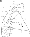
- FIG. 1 is schematically illustrated an end face 14 of a flange 12 of a housing component 10, not shown.
- the end face 14 is formed circumferentially and once circumscribes the flange center point 15.
- the end face 14, so the flange 12 is annular and serves to produce a frictionally engaged and sealed flange 35 with another flange.
- On the end face 14, a plurality of microstructures 40 are formed on a first region 20.
- the microstructures 40 are curved and are arranged concentrically with one another.
- the microstructures 40 in the first region 20 are positioned grouped around a first local center 22 and are arranged concentrically to the first local center 22.
- the first local center 22 is in FIG. 1 on or over the end face 14 of the flange 12.
- the microstructures 40 are seen against a circumferential processing direction 18 of the end face 14, convex. Overall, the microstructures 40 form a sickle share.
- the first local center 22 has a first radial distance 24 from the center of the flange 15. Due to the substantially concentric arrangement of the microstructures 40 about the first local center 22, the first radial spacing 24 is characteristic of the shape and orientation of the microstructures 40.
- a plurality of microstructures 40 are formed in a second region 30, which are also arranged concentrically to each other. Contrary to the circumferential processing direction 18 of the end face 14, the microstructures 40 are convex in the second region 30.
- the microstructures 40 in the second region 30 are arranged concentrically around a second local center 32.
- the second local center 32 lies above or on the end face 14 and has a second radial spacing 34 relative to the flange center 15.
- the first radial distance 24 and the second radial distance 34 are different in magnitude.
- the microstructures 40 in the first and second regions 20, 30 have a different orientation relative to an outer edge 16 and an inner edge 17 of the flange 12.
- a processing path 23 which connects the local center 22, 32.
- the processing path 23 is used in a manufacturing method 100, such as in FIG. 5 shown, in a fourth step 140 traveled by a milling cutter 55, not shown.
- the movement along the machining path 23 includes a circumferential machining direction 18 and a radial machining direction 19.
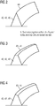
- FIG. 2 shows a microstructure 40 having a triangular cross-section 45, wherein a tip of the triangle forms a cutting line 44.
- the microstructure 40 having the triangular cross-section 45 has a knife shape 42.
- the cutting line 44 when in contact with another surface, presents a line contact with an increased Hertzian stress. This ensures a high degree of tightness.
- the microstructure 40 is curved, so that the cutting line 44 has a curve or a sickle shape.
- FIG. 3 shows a microstructure 40 having a knife shape 42 with a trapezoidal cross-section 47. Due to the size dimensions, an upper side 43 of a microstructure 40 can also be considered as a cutting line 44. The upper side 43 is designed to form a surface contact with a counterpart, not shown. The Hertzian pressure in a surface contact is weaker than in a line contact. As a result, there is a reduced risk that break out of the microstructure 40 at a load and subsequent discharge particles, which can lead to a Reibschwingkorrosion
- FIG. 4 a microstructure 40 with a trapezoidal cross-section 49, whereby a knife shape 42 is realized.
- the trapezoidal cross-section 49 has an inclined top 43.
- a border of the upper side 43 forms a cutting line 44.
- the trapezoidal cross-section 49 represents a transitional shape between the triangular cross section 45 and the trapezoidal cross section 47.
- microstructures 40 which, as in FIG. 1 and 3 are shown, distributed flat, all three cross-sectional shapes 45, 47, 49 are present.
- microstructures 40 having a triangular cross-section 45 are also transformed into microstructures 40 having a trapezoidal or trapezoidal cross-section 47, 49.
- a flange 12 is shown with its end face 14 according to a second embodiment of the housing component 10 according to the invention.
- the end face 14 extends around a flange center 15 and has an outer edge 16 and an inner edge 17.
- a torque arm 25 is formed at the outer edge 16 .
- the torque support 25 is substantially lug-shaped and has a recess 27 for receiving a fastening means, for example a retaining pin 29.
- the housing component 10 is mounted at least on the torque arm 25 so introduced via the recess 27 bearing reaction forces 50 in the housing component 10 become.
- the bearing reaction forces 50 include a radial force 52 and a tangential force 54.
- the housing component 10 is further subject to a circumferential dynamic load 60 by a built-in transmission component.
- the dynamic load 60 includes dynamic radial force 62 and dynamic tangential force 64. Their circulation in operation is indicated by arrow 65. From an interaction of the bearing reaction forces 50 and the dynamic load 60 results in the end face 14 of the flange 12 is a time-varying distribution of mechanical stresses.
- a transition 28 to the torque arm 25 is a first region 20 in which a plurality of microstructures 40 is arranged.
- the transition 28 and the first region 20 overlap at least partially.
- the microstructures 40 in the first region 20 essentially have a sickle shape and are arranged concentrically around a first local center 22.
- the local center point 22 lies radially outside the end face 14 and, by its positioning, determines the orientation of the associated microstructures 40.
- the first region 20 also has maximum mechanical stresses 41, which are designed as shear stresses 46.
- the orientation of the shear stresses 46 is represented by opposing arrow pairs.
- Cutting lines 44 of the microstructures 40 are aligned so that they are substantially transverse to the shear stresses 46.
- the present coefficient of friction is increased in a direction-dependent manner in the first region 20, and thus generates increased static friction in the first region 20.
- a sliding of the first housing component 10 in a flange 35 is thus prevented.
- the shear stresses 46 and the location of their maximum represent the mechanical load in the first area the most significant physical variable in terms of static friction or tendency to slip.
- the present shear stress 46 is for the end face 14 of the flange 12 in a simple manner with a design program, ie a CAD or FEM program, can be determined.
- microstructures 40 are arranged, which are aligned such that their cutting lines 44 are substantially transverse to a comparison voltage 41, which is caused by the mechanical stresses 41 present there.
- the comparison voltage 48 can be determined based on the data of a design program, for example a FEM program, via a selectable expression of the shear stress hypothesis, the shape change hypothesis, or another comparison stress theory.
- the comparison voltage 48 is selected in the second region 30 such that the comparison voltage 48 is the most meaningful for the mechanical stress present in the second region 30 for the present static friction or tendency to slip.
- the alignment of the cutting lines 44 of the microstructures 40 in the second region 30 is determined by the positioning of a second local center 32, which in FIG FIG. 3 radially outside the end face 14 is located. A radial distance 34 of the second local center point 32 differs from the radial distance 24 of the first local center point 22.
- FIG. 6 A fragmentary one embodiment of a housing 70 is shown in FIG FIG. 6 shown to be frictionally coupled with each other in the housing components 10 via a flange 35.
- the housing components 10 are pressed against each other at a mounting on a holding force 36 at their flanges 12.
- the holding force 36 is exercised by means not shown fastening means 37 which are formed as screws.
- microstructures 40 are arranged, which have a knife shape 42.
- the cutting lines 44 of the knife shape 42 are aligned such that the cutting lines 44 of the microstructures 40 of the two housing components 10 are aligned parallel to each other.
- the cutting lines 44 each form a positive connection at the microstructures 40.
- a reinforcing region 51 is formed.
- FIG. 7 schematically a sequence of an embodiment of the manufacturing method 100 according to the invention for a housing component 10 is shown.
- the housing component 10 is initially present as a blank, which has a flange 12 with an end face 14 which is to be machined by machining.
- the housing component 10 is provided with the flange 12 with the end face 14 and in a non-illustrated corresponding processing machine 58, for example, a milling machine, clamped.
- a milling cutter 55 is positioned at a first local center 22. In this case, a milling cutter axis 56 around which the milling cutter 55 rotates during machining is substantially perpendicular to the end face 14.
- a third step 130 follows, in which an exciting machining of the face 14 takes place, in which microstructures 40 on the face 14 in FIG a first area 20 are generated.
- the first region 20 is the immediate vicinity of the local center point 22.
- the milling cutter 55 is moved from the first local center 22 to a second local center 32.
- the milling cutter 55 remains in contact with the end surface 14 so that the machining of the end face 14, which is recorded in the third step 130, is continued.
- essentially sickle-shaped rotational depths are produced on the end face 14, which serve as microstructures 40 for locally increasing a coefficient of friction.
- Turning depths form microstructures that essentially identify a knife shape 42, and thus are suitable for the direction-dependent increase of a local coefficient of friction.
- the cutter When moving from the first to the second local center 22, 32, the cutter follows a predetermined processing path 23.
- the movement of the cutter 55 on the processing path 23 comprises a circumferential processing direction 18 and a radial processing direction 19.
- the alignment of the microstructures 40 produced is adjustable.
- a final state 200 in which a housing component 10 is present, on its end face 14 is occupied with microstructures 40, which essentially have a knife shape 42 and are arranged in a sickle-shaped concentric about local centers 22, 32.
- FIG. 6 An embodiment of a wind turbine according to the invention 80, which has a wind side arranged rotor 82.
- the rotor 82 is torque-transmitting coupled to a transmission 85 which is designed as a planetary gear.
- the transmission 85 in turn is connected to transmit torque to a generator 86 which is designed to generate electrical energy.
- the transmission 85 and the generator are accommodated in a nacelle 84 and belong to a drive train 88 of the wind energy plant 80.
- the transmission 85 has a housing 70 which comprises at least one housing component 10.
- the housing component 10 is formed in accordance with an embodiment of the present invention.
Landscapes
- Engineering & Computer Science (AREA)
- Mechanical Engineering (AREA)
- General Engineering & Computer Science (AREA)
- Optics & Photonics (AREA)
- Physics & Mathematics (AREA)
- Plasma & Fusion (AREA)
- Chemical & Material Sciences (AREA)
- Combustion & Propulsion (AREA)
- Sustainable Energy (AREA)
- Sustainable Development (AREA)
- Life Sciences & Earth Sciences (AREA)
- General Details Of Gearings (AREA)
- Power Steering Mechanism (AREA)
- Milling Processes (AREA)
Abstract
Description
- Die Erfindung betrifft eine Gehäusekomponente mit einem mikrostrukturbesetzten Flansch und ein Verfahren zu dessen Herstellung. Die Erfindung betrifft auch ein Gehäuse mit einer solchen Gehäusekomponente und ein Planetengetriebe.
- Aus
US 2005/0075211 A1 ist ein Planetengetriebe bekannt, das einen Planetenradträger mit einer Mehrzahl an Planetenrädern umfasst. Die Planetenräder sind drehbar auf dem Planetenradträger aufgenommen und stehen im Eingriff mit einem Hohlrad. Die Planetenräder sind auf Planetenradachsen gelagert, die einen Schaft aufweisen, der in einer Wange des Planetenradträgers aufgenommen ist. Der Schaft ist im Wesentlichen zylindrisch ausgebildet. Der Durchmesser des Schafts ist unter Berücksichtigung der vorliegenden Materialeigenschaften und Mikrostrukturen derart ausgewählt, dass eine maximal zulässige von-Mises-Vergleichsspannung nicht überschritten wird. - Der Forschungsreport 2014 vom 11.12.2014 zum Projekt "Gestaltung und Ermittlung charakteristischer Kennwerte von reibschlussoptimierten Oberflächen", kurz GECKO, offenbart in Kapitel 4.4 eine Simulation von Mikrostrukturen, die im Wesentlichen messerförmig ausgebildet sind. Die messerförmigen Mikrostrukturen sind dabei in unterschiedlichen Simulationsdurchgängen in einer gegengerichteten und einer gekreuzten Riefenanordnung ausgerichtet. Ferner ist in Kapitel 5 ein Gestaltungsleitfaden für unbeschichtete reibschlüssige Oberflächen offenbart.
- Das Dokument
WO 2006/128523 A1 offenbart eine Anlaufscheibe eines Ausrücklagers einer Schalttrennkupplung mit einer kupplungsfernen Fläche. Die Anlaufscheibe ist aus Kunststoff hergestellt und weist auf ihrer kupplungsfernen Fläche Mikrostrukturen auf, die durch Anspritzen oder spanloses Einformen hergestellt sind. Die Mikrostrukturen sind rippenförmig ausgebildet und radial oder über die kupplungsferne Fläche hinweg kreuzförmig ausgerichtet. - Es besteht die Zielsetzung, höhere Drehmomente und Leistungen durch baulich kompaktere Getriebe zu führen und so die vorliegende Drehzahl anzupassen. Beispielsweise besteht im Bereich von Getrieben für Windenergieanlagen eine solche technische Zielsetzung. Eine derartige bauraumbezogene Leistungssteigerung stellt erhöhte Anforderungen an sämtliche Komponenten des Getriebes. Insbesondere besteht Bedarf an Gehäusekomponenten, die trotz steigender mechanischer Beanspruchung an ihren Flanschflächen zueinander fest sitzen, also keine oder nur eine reduzierte Relativbewegung zueinander aufweisen. Insgesamt besteht Bedarf an einer verbesserten Gehäusekomponente, die die skizzierten Anforderungen erfüllt und gleichzeitig einfach, schnell und wirtschaftlich herstellbar ist.
- Die Aufgabenstellung wird durch die erfindungsgemäße Gehäusekomponente gelöst. Die Gehäusekomponente weist einen Flansch auf, der dazu ausgebildet ist, mit einer weiteren Gehäusekomponente eine reibschlüssige Flanschverbindung herzustellen. Der Flansch weist eine Stirnfläche auf, die im Wesentlichen als plane umlaufende Fläche ausgebildet ist. Der Flansch weist eine Mehrzahl an Ausnehmungen auf, die zur Aufnahme von lösbaren Befestigungselementen ausgebildet sind, wie beispielsweise Schrauben oder Bolzen. In einem ersten und einem zweiten Bereich auf der Stirnfläche des Flansches ist jeweils eine Mehrzahl an Mikrostrukturen ausgebildet. An Stellen, an denen Mikrostrukturen im ersten und/oder zweiten Bereich ausgebildet sind, liegt eine Erhöhung des lokalen Reibwerts vor. Der lokale Reibwert ist der Reibwert, der zusammen mit einer in der Flanschverbindung über die Befestigungselemente ausgeübten Haltekraft die Haftreibung definiert, die in der Ebene der Stirnfläche vorliegt. Die Mikrostrukturen weisen im Wesentlichen eine Messerform mit einer Schneidlinie auf. Durch diese Form rufen die Mikrostrukturen eine richtungsabhängige Erhöhung des lokalen Reibwerts hervor.
- Die Schneidlinien der Mikrostrukturen sind erfindungsgemäß im ersten Bereich konzentrisch um einen ersten Lokalmittelpunkt angeordnet und ausgerichtet. Der erste Lokalmittelpunkt beschreibt einen Punkt, der auf der Stirnfläche des Flansches oder radial neben der Stirnfläche des Flansches liegt und der ein geometrisches Zentrum für eine Mehrzahl an Schneidlinien bildet. Gleichermaßen sind die Schneidlinien der Mikrostrukturen im zweiten Bereich konzentrisch um einen zweiten Lokalmittelpunkt angeordnet und ausgerichtet, der auch auf der Stirnfläche des Flansches liegt oder radial neben der Stirnfläche des Flansches. Bezogen auf einen Flanschmittelpunkt weisen der erste und der zweite Lokalmittelpunkt unterschiedliche Radialabstände auf. Infolgedessen weisen die Schneidlinien der Mikrostrukturen im ersten und zweiten Bereich bezogen auf eine Umrandung der Stirnfläche unterschiedliche Ausrichtungen auf.
- Aufgrund der richtungsabhängigen Wirkung der Mikrostrukturen bei der Erhöhung des lokalen Reibwerts liegen so im ersten und zweiten Bereich unterschiedliche stark erhöhte lokale Reibwerte vor. Durch geeignetes Positionieren des ersten und zweiten Lokalmittelpunkts ist somit in wählbaren Abschnitten einer Flanschverbindung eine erhöhte Haftreibung erzielbar. Die erhöhte Haftreibung erlaubt es, in mechanisch hoch beanspruchten Abschnitten eine Relativbewegung der Gehäusekomponente in der Flanschverbindung zu verhindern. Gleichzeitig wird durch die so verbesserte Flanschverbindung auch eine verbesserte Dichtung am Flansch gewährleistet. Dies erlaubt die Herstellung einer belastbareren Flanschverbindung.
- Bei der beanspruchten Gehäusekomponente können die Mikrostrukturen im ersten und/oder zweiten Bereich zumindest teilweise als Drehriefen ausgebildet sein, die von einem Fräser bei der Zerspanung einer metallischen Oberfläche hinterlassen werden. Drehriefen weisen senkrecht zu einer Stirnfläche eines Flansches Abmessungen von bis zu 100 µm auf und stellen damit Mikrostrukturen dar. Drehriefen bilden auch eine im Wesentlichen messerförmige Kontur und stellen eine einfache Art und Weise dar, die Mikrostrukturen herzustellen. Darüber hinaus bilden Drehriefen im Wesentlichen konzentrische Kreislinien. Die Stirnfläche des Flansches an der beanspruchten Gehäusekomponente ist folglich schnell und wirtschaftlich herstellbar. Alternativ oder ergänzend können die Mikrostrukturen im ersten und/oder zweiten Bereich durch eine Laserbearbeitung der Stirnfläche des Flansches hergestellt sein. Mittels Laserbearbeitung hergestellte Mikrostrukturen sind frei von geometrischen Zwängen herstellbar. Dadurch können Mikrostrukturen an Positionen und in Ausrichtungen herstellt werden, die für einen Fräser, der Drehriefen erzeugt, nicht erreichbar sind.
- Bevorzugt ist die Messerform der Mikrostrukturen derart ausgebildet, dass die Mikrostrukturen einen im Wesentlichen dreieckigen Querschnitt aufweisen. Ein dreieckiger Querschnitt stellt die einfachste Form dar, die eine Mikrostruktur mit einer definierten Schneidlinien liefert. Die Schneidlinie stellt einen linienförmigen Kontakt dar, der eine erhöhte Hertz'sche Pressung, und damit eine erhöhte Haftreibung hervorruft. Alternativ oder ergänzend können die Mikrostrukturen auch einen trapezförmigen oder trapezoidförmigen Querschnitt aufweisen. Bei einer Stirnfläche, die aus einem härteren Material hergestellt ist als ein Gegenkörper für die Flanschverbindung, besteht bei einem trapezförmigen oder trapezoidförmigen Querschnitt ein reduziertes Risiko, dass Materialpartikel aus der Stirnfläche abbrechen und so eine Reibschwingkorrosion hervorrufen. Dabei bieten trapezförmige und trapezoidförmige auf ihrer Oberseite einen schmalen Flächenkontakt, der ähnlich hohe Haftreibung bietet wie ein dreieckiger Querschnitt. Dreieckige, trapezförmige und trapezoidförmige Querschnitte der Mikrostrukuren bieten eine definierte richtungsabhängige Erhöhung des lokalen Reibwerts.
- Des Weiteren können in der beanspruchten Gehäusekomponente die Schneidlinien der Mikrostrukturen im ersten und/oder zweiten Bereich im Wesentlichen quer zu einer Ausrichtung einer mechanischen Spannung an der Stirnfläche des Flansches ausgerichtet sein. Die Ausrichtung kann dabei auf eine Hauptspannungsachse eines überlagerten Spannungszustands an der entsprechenden Stelle im ersten und/oder zweiten Bereich bezogen sein. Alternativ kann die Ausrichtung der Schneidlinien der Mikrostrukturen auch auf eine entsprechend ausgerichtete und gewählte Vergleichsspannung, beispielsweise einer von-Mises-Spannung, also einer Spannung gemäß der Gestaltänderungshypothese, einer Tresca, Coulomb-, Saint-Venant-, oder Guest-Spannung bezogen sein, die auf der Schubspannungshypothese beruhen. Ebenso kann die Ausrichtung der Schneidlinien der Mikrostrukturen auch auf eine Rankine-Spannung bezogen sein, die auf der Hauptnormalspannungshypothese basiert. In analoger Form sind auch andere Vergleichsspannungen gemäß den bekannten Hypothesen möglich. Derartige Spannungen und/oder Vergleichsspannungen sind in einfacher Weise durch heutige Konstruktionsprogramme, insbesondere CAD- und FEM-Programme, schnell und hochauflösend berechenbar. Eine entsprechende geeignete Ausrichtung der Mikrostrukturen, bei der eine maximale Erhöhung des lokalen Reibwerts erzielt wird, kann damit im ersten und/oder zweiten Bereich gezielt hergestellt werden. Die beanspruchte Gehäusekomponente ist somit effektiv an unterschiedliche Anforderungen konstruktiv anpassbar.
- Vorzugsweise ist die mechanische Spannung, zu der die Schneidlinien der Mikrostrukturen im Wesentlichen quer ausgerichtet sind, die vorliegende Schubspannung. Dabei handelt es sich um die Schubspannungen, die sind im angepressten Zustand bei einer Flanschverbindung zwischen den beteiligten Flanschen im bestimmungsgemäßen Betrieb, beispielsweise bei einem Getriebe, insbesondere einem Planetengetriebe, einstellt. Die Schneidlinien der Mikrostrukturen schneiden sich damit zumindest abschnittsweise mit der Richtung, die die Schubspannung im Bereich dieser Mikrostrukturen, beispielsweise in einem Zwischenraum zwischen zwei Mikrostrukturen, einnimmt. Schubspannungen ergeben sich über den Mohr'schen Spannungskreis algebraisch aus zwei vorliegenden Spannungen.
- Schubspannungen sind durch heutige Konstruktionsprogramme, also CAD- und FEM-Programme, sehr einfach und schnell berechenbar. Der Erfindung liegt unter anderem die Erkenntnis zugrunde, dass im Bereich erhöhter Schubspannungen in einer Flanschverbindung die stärkste Neigung besteht, von einem Haftreibungszustand in einen Gleitreibungszustand überzugehen. Folglich sind die Bereiche, in denen ein Verlust der Haftreibung, und damit des festen Sitzes der Gehäusekomponente, im bestimmungsgemäßen Betrieb am stärksten drohen, durch Heranziehung der vorliegenden Schubspannung als Kriterium besonders schnell identifizierbar. Deshalb wird durch die Mikrostrukturen nur mittels einer Bearbeitung eines begrenzten Bereichs auf der Stirnfläche des Flansches der gesamte Flansch stabiler gestaltet.
- In einer weiteren Ausführungsform der beanspruchten Gehäusekomponente sind die Mikrostrukturen im ersten und/oder zweiten Bereich angeordnet, wobei im ersten und/oder zweiten Bereich eine maximale mechanische Spannung vorliegt, die höher ist als ein wählbarer, also einstellbarer, Schwellenwert. Der Schwellenwert ist durch eine Benutzereingabe oder durch einen Algorithmus eines Konstruktionsprogramms einstellbar. Durch den wählbaren Schwellenwert sind gezielt Bereiche als erster und/oder zweiter Bereich festlegbar, in denen Mikrostrukturen auszubilden sind. Dies gewährleistet, jeglichen Bereich, in dem bei bestimmungsgemäßer mechanischer Beanspruchung des Flansches mittels Mikrostrukturen gegen eine Gleitbewegung in der Flanschverbindung stützbar, also verstärkbar. Durch geeignete Wahl des Schwellenwerts ist es möglich, gezielt die Bereiche zu identifizieren, in denen eine Mikrostruktur eine Erhöhung der vorliegenden Haftreibung hervorruft. Der Aufwand zur Herstellung der Mikrostrukturen wird somit auf ein Minimum reduziert, so dass die beanspruchte Gehäusekomponente schnell und wirtschaftlich herstellbar ist.
- In einer bevorzugten Ausführungsform der beanspruchten Gehäusekomponente liegen der erste und/oder zweite Bereich an einem Übergang zu einer Drehmomentstütze. Die Drehmomentstütze ist dabei vorzugsweise einstückig an die Gehäusekomponente angeformt, beispielsweise integral durch Gießen hergestellt. An der Drehmomentstütze ist zumindest teilweise die Gewichtskraft der Gehäusekomponente und beispielsweise des darin befindlichen Getriebes aufgenommen. Ferner wird bei einem Planetengetriebe durch umlaufende Planetenräder eine Verformungslast auf dessen Hohlrad, und darüber auf die zugehörige Gehäusekomponente übertragen. Zusätzlich tritt am Übergang zu einer Drehmomentstütze in der Gehäusekomponente eine Zu- bzw. Abnahme an Steifigkeit auf. Die Kombination aus dieser Steifigkeitsänderung, der periodisch umlaufenden Verformungslast und der statischen Gewichtskraft führt zu erhöhten mechanischen Spannungen, insbesondere Schubspannungen, am Übergang zu einer Drehmomentstütze. Infolgedessen werden die oben skizzierten Vorteile der beanspruchten Gehäusekomponente am Übergang zu einer Drehmomentstütze in besonderem Umfang erzielt.
- Die skizzierte Aufgabenstellung wird auch durch das erfindungsgemäße Verfahren zur Herstellung einer Gehäusekomponente gelöst. Die Gehäusekomponente verfügt über einen Flansch mit einer Stirnfläche. Der Flansch ist dazu ausgebildet, mit einem Flansch einer weiteren Gehäusekomponente eine reibschlüssige Verbindung, also eine Flanschverbindung, herzustellen. Das erfindungsgemäße Verfahren umfasst eine Mehrzahl an Schritten. In einem ersten Verfahrensschritt wird eine Gehäusekomponente bereitgestellt, wobei die Stirnfläche eines Flansches spanend zu bearbeiten ist. In einem weiteren Schritt wird ein Fräser relativ zur Gehäusekomponente positioniert. Eine Fräserachse, um die sich der Fräser im Betrieb dreht, ist dabei im Wesentlichen senkrecht zur Stirnfläche ausgerichtet. Der Fräser wird derart positioniert, dass die Fräserachse durch einen ersten Lokalmittelpunkt verläuft. In einem weiteren Schritt erfolgt eine spanende Bearbeitung der Stirnfläche des Flansches mit dem Fräser. Bei der spanenden Bearbeitung durch den Fräser werden auf der Stirnfläche des Fräsers Mikrostrukturen in Form von Drehriefen erzeugt. In einem weiteren Schritt erfolgt ein Bewegen des Fräsers vom ersten Lokalmittelpunkt zu einem zweiten Lokalmittelpunkt. Während des Bewegens von ersten zum zweiten Lokalmittelpunkt erfolgt weiterhin eine spanende Bearbeitung der Stirnfläche des Flansches. Bezogen auf eine Bewegungsrichtung des Fräsers werden die Mikrostrukturen an einem hinteren Abschnitt des Fräsers erzeugt. Erfindungsgemäß umfasst die Bewegung des Fräsers eine Bewegung in einer Umfangsbearbeitungsrichtung und eine Bewegung in einer Radialbearbeitungsrichtung. Die Umfangsbearbeitungsrichtung folgt dabei im Wesentlichen der Stirnfläche. Die Radialbearbeitungsrichtung ist auf einen Flanschmittelpunkt bezogen, um den herum die Stirnfläche verläuft.
- Das erfindungsgemäße Verfahren erlaubt es, in einfacher Weise Mikrostrukturen auf einer Stirnfläche eines Flansches herzustellen. Insbesondere erfolgt die Herstellung lediglich mit Werkzeug, das beispielsweise in der Getriebefertigung ohnehin zum Einsatz kommt. Die Verwendung von Spezialwerkzeug ist somit entbehrlich. Durch die entsprechende Ansteuerung des Fräsers ist es einfach möglich, die Position und die Ausrichtung der Mikrostrukturen gezielt einzustellen. Dies erlaubt es insgesamt, eine mechanisch stärker beanspruchbare Gehäusekomponente herzustellen.
- In einer bevorzugten Ausführungsform des beanspruchten Verfahrens weist der Fräser einen Fräserdurchmesser auf, der eine Flanschbreite, also eine radiale Abmessung der Stirnfläche des Flansches, übersteigt. Dadurch sind über die gesamte Flanschbreite Mikrostrukturen herstellbar, die Stirnfläche bogenförmig bis annähernd geradlinig überqueren. Mit einem derartigen Fräser sind auf einer Fläche annähernd konstante Mikrostrukturen herstellbar, wodurch in einem Segment der Stirnfläche durchgehend eine gleichartige richtungsabhängige Erhöhung des lokalen Reibwerts erzielbar ist. Insbesondere ist eine schnelle spanende Bearbeitung der Stirnfläche möglich.
- Des Weiteren kann im beanspruchten Herstellungsverfahren der erste und/oder zweite Lokalmittelpunkt radial außerhalb der Stirnfläche des Flansches liegen. Dadurch ist es möglich, beispielsweise bei Verwendung von Fräsern mit erhöhtem Durchmesser, die Krümmung der Schneidlinien der herzustellenden Mikrostrukturen auf der Stirnfläche exakt einzustellen. Insbesondere sind am Rand der Stirnfläche reduzierte Krümmungen der Schneidlinien der Mikrostrukturen erzielbar. Hierdurch ist mit dem beanspruchten Verfahren eine erhöhte konstruktive Freiheit bei der Gestaltung der Mikrostrukturen erzielbar, und somit die gewünschte lokale Erhöhung des Reibwerts exakter einstellbar.
- Gleichermaßen wird die beschriebene Aufgabenstellung durch das erfindungsgemäße Gehäuse gelöst. Das Gehäuse dient der Aufnahme einer mechanischen oder elektromechanischen Anwendung, beispielsweise für ein Getriebe oder einen Elektromotor. Im Gehäuse sind Bauteile der mechanischen oder elektromechanischen Anwendung angeordnet, die sich zumindest teilweise im bestimmungsgemäßen Betrieb am Gehäuse abstützen. Das Gehäuse umfasst eine erste und eine zweite Gehäusekomponente, die jeweils einen Flansch mit einer Stirnfläche aufweisen. Die erste und zweite Gehäusekomponente sind über Befestigungsmittel, beispielsweise Schrauben oder Bolzen, lösbar miteinander reibschlüssig verbunden und bilden eine Flanschverbindung. Erfindungsgemäß sind die erste und/oder die zweite Gehäusekomponente gemäß mindestens einer der oben beschriebenen Ausführungsformen ausgebildet. Ein derartiges Gehäuse bietet in der Flanschverbindung eine erhöhte Haftreibung, so dass das Gehäuse dazu geeignet ist, bei gleichbleibender Baugröße erhöhte Stützkräfte von Bauteilen der mechanischen oder elektromechanischen Anwendung und/oder Lagerreaktionskräfte aufzunehmen. Gleichzeitig wird in der Flanschverbindung die Dichtwirkung gesteigert. Ferner ist die mindestens eine erfindungsgemäß ausgebildete Gehäusekomponente dabei einfach und wirtschaftlich herstellbar.
- Vorzugsweise sind im beanspruchten Gehäuse die Mikrostrukturen derart ausgebildet, dass Schneidlinien der Mikrostrukturen auf den Stirnflächen der Flansche der ersten und zweiten Gehäusekomponente zueinander im Wesentlichen parallel angeordnet sind. Der Bereich, in dem die Schneidlinien der Mikrostrukturen parallel zueinander ausgebildet sind, bildet somit einen Verstärkungsbereich. Parallel angeordnete Schneidlinien von Mikrostrukturen erlauben einen wechselseitigen Formschluss, durch den eine weitere richtungsabhängige Erhöhung des lokalen Reibwerts erzielt wird. Ein solcher Verstärkungsbereich bietet ein besonders hohes Maß an Haftreibung an Stellen, wo beispielsweise eine erhöhte mechanische Spannung, insbesondere Schubspannung, oder Vergleichsspannung vorliegt. Insgesamt werden die technischen Vorteile der beanspruchten Gehäusekomponente so im Zusammenspiel mit einer weiteren gleich oder ähnlich ausgebildeten Gehäusekomponente in besonders hohem Umfang erzielt.
- Ferner kann im beanspruchten Gehäuse die erste Gehäusekomponente aus einem härten Werkstoff hergestellt sein als die zweite Gehäusekomponente. Die Mikrostrukturen auf der Stirnfläche des Flansches der ersten Gehäusekomponente weisen dabei eine höhere Rauigkeit auf als die Mikrostrukturen auf der Stirnfläche des Flansches der zweiten Gehäusekomponente. Eine höhere Rauigkeit wird hierbei durch eine höhere Abmessung der Mikrostrukturen senkrecht zur entsprechenden Stirnfläche hervorgerufen. Eine solche Zusammenstellung einer ersten Gehäusekomponente mit härteren und raueren Mikrostrukturen als auf der Stirnfläche der zweiten Gehäusekomponente stellt eine besonders vorteilhafte Zusammenstellung dar, die die angestrebten Vorteile der Erfindung in besonderem Umfang verwirklichen.
- Die beschriebene Aufgabe wird auch durch das erfindungsgemäße Planetengetriebe gelöst. Das Planetengetriebe umfasst ein Gehäuse, zu dem zumindest eine erste Gehäusekomponente gehört. In der ersten Gehäusekomponente ist ein Hohlrad aufgenommen, in dem im bestimmungsgemäßen Betrieb mindestens ein Planetenrad läuft. Dazu ist das Planetenrad drehbar in einem Planetenradträger gelagert. Durch das Planetenrad werden im Hohlrad Reaktionskräfte hervorgerufen, die mit dem Planetenrad umlaufen. Die Reaktionskräfte werden wiederum von Hohlrad an die erste Gehäusekomponente weitergeleitet. Erfindungsgemäß ist die erste Gehäusekomponente gemäß einer der oben beschriebenen Ausführungsformen ausgebildet. Ein derartiges Planetengetriebe bietet die Möglichkeit, bei erhöhten Drehmomenten die vorliegende Drehzahl anzupassen. In einem Planetengetriebe werden die technischen Vorteile der erfindungsgemäßen Gehäusekomponente erzielt.
- Gleichermaßen wird die skizzierte Aufgabenstellung durch eine erfindungsgemäße Windenergieanlage erzielt. Die Windenergieanlage umfasst einen Rotor, der mit einer Gondel verbunden ist. Der Rotor ist auch über ein Getriebe mit einem Generator verbunden. Die vom Rotor gelieferte Wellenleistung wird durch das Getriebe erhöht und dem Generator so eine erhöhte Drehzahl für die Energiegewinnung zur Verfügung gestellt. Das Getriebe ist dabei als Planetengetriebe gemäß einer oben skizzierten Ausführungsform ausgebildet. Das Planetengetriebe bietet bei gleicher Baugröße eine erhöhte Leistungsdichte, also ein höheres Verhältnis von umgesetzter Wellenleistung zu Bauvolumen. Hierdurch ist ein kompakterer Aufbau der Komponenten in der Gondel möglich.
- Die Erfindung wird im Folgenden anhand von Figuren einzelner Ausführungsformen beschrieben. Die Merkmale der Figuren sind dabei ohne weiteres untereinander kombinierbar. Es zeigen im Einzelnen:
- FIG 1
- schematisch eine Stirnfläche eines Flansches an einer Gehäusekomponente gemäß einer ersten Ausführungsform der Erfindung;
- FIG 2-4
- eine Mehrzahl aus Ausführungsformen einer Mikrostruktur;
- FIG 5
- schematisch eine Stirnfläche eines Flansches an einer Gehäusekomponente gemäß einer zweiten Ausführungsform der Erfindung;
- FIG 6
- einen Ausschnitt einer Ausführungsform eines erfindungsgemäßen Gehäuses;
- FIG 7
- schematisch ein Ablaufdiagramm einer Ausführungsform des erfindungsgemäßen Herstellungsverfahrens;
- FIG 8
- eine Ausführungsform einer erfindungsgemäßen Windenergieanlage.
- In
FIG 1 ist schematisch eine Stirnfläche 14 eines Flansches 12 einer nicht näher dargestellten Gehäusekomponente 10 abgebildet. Die Stirnfläche 14 ist umlaufend ausgebildet und umrundet einmal den Flanschmittelpunkt 15. Die Stirnfläche 14, also der Flansch 12 ist ringförmig ausgebildet und dient dazu, mit einem weiteren Flansch eine reibschlüssige und dichte Flanschverbindung 35 herzustellen. Auf der Stirnfläche 14 ist ein einem ersten Bereich 20 eine Mehrzahl an Mikrostrukturen 40 ausgebildet. Die Mikrostrukturen 40 sind gekrümmt ausgebildet und sind zueinander konzentrisch angeordnet. Die Mikrostrukturen 40 im ersten Bereich 20 sind um einen ersten Lokalmittelpunkt 22 gruppiert positioniert und sind zum ersten Lokalmittelpunkt 22 konzentrisch angeordnet. Der erste Lokalmittelpunkt 22 liegt inFIG 1 auf oder über der Stirnfläche 14 des Flansches 12. Die Mikrostrukturen 40 sind entgegen einer Umfangsbearbeitungsrichtung 18 der Stirnfläche 14 gesehen, konvex ausgebildet. Insgesamt bilden die Mikrostrukturen 40 eine Sichelschar. Der erste Lokalmittelpunkt 22 weist von Flanschmittelpunkt 15 einen ersten Radialabstand 24 auf. Durch die im Wesentlichen konzentrische Anordnung der Mikrostrukturen 40 um den ersten Lokalmittelpunkt 22 ist der erste Radialabstand 24 charakteristisch für die Form und Ausrichtung der Mikrostrukturen 40. - Auf der Stirnfläche 14 ist in einem zweiten Bereich 30 auch eine Mehrzahl an Mikrostrukturen 40 ausgebildet, die auch zueinander konzentrisch angeordnet sind. Entgegen der Umfangsbearbeitungsrichtung 18 der Stirnfläche 14 sind die Mikrostrukturen 40 im zweiten Bereich 30 konvex ausgebildet. Die Mikrostrukturen 40 im zweiten Bereich 30 sind konzentrisch um einen zweiten Lokalmittelpunk 32 angeordnet. Der zweite Lokalmittelpunkt 32 liegt über oder auf der Stirnfläche 14 und weist zum Flanschmittelpunkt 15 einen zweiten Radialabstand 34 auf. Der erste Radialabstand 24 und der zweite Radialabstand 34 sind dem Betrag nach unterschiedlich groß. Dadurch liegt für die Mikrostrukturen 40 im ersten und zweiten Bereich 20, 30 eine unterschiedliche Ausrichtung bezogen auf einen Außenrand 16 und einen Innenrand 17 des Flansches 12 vor. Zwischen dem ersten und zweiten Lokalmittelpunkt 22, 32 liegt ein Bearbeitungspfad 23, der die Lokalmittelpunkt 22, 32 verbindet. Entlang des Bearbeitungspfades 23 sind weitere Mikrostrukturen 40 ausgebildet, die eine Sichelform aufweisen und den Bearbeitungspfad 23 im Wesentlichen senkrecht schneiden. Der Bearbeitungspfad 23 wird bei einem Herstellungsverfahren 100, wie beispielsweise in
FIG 5 abgebildet, in einem vierten Schritt 140 von einem nicht näher abgebildeten Fräser 55 abgefahren. Die Bewegung entlang des Bearbeitungspfads 23 umfasst eine Umfangsbearbeitungsrichtung 18 und eine Radialbearbeitungsrichtung 19. - Eine Mehrzahl an Profilen von Mikrostrukturen 40, mit denen die erfindungsgemäße Gehäusekomponente 10 verwirklichbar ist, ist in
FIG 2 bis FIG 4 abgebildet.FIG 2 zeigt eine Mikrostruktur 40, die einen dreieckigen Querschnitt 45 aufweist, wobei eine Spitze des Dreiecks eine Schneidlinie 44 ausbildet. Infolgedessen hat die Mikrostruktur 40 mit dem dreieckigen Querschnitt 45 eine Messerform 42. Die Schneidlinie 44 stellt bei einem Kontakt mit einer anderen Oberfläche einen Linienkontakt dar, an dem eine erhöhte Hertz'sche Pressung vorliegt. Dies gewährleistet ein hohes Maß an Dichtigkeit. Die Mikrostruktur 40 ist gekrümmt ausgebildet, so dass die Schneidlinie 44 eine Kurve bzw. eine Sichelform aufweist. -
FIG 3 zeigt eine Mikrostruktur 40, die eine Messerform 42 mit einem trapezförmigen Querschnitt 47 aufweist. Aufgrund der Größendimensionen kann eine Oberseite 43 einer Mikrostruktur 40 auch als Schneidlinie 44 betrachtet werden. Die Oberseite 43 ist dazu ausgebildet, mit einem nicht näher dargestellten Gegenkörper einen Flächenkontakt auszubilden. Die Hertz'sche Pressung in einem Flächenkontakt ist schwächer als in einem Linienkontakt. Infolgedessen besteht eine verringerte Gefahr, dass aus der Mikrostruktur 40 bei einer Belastung und anschließender Entlastung Partikel herausbrechen, die zu einer Reibschwingkorrosion führen können - Des Weiteren zeigt
FIG 4 eine Mikrostruktur 40 mit einem trapezoidförmigen Querschnitt 49, wodurch auch eine Messerform 42 verwirklicht ist. Der trapezoidförmige Querschnitt 49 weist eine geneigte Oberseite 43 auf. Eine Umrandung der Oberseite 43 bildet hierbei eine Schneidlinie 44. Der trapezoidförmige Querschnitt 49 stellt eine Übergangsform zwischen dem dreieckigen Querschnitt 45 und dem trapezförmigen Querschnitt 47 dar. In Mikrostrukturen 40, die wie inFIG 1 und3 dargestellt, flächig verteilt liegen, liegen alle drei Querschnittsformen 45, 47, 49 vor. Durch plastische Verformung werden auch beispielsweise Mikrostrukturen 40 mit dreieckigem Querschnitt 45 in Mikrostrukturen 40 mit trapezförmigem oder trapezoidförmigem Querschnitt 47, 49 umgewandelt. - In
FIG 5 ist ein Flansch 12 mit seiner Stirnfläche 14 gemäß einer zweiten Ausführungsform der erfindungsgemäßen Gehäusekomponente 10 dargestellt. Die Stirnfläche 14 umläuft einen Flanschmittelpunkt 15 und weist einen Außenrand 16 und einen Innenrand 17 auf. Am Außenrand 16 ist eine Drehmomentstütze 25 ausgebildet. Die Drehmomentstütze 25 ist im Wesentlichen laschenförmig und verfügt über eine Ausnehmung 27 zur Aufnahme eines Befestigungsmittels, beispielsweise eines Haltebolzens 29. Die Gehäusekomponente 10 ist zumindest über die Drehmomentstütze 25 gelagert, so über die Ausnehmung 27 Lagerreaktionskräfte 50 in die Gehäusekomponente 10 eingeleitet werden. Die Lagerreaktionskräfte 50 umfassen eine Radialkraft 52 und eine Tangentialkraft 54. Die Gehäusekomponente 10 ist ferner durch eingebaute Getriebekomponente einer umlaufenden dynamischen Belastung 60 unterworfen. Die dynamische Belastung 60 umfasst dynamische Radialkraft 62 und eine dynamische Tangentialkraft 64. Deren Umlauf im Betrieb ist durch den Pfeil 65 abgebildet. Aus einem Zusammenspiel der Lagerreaktionskräfte 50 und der dynamischen Belastung 60 ergibt sich in der Stirnfläche 14 des Flansches 12 eine zeitlich veränderliche Verteilung von mechanischen Spannungen. - An einem Übergang 28 zur Drehmomentstütze 25 liegt ein erster Bereich 20, in dem eine Mehrzahl an Mikrostrukturen 40 angeordnet ist. Der Übergang 28 und der erste Bereich 20 überlappen sich dabei zumindest teilweise. Die Mikrostrukturen 40 im ersten Bereich 20 weisen im Wesentlichen eine Sichelform auf und sind konzentrisch um einen ersten Lokalmittelpunkt 22 angeordnet. Der Lokalmittelpunkt 22 liegt radial außerhalb der Stirnfläche 14 und bestimmt durch seine Positionierung die Ausrichtung der zugehörigen Mikrostrukturen 40. Im ersten Bereich 20 liegen auch maximale mechanische Spannungen 41 vor, die als Schubspannungen 46 ausgebildet sind. Die Ausrichtung der Schubspannungen 46 ist durch gegenläufige Pfeilpaare dargestellt. Schneidlinien 44 der Mikrostrukturen 40 sind derart ausgerichtet, dass sie im Wesentlichen quer zu den Schubspannungen 46 liegen. Hierdurch wird im ersten Bereich 20 der vorliegende Reibwert richtungsabhängig gesteigert, und so eine erhöhte Haftreibung im ersten Bereich 20 erzeugt. Einem Gleiten der ersten Gehäusekomponente 10 in einer Flanschverbindung 35 wird so vorgebeugt. Die Schubspannungen 46 bzw. der Ort deren Maximums, stellen für die mechanische Beanspruchung im ersten Bereich die aussagekräftigste physikalische Größe in puncto Haftreibung bzw. Gleitneigung dar. Die vorliegende Schubspannung 46 ist für die Stirnfläche 14 des Flansches 12 in einfacher Weise mit einem Konstruktionsprogramm, also einem CAD- oder FEM-Programm, ermittelbar.
- Gleichermaßen sind in einem zweiten Bereich 30 Mikrostrukturen 40 angeordnet, die derart ausgerichtet sind, dass deren Schneidlinien 44 im Wesentlichen quer zu einer Vergleichsspannung 41 liegen, die durch die dort vorliegenden mechanischen Spannungen 41 hervorgerufen wird. Die Vergleichsspannung 48 sind basierend auf den Daten eines Konstruktionsprogramms, beispielsweise eines FEM-Programms, über eine auswählbare Ausprägung der Schubspannungshypothese, der Gestaltänderungshypothese, oder einer weiteren Vergleichsspannungstheorie ermittelbar. Die Vergleichsspannung 48 ist im zweiten Bereich 30 derart gewählt, dass die Vergleichsspannung 48 für die im zweiten Bereich 30 vorliegende mechanische Beanspruchung für die vorliegende Haftreibung bzw. Gleitneigung am aussagekräftigsten ist. Die Ausrichtung der Schneidlinien 44 der Mikrostrukturen 40 im zweiten Bereich 30 ist durch die Positionierung eines zweiten Lokalmittelpunkts 32 bestimmt, der in
FIG 3 radial außerhalb der Stirnfläche 14 liegt. Ein Radialabstand 34 des zweiten Lokalmittelpunkts 32 unterscheidet sind dabei vom Radialabstand 24 des ersten Lokalmittelpunkts 22. - Eine ausschnitthaft eine Ausführungsform eines Gehäuses 70 ist in
FIG 6 dargestellt, in den Gehäusekomponenten 10 über eine Flanschverbindnung 35 reibschlüssig miteinander zu koppeln sind. Die Gehäusekomponenten 10 werden bei einer Montage über eine Haltekraft 36 an ihren Flanschen 12 aneinander gedrückt. Die Haltekraft 36 wird über nicht näher dargestellte Befestigungsmittel 37, die als Schrauben ausgebildet sind, ausgeübt. An den Stirnflächen 14 der Flansche 12 sind Mikrostrukturen 40 angeordnet, die eine Messerform 42 aufweisen. Die Schneidlinien 44 der Messerform 42 sind derart ausgerichtet, dass die Schneidlinien 44 der Mikrostrukturen 40 der beiden Gehäusekomponenten 10 zueinander parallel ausgerichtet sind. Bei einem Ineinandergreifen der Mikrostrukturen 40 bilden die Schneidlinien 44 jeweils an den Mikrostrukturen 40 einen Formschluss aus. Hierdurch wird eine erhebliche Erhöhung des Reibwerts an der entsprechenden Stelle erzielt. Hierdurch wird ein Verstärkungsbereich 51 gebildet. - In
FIG 7 ist schematisch ein Ablauf einer Ausführungsform des erfindungsgemäßen Herstellungsverfahrens 100 für eine Gehäusekomponente 10 dargestellt. Die Gehäusekomponente 10 liegt dabei zunächst als Rohteil vor, das einen Flansch 12 mit einer Stirnfläche 14 aufweist, die durch spanende Bearbeitung zu bearbeiten ist. In einem ersten Schritt 110 wird die Gehäusekomponente 10 mit dem Flansch 12 mit der Stirnfläche 14 bereitgestellt und in eine nicht näher dargestellte entsprechende Bearbeitungsmaschine 58, beispielsweise einer Fräsmaschine, eingespannt. In einem darauffolgenden zweiten Schritt 120 wird ein Fräser 55 an einem ersten Lokalmittelpunkt 22 positioniert. Dabei steht eine Fräserachse 56, um die der Fräser 55 bei der Bearbeitung rotiert, im Wesentlichen senkrecht zur Stirnfläche 14. Es folgt ein dritter Schritt 130, in dem ein spannendes Bearbeiten der der Stirnfläche 14 erfolgt, bei dem Mikrostrukturen 40 auf der Stirnfläche 14 in einem ersten Bereich 20 erzeugt werden. Der erste Bereich 20 ist die unmittelbare Umgebung des Lokalmittelpunkts 22. In einem vierten Schritt 140 erfolgt ein Bewegen des Fräsers 55 von ersten Lokalmittelpunkt 22 zu einem zweiten Lokalmittelpunkt 32. Während der Bewegung zum zweiten Lokalmittelpunkt 32 bleibt der Fräser 55 in Kontakt mit der Stirnfläche 14, so dass die im dritten Schritt 130 aufgenommene spanende Bearbeitung der Stirnfläche 14 fortgesetzt wird. Durch das Bewegen des Fräsers 55 werden so im Wesentlichen sichelförmige Drehriefen auf der Stirnfläche 14 erzeugt, die als Mikrostrukturen 40 zur lokalen Erhöhung eines Reibwertes dienen. Drehriefen bilden Mikrostrukturen aus, die im Wesentlichen eine Messerform 42 ausweisen, und so zur richtungsabhängigen Erhöhung eines lokalen Reibwerts geeignet sind. Beim Bewegen vom ersten zum zweiten Lokalmittelpunkt 22, 32 folgt der Fräser einem vorgegebenen Bearbeitungspfad 23. Die Bewegung des Fräsers 55 umfasst auf dem Bearbeitungspfad 23 eine Umfangsbearbeitungsrichtung 18 und eine Radialbearbeitungsrichtung 19. Infolgedessen ist die Ausrichtung der erzeugten Mikrostrukturen 40 einstellbar. Es folgt ein Endzustand 200, in dem eine Gehäusekomponente 10 vorliegt, die auf ihrer Stirnfläche 14 mit Mikrostrukturen 40 besetzt ist, die im Wesentlichen eine Messerform 42 aufweisen und sichelförmig konzentrisch um Lokalmittelpunkte 22, 32 angeordnet sind. - Darüber hinaus zeigt
FIG 6 eine Ausführungsform einer erfindungsmäßen Windenergieanlage 80, die über einen luvseitig angeordneten Rotor 82 verfügt. Der Rotor 82 ist drehmomentübertragend mit einem Getriebe 85 gekoppelt, das als Planetengetriebe ausgebildet ist. Das Getriebe 85 wiederum ist drehmomentübertragend mit einem Generator 86 verbunden, der zur Erzeugung elektrischer Energie ausgebildet ist. Das Getriebe 85 und der Generator sind in einer Gondel 84 aufgenommen und gehören zu einem Antriebsstrang 88 der Windenergieanlage 80. Das Getriebe 85 verfügt über ein Gehäuse 70, das mindestens eine Gehäusekomponente 10 umfasst. Die Gehäusekomponente 10 ist gemäß einer Ausführungsform der vorliegenden Erfindung ausgebildet.
Claims (16)
Priority Applications (4)
| Application Number | Priority Date | Filing Date | Title |
|---|---|---|---|
| ES18150583T ES2840177T3 (es) | 2018-01-08 | 2018-01-08 | Componente de carcasa con brida microestructurada |
| EP18150583.5A EP3508293B1 (de) | 2018-01-08 | 2018-01-08 | Gehäusekomponente mit mikrostrukturbesetztem flansch |
| CN201811500510.XA CN110030166B (zh) | 2018-01-08 | 2018-12-07 | 具有微结构化的法兰的壳体构件 |
| US16/241,679 US11204090B2 (en) | 2018-01-08 | 2019-01-07 | Housing component having a flange with microstructure |
Applications Claiming Priority (1)
| Application Number | Priority Date | Filing Date | Title |
|---|---|---|---|
| EP18150583.5A EP3508293B1 (de) | 2018-01-08 | 2018-01-08 | Gehäusekomponente mit mikrostrukturbesetztem flansch |
Publications (2)
| Publication Number | Publication Date |
|---|---|
| EP3508293A1 true EP3508293A1 (de) | 2019-07-10 |
| EP3508293B1 EP3508293B1 (de) | 2020-09-30 |
Family
ID=60942909
Family Applications (1)
| Application Number | Title | Priority Date | Filing Date |
|---|---|---|---|
| EP18150583.5A Revoked EP3508293B1 (de) | 2018-01-08 | 2018-01-08 | Gehäusekomponente mit mikrostrukturbesetztem flansch |
Country Status (4)
| Country | Link |
|---|---|
| US (1) | US11204090B2 (de) |
| EP (1) | EP3508293B1 (de) |
| CN (1) | CN110030166B (de) |
| ES (1) | ES2840177T3 (de) |
Cited By (1)
| Publication number | Priority date | Publication date | Assignee | Title |
|---|---|---|---|---|
| CN114057158A (zh) * | 2021-11-18 | 2022-02-18 | 吉林大学 | 利用粘滑驱动回退现象实现表面复合微纳结构加工的方法 |
Citations (5)
| Publication number | Priority date | Publication date | Assignee | Title |
|---|---|---|---|---|
| US6253640B1 (en) * | 1999-09-30 | 2001-07-03 | Reliance Electric Technologies, Llc | Gear reducer with improved housing configuration |
| DE10225708A1 (de) * | 2002-06-10 | 2004-02-12 | Siemens Ag | Getriebegehäuse eines Schienenfahrzeugs |
| US20050075211A1 (en) | 2003-10-07 | 2005-04-07 | Fox Gerald P. | Epicyclic gear system |
| WO2006128523A1 (de) | 2005-05-31 | 2006-12-07 | Schaeffler Kg | Ausrücklager einer schalttrennkupplung |
| WO2010005790A2 (en) * | 2008-07-10 | 2010-01-14 | General Electric Company | Wind driven power generation system |
Family Cites Families (12)
| Publication number | Priority date | Publication date | Assignee | Title |
|---|---|---|---|---|
| JPS61174280A (ja) * | 1985-01-29 | 1986-08-05 | Inoue Japax Res Inc | 部材の接着方法 |
| DE102005062522C5 (de) * | 2005-12-19 | 2019-04-04 | Gehring Technologies Gmbh | Verfahren zur kraftschlüssigen Verbindung der Stirnflächen zweier Maschinenbauteile zur Übertragung hoher Drehmomente oder Querkräfte |
| US20100042206A1 (en) * | 2008-03-04 | 2010-02-18 | Icon Medical Corp. | Bioabsorbable coatings for medical devices |
| FR2934340B1 (fr) | 2008-07-23 | 2010-09-10 | Snecma | Procede pour augmenter le coefficient d'adherence entre deux pieces solidaires en rotation d'un rotor |
| US8038402B2 (en) * | 2010-09-28 | 2011-10-18 | General Electric Company | Compact geared drive train |
| DE102011104291A1 (de) | 2011-06-16 | 2012-12-20 | Robert Bosch Gmbh | Planetengetriebe |
| DE102012012140A1 (de) | 2012-06-20 | 2013-12-24 | Robert Bosch Gmbh | Gehäuse für ein Getriebe |
| CN104048124B (zh) * | 2014-05-27 | 2017-06-16 | 北京航天发射技术研究所 | 冗余密封管路接头 |
| KR102386931B1 (ko) * | 2014-11-18 | 2022-05-03 | 주식회사 국일인토트 | 개스킷 |
| CN104676154A (zh) * | 2015-01-29 | 2015-06-03 | 江苏广通管业制造有限公司 | 一种新型航空用真空法兰 |
| CN204664681U (zh) * | 2015-04-10 | 2015-09-23 | 武汉金惠科技有限公司 | 一种高温法兰垫片齿形接触连接结构 |
| CN206669164U (zh) * | 2017-04-25 | 2017-11-24 | 江苏广鼎管业科技有限公司 | 一种管端法兰齿形的密封结构 |
-
2018
- 2018-01-08 EP EP18150583.5A patent/EP3508293B1/de not_active Revoked
- 2018-01-08 ES ES18150583T patent/ES2840177T3/es active Active
- 2018-12-07 CN CN201811500510.XA patent/CN110030166B/zh not_active Expired - Fee Related
-
2019
- 2019-01-07 US US16/241,679 patent/US11204090B2/en not_active Expired - Fee Related
Patent Citations (5)
| Publication number | Priority date | Publication date | Assignee | Title |
|---|---|---|---|---|
| US6253640B1 (en) * | 1999-09-30 | 2001-07-03 | Reliance Electric Technologies, Llc | Gear reducer with improved housing configuration |
| DE10225708A1 (de) * | 2002-06-10 | 2004-02-12 | Siemens Ag | Getriebegehäuse eines Schienenfahrzeugs |
| US20050075211A1 (en) | 2003-10-07 | 2005-04-07 | Fox Gerald P. | Epicyclic gear system |
| WO2006128523A1 (de) | 2005-05-31 | 2006-12-07 | Schaeffler Kg | Ausrücklager einer schalttrennkupplung |
| WO2010005790A2 (en) * | 2008-07-10 | 2010-01-14 | General Electric Company | Wind driven power generation system |
Cited By (2)
| Publication number | Priority date | Publication date | Assignee | Title |
|---|---|---|---|---|
| CN114057158A (zh) * | 2021-11-18 | 2022-02-18 | 吉林大学 | 利用粘滑驱动回退现象实现表面复合微纳结构加工的方法 |
| CN114057158B (zh) * | 2021-11-18 | 2024-04-09 | 吉林大学 | 利用粘滑驱动回退现象实现表面复合微纳结构加工的方法 |
Also Published As
| Publication number | Publication date |
|---|---|
| US11204090B2 (en) | 2021-12-21 |
| EP3508293B1 (de) | 2020-09-30 |
| CN110030166B (zh) | 2021-03-09 |
| ES2840177T3 (es) | 2021-07-06 |
| CN110030166A (zh) | 2019-07-19 |
| US20190211913A1 (en) | 2019-07-11 |
Similar Documents
| Publication | Publication Date | Title |
|---|---|---|
| EP0815367B1 (de) | Planetengetriebe | |
| EP0839293B1 (de) | Planetengetriebe | |
| EP2210005B1 (de) | Axiallager, insbesondere für einen turbolader | |
| AT393717B (de) | Verzahnung zur loes- und verschiebbaren verbindung sowie drehmomentuebertragung zwischen zwei koaxial ineinander angeordneten bauteilen | |
| EP3207288A1 (de) | Planetengetriebe für eine windkraftanlage | |
| EP3714161B1 (de) | Drehmomentenstützanordnung für ein windkraftgetriebe | |
| DE102011108473A1 (de) | Planetengetriebe | |
| WO2019115202A1 (de) | Planetengetriebestufe mit einer gleitlageranordnung, insbesondere für eine planetenradlagerung in einem windkraftgetriebe | |
| EP3088756B1 (de) | Klauenkupplung | |
| DE102017202444A1 (de) | Wälzlagergetriebe | |
| EP3508293B1 (de) | Gehäusekomponente mit mikrostrukturbesetztem flansch | |
| EP4242491A1 (de) | Zahnrad mit fest verbundener antriebswelle | |
| EP2208915B1 (de) | Getriebeelement, Getriebe, Vorrichtung mit Getriebe sowie Verfahren zum Herstellen eines Getriebeelementes | |
| WO2011147618A1 (de) | Verstellmechanismus als überlagerungsgetriebe | |
| DE102012205707A1 (de) | Getriebe, elektrische Maschine | |
| DE102010009278B4 (de) | Scheiben-Getrieberadmechanismus | |
| DE102014210686A1 (de) | Stirnradstufe für ein Getriebe | |
| DE102014211518A1 (de) | Nockenwellenverstellergetriebebauteil | |
| DE102023101575A1 (de) | Getriebe und Verwendung eines Getriebes | |
| DE102015104316A1 (de) | Wellgetriebe für einen Aktuator eines Lenksystems | |
| DE102022108743A1 (de) | Stanzrohteil für eine Primärscheibe eines Zweimassenschwungrads, Zweimassenschwungrad und Verfahren | |
| DE102019205600A1 (de) | Zahnrad für Elektrofahrzeuggetriebe | |
| EP3625880B1 (de) | Getriebemotoreinheit | |
| DE102018221831A1 (de) | Haltevorrichtung für ein Fahrzeuggetriebe | |
| DE102019204234A1 (de) | Getriebevorrichtung für ein Kraftfahrzeug |
Legal Events
| Date | Code | Title | Description |
|---|---|---|---|
| PUAI | Public reference made under article 153(3) epc to a published international application that has entered the european phase |
Free format text: ORIGINAL CODE: 0009012 |
|
| STAA | Information on the status of an ep patent application or granted ep patent |
Free format text: STATUS: THE APPLICATION HAS BEEN PUBLISHED |
|
| AK | Designated contracting states |
Kind code of ref document: A1 Designated state(s): AL AT BE BG CH CY CZ DE DK EE ES FI FR GB GR HR HU IE IS IT LI LT LU LV MC MK MT NL NO PL PT RO RS SE SI SK SM TR |
|
| AX | Request for extension of the european patent |
Extension state: BA ME |
|
| STAA | Information on the status of an ep patent application or granted ep patent |
Free format text: STATUS: REQUEST FOR EXAMINATION WAS MADE |
|
| 17P | Request for examination filed |
Effective date: 20200109 |
|
| RBV | Designated contracting states (corrected) |
Designated state(s): AL AT BE BG CH CY CZ DE DK EE ES FI FR GB GR HR HU IE IS IT LI LT LU LV MC MK MT NL NO PL PT RO RS SE SI SK SM TR |
|
| RIC1 | Information provided on ipc code assigned before grant |
Ipc: F16H 57/029 20120101ALN20200316BHEP Ipc: B23K 26/00 20140101ALN20200316BHEP Ipc: F16H 57/032 20120101ALN20200316BHEP Ipc: F16H 57/02 20120101ALI20200316BHEP Ipc: F16H 57/025 20120101ALN20200316BHEP Ipc: B23C 3/00 20060101AFI20200316BHEP |
|
| GRAP | Despatch of communication of intention to grant a patent |
Free format text: ORIGINAL CODE: EPIDOSNIGR1 |
|
| STAA | Information on the status of an ep patent application or granted ep patent |
Free format text: STATUS: GRANT OF PATENT IS INTENDED |
|
| RIC1 | Information provided on ipc code assigned before grant |
Ipc: F16H 57/032 20120101ALN20200513BHEP Ipc: F16H 57/025 20120101ALN20200513BHEP Ipc: F16H 57/029 20120101ALN20200513BHEP Ipc: F16H 57/02 20120101ALI20200513BHEP Ipc: B23K 26/00 20140101ALN20200513BHEP Ipc: B23C 3/00 20060101AFI20200513BHEP |
|
| INTG | Intention to grant announced |
Effective date: 20200529 |
|
| GRAS | Grant fee paid |
Free format text: ORIGINAL CODE: EPIDOSNIGR3 |
|
| GRAA | (expected) grant |
Free format text: ORIGINAL CODE: 0009210 |
|
| STAA | Information on the status of an ep patent application or granted ep patent |
Free format text: STATUS: THE PATENT HAS BEEN GRANTED |
|
| AK | Designated contracting states |
Kind code of ref document: B1 Designated state(s): AL AT BE BG CH CY CZ DE DK EE ES FI FR GB GR HR HU IE IS IT LI LT LU LV MC MK MT NL NO PL PT RO RS SE SI SK SM TR |
|
| REG | Reference to a national code |
Ref country code: GB Ref legal event code: FG4D Free format text: NOT ENGLISH Ref country code: CH Ref legal event code: EP |
|
| REG | Reference to a national code |
Ref country code: AT Ref legal event code: REF Ref document number: 1318290 Country of ref document: AT Kind code of ref document: T Effective date: 20201015 |
|
| REG | Reference to a national code |
Ref country code: DE Ref legal event code: R096 Ref document number: 502018002559 Country of ref document: DE |
|
| REG | Reference to a national code |
Ref country code: IE Ref legal event code: FG4D Free format text: LANGUAGE OF EP DOCUMENT: GERMAN |
|
| PG25 | Lapsed in a contracting state [announced via postgrant information from national office to epo] |
Ref country code: GR Free format text: LAPSE BECAUSE OF FAILURE TO SUBMIT A TRANSLATION OF THE DESCRIPTION OR TO PAY THE FEE WITHIN THE PRESCRIBED TIME-LIMIT Effective date: 20201231 Ref country code: FI Free format text: LAPSE BECAUSE OF FAILURE TO SUBMIT A TRANSLATION OF THE DESCRIPTION OR TO PAY THE FEE WITHIN THE PRESCRIBED TIME-LIMIT Effective date: 20200930 Ref country code: NO Free format text: LAPSE BECAUSE OF FAILURE TO SUBMIT A TRANSLATION OF THE DESCRIPTION OR TO PAY THE FEE WITHIN THE PRESCRIBED TIME-LIMIT Effective date: 20201230 Ref country code: SE Free format text: LAPSE BECAUSE OF FAILURE TO SUBMIT A TRANSLATION OF THE DESCRIPTION OR TO PAY THE FEE WITHIN THE PRESCRIBED TIME-LIMIT Effective date: 20200930 Ref country code: HR Free format text: LAPSE BECAUSE OF FAILURE TO SUBMIT A TRANSLATION OF THE DESCRIPTION OR TO PAY THE FEE WITHIN THE PRESCRIBED TIME-LIMIT Effective date: 20200930 Ref country code: BG Free format text: LAPSE BECAUSE OF FAILURE TO SUBMIT A TRANSLATION OF THE DESCRIPTION OR TO PAY THE FEE WITHIN THE PRESCRIBED TIME-LIMIT Effective date: 20201230 |
|
| PG25 | Lapsed in a contracting state [announced via postgrant information from national office to epo] |
Ref country code: LV Free format text: LAPSE BECAUSE OF FAILURE TO SUBMIT A TRANSLATION OF THE DESCRIPTION OR TO PAY THE FEE WITHIN THE PRESCRIBED TIME-LIMIT Effective date: 20200930 Ref country code: RS Free format text: LAPSE BECAUSE OF FAILURE TO SUBMIT A TRANSLATION OF THE DESCRIPTION OR TO PAY THE FEE WITHIN THE PRESCRIBED TIME-LIMIT Effective date: 20200930 |
|
| REG | Reference to a national code |
Ref country code: NL Ref legal event code: MP Effective date: 20200930 |
|
| REG | Reference to a national code |
Ref country code: LT Ref legal event code: MG4D |
|
| PG25 | Lapsed in a contracting state [announced via postgrant information from national office to epo] |
Ref country code: SM Free format text: LAPSE BECAUSE OF FAILURE TO SUBMIT A TRANSLATION OF THE DESCRIPTION OR TO PAY THE FEE WITHIN THE PRESCRIBED TIME-LIMIT Effective date: 20200930 Ref country code: LT Free format text: LAPSE BECAUSE OF FAILURE TO SUBMIT A TRANSLATION OF THE DESCRIPTION OR TO PAY THE FEE WITHIN THE PRESCRIBED TIME-LIMIT Effective date: 20200930 Ref country code: EE Free format text: LAPSE BECAUSE OF FAILURE TO SUBMIT A TRANSLATION OF THE DESCRIPTION OR TO PAY THE FEE WITHIN THE PRESCRIBED TIME-LIMIT Effective date: 20200930 Ref country code: RO Free format text: LAPSE BECAUSE OF FAILURE TO SUBMIT A TRANSLATION OF THE DESCRIPTION OR TO PAY THE FEE WITHIN THE PRESCRIBED TIME-LIMIT Effective date: 20200930 Ref country code: PT Free format text: LAPSE BECAUSE OF FAILURE TO SUBMIT A TRANSLATION OF THE DESCRIPTION OR TO PAY THE FEE WITHIN THE PRESCRIBED TIME-LIMIT Effective date: 20210201 Ref country code: CZ Free format text: LAPSE BECAUSE OF FAILURE TO SUBMIT A TRANSLATION OF THE DESCRIPTION OR TO PAY THE FEE WITHIN THE PRESCRIBED TIME-LIMIT Effective date: 20200930 |
|
| REG | Reference to a national code |
Ref country code: DE Ref legal event code: R082 Ref document number: 502018002559 Country of ref document: DE Representative=s name: MICHALSKI HUETTERMANN & PARTNER PATENTANWAELTE, DE |
|
| PG25 | Lapsed in a contracting state [announced via postgrant information from national office to epo] |
Ref country code: AL Free format text: LAPSE BECAUSE OF FAILURE TO SUBMIT A TRANSLATION OF THE DESCRIPTION OR TO PAY THE FEE WITHIN THE PRESCRIBED TIME-LIMIT Effective date: 20200930 Ref country code: IS Free format text: LAPSE BECAUSE OF FAILURE TO SUBMIT A TRANSLATION OF THE DESCRIPTION OR TO PAY THE FEE WITHIN THE PRESCRIBED TIME-LIMIT Effective date: 20210130 Ref country code: PL Free format text: LAPSE BECAUSE OF FAILURE TO SUBMIT A TRANSLATION OF THE DESCRIPTION OR TO PAY THE FEE WITHIN THE PRESCRIBED TIME-LIMIT Effective date: 20200930 |
|
| PG25 | Lapsed in a contracting state [announced via postgrant information from national office to epo] |
Ref country code: SK Free format text: LAPSE BECAUSE OF FAILURE TO SUBMIT A TRANSLATION OF THE DESCRIPTION OR TO PAY THE FEE WITHIN THE PRESCRIBED TIME-LIMIT Effective date: 20200930 Ref country code: NL Free format text: LAPSE BECAUSE OF FAILURE TO SUBMIT A TRANSLATION OF THE DESCRIPTION OR TO PAY THE FEE WITHIN THE PRESCRIBED TIME-LIMIT Effective date: 20200930 |
|
| REG | Reference to a national code |
Ref country code: DE Ref legal event code: R026 Ref document number: 502018002559 Country of ref document: DE |
|
| PLBI | Opposition filed |
Free format text: ORIGINAL CODE: 0009260 |
|
| REG | Reference to a national code |
Ref country code: ES Ref legal event code: FG2A Ref document number: 2840177 Country of ref document: ES Kind code of ref document: T3 Effective date: 20210706 |
|
| PLAX | Notice of opposition and request to file observation + time limit sent |
Free format text: ORIGINAL CODE: EPIDOSNOBS2 |
|
| 26 | Opposition filed |
Opponent name: ZF FRIEDRICHSHAFEN AG Effective date: 20210630 |
|
| PG25 | Lapsed in a contracting state [announced via postgrant information from national office to epo] |
Ref country code: DK Free format text: LAPSE BECAUSE OF FAILURE TO SUBMIT A TRANSLATION OF THE DESCRIPTION OR TO PAY THE FEE WITHIN THE PRESCRIBED TIME-LIMIT Effective date: 20200930 Ref country code: MC Free format text: LAPSE BECAUSE OF FAILURE TO SUBMIT A TRANSLATION OF THE DESCRIPTION OR TO PAY THE FEE WITHIN THE PRESCRIBED TIME-LIMIT Effective date: 20200930 |
|
| REG | Reference to a national code |
Ref country code: CH Ref legal event code: PL |
|
| PG25 | Lapsed in a contracting state [announced via postgrant information from national office to epo] |
Ref country code: LU Free format text: LAPSE BECAUSE OF NON-PAYMENT OF DUE FEES Effective date: 20210108 |
|
| REG | Reference to a national code |
Ref country code: BE Ref legal event code: MM Effective date: 20210131 |
|
| PLBB | Reply of patent proprietor to notice(s) of opposition received |
Free format text: ORIGINAL CODE: EPIDOSNOBS3 |
|
| PG25 | Lapsed in a contracting state [announced via postgrant information from national office to epo] |
Ref country code: SI Free format text: LAPSE BECAUSE OF FAILURE TO SUBMIT A TRANSLATION OF THE DESCRIPTION OR TO PAY THE FEE WITHIN THE PRESCRIBED TIME-LIMIT Effective date: 20200930 Ref country code: CH Free format text: LAPSE BECAUSE OF NON-PAYMENT OF DUE FEES Effective date: 20210131 Ref country code: LI Free format text: LAPSE BECAUSE OF NON-PAYMENT OF DUE FEES Effective date: 20210131 |
|
| PG25 | Lapsed in a contracting state [announced via postgrant information from national office to epo] |
Ref country code: IE Free format text: LAPSE BECAUSE OF NON-PAYMENT OF DUE FEES Effective date: 20210108 |
|
| PG25 | Lapsed in a contracting state [announced via postgrant information from national office to epo] |
Ref country code: IS Free format text: LAPSE BECAUSE OF FAILURE TO SUBMIT A TRANSLATION OF THE DESCRIPTION OR TO PAY THE FEE WITHIN THE PRESCRIBED TIME-LIMIT Effective date: 20210130 |
|
| PG25 | Lapsed in a contracting state [announced via postgrant information from national office to epo] |
Ref country code: BE Free format text: LAPSE BECAUSE OF NON-PAYMENT OF DUE FEES Effective date: 20210131 |
|
| PGFP | Annual fee paid to national office [announced via postgrant information from national office to epo] |
Ref country code: FR Payment date: 20230124 Year of fee payment: 6 |
|
| PGFP | Annual fee paid to national office [announced via postgrant information from national office to epo] |
Ref country code: IT Payment date: 20230120 Year of fee payment: 6 Ref country code: GB Payment date: 20230119 Year of fee payment: 6 Ref country code: DE Payment date: 20230126 Year of fee payment: 6 |
|
| PG25 | Lapsed in a contracting state [announced via postgrant information from national office to epo] |
Ref country code: CY Free format text: LAPSE BECAUSE OF FAILURE TO SUBMIT A TRANSLATION OF THE DESCRIPTION OR TO PAY THE FEE WITHIN THE PRESCRIBED TIME-LIMIT Effective date: 20200930 |
|
| PG25 | Lapsed in a contracting state [announced via postgrant information from national office to epo] |
Ref country code: HU Free format text: LAPSE BECAUSE OF FAILURE TO SUBMIT A TRANSLATION OF THE DESCRIPTION OR TO PAY THE FEE WITHIN THE PRESCRIBED TIME-LIMIT; INVALID AB INITIO Effective date: 20180108 |
|
| PGFP | Annual fee paid to national office [announced via postgrant information from national office to epo] |
Ref country code: ES Payment date: 20230405 Year of fee payment: 6 |
|
| REG | Reference to a national code |
Ref country code: AT Ref legal event code: MM01 Ref document number: 1318290 Country of ref document: AT Kind code of ref document: T Effective date: 20230108 |
|
| REG | Reference to a national code |
Ref country code: DE Ref legal event code: R103 Ref document number: 502018002559 Country of ref document: DE Ref country code: DE Ref legal event code: R064 Ref document number: 502018002559 Country of ref document: DE |
|
| PG25 | Lapsed in a contracting state [announced via postgrant information from national office to epo] |
Ref country code: AT Free format text: LAPSE BECAUSE OF NON-PAYMENT OF DUE FEES Effective date: 20230108 |
|
| RDAF | Communication despatched that patent is revoked |
Free format text: ORIGINAL CODE: EPIDOSNREV1 |
|
| PG25 | Lapsed in a contracting state [announced via postgrant information from national office to epo] |
Ref country code: MK Free format text: LAPSE BECAUSE OF FAILURE TO SUBMIT A TRANSLATION OF THE DESCRIPTION OR TO PAY THE FEE WITHIN THE PRESCRIBED TIME-LIMIT Effective date: 20200930 Ref country code: AT Free format text: LAPSE BECAUSE OF NON-PAYMENT OF DUE FEES Effective date: 20230108 |
|
| RDAG | Patent revoked |
Free format text: ORIGINAL CODE: 0009271 |
|
| STAA | Information on the status of an ep patent application or granted ep patent |
Free format text: STATUS: PATENT REVOKED |
|
| REG | Reference to a national code |
Ref country code: CH Ref legal event code: PL |
|
| GBPC | Gb: european patent ceased through non-payment of renewal fee |
Effective date: 20240108 |
|
| 27W | Patent revoked |
Effective date: 20240326 |
|
| PG25 | Lapsed in a contracting state [announced via postgrant information from national office to epo] |
Ref country code: GB Free format text: LAPSE BECAUSE OF NON-PAYMENT OF DUE FEES Effective date: 20240108 |
|
| PG25 | Lapsed in a contracting state [announced via postgrant information from national office to epo] |
Ref country code: GB Free format text: LAPSE BECAUSE OF NON-PAYMENT OF DUE FEES Effective date: 20240108 |
|
| REG | Reference to a national code |
Ref country code: AT Ref legal event code: MA03 Ref document number: 1318290 Country of ref document: AT Kind code of ref document: T Effective date: 20240326 |
|
| PG25 | Lapsed in a contracting state [announced via postgrant information from national office to epo] |
Ref country code: ES Free format text: LAPSE BECAUSE OF NON-PAYMENT OF DUE FEES Effective date: 20240109 |
|
| PG25 | Lapsed in a contracting state [announced via postgrant information from national office to epo] |
Ref country code: FR Free format text: LAPSE BECAUSE OF NON-PAYMENT OF DUE FEES Effective date: 20240108 |
|
| PG25 | Lapsed in a contracting state [announced via postgrant information from national office to epo] |
Ref country code: TR Free format text: LAPSE BECAUSE OF FAILURE TO SUBMIT A TRANSLATION OF THE DESCRIPTION OR TO PAY THE FEE WITHIN THE PRESCRIBED TIME-LIMIT Effective date: 20200930 |
|
| PGFP | Annual fee paid to national office [announced via postgrant information from national office to epo] |
Ref country code: AT Payment date: 20260410 Year of fee payment: 5 |