EP3507523B1 - Hypozykloidischer geschwindigkeitspuffer - Google Patents
Hypozykloidischer geschwindigkeitspuffer Download PDFInfo
- Publication number
- EP3507523B1 EP3507523B1 EP17847107.4A EP17847107A EP3507523B1 EP 3507523 B1 EP3507523 B1 EP 3507523B1 EP 17847107 A EP17847107 A EP 17847107A EP 3507523 B1 EP3507523 B1 EP 3507523B1
- Authority
- EP
- European Patent Office
- Prior art keywords
- disk
- segment
- reduction assembly
- drive shaft
- lobes
- Prior art date
- Legal status (The legal status is an assumption and is not a legal conclusion. Google has not performed a legal analysis and makes no representation as to the accuracy of the status listed.)
- Active
Links
- 230000009467 reduction Effects 0.000 claims description 77
- 238000000034 method Methods 0.000 claims description 22
- 229920003023 plastic Polymers 0.000 description 12
- 239000004033 plastic Substances 0.000 description 12
- -1 but not limited to Substances 0.000 description 9
- 239000000463 material Substances 0.000 description 9
- 229910052751 metal Inorganic materials 0.000 description 9
- 239000002184 metal Substances 0.000 description 9
- 150000002739 metals Chemical class 0.000 description 9
- 230000002093 peripheral effect Effects 0.000 description 7
- 230000007246 mechanism Effects 0.000 description 4
- 229910001220 stainless steel Inorganic materials 0.000 description 4
- 239000010935 stainless steel Substances 0.000 description 4
- XQUPVDVFXZDTLT-UHFFFAOYSA-N 1-[4-[[4-(2,5-dioxopyrrol-1-yl)phenyl]methyl]phenyl]pyrrole-2,5-dione Chemical compound O=C1C=CC(=O)N1C(C=C1)=CC=C1CC1=CC=C(N2C(C=CC2=O)=O)C=C1 XQUPVDVFXZDTLT-UHFFFAOYSA-N 0.000 description 3
- PEEHTFAAVSWFBL-UHFFFAOYSA-N Maleimide Chemical compound O=C1NC(=O)C=C1 PEEHTFAAVSWFBL-UHFFFAOYSA-N 0.000 description 3
- 229920000877 Melamine resin Polymers 0.000 description 3
- 239000004696 Poly ether ether ketone Substances 0.000 description 3
- 239000004743 Polypropylene Substances 0.000 description 3
- XECAHXYUAAWDEL-UHFFFAOYSA-N acrylonitrile butadiene styrene Chemical compound C=CC=C.C=CC#N.C=CC1=CC=CC=C1 XECAHXYUAAWDEL-UHFFFAOYSA-N 0.000 description 3
- 229920000122 acrylonitrile butadiene styrene Polymers 0.000 description 3
- 239000004676 acrylonitrile butadiene styrene Substances 0.000 description 3
- 229910052782 aluminium Inorganic materials 0.000 description 3
- XAGFODPZIPBFFR-UHFFFAOYSA-N aluminium Chemical compound [Al] XAGFODPZIPBFFR-UHFFFAOYSA-N 0.000 description 3
- 238000000429 assembly Methods 0.000 description 3
- 230000000712 assembly Effects 0.000 description 3
- 239000003638 chemical reducing agent Substances 0.000 description 3
- IVJISJACKSSFGE-UHFFFAOYSA-N formaldehyde;1,3,5-triazine-2,4,6-triamine Chemical compound O=C.NC1=NC(N)=NC(N)=N1 IVJISJACKSSFGE-UHFFFAOYSA-N 0.000 description 3
- 229920001903 high density polyethylene Polymers 0.000 description 3
- 239000004700 high-density polyethylene Substances 0.000 description 3
- 229920001684 low density polyethylene Polymers 0.000 description 3
- 239000004702 low-density polyethylene Substances 0.000 description 3
- 229910001092 metal group alloy Inorganic materials 0.000 description 3
- 229920003192 poly(bis maleimide) Polymers 0.000 description 3
- 229920003229 poly(methyl methacrylate) Polymers 0.000 description 3
- 229920000515 polycarbonate Polymers 0.000 description 3
- 239000004417 polycarbonate Substances 0.000 description 3
- 229920002530 polyetherether ketone Polymers 0.000 description 3
- 239000004926 polymethyl methacrylate Substances 0.000 description 3
- 229920001155 polypropylene Polymers 0.000 description 3
- 229920001343 polytetrafluoroethylene Polymers 0.000 description 3
- 239000004810 polytetrafluoroethylene Substances 0.000 description 3
- 229920002635 polyurethane Polymers 0.000 description 3
- 239000004814 polyurethane Substances 0.000 description 3
- 239000004800 polyvinyl chloride Substances 0.000 description 3
- 229920000915 polyvinyl chloride Polymers 0.000 description 3
- 239000007787 solid Substances 0.000 description 3
- 230000009471 action Effects 0.000 description 2
- 230000008859 change Effects 0.000 description 2
- 230000006872 improvement Effects 0.000 description 2
- 229910000619 316 stainless steel Inorganic materials 0.000 description 1
- 238000013459 approach Methods 0.000 description 1
- 239000011248 coating agent Substances 0.000 description 1
- 238000000576 coating method Methods 0.000 description 1
- 239000004615 ingredient Substances 0.000 description 1
- 238000009434 installation Methods 0.000 description 1
- 239000000314 lubricant Substances 0.000 description 1
- 238000012986 modification Methods 0.000 description 1
- 230000004048 modification Effects 0.000 description 1
Images


Classifications
-
- F—MECHANICAL ENGINEERING; LIGHTING; HEATING; WEAPONS; BLASTING
- F16—ENGINEERING ELEMENTS AND UNITS; GENERAL MEASURES FOR PRODUCING AND MAINTAINING EFFECTIVE FUNCTIONING OF MACHINES OR INSTALLATIONS; THERMAL INSULATION IN GENERAL
- F16H—GEARING
- F16H49/00—Other gearings
- F16H49/001—Wave gearings, e.g. harmonic drive transmissions
-
- F—MECHANICAL ENGINEERING; LIGHTING; HEATING; WEAPONS; BLASTING
- F16—ENGINEERING ELEMENTS AND UNITS; GENERAL MEASURES FOR PRODUCING AND MAINTAINING EFFECTIVE FUNCTIONING OF MACHINES OR INSTALLATIONS; THERMAL INSULATION IN GENERAL
- F16H—GEARING
- F16H1/00—Toothed gearings for conveying rotary motion
- F16H1/28—Toothed gearings for conveying rotary motion with gears having orbital motion
- F16H1/32—Toothed gearings for conveying rotary motion with gears having orbital motion in which the central axis of the gearing lies inside the periphery of an orbital gear
-
- F—MECHANICAL ENGINEERING; LIGHTING; HEATING; WEAPONS; BLASTING
- F16—ENGINEERING ELEMENTS AND UNITS; GENERAL MEASURES FOR PRODUCING AND MAINTAINING EFFECTIVE FUNCTIONING OF MACHINES OR INSTALLATIONS; THERMAL INSULATION IN GENERAL
- F16H—GEARING
- F16H1/00—Toothed gearings for conveying rotary motion
- F16H1/28—Toothed gearings for conveying rotary motion with gears having orbital motion
- F16H1/34—Toothed gearings for conveying rotary motion with gears having orbital motion involving gears essentially having intermeshing elements other than involute or cycloidal teeth
-
- F—MECHANICAL ENGINEERING; LIGHTING; HEATING; WEAPONS; BLASTING
- F16—ENGINEERING ELEMENTS AND UNITS; GENERAL MEASURES FOR PRODUCING AND MAINTAINING EFFECTIVE FUNCTIONING OF MACHINES OR INSTALLATIONS; THERMAL INSULATION IN GENERAL
- F16H—GEARING
- F16H25/00—Gearings comprising primarily only cams, cam-followers and screw-and-nut mechanisms
- F16H25/04—Gearings comprising primarily only cams, cam-followers and screw-and-nut mechanisms for conveying rotary motion
-
- F—MECHANICAL ENGINEERING; LIGHTING; HEATING; WEAPONS; BLASTING
- F16—ENGINEERING ELEMENTS AND UNITS; GENERAL MEASURES FOR PRODUCING AND MAINTAINING EFFECTIVE FUNCTIONING OF MACHINES OR INSTALLATIONS; THERMAL INSULATION IN GENERAL
- F16H—GEARING
- F16H1/00—Toothed gearings for conveying rotary motion
- F16H1/28—Toothed gearings for conveying rotary motion with gears having orbital motion
- F16H2001/2881—Toothed gearings for conveying rotary motion with gears having orbital motion comprising two axially spaced central gears, i.e. ring or sun gear, engaged by at least one common orbital gear wherein one of the central gears is forming the output
-
- F—MECHANICAL ENGINEERING; LIGHTING; HEATING; WEAPONS; BLASTING
- F16—ENGINEERING ELEMENTS AND UNITS; GENERAL MEASURES FOR PRODUCING AND MAINTAINING EFFECTIVE FUNCTIONING OF MACHINES OR INSTALLATIONS; THERMAL INSULATION IN GENERAL
- F16H—GEARING
- F16H1/00—Toothed gearings for conveying rotary motion
- F16H1/28—Toothed gearings for conveying rotary motion with gears having orbital motion
- F16H1/32—Toothed gearings for conveying rotary motion with gears having orbital motion in which the central axis of the gearing lies inside the periphery of an orbital gear
- F16H2001/323—Toothed gearings for conveying rotary motion with gears having orbital motion in which the central axis of the gearing lies inside the periphery of an orbital gear comprising eccentric crankshafts driving or driven by a gearing
-
- F—MECHANICAL ENGINEERING; LIGHTING; HEATING; WEAPONS; BLASTING
- F16—ENGINEERING ELEMENTS AND UNITS; GENERAL MEASURES FOR PRODUCING AND MAINTAINING EFFECTIVE FUNCTIONING OF MACHINES OR INSTALLATIONS; THERMAL INSULATION IN GENERAL
- F16H—GEARING
- F16H1/00—Toothed gearings for conveying rotary motion
- F16H1/28—Toothed gearings for conveying rotary motion with gears having orbital motion
- F16H1/32—Toothed gearings for conveying rotary motion with gears having orbital motion in which the central axis of the gearing lies inside the periphery of an orbital gear
- F16H2001/327—Toothed gearings for conveying rotary motion with gears having orbital motion in which the central axis of the gearing lies inside the periphery of an orbital gear with orbital gear sets comprising an internally toothed ring gear
Definitions
- This description relates generally to speed reduction devices and methods.
- the invention relates to the technical fields of hypocycloid reduction assemblies and methods of reducing rotational velocity of a tools.
- US6745812 discloses a hypocycloid drive device for adjusting slat angles of a venetian blind includes a housing, a roller, a hypocycloid drive reducer, a tilt cord and a tilt rod.
- the roller is rotatably mounted in the housing and is rotated by pulling the tilt cord.
- the hypocycloid drive reducer is coupled to the roller and is used to reduce an angular speed of and rotate the tilt rod.
- the tilt rod is adapted to change slat angles of the venetian blind. Consequently, volume of the hypocycloid drive device is minimized to accommodate convenient installation of the hypocycloid drive device.
- the internet publication "Hypocycloid Gear Reduction" disclose a hypocycloid reduction assembly according to the state of the art.
- the invention is set out in the appended claims.
- the invention proposes a hypocycloid reduction assembly according to claim 1 and a method of reducing rotational velocity of a tool according to claim 9.
- a reduction assembly has an upper housing, a drive shaft, a disk assembly, and a lower housing.
- the upper housing has a top portion with a first opening and a bottom portion with a second opening, and the first and second openings define a passage through the upper housing and the top portion and a bottom portion.
- the bottom portion has an external surface and an internal surface with a disk receptacle.
- the drive shaft has a top segment, a middle segment, and a lower segment.
- the top segment and the lower segment each have a centerline that lies on the same first axis.
- the middle segment has a centerline that lies on a second axis that is parallel to and displaced from the first axis.
- the disk assembly has a disk with a body and a plurality of lobes positioned around the body.
- the disk is configured to engage the disk receptacle.
- the body has an opening through it to engage with the middle segment of the drive shaft.
- the lower housing is configured to engage with the lower segment of the drive shaft.
- a reduction assembly has a drive shaft, a disk assembly, and a disk receptacle.
- the drive shaft has an input segment, an eccentric segment, and an output segment.
- the input segment and the output segment each have a centerline running along a same first axis.
- the eccentric segment has a center line running along a second axis that is parallel to and positioned a distance from the first axis.
- the disk assembly has a disk with a body and a plurality of lobes concentrically positioned around the body.
- the body has an opening extending through the body that is configured to slidably engage the eccentric segment of the drive shaft.
- the disk receptacle is configured to engage with the disk.
- the receptacle has a floor and a wall with a plurality of protrusions extending from the wall. The number of protrusions is equal to one more than the number of lobes on the disk.
- a method of reducing rotational velocity of a tool includes a step of engaging a tool with a reduction assembly as it is claimed. The method also includes a step of operating the tool once it is engaged with the reduction assembly.
- Torque limiting devices in the operational theater are useful to reduce variables associated with fastening medical devices.
- a cycloidal speed reducer is described herein as a mechanism for reducing the speed of an input shaft by a certain ratio.
- the input shaft drives an eccentric bearing that in turn drives the cycloidal disk in an eccentric, cycloidal motion.
- the perimeter of this disk is geared to an annular receptacle.
- the input shaft is mounted eccentrically to a cycloidal disk, and when the shaft is rotated, the cycloidal disk moves in a circle.
- the disk has lobes protruding along its perimeter.
- the disk interacts with a disk receptacle that has protrusions, such as a ring gear. When the lobes of the disk interact with the protrusions of the receptacle, the cycloidal disk will independently rotate around its center.
- the direction of rotation is opposite to that of the input shaft.
- the number of protrusions on the receptacle may be greater than the number of lobes on the disk.
- the disk may be attached to an apparatus that will rotate slower than the rotation of the input shaft.
- the reduction rate of the cycloidal drive is obtained from the following formula, where P means the number of the protrusions on the receptacle and L is the number of lobes on the cycloidal disk.
- a reduction assembly includes a drive shaft 200.
- the drive shaft 200 has an input segment 206, an eccentric segment 214, and an output segment 216.
- the drive shaft 200 may have additional segments as well. For example, it may have an intermediate segment 212 positioned between the input segment 206 and the eccentric segment 214.
- the drive shaft 200 may be a singular piece, or, in the alternative, it may be an assembly of multiple pieces.
- the drive shaft 200 may be solid or hollow.
- the drive shaft 200 may be solid throughout, hollow throughout, or solid in one or more locations and hollow in one or more locations.
- the drive shaft 200 may include various materials, such as, but not limited to, metals, plastics, or a combination of metals and plastics.
- the shaft may be made of metals, such as, but not limited to stainless steel, aluminum, or other metal alloys.
- the shaft may be made of SAE 316 grade stainless steel.
- the shaft may also be made of plastics, such as, but not limited to high-density polyethylene, low-density polyethylene, polyvinyl chloride, polypropylene, acrylonitrile butadiene styrene, polycarbonate, polyurethane, maleimide, bismaleimide, melamine formaldehyde, polyetheretherketone, polymethyl methacrylate, polytetrafluoroethylene, or a combination of one or more of plastics in this list.
- parts of the reduction assembly may be made of various materials, including, but not limited to, those listed above.
- the reduction assembly may be disposable.
- the reduction assembly may be used for a predetermined number of uses. Alternatively, the reduction assembly may be used for a predetermined duration of time. In some aspects, the reduction assembly is intended for singular use. In further aspects, the reduction assembly is intended to be used for a predetermined number of rotations. In some aspects, the entire reduction assembly is intended to be disposed of after a fixed usage period. In other aspects, portions of the assembly are intended to be disposed of while other portions are intended to be reused.
- the drive shaft may attach to a rotational tool that rotates the shaft during operation.
- the reduction assembly may accept various rotational inputs. In some aspects, it may accept inputs of up to about 1200 rpm. In other aspects, it may accept higher rpm inputs. In some aspects of the invention, it may accept inputs of at least about 150 rpm; in some aspects, it may accept inputs of at least about 450 rpm; in some aspects, it may accept inputs of at least about 1000 rpm; in some aspects, it may accept inputs of at least about 1250 rpm.
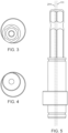
- the parts of the drive shaft 200 may be configured to have various cross-sectional shapes, such as, but not limited to, circular, triangular, square, pentagonal, hexagonal, heptagonal, octagonal, decagonal, dodecagonal, or another acceptable cross-sectional shape.
- the drive shaft 200 may have the same cross-sectional shape throughout, or the cross-sectional shape may vary throughout the drive shaft 200.
- the entire drive shaft 200 may have the same cross-sectional shape, one or more portions of the drive shaft 200 may have the same cross-sectional shape as another portion of the drive shaft, or none of the portions of the drive shaft may have the same cross-sectional shape as another portion of the drive shaft. Referring to Figs. 3 and 4 , for example, the aspects illustrated show portions of the drive shaft having circular and hexagonal cross sections.
- the drive shaft 200 may vary in size.
- the length of the drive shaft may be scalable.
- the drive shaft 200 may be at least about 1 mm long.
- the drive shaft may also be between about 1 mm long and about 1000 mm long. It may also be between about 1 mm long and about 500 mm long. It may also be between about 1 mm long and about 100 mm long. It may also be between about 1 mm long and about 50 mm long.
- the length of the drive shaft 200 may vary throughout. All sections of the drive shaft 200 may have about the same length, some sections of the drive shaft 200 may have about the same length as another section of the drive shaft, or none of the sections of the drive shaft 200 may have about the same length as any other section of the drive shaft.
- the diameter of the drive shaft 200 may be scalable.
- the diameter may be at least about 1 mm.
- the diameter may also be between about 1 mm and about 1000 mm.
- the diameter may also be between about 1 mm and 500 mm.
- the diameter may also be between about 1 mm and 100 mm.
- the diameter may also be between about 1 mm and 50 mm.
- the diameter of the drive shaft 200 may vary throughout. All sections of the drive shaft 200 may have about the same diameter, some sections of the drive shaft 200 may have about the same diameter as another section of the drive shaft, or none of the sections of the drive shaft 200 may have about the same diameter as any other section of the drive shaft.
- the drive shaft 200 may have additional features, such as notches, flanges, or engagement surfaces. Features may appear on any portion of the drive shaft 200.
- the input segment 206 may have additional features to engage an element.
- the input segment 206 may have one or more engagement surfaces 208.
- the input segment 206 may also have one or more retainer grooves 210 or 218.
- the input segment may also have additional features.
- the output segment 216 may have additional features.
- the output segment 216 may have one or more engagement surfaces 208.
- the output segment 216 may also have one or more retainer grooves 210 or 218.
- the output segment may also have additional features.
- the eccentric segment 214 of drive shaft 200 may have a circular cross section.
- the eccentric segment 214 may be cylindrical in shape.
- the outer surface of the eccentric segment 214 may be configured to slidably engage another portion of the reduction assembly.
- the eccentric segment 214 may be modified to improve engagement with another portion of the assembly.
- Methods of doing this include, but are not limited to, making the eccentric segment 214 out of material that has a low coefficient of friction when in contact with another surface, coating the eccentric segment 214 with a material that has a low coefficient of friction when in contact with another surface, applying a lubricant to either the eccentric segment, the contact surface, or both, positioning a plurality of ball bearings or similar structures between the eccentric segment and the other portion of the assembly, or any combination of approaches in this list.
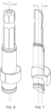
- the drive shaft 200 may have a plurality of axes running through it (for example, such as those illustrated in Figs. 5-7 ).
- a first axis 111 may run through at least a portion of the drive shaft 200.
- a second axis 211 may run through at least a different portion of the drive shaft 200.
- the second axis 211 may be parallel to the first axis 111.
- the second axis 211 may be positioned at a variety of acceptable distances away from the first axis 111.
- the second axis 211 may be positioned at least about 0.5 mm away from the first axis 111.
- the second axis 211 may be positioned at about 0.5 mm to about 500 mm away from the first axis 111.
- the second axis 211 may be positioned at about 0.5 mm to about 100 mm away from the first axis 111.
- the second axis 211 may be positioned at about 0.5 mm to about 50 mm from the first axis 111.
- the second axis 211 may be positioned at about 0.5 mm to about 10 mm from the first axis 111.
- Multiple portions of the drive shaft 200 may have centerlines lying on the same axis.
- the centerline of the input segment 206 and the centerline of the output segment 216 may each lie on the same axis.
- the centerline of the eccentric segment 214 may lie on a different axis.
- the drive shaft 200 may have other portions that have centerlines that lie on either the first axis 111, the second axis 211, or another acceptable axis.
- the centerline of the eccentric segment 214 may run along a second axis 211.
- the second axis may be parallel to the first axis 111.
- any portions of the drive shaft whose centerlines lie on the first axis will rotate around their centerlines; any portions whose centerlines do not lie on the first axis will still revolve around the first axis, but they will not rotate along their centerlines. If the drive shaft rotates around the first axis 111 and the eccentric segment 214 lies on the second axis 211, then the eccentric segment 214 will revolve around the first axis, but it will not rotate around its own center.
- the input segment 206 and the output segment 216 of the drive shaft 200 are aligned such that their centers have a centerline running along a same axis.
- the output segment 216 when the input segment 206 rotates around an axis running through its center, the output segment 216 also rotates around the same axis running through its center.
- the eccentric segment 214 is aligned such that its center has a centerline running along a second axis that is parallel to the first and is positioned a distance away from the first axis.
- the eccentric segment 214 is fixedly attached, either directly or through an intermediary, to the input segment 206 and the output segment 216. Because of this, the eccentric segment 214 revolves around the first axis and does not rotate around its own center.
- the reduction assembly includes a disk assembly 150.
- Disk assembly 150 includes at least one disk 152.
- the disk 152 may have a body 156 and a plurality of lobes 154.
- the lobes 154 may be positioned concentrically on the body 156.
- the disk 150 may have an opening 158 extending through the body 156.
- the opening 158 may be configured to slidably engage the eccentric segment 214 of the drive shaft 200.
- the disk assembly 150 may have a plurality of disks 152.
- a disk assembly 150 may include 1, 2, 3, 4, 5, or another acceptable number of disks 152.
- Disks 152 may vary in size.
- the disk may be at least about 0.5 mm at its widest point, it may be between about 0.5 mm and about 500 mm at its widest point, it may be between about 0.5 mm and about 100 mm at its widest point, it may be between about 0.5 mm and about 50 mm at its widest point, it may be between about 0.5 mm and about 10 mm at its widest point, or it may be another acceptable width.
- the disks may have various shapes (in the place perpendicular to the first axis 111).
- the disks may be oblong, circular, triangular, square, pentagonal, hexagonal, heptagonal, octagonal, or another suitable shape.
- the disk may include various materials, such as, but not limited to, metals, plastics, or a combination of metals and plastics. It may be made of metals, such as, but not limited to stainless steel, aluminum, or other metal alloys.
- plastics such as, but not limited to high-density polyethylene, low-density polyethylene, polyvinyl chloride, polypropylene, acrylonitrile butadiene styrene, polycarbonate, polyurethane, maleimide, bismaleimide, melamine formaldehyde, polyetheretherketone, polymethyl methacrylate, polytetrafluoroethylene, or a combination of one or more of plastics in this list.
- plastics such as, but not limited to high-density polyethylene, low-density polyethylene, polyvinyl chloride, polypropylene, acrylonitrile butadiene styrene, polycarbonate, polyurethane, maleimide, bismaleimide, melamine formaldehyde, polyetheretherketone, polymethyl methacrylate, polytetrafluoroethylene, or a combination of one or more of plastics in this list.
- Disk 152 has a plurality of lobes 154.
- the disk may have 2, 3, 4, 5, 6, 7, 8, 9, or more lobes.
- the lobes 154 may be positioned radially on the body of the disk such that they are equidistant from the disk's center.
- Lobes 154 may take a variety of shapes. Referring to Fig. 1 , the lobes 154 may be rounded. Alternatively, the lobes may be shaped to come to a pointed end. The lobes 154 may alternatively be shaped to come to a flat end. Lobes 154 may have other suitable shapes.
- each disk has a different number of lobes.
- the difference in number of lobes between adjacent disks may be 1, 2, 3, or another acceptable number.
- the difference in number of lobes between adjacent disks is 1.
- the disk assembly 150 has two disks 152. Referring to Figs. 1 and 2 , one of the two disks has four lobes, and the second disk has three lobes.
- the first disk has a cross-sectional shape (in the plane perpendicular to first axis 111) that is approximately square
- the second disk has a cross-sectional shape (in the plane perpendicular to first axis 111) that is approximately triangular.
- the disk assembly 150 has three disks 152.
- the three disks may have four lobes, three lobes, and two lobes, respectively.
- the disks may have five lobes, four lobes, and three lobes, respectively.
- each disk may have a different suitable number of lobes.
- the disks may be fixedly connected to one another.
- the disk assembly 150 may be a singular piece, or, in the alternative, it may be an assembly of separate pieces.
- the disks may be rotationally or slidably connected to one another.
- the disks may be disconnected from one another. In some aspects, some of the disks may be connected to one another while other disks are disconnected.
- the reduction assembly includes an upper housing 110 with a disk receptacle 132 and a lower housing 250.
- the disk receptacle 132 has a floor 139 and a wall 134.
- the wall 134 may have a plurality of protrusions 138 extending from the wall 134.
- the number of protrusions 138 may be equal to one more than the number of lobes on a disk 152.
- the protrusions on the wall may be various different shapes. In some aspects, the protrusions may be roller pins.
- the disk receptacle 132 may have an opening. The opening may engage the drive shaft 200.
- the disk receptacle may include various materials, such as, but not limited to, metals, plastics, or a combination of metals and plastics. It may be made of metals, such as, but not limited to stainless steel, aluminum, or other metal alloys. It may also be made of plastics, such as, but not limited to high-density polyethylene, low-density polyethylene, polyvinyl chloride, polypropylene, acrylonitrile butadiene styrene, polycarbonate, polyurethane, maleimide, bismaleimide, melamine formaldehyde, polyetheretherketone, polymethyl methacrylate, polytetrafluoroethylene, or a combination of one or more of plastics in this list.
- plastics such as, but not limited to high-density polyethylene, low-density polyethylene, polyvinyl chloride, polypropylene, acrylonitrile butadiene styrene, polycarbonate, polyurethane, maleimide
- the reduction assembly there are as many disk receptacles as there are disks in the disk assembly.
- a disk engages with a disk receptacle.
- the number of protrusions on the disk receptacle may be greater than the number of lobes on a disk engaging with the disk receptacle. In some aspects, the number of protrusions may be one greater than the number of lobes. Alternatively, the number of protrusions may be two greater than the number of lobes.
- Figs. 1 and 2 show two disks in a disk assembly. In this exemplar, there are also two disk receptacles.
- the first disk receptacle 132 has five protrusions 138 and is configured to engage with the first disk 152 that has four lobes 154.
- the second disk receptacle 256 has four protrusions 260 and is configured to engage with the second disk 170 that has three lobes 172.
- the first and second disks are conjoined and have a common opening 158.
- Protrusions may vary in shape and size. Protrusions may be formed from a continuous part of a disk receptacle. Alternatively, protrusions may be pins. In such implementations, the pins may rotate around their centers to facilitate engagement with the lobes of the disk.
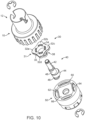
- aspects of another reduction assembly include an upper housing 10, disk assembly 30, drive shaft 40, and lower housing 50.
- the upper housing includes a tool engagement portion 12, an opening 14, and a disk receptacle 20.
- the disk receptacle 20 includes a floor 26, wall 22, and protrusion 24.
- Figs. 10 and 11 show a disk receptacle in the upper housing with five protrusions 24.
- the disk assembly 30 includes at least one disk 31.
- Disk 31 has a body 35, an opening 34, and lobes 32.
- the disk 31 in Fig. 14 has four lobes 32.
- Disk assembly 30 may include a plurality of disks.
- disk assembly 30 has two disks, disk 31 and disk 38.
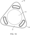
- Fig. 15 shows an aspect of disk 38.
- Disk 38 has body 37, opening 34, and lobes 39.
- Disk 39 shown in Fig. 15 has three lobes 39.
- the each disk in the plurality of disks in disk assembly 30 may be fixedly attached to another disk in the disk assembly.
- the plurality of disks may be one singular piece.
- each disk may be slidably or rotationally connected to at least one other disk. Referring to Figs. 10 and 11 , disk 31 and disk 38 are a singular piece and share an opening 34.
- the lower housing 50 includes an opening 54 and a disk receptacle 60.
- Disk receptacle 60 includes wall 62, floor 66, and protrusions 64.
- Figs. 10 and 11 shows a disk receptacle in the lower housing with four protrusions 64.
- the drive shaft 40 includes an input segment 42, an intermediate segment 48, an eccentric segment 44, and an output segment 46.
- the input segment 42 may be configured to pass through opening 34 of a disk in the disk assembly 30 and through the opening 14 in the upper housing and to attach to a tool (not shown).
- the output segment 46 may be configured to pass through an opening 54 in the lower housing 50.
- the eccentric segment 44 may be configured to pass through the opening 34 of a disk in disk assembly 30 and to slidably engage the disk assembly.
- the drive shaft may have additional features, such as, but not limited to, retainer grooves 204, 210, and 218.
- a disk engages with a disk receptacle.
- the disk is positioned on an eccentric segment of a drive shaft.
- the eccentric segment revolves around that center and does not rotate around its center.
- the disk positioned on the eccentric drive shaft similarly revolves around the center of the drive shaft.
- the lobes of the disk contact the protrusions of the disk receptacle. This may cause the disk to rotate around its center (and around the eccentric segment's center).
- the force exerted by the lobes of the disk on the protrusions of the disk receptacle may cause the disk receptacle to rotate.
- a reduction assembly may have multiple disks and disk receptacles. Each set of disk and disk receptacle may be fixedly connected to another set of disk and disk receptacle.
- the assembly includes an upper housing, drive shaft, disk, and lower housing ( Figs. 16-21 ).
- the upper housing 1001 has a tool engagement portion 1012, a disk receptacle 1020, and an opening 1014.
- the disk receptacle 1020 includes a floor 1026, a wall 1022, and protrusions 1024.
- the disk 1031 includes a body 1035, central opening 1034, peripheral openings 1036, and lobes 1032.
- the drive shaft 1040 includes an input segment 1042 and an eccentric segment 1044 a first axis 1111 and a second axis 1112. Referring to Fig.
- the lower housing 1050 includes a top surface 1052 and pins 1056.
- the input segment 1042 of the drive shaft 1040 may pass through the opening 1014 of the upper housing 1001 and may engage with a tool (not shown).
- the eccentric segment 1044 of the drive shaft 1040 may be configured to engage with the central opening 1034 of the disk 1031.
- the eccentric segment may slidably contact the disk while engaged in the central opening 1034 of the disk.
- the pins 1056 of the lower housing 1050 may engage with the peripheral openings 1036 of the disk.
- the lower housing may have a single pin 1056, or, alternatively the lower housing may have a plurality of pins 1056.
- the disk 1031 may have a single peripheral opening 1036, or, alternatively, the disk may have a plurality of peripheral openings 1036.
- the number of peripheral openings 1036 on the disk may be the same as the number of pins 1056 on the lower housing.
- the disk 1031 may have a single lobe 1032 or a plurality of lobes 1032.
- the disk receptacle 1020 in upper housing 1001 may have a plurality of protrusions 1024.
- the number of protrusions 1024 may be equal to one more than the number of lobes 1032 on the disk.
- the number of protrusions 1024 may be equal to two more or three more than the number of lobes 1032 on the disk.
- the difference in number of protrusions 1024 and number of lobes 1032 may be another acceptable number.
- the eccentric segment 1044 revolves around the center of the drive shaft, but not around the center of the eccentric segment. If the disk 1031 is engaged with the eccentric segment 1044, then the disk will also revolve around the center of the drive shaft.
- the lobes 1032 may engage the protrusions 1024 of the disk receptacle 1020 of the upper housing 1001. As the lobes engage the protrusions, the disk may rotate around its center. Alternatively, as the lobes engage the protrusions, the upper housing may rotate. Referring to Figs.
- the disk when the drive shaft rotates, the disk rotates around its center.
- the lobes 1032 of the disk engage with the protrusions 1024 of the disk receptacle.
- the disk 1031 may contact the top surface 1052 of the lower housing, or, alternatively, it may not contact the top surface 1052.
- the pins 1056 on the lower housing 1050 may engage with the peripheral openings 1036 of the disk 1031. In this aspect, as the disk 1031 rotates, the engagement between peripheral openings 1036 and pins 1056 creates forces acting on the pins and allows for rotation of the lower housing.
- the upper housing may be configured to attach to a tool at the engagement portion 1012, such as, but not limited to, a drill or another rotational tool.
- the upper housing may be part of a tool.
- the lower housing may also be configured to be attached to a tool, such as, but not limited to, a drill bit, cutting mechanism, velocity limiting device, torque limiting device, or another suitable tool.
- the lower housing may be part of a tool.
- a method of reducing rotational velocity includes connecting a rotational tool to a reduction assembly, such as one described herein, and then operating the rotational tool.
- the method may further include a step of disconnecting the rotational tool from the reduction assembly.
- the method may further include a step of disposing of the tool, the reduction assembly, or both after an acceptable number of uses or after an acceptable duration of use.
- the method may further include a step of connecting the reduction assembly to a second tool.
- the connection of the second tool may be made before connection of the first tool, after connection of the first tool, or while the first tool is connected. In some aspects, more tools may be connected in a variety of acceptable orders.
- the method may further include a step of connecting a torque limiting device to the reduction assembly.
- a reduction assembly as described herein may attach to a tool.
- a tool may attach to an upper housing, to a lower housing, or to both, either independently or simultaneously.
- a reduction assembly may be used to decrease the rotational speed of a tool.
- a drill may be attached to the reduction assembly.
- another suitable rotational tool may be attached to the reduction assembly.
- the tool may attach to an engagement surface of a drive shaft of the reduction assembly.
- the reduction assembly may attach to a tool at an output end of the assembly, such as, but not limited to, a lower housing of the assembly or a disk of the assembly.
- the tool may be a rotational tool. It may be an assembly for altering rotational speed of a device.
- the tool may be a drill. Further in some aspects, the tool may be a device for controlling torque.
- a reduction assembly as described herein may include an adaptor configured to connect to at least one output device.
- An output device may be a device for controlling torque.
- a reduction assembly unit may include an upper housing 3001, a drive shaft 3040, a disk assembly 3030 having a first disk 3031 and a second disk 3038 and an opening 3034 through the conjoined first and second disk, and a lower housing 3050.
- the drive shaft 3040 has a motor output interface 3014 in an input segment 3042 to accept a motor output and an eccentric segment 3044.
- the eccentric segment 3044 may be configured to pass through the opening 3034 of the disk assembly 3030 and to slidably engage the disk assembly.
- the lower housing 3050 provides an adapter interface 3052 and may include a disk receptacle 3060 with protrusions 3064 to help connect the reduction assembly to an output device, such as, but not limited to, the adaptor 3076 in the adapter interface 3052.
- the adapter can mate with a torque limiting device via an interface 3111, a retainer ring 3074, and a washer 3072 are added to assemble the reduction assembly unit 3000.
- the reduction assembly may include multiples of each element as needed in various implementations.
- a reduction assembly may include a plurality of disks. Referring to Figs. 23-27 , a reduction assembly may include two disks. The assembly may include a first disk 3031 and a second disk 3038. First disk 3031 may have three lobes 3032. Second disk 3038 may have two lobes 3039.
- An upper housing 3001 may have a first disk receptacle. The first disk receptacle in the upper housing may have protrusions (not shown) that engage with the first disk 3031. The disk receptacle not shown may be configured as the disk receptacle 132 with a floor 139 and a wall 134 shown in figure 2 .
- the first disk receptacle in the upper housing may have four protrusions.
- the lower housing 3050 may have a second disk receptacle 3060.
- the second disk receptacle may have three protrusions 3064 that engage with the lobes of the second disk 3038.
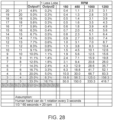
- Table 1 shows reduced output rotations based on input rotations and a correlation to lobe numbers.
- Figure 28 shows the change in output at various RPM when the active lobe number is reduced.
Landscapes
- Engineering & Computer Science (AREA)
- General Engineering & Computer Science (AREA)
- Mechanical Engineering (AREA)
- Transmission Devices (AREA)
- Surgical Instruments (AREA)
- Connection Of Motors, Electrical Generators, Mechanical Devices, And The Like (AREA)
Claims (10)
- Hypozykloide Untersetzungsbaugruppe, umfassend:ein oberes Gehäuse (110), das einen Deckabschnitt (118) und einen Bodenabschnitt (116) aufweist, wobei der Deckabschnitt (118) eine erste Öffnung (135) aufweist und der Bodenabschnitt (116) eine zweite Öffnung (136) aufweist, die erste Öffnung (135) und die zweite Öffnung (136) einen Durchlass (137) durch den Deckabschnitt (118) und den Bodenabschnitt (116) definieren, der Durchlass (137) sich entlang einer ersten Achse (11) erstreckt;der Deckabschnitt (118) dazu ausgelegt ist, mit einem Werkzeug einzugreifen;der Bodenabschnitt (116) eine Innenoberfläche (130) und eine Außenoberfläche (112) aufweist, wobei die Innenoberfläche (130) einen Scheibenbehälter (132) aufweist;eine Antriebswelle (200), die ein Decksegment (206), ein mittleres Segment (214) und ein unteres Segment (216) aufweist;das Decksegment (206) dazu ausgelegt ist, durch den Auslass (137) des oberen Gehäuses (110) zu gehen und mit dem Werkzeug zu interagieren, wobei das Decksegment (206) einen ersten Durchmesser (D1) aufweist und eine Mittellinie aufweist, die mit der ersten Achse (111) ausgerichtet ist;das mittlere Segment (214) einen zweiten Durchmesser (D2) aufweist, der größer als der erste Durchmesser (D1) ist und eine Mittellinie aufweist, die mit einer zweiten Achse (211) ausgerichtet ist, wobei die zweite Achse (211) parallel zu der ersten Achse (111) ist und bei einem ersten Abstand von der ersten Achse (111) positioniert ist;das untere Segment (216) einen dritten Durchmesser (D3) aufweist, der geringer als der zweite Durchmesser (D2) ist und eine Mittellinie aufweist, die mit der ersten Achse (111) ausgerichtet ist;eine Scheibenbaugruppe (150);dadurch gekennzeichnet, dass die Scheibenbaugruppe Folgendes umfasst:eine Vielzahl von Scheiben (152), die jeweils einen Körper (156) und eine Vielzahl von Nocken (154) radial um den Körper (156) positioniert aufweisen, wobei Nocken (154) dazu ausgelegt sind, mit der Scheibenaufnahme (132) in dem oberen Gehäuse (110) einzugreifen, der Körper (156) eine Öffnung (158) aufweist, die sich durch diesen erstreckt, die Öffnung (158) dazu ausgelegt ist, mit dem mittleren Segment (214) der Antriebswelle (200) einzugreifen; undein unteres Gehäuse (250), das dazu ausgelegt ist, mit dem unteren Segment (216) der Antriebswelle (200) einzugreifen, wobei das untere Gehäuse (250) weiter eine Scheibenaufnahme (132) umfasst, die dazu ausgelegt ist, mit einer der Vielzahl von Scheiben (152) einzugreifen.
- Untersetzungsbaugruppe nach Anspruch 1, wobei jede Scheibe (152) der Vielzahl von Scheiben (152) eine unterschiedliche Anzahl von Nocken (154) aufweist.
- Untersetzungsbaugruppe nach Anspruch 1, wobei die Vielzahl von Scheiben (152) drei Scheiben (152) beträgt.
- Untersetzungsbaugruppe nach Anspruch 1, wobei die Vielzahl von Scheiben (152) zwei Scheiben (152) beträgt.
- Untersetzungsbaugruppe nach Anspruch 4, wobei die erste der zwei Scheiben (152) vier Nocken (154) aufweist und die zweite der zwei Scheiben (152) drei Nocken (154) aufweist.
- Untersetzungsbaugruppe nach Anspruch 1, wobei die Scheibenaufnahme (132) eine Vielzahl von Fortsätzen (138) umfasst, die radial um die Mitte der Aufnahme (132) positioniert sind, wobei die Anzahl von Fortsätzen (138) gleich der Anzahl von Nocken (154) der Scheibe (152) plus Eins ist.
- Untersetzungsbaugruppe nach Anspruch 1, wobei das untere Gehäuse (250) als Teil einer Drehmomentbegrenzungsausgabevorrichtung gebildet ist.
- Untersetzungsbaugruppe nach Anspruch 1, wobei das Werkzeug ein Bohrer ist.
- Verfahren zum Untersetzen von Drehgeschwindigkeit eines Werkzeugs, umfassend:Eingreifenlassen eines Eingabewerkzeugs mit einer Untersetzungsbaugruppe nach Anspruch 1;wobei die Untersetzungsbaugruppe eine Antriebswelle (200), eine Scheibe (152), eine Scheibenaufnahme (132), die dazu ausgelegt ist, mit der Scheibe einzugreifen, und ein Ausgabesegment (216) umfasst; undBetreiben des Werkzeugs derart, dass das Ausgabesegment (216) der Untersetzungsbaugruppe bei einer niedrigeren Geschwindigkeit als das Eingabewerkzeug rotiert.
- Verfahren zum Untersetzen von Drehgeschwindigkeit eines Werkzeugs nach Anspruch 9, das weiter einen Schritt zum Lösen des Werkzeugs von der Untersetzungsbaugruppe umfasst.
Applications Claiming Priority (3)
| Application Number | Priority Date | Filing Date | Title |
|---|---|---|---|
| US201662381497P | 2016-08-30 | 2016-08-30 | |
| US201662381491P | 2016-08-30 | 2016-08-30 | |
| PCT/US2017/014970 WO2018044343A1 (en) | 2016-08-30 | 2017-01-25 | Hypocycloid speed buffer |
Publications (3)
| Publication Number | Publication Date |
|---|---|
| EP3507523A1 EP3507523A1 (de) | 2019-07-10 |
| EP3507523A4 EP3507523A4 (de) | 2020-07-08 |
| EP3507523B1 true EP3507523B1 (de) | 2023-05-10 |
Family
ID=61301226
Family Applications (2)
| Application Number | Title | Priority Date | Filing Date |
|---|---|---|---|
| EP17847106.6A Active EP3507522B1 (de) | 2016-08-30 | 2017-01-25 | Hypozykloidvorrichtung |
| EP17847107.4A Active EP3507523B1 (de) | 2016-08-30 | 2017-01-25 | Hypozykloidischer geschwindigkeitspuffer |
Family Applications Before (1)
| Application Number | Title | Priority Date | Filing Date |
|---|---|---|---|
| EP17847106.6A Active EP3507522B1 (de) | 2016-08-30 | 2017-01-25 | Hypozykloidvorrichtung |
Country Status (4)
| Country | Link |
|---|---|
| US (1) | US11441642B2 (de) |
| EP (2) | EP3507522B1 (de) |
| CA (2) | CA3031636C (de) |
| WO (2) | WO2018044342A1 (de) |
Families Citing this family (8)
| Publication number | Priority date | Publication date | Assignee | Title |
|---|---|---|---|---|
| EP3653905B1 (de) * | 2018-11-13 | 2021-06-09 | maxon international ag | Exzentergetriebe |
| NO20190132A1 (no) | 2019-01-31 | 2020-08-03 | Tocircle Ind As | Transmisjon |
| IT201900004871A1 (it) * | 2019-04-01 | 2020-10-01 | Omme Gears S A S | Riduttore cicloidale |
| JP2022536416A (ja) | 2019-06-13 | 2022-08-16 | サーキュラー ウェーブ ドライブ パートナーズ インコーポレイテッド | 円形波動ドライブ |
| US11647699B2 (en) * | 2019-10-15 | 2023-05-16 | Dinotooth Cutter, LLC | Tree saw |
| WO2021201898A1 (en) | 2020-03-31 | 2021-10-07 | Circular Wave Drive Partners Inc. | Circular wave drive |
| WO2022076895A1 (en) | 2020-10-09 | 2022-04-14 | Milwaukee Electric Tool Corporation | Clutch socket adapter for a tool |
| CN113236716B (zh) * | 2021-04-16 | 2021-11-23 | 东北石油大学 | 一种基于内摆线啮合原理的用于油井的减速机 |
Family Cites Families (45)
| Publication number | Priority date | Publication date | Assignee | Title |
|---|---|---|---|---|
| US4316439A (en) * | 1969-03-10 | 1982-02-23 | Tyree Joe W | Rotary engine with internal or external pressure cycle |
| US3695059A (en) | 1971-01-14 | 1972-10-03 | Wilburn B Laubach | Adjustable torque limiting coupling |
| DE2427352A1 (de) | 1974-06-06 | 1975-12-18 | Ulrich Schmidt | Vorsatzschraubendreher |
| US3998112A (en) * | 1974-12-06 | 1976-12-21 | Compudrive Corporation | Mechanical drives |
| US4177695A (en) * | 1975-06-04 | 1979-12-11 | Grove Leslie H | Rotary speed changer |
| US4643047A (en) * | 1981-10-20 | 1987-02-17 | Advanced Energy Concepts '81 Ltd. | Speed reducing gearing mechanism employing trochoidally formed gear surfaces for rolling torque transmission |
| JPH0762495B2 (ja) | 1985-06-27 | 1995-07-05 | 加茂精工株式会社 | 転動ボ−ル形差動減速機構 |
| CN1007545B (zh) * | 1985-08-24 | 1990-04-11 | 沈培基 | 摆线等距线齿轮传动副及其装置 |
| JP2966536B2 (ja) * | 1990-12-27 | 1999-10-25 | 加茂精工株式会社 | 転動ボール形差動減速装置 |
| US5145468A (en) * | 1991-01-07 | 1992-09-08 | Compudrive Corporation | Adjustable cycloidal speed reducer |
| JPH08142Y2 (ja) | 1991-03-26 | 1996-01-10 | 株式会社マイティエンジニアリング | トルク制限型の回転力伝達部材 |
| JPH0926011A (ja) * | 1995-07-12 | 1997-01-28 | Kamo Seiko Kk | 転動ボール式変速装置 |
| US6132435A (en) | 1999-09-14 | 2000-10-17 | Synthes (Usa) | Torque limiting device for surgical use |
| SE9903639L (sv) | 1999-10-11 | 2000-09-18 | Kapman Ab | Momentbegränsad skruvmejsel |
| EP1110512A1 (de) | 1999-12-20 | 2001-06-27 | Sulzer Orthopedics Ltd. | Medizinaltechnische Werkzeughaltevorrichtung mit Drehmomentbegrenzung |
| US6745812B1 (en) * | 2003-02-24 | 2004-06-08 | Tai-Ping Liu | Hypocycloid drive device for adjusting slat angles for a venetian blind |
| DE10341697B3 (de) | 2003-09-10 | 2004-10-07 | Felo-Werkzeugfabrik Holland-Letz Gmbh | Schraubwerkzeug mit einer Vorrichtung zur Begrenzung des übertragenen Drehmomentes |
| US7343824B2 (en) | 2006-06-20 | 2008-03-18 | Bradshaw Medical, Inc. | Variable torque-limiting driver |
| US20080015034A1 (en) | 2006-07-17 | 2008-01-17 | Deere & Company, A Delaware Corporation | Torque limiter for a harvester row unit |
| US7766750B2 (en) | 2006-10-17 | 2010-08-03 | Jlg Industries, Inc. | Slip clutch |
| US8221431B2 (en) | 2006-12-18 | 2012-07-17 | Greatbatch Medical S.A. | Calibrated mechanical orthopedic driver with wear-compensated torque-limiting mechanism |
| EA015293B1 (ru) * | 2007-07-09 | 2011-06-30 | Закрытое Акционерное Общество "Технология Маркет" | Зубчатое зацепление колес (варианты) и планетарный зубчатый механизм на его основе (варианты) |
| US7762164B2 (en) | 2008-06-02 | 2010-07-27 | Eca Medical Instruments | Torque-limiting device |
| JP4814351B2 (ja) * | 2009-02-23 | 2011-11-16 | 加茂精工株式会社 | 転動ボール式二段低変速装置 |
| US8161849B2 (en) | 2009-07-06 | 2012-04-24 | Michael Curt Walter Stark | Torque limiter |
| TW201109127A (en) | 2009-09-15 | 2011-03-16 | Jin-Tan Huang | Torque adjuster |
| EP2566412B1 (de) | 2010-05-06 | 2020-05-06 | ECA Medical Instruments | In einer kanüle befindliche vorrichtung mit ultrahohem drehmoment |
| WO2011139902A2 (en) | 2010-05-06 | 2011-11-10 | Eca Medical Instruments | Ultra high torque device |
| US8365641B2 (en) | 2010-05-12 | 2013-02-05 | Terry Daglow | Torque wrench |
| US9162350B2 (en) | 2010-07-28 | 2015-10-20 | Eca Medical Instruments | Robust nose torque-limiting device |
| EP2598293B1 (de) | 2010-07-28 | 2020-07-01 | ECA Medical Instruments | Kanülierte drehmomentvorrichtung und spitzenrastung |
| US8297171B2 (en) | 2010-08-09 | 2012-10-30 | Ben Gagnon | Torque limiter for a gun turret |
| US8714056B2 (en) | 2010-09-03 | 2014-05-06 | Greatbatch Ltd. | Torque limiting mechanism with lock bushing |
| US9868194B2 (en) | 2011-11-30 | 2018-01-16 | Eca Medical Instruments | Reversible multiple use disposable torque limiting device |
| TWM439546U (en) | 2012-06-29 | 2012-10-21 | Wei-Chieh Chuang | Non-return ratchet type torque socket |
| EP2948077B1 (de) | 2013-01-23 | 2020-04-29 | ECA Medical Instruments | Verstärkte kunststoffverbinderhalterung für einwegvorrichtungen |
| EP2948093B1 (de) | 2013-01-23 | 2019-04-10 | ECA Medical Instruments | Einweg-inline-drehmomentbegrenzungsvorrichtung für einen stromantrieb |
| US9217492B2 (en) * | 2013-11-22 | 2015-12-22 | Techtronic Power Tools Technology Limited | Multi-speed cycloidal transmission |
| TWM473901U (zh) | 2013-12-03 | 2014-03-11 | xiu-mei Chen | 電動手工具之轉接頭構造 |
| WO2015153376A1 (en) | 2014-04-01 | 2015-10-08 | Eca Medical Instruments | Fortified high torque device |
| US10422414B2 (en) * | 2015-04-14 | 2019-09-24 | Delta Electronics, Inc. | Speed reducer |
| WO2017062651A1 (en) | 2015-10-07 | 2017-04-13 | Eca Medical Instruments | Gearless spring washer high torque device |
| US10343269B2 (en) * | 2015-10-07 | 2019-07-09 | Eca Medical Instruments | Hypocycloid reduction gearless spring washer torque limiting device |
| WO2017062070A1 (en) | 2015-10-07 | 2017-04-13 | Eca Medical Instruments | Gearless compact torque drive |
| US10610429B2 (en) * | 2016-06-29 | 2020-04-07 | Stryker Corporation | Rotary actuator having clutch assembly for use with patient support apparatus |
-
2017
- 2017-01-25 WO PCT/US2017/014967 patent/WO2018044342A1/en unknown
- 2017-01-25 US US16/337,909 patent/US11441642B2/en active Active
- 2017-01-25 WO PCT/US2017/014970 patent/WO2018044343A1/en unknown
- 2017-01-25 EP EP17847106.6A patent/EP3507522B1/de active Active
- 2017-01-25 CA CA3031636A patent/CA3031636C/en active Active
- 2017-01-25 CA CA3035010A patent/CA3035010C/en active Active
- 2017-01-25 EP EP17847107.4A patent/EP3507523B1/de active Active
Also Published As
| Publication number | Publication date |
|---|---|
| US20200011400A1 (en) | 2020-01-09 |
| EP3507523A4 (de) | 2020-07-08 |
| EP3507522A1 (de) | 2019-07-10 |
| US11441642B2 (en) | 2022-09-13 |
| CA3035010A1 (en) | 2018-03-08 |
| WO2018044343A1 (en) | 2018-03-08 |
| WO2018044342A1 (en) | 2018-03-08 |
| EP3507522A4 (de) | 2020-07-08 |
| EP3507522B1 (de) | 2022-12-14 |
| CA3035010C (en) | 2024-01-30 |
| CA3031636A1 (en) | 2018-03-08 |
| EP3507523A1 (de) | 2019-07-10 |
| CA3031636C (en) | 2024-01-30 |
Similar Documents
| Publication | Publication Date | Title |
|---|---|---|
| EP3507523B1 (de) | Hypozykloidischer geschwindigkeitspuffer | |
| EP2895036B1 (de) | Drehbares antriebselement zum bewegen einer fensterabdeckung | |
| US10343269B2 (en) | Hypocycloid reduction gearless spring washer torque limiting device | |
| CN104879375B (zh) | 具有中心插入件的组合式轴 | |
| EP1932608A1 (de) | Bohrer/Treiber | |
| US20110220453A1 (en) | Continuous variable clutch | |
| CN206588875U (zh) | 旋转式紧固装置 | |
| US20060068962A1 (en) | Control units | |
| KR20110068500A (ko) | 다축 싸이클로이드 감속기 | |
| US11511407B2 (en) | Single use integrated speed reduction and gearless device | |
| CN209255906U (zh) | 简易的摩擦轮无级变速手摇钻 | |
| CN109366519B (zh) | 一种用于主操作手的阻尼关节 | |
| US10634218B2 (en) | Multiplying nested gearbox | |
| US6348022B1 (en) | Planetary gear transmission apparatus | |
| CN110454518A (zh) | 一种水钻机的离合器 | |
| CN113144513A (zh) | 一种可调式哑铃 | |
| KR20170063443A (ko) | 원형 파 드라이브 | |
| AU1140400A (en) | Multiple speed orbital transmission | |
| CN112709767A (zh) | 扭矩调节机构及电动螺丝刀 | |
| WO2017074478A1 (en) | Circular wave drive | |
| US11306801B2 (en) | Single use gear reduction device | |
| CN210704826U (zh) | 一种轴向调节机构以及爬行机器人 | |
| CN217081085U (zh) | 一种高稳定性空心长轴 | |
| CN217794269U (zh) | 一种带吊环的门上单杠 | |
| CN213957058U (zh) | 测试装置 |
Legal Events
| Date | Code | Title | Description |
|---|---|---|---|
| STAA | Information on the status of an ep patent application or granted ep patent |
Free format text: STATUS: THE INTERNATIONAL PUBLICATION HAS BEEN MADE |
|
| PUAI | Public reference made under article 153(3) epc to a published international application that has entered the european phase |
Free format text: ORIGINAL CODE: 0009012 |
|
| STAA | Information on the status of an ep patent application or granted ep patent |
Free format text: STATUS: REQUEST FOR EXAMINATION WAS MADE |
|
| 17P | Request for examination filed |
Effective date: 20190123 |
|
| AK | Designated contracting states |
Kind code of ref document: A1 Designated state(s): AL AT BE BG CH CY CZ DE DK EE ES FI FR GB GR HR HU IE IS IT LI LT LU LV MC MK MT NL NO PL PT RO RS SE SI SK SM TR |
|
| AX | Request for extension of the european patent |
Extension state: BA ME |
|
| DAV | Request for validation of the european patent (deleted) | ||
| DAX | Request for extension of the european patent (deleted) | ||
| A4 | Supplementary search report drawn up and despatched |
Effective date: 20200609 |
|
| RIC1 | Information provided on ipc code assigned before grant |
Ipc: F16H 49/00 20060101ALI20200604BHEP Ipc: F16H 1/32 20060101ALI20200604BHEP Ipc: F16H 1/28 20060101AFI20200604BHEP Ipc: F16H 25/06 20060101ALI20200604BHEP Ipc: F16H 1/30 20060101ALI20200604BHEP Ipc: F16H 1/34 20060101ALI20200604BHEP |
|
| STAA | Information on the status of an ep patent application or granted ep patent |
Free format text: STATUS: EXAMINATION IS IN PROGRESS |
|
| RAP3 | Party data changed (applicant data changed or rights of an application transferred) |
Owner name: ECA MEDICAL INSTRUMENTS |
|
| 17Q | First examination report despatched |
Effective date: 20210503 |
|
| STAA | Information on the status of an ep patent application or granted ep patent |
Free format text: STATUS: EXAMINATION IS IN PROGRESS |
|
| GRAP | Despatch of communication of intention to grant a patent |
Free format text: ORIGINAL CODE: EPIDOSNIGR1 |
|
| STAA | Information on the status of an ep patent application or granted ep patent |
Free format text: STATUS: GRANT OF PATENT IS INTENDED |
|
| INTG | Intention to grant announced |
Effective date: 20221125 |
|
| GRAS | Grant fee paid |
Free format text: ORIGINAL CODE: EPIDOSNIGR3 |
|
| GRAA | (expected) grant |
Free format text: ORIGINAL CODE: 0009210 |
|
| STAA | Information on the status of an ep patent application or granted ep patent |
Free format text: STATUS: THE PATENT HAS BEEN GRANTED |
|
| AK | Designated contracting states |
Kind code of ref document: B1 Designated state(s): AL AT BE BG CH CY CZ DE DK EE ES FI FR GB GR HR HU IE IS IT LI LT LU LV MC MK MT NL NO PL PT RO RS SE SI SK SM TR |
|
| REG | Reference to a national code |
Ref country code: GB Ref legal event code: FG4D |
|
| REG | Reference to a national code |
Ref country code: AT Ref legal event code: REF Ref document number: 1566952 Country of ref document: AT Kind code of ref document: T Effective date: 20230515 Ref country code: CH Ref legal event code: EP |
|
| REG | Reference to a national code |
Ref country code: DE Ref legal event code: R096 Ref document number: 602017068710 Country of ref document: DE |
|
| REG | Reference to a national code |
Ref country code: IE Ref legal event code: FG4D |
|
| REG | Reference to a national code |
Ref country code: LT Ref legal event code: MG9D |
|
| REG | Reference to a national code |
Ref country code: NL Ref legal event code: MP Effective date: 20230510 |
|
| REG | Reference to a national code |
Ref country code: AT Ref legal event code: MK05 Ref document number: 1566952 Country of ref document: AT Kind code of ref document: T Effective date: 20230510 |
|
| PG25 | Lapsed in a contracting state [announced via postgrant information from national office to epo] |
Ref country code: SE Free format text: LAPSE BECAUSE OF FAILURE TO SUBMIT A TRANSLATION OF THE DESCRIPTION OR TO PAY THE FEE WITHIN THE PRESCRIBED TIME-LIMIT Effective date: 20230510 Ref country code: PT Free format text: LAPSE BECAUSE OF FAILURE TO SUBMIT A TRANSLATION OF THE DESCRIPTION OR TO PAY THE FEE WITHIN THE PRESCRIBED TIME-LIMIT Effective date: 20230911 Ref country code: NO Free format text: LAPSE BECAUSE OF FAILURE TO SUBMIT A TRANSLATION OF THE DESCRIPTION OR TO PAY THE FEE WITHIN THE PRESCRIBED TIME-LIMIT Effective date: 20230810 Ref country code: NL Free format text: LAPSE BECAUSE OF FAILURE TO SUBMIT A TRANSLATION OF THE DESCRIPTION OR TO PAY THE FEE WITHIN THE PRESCRIBED TIME-LIMIT Effective date: 20230510 Ref country code: ES Free format text: LAPSE BECAUSE OF FAILURE TO SUBMIT A TRANSLATION OF THE DESCRIPTION OR TO PAY THE FEE WITHIN THE PRESCRIBED TIME-LIMIT Effective date: 20230510 Ref country code: AT Free format text: LAPSE BECAUSE OF FAILURE TO SUBMIT A TRANSLATION OF THE DESCRIPTION OR TO PAY THE FEE WITHIN THE PRESCRIBED TIME-LIMIT Effective date: 20230510 |
|
| PG25 | Lapsed in a contracting state [announced via postgrant information from national office to epo] |
Ref country code: RS Free format text: LAPSE BECAUSE OF FAILURE TO SUBMIT A TRANSLATION OF THE DESCRIPTION OR TO PAY THE FEE WITHIN THE PRESCRIBED TIME-LIMIT Effective date: 20230510 Ref country code: PL Free format text: LAPSE BECAUSE OF FAILURE TO SUBMIT A TRANSLATION OF THE DESCRIPTION OR TO PAY THE FEE WITHIN THE PRESCRIBED TIME-LIMIT Effective date: 20230510 Ref country code: LV Free format text: LAPSE BECAUSE OF FAILURE TO SUBMIT A TRANSLATION OF THE DESCRIPTION OR TO PAY THE FEE WITHIN THE PRESCRIBED TIME-LIMIT Effective date: 20230510 Ref country code: LT Free format text: LAPSE BECAUSE OF FAILURE TO SUBMIT A TRANSLATION OF THE DESCRIPTION OR TO PAY THE FEE WITHIN THE PRESCRIBED TIME-LIMIT Effective date: 20230510 Ref country code: IS Free format text: LAPSE BECAUSE OF FAILURE TO SUBMIT A TRANSLATION OF THE DESCRIPTION OR TO PAY THE FEE WITHIN THE PRESCRIBED TIME-LIMIT Effective date: 20230910 Ref country code: HR Free format text: LAPSE BECAUSE OF FAILURE TO SUBMIT A TRANSLATION OF THE DESCRIPTION OR TO PAY THE FEE WITHIN THE PRESCRIBED TIME-LIMIT Effective date: 20230510 Ref country code: GR Free format text: LAPSE BECAUSE OF FAILURE TO SUBMIT A TRANSLATION OF THE DESCRIPTION OR TO PAY THE FEE WITHIN THE PRESCRIBED TIME-LIMIT Effective date: 20230811 |
|
| PG25 | Lapsed in a contracting state [announced via postgrant information from national office to epo] |
Ref country code: FI Free format text: LAPSE BECAUSE OF FAILURE TO SUBMIT A TRANSLATION OF THE DESCRIPTION OR TO PAY THE FEE WITHIN THE PRESCRIBED TIME-LIMIT Effective date: 20230510 |
|
| PG25 | Lapsed in a contracting state [announced via postgrant information from national office to epo] |
Ref country code: SK Free format text: LAPSE BECAUSE OF FAILURE TO SUBMIT A TRANSLATION OF THE DESCRIPTION OR TO PAY THE FEE WITHIN THE PRESCRIBED TIME-LIMIT Effective date: 20230510 |
|
| PGFP | Annual fee paid to national office [announced via postgrant information from national office to epo] |
Ref country code: GB Payment date: 20231207 Year of fee payment: 8 |
|
| PG25 | Lapsed in a contracting state [announced via postgrant information from national office to epo] |
Ref country code: SM Free format text: LAPSE BECAUSE OF FAILURE TO SUBMIT A TRANSLATION OF THE DESCRIPTION OR TO PAY THE FEE WITHIN THE PRESCRIBED TIME-LIMIT Effective date: 20230510 Ref country code: SK Free format text: LAPSE BECAUSE OF FAILURE TO SUBMIT A TRANSLATION OF THE DESCRIPTION OR TO PAY THE FEE WITHIN THE PRESCRIBED TIME-LIMIT Effective date: 20230510 Ref country code: RO Free format text: LAPSE BECAUSE OF FAILURE TO SUBMIT A TRANSLATION OF THE DESCRIPTION OR TO PAY THE FEE WITHIN THE PRESCRIBED TIME-LIMIT Effective date: 20230510 Ref country code: EE Free format text: LAPSE BECAUSE OF FAILURE TO SUBMIT A TRANSLATION OF THE DESCRIPTION OR TO PAY THE FEE WITHIN THE PRESCRIBED TIME-LIMIT Effective date: 20230510 Ref country code: DK Free format text: LAPSE BECAUSE OF FAILURE TO SUBMIT A TRANSLATION OF THE DESCRIPTION OR TO PAY THE FEE WITHIN THE PRESCRIBED TIME-LIMIT Effective date: 20230510 Ref country code: CZ Free format text: LAPSE BECAUSE OF FAILURE TO SUBMIT A TRANSLATION OF THE DESCRIPTION OR TO PAY THE FEE WITHIN THE PRESCRIBED TIME-LIMIT Effective date: 20230510 |
|
| PGFP | Annual fee paid to national office [announced via postgrant information from national office to epo] |
Ref country code: FR Payment date: 20231212 Year of fee payment: 8 |
|
| REG | Reference to a national code |
Ref country code: DE Ref legal event code: R097 Ref document number: 602017068710 Country of ref document: DE |
|
| PLBE | No opposition filed within time limit |
Free format text: ORIGINAL CODE: 0009261 |
|
| STAA | Information on the status of an ep patent application or granted ep patent |
Free format text: STATUS: NO OPPOSITION FILED WITHIN TIME LIMIT |
|
| 26N | No opposition filed |
Effective date: 20240213 |
|
| PGFP | Annual fee paid to national office [announced via postgrant information from national office to epo] |
Ref country code: DE Payment date: 20231205 Year of fee payment: 8 |
|
| PG25 | Lapsed in a contracting state [announced via postgrant information from national office to epo] |
Ref country code: SI Free format text: LAPSE BECAUSE OF FAILURE TO SUBMIT A TRANSLATION OF THE DESCRIPTION OR TO PAY THE FEE WITHIN THE PRESCRIBED TIME-LIMIT Effective date: 20230510 |