EP3506987B1 - Flame cell and a flame arrestor comprising the flame cell - Google Patents
Flame cell and a flame arrestor comprising the flame cell Download PDFInfo
- Publication number
- EP3506987B1 EP3506987B1 EP17768540.1A EP17768540A EP3506987B1 EP 3506987 B1 EP3506987 B1 EP 3506987B1 EP 17768540 A EP17768540 A EP 17768540A EP 3506987 B1 EP3506987 B1 EP 3506987B1
- Authority
- EP
- European Patent Office
- Prior art keywords
- flame
- cell
- channels
- arrestor
- flame cell
- Prior art date
- Legal status (The legal status is an assumption and is not a legal conclusion. Google has not performed a legal analysis and makes no representation as to the accuracy of the status listed.)
- Active
Links
Images






Classifications
-
- A—HUMAN NECESSITIES
- A62—LIFE-SAVING; FIRE-FIGHTING
- A62C—FIRE-FIGHTING
- A62C4/00—Flame traps allowing passage of gas but not of flame or explosion wave
-
- A—HUMAN NECESSITIES
- A62—LIFE-SAVING; FIRE-FIGHTING
- A62C—FIRE-FIGHTING
- A62C3/00—Fire prevention, containment or extinguishing specially adapted for particular objects or places
- A62C3/06—Fire prevention, containment or extinguishing specially adapted for particular objects or places of highly inflammable material, e.g. light metals, petroleum products
- A62C3/065—Fire prevention, containment or extinguishing specially adapted for particular objects or places of highly inflammable material, e.g. light metals, petroleum products for containers filled with inflammable liquids
-
- A—HUMAN NECESSITIES
- A62—LIFE-SAVING; FIRE-FIGHTING
- A62C—FIRE-FIGHTING
- A62C4/00—Flame traps allowing passage of gas but not of flame or explosion wave
- A62C4/02—Flame traps allowing passage of gas but not of flame or explosion wave in gas-pipes
-
- B—PERFORMING OPERATIONS; TRANSPORTING
- B33—ADDITIVE MANUFACTURING TECHNOLOGY
- B33Y—ADDITIVE MANUFACTURING, i.e. MANUFACTURING OF THREE-DIMENSIONAL [3D] OBJECTS BY ADDITIVE DEPOSITION, ADDITIVE AGGLOMERATION OR ADDITIVE LAYERING, e.g. BY 3D PRINTING, STEREOLITHOGRAPHY OR SELECTIVE LASER SINTERING
- B33Y10/00—Processes of additive manufacturing
-
- B—PERFORMING OPERATIONS; TRANSPORTING
- B33—ADDITIVE MANUFACTURING TECHNOLOGY
- B33Y—ADDITIVE MANUFACTURING, i.e. MANUFACTURING OF THREE-DIMENSIONAL [3D] OBJECTS BY ADDITIVE DEPOSITION, ADDITIVE AGGLOMERATION OR ADDITIVE LAYERING, e.g. BY 3D PRINTING, STEREOLITHOGRAPHY OR SELECTIVE LASER SINTERING
- B33Y80/00—Products made by additive manufacturing
-
- F—MECHANICAL ENGINEERING; LIGHTING; HEATING; WEAPONS; BLASTING
- F17—STORING OR DISTRIBUTING GASES OR LIQUIDS
- F17C—VESSELS FOR CONTAINING OR STORING COMPRESSED, LIQUEFIED OR SOLIDIFIED GASES; FIXED-CAPACITY GAS-HOLDERS; FILLING VESSELS WITH, OR DISCHARGING FROM VESSELS, COMPRESSED, LIQUEFIED, OR SOLIDIFIED GASES
- F17C13/00—Details of vessels or of the filling or discharging of vessels
- F17C13/12—Arrangements or mounting of devices for preventing or minimising the effect of explosion ; Other safety measures
-
- B—PERFORMING OPERATIONS; TRANSPORTING
- B32—LAYERED PRODUCTS
- B32B—LAYERED PRODUCTS, i.e. PRODUCTS BUILT-UP OF STRATA OF FLAT OR NON-FLAT, e.g. CELLULAR OR HONEYCOMB, FORM
- B32B37/00—Methods or apparatus for laminating, e.g. by curing or by ultrasonic bonding
- B32B37/14—Methods or apparatus for laminating, e.g. by curing or by ultrasonic bonding characterised by the properties of the layers
Definitions
- the present disclosure generally relates to flame arrestors.
- Flame arrestors can be employed in applications, e.g., chemical, refining, petrochemical, upstream oil and gas, landfill, biogas applications, and the like, involving flammable vapors so as to prevent the flammable vapors from being ignited by potential ignition sources (e.g., flares, flames, exothermic chemical reactions, failed compressor bearings, etc.), which could lead to a fire, a deflagration, and/or a detonation.
- potential ignition sources e.g., flares, flames, exothermic chemical reactions, failed compressor bearings, etc.
- Flame arrestors which may, for example, be installed in a pipeline between a fuel source (e.g., one or more storage tanks) and an ignition source (e.g., a flare, a flame), include flow paths that facilitate fluid flow therethrough, but, at the same time, remove heat from a flame front (which may also be referred to as the flame) as it attempts to flow through these flow paths. Flame arrestors thus prevent the flame front from reaching the fuel source, thereby preventing ignition of the fuel source, and, in turn, injuries, environmental issues, and/or damage to equipment and facilities that may result from such an ignition.
- a fuel source e.g., one or more storage tanks
- an ignition source e.g., a flare, a flame
- Flame arrestors thus prevent the flame front from reaching the fuel source, thereby preventing ignition of the fuel source, and, in turn, injuries, environmental issues, and/or damage to equipment and facilities that may result from such an ignition.
- flame arrestors such as the flame arrestor 100 of an element assembly shown in FIGS. 1A and 1B , include one or more flame cells 104 that are installed (e.g., welded, captured by welded rings or crossbars) in the housing 108 and feature a plurality of narrow, linear flame paths 112 that serve to remove heat from a flame front that attempts to flow therethrough, as described above.
- each of the flame cells 104 employs multiple layers 116 of crimped metal ribbons that are wound around a core 120 and define or create a plurality of triangularly-shaped openings 124, which in turn define or create the linear flame paths 112.
- a sheet of expanded metal or a screen 128 must be installed within the housing 104 between each pair of adjacent flame cells 104 so as to create a level of turbulence that ensures adequate heat removal as the flame front travels through the flame arrestor 100.
- US 4 192 657 illustrates an example of a flame arrestor which can be connected with closely adjacent upstream and downstream portions of a pipeline.
- a flame cell in accordance with the invention, includes a body and plurality of channels formed in the body. Each of the channels defining non-linear flow path, wherein the body is configured to remove heat from a flame front propagating through the non-linear flow path, a void formed in the body and a sensor arranged within the void to monitor temperature or pressure within the flame cell.
- a flame arrestor in accordance with a second exemplary aspect of the present invention, includes a housing, and a flame cell according to the invention arranged in the housing.
- a flame cell and/or a flame arrestor may include any one or more of the following further preferred forms.
- one or more of the channels are curved.
- the non-linear flow path has a helical shape.
- At least one of the channels includes a component oriented substantially perpendicular to a longitudinal axis of the flame cell.
- each of the channels has a circular cross-sectional shape.
- each of the channels has an irregular cross-sectional shape.
- the flame cell includes a body made of a metallic material, the channels being formed in the body.
- a second flame cell is arranged in the housing, the second flame cell including a second means for inducing turbulence in the flame propagating through the flame arrestor.
- the flame cell and the second flame cell are not separated by expanded metal.
- the second means for inducing turbulence includes a second plurality of channels that define a second non-linear flow path different from the non-linear flow path.
- each of the channels has a circular, rectangular, or irregular cross-sectional shape.
- the means for inducing turbulence is not a sheet of expanded metal disposed in the flame cell.
- the act of creating the customized flame cell includes forming a void in the body, and the method further includes arranging a sensor within the void.
- the act of providing the housing includes creating the housing using the additive manufacturing technique.
- the method further includes creating an additional customized flame cell using the additive manufacturing technique, and securely arranging the additional flame cell within the housing.
- the additive manufacturing technique includes 3D printing.
- the act of forming the one or more channels includes forming one or more curved channels in the body such that the flow path is at least partially non-linear.
- the present disclosure is generally directed to a method of manufacturing a flame arrestor that removes heat from a flame front in a more efficient manner and requires less maintenance than conventionally manufactured flame arrestors such as the flame arrestor 100.
- the method described herein utilizes cutting edge manufacturing techniques, like additive manufacturing, to facilitate custom manufacturing of the flame arrestor, as well as various components of the flame arrestor (e.g., one or more flame cells), such that a number of different unique and complex flow paths, e.g., non-linear flow paths, can be developed and incorporated into the resulting flame arrestor in place of the standard, linear flow paths utilized in conventional flame arrestors, depending upon the given application.
- Unique and complex flow paths promote or induce turbulent flow and encourage nearly continuous (or at least increased) heat transfer from a flame front to the flame arrestor, such that flame arrestors produced according to the method of manufacturing described herein represent an improvement over known flame arrestors.
- these unique and complex flow paths also obviate the need for screens or expanded metal, which are sometimes needed in conventional flame arrestors to promote turbulent flow but undesirably result in a large pressure drop across the flame arrestor and may, in some cases, plug the flame cells.
- the method described herein can yield a flame arrestor that induces a greater level of turbulent flow than conventional flame arrestors, without producing the negative effects (i.e., a large pressure drop and increased maintenance due to plugging) caused by turbulence inducing screens or expanded metal.
- the method described herein may also reduce the number of flame cells that need to be utilized in a given flame arrestor, such that less material is required, thereby reducing the weight and/or manufacturing cost of the flame arrestor. This also has the potential benefit of facilitating a shorter flame arrestor (as less flame cells are used), which will in turn reduce pressure drops within the flame arrestor.
- FIG. 2 is a diagram of an example of a method or process 200 according to the teachings of the present disclosure.
- the method or process 200 schematically depicted in FIG. 2 is a method or process of custom manufacturing a flame arrestor (also referred to herein as a flame arrestor assembly).
- flame arrestors manufactured according to the method or process 200 are configured to remove heat from a flame front, thereby preventing (e.g., extinguishing) a flame from propagating therethrough, but, as described above, does so in a manner that is more efficient and requires less maintenance.
- the method 200 includes the act 204 of creating a customized flame cell using an additive manufacturing technique.
- the additive manufacturing technique may be any additive manufacturing technique or process that builds three-dimensional objects by adding successive layers of material on a material.
- the additive manufacturing technique may be performed by any suitable machine or combination of machines.
- the additive manufacturing technique may typically involve or use a computer, three-dimensional modeling software (e.g., Computer Aided Design, or CAD, software), machine equipment, and layering material. Once a CAD model is produced, the machine equipment may read in data from the CAD file and layer or add successive layers of liquid, powder, sheet material (for example) in a layer-upon-layer fashion to fabricate a three-dimensional object.
- CAD Computer Aided Design
- the additive manufacturing technique may include any of several techniques or processes, such as, for example, a stereolithography (“SLA”) process, a fused deposition modeling (“FDM”) process, multi-jet modeling (“MJM”) process, a selective laser sintering (“SLS”) process, an electronic beam additive manufacturing process, and an arc welding additive manufacturing process.
- the additive manufacturing process may include a directed energy laser deposition process.
- Such a directed energy laser deposition process may be performed by a multi-axis computer-numerically-controlled (“CNC”) lathe with directed energy laser deposition capabilities.
- CNC computer-numerically-controlled
- the act 204 of creating the customized flame cell thus generally includes forming a body and forming one or more channels in the body.
- the body can be made of one or more suitable materials, such as, for example, stainless steel, aluminum, various alloys (e.g., high nickel alloys), and by virtue of being customizable, can be any number of different shapes and/or sizes.
- the one or more channels generally define a flow path that is configured to transfer heat from a flame front propagating through the flow path to the body.
- the one or more channels which generally extend between opposing ends of the flame cell, can, by virtue of being customizable, have any number of different sizes and/or shapes in cross-section, and/or be arranged in any number of different patterns or arrays.
- each of the one or more channels will have a cross-sectional shape that is not limited to being triangular.
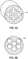
- FIG. 3A illustrates channels 300 having a cross-like cross sectional shape
- FIG. 3B illustrates channels 300 having an hexagonal cross-sectional shape
- FIG. 3C illustrates channels 300 having an octagonal cross-sectional shape
- FIGS. 3D and 3E each illustrate channels 300 having a circular cross-sectional shape
- FIGS. 3F and 3G each illustrate channels 300 having irregularly-shaped cross-sections.
- each of the channels 300 may have a triangular cross-sectional shape, with those channels 300 arranged in the alternating pattern illustrated in FIG. 3H .
- Other cross-sectional shapes are possible as well.
- one or more of the channels may have a different shape and/or size than one or more other channels, as illustrated in, for example, FIG. 3D , wherein all of the channels 300 have a circular shape in cross-section, but some of the channels 300 are larger in diameter than the other channels 300.
- the usage of additive manufacturing techniques to custom manufacture the flame cell allows the one or more channels to be formed so as to define a unique and complex, e.g., a non-linear or curved flow path, rather than the standard, linear flow paths utilized in conventional flame arrestors.
- This is generally accomplished by or via (i) the unique and complex shape of the one or more channels, (ii) rotating the one or more channels about an axis that extends along or is parallel to a centerline of the flame cell, and/or (iii) changing the position of the one or more channels relative to the centerline as the channels extend through the flame cell, such that the one or more channels move away from and/or toward the centerline as the channels extend through the flame cell.
- Various portions of the channels may, in turn, be oriented at different angles relative to the axis.
- a first portion of one of the channels may be oriented at a first angle relative to the axis
- a second portion of that channel may be oriented at a second angle relative to the axis, the second angle being greater than or less than the first angle.
- one or more portions or components of the channels may be oriented substantially perpendicular or exactly perpendicular relative to the axis of the flame cell.
- different channels may be rotated relative to one another and/or converge toward or diverge away from one another.
- FIG. 4A illustrates one example of a flame cell 400 having a unique or complex flow path 404 defined or formed by one or more channels 408 (in this case, one channel 408) having the cross-like cross-sectional shape illustrated in FIG. 3A .
- the channel 408 extends between a first end 412 of the flame cell 400 and a second end 416 of the flame cell 400 opposite the first end 408.
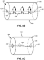
- FIG. 4B illustrates one example of a flame cell 420 having a non-linear or curved flow path 424 formed by rotating one or more channels 428 (in this case, one channel 428) about a central axis 432 of the flame cell 420.
- the channel 428 depicted in FIG. 4B has a circular shape in cross-section. As illustrated, the channel 428 is centered on or about the axis 432 at opposing ends 436 of the flame cell 420, but is rotated (e.g., spiraled, wound) about the axis 432 between the ends 436, such that the non-linear flow path 400 takes on a helical form.
- FIG. 4C illustrates another example of a flame cell 440 having a non-linear or curved flow path 444 formed by rotating one or more channels 448 (in this case, one channel 448) about a central axis 452 of the flame cell 440.
- the channel 448 depicted in FIG. 4C has a cross-like shape in cross-section. As illustrated, the channel 448 is centered on or about the axis 452 at opposing ends 456 of the flame cell 440, but is rotated about the axis 452 between the ends 456.
- FIG. 4D illustrates one example of a flame cell 480 having a non-linear or curved flow path 484 formed by changing the position of one or more channels 488 (in this case, one channel 488) about a central axis 492 of the flame cell 480.
- the channel 488 depicted in FIG. 4D has a substantially rectangular shape in cross-section. As illustrated, the channel 488 is centered on or about the center axis 492 at opposing ends 496 of the flame cell 480, but has two portions 498A that increasingly extend away from the center axis 492 and two portions 498B that increasingly extend toward the center axis 492, such that the flow path 484 zigzags through the flame cell 480.
- the flame cell can include other unique and complex flow paths depending on the given application.
- the unique and complex flow path can partially include a linear or straight portion, with the remaining portion being curved or non-linear.
- the act 204 of creating the customized flame cell optionally includes forming a void in the body of the flame cell, and arranging a sensor within the void.
- the sensor can, for example, be a temperature, photo, infrared, pressure, or other type of sensor.
- the sensor can, in turn, be communicatively connected (either via a wired connection or a wireless connection) to a controller, thereby allowing the controller and/or a user to remotely monitor the flame cell without having to shut down the system employing the flame cell. This allows the controller and/or the user to, for example, remotely monitor or detect the temperature or pressure within the flame cell (e.g., the temperature of the body, the temperature of the flame front), as well as other parameters and data, as desired.
- the temperature or pressure within the flame cell e.g., the temperature of the body, the temperature of the flame front
- the method or process 200 also includes the act 208 of providing a housing for the flame cell.
- the housing generally includes an inlet arranged to be coupled to an upstream component of the pipeline in which the flame arrestor is employed, as well as an outlet arranged to be coupled to a downstream component of the pipeline.
- the housing also includes a chamber or cavity sized to receive the flame cell, as well as additional components for securely retaining the flame cell within the housing.
- the act 208 of providing the housing for the flame cell may involve manufacturing the housing using conventional manufacturing techniques, either before, after, or at the same time as the act 204 is performed. In other cases, however, the act 208 of providing the housing for the flame cell may involve creating the housing using one of the additive manufacturing techniques described above. The housing may be created using a different additive manufacturing technique as the flame cell or using the same additive manufacturing technique as the flame cell. In either situation, the housing may be created before, after, or at the same time as the flame cell is created.
- the method or process 200 further includes the act 212 of securely arranging the created flame cell within the provided housing, thereby forming the flame arrestor.
- the created flame cell may be secured within the housing using threaded bolts or any other known suitable means.
- the flame cell can be secured within the housing by printing the flame cell onto the housing (using additive manufacturing), thereby forming a unitary, one-piece flame arrestor.
- the acts 204, 208, and/or 212 can be performed any number of different times.
- the act 204 can be performed multiple times so as to create multiple (e.g., two, three, four, and so on) flame cells for use in a single housing.
- the flame cells will promote greater levels of turbulent flow than conventional flame arrestors, the flame cells can be arranged within the housing, adjacent one another, without having to dispose screens or expanded metal therebetween, as is the case in some conventional flame arrestors.
- the act 204 can be performed multiple (e.g., two, three, four, and so on) times, with the acts 208 and 212 also performed multiple times, so as to create multiple flame arrestors each having a single flame cell.
- FIG. 5 illustrates an example of a flame cell 500 according to the invention custom manufactured using the method or process 200.
- the flame cell 500 has a substantially cylindrical body 504 and a plurality of channels 508 formed or defined in the body 504.
- Each of the channels 508 has a circular shape in cross-sectional and extends between a first end 512 of the flame cell 500 and a second end 516 of the flame cell 500 opposite the first end 512.
- each of the channels 508 is curved between the first and second ends 512, 516, such that the channels 508 define a curved, or non-linear, flow path.
- the flame cell 500 also includes a void 520 that is formed or defined in the body 504 during manufacturing and is sized to receive a sensor 524 (e.g., a temperature, photo, infrared, pressure, or other type of sensor). While not depicted herein, the sensor 524 can be communicatively connected (either via a wired connection or a wireless connection) to a controller, thereby allowing the controller and/or a user to remotely monitor the flame cell 500 without having to shut down the system employing the flame cell 500.
- a sensor 524 e.g., a temperature, photo, infrared, pressure, or other type of sensor
Landscapes
- Health & Medical Sciences (AREA)
- Public Health (AREA)
- Business, Economics & Management (AREA)
- Emergency Management (AREA)
- Engineering & Computer Science (AREA)
- Chemical & Material Sciences (AREA)
- Materials Engineering (AREA)
- Manufacturing & Machinery (AREA)
- Oil, Petroleum & Natural Gas (AREA)
- Chemical Kinetics & Catalysis (AREA)
- General Chemical & Material Sciences (AREA)
- Mechanical Engineering (AREA)
- General Engineering & Computer Science (AREA)
- Feeding, Discharge, Calcimining, Fusing, And Gas-Generation Devices (AREA)
- Gas Burners (AREA)
- Powder Metallurgy (AREA)
- Thermistors And Varistors (AREA)
- Woven Fabrics (AREA)
- Fuel Cell (AREA)
- Photometry And Measurement Of Optical Pulse Characteristics (AREA)
Description
- The present disclosure generally relates to flame arrestors.
- Flame arrestors can be employed in applications, e.g., chemical, refining, petrochemical, upstream oil and gas, landfill, biogas applications, and the like, involving flammable vapors so as to prevent the flammable vapors from being ignited by potential ignition sources (e.g., flares, flames, exothermic chemical reactions, failed compressor bearings, etc.), which could lead to a fire, a deflagration, and/or a detonation. Flame arrestors, which may, for example, be installed in a pipeline between a fuel source (e.g., one or more storage tanks) and an ignition source (e.g., a flare, a flame), include flow paths that facilitate fluid flow therethrough, but, at the same time, remove heat from a flame front (which may also be referred to as the flame) as it attempts to flow through these flow paths. Flame arrestors thus prevent the flame front from reaching the fuel source, thereby preventing ignition of the fuel source, and, in turn, injuries, environmental issues, and/or damage to equipment and facilities that may result from such an ignition.
- With conventional manufacturing processes, flame arrestors, such as the
flame arrestor 100 of an element assembly shown inFIGS. 1A and1B , include one ormore flame cells 104 that are installed (e.g., welded, captured by welded rings or crossbars) in thehousing 108 and feature a plurality of narrow,linear flame paths 112 that serve to remove heat from a flame front that attempts to flow therethrough, as described above. As best illustrated inFIG. 1B , each of theflame cells 104 employsmultiple layers 116 of crimped metal ribbons that are wound around acore 120 and define or create a plurality of triangularly-shaped openings 124, which in turn define or create thelinear flame paths 112. In some cases, e.g., when theflame arrestor 100 includesmultiple flame cells 104, as is the case inFIGS. 1A and1B (which depicts four flame cells 104), a sheet of expanded metal or ascreen 128 must be installed within thehousing 104 between each pair ofadjacent flame cells 104 so as to create a level of turbulence that ensures adequate heat removal as the flame front travels through theflame arrestor 100. -
US 4 192 657 illustrates an example of a flame arrestor which can be connected with closely adjacent upstream and downstream portions of a pipeline. - In accordance with the invention, a flame cell is provided. The flame cell includes a body and plurality of channels formed in the body. Each of the channels defining non-linear flow path, wherein the body is configured to remove heat from a flame front propagating through the non-linear flow path, a void formed in the body and a sensor arranged within the void to monitor temperature or pressure within the flame cell.
- In accordance with a second exemplary aspect of the present invention, a flame arrestor is provided. The flame arrestor includes a housing, and a flame cell according to the invention arranged in the housing.
- In further accordance with any one or more exemplary aspects, a flame cell and/or a flame arrestor may include any one or more of the following further preferred forms.
- In one preferred form, one or more of the channels are curved.
- In another preferred form, the non-linear flow path has a helical shape.
- In another preferred form, at least one of the channels includes a component oriented substantially perpendicular to a longitudinal axis of the flame cell.
- In another preferred form, each of the channels has a circular cross-sectional shape.
- In another preferred form, each of the channels has an irregular cross-sectional shape.
- In another preferred form, the flame cell includes a body made of a metallic material, the channels being formed in the body.
- In another preferred form, a second flame cell is arranged in the housing, the second flame cell including a second means for inducing turbulence in the flame propagating through the flame arrestor.
- In another preferred form, the flame cell and the second flame cell are not separated by expanded metal.
- In another preferred form, the second means for inducing turbulence includes a second plurality of channels that define a second non-linear flow path different from the non-linear flow path.
- In another preferred form, each of the channels has a circular, rectangular, or irregular cross-sectional shape.
- In another preferred form, the means for inducing turbulence is not a sheet of expanded metal disposed in the flame cell.
- In another preferred form, the act of creating the customized flame cell includes forming a void in the body, and the method further includes arranging a sensor within the void.
- In another preferred form, the act of providing the housing includes creating the housing using the additive manufacturing technique.
- In another preferred form, the method further includes creating an additional customized flame cell using the additive manufacturing technique, and securely arranging the additional flame cell within the housing.
- In another preferred form, the additive manufacturing technique includes 3D printing.
- In another preferred form, the act of forming the one or more channels includes forming one or more curved channels in the body such that the flow path is at least partially non-linear.
- The features of this invention which are believed to be novel are set forth with particularity in the appended claims. The invention may be best understood by reference to the following description taken in conjunction with the accompanying drawings, in which like reference numerals identify like elements in the several FIGS., in which:
-
FIG. 1A is a cross-sectional view of a conventional flame arrestor assembly; -
FIG. 1B is a perspective view of a portion of the conventional flame arrestor assembly ofFIG. 1A ; -
FIG. 2 is a schematic diagram of one example of a process or method according to the teachings of the present disclosure for manufacturing a flame arrestor; -
FIG. 3A is an end view of one example of a flame cell manufactured according to the process ofFIG. 2 and including channels having a cross-like cross-sectional shape; -
FIG. 3B is an end view of one example of a flame cell manufactured according to the process ofFIG. 2 and including channels having a hexagonal cross-sectional shape; -
FIG. 3C is an end view of one example of a flame cell manufactured according to the process ofFIG. 2 and including channels having an octagonal cross-sectional shape; -
FIG. 3D is an end view of one example of a flame cell manufactured according to the process ofFIG. 2 and including channels having a circular cross-sectional shape; -
FIG. 3E is an end view of another example of a flame cell manufactured according to the process ofFIG. 2 and including channels having a circular cross-sectional shape; -
FIG. 3F is an end view of one example of a flame cell manufactured according to the process ofFIG. 2 and including channels having an irregularly-shaped cross-section; -
FIG. 3G is an end view of another example of a flame cell manufactured according to the process ofFIG. 2 and including channels having an irregularly-shaped cross-section; -
FIG. 3H is an end view of one example of a flame cell manufactured according to the process ofFIG. 2 and including channels having a triangular cross-sectional shape and arranged in an alternating pattern; -
FIG. 4A is a perspective view of a flame cell manufactured according to the process ofFIG. 2 and defining a first example of a complex flow path; -
FIG. 4B is a perspective view of a flame cell manufactured according to the process ofFIG. 2 and defining a second example of a complex flow path; -
FIG. 4C is a perspective view of a flame cell manufactured according to the process ofFIG. 2 and defining a third example of a complex flow path; -
FIG. 4D is a perspective view of a flame cell manufactured according to the process ofFIG. 2 and defining a fourth example of a complex flow path; and -
FIG. 5 is a cross-sectional view of a flame cell according to the invention manufactured according to the process ofFIG. 2 and including a plurality of curved channels. - The present disclosure is generally directed to a method of manufacturing a flame arrestor that removes heat from a flame front in a more efficient manner and requires less maintenance than conventionally manufactured flame arrestors such as the
flame arrestor 100. The method described herein utilizes cutting edge manufacturing techniques, like additive manufacturing, to facilitate custom manufacturing of the flame arrestor, as well as various components of the flame arrestor (e.g., one or more flame cells), such that a number of different unique and complex flow paths, e.g., non-linear flow paths, can be developed and incorporated into the resulting flame arrestor in place of the standard, linear flow paths utilized in conventional flame arrestors, depending upon the given application. Unique and complex flow paths promote or induce turbulent flow and encourage nearly continuous (or at least increased) heat transfer from a flame front to the flame arrestor, such that flame arrestors produced according to the method of manufacturing described herein represent an improvement over known flame arrestors. - Beneficially, these unique and complex flow paths also obviate the need for screens or expanded metal, which are sometimes needed in conventional flame arrestors to promote turbulent flow but undesirably result in a large pressure drop across the flame arrestor and may, in some cases, plug the flame cells. In other words, the method described herein can yield a flame arrestor that induces a greater level of turbulent flow than conventional flame arrestors, without producing the negative effects (i.e., a large pressure drop and increased maintenance due to plugging) caused by turbulence inducing screens or expanded metal. In some cases, the method described herein may also reduce the number of flame cells that need to be utilized in a given flame arrestor, such that less material is required, thereby reducing the weight and/or manufacturing cost of the flame arrestor. This also has the potential benefit of facilitating a shorter flame arrestor (as less flame cells are used), which will in turn reduce pressure drops within the flame arrestor.
-
FIG. 2 is a diagram of an example of a method orprocess 200 according to the teachings of the present disclosure. The method orprocess 200 schematically depicted inFIG. 2 is a method or process of custom manufacturing a flame arrestor (also referred to herein as a flame arrestor assembly). Like the conventional flame arrestors described above (e.g., the flame arrestor 100), flame arrestors manufactured according to the method orprocess 200 are configured to remove heat from a flame front, thereby preventing (e.g., extinguishing) a flame from propagating therethrough, but, as described above, does so in a manner that is more efficient and requires less maintenance. - More specifically, the
method 200 includes theact 204 of creating a customized flame cell using an additive manufacturing technique. The additive manufacturing technique may be any additive manufacturing technique or process that builds three-dimensional objects by adding successive layers of material on a material. The additive manufacturing technique may be performed by any suitable machine or combination of machines. The additive manufacturing technique may typically involve or use a computer, three-dimensional modeling software (e.g., Computer Aided Design, or CAD, software), machine equipment, and layering material. Once a CAD model is produced, the machine equipment may read in data from the CAD file and layer or add successive layers of liquid, powder, sheet material (for example) in a layer-upon-layer fashion to fabricate a three-dimensional object. The additive manufacturing technique may include any of several techniques or processes, such as, for example, a stereolithography ("SLA") process, a fused deposition modeling ("FDM") process, multi-jet modeling ("MJM") process, a selective laser sintering ("SLS") process, an electronic beam additive manufacturing process, and an arc welding additive manufacturing process. In some embodiments, the additive manufacturing process may include a directed energy laser deposition process. Such a directed energy laser deposition process may be performed by a multi-axis computer-numerically-controlled ("CNC") lathe with directed energy laser deposition capabilities. - The
act 204 of creating the customized flame cell thus generally includes forming a body and forming one or more channels in the body. The body can be made of one or more suitable materials, such as, for example, stainless steel, aluminum, various alloys (e.g., high nickel alloys), and by virtue of being customizable, can be any number of different shapes and/or sizes. The one or more channels generally define a flow path that is configured to transfer heat from a flame front propagating through the flow path to the body. - The one or more channels, which generally extend between opposing ends of the flame cell, can, by virtue of being customizable, have any number of different sizes and/or shapes in cross-section, and/or be arranged in any number of different patterns or arrays. Generally speaking, each of the one or more channels will have a cross-sectional shape that is not limited to being triangular. As examples,
FIG. 3A illustrateschannels 300 having a cross-like cross sectional shape,FIG. 3B illustrateschannels 300 having an hexagonal cross-sectional shape,FIG. 3C illustrateschannels 300 having an octagonal cross-sectional shape,FIGS. 3D and3E each illustratechannels 300 having a circular cross-sectional shape,FIGS. 3F and3G each illustratechannels 300 having irregularly-shaped cross-sections. Alternatively, each of thechannels 300 may have a triangular cross-sectional shape, with thosechannels 300 arranged in the alternating pattern illustrated inFIG. 3H . Other cross-sectional shapes are possible as well. It will also be appreciated that one or more of the channels may have a different shape and/or size than one or more other channels, as illustrated in, for example,FIG. 3D , wherein all of thechannels 300 have a circular shape in cross-section, but some of thechannels 300 are larger in diameter than theother channels 300. - As discussed above, the usage of additive manufacturing techniques to custom manufacture the flame cell allows the one or more channels to be formed so as to define a unique and complex, e.g., a non-linear or curved flow path, rather than the standard, linear flow paths utilized in conventional flame arrestors. This is generally accomplished by or via (i) the unique and complex shape of the one or more channels, (ii) rotating the one or more channels about an axis that extends along or is parallel to a centerline of the flame cell, and/or (iii) changing the position of the one or more channels relative to the centerline as the channels extend through the flame cell, such that the one or more channels move away from and/or toward the centerline as the channels extend through the flame cell.
- Various portions of the channels may, in turn, be oriented at different angles relative to the axis. As an example, a first portion of one of the channels may be oriented at a first angle relative to the axis, while a second portion of that channel may be oriented at a second angle relative to the axis, the second angle being greater than or less than the first angle. In some cases, one or more portions or components of the channels may be oriented substantially perpendicular or exactly perpendicular relative to the axis of the flame cell. Moreover, while not illustrated herein, different channels may be rotated relative to one another and/or converge toward or diverge away from one another.
-
FIG. 4A illustrates one example of aflame cell 400 having a unique orcomplex flow path 404 defined or formed by one or more channels 408 (in this case, one channel 408) having the cross-like cross-sectional shape illustrated inFIG. 3A . As illustrated, thechannel 408 extends between afirst end 412 of theflame cell 400 and asecond end 416 of theflame cell 400 opposite thefirst end 408. -
FIG. 4B illustrates one example of aflame cell 420 having a non-linear orcurved flow path 424 formed by rotating one or more channels 428 (in this case, one channel 428) about acentral axis 432 of theflame cell 420. Thechannel 428 depicted inFIG. 4B has a circular shape in cross-section. As illustrated, thechannel 428 is centered on or about theaxis 432 at opposing ends 436 of theflame cell 420, but is rotated (e.g., spiraled, wound) about theaxis 432 between theends 436, such that thenon-linear flow path 400 takes on a helical form. -
FIG. 4C illustrates another example of aflame cell 440 having a non-linear orcurved flow path 444 formed by rotating one or more channels 448 (in this case, one channel 448) about acentral axis 452 of theflame cell 440. Thechannel 448 depicted inFIG. 4C has a cross-like shape in cross-section. As illustrated, thechannel 448 is centered on or about theaxis 452 at opposing ends 456 of theflame cell 440, but is rotated about theaxis 452 between the ends 456. -
FIG. 4D illustrates one example of aflame cell 480 having a non-linear orcurved flow path 484 formed by changing the position of one or more channels 488 (in this case, one channel 488) about acentral axis 492 of theflame cell 480. Thechannel 488 depicted inFIG. 4D has a substantially rectangular shape in cross-section. As illustrated, thechannel 488 is centered on or about thecenter axis 492 at opposing ends 496 of theflame cell 480, but has twoportions 498A that increasingly extend away from thecenter axis 492 and twoportions 498B that increasingly extend toward thecenter axis 492, such that theflow path 484 zigzags through theflame cell 480. - It will be appreciated that the flame cell can include other unique and complex flow paths depending on the given application. In some cases, the unique and complex flow path can partially include a linear or straight portion, with the remaining portion being curved or non-linear.
- In some cases, the
act 204 of creating the customized flame cell optionally includes forming a void in the body of the flame cell, and arranging a sensor within the void. The sensor can, for example, be a temperature, photo, infrared, pressure, or other type of sensor. The sensor can, in turn, be communicatively connected (either via a wired connection or a wireless connection) to a controller, thereby allowing the controller and/or a user to remotely monitor the flame cell without having to shut down the system employing the flame cell. This allows the controller and/or the user to, for example, remotely monitor or detect the temperature or pressure within the flame cell (e.g., the temperature of the body, the temperature of the flame front), as well as other parameters and data, as desired. - The method or
process 200 also includes theact 208 of providing a housing for the flame cell. The housing generally includes an inlet arranged to be coupled to an upstream component of the pipeline in which the flame arrestor is employed, as well as an outlet arranged to be coupled to a downstream component of the pipeline. The housing also includes a chamber or cavity sized to receive the flame cell, as well as additional components for securely retaining the flame cell within the housing. - In some cases, the
act 208 of providing the housing for the flame cell may involve manufacturing the housing using conventional manufacturing techniques, either before, after, or at the same time as theact 204 is performed. In other cases, however, theact 208 of providing the housing for the flame cell may involve creating the housing using one of the additive manufacturing techniques described above. The housing may be created using a different additive manufacturing technique as the flame cell or using the same additive manufacturing technique as the flame cell. In either situation, the housing may be created before, after, or at the same time as the flame cell is created. - The method or
process 200 further includes theact 212 of securely arranging the created flame cell within the provided housing, thereby forming the flame arrestor. In some cases, e.g., when the housing is manufactured using conventional techniques, the created flame cell may be secured within the housing using threaded bolts or any other known suitable means. In other cases, e.g., when the housing is manufactured using the same additive manufacturing technique used to manufacture the flame cell, the flame cell can be secured within the housing by printing the flame cell onto the housing (using additive manufacturing), thereby forming a unitary, one-piece flame arrestor. - It will be appreciated that the
acts act 204 can be performed multiple times so as to create multiple (e.g., two, three, four, and so on) flame cells for use in a single housing. Beneficially, because the flame cells will promote greater levels of turbulent flow than conventional flame arrestors, the flame cells can be arranged within the housing, adjacent one another, without having to dispose screens or expanded metal therebetween, as is the case in some conventional flame arrestors. In other cases, theact 204 can be performed multiple (e.g., two, three, four, and so on) times, with theacts -
FIG. 5 illustrates an example of a flame cell 500 according to the invention custom manufactured using the method orprocess 200. The flame cell 500 has a substantiallycylindrical body 504 and a plurality ofchannels 508 formed or defined in thebody 504. Each of thechannels 508 has a circular shape in cross-sectional and extends between afirst end 512 of the flame cell 500 and asecond end 516 of the flame cell 500 opposite thefirst end 512. As illustrated, each of thechannels 508 is curved between the first and second ends 512, 516, such that thechannels 508 define a curved, or non-linear, flow path. As discussed above, this curved, or non-linear, flow path advantageously promotes or induces turbulent flow so as to ensure adequate heat transfer from the flame front to the flame cell 500 as fluid flows through the flame cell 500. The flame cell 500 also includes a void 520 that is formed or defined in thebody 504 during manufacturing and is sized to receive a sensor 524 (e.g., a temperature, photo, infrared, pressure, or other type of sensor). While not depicted herein, thesensor 524 can be communicatively connected (either via a wired connection or a wireless connection) to a controller, thereby allowing the controller and/or a user to remotely monitor the flame cell 500 without having to shut down the system employing the flame cell 500. - Preferred embodiments of this invention are described herein, including the best mode or modes known to the inventors for carrying out the invention. Although numerous examples are shown and described herein, those of skill in the art will readily understand that details of the various embodiments need not be mutually exclusive. Instead, those of skill in the art upon reading the teachings herein should be able to combine one or more features of one embodiment with one or more features of the remaining embodiments. Further, it also should be understood that the illustrated embodiments are exemplary only, and should not be taken as limiting the scope of the invention. All methods described herein can be performed in any suitable order unless otherwise indicated herein or otherwise clearly contradicted by context. The use of any and all examples, or exemplary language (e.g., "such as") provided herein, is intended merely to better illuminate the aspects of the exemplary embodiment or embodiments of the invention, and do not pose a limitation on the scope of the invention. No language in the specification should be construed as indicating any non-claimed element as essential to the practice of the invention.
Claims (13)
- A flame cell (400; 420; 440; 480; 500), comprising:a body (504);a plurality of channels (300; 408; 428; 448; 488; 508) formed in the body, each of the channels defining a non-linear flow path, wherein the body is configured to remove heat from a flame front propagating through the non-linear flow path;a void (520) formed in the body (504) anda sensor (524) arranged within the void to monitor temperature or pressure within the flame cell.
- The flame cell (400; 420; 440; 480; 500) of claim 1, wherein each of the channels (300; 408; 428; 448; 488; 508) are curved.
- The flame cell (400; 420; 440; 480; 500) of any preceding claim,
wherein the non-linear flow path has a helical shape. - The flame cell (400; 420; 440; 480; 500) of any preceding claim,
wherein at least one of the channels (300; 408; 428; 448; 488; 508) comprises a component oriented substantially perpendicular to a longitudinal axis of the flame cell. - The flame cell (400; 420; 440; 480; 500) of any preceding claim,
wherein each of the channels (300; 428; 508) has a circular cross-sectional shape. - The flame cell (400; 420; 440; 480; 500) of any preceding claim,
wherein each of the channels (300) has an irregular cross-sectional shape. - A flame arrestor, comprising:a housing; andthe flame cell (400; 420; 440; 480; 500) according to any of the preceding claims, the flame cell being arranged in the housing.
- The flame arrestor of claim 7, the body (504) is made of a metallic material.
- The flame arrestor of claim 7 or 8, further comprising a second flame cell (400; 420; 440; 480; 500) arranged in the housing, the second flame cell comprising a second means for inducing turbulence in the flame propagating through the flame arrestor.
- The flame arrestor of claim 9, wherein the flame cell (400; 420; 440; 480; 500) and the second flame cell (400; 420; 440; 480; 500) are not separated by expanded metal.
- The flame arrestor of claim 9 or 10, wherein the second means for inducing turbulence comprises a second plurality of channels (300; 408; 428; 448; 488; 508) that define a second non-linear flow path different from the non-linear flow path.
- The flame arrestor of any of the claims 7-11, wherein each of the channels (300; 408; 428; 448; 488; 508) has a circular, rectangular, or irregular cross-sectional shape.
- The flame arrestor of any one of claims 9-12, wherein the second means for inducing turbulence is not a sheet of expanded metal disposed in the flame cell (400; 420; 440; 480; 500).
Priority Applications (1)
| Application Number | Priority Date | Filing Date | Title |
|---|---|---|---|
| EP22193299.9A EP4119199A1 (en) | 2016-08-31 | 2017-08-24 | Method for manufacturing a flame arrestor |
Applications Claiming Priority (2)
| Application Number | Priority Date | Filing Date | Title |
|---|---|---|---|
| US15/253,437 US20180056100A1 (en) | 2016-08-31 | 2016-08-31 | Method for Manufacturing a Flame Arrestor |
| PCT/US2017/048356 WO2018044671A1 (en) | 2016-08-31 | 2017-08-24 | Method for manufacturing a flame arrestor |
Related Child Applications (2)
| Application Number | Title | Priority Date | Filing Date |
|---|---|---|---|
| EP22193299.9A Division-Into EP4119199A1 (en) | 2016-08-31 | 2017-08-24 | Method for manufacturing a flame arrestor |
| EP22193299.9A Division EP4119199A1 (en) | 2016-08-31 | 2017-08-24 | Method for manufacturing a flame arrestor |
Publications (2)
| Publication Number | Publication Date |
|---|---|
| EP3506987A1 EP3506987A1 (en) | 2019-07-10 |
| EP3506987B1 true EP3506987B1 (en) | 2022-11-16 |
Family
ID=59895361
Family Applications (2)
| Application Number | Title | Priority Date | Filing Date |
|---|---|---|---|
| EP17768540.1A Active EP3506987B1 (en) | 2016-08-31 | 2017-08-24 | Flame cell and a flame arrestor comprising the flame cell |
| EP22193299.9A Pending EP4119199A1 (en) | 2016-08-31 | 2017-08-24 | Method for manufacturing a flame arrestor |
Family Applications After (1)
| Application Number | Title | Priority Date | Filing Date |
|---|---|---|---|
| EP22193299.9A Pending EP4119199A1 (en) | 2016-08-31 | 2017-08-24 | Method for manufacturing a flame arrestor |
Country Status (8)
| Country | Link |
|---|---|
| US (2) | US20180056100A1 (en) |
| EP (2) | EP3506987B1 (en) |
| KR (1) | KR20190042060A (en) |
| CN (2) | CN208611632U (en) |
| BR (1) | BR112019004089A2 (en) |
| MX (2) | MX2019002394A (en) |
| RU (1) | RU2757192C2 (en) |
| WO (1) | WO2018044671A1 (en) |
Families Citing this family (17)
| Publication number | Priority date | Publication date | Assignee | Title |
|---|---|---|---|---|
| US11227749B2 (en) * | 2016-02-18 | 2022-01-18 | Lam Research Corporation | 3D printed plasma arrestor for an electrostatic chuck |
| US9987508B2 (en) | 2016-08-31 | 2018-06-05 | Emerson Process Management Regulator Technologies Tulsa, Llc | Hybrid composite flame cell |
| US20180056100A1 (en) | 2016-08-31 | 2018-03-01 | Emerson Process Management Regulator Technologies Tulsa, Llc | Method for Manufacturing a Flame Arrestor |
| US11168883B2 (en) * | 2017-09-29 | 2021-11-09 | Rosemount Aerospace Inc. | Flame arrestor with fluid drainage capabilities |
| US11232874B2 (en) * | 2017-12-18 | 2022-01-25 | Ge-Hitachi Nuclear Energy Americas Llc | Multiple-path flow restrictor nozzle |
| US10463896B2 (en) * | 2018-03-09 | 2019-11-05 | Jamco Products, Inc. | Flame arrestor and safety cabinet equipped therewith |
| CN109157780B (en) * | 2018-07-18 | 2019-10-01 | 江苏大学 | A kind of buffering wall-flow type multi-pore channel fire arrester |
| US10967580B2 (en) | 2018-09-18 | 2021-04-06 | General Electric Company | Support structures for additively-manufactured components and methods of securing a component to a build platform during additive manufacturing |
| IT201800010006A1 (en) * | 2018-11-02 | 2020-05-02 | Sumitomo Riko Co Ltd | INTERNAL HEAT EXCHANGER |
| CN110298091B (en) * | 2019-06-18 | 2020-11-13 | 四川大学 | Corrugated flame arrester pore channel structure design method based on cut-distance integration |
| CN110575635A (en) * | 2019-09-17 | 2019-12-17 | 郝立顺 | Use 3D to print spark arrester of curved through-hole fire blocking plate |
| CN113813531B (en) * | 2020-06-18 | 2023-08-01 | 中国石油化工股份有限公司 | High-pressure-bearing flame arrester with composite flame-retardant structure |
| US11992721B2 (en) | 2020-07-08 | 2024-05-28 | Rosemount Inc. | Flame arrester for process devices |
| US12013116B2 (en) | 2021-02-26 | 2024-06-18 | Emerson Process Management Regulator Tech Inc. | Flame arrestors and methods of making flame arrestors |
| WO2023147373A1 (en) * | 2022-01-26 | 2023-08-03 | Scepter U.S. Holding Company | Flame mitigation device for fuel container |
| KR102769333B1 (en) * | 2022-10-31 | 2025-02-18 | 주식회사 스카이엔텍 | Flange Cover for Back Fire Prevention |
| DE102023101925A1 (en) | 2023-01-26 | 2024-08-01 | Man Energy Solutions Se | Tube bundle reactor |
Family Cites Families (68)
| Publication number | Priority date | Publication date | Assignee | Title |
|---|---|---|---|---|
| US290559A (en) * | 1883-12-18 | Safety oil-tank | ||
| US258749A (en) * | 1882-05-30 | Protector for oil-tanks | ||
| US3356255A (en) * | 1967-12-05 | Breather and drain | ||
| US802380A (en) * | 1904-12-30 | 1905-10-24 | George H Emerson | Safety device for gas systems. |
| US840992A (en) * | 1906-04-13 | 1907-01-08 | Jacob Cohn | Safety venting attachment for receptacles. |
| US875481A (en) * | 1907-02-20 | 1907-12-31 | Lyman A Wilson | Safety-closure for receptacles. |
| US958944A (en) * | 1909-09-13 | 1910-05-24 | Alden A Steward | Fire-check. |
| US1011988A (en) * | 1911-07-21 | 1911-12-19 | Carey Philip Mfg Co | Gas-tank absorbent filler. |
| US1134838A (en) * | 1914-04-30 | 1915-04-06 | Victor Gaumer | Safety device for inflammable-material containers. |
| US1259029A (en) * | 1917-07-28 | 1918-03-12 | Gas And Oil Comb Company | Apparatus for burning explosive gaseous mixtures. |
| US1701805A (en) * | 1927-02-11 | 1929-02-12 | Irwin L Dunn | Explosion arrester |
| US1755624A (en) * | 1928-06-14 | 1930-04-22 | Miles F Yount | Flame arrester |
| US2087170A (en) * | 1930-09-12 | 1937-07-13 | Stephenson Arthur | Device for the prevention of backfires in gas apparatus |
| US2388395A (en) * | 1942-11-20 | 1945-11-06 | James J Duggan | Combined flame arrester and vent valve |
| US2376933A (en) * | 1943-01-04 | 1945-05-29 | Stone Wheel Inc | Spark and flame arrestor |
| US2420599A (en) * | 1944-02-04 | 1947-05-13 | Shand And Jurs Company | Flame arrester |
| DE1125847B (en) | 1961-07-27 | 1962-03-15 | Leinemann Co Flammenfilter | Respiratory organ with flame protection grate and protective hood that dissolves automatically when exposed to heat for containers for storage and transport of flammable liquids and gases |
| US3287094A (en) * | 1963-09-30 | 1966-11-22 | Fisher Ind | Flame arrester |
| US3490644A (en) * | 1966-11-07 | 1970-01-20 | Max E Redburn | Fume arrester |
| GB1290861A (en) * | 1969-03-19 | 1972-09-27 | ||
| US3650431A (en) * | 1969-12-19 | 1972-03-21 | Phillips Petroleum Co | Safety container |
| AT311129B (en) * | 1970-02-13 | 1973-10-25 | Hoerbiger Ventilwerke Ag | Explosion relief valve |
| DE2128535C2 (en) | 1970-08-06 | 1984-01-05 | Carlo Settimo Milanese Milano Chiti | Fireproof fuel container for land and water vehicles |
| US4015954A (en) * | 1975-12-29 | 1977-04-05 | John Zink Company | Laminar flow flame arrestor |
| US4192657A (en) * | 1978-07-03 | 1980-03-11 | Atlantic Richfield Company | Method and apparatus for halting the advancement of ethylene decomposition flame fronts |
| AU531644B2 (en) * | 1979-09-07 | 1983-09-01 | Explosafe S.A. | Traversable pathway through flammable fluid |
| US4387829A (en) * | 1982-01-06 | 1983-06-14 | Cooper Industries, Inc. | Combination breather-drain |
| SU1260007A1 (en) * | 1984-05-29 | 1986-09-30 | Elnatanov Aleksandr | Fire barrier |
| US5211554A (en) | 1990-12-20 | 1993-05-18 | Rajewski Robert K | Detonation arrestor with stacked plates |
| CA2032791C (en) | 1990-12-20 | 1994-08-30 | Tornado Flare Systems (Canada) Inc. | Detonation arrestor |
| US5246130A (en) * | 1991-06-21 | 1993-09-21 | General Motors Corporation | Fuel storage apparatus |
| SG49198A1 (en) * | 1992-06-30 | 1998-05-18 | Chem Mech Engineering | Flame arrestor apparatus |
| DE10112957B4 (en) * | 2001-03-17 | 2005-12-22 | Leinemann Gmbh & Co. | Flame arrester arrangement |
| US20030165638A1 (en) * | 2001-07-06 | 2003-09-04 | Louks John W. | Inorganic fiber substrates for exhaust systems and methods of making same |
| US6612830B2 (en) | 2001-08-10 | 2003-09-02 | Precision Combustion, Inc. | Anode gas burner for inert gas generation, method and apparatus |
| US6699035B2 (en) | 2001-09-06 | 2004-03-02 | Enardo, Inc. | Detonation flame arrestor including a spiral wound wedge wire screen for gases having a low MESG |
| DE10326150B4 (en) | 2003-06-06 | 2005-12-15 | Leinemann Gmbh & Co. Kg | Durable fire barrier |
| CN1244383C (en) | 2003-07-20 | 2006-03-08 | 大连理工大学 | Multi-layer slit heat pipe fire suppressor |
| DE10336530B3 (en) * | 2003-08-05 | 2005-02-17 | Leinemann Gmbh & Co. | Flame arrester |
| JP5015766B2 (en) | 2005-02-04 | 2012-08-29 | 日本碍子株式会社 | Permselective membrane reactor |
| GB0508096D0 (en) * | 2005-04-21 | 2005-06-01 | Knitmesh Ltd | Detonation flame arrestor |
| DE102006026779A1 (en) * | 2006-06-07 | 2007-12-20 | Leinemann Gmbh & Co. Kg | Flame arrestor arrangement and method for introducing bores into a flame arrester arrangement |
| CN100398416C (en) | 2006-06-13 | 2008-07-02 | 黄晓东 | Safe and environment-friendly buried oil storage tank |
| US20080271814A1 (en) * | 2007-05-04 | 2008-11-06 | Gm Global Technology Operations, Inc. | Honeycomb Flame Arrester and Flow Straightener for a Fuel System Fuel Fill Pipe |
| TWI390145B (en) * | 2008-03-31 | 2013-03-21 | Rohm & Haas | Method and apparatus for deflagration pressure attenuation |
| US20090321045A1 (en) | 2008-06-30 | 2009-12-31 | Alcatel-Lucent Technologies Inc. | Monolithic structurally complex heat sink designs |
| US8512430B2 (en) * | 2009-05-05 | 2013-08-20 | Cooper Technologies Company | Explosion-proof enclosures with active thermal management using sintered elements |
| US8828311B2 (en) | 2009-05-15 | 2014-09-09 | Board Of Regents, The University Of Texas System | Reticulated mesh arrays and dissimilar array monoliths by additive layered manufacturing using electron and laser beam melting |
| EP2260937A1 (en) | 2009-06-12 | 2010-12-15 | DSM IP Assets B.V. | Device for processing and conditioning of material transported through the device |
| US8573289B1 (en) | 2009-07-20 | 2013-11-05 | Hrl Laboratories, Llc | Micro-architected materials for heat exchanger applications |
| DE102010016782B4 (en) * | 2010-05-04 | 2016-12-08 | R.Stahl Schaltgeräte GmbH | Pressure relief device for flameproof enclosures |
| GB201107087D0 (en) * | 2011-04-28 | 2011-06-08 | Airbus Operations Ltd | A flame trap cartridge, flame arrestor, method of preventing flame propagation into a fuel tank and method of operating an aircraft |
| US9151415B2 (en) | 2012-07-17 | 2015-10-06 | Chevron U.S.A. Inc. | Method and apparatus for reducing fluid flow friction in a pipe |
| CN202822545U (en) * | 2012-08-02 | 2013-03-27 | 启东市精博化工设备厂 | Flame damper |
| DE102012111757B4 (en) | 2012-12-04 | 2022-05-19 | Sartorius Stedim Biotech Gmbh | Device for flow measurement in hose and/or plastic pipe systems |
| WO2014105108A1 (en) | 2012-12-28 | 2014-07-03 | United Technologies Corporation | Gas turbine engine component having vascular engineered lattice structure |
| DE102013210094A1 (en) | 2013-04-12 | 2014-10-16 | Behr Gmbh & Co. Kg | Wärmeübertragerbauteil |
| DE102014116149A1 (en) * | 2014-11-06 | 2016-05-12 | R. Stahl Schaltgeräte GmbH | Flame-proofing filter of a number of layer sequences as well as arrangements of flameproof filters and their use |
| US20160136467A1 (en) * | 2014-11-18 | 2016-05-19 | Air Liquide Large Industries U.S. Lp | Detonation arrestor for cavern storage |
| US11154737B2 (en) * | 2014-12-05 | 2021-10-26 | M.A. Industries, Inc. | Flame retardant porous plastic resins |
| CN104623832A (en) * | 2015-02-02 | 2015-05-20 | 北京矿大节能科技有限公司 | Ceramic core flame arrester |
| US10890325B2 (en) * | 2015-04-17 | 2021-01-12 | Eaton Intelligent Power Limited | Flame arrestor |
| US10512805B2 (en) * | 2015-07-21 | 2019-12-24 | The Boeing Company | Ignition-quenching systems, apparatuses, and methods |
| US10221694B2 (en) | 2016-02-17 | 2019-03-05 | United Technologies Corporation | Gas turbine engine component having vascular engineered lattice structure |
| US9987508B2 (en) * | 2016-08-31 | 2018-06-05 | Emerson Process Management Regulator Technologies Tulsa, Llc | Hybrid composite flame cell |
| US20180056100A1 (en) | 2016-08-31 | 2018-03-01 | Emerson Process Management Regulator Technologies Tulsa, Llc | Method for Manufacturing a Flame Arrestor |
| CA3037301C (en) * | 2016-09-16 | 2023-08-08 | Cv Technology, Inc. | System, apparatus, & method for flame arrester |
| US10704841B2 (en) | 2017-01-03 | 2020-07-07 | Titan Tensor LLC | Monolithic bicontinuous labyrinth structures and methods for their manufacture |
-
2016
- 2016-08-31 US US15/253,437 patent/US20180056100A1/en not_active Abandoned
-
2017
- 2017-08-24 BR BR112019004089A patent/BR112019004089A2/en not_active IP Right Cessation
- 2017-08-24 MX MX2019002394A patent/MX2019002394A/en unknown
- 2017-08-24 KR KR1020197008416A patent/KR20190042060A/en not_active Ceased
- 2017-08-24 RU RU2019106369A patent/RU2757192C2/en active
- 2017-08-24 WO PCT/US2017/048356 patent/WO2018044671A1/en not_active Ceased
- 2017-08-24 EP EP17768540.1A patent/EP3506987B1/en active Active
- 2017-08-24 EP EP22193299.9A patent/EP4119199A1/en active Pending
- 2017-08-31 CN CN201721111722.XU patent/CN208611632U/en active Active
- 2017-08-31 CN CN201710769676.0A patent/CN107789763A/en active Pending
-
2019
- 2019-02-27 MX MX2024000784A patent/MX2024000784A/en unknown
-
2020
- 2020-01-08 US US16/737,741 patent/US11596820B2/en active Active
Also Published As
| Publication number | Publication date |
|---|---|
| RU2757192C2 (en) | 2021-10-11 |
| CN208611632U (en) | 2019-03-19 |
| CN107789763A (en) | 2018-03-13 |
| US11596820B2 (en) | 2023-03-07 |
| US20180056100A1 (en) | 2018-03-01 |
| CA3033907A1 (en) | 2018-03-08 |
| MX2024000784A (en) | 2024-02-06 |
| EP4119199A1 (en) | 2023-01-18 |
| KR20190042060A (en) | 2019-04-23 |
| RU2019106369A (en) | 2020-10-01 |
| US20200139173A1 (en) | 2020-05-07 |
| BR112019004089A2 (en) | 2019-05-28 |
| RU2019106369A3 (en) | 2020-12-08 |
| WO2018044671A1 (en) | 2018-03-08 |
| EP3506987A1 (en) | 2019-07-10 |
| MX2019002394A (en) | 2019-07-08 |
Similar Documents
| Publication | Publication Date | Title |
|---|---|---|
| US11596820B2 (en) | Method for manufacturing a flame arrestor | |
| US11167158B2 (en) | Hybrid composite flame cell | |
| Min et al. | Experimental investigation on additively manufactured transpiration and film cooling structures | |
| Alshare et al. | Hydraulic manifold design via additive manufacturing optimized with CFD and fluid-structure interaction simulations | |
| Alya et al. | Discrete phase modeling of the powder flow dynamics and the catchment efficiency in laser directed energy deposition with inclined coaxial nozzles | |
| JP2021105213A (en) | Methods and multi-purpose powder removal features for additive manufacturing | |
| CN109414922A (en) | Method and thin-walled enhancing structure for increasing material manufacturing | |
| WO2014189501A1 (en) | Submerged combustion burners, melters, and methods of use | |
| Meisel et al. | Redesigning a reaction control thruster for metal-based additive manufacturing: a case study in design for additive manufacturing | |
| US20180340630A1 (en) | Method of Manufacturing a Fluid Pressure Reduction Device | |
| CN213512098U (en) | Fluid flow control devices and valve trims for fluid flow control devices | |
| CA3033907C (en) | Method for manufacturing a flame arrestor | |
| Marshall et al. | Design of an additively manufactured recuperator with 800° C inlet temperature for sCO2 power cycle application | |
| CN216319631U (en) | Flame arrestor for process equipment and combustion analyzer | |
| Yanchevskyi et al. | Circular packing for support-free structures. | |
| CA3232157A1 (en) | Stochastic structures | |
| Caravella et al. | Optimization of temperature distribution in the novel power-to-heat matrix-in-batch OnePot© reactor | |
| Tang | Reaction-diffusion fronts in heterogeneous combustion |
Legal Events
| Date | Code | Title | Description |
|---|---|---|---|
| STAA | Information on the status of an ep patent application or granted ep patent |
Free format text: STATUS: UNKNOWN |
|
| STAA | Information on the status of an ep patent application or granted ep patent |
Free format text: STATUS: THE INTERNATIONAL PUBLICATION HAS BEEN MADE |
|
| PUAI | Public reference made under article 153(3) epc to a published international application that has entered the european phase |
Free format text: ORIGINAL CODE: 0009012 |
|
| STAA | Information on the status of an ep patent application or granted ep patent |
Free format text: STATUS: REQUEST FOR EXAMINATION WAS MADE |
|
| 17P | Request for examination filed |
Effective date: 20190208 |
|
| AK | Designated contracting states |
Kind code of ref document: A1 Designated state(s): AL AT BE BG CH CY CZ DE DK EE ES FI FR GB GR HR HU IE IS IT LI LT LU LV MC MK MT NL NO PL PT RO RS SE SI SK SM TR |
|
| AX | Request for extension of the european patent |
Extension state: BA ME |
|
| DAV | Request for validation of the european patent (deleted) | ||
| DAX | Request for extension of the european patent (deleted) | ||
| GRAP | Despatch of communication of intention to grant a patent |
Free format text: ORIGINAL CODE: EPIDOSNIGR1 |
|
| STAA | Information on the status of an ep patent application or granted ep patent |
Free format text: STATUS: GRANT OF PATENT IS INTENDED |
|
| INTG | Intention to grant announced |
Effective date: 20220622 |
|
| GRAS | Grant fee paid |
Free format text: ORIGINAL CODE: EPIDOSNIGR3 |
|
| GRAA | (expected) grant |
Free format text: ORIGINAL CODE: 0009210 |
|
| STAA | Information on the status of an ep patent application or granted ep patent |
Free format text: STATUS: THE PATENT HAS BEEN GRANTED |
|
| AK | Designated contracting states |
Kind code of ref document: B1 Designated state(s): AL AT BE BG CH CY CZ DE DK EE ES FI FR GB GR HR HU IE IS IT LI LT LU LV MC MK MT NL NO PL PT RO RS SE SI SK SM TR |
|
| REG | Reference to a national code |
Ref country code: GB Ref legal event code: FG4D |
|
| REG | Reference to a national code |
Ref country code: CH Ref legal event code: EP |
|
| REG | Reference to a national code |
Ref country code: IE Ref legal event code: FG4D |
|
| REG | Reference to a national code |
Ref country code: DE Ref legal event code: R096 Ref document number: 602017063759 Country of ref document: DE |
|
| REG | Reference to a national code |
Ref country code: AT Ref legal event code: REF Ref document number: 1531417 Country of ref document: AT Kind code of ref document: T Effective date: 20221215 |
|
| REG | Reference to a national code |
Ref country code: LT Ref legal event code: MG9D |
|
| REG | Reference to a national code |
Ref country code: NL Ref legal event code: MP Effective date: 20221116 |
|
| REG | Reference to a national code |
Ref country code: AT Ref legal event code: MK05 Ref document number: 1531417 Country of ref document: AT Kind code of ref document: T Effective date: 20221116 |
|
| PG25 | Lapsed in a contracting state [announced via postgrant information from national office to epo] |
Ref country code: SE Free format text: LAPSE BECAUSE OF FAILURE TO SUBMIT A TRANSLATION OF THE DESCRIPTION OR TO PAY THE FEE WITHIN THE PRESCRIBED TIME-LIMIT Effective date: 20221116 Ref country code: PT Free format text: LAPSE BECAUSE OF FAILURE TO SUBMIT A TRANSLATION OF THE DESCRIPTION OR TO PAY THE FEE WITHIN THE PRESCRIBED TIME-LIMIT Effective date: 20230316 Ref country code: NO Free format text: LAPSE BECAUSE OF FAILURE TO SUBMIT A TRANSLATION OF THE DESCRIPTION OR TO PAY THE FEE WITHIN THE PRESCRIBED TIME-LIMIT Effective date: 20230216 Ref country code: LT Free format text: LAPSE BECAUSE OF FAILURE TO SUBMIT A TRANSLATION OF THE DESCRIPTION OR TO PAY THE FEE WITHIN THE PRESCRIBED TIME-LIMIT Effective date: 20221116 Ref country code: FI Free format text: LAPSE BECAUSE OF FAILURE TO SUBMIT A TRANSLATION OF THE DESCRIPTION OR TO PAY THE FEE WITHIN THE PRESCRIBED TIME-LIMIT Effective date: 20221116 Ref country code: ES Free format text: LAPSE BECAUSE OF FAILURE TO SUBMIT A TRANSLATION OF THE DESCRIPTION OR TO PAY THE FEE WITHIN THE PRESCRIBED TIME-LIMIT Effective date: 20221116 Ref country code: AT Free format text: LAPSE BECAUSE OF FAILURE TO SUBMIT A TRANSLATION OF THE DESCRIPTION OR TO PAY THE FEE WITHIN THE PRESCRIBED TIME-LIMIT Effective date: 20221116 |
|
| PG25 | Lapsed in a contracting state [announced via postgrant information from national office to epo] |
Ref country code: RS Free format text: LAPSE BECAUSE OF FAILURE TO SUBMIT A TRANSLATION OF THE DESCRIPTION OR TO PAY THE FEE WITHIN THE PRESCRIBED TIME-LIMIT Effective date: 20221116 Ref country code: PL Free format text: LAPSE BECAUSE OF FAILURE TO SUBMIT A TRANSLATION OF THE DESCRIPTION OR TO PAY THE FEE WITHIN THE PRESCRIBED TIME-LIMIT Effective date: 20221116 Ref country code: LV Free format text: LAPSE BECAUSE OF FAILURE TO SUBMIT A TRANSLATION OF THE DESCRIPTION OR TO PAY THE FEE WITHIN THE PRESCRIBED TIME-LIMIT Effective date: 20221116 Ref country code: IS Free format text: LAPSE BECAUSE OF FAILURE TO SUBMIT A TRANSLATION OF THE DESCRIPTION OR TO PAY THE FEE WITHIN THE PRESCRIBED TIME-LIMIT Effective date: 20230316 Ref country code: HR Free format text: LAPSE BECAUSE OF FAILURE TO SUBMIT A TRANSLATION OF THE DESCRIPTION OR TO PAY THE FEE WITHIN THE PRESCRIBED TIME-LIMIT Effective date: 20221116 Ref country code: GR Free format text: LAPSE BECAUSE OF FAILURE TO SUBMIT A TRANSLATION OF THE DESCRIPTION OR TO PAY THE FEE WITHIN THE PRESCRIBED TIME-LIMIT Effective date: 20230217 |
|
| PG25 | Lapsed in a contracting state [announced via postgrant information from national office to epo] |
Ref country code: NL Free format text: LAPSE BECAUSE OF FAILURE TO SUBMIT A TRANSLATION OF THE DESCRIPTION OR TO PAY THE FEE WITHIN THE PRESCRIBED TIME-LIMIT Effective date: 20221116 |
|
| P01 | Opt-out of the competence of the unified patent court (upc) registered |
Effective date: 20230525 |
|
| PG25 | Lapsed in a contracting state [announced via postgrant information from national office to epo] |
Ref country code: SM Free format text: LAPSE BECAUSE OF FAILURE TO SUBMIT A TRANSLATION OF THE DESCRIPTION OR TO PAY THE FEE WITHIN THE PRESCRIBED TIME-LIMIT Effective date: 20221116 Ref country code: RO Free format text: LAPSE BECAUSE OF FAILURE TO SUBMIT A TRANSLATION OF THE DESCRIPTION OR TO PAY THE FEE WITHIN THE PRESCRIBED TIME-LIMIT Effective date: 20221116 Ref country code: EE Free format text: LAPSE BECAUSE OF FAILURE TO SUBMIT A TRANSLATION OF THE DESCRIPTION OR TO PAY THE FEE WITHIN THE PRESCRIBED TIME-LIMIT Effective date: 20221116 Ref country code: DK Free format text: LAPSE BECAUSE OF FAILURE TO SUBMIT A TRANSLATION OF THE DESCRIPTION OR TO PAY THE FEE WITHIN THE PRESCRIBED TIME-LIMIT Effective date: 20221116 Ref country code: CZ Free format text: LAPSE BECAUSE OF FAILURE TO SUBMIT A TRANSLATION OF THE DESCRIPTION OR TO PAY THE FEE WITHIN THE PRESCRIBED TIME-LIMIT Effective date: 20221116 |
|
| REG | Reference to a national code |
Ref country code: DE Ref legal event code: R097 Ref document number: 602017063759 Country of ref document: DE |
|
| PG25 | Lapsed in a contracting state [announced via postgrant information from national office to epo] |
Ref country code: SK Free format text: LAPSE BECAUSE OF FAILURE TO SUBMIT A TRANSLATION OF THE DESCRIPTION OR TO PAY THE FEE WITHIN THE PRESCRIBED TIME-LIMIT Effective date: 20221116 Ref country code: AL Free format text: LAPSE BECAUSE OF FAILURE TO SUBMIT A TRANSLATION OF THE DESCRIPTION OR TO PAY THE FEE WITHIN THE PRESCRIBED TIME-LIMIT Effective date: 20221116 |
|
| PLBE | No opposition filed within time limit |
Free format text: ORIGINAL CODE: 0009261 |
|
| STAA | Information on the status of an ep patent application or granted ep patent |
Free format text: STATUS: NO OPPOSITION FILED WITHIN TIME LIMIT |
|
| 26N | No opposition filed |
Effective date: 20230817 |
|
| PG25 | Lapsed in a contracting state [announced via postgrant information from national office to epo] |
Ref country code: SI Free format text: LAPSE BECAUSE OF FAILURE TO SUBMIT A TRANSLATION OF THE DESCRIPTION OR TO PAY THE FEE WITHIN THE PRESCRIBED TIME-LIMIT Effective date: 20221116 |
|
| REG | Reference to a national code |
Ref country code: DE Ref legal event code: R119 Ref document number: 602017063759 Country of ref document: DE |
|
| PG25 | Lapsed in a contracting state [announced via postgrant information from national office to epo] |
Ref country code: MC Free format text: LAPSE BECAUSE OF FAILURE TO SUBMIT A TRANSLATION OF THE DESCRIPTION OR TO PAY THE FEE WITHIN THE PRESCRIBED TIME-LIMIT Effective date: 20221116 |
|
| REG | Reference to a national code |
Ref country code: CH Ref legal event code: PL |
|
| PG25 | Lapsed in a contracting state [announced via postgrant information from national office to epo] |
Ref country code: MC Free format text: LAPSE BECAUSE OF FAILURE TO SUBMIT A TRANSLATION OF THE DESCRIPTION OR TO PAY THE FEE WITHIN THE PRESCRIBED TIME-LIMIT Effective date: 20221116 |
|
| PG25 | Lapsed in a contracting state [announced via postgrant information from national office to epo] |
Ref country code: LU Free format text: LAPSE BECAUSE OF NON-PAYMENT OF DUE FEES Effective date: 20230824 |
|
| GBPC | Gb: european patent ceased through non-payment of renewal fee |
Effective date: 20230824 |
|
| PG25 | Lapsed in a contracting state [announced via postgrant information from national office to epo] |
Ref country code: LU Free format text: LAPSE BECAUSE OF NON-PAYMENT OF DUE FEES Effective date: 20230824 Ref country code: CH Free format text: LAPSE BECAUSE OF NON-PAYMENT OF DUE FEES Effective date: 20230831 |
|
| REG | Reference to a national code |
Ref country code: BE Ref legal event code: MM Effective date: 20230831 |
|
| REG | Reference to a national code |
Ref country code: IE Ref legal event code: MM4A |
|
| PG25 | Lapsed in a contracting state [announced via postgrant information from national office to epo] |
Ref country code: IE Free format text: LAPSE BECAUSE OF NON-PAYMENT OF DUE FEES Effective date: 20230824 |
|
| PG25 | Lapsed in a contracting state [announced via postgrant information from national office to epo] |
Ref country code: GB Free format text: LAPSE BECAUSE OF NON-PAYMENT OF DUE FEES Effective date: 20230824 |
|
| PG25 | Lapsed in a contracting state [announced via postgrant information from national office to epo] |
Ref country code: IE Free format text: LAPSE BECAUSE OF NON-PAYMENT OF DUE FEES Effective date: 20230824 Ref country code: GB Free format text: LAPSE BECAUSE OF NON-PAYMENT OF DUE FEES Effective date: 20230824 Ref country code: DE Free format text: LAPSE BECAUSE OF NON-PAYMENT OF DUE FEES Effective date: 20240301 |
|
| PG25 | Lapsed in a contracting state [announced via postgrant information from national office to epo] |
Ref country code: BE Free format text: LAPSE BECAUSE OF NON-PAYMENT OF DUE FEES Effective date: 20230831 |
|
| PG25 | Lapsed in a contracting state [announced via postgrant information from national office to epo] |
Ref country code: BG Free format text: LAPSE BECAUSE OF FAILURE TO SUBMIT A TRANSLATION OF THE DESCRIPTION OR TO PAY THE FEE WITHIN THE PRESCRIBED TIME-LIMIT Effective date: 20221116 |
|
| PG25 | Lapsed in a contracting state [announced via postgrant information from national office to epo] |
Ref country code: BG Free format text: LAPSE BECAUSE OF FAILURE TO SUBMIT A TRANSLATION OF THE DESCRIPTION OR TO PAY THE FEE WITHIN THE PRESCRIBED TIME-LIMIT Effective date: 20221116 |
|
| PG25 | Lapsed in a contracting state [announced via postgrant information from national office to epo] |
Ref country code: CY Free format text: LAPSE BECAUSE OF FAILURE TO SUBMIT A TRANSLATION OF THE DESCRIPTION OR TO PAY THE FEE WITHIN THE PRESCRIBED TIME-LIMIT; INVALID AB INITIO Effective date: 20170824 |
|
| PG25 | Lapsed in a contracting state [announced via postgrant information from national office to epo] |
Ref country code: HU Free format text: LAPSE BECAUSE OF FAILURE TO SUBMIT A TRANSLATION OF THE DESCRIPTION OR TO PAY THE FEE WITHIN THE PRESCRIBED TIME-LIMIT; INVALID AB INITIO Effective date: 20170824 |
|
| PGFP | Annual fee paid to national office [announced via postgrant information from national office to epo] |
Ref country code: IT Payment date: 20250723 Year of fee payment: 9 |
|
| PGFP | Annual fee paid to national office [announced via postgrant information from national office to epo] |
Ref country code: FR Payment date: 20250725 Year of fee payment: 9 |
|
| PG25 | Lapsed in a contracting state [announced via postgrant information from national office to epo] |
Ref country code: TR Free format text: LAPSE BECAUSE OF FAILURE TO SUBMIT A TRANSLATION OF THE DESCRIPTION OR TO PAY THE FEE WITHIN THE PRESCRIBED TIME-LIMIT Effective date: 20221116 |