EP3506835B1 - Dispositif de biopsie endorectale de la prostate guidée par système de détection anatomique - Google Patents
Dispositif de biopsie endorectale de la prostate guidée par système de détection anatomique Download PDFInfo
- Publication number
- EP3506835B1 EP3506835B1 EP17847654.5A EP17847654A EP3506835B1 EP 3506835 B1 EP3506835 B1 EP 3506835B1 EP 17847654 A EP17847654 A EP 17847654A EP 3506835 B1 EP3506835 B1 EP 3506835B1
- Authority
- EP
- European Patent Office
- Prior art keywords
- instrument
- sensing system
- anatomical sensing
- housing section
- distal
- Prior art date
- Legal status (The legal status is an assumption and is not a legal conclusion. Google has not performed a legal analysis and makes no representation as to the accuracy of the status listed.)
- Active
Links
- 210000002307 prostate Anatomy 0.000 title claims description 182
- 238000001574 biopsy Methods 0.000 title claims description 110
- 238000000034 method Methods 0.000 claims description 163
- 230000008685 targeting Effects 0.000 claims description 51
- 210000000664 rectum Anatomy 0.000 claims description 26
- 239000003550 marker Substances 0.000 claims description 25
- 210000001519 tissue Anatomy 0.000 claims description 25
- 239000003795 chemical substances by application Substances 0.000 claims description 24
- 239000002872 contrast media Substances 0.000 claims description 13
- 238000003780 insertion Methods 0.000 claims description 11
- 230000037431 insertion Effects 0.000 claims description 11
- 239000000523 sample Substances 0.000 claims description 10
- 238000002604 ultrasonography Methods 0.000 claims description 10
- 230000006835 compression Effects 0.000 claims description 9
- 238000007906 compression Methods 0.000 claims description 9
- 239000003814 drug Substances 0.000 claims description 7
- 229940079593 drug Drugs 0.000 claims description 7
- 238000002591 computed tomography Methods 0.000 claims description 6
- 229910052751 metal Inorganic materials 0.000 claims description 6
- 239000002184 metal Substances 0.000 claims description 6
- 210000000436 anus Anatomy 0.000 claims description 5
- 239000000017 hydrogel Substances 0.000 claims description 5
- XLYOFNOQVPJJNP-UHFFFAOYSA-N water Substances O XLYOFNOQVPJJNP-UHFFFAOYSA-N 0.000 claims description 5
- GWEVSGVZZGPLCZ-UHFFFAOYSA-N Titan oxide Chemical compound O=[Ti]=O GWEVSGVZZGPLCZ-UHFFFAOYSA-N 0.000 claims description 4
- TZCXTZWJZNENPQ-UHFFFAOYSA-L barium sulfate Chemical compound [Ba+2].[O-]S([O-])(=O)=O TZCXTZWJZNENPQ-UHFFFAOYSA-L 0.000 claims description 4
- BASFCYQUMIYNBI-UHFFFAOYSA-N platinum Chemical compound [Pt] BASFCYQUMIYNBI-UHFFFAOYSA-N 0.000 claims description 4
- 229920000515 polycarbonate Polymers 0.000 claims description 4
- 239000004417 polycarbonate Substances 0.000 claims description 4
- 230000001225 therapeutic effect Effects 0.000 claims description 4
- 230000035515 penetration Effects 0.000 claims description 3
- 239000004033 plastic Substances 0.000 claims description 3
- 229910000684 Cobalt-chrome Inorganic materials 0.000 claims description 2
- 239000004677 Nylon Substances 0.000 claims description 2
- RTAQQCXQSZGOHL-UHFFFAOYSA-N Titanium Chemical compound [Ti] RTAQQCXQSZGOHL-UHFFFAOYSA-N 0.000 claims description 2
- QCWXUUIWCKQGHC-UHFFFAOYSA-N Zirconium Chemical compound [Zr] QCWXUUIWCKQGHC-UHFFFAOYSA-N 0.000 claims description 2
- WAIPAZQMEIHHTJ-UHFFFAOYSA-N [Cr].[Co] Chemical compound [Cr].[Co] WAIPAZQMEIHHTJ-UHFFFAOYSA-N 0.000 claims description 2
- 239000000956 alloy Substances 0.000 claims description 2
- 229910045601 alloy Inorganic materials 0.000 claims description 2
- BIJOYKCOMBZXAE-UHFFFAOYSA-N chromium iron nickel Chemical compound [Cr].[Fe].[Ni] BIJOYKCOMBZXAE-UHFFFAOYSA-N 0.000 claims description 2
- 239000010952 cobalt-chrome Substances 0.000 claims description 2
- PCHJSUWPFVWCPO-UHFFFAOYSA-N gold Chemical compound [Au] PCHJSUWPFVWCPO-UHFFFAOYSA-N 0.000 claims description 2
- 229910052737 gold Inorganic materials 0.000 claims description 2
- 239000010931 gold Substances 0.000 claims description 2
- 239000007788 liquid Substances 0.000 claims description 2
- 230000014759 maintenance of location Effects 0.000 claims description 2
- 230000007246 mechanism Effects 0.000 claims description 2
- 239000000203 mixture Substances 0.000 claims description 2
- 229920001778 nylon Polymers 0.000 claims description 2
- 238000000059 patterning Methods 0.000 claims description 2
- 229910052697 platinum Inorganic materials 0.000 claims description 2
- 229920000728 polyester Polymers 0.000 claims description 2
- 229910001220 stainless steel Inorganic materials 0.000 claims description 2
- 239000010935 stainless steel Substances 0.000 claims description 2
- 229910052715 tantalum Inorganic materials 0.000 claims description 2
- GUVRBAGPIYLISA-UHFFFAOYSA-N tantalum atom Chemical compound [Ta] GUVRBAGPIYLISA-UHFFFAOYSA-N 0.000 claims description 2
- 229910052719 titanium Inorganic materials 0.000 claims description 2
- 239000010936 titanium Substances 0.000 claims description 2
- 239000004408 titanium dioxide Substances 0.000 claims description 2
- WFKWXMTUELFFGS-UHFFFAOYSA-N tungsten Chemical compound [W] WFKWXMTUELFFGS-UHFFFAOYSA-N 0.000 claims description 2
- 229910052721 tungsten Inorganic materials 0.000 claims description 2
- 239000010937 tungsten Substances 0.000 claims description 2
- 238000009941 weaving Methods 0.000 claims description 2
- 229910052726 zirconium Inorganic materials 0.000 claims description 2
- 238000003384 imaging method Methods 0.000 description 68
- 210000001624 hip Anatomy 0.000 description 11
- 206010028980 Neoplasm Diseases 0.000 description 10
- 239000000463 material Substances 0.000 description 10
- 230000009897 systematic effect Effects 0.000 description 10
- 238000013459 approach Methods 0.000 description 9
- 206010060862 Prostate cancer Diseases 0.000 description 7
- 208000000236 Prostatic Neoplasms Diseases 0.000 description 7
- 201000011510 cancer Diseases 0.000 description 7
- 230000004927 fusion Effects 0.000 description 7
- 230000000717 retained effect Effects 0.000 description 7
- 230000008901 benefit Effects 0.000 description 5
- 238000003745 diagnosis Methods 0.000 description 5
- 230000010363 phase shift Effects 0.000 description 5
- 230000008878 coupling Effects 0.000 description 4
- 238000010168 coupling process Methods 0.000 description 4
- 238000005859 coupling reaction Methods 0.000 description 4
- 210000003484 anatomy Anatomy 0.000 description 3
- 239000003990 capacitor Substances 0.000 description 3
- 239000002131 composite material Substances 0.000 description 3
- 238000001514 detection method Methods 0.000 description 3
- 230000008569 process Effects 0.000 description 3
- 238000005070 sampling Methods 0.000 description 3
- RYGMFSIKBFXOCR-UHFFFAOYSA-N Copper Chemical compound [Cu] RYGMFSIKBFXOCR-UHFFFAOYSA-N 0.000 description 2
- 241000124008 Mammalia Species 0.000 description 2
- 239000004642 Polyimide Substances 0.000 description 2
- 238000004458 analytical method Methods 0.000 description 2
- 238000004364 calculation method Methods 0.000 description 2
- 238000010276 construction Methods 0.000 description 2
- 229910052802 copper Inorganic materials 0.000 description 2
- 239000010949 copper Substances 0.000 description 2
- 238000013461 design Methods 0.000 description 2
- 201000010099 disease Diseases 0.000 description 2
- 208000037265 diseases, disorders, signs and symptoms Diseases 0.000 description 2
- 230000009977 dual effect Effects 0.000 description 2
- 238000013275 image-guided biopsy Methods 0.000 description 2
- 238000005259 measurement Methods 0.000 description 2
- 238000004223 overdiagnosis Methods 0.000 description 2
- 229920001721 polyimide Polymers 0.000 description 2
- 229920000307 polymer substrate Polymers 0.000 description 2
- 239000000758 substrate Substances 0.000 description 2
- 206010004446 Benign prostatic hyperplasia Diseases 0.000 description 1
- 206010006187 Breast cancer Diseases 0.000 description 1
- 208000026310 Breast neoplasm Diseases 0.000 description 1
- 208000010228 Erectile Dysfunction Diseases 0.000 description 1
- 241001465754 Metazoa Species 0.000 description 1
- 208000004403 Prostatic Hyperplasia Diseases 0.000 description 1
- 206010040047 Sepsis Diseases 0.000 description 1
- 238000002679 ablation Methods 0.000 description 1
- 230000002159 abnormal effect Effects 0.000 description 1
- 230000006978 adaptation Effects 0.000 description 1
- 239000000427 antigen Substances 0.000 description 1
- 102000036639 antigens Human genes 0.000 description 1
- 108091007433 antigens Proteins 0.000 description 1
- 238000003491 array Methods 0.000 description 1
- 230000004888 barrier function Effects 0.000 description 1
- 210000000481 breast Anatomy 0.000 description 1
- 238000012512 characterization method Methods 0.000 description 1
- 238000004891 communication Methods 0.000 description 1
- 230000000295 complement effect Effects 0.000 description 1
- 230000008602 contraction Effects 0.000 description 1
- 238000013480 data collection Methods 0.000 description 1
- 230000001419 dependent effect Effects 0.000 description 1
- 238000010586 diagram Methods 0.000 description 1
- 238000006073 displacement reaction Methods 0.000 description 1
- 238000002474 experimental method Methods 0.000 description 1
- 210000004907 gland Anatomy 0.000 description 1
- 230000001771 impaired effect Effects 0.000 description 1
- 201000001881 impotence Diseases 0.000 description 1
- 208000015181 infectious disease Diseases 0.000 description 1
- 238000000608 laser ablation Methods 0.000 description 1
- 230000036210 malignancy Effects 0.000 description 1
- 238000004519 manufacturing process Methods 0.000 description 1
- 230000027939 micturition Effects 0.000 description 1
- 239000003607 modifier Substances 0.000 description 1
- 238000013188 needle biopsy Methods 0.000 description 1
- 210000000056 organ Anatomy 0.000 description 1
- 230000007170 pathology Effects 0.000 description 1
- 230000037361 pathway Effects 0.000 description 1
- 210000004197 pelvis Anatomy 0.000 description 1
- 238000012552 review Methods 0.000 description 1
- 210000002966 serum Anatomy 0.000 description 1
- 239000007787 solid Substances 0.000 description 1
- 238000013517 stratification Methods 0.000 description 1
- 238000002560 therapeutic procedure Methods 0.000 description 1
- 238000012546 transfer Methods 0.000 description 1
- 230000007704 transition Effects 0.000 description 1
- 210000003708 urethra Anatomy 0.000 description 1
- 238000012800 visualization Methods 0.000 description 1
Images


Classifications
-
- A—HUMAN NECESSITIES
- A61—MEDICAL OR VETERINARY SCIENCE; HYGIENE
- A61B—DIAGNOSIS; SURGERY; IDENTIFICATION
- A61B10/00—Other methods or instruments for diagnosis, e.g. instruments for taking a cell sample, for biopsy, for vaccination diagnosis; Sex determination; Ovulation-period determination; Throat striking implements
- A61B10/02—Instruments for taking cell samples or for biopsy
- A61B10/0233—Pointed or sharp biopsy instruments
- A61B10/0241—Pointed or sharp biopsy instruments for prostate
-
- A—HUMAN NECESSITIES
- A61—MEDICAL OR VETERINARY SCIENCE; HYGIENE
- A61B—DIAGNOSIS; SURGERY; IDENTIFICATION
- A61B17/00—Surgical instruments, devices or methods, e.g. tourniquets
- A61B17/34—Trocars; Puncturing needles
- A61B17/3403—Needle locating or guiding means
-
- A—HUMAN NECESSITIES
- A61—MEDICAL OR VETERINARY SCIENCE; HYGIENE
- A61B—DIAGNOSIS; SURGERY; IDENTIFICATION
- A61B6/00—Apparatus for radiation diagnosis, e.g. combined with radiation therapy equipment
- A61B6/02—Devices for diagnosis sequentially in different planes; Stereoscopic radiation diagnosis
- A61B6/03—Computerised tomographs
- A61B6/032—Transmission computed tomography [CT]
-
- A—HUMAN NECESSITIES
- A61—MEDICAL OR VETERINARY SCIENCE; HYGIENE
- A61B—DIAGNOSIS; SURGERY; IDENTIFICATION
- A61B90/00—Instruments, implements or accessories specially adapted for surgery or diagnosis and not covered by any of the groups A61B1/00 - A61B50/00, e.g. for luxation treatment or for protecting wound edges
- A61B90/10—Instruments, implements or accessories specially adapted for surgery or diagnosis and not covered by any of the groups A61B1/00 - A61B50/00, e.g. for luxation treatment or for protecting wound edges for stereotaxic surgery, e.g. frame-based stereotaxis
- A61B90/11—Instruments, implements or accessories specially adapted for surgery or diagnosis and not covered by any of the groups A61B1/00 - A61B50/00, e.g. for luxation treatment or for protecting wound edges for stereotaxic surgery, e.g. frame-based stereotaxis with guides for needles or instruments, e.g. arcuate slides or ball joints
-
- A—HUMAN NECESSITIES
- A61—MEDICAL OR VETERINARY SCIENCE; HYGIENE
- A61B—DIAGNOSIS; SURGERY; IDENTIFICATION
- A61B17/00—Surgical instruments, devices or methods, e.g. tourniquets
- A61B17/00234—Surgical instruments, devices or methods, e.g. tourniquets for minimally invasive surgery
- A61B2017/00238—Type of minimally invasive operation
- A61B2017/00274—Prostate operation, e.g. prostatectomy, turp, bhp treatment
-
- A—HUMAN NECESSITIES
- A61—MEDICAL OR VETERINARY SCIENCE; HYGIENE
- A61B—DIAGNOSIS; SURGERY; IDENTIFICATION
- A61B17/00—Surgical instruments, devices or methods, e.g. tourniquets
- A61B17/34—Trocars; Puncturing needles
- A61B17/3403—Needle locating or guiding means
- A61B2017/3405—Needle locating or guiding means using mechanical guide means
-
- A—HUMAN NECESSITIES
- A61—MEDICAL OR VETERINARY SCIENCE; HYGIENE
- A61B—DIAGNOSIS; SURGERY; IDENTIFICATION
- A61B90/00—Instruments, implements or accessories specially adapted for surgery or diagnosis and not covered by any of the groups A61B1/00 - A61B50/00, e.g. for luxation treatment or for protecting wound edges
- A61B90/36—Image-producing devices or illumination devices not otherwise provided for
- A61B90/37—Surgical systems with images on a monitor during operation
- A61B2090/374—NMR or MRI
-
- A—HUMAN NECESSITIES
- A61—MEDICAL OR VETERINARY SCIENCE; HYGIENE
- A61B—DIAGNOSIS; SURGERY; IDENTIFICATION
- A61B90/00—Instruments, implements or accessories specially adapted for surgery or diagnosis and not covered by any of the groups A61B1/00 - A61B50/00, e.g. for luxation treatment or for protecting wound edges
- A61B90/36—Image-producing devices or illumination devices not otherwise provided for
- A61B90/37—Surgical systems with images on a monitor during operation
- A61B2090/376—Surgical systems with images on a monitor during operation using X-rays, e.g. fluoroscopy
- A61B2090/3762—Surgical systems with images on a monitor during operation using X-rays, e.g. fluoroscopy using computed tomography systems [CT]
-
- A—HUMAN NECESSITIES
- A61—MEDICAL OR VETERINARY SCIENCE; HYGIENE
- A61B—DIAGNOSIS; SURGERY; IDENTIFICATION
- A61B90/00—Instruments, implements or accessories specially adapted for surgery or diagnosis and not covered by any of the groups A61B1/00 - A61B50/00, e.g. for luxation treatment or for protecting wound edges
- A61B90/36—Image-producing devices or illumination devices not otherwise provided for
- A61B90/37—Surgical systems with images on a monitor during operation
- A61B2090/378—Surgical systems with images on a monitor during operation using ultrasound
-
- A—HUMAN NECESSITIES
- A61—MEDICAL OR VETERINARY SCIENCE; HYGIENE
- A61B—DIAGNOSIS; SURGERY; IDENTIFICATION
- A61B90/00—Instruments, implements or accessories specially adapted for surgery or diagnosis and not covered by any of the groups A61B1/00 - A61B50/00, e.g. for luxation treatment or for protecting wound edges
- A61B90/39—Markers, e.g. radio-opaque or breast lesions markers
- A61B2090/3933—Liquid markers
-
- A—HUMAN NECESSITIES
- A61—MEDICAL OR VETERINARY SCIENCE; HYGIENE
- A61B—DIAGNOSIS; SURGERY; IDENTIFICATION
- A61B34/00—Computer-aided surgery; Manipulators or robots specially adapted for use in surgery
- A61B34/20—Surgical navigation systems; Devices for tracking or guiding surgical instruments, e.g. for frameless stereotaxis
-
- A—HUMAN NECESSITIES
- A61—MEDICAL OR VETERINARY SCIENCE; HYGIENE
- A61B—DIAGNOSIS; SURGERY; IDENTIFICATION
- A61B5/00—Measuring for diagnostic purposes; Identification of persons
- A61B5/43—Detecting, measuring or recording for evaluating the reproductive systems
- A61B5/4375—Detecting, measuring or recording for evaluating the reproductive systems for evaluating the male reproductive system
- A61B5/4381—Prostate evaluation or disorder diagnosis
-
- A—HUMAN NECESSITIES
- A61—MEDICAL OR VETERINARY SCIENCE; HYGIENE
- A61B—DIAGNOSIS; SURGERY; IDENTIFICATION
- A61B8/00—Diagnosis using ultrasonic, sonic or infrasonic waves
- A61B8/08—Detecting organic movements or changes, e.g. tumours, cysts, swellings
- A61B8/0833—Detecting organic movements or changes, e.g. tumours, cysts, swellings involving detecting or locating foreign bodies or organic structures
- A61B8/0841—Detecting organic movements or changes, e.g. tumours, cysts, swellings involving detecting or locating foreign bodies or organic structures for locating instruments
Definitions
- the present disclosure relates to the field of tissue biopsy. More specifically, to devices, systems, and methods for anatomical sensing system-targeted biopsy of prostate tissue.
- Prostate cancer is a major socioeconomic problem. Approximately one million men undergo prostate biopsy every year in the United States ( Loeb S et al, J Urol 186, 1830-1834 (2011 )), typically after an abnormal serum prostatic specific antigen (PSA) level or digital rectal examination, and about 20% of these men have a positive result for cancer. Overall, the lifetime risk of prostate cancer diagnosis for an American man is about 1 in 6, and roughly 12% of those diagnosed will die of the disease.
- the current standard of care for prostate cancer diagnosis is systematic transrectal ultrasound guided biopsy, during which a urologist uses an ultrasound probe placed in the rectum to localize the prostate (but usually not the tumor) and obtains 12 or more needle core biopsies from standard locations in the gland.
- Prostate cancer is the only solid organ malignancy that is diagnosed by such random systematic biopsies.
- breast cancer would be diagnosed by placing twelve needles at standard locations in the breast, yet this has been the longstanding "state-of-the-art" for prostate cancer.
- Freehand systematic biopsy is also associated with unintended geometric error and clustering of needle positions, and reduced cancer detection when compared to templated systematic biopsy ( Itatani R et al, Eur J Radiol 83, 1740-1745 (2014 ) and Han M et al, J Urol; 188: 2404-2409 (2012 )).
- multiparametric prostate MRI can accurately demonstrate likely sites of disease for targeted biopsy ( Moore CM et al, Eur Urol 63, 125-140 (2013 )).
- Prostate MRI is best performed with a surface coil in the rectum, since the resulting improved signal-to-noise ratio significantly improves tumor detection and staging ( Turkbey B et al, J Magn Reson imaging 39, 1443-1448 (2014 ) and Futterer JJ et al, Eur Radiol 17, 1055-1065 (2007 )).
- US 8123697 relates to a method and apparatus as defined in the preamble of claim 1 for MR-guided biopsy.
- MRI-targeted biopsy can be performed using direct ("in bore") or fusion approaches, but each has limitations.
- a major limitation of both approaches, for example, is that they require two separate procedures - a diagnostic MRI followed by separate MRI-targeted biopsy - making the diagnostic pathway time-consuming and costly.
- Additional limitations of direct anatomical sensing system-guided biopsy are that systematic cores cannot be obtained during the procedure, and the quality of the biopsy images is reduced because an endorectal coil is not used.
- Limitations of fusion biopsy are that the needle is not seen traversing the target on the same modality (violating a basic principal of image-guided biopsy), and that intraprocedural deformation of the prostate may result in significant registration error with potential mistargeting during biopsy.
- Another common limitation is that both approaches require vendor-specific software. All of these factors point to a need for new systems and methods to advance the state of the art and improve diagnostic prostate biopsy procedures.
- the invention relates to a device as defined in the claims.
- the medical devices comprise a prostate biopsy device in which the medical instrument is a biopsy needle.
- the medical devices above further comprises an anatomical sensing system.
- anatomical sensing systems include, but are not limited to magnetic resonance sensing systems, active or passive electromagnetic sensing systems including, but not limited to, Computed Tomography (CT) anatomical sensing systems, ultrasound anatomical sensing systems, and laser anatomical sensing systems.
- CT Computed Tomography
- Coupled may mean that two or more elements are in direct physical contact. However, “coupled” may also mean that two or more elements are not in direct contact with each other, but yet still cooperate or interact with each other.
- a phrase in the form "A/B” or in the form “A and/or B” means (A), (B), or (A and B).
- a phrase in the form "at least one of A, B, and C” means (A), (B), (C), (A and B), (A and C), (B and C), or (A, B and C).
- a phrase in the form "(A)B” means (B) or (AB) that is, A is an optional element.
- the term "subject” refers to an animal, such as a mammal, that has been or will be the object of treatment, observation or experiment.
- the devices, systems and methods described herein may be useful in both human therapy and veterinary applications.
- the subject is a mammal; in some embodiments, the subject is human.
- fusion and in-bore approaches Both entail a two-step process consisting of a diagnostic MRI procedure followed by a separate biopsy procedure. Both approaches also have significant limitations.
- fusion biopsy targets are identified on the MRI images and then "painted" onto a real-time transrectal ultrasound image so that the operator may direct needles at the target under ultrasound guidance. Fusion requires accurate co-registration of the MRI images onto the ultrasound image; any distortion of the prostate due to motion of the probe can cause misregistration between the MRI and ultrasound images and result in cancer being missed during targeting.
- In-bore biopsy requires slow and repeated adjustments of a single channel introducer until the channel is correctly pointing toward the target. Biopsy of more than one target requires repeating the adjustment process, thereby substantially increasing the duration of the procedure.
- the disclosed device allows for the combination of diagnostic prostate MRI with MRI-targeted biopsy.
- the disclosed device, system, and methods address the need for an accurate and cost-effective prostate biopsy procedure with the capacity to effectively target and obtain core samples using the least invasive method possible.
- the disclosed device, system, and method offers not only the advantages of targeting using high quality, anatomical sensing system data, such as MRI data, but also rapid acquisition of tissue from the highest value targets in the prostate. While particular attention has been given herein to anatomical sensing systems directed to Magnetic Resonance, the devices, systems, and methods disclosed herein can be used in conjunction with other imaging techniques using active or passive electromagnetic sensing systems, such as but not limited to, Computed Tomography (CT) anatomical sensing systems, Ultrasound anatomical sensing systems, and laser anatomical sensing systems.
- CT Computed Tomography
- a device for anatomical sensing system-guided prostate procedures such as, but not limited to, prostate biopsies.
- the device includes a housing having a proximal end and a distal end, the distal end being closer to the subject when in use and the proximal end being closer to the user, such as a medical professional, during insertion and/or use.
- the housing can be divided into a proximal end housing section, a mid housing section, and a distal end housing section for ease of description.
- the distal end housing section of the device is configured for insertion into the anus and retention in the rectum of a male subject, such as a human male subject.
- a male subject such as a human male subject.
- the distal end housing section of the device is retained in close proximity to the prostate gland (see, for example, Figure 17 ).
- the device can be used to guide an instrument, such as a biopsy needle or other medical instrument, to specified sections or areas of the prostate, for example as specified and/or selected using data from an anatomical imaging system, such as images of the prostate obtained by, or from, an anatomical sensing system, for example from MRI images of the prostate.
- the device for anatomical sensing system-guided prostate procedures includes an instrument convergence point disposed between the proximal end and the distal end.
- the instrument convergence point is defined by an intersection of a proximal cone and a distal cone that together define the range of motion of an instrument both proximal and distal to the convergence point.
- the convergence point is configured to allow an instrument to pass through the instrument convergence point at a variable angle (for example the angle of an instrument having a shaft passing through the convergence point can be varied and/or selected).
- the device for anatomical sensing system-guided prostate procedures further includes an instrument angle orienting system at the proximal end of the housing, the angle orienting system directing an orientation of a variable angle with in the intersecting cones in three-dimensions about the convergence point (for example left/right, up/down, in/out).
- the proximal housing section, the mid housing section, and the distal end housing section can be made of a single piece, for example a single piece of rigid plastic that is compatible with an anatomical sensing system, such as, but not limited to an MRI system.
- the proximal housing section, the mid housing section, and the distal end housing section are made from multiple pieces that are fit together.
- the housing is substantially made of a rigid material, while in other embodiments, portions, such as certain portions of the distal housing section are made from less rigid materials, such that portions of the distal housing section can more easily conform to the anatomy of a subject and limit discomfort.
- portions of the exterior of the device can be made from less rigid or flexible materials
- the convergence point, the rigid parts of the distal housing section and the instrument angle orienting system are held in a fixed geometry relative to each other while the device is in use. Techniques of fabrication of such components is known in the art.
- the distal end housing section includes a cut out that allows an instrument, such as a biopsy needle, to pass through the device, for example at various angles relative to the longitudinal axis of the device for example the axis of the mid housing section and the proximal housing section. In some examples, this cut out matches the cone of variability of the instrument angle, for example the distal cone described above.
- the inferior aspect (toward the centerline (or longitudinal axis)) of the distal housing section includes the instrument access cutout from which an instrument, or other features of the device, can be deployed.
- the distal housing section is angled superiorly away from the centerline (or longitudinal axis) of the proximal housing section and mid housing section, which are substantially aligned.
- the angle is configured to match the anatomy or at least approximate the anatomical features of an average male subject, for example the rectum of the average male subject. In embodiments, this angle may be between about 10 and about 45 degrees, such as about 10, 11, 12, 13, 14, 15, 16, 17, 18, 19, 20, 21, 22, 23, 24, 25, 26, 27, 28, 29, 30, 31, 32, 33, 34, 35, 36, 37, 38, 39, 40, 41, 42, 43, 44, 45 degrees, any fractions thereof, and any subset and ranges thereof.
- this angle may be between about 10 degrees and about 60 degrees, such as the individual angles just mentioned, as well as those of 46, 47, 48, 49, 50, 51, 52, 53, 54, 55, 56, 57, 58, 59, and 60 degrees, as well as any fractions, subsets, and ranges thereof. In certain embodiments, this angle is adjustable.
- the distal housing for example as seen as 125 in Figure 1 , 425 in Figure 4 , and 725 in Figure 7 , is manufactured to conform to the J-shape of the human rectum.
- the distal surfaces of the distal housing section are rounded for ease of insertion and protection of anal and rectal tissues.
- distal housing section is sized to fit within the rectum of a subject.
- the distal end is substantially cylindrical and/or ovoid.
- the distal housing section is about 0.5 inches to about 1.5 inches in width and/or radius.
- the distal housing includes a subhousing or compartment that protrudes from the main part of the distal housing section, for example, to house an imaging coil, such as a MRI coil.
- the distal housing section includes an internal compartment, for example to house components of an anatomical sensing system, such as an MRI coil. Placement of components of an anatomical sensing system, such as an MRI coil, in the compartment, would improve imaging in the vicinity of the component and hence in the region of the prostate.
- exemplary imaging coils such as MRI imaging coils is provided below.
- the distal end of the device includes an imaging coil (as disclosed below) the proximity of this coil to the prostate increases the quality, such as the signal-to-noise ratio, of the imaging data obtained. This allows for more precision in procedures using the disclosed device than other devices.
- the device includes an instrument convergence point disposed between the proximal end and the distal end.
- the convergence point is configured to allow an instrument to pass though this point at a variable angle, for example a selectable angle. In other words, regardless of the angle at which the instrument is introduced into, or through the device, the instrument passes through the convergence point. This angle conforms to the angle of the intersecting cones as described above.
- the convergence point is configured to allow the instrument to move at an angle of between about 0 degrees and about 25 degrees in any direction, i.e. an about 50 degree cone from the convergence point, which can alternatively be thought of as yaw and pitch of the instrument.
- the instrument convergence point is contained within a mechanism configured to direct the instrument to three-dimensional locations distally, for example the distal end of the instrument.
- the instrument convergence point is located at the center of an aperture through which an instrument may pass.
- the instrument convergence point is located within a channel through which an instrument may pass.
- mathematical relationship between target tissue selected using data from the anatomical sensing system and the instrument convergence point are utilized for presenting the user with relative, or absolute, increments of movement on the proximal side plus insertion depth such that the target is intercepted.
- the instrument convergence point is imaged such that the relationship between the target and the convergence point is measured by the user interacting with the anatomical sensing system to determine where to move, the device and/or the instrument relatively or absolutely, so that the information derived can be easily inputted into the proximal housing section and instrument such that the instrument will intercept the intended target.
- imaging and/or data collection can be performed at any point in the procedure, for example during or after insertion, or even before insertion.
- the mid housing section of the anatomical sensing system-guided prostate procedure device includes a recessed waist within which the convergence point is located.
- the convergence point is translatable along an axis running from the proximal end of the device and the distal end of the device.
- the mid housing section is recessed and configured to be retained in the anus of a subject, for example such that the anal orifice collapses around the recessed waist and helps to hold and/or retain the device in place.
- the mid housing section is about 0.25 inches to about 1.0 inches in length. In certain embodiments, the mid housing section has a diameter of about 0.5 inches to about 1.0 inches.
- the anatomical sensing system-guided prostate procedure device includes a spherical targeting ball rotationally constrained within the housing, such as within the mid housing section, and centered about the instrument convergence point.
- the spherical targeting ball has a proximal side and a distal side, the proximal side oriented to the proximal end of the device and the distal side oriented toward the distal end of the device.
- the spherical targeting ball is configured so that an instrument, such as a biopsy needle, can pass through the center of the spherical targeting ball and therefore through the convergence point.
- an instrument such as a biopsy needle
- the convergence point includes an anatomical sensing system visible marker that can be used to indicate the position of the convergence point within image obtained with an anatomical sensing system.
- the inner surface of the recessed waist within the mid housing section has a spherical bearing surface, against which the spherical targeting ball may rotate.
- the spherical bearing surface may include an anatomical sensing system detectable marker, for example it may contain a contrast agent compartment, for example for water/hydrogel or other material, to provide image contrast during MRI imaging.
- the spherical targeting ball may include an anatomical sensing system detectable marker it itself, or may be made from an anatomical sensing system detectable material.
- the position of the anatomical sensing system detectable marker feature of the device can be used to define the location of the device in multiple dimensions, such as three-dimensions with respect to one or more of the patient and the sensing system in which the device is being used.
- the spherical targeting ball incudes a conical cutout on the proximal side that is configured to receive an instrument passing therethrough.
- the spherical targeting ball includes a conical cut out on the proximal side, for example configured to receive a biopsy needle at an angle relative to the longitudinal axis of the device.
- an instrument angle orienting system located at the proximal end of the housing.
- the angle orienting system directs orientation of the angle of the instrument in about the convergence point, for example as it passes through the convergence point the angle that the instrument makes relative to the long central axis of the device (for example the axis of the mid housing section and the proximal housing section) is dictated by the instrument angle orienting system.
- This instrument angle orienting system is located on the proximal end of the proximal housing section.
- the instrument angle orienting system is configured to retain an instrument, such as biopsy needle, at a specific angle, such as a pair of horizontal and vertically oriented angles relative to the horizontal and vertical planes of the device.
- the instrument angle orienting system can be used to guide the placement of the instrument.
- the distal end of the device is inserted into the patient's rectum such that the distal end housing section cut out is in proximity to the prostate.
- the proximal end of the device is coupled to a stationary clamp-stand, for example using a clamp handle coupled to the proximal housing section, to prevent movement of the device and, generally, the subject.
- a DynaTRIM baseplate that is affixed to an MR imaging table can be attached to a DynaTRIM clamp-stand and used to maintain the position of the device.
- the instrument angle orienting system and convergence point are fixed relative to the prostate and an instrument, such as a biopsy needle, can be variably oriented using the instrument angle orienting system to target different spatial locations in the prostate.
- the anatomical sensing system-guided prostate procedure device, and specifically the angle orienting system in conjunction with the convergence point directs a location in three-dimensions of a distal end or tip of the instrument, with the distal end being the end closest to the subject.
- Magnetic Resonance images of the pelvic area are acquired in the sagittal plane allowing visualization of the pelvis with the device in place.
- the device's precise location with respect to the subject is determined, for example the device's vertical plane and horizontal plane are located.
- the device's precise location with respect to the subject is determined, for example the device's vertical plane and horizontal plane are located.
- a procedure such as a biopsy.
- the position of these areas are locked and the angles, both vertical and horizontal, between center of target tissue and central axis of instrument are measured and/or recorded. These angles can be translated through the convergence point to the instrument angle orienting system. In this way, instrument angle orienting system can be used to guide the biopsy needle to the precise location within the prostate that was identified on the MRI images.
- the angle orienting system directs a penetration depth of a distal end or tip of the instrument. In certain embodiments, this is accomplished using an instrument that has depth indication, such as on the shaft of the instrument. Alternatively, or even coincidently, the entire device can be monitored in real time by the anatomical sensing system to determine the depth of penetration, insertion or a combination thereof.
- the angle orienting system includes a locking member or other device that retains the instrument at the selected depth.
- the instrument can be passed through the target tissue such that the side of the instrument is within the target tissue. This may be particularly useful for needles with sidewall access or even a digital camera.
- the anatomical sensing system-guided prostate procedure device includes an instrument guide.
- the instrument guide is substantially cylindrical or ovoid. Other shapes are contemplated, such as faceted, for example square or hexagonal, without departing from the scope of this disclosure.
- the instrument guide extends distally from the convergence point, such as from the distal side of the spherical targeting ball.
- the instrument guide extends from the proximal side of the convergence point, such as from the proximal side of the spherical targeting ball.
- the instrument guide is adjustable and can be positioned against the outer wall of the rectum adjacent to the prostate.
- the instrument guide allows the instrument, such as a biopsy needle, to slide or otherwise pass through the device.
- the instrument guide is coupled to the spherical targeting ball and extends distally from the spherical targeting ball, such that rotation of the spherical targeting ball orients the instrument guide.
- the instrument guide extends from the proximal side of the spherical targeting ball, for example in addition to the distal extension.
- the distal tip of the instrument guide includes an anatomical sensing system visible marker that can be used to indicate the position of the distal tip of the instrument guide within image obtained with an anatomical sensing system.
- This feature can be used as a fiducial marker during system registration and targeting, for example using imaging software the position of this feature of the device can be used to define the location of the device in multiple dimensions, such as three-dimensions with respect to one or more of the patient, and the anatomical sensing system in which the device is being used.
- the instrument angle orienting system comprises a fixed array instrument angle orienting system.
- the fixed array instrument angle orienting system includes a grid array plate disposed within the proximal housing near the proximal end.
- the grid array plate has a plurality of instrument access channels each with a channel axis and oriented such that channel axis converges to the convergence point. In this way an instrument placed in one of the access channels would be directed to the convergence point.
- the fixed array instrument angle orienting system includes a curved fixed array instrument angle orienting system.
- a curved fixed array instrument angle orienting system includes a curved grid array plate with a convex proximal surface.
- the curved fixed array instrument angle orienting system includes a curved grid array plate with a concave proximal surface.
- the distal surface of the curved fixed array instrument angle orienting system maybe convex, concave or even flat.
- This grid array plate is situated within the open proximal end of the proximal housing section such that the proximal surface of the grid array plate is accessible from outside the device.
- the grid array plate is perforated by a plurality of regularly spaced instrument access channels, such as biopsy needle access channels, that are oriented such that the axes of all the access channels converge distally at the convergence point. It is understood that the number and arrangement of the instrument access channels in the fixed array may be varied according to the device passed through them.
- Figure 16 shows one embodiment with 177 instrument access channels or openings in a grid pattern. If desired, the instrument access channels could be oriented in a series of concentric circles or other pattern. Different embodiments may include arrays with from about 100 to about 200 instrument access channels, from about 150 to about 200 instrument access channels, from about 175 to about 200 instrument access channels, from about 150 to about 250 instrument access channels, from about 200 to about 400 instrument access channels, from about 200 to about 300 instrument access channels, from about 200 to about 250 instrument access channels, from about 300 to about 400 instrument access channels, from about 300 to about 350 instrument access channels, and other ranges, as needed.
- the spacing of the access channels is between about 1 degree and about 5 degrees as measured from the longitudinal axis of the device, such as about 1.0, 1.1, 1.2, 1.3, 1.4, 1.5, 1.6, 1.7, 1.8, 1.9. 2.0, 2.1, 2.2, 2.3, 2.4, 2.5, 2.6, 2.7, 2.8, 2.9, 3.0, 3.1, 3.2, 3.3, 3.4, 3.5, 3.6, 3.7, 3.8, 3.9, 4.0, 4.1, 4.2, 4.3, 4.4, 4.5, 4.6, 4.7, 4.8, 4.9, 5.0 degrees, any fractions thereof, and any subset and ranges thereof.
- the instrument access channels are substantially cylindrical or ovoid in shape and slightly oversized as compared to the instrument, such as a biopsy needle. Other shapes are contemplated, such as faceted, for example square or hexagonal, without departing from the scope of this disclosure.
- the grid array plate may also have rotatable grid plate cover.
- the rotatable grid plate cover has a pie-shaped cutout to allow access to a subset of the access channels.
- the rotatable grid plate cover may be rotated manually about a bushing or bearing at center of the grid array plate, for example using a grid plate cover handle. Alternatively it may rotate in a groove located about the proximal housing section.
- the pie-shaped section cut out is between about 180 degrees and about 30 degrees.
- the center of the grid array plate may be marked with an anatomical sensing system visible marker that can be used to indicate the position of the center of the grid array plate within image obtained with an anatomical sensing system.
- This feature can be used as a fiducial marker during system registration and targeting, for example using imaging software the position of this feature of the device can be used to define the location of the device in multiple dimensions, such as three-dimensions with respect to one or more of the patient, and the anatomical sensing system in which the device is being used.
- the disclosed device is designed to be imaged concurrently with the prostate such that there is no need to fuse one imaging modality with another. That is, the patient will be scanned with the device fixed in position, in the rectum, and the device will remain stationary during the entirety of the imaging and biopsy procedure.
- the user such as a physician
- performing the procedure can select the channel(s) that are best aligned with the target (visible on the same images) and calculate the necessary depth of instrument to get the instrument to the leading edge of the target.
- an appropriately programmed computer is used to determine the channel for use and the depth the instrument needs to be inserted to perform the procedure. For example, radiologists are accustomed to calculating the depth of needle insertion for biopsies in this fashion using standard software, and biopsy needles generally come with one centimeter markings on the shaft to facilitate this process.
- the instrument angle orienting system comprises a continuously variable coordinate instrument angle orienting system.
- the continuously variable coordinate instrument angle orienting system comprises a Cartesian coordinate instrument angle orienting system.
- the continuously variable coordinate instrument angle orienting system comprises a cylindrical coordinate instrument angle orienting system.
- the continuously variable coordinate instrument angle orienting system includes an indexing carriage located at the proximal end of the housing.
- the indexing carriage is constrained to move along a linear rail assembly.
- the linear rail assembly is itself constrained to move perpendicularly to the indexing carriage direction, for example along a linear groove.
- the combination of these features effectively creates a two-axis linear guide system allowing the user to orient the instrument at a desired angle.
- the instrument guide extends proximally from the convergence point to the indexing carriage. This instrument angle orienting system allows the user to orient the needle guide along any desired trajectory by positioning the carriage at Cartesian "XY" coordinates, for example, using a set of graduated markings.
- the indexing carriage includes a pivot bearing at its center and the instrument guide extends from the convergence point to the pivot bearing.
- the instrument guide extends proximally from the convergence point, for example from the spherical targeting ball, through a pivot bearing housed within the indexing carriage.
- Advantages of this instrument angle orienting system are that it is infinitely adjustable.
- the instrument guide is adjustable and can be positioned against the outer wall of the prostate and viewed by an anatomical sensing system.
- the disclosed device is designed to be imaged by an anatomical sensing system concurrently with the prostate such that there is no need to fuse one imaging modality with another. That is, the patient will be scanned with the device fixed in position, in the rectum, and the device will remain stationary during the entirety of the imaging and biopsy procedure.
- the continuously variable cylindrical coordinate instrument angle orienting system includes a circular plate rotationally disposed within the proximal housing section.
- the circular plate includes a cutout guide extending radially from its center and an indexing carriage slidably disposed within the cutout guide, and wherein instrument guide extends proximally from the convergence point to the indexing carriage.
- the indexing carriage comprises a pivot bearing and the guide extends from the convergence point to the pivot bearing.
- the continuously variable cylindrical coordinate instrument angle orienting system includes graduated markings representing a radial position and an angular position, for example to specify polar coordinates.
- the instrument guide passes through a translating pivot bearing which is slidably disposed within the cutout guide, such that the cutout can be used to select a specific angle for the instrument with respect to the longitudinal axis of the device.
- Graduated markings representing radial position and angular position are used to specify a set of polar coordinates that position the proximal end of the instrument guide relative to convergence point such that the instrument trajectory intersects the desired target tissue.
- Advantages of this needle biopsy indexing system are that it is infinitely adjustable.
- the instrument guide is adjustable and can be positioned against the outer wall of the prostate and viewed with an anatomical sensing system.
- the disclosed device is designed to be imaged by an anatomical sensing system concurrently with the prostate such that there is no need to fuse one imaging modality with another. That is, the patient will be scanned with the device fixed in position, in the rectum, and the device will remain stationary during the entirety of the imaging and biopsy procedure.
- the instrument for use in the disclosed device is a biopsy needle, a probe, a sensor system (for example an ultrasound, camera, or other sensor known in the art), a surgical device (for example an ablation device, such as a laser ablation device), a therapeutic instrument system, or an agent placement device.
- the agent placement device includes a detachable marker, a dye/contrast agent, a drug, or a non-detachable marker.
- the anatomical sensing system-guided prostate procedure device includes one or more points of an anatomical sensing system-detectable agent for locating the device relative to the anatomical sensing system.
- the anatomical sensing system detectable agent includes one or more of a plastic, such as a polycarbonate, a ABS/Polycarbonate blend, a polyester, or a nylon, optionally doped with Barium Sulfate, and/or Titanium Dioxide; a metal, such as Gold, Tantalum, Platinum, Tungsten, Titanium, Cobalt-Chromium, stainless steel, Iron-Chromium-Nickel, zirconium, and alloys thereof; a liquid contrast agent; water; a hydrogel; a thin wire weaving or patterning; or combinations thereof.
- one or more of the points of an anatomical sensing system detectable agent are located at a distal end of the instrument guide.
- one or more of the points of an anatomical sensing system detectable agent are located at the convergence point. In certain embodiments, one or more of the points of an anatomical sensing system detectable agent are located at the center of the instrument angle orienting system. In certain embodiments, one or more of the points of an anatomical sensing system detectable agent are located at one or more of the needle guide tip, the spherical targeting ball, and a center bushing or bearing within the instrument angle orienting system.
- the anatomical sensing system-guided prostate biopsy includes one or more MRI coils.
- the inclusion of an MRI coil in the proximity of the prostate greatly increases the quality of the data obtained and hence the quality of MRI images of the prostate and regions of the body in close proximity thereto.
- An MRI coil can be placed in various spots within or on the exterior of the device.
- the device includes an endorectal MRI coil disposed within the distal end of the housing. This placement puts the coil in close contact with the prostate and/or tissues around the same.
- the device includes an MRI coil disposed in the proximal section of the housing.
- the device includes an MRI coil that spans the distal housing section and the mid housing section.
- the device includes an MRI coil disposed within the mid housing section.
- the present disclosure provides the advantage of combining two separate uncomfortable procedures into a single integrated procedure. This increases both the convenience and efficiency of a biopsy procedure while reducing cost and burden.
- Current study times are roughly 45-60 minutes (diagnostic MRI) plus 45-60 minutes (in bore biopsy) or 30 minutes (fusion biopsy).
- the disclosed device and attendant methods would typically reduce study time to a total of approximately 60 minutes (45 for imaging, 15 for biopsy).
- the multichannel access allows maximal sampling flexibility. For example, the operator can biopsy targets only, templated systematic 12 core locations only, or both. Images can be rapidly obtained after needle deployment to confirm that the needle has traversed the target. Additional samples can be immediately taken from neighboring channels if needle positioning is suboptimal.
- the MRI coil comprises an MRI coil disposed within the distal housing section. In embodiments, the MRI coil comprises an MRI coil disposed on an exterior surface of the proximal end of the housing. In embodiments, the MRI coil comprises an MRI coil traversing the distal housing section and the mid housing section.
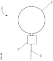
- the MRI coil includes a loop antenna. In embodiments, the MRI coil includes a butterfly antenna. In embodiments, the MRI coil includes a loop antenna and a butterfly antenna wherein in the loop antenna and the butterfly antenna are driven out of phase by 90 degrees with a phase shifter to create a circularly polarized magnetic field.
- the device and/or system includes a phase shifter.
- endorectal coils are used to improve the signal-to-noise ratio in a MRI image of the prostate. Typical MRI machines used on human subjects create a B0 field with a field strength commonly between about 1.5 and 3 Tesla.
- one antenna which can be used is a simple loop which in the orientation of the positioning device detects a magnetic field in y-axis.
- an antenna with butterfly configuration would detect in the x-axis.
- the signals detected by these two antenna are combined with a 90 degree phase shift between them. This allows the antenna to detect signals in both the x and y axes.
- the 90 degree phase shift is comprised of passive components and the signals can be combined, for example to increase signal-to-noise approximately by a square root of two.
- An exemplary 90° phase shift circuit is shown in Figure 30 .
- the imaging coil includes a loop antenna, matching components and a signal wire.
- the imaging coil includes a butterfly antenna, matching components and a signal wire.
- An exemplary matching circuit and components is shown in Figure 29 .
- the imaging coil includes the loop antenna, matching components, and a signal wire are interspaced with the butterfly antenna, matching components, and a signal wire. These dual antennas are driven with out of phase by 90 degrees with phase shifter.
- this composite imaging coil further includes a power splitter/combiner to manage the power and combine the signal from the loop antenna and the butterfly antenna.
- An exemplary power splitter combiner is shown in Figure 31 .
- the disclosed coils are receiving signal at 123.258 MHz on a 3 Tesla MRI machine.
- the antenna is driven by differential input.
- the antenna is driven by single ended input.
- the anatomical sensing system-guided prostate procedure device includes a flexible circuit that runs proximally from the imaging coil in the distal housing section through the mid housing section to the proximal housing section, where it couples to an interface board.
- the interface board is couplable to a complementary board on the sleeve.
- the materials of the flexible circuit are selected such that they are thin enough to pass through the construction at the mid housing section.
- the flexible circuit comprises thin metal strips on a polymer substrate.
- the metal comprises copper and the substrate comprises polyimide.
- the device and system are designed so that no dedicated software is likely to be required.
- Radiology images are routinely stored and viewed on a picture archiving and communication system (PACS). Irrespective of vendor, standard PACS tools should be sufficient for biopsy planning, since these allow calculation of required angulation in sagittal and oblique axial planes (multiplanar reformation and goniometer tools) and calculation of required needle insertion depth (linear distance measurement tool). These are routine three-dimensional tasks already familiar to any radiologist who performs image-guided biopsies.
- PACS picture archiving and communication system
- the disclosed device reduces prostate biopsy to a single procedure and allows for targeted collection of suspect tissue.
- the disclosed device is designed to be imaged by MRI concurrently with the cancerous tissue regions such that there is no need to fuse one imaging modality with another.
- the system includes an instrument for conducting a medical procedure.
- the instrument is a biopsy needle, a probe, sensor system, surgical device, therapeutic instrument system, or an agent placement device.
- the agent placement device includes a detachable marker, a dye/contrast agent, a drug, or a non-detachable marker.
- the instrument includes an anatomical sensing system detectable marker at a distal end.
- the instrument includes a depth indicator.
- the system further includes a clamp configured to retain the device stationary relative to the anatomical sensing system.
- the method includes: introducing the distal end of a disclosed anatomical sensing system-guided prostate procedure device into the rectum of a subject in proximity to a prostate of the subject; obtaining data on the anatomical features of the subject, including the prostate, and the anatomical sensing system-guided prostate procedure device using an anatomical sensing system; establishing the position of the device and the prostate; determining the location in three-dimensional space of tissue on or within the prostate for the procedure; translating the location in three-dimensional space to the instrument angle orienting system; and using the instrument angle orienting system to guide the instrument to the site of the prostate, thereby preforming the procedure.
- the procedure is a biopsy and the instrument is a biopsy needle, and wherein the tissue on or within the prostate is selected for biopsy at least partially by the data obtained with the imaging device, the method including obtaining a biopsy sample.
- the instrument comprises a biopsy needle, a probe, sensor system, surgical device, therapeutic instrument system, or an agent placement device.
- the agent placement device includes a detachable marker, a dye/contrast agent, a drug, or a non-detachable marker and the procedure includes placing the dye/contrast agent, the drug, or the non-detachable marker at the tissue on or within the prostate.
- the instrument includes an anatomical sensing system detectable marker at a distal end.
- the instrument includes a depth indicator.
- the method includes retaining the device stationary relative to the anatomical sensing system.
- the method includes obtaining images with the anatomical sensing system during the procedure.
- the method incudes introducing the distal end of the anatomical sensing system-guided prostate procedure device, such as disclosed herein into the rectum of a subject in proximity to a prostate of the subject and obtaining images of the device within the subject.
- the position of the device and the prostate is established.
- the method includes determining the location in three-dimensional space of tissue on or within the prostate for the procedure.
- the method includes translating the location in three-dimensional space of said tissue to the instrument angle orienting system.
- the method includes using the instrument angle orienting system to guide the instrument to the site of the prostate, thereby preforming the procedure.
- high quality endorectal images are obtained for both diagnosis and biopsy.
- images obtained during direct anatomical sensing system-guided biopsy are of lower quality than those obtained during the preceding diagnostic endorectal MRI.
- the target may not be well visualized and the operator may be forced to estimate target location based on correlation with more clearly visible anatomic landmarks such as the urethra, verumontanum, or distinctive nodules of benign prostatic hyperplasia.
- An aspect of the disclosed device is that it minimizes movement of target tissue during image acquisition and biopsy. Because the disclosed device remains stationary in the rectum during the procedure, the risk of prostate deformation and associated target displacement is minimized. This also improves image quality when compared to the industry standard balloon expandable endorectal coil, since anorectal contractions around this coil can result in motion artifact that degrades the quality of the endorectal MR images.
- the procedure is a biopsy and the instrument is a biopsy needle, and the tissue on or within the prostate is selected for biopsy at least partially by the images obtained with the imaging device, the method further comprising obtaining a biopsy sample.
- the instrument is a probe, or an agent placement device.
- the agent placement device includes a detachable marker, a dye/contrast agent, a drug, or a non-detachable marker and the procedure includes placing the dye/contrast agent, the drug, or the non-detachable marker at the tissue on or within the prostate.
- the instrument includes an anatomical sensing system detectable marker at a distal end.
- the instrument includes a depth indicator.
- the method includes retaining the device stationary relative to the anatomical sensing system.
- the method includes obtaining images with the anatomical sensing system during the procedure.
- the clinician has the option to perform either (or both) templated systematic sampling and/or target biopsy sampling of the prostate.
- the instrument angle orienting system is embodied as a curved array
- the curvature of the array better conforms to the shape of the prostate, thereby providing fuller coverage of potential target sites than attainable using a planar template.
- the distal end of the device remains stationary in the rectum for the entirety of the procedure. This eliminates the problem of prostate deformation during targeting of the biopsy needle, which would necessitate re-acquisition of patient images.
- one of the unique features of the disclosed device, system, and methods is that aspects of the device, including those elements of the housing or contained therein are disposable, while other components can be reused.
- the anatomical sensing system-guided prostate procedure device is disposable while elements downstream such as the clamp, compression ring and the electronic features can be reused.
- the housing of the anatomical sensing system-guided prostate procedure device and the compression ring for example, the parts of the system that come in contact with a subject, such as the anatomical sensing system-guided prostate procedure device, can be disposed of after use.
- the anatomical sensing system-guided prostate procedure device is made of non-costly materials.
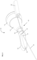
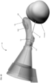
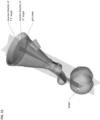
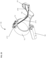
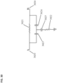
- Figures 1-3 show an embodiment of a disclosed anatomical sensing system-guided prostate procedure device based on a fixed curved array instrument angle orienting system, in accordance with this disclosure.
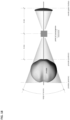
- Figure 1 shows a cross sectional view of an exemplary anatomical sensing system-guided prostate procedure device 100 using a fixed curved array instrument angle orienting system.
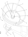
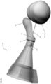
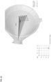
- Figure 2 shows a perspective view from the proximal aspect of the exemplary anatomical sensing system-guided prostate procedure device 100.
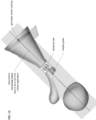
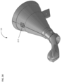
- Figure 3 shows a perspective view from the distal aspect of the anatomical sensing system-guided prostate procedure device 100.
- the device 100 includes a housing 102 comprised of three sections: a proximal housing section 115, a mid housing section 120, and a distal housing section 125.
- the proximal housing section 115 and mid housing section 120 are centered along a common longitudinal axis.
- the distal housing section 125 section is angled superiorly away from this axis.
- a compression sleeve 110 is fitted around the outer surface of the proximal housing section 115 and coupled to a clamp handle 105 on the inferior aspect of the device 100.
- the compression sleeve 110 may house power supply connections that mate with connections on the outside surface of the device 100, for example to power an MRI imaging coil (not shown) within the device or on the exterior surface of the device 100.
- the clamp handle 105 may be used fix the device 100 in a stationary position, for example, by clamping the clamp handle 105 to a table-mounted clamp stand (not shown).
- a curved grid array plate 150 having a convex proximal surface and a concave distal surface is situated within the proximal end of the proximal housing section 115 such that the convex proximal surface is accessible from outside the device 100.
- the curved grid array plate 150 is perforated by a plurality of biopsy needle access channels 155, each of which is cylindrical in shape and oriented such that the axes of all the access channels 155 converge distally to a common convergence point location 208.
- the grid array plate 150 may also have rotatable grid plate cover 160 having a pie-shaped cutout 165 to allow access to a subset of the access channels 155 from proximal-to-distal approach (see Figure 2 ).
- the rotatable grid plate cover 160 may be rotated manually about a bushing 175 at the center of the grid array plate 150 using a grid plate cover handle 170.
- the grid array plate 150 and its set of access channels 155 comprise a section of the instrument angle orienting system for the anatomical sensing system-guided prostate procedure device 100.
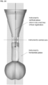
- the mid housing section 120 of the anatomical sensing system-guided prostate procedure device 100 comprises a recessed waist within which a spherical targeting ball 205 is housed as part of the instrument angle orienting system.
- the inner surface of the recessed waist has a spherical bearing surface 215, against which the spherical targeting ball 205, centered about a convergence point location 208, may rotate.
- the spherical bearing surface 215 may contain an anatomical sensing system visible agent compartment 220, for example a contrast agent, such as water/hydrogel, to provide image contrast during MRI imaging.
- This feature can be used as a fiducial marker during system registration and biopsy targeting, for example using imaging software the position of this feature of the device 100 can be used to define the location of the device in multiple dimensions, such as three-dimensions with respect to one or more of the patient, and the MRI system in which the device 100 is being used.
- the spherical targeting ball 205 has a conical cutout 210 on its proximal side and a fixed length needle guide 130 on its distal side.
- the distal tip 135 of the needle guide 130 may include an anatomical sensing system visible agent, for example a contrast agent such as water or hydrogel to cause contrast at that location during MRI imaging.
- the anatomical sensing system visible agent in the distal tip 135 of the needle guide 130 can be used as a fiducial marker during system registration and biopsy targeting, for example using imaging software the position of this feature of the device 100 can be used to define the location of the distal tip 135 of the needle guide 130 in multiple dimensions, such as three-dimensions with respect to one or more of the patient, and the MRI system in which the device 100 is being used.
- Figure 1 also depicts a biopsy needle 145 passing through one of the access channels 155 of the curved grid array plate 150, entering the conical cutout 210 of the spherical targeting ball 205, and exiting through the fixed length needle guide 130. While the biopsy needle 145 is shown passing through a central access channel 155, it is contemplated that the needle can pass through any of the access channels 155, Together, the access channels 155 of the curved grid array plate 150 and the rotatable spherical targeting ball 205 with the attached fixed length needle guide 130 allow the biopsy needle 145 to be aimed along discrete, predictable trajectories for biopsy targeting.
- the distal housing section 125 section of the anatomical sensing system-guided prostate procedure device 100 is angled superiorly away from the centerline of the proximal housing section 115 and mid housing section 120 sections. In embodiments, this angle may be between about 10 and about 45 degrees.
- the cross-section view of the distal housing section 125 in Figure 1 shows a distal tip coil compartment 305, an internal compartment within which an imaging coil may be placed to improve MRI imaging in the vicinity of the coil.
- a proximal coil 310 may also be attached to the external surface of the proximal housing section 115 to improve MRI imaging quality.
- a needle access cutout 140 from which the fixed length needle guide 130 and biopsy needle 145 are deployed. As shown in Figure 3 the biopsy needle 145 can be seen exiting the fixed length needle guide 130 at the needle access cutout 140.
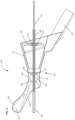
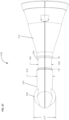
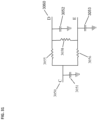
- Figures 4-6 shows an alternate unclaimed example of a prostate procedure device 400 utilizing a targeting scheme based on a continuously variable Cartesian coordinate instrument angle orienting system rather than a grid array template as shown in the device depicted in Figures 1-3 .
- Figure 4 shows a cross sectional view of an exemplary anatomical sensing system-guided prostate procedure device 400 based on a continuously variable Cartesian coordinate instrument angle orienting system.
- Figure 5 shows a perspective view from the proximal aspect of the exemplary anatomical sensing system-guided prostate procedure device 400.
- Figure 6 shows a perspective view from the distal aspect of the exemplary anatomical sensing system-guided prostate procedure device 400.
- the device 400 includes a housing 402 comprised of three sections: a proximal housing section 415, a mid housing section 420, and a distal housing section 425.
- the proximal housing section 415 and mid housing section 420 sections are centered along a common axis, and the distal housing section 425 section is angled superiorly away from this axis.
- no compression sleeve is shown and a clamp handle 405 is coupled to the inferior aspect of the device 400. This clamp handle 405 may be used fix the device 400 in a stationary position, for example, by clamping the clamp handle 405 to a table-mounted clamp stand (not shown).
- the proximal housing section 415 transitions from a round to a square cross-section as it expands proximally.
- This square cross-section is configured to house the continuously variable Cartesian coordinate instrument angle orienting system.
- the needle guide 505 passes through a pivot bearing 515 housed within a carriage 510 which is constrained to move along a linear rail assembly 520.
- the linear rail assembly 520 is constrained to move perpendicularly to the carriage 510 direction along a linear groove 530, effectively creating a two-axis linear guide system.
- This instrument angle orienting system allows the user to orient the needle guide along any desired trajectory by positioning the carriage 510 at the required Cartesian "XY" coordinates using a set of graduated markings 535.
- the mid housing section 420 section of the anatomical sensing system-guided prostate procedure device 100 comprises a recessed waist within which a spherical targeting ball 205 is housed as part of the instrument angle orienting system.
- the inner surface of the recessed waist has a spherical bearing surface 215, against which the spherical targeting ball 205, centered about a convergence point location 208, may rotate.
- the spherical bearing surface 215 may contain an anatomical sensing system visible agent compartment 220.
- the biopsy needle 145 travels through a needle guide 405 which extends the full length of the device housing and passes through a ball-biopsy needle targeting pivot assembly at the mid housing section.
- the distal housing section of the anatomical sensing system-guided prostate procedure device 400 is angled superiorly away from the centerline of the proximal housing section 415 and mid housing section 420 sections. In examples, this angle may be between about 10 and about 45 degrees.
- the cross-section view of the distal housing section 425 in Figure 4 shows a distal tip coil compartment 305, an internal compartment within which an imaging coil may be placed to improve MRI imaging in the vicinity of the coil.
- a needle access cutout 440 from which the fixed length needle guide 430 and biopsy needle 445 are deployed. As shown in figure 6 the biopsy needle 445 can be seen exiting the fixed length needle guide 430 at the needle access cutout 440.
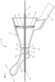
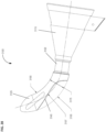
- Figures 7-9 shows an alternate unclaimed example of a prostate procedure device 400 utilizing a targeting scheme based on a continuously variable cylindrical coordinate instrument angle orienting system rather than a grid array template as shown in figures 1-3 or the Cartesian coordinate system depicted in figures 4-6 .
- Figure 7 shows a cross sectional view of an exemplary anatomical sensing system-guided prostate procedure device 700 based on a continuously variable cylindrical coordinate instrument angle orienting system.
- Figure 8 shows a perspective view from the proximal aspect of the anatomical sensing system-guided prostate procedure device 400.
- Figure 9 shows a perspective view from the distal aspect of the anatomical sensing system-guided prostate procedure device 400.
- the device 700 includes a housing 702 comprised of three sections: a proximal housing section 715, a mid housing section 720, and a distal housing section 725.
- the proximal housing section 715 and mid housing section 720 sections are centered along a common axis, and the distal housing section 725 section is angled superiorly away from this axis.
- no compression sleeve is shown and a clamp handle 705 is coupled to the inferior aspect of the device 700. This clamp handle 705 may be used fix the device 700 in a stationary position, for example, by clamping the clamp handle 705 to a table-mounted clamp stand (not shown).
- instrument angle orienting system of the device 700 comprises a circular plate 825 that is rotationally disposed within the proximal housing section, the circular plate 825 having a cutout guide 820 extending radially from its center.
- the needle guide 707 passes through a translating pivot bearing 815 which is slidably disposed within the cutout guide 820.
- Graduated markings representing radial position 830 and angular position 535 are used to a set of specify polar coordinates that position the proximal end of the needle guide 707 relative to a convergence point location 208 such that the biopsy needle 145 trajectory intersects the desired target tissue.
- the mid housing section 720 section of the anatomical sensing system-guided prostate procedure device 700 comprises a recessed waist within which a spherical targeting ball 205 is housed as part of the instrument angle orienting system.
- the inner surface of the recessed waist has a spherical bearing surface 215, against which the spherical targeting ball 205, centered about a convergence point location 208, may rotate.
- the spherical bearing surface 215 may contain an anatomical sensing system visible agent compartment 220.
- the biopsy needle 145 travels through a needle guide 707 which extends the full length of the device housing and passes through a ball-biopsy needle targeting pivot assembly at the mid housing section.
- the distal housing section 725 of the anatomical sensing system-guided prostate procedure device 700 is angled superiorly away from the centerline of the proximal housing section 715 and mid housing section 720 sections. In examples, this angle may be between about 10 and about 45 degrees.
- the cross-section view of the distal housing section 725 in Figure 7 shows a distal tip coil compartment 305, an internal compartment within which an imaging coil may be placed to improve MRI imaging in the vicinity of the coil.
- a needle access cutout 740 from which the fixed length needle guide 430 and biopsy needle 145 are deployed. As shown in figure 9 the biopsy needle 145 can be seen exiting the fixed length needle guide 707 at the needle access cutout 440.
- FIG 10 is partially transparent side perspective view of an embodiment of the disclosed anatomical sensing system-guided prostate procedure device 100 showing the placement of an imaging coil 1000 in the distal housing section 125.
- the imaging coil 1000 is configured to be placed within the compartment 305 of the distal hosing section 125.
- the imaging coil 1000 is situated endorectally and in close proximity to the prostate which increases the quality of MRI images of the prostate and surrounding tissue.
- the spherical targeting ball 205 the biopsy needle guide 130 and the biopsy needle 145.
- the biopsy needle 145 is depicted entering the prostate.
- Figure 11 is partially transparent side perspective view of an embodiment of the disclosed anatomical sensing system-guided prostate procedure device 100 showing the placement of an imaging coil 1100 at the proximal end of the distal housing section 125 of the device 100.
- the imaging coil 1100 is situated endorectally and in close proximity to the prostate which increases the quality of MRI images of the prostate and surrounding tissue.
- the spherical targeting ball 205 is shown in this view.
- the biopsy needle 145 is depicted entering the prostate.
- Figure 12 is partially transparent side perspective view of an embodiment of the disclosed anatomical sensing system-guided prostate procedure device 100 showing the placement of an imaging coil 1200 traversing the mid housing section 120 and the distal housing section 125 of the device 100.
- the imaging coil 1200 is situated endorectally and in close proximity to the prostate which increases the quality of MRI images of the prostate and surrounding tissue.
- the spherical targeting ball 205 is shown in this view.
- the biopsy needle 145 is depicted entering the prostate.
- aspects of the present disclosure concern anatomical sensing system-guided prostate biopsy using a disclosed device.
- the disclosed device is inserted into the patient's rectum and may be secured to the clamp-stand to prevent movement of the device.
- aspects of the methods are detailed in Figures 13-16 .
- MRI data is obtained and viewed perpendicular to the sagittal plane to identify and locate the anatomical sensing system-guided prostate procedure device's three principal targets.
- the three principal targets are the needle guide tip, the spherical targeting ball, and the grid plate center bushing. This identifies the anatomical sensing system-guided prostate procedure device's horizontal plane.
- MRI data is obtained and viewed perpendicular to instrument's horizontal plane to identify and locate the anatomical sensing system-guided prostate procedure device's three principal targets.
- the three principal targets are the needle guide tip, the spherical targeting ball, and the grid plate center bushing.
- MRI data is collected and viewed parallel to instrument's vertical plane.
- MRI image slices are stepped through to locate suspicious areas of the prostate for biopsy analysis. The position of these areas are locked and the angle between center of target and central axis of instrument is the measured and/or recorded. An angle of 10° is determined between the target and the horizontal plane.
- MRI data is collected and viewed parallel to instrument's horizontal plane.
- MRI image slices are stepped through to locate and suspicious areas of the prostate for biopsy analysis. The position of these areas are locked and the angle between center of target and central axis of instrument is the measured and/or recorded. An angle of 7.5° is determined between the target and the vertical plane.
- the angles derived as above are translated through the central axis of the instrument to the grid plate.
- the angle relative to the origin is located on the back of the grid plate.
- the angular distance between each guide hole is 2.5°.
- Each angle on the horizontal plane defines movement from side to side.
- Each angle on the vertical plane defines movement up and down.
- the needle target is three holes to the right and four holes down from the center origin.
- the value is rounded up or down to the closest 2.5° increment. For example, if the captured reading is 8°, round down to 7.5°. If the reading is 19°, round up to 20°.
- Figure 17 is a schematic side view of an anatomical sensing system-guided prostate procedure device superimposed on an image of the prostate and bowel of a subject. As shown, the device, when inserted, is situated a short distance from the prostate. Removing the needle access cutout illustrates that the probe is as close to the prostate as the anatomy allows.
- Figure 18 is a schematic top down view of the correspondence between the zone of prostate access and the intersection of the proximal and distal cones showing instrument range of motion, in accordance with various embodiments. As is shown in Figure 18 , the proximal and distal cones intersect at the convergence point, which is shown as a black box.
- Figure 19 is a schematic side view of the sections of the anatomical sensing system-guided prostate procedure device superimposed on an image of the prostate and bowel of a subject, in accordance with various embodiments.
- anatomical sensing system detectable markers can be used to determine the location of the components of the system relative to the anatomical features of a subject, such as the prostate of the subject.
- Figure 20 is a perspective of an anatomical sensing system-guided prostate procedure device shown in showing the power supply coupling for an imaging coil, in accordance with various embodiments.
- Figure 21 is a close up of showing the power supply coupling for an imaging coil, in accordance with various embodiments.
- Figure 22 is a perspective of a clamp ring for an anatomical sensing system-guided prostate procedure device shown in showing the power supply coupling for an imaging coil, in accordance with various embodiments.
- Figure 23 is a perspective view of an anatomical sensing system-guided prostate procedure device 100 showing a flex circuit 2715 and an imaging coil 2705, in accordance with various embodiments.
- the device 100 includes the proximal housing section 115, the mid housing section 120, and the distal housing section 125.
- a compression sleeve 110 is fitted around the outer surface of the proximal housing section 115 and coupled to a clamp handle 105 on the inferior aspect of the device 100.
- the compression sleeve 110 may house connections and/or electronics (see Figures 24-26 ) and mates with connections on the outside surface of the device 100.
- the clamp handle 105 may be used fix the device 100 in a stationary position, for example, by clamping the clamp handle 105 to a table-mounted clamp stand (not shown).
- the flexible circuit 2715 runs proximally from the imaging coil 2705 from the distal housing section 125 through the mid housing section 120 to the proximal housing section 115, where it couples to the interface board.
- the materials of the flexible circuit 2715 are selected such that they are thin enough to pass through the construction at the mid housing section 120.
- the flexible circuit 2715 comprises thin metal strips on a polymer substrate.
- the metal comprises copper and the substrate comprises polyimide.
- FIG 24 is a schematic of an imaging coil, in accordance with various embodiments.
- the imaging coil 2800 includes a loop antenna 2801, matching components 2802 and a signal wire 2803.
- the loop antenna 2801 creates a magnetic field that is primarily in the y-axis, where the B0 field (magnetic field) is assumed to be approximately parallel to the z-axis and the length of the human body, and the y-axis is the vertical axis and the x-axis is the horizontal axis perpendicular to the human body.
- the antenna is assumed to be approximately in the x-z plane where inserted into the rectum of a subject.
- FIG 25 is a schematic of an imaging coil, in accordance with various embodiments.
- the imaging coil 2900 includes a butterfly antenna 2901, matching components 2902 and a signal wire 2903.
- the butterfly antenna 2901 creates a magnetic field that is primarily in the x-axis, where the B0 field (magnetic field) is assumed to be approximately parallel to the z-axis and the length of the human body, and the y-axis is the vertical axis and the x-axis is the horizontal axis perpendicular to the human body.
- the antenna is assumed to be approximately in the x-z plane where inserted into the rectum of a subject.
- Figure 26 is a schematic of circularly polarized imaging composite coil 3000 made from the imaging coils of Figures 24 and 25 coupled together with selected electronics, in accordance with various embodiments.
- the loop antenna 2801, matching components 2802 and a signal wire 2803 are interspaced with the butterfly antenna 2901, matching components 2902 and a signal wire 2903.
- the loop antenna 2801 creates a magnetic field that is primarily in the y-axis, where the B0 field (magnetic field) is assumed to be approximately parallel to the z-axis and the length of the human body, and the y-axis is the vertical axis and the x-axis is the horizontal axis perpendicular to the human body.
- the butterfly antenna 2901 creates a magnetic field that is primarily in the x-axis. These dual antennas are driven with out of phase by 90 degrees with phase shifter 3010 to create a circularly polarized magnetic field. Using a coil in this configuration results in an approximately square root of 2 increase in signal-to-noise over a single antenna design.
- the imaging composite coil 3000 further includes a power splitter/combiner 3013 to manage the power and combine the signal from the loop antenna 2801 and the butterfly antenna 2901. The antenna is assumed to be approximately in the x-z plane where inserted into the rectum of a subject.
- Figures 27 and 28 detail aspects of the mid and distal housing sections, in accordance with certain embodiments.
- Figure 27 is a cross sectional side view of an anatomical sensing system-guided prostate procedure device, in accordance with various embodiments.
- Figure 28 a cross sectional side view of an anatomical sensing system-guided prostate procedure device, in accordance with various embodiments.
- the device 3100 includes a proximal housing section 3115, a mid housing section 3120, and a distal housing section 3125.
- the proximal housing section 3115 and mid housing section 120 are centered along a common longitudinal axis.
- the distal housing section 3125 section is angled superiorly away from this axis for example between about 10 to about 60 degrees away from the common longitudinal axis.
- the distal housing section 3125 may include a sub housing 3140 that is configured to contain an MRI imaging coil.
- the distal housing section 3125 has a width 3175, that is about 0.5 inches to about 1.5 inches.
- the sub housing has a width 3177 that is slightly larger than this.
- the mid housing section 3120 is recessed from both the distal housing section 3125 and the proximal housing section 3115 and configured to be retained in the anus of a subject, for example such that the anal orifice collapses around the recessed waist 3120 and helps to hold and/or retain the device in place.
- the mid housing section 3120 has a diameter 3180 that is about 0.25 inches to about 1.0 inches in length.
- the mid housing section 3120 has a length 3185 that is about 0.25 inches to about 1.0 inches in length.
- the device 3100 includes a proximal housing section 3115, a mid housing section 3120, and a distal housing section 3125.
- the proximal housing section 3115 and mid housing section 120 are centered along a common longitudinal axis.
- the distal housing section 3125 section is angled superiorly away from this axis for example between about 10 to about 60 degrees away from the common longitudinal axis.
- the distal housing section 3125 has a width 3175, that is about 0.5 inches to about 1.5 inches.
- the mid housing section 3120 is recessed from both the distal housing section 3125 and the proximal housing section 3115 and configured to be retained in the anus of a subject, for example such that the anal orifice collapses around the recessed waist 3120 and helps to hold and/or retain the device in place.
- the distal housing section has an internal radius 3195, an external radius, and a centerline radius 3197.
- the centerline radius 3197 is about 1.75 inches to about 2.25 inches.
- the internal radius 3190 is about 1.5 inches to about 1.9 inches.
- the external radius 3195 is about 2.25 inches to about 2.75 inches. Also shown in this view is the cut out 3140.
- FIG. 29 is a schematic of an exemplary matching circuit 2802 to be used between an input signal wire 2803 (depicted here as part of a grounded coaxial cable 2810) and a loop antenna 2801, in accordance with various embodiments.
- the matching network pictured here uses 3 capacitors 2811, 2812, 2813 to match the impedance of the driving signal to the impedance of the antenna 2801 in order maximize the power transfer.
- matching circuit components may be specified to impart a signal impedance of about 50 ohms. It will be recognized by those with skill in the electrical arts that other topologies and components can be used to match the signal input to the antenna. For example, inductors and or resistors can be used to construct a suitable matching circuit.
- Figure 30 is a schematic of an exemplary 90 degree phase shift circuit, as might be used for the phase shifter component 3010 in accordance with various embodiments.
- the signal input at node A 3020 is shifted by 90 degrees and appears at output node B 3030.
- the phase shifter circuit pictured here uses 2 inductors 3021, 3022 and three capacitors 3023, 3024, 3025. It will be recognized by those with skill
- phase shifter circuit for use in the disclosed system.
- the components of the 90 degree phase shifter maybe selected to impart a specific frequency of operation.
- phase shifter circuit components may be specified to impart a signal impedance of about 50 ohms.
- Figure 31 is a schematic of an exemplary power splitter combiner circuit, in accordance with various embodiments.
- a RF power splitter the input signal is attached at node C 3050 and half of the power appears at node D 3060 and the other half at node E 3070.
- the in phase signals that are on node D 3060 and node E 3070 are combined and are output on node C 3050.
- three capacitors 3051, 3052, 3053, two inductors 3055, 3056, and one resistor 3058 are used to create a power splitter combiner. It will be recognized by those with skill in the electrical arts that other topologies and components can be used to construct a power slitter combiner for use in the disclosed system.
- the components of power splitter combiner circuit may be specified to impart a signal impedance of about 50 ohms.
Claims (24)
- Dispositif (100) de traitement de la prostate guidé par un système de détection anatomique, comprenant :un boîtier (102) qui présente une extrémité proximale et une extrémité distale, le boîtier (102) comprenant une section de boîtier proximale (115), une section de boîtier intermédiaire (120) et une section de boîtier distale (125), la section de boîtier distale (125) étant configurée pour l'insertion dans un anus et la rétention dans un rectum d'un sujet ;un point de convergence d'instrument (208) qui est situé entre l'extrémité proximale et l'extrémité distale, le point de convergence d'instrument (208) étant défini par une intersection d'un cône proximal et d'un cône distal qui définit l'amplitude de mouvement d'un instrument (145) à la fois dans le sens proximal et dans le sens distal par rapport au point de convergence (208), et étant configuré de manière à permettre à l'instrument (145) de passer à travers le point de convergence d'instrument (208) suivant un angle variable et sélectionnable ;caractérisé en ce que la section de boîtier distale est inclinée au niveau supérieur en s'écartant de l'axe central des sections de boîtier proximale et intermédiaire ;et en ce que la section de boîtier distale comprend un compartiment de bobine d'IRM au niveau de l'extrémité distale ;et comprenant en outre :
un système d'orientation de l'angle de l'instrument à réseau fixe à l'extrémité proximale du boîtier (125) comprenant une pluralité de canaux d'accès à l'instrument uniformément espacés (155), chaque canal présentant un axe de canal et étant orienté de telle sorte que chacun des axes de canal converge en direction du point de convergence d'instrument (208). - Dispositif (100) de traitement de la prostate guidé par un système de détection anatomique selon la revendication 1, dans lequel le système d'orientation de l'angle de l'instrument à réseau fixe comprend une plaque de réseau de grille courbe (150) qui est disposée à l'intérieur de la section de boîtier proximale (115) ; et
dans lequel la pluralité de canaux d'accès à l'instrument uniformément espacés (155) comprend entre 100 et 200 canaux d'accès à l'instrument (155). - Dispositif (100) de traitement de la prostate guidé par un système de détection anatomique selon la revendication 1 ou selon la revendication 2, dans lequel la pluralité de canaux d'accès à l'instrument uniformément espacés (155) sont orientés suivant un motif en grille ou suivant un motif circulaire concentrique.
- Dispositif (100) de traitement de la prostate guidé par un système de détection anatomique selon l'une quelconque des revendications 1 à 3, dans lequel l'espacement entre la pluralité de canaux d'accès à l'instrument uniformément espacés (155) est compris entre 1 degré et 5 degrés, tel qu'il est mesuré à partir de l'axe central des sections de boîtier proximale (115) et intermédiaire (120).
- Dispositif (100) de traitement de la prostate guidé par un système de détection anatomique selon l'une quelconque des revendications 1 à 4, comprenant en outre un carter de plaque de grille rotatif (160) qui comporte une découpe (165) destinée à permettre à l'instrument (145) d'accéder à un sous-ensemble de la pluralité de canaux d'accès à l'instrument uniformément espacés (155).
- Dispositif (100) de traitement de la prostate guidé par un système de détection anatomique selon l'une quelconque des revendications 1 à 5, dans lequel le point de convergence d'instrument (208) est contenu à l'intérieur d'un mécanisme qui est configuré de manière à diriger l'instrument en direction d'emplacements tridimensionnels dans le sens distal.
- Dispositif (100) de traitement de la prostate guidé par un système de détection anatomique selon l'une quelconque des revendications 1 à 6, dans lequel le système d'orientation de l'angle de l'instrument à réseau fixe oriente une profondeur de pénétration d'une extrémité distale de l'instrument (145) et/ou un emplacement en trois dimensions de l'extrémité distale de l'instrument (145).
- Dispositif (100) de traitement de la prostate guidé par un système de détection anatomique selon l'une quelconque des revendications 1 à 7, comprenant en outre un guide d'instrument (130), qui est optionnellement sensiblement cylindrique et qui permet à l'instrument (145) de passer à travers le dispositif (100) de traitement de la prostate guidé par un système de détection anatomique.
- Dispositif (100) de traitement de la prostate guidé par un système de détection anatomique selon l'une quelconque des revendications 1 à 8, dans lequel le point de convergence (208) peut être déplacé le long d'un axe qui s'étend à partir de l'extrémité proximale du dispositif (100) jusqu'à l'extrémité distale du dispositif (100).
- Dispositif (100) de traitement de la prostate guidé par un système de détection anatomique selon l'une quelconque des revendications 1 à 9, dans lequel la section de boîtier intermédiaire (120) comprend en outre une bille de ciblage sphérique (205) contrainte en rotation à l'intérieur de la section de boîtier intermédiaire (120) et centrée autour du point de convergence d'instrument (208), dans lequel la bille de ciblage sphérique (205) comporte optionnellement une découpe conique (210) sur un côté proximal qui est configurée de manière à recevoir l'instrument (145) qui passe à travers celle-ci.
- Dispositif (100) de traitement de la prostate guidé par un système de détection anatomique selon la revendication 10, dans lequel le guide d'instrument (130) s'étend à partir du côté distal de la bille de ciblage sphérique (205) et/ou dans lequel le guide d'instrument (130) s'étend à partir du côté proximal de la bille de ciblage sphérique (205) et dans lequel, optionnellement, le guide d'instrument (130) est réglable et peut être positionné contre la paroi extérieure du rectum à proximité de la prostate.
- Dispositif (100) de traitement de la prostate guidé par un système de détection anatomique selon l'une quelconque des revendications 1 à 11, dans lequel le système de détection anatomique comprend un système de détection anatomique par résonance magnétique, un système de détection anatomique par tomodensitométrie (TDM) ou un système de détection anatomique par ultrasons.
- Dispositif (100) de traitement de la prostate guidé par un système de détection anatomique selon l'une quelconque des revendications 1 à 12, dans lequel l'instrument (145) comprend une aiguille de biopsie, une sonde, un système de capteur, un dispositif chirurgical, un système d'instrument thérapeutique ou un dispositif de placement d'agent ; et
dans lequel le dispositif de placement d'agent comprend optionnellement un marqueur détachable, un colorant/agent de contraste, un médicament ou un marqueur non détachable. - Dispositif (100) de traitement de la prostate guidé par un système de détection anatomique selon l'une quelconque des revendications 1 à 13, comprenant en outre au moins une bobine d'IRM.
- Dispositif (100) de traitement de la prostate guidé par un système de détection anatomique selon la revendication 14, dans lequel ladite au moins une bobine d'IRM comprend une bobine d'IRM (1000) qui est disposée à l'intérieur du compartiment (305) de bobine d'IRM au niveau de l'extrémité distale.
- Dispositif (100) de traitement de la prostate guidé par un système de détection anatomique selon la revendication 14, dans lequel ladite au moins une bobine d'IRM comprend une bobine d'IRM qui est disposée sur une surface intérieure de l'extrémité proximale (1100) du boîtier ou qui traverse la section de boîtier distale et la section de boîtier intermédiaire (1200).
- Dispositif (100) de traitement de la prostate guidé par un système de détection anatomique selon l'une quelconque des revendications 14 à 16, dans lequel ladite au moins une bobine d'IRM comprend une antenne cadre (2801) et/ou une antenne papillon (2901), dans lequel l'antenne cadre (2801) et l'antenne papillon (2901) sont entraînées à 90 degrés hors phase à l'aide d'un déphaseur (3010) dans le but de créer un champ magnétique à polarisation circulaire.
- Dispositif (100) de traitement de la prostate guidé par un système de détection anatomique selon l'une quelconque des revendications 1 à 17, comprenant en outre une poignée de serrage (105) qui est couplée à la section de boîtier proximale (115) et/ou un anneau de compression (110) qui est couplé à la section de boîtier proximale (115).
- Dispositif (100) de traitement de la prostate guidé par un système de détection anatomique selon l'une quelconque des revendications 1 à 18, comprenant en outre un ou plusieurs point(s) d'un agent détectable du système de détection anatomique qui permet(tent) de localiser le dispositif par rapport au système de détection anatomique, tel qu'un ou plusieurs éléments parmi les éléments suivants : un plastique, tel qu'un polycarbonate, un mélange ABS/polycarbonate, un polyester ou un nylon, optionnellement dopé avec du sulfate de baryum et/ou du dioxyde de titane ; un métal, tel que l'or, le tantale, le platine, le tungstène, le titane, le cobalt-chrome, l'acier inoxydable, le fer-chrome-nickel, le zirconium et leurs alliages ; un agent de contraste liquide ; l'eau ; un hydrogel ; un tissage ou un motif de fils minces ; ou des combinaisons de ceux-ci.
- Dispositif (100) de traitement de la prostate guidé par un système de détection anatomique selon la revendication 19, dans lequel un ou plusieurs des points de l'agent détectable du système de détection anatomique est (sont) situé(s) à une extrémité distale du guide d'instrument (130), au point de convergence (208) et/ou au niveau d'un centre du système d'orientation de l'angle de l'instrument à réseau fixe.
- Dispositif (100) de traitement de la prostate guidé par un système de détection anatomique selon l'une quelconque des revendications 1 à 20, comprenant en outre un ou plusieurs composant(s) d'adaptation, et/ou un répartiteur de puissance et/ou un combineur de signaux.
- Dispositif (100) de traitement de la prostate guidé par un système de détection anatomique selon l'une quelconque des revendications 1 à 21, dans lequel la section de boîtier distale (125) comporte une découpe (140) dans la partie inférieure de la section de boîtier distale (125) qui permet à l'instrument (145) de passer à travers le dispositif (100) et qui correspond au cône distal qui définit le mouvement de l'instrument (145).
- Dispositif (100) de traitement de la prostate guidé par un système de détection anatomique selon l'une quelconque des revendications 1 à 22, dans lequel la section de boîtier distale (125) est inclinée au niveau supérieur en s'écartant de l'axe central du boîtier (102) suivant un angle qui est compris entre 10 degrés et 60 degrés, et est configurée de manière à épouser la forme en J du rectum humain, et/ou dans lequel les surfaces distales de la section de boîtier distale (125) sont arrondies dans le but de faciliter l'insertion et la protection des tissus anaux et rectaux.
- Système de détection anatomique, comprenant le dispositif (100) selon l'une quelconque des revendications 1 à 23 et un instrument (145) pour exécuter une procédure médicale, et optionnellement une pince qui est configurée de manière à maintenir le dispositif (100) stationnaire par rapport au système de détection anatomique, dans lequel optionnellement l'instrument (145) comprend un indicateur de profondeur.
Applications Claiming Priority (2)
| Application Number | Priority Date | Filing Date | Title |
|---|---|---|---|
| US201662382631P | 2016-09-01 | 2016-09-01 | |
| PCT/US2017/049954 WO2018045342A1 (fr) | 2016-09-01 | 2017-09-01 | Dispositif de biopsie endorectale de la prostate guidée par système de détection anatomique |
Publications (4)
| Publication Number | Publication Date |
|---|---|
| EP3506835A1 EP3506835A1 (fr) | 2019-07-10 |
| EP3506835A4 EP3506835A4 (fr) | 2020-04-29 |
| EP3506835C0 EP3506835C0 (fr) | 2023-08-02 |
| EP3506835B1 true EP3506835B1 (fr) | 2023-08-02 |
Family
ID=61301601
Family Applications (1)
| Application Number | Title | Priority Date | Filing Date |
|---|---|---|---|
| EP17847654.5A Active EP3506835B1 (fr) | 2016-09-01 | 2017-09-01 | Dispositif de biopsie endorectale de la prostate guidée par système de détection anatomique |
Country Status (6)
| Country | Link |
|---|---|
| US (1) | US11464499B2 (fr) |
| EP (1) | EP3506835B1 (fr) |
| JP (1) | JP7021196B2 (fr) |
| CA (1) | CA3035444A1 (fr) |
| ES (1) | ES2961752T3 (fr) |
| WO (1) | WO2018045342A1 (fr) |
Families Citing this family (3)
| Publication number | Priority date | Publication date | Assignee | Title |
|---|---|---|---|---|
| US11093038B2 (en) | 2019-05-14 | 2021-08-17 | Synchron Australia Pty Limited | Systems and methods for generic control using a neural signal |
| KR102288184B1 (ko) * | 2019-06-04 | 2021-08-09 | 한양대학교 산학협력단 | 전립선 검사장치 및 전립선 질환 진단정보 제공방법 |
| US11759232B2 (en) * | 2021-03-14 | 2023-09-19 | Sang E Sim | Needle guide template for perirectal spacer and fiducial marker placement |
Citations (2)
| Publication number | Priority date | Publication date | Assignee | Title |
|---|---|---|---|---|
| US20100324445A1 (en) * | 2009-06-17 | 2010-12-23 | Mollere Rebecca J | MRI Biopsy Cylindraceous Targeting Guide |
| US20150065886A1 (en) * | 2012-04-10 | 2015-03-05 | Trhe Johns Hopkins University | Cohesive robot-ultrasound probe for prostate biopsy |
Family Cites Families (14)
| Publication number | Priority date | Publication date | Assignee | Title |
|---|---|---|---|---|
| JPH10155730A (ja) * | 1996-11-28 | 1998-06-16 | Olympus Optical Co Ltd | Mri観察用チューブ |
| US6470204B1 (en) | 1999-08-25 | 2002-10-22 | Egidijus Edward Uzgiris | Intracavity probe for MR image guided biopsy and delivery of therapy |
| CA2404352A1 (fr) * | 2000-03-24 | 2001-10-04 | Ergin Atalar | Dispositif, systemes et procedes d'imagerie par resonance magnetique in vivo |
| US6464691B1 (en) | 2000-10-11 | 2002-10-15 | Popcab, Llc | Port device for port off-pump beating heart coronary artery bypass surgery system |
| US8123697B2 (en) | 2002-02-14 | 2012-02-28 | Koninklijke Philips Electronics N.V. | Method and apparatus for MR-guided biopsy |
| EP1374949B1 (fr) | 2002-06-17 | 2005-12-14 | Nucletron B.V. | Système en temps réel pour la planification de traitement d'irradiation par rayonnement |
| WO2007106558A2 (fr) * | 2006-03-14 | 2007-09-20 | The Johns Hopkins University | Appareil d'insertion d'un dispositif medical dans un corps au cours d'une procedure d'imagerie medicale, et dispositifs et procedes associes |
| DE102007023478A1 (de) | 2007-01-12 | 2008-07-17 | Stabilus Gmbh | Anschlusselement zum Verbinden von Bauteilen |
| WO2014058833A1 (fr) * | 2012-10-08 | 2014-04-17 | The Johns Hopkins University | Robot sans risque pour une irm pour permettre une biopsie transrectale de la prostate |
| SG2012091609A (en) * | 2012-12-11 | 2014-07-30 | Biobot Surgical Pte Ltd | An apparatus and method for biopsy and therapy |
| US10274553B2 (en) | 2013-03-15 | 2019-04-30 | Canon U.S.A., Inc. | Needle placement manipulator with attachment for RF-coil |
| DE102014207731A1 (de) * | 2013-11-13 | 2015-05-28 | Siemens Aktiengesellschaft | Sendeantenneneinrichtung und Magnetresonanztomographieanlage |
| JP2015104602A (ja) | 2013-12-02 | 2015-06-08 | 株式会社東芝 | 体腔内プローブ及び超音波診断装置 |
| EP3365060B1 (fr) | 2015-10-21 | 2020-03-25 | Koninklijke Philips N.V. | Système prenant en charge le traitement d'un sujet |
-
2017
- 2017-09-01 JP JP2019512312A patent/JP7021196B2/ja active Active
- 2017-09-01 CA CA3035444A patent/CA3035444A1/fr active Pending
- 2017-09-01 EP EP17847654.5A patent/EP3506835B1/fr active Active
- 2017-09-01 ES ES17847654T patent/ES2961752T3/es active Active
- 2017-09-01 US US16/329,061 patent/US11464499B2/en active Active
- 2017-09-01 WO PCT/US2017/049954 patent/WO2018045342A1/fr unknown
Patent Citations (2)
| Publication number | Priority date | Publication date | Assignee | Title |
|---|---|---|---|---|
| US20100324445A1 (en) * | 2009-06-17 | 2010-12-23 | Mollere Rebecca J | MRI Biopsy Cylindraceous Targeting Guide |
| US20150065886A1 (en) * | 2012-04-10 | 2015-03-05 | Trhe Johns Hopkins University | Cohesive robot-ultrasound probe for prostate biopsy |
Also Published As
| Publication number | Publication date |
|---|---|
| EP3506835C0 (fr) | 2023-08-02 |
| EP3506835A1 (fr) | 2019-07-10 |
| WO2018045342A1 (fr) | 2018-03-08 |
| EP3506835A4 (fr) | 2020-04-29 |
| US11464499B2 (en) | 2022-10-11 |
| US20190192125A1 (en) | 2019-06-27 |
| JP7021196B2 (ja) | 2022-02-16 |
| ES2961752T3 (es) | 2024-03-13 |
| CA3035444A1 (fr) | 2018-03-08 |
| JP2019528851A (ja) | 2019-10-17 |
Similar Documents
| Publication | Publication Date | Title |
|---|---|---|
| US10327805B2 (en) | Biopsy cannula adjustable depth stop | |
| CA2631989C (fr) | Bloc de guidage pour dispositifs de biopsie ou chirurgicaux | |
| US10123820B2 (en) | Grid and rotatable cube guide localization fixture for biopsy device | |
| US7722565B2 (en) | Access system | |
| US6731966B1 (en) | Systems and methods for targeting a lesion | |
| JP2004033751A (ja) | Mri適合性生検装置用の位置決め機構 | |
| EP3506835B1 (fr) | Dispositif de biopsie endorectale de la prostate guidée par système de détection anatomique | |
| US7014643B2 (en) | Apparatus for endorectal prostate biopsy | |
| WO2000065989A1 (fr) | Systemes et procedes permettant de cibler une lesion du sein | |
| JP2019528851A5 (fr) | ||
| US20230028963A1 (en) | Device for anatomical sensing system-guided endorectal prostate biopsy | |
| US20200214591A1 (en) | A Medical Imaging System and Method | |
| Larson et al. | A robotic device for minimally invasive breast interventions with real-time MRI guidance | |
| US20230134815A1 (en) | Guidance system for interventional devices with curved shape |
Legal Events
| Date | Code | Title | Description |
|---|---|---|---|
| STAA | Information on the status of an ep patent application or granted ep patent |
Free format text: STATUS: THE INTERNATIONAL PUBLICATION HAS BEEN MADE |
|
| PUAI | Public reference made under article 153(3) epc to a published international application that has entered the european phase |
Free format text: ORIGINAL CODE: 0009012 |
|
| STAA | Information on the status of an ep patent application or granted ep patent |
Free format text: STATUS: REQUEST FOR EXAMINATION WAS MADE |
|
| 17P | Request for examination filed |
Effective date: 20190301 |
|
| AK | Designated contracting states |
Kind code of ref document: A1 Designated state(s): AL AT BE BG CH CY CZ DE DK EE ES FI FR GB GR HR HU IE IS IT LI LT LU LV MC MK MT NL NO PL PT RO RS SE SI SK SM TR |
|
| AX | Request for extension of the european patent |
Extension state: BA ME |
|
| DAV | Request for validation of the european patent (deleted) | ||
| DAX | Request for extension of the european patent (deleted) | ||
| A4 | Supplementary search report drawn up and despatched |
Effective date: 20200327 |
|
| RIC1 | Information provided on ipc code assigned before grant |
Ipc: A61B 5/055 20060101ALI20200324BHEP Ipc: A61B 10/02 20060101AFI20200324BHEP Ipc: A61B 17/34 20060101ALI20200324BHEP Ipc: A61B 90/00 20160101ALI20200324BHEP Ipc: A61B 17/00 20060101ALI20200324BHEP Ipc: A61B 90/11 20160101ALI20200324BHEP Ipc: A61B 6/03 20060101ALI20200324BHEP |
|
| GRAP | Despatch of communication of intention to grant a patent |
Free format text: ORIGINAL CODE: EPIDOSNIGR1 |
|
| STAA | Information on the status of an ep patent application or granted ep patent |
Free format text: STATUS: GRANT OF PATENT IS INTENDED |
|
| INTG | Intention to grant announced |
Effective date: 20230224 |
|
| GRAS | Grant fee paid |
Free format text: ORIGINAL CODE: EPIDOSNIGR3 |
|
| GRAA | (expected) grant |
Free format text: ORIGINAL CODE: 0009210 |
|
| STAA | Information on the status of an ep patent application or granted ep patent |
Free format text: STATUS: THE PATENT HAS BEEN GRANTED |
|
| AK | Designated contracting states |
Kind code of ref document: B1 Designated state(s): AL AT BE BG CH CY CZ DE DK EE ES FI FR GB GR HR HU IE IS IT LI LT LU LV MC MK MT NL NO PL PT RO RS SE SI SK SM TR |
|
| REG | Reference to a national code |
Ref country code: GB Ref legal event code: FG4D |
|
| REG | Reference to a national code |
Ref country code: CH Ref legal event code: EP |
|
| REG | Reference to a national code |
Ref country code: DE Ref legal event code: R096 Ref document number: 602017072271 Country of ref document: DE |
|
| REG | Reference to a national code |
Ref country code: IE Ref legal event code: FG4D |
|
| U01 | Request for unitary effect filed |
Effective date: 20230831 |
|
| U07 | Unitary effect registered |
Designated state(s): AT BE BG DE DK EE FI FR IT LT LU LV MT NL PT SE SI Effective date: 20230907 |
|
| U20 | Renewal fee paid [unitary effect] |
Year of fee payment: 7 Effective date: 20230907 |
|
| PGFP | Annual fee paid to national office [announced via postgrant information from national office to epo] |
Ref country code: GB Payment date: 20230811 Year of fee payment: 7 |
|
| PG25 | Lapsed in a contracting state [announced via postgrant information from national office to epo] |
Ref country code: GR Free format text: LAPSE BECAUSE OF FAILURE TO SUBMIT A TRANSLATION OF THE DESCRIPTION OR TO PAY THE FEE WITHIN THE PRESCRIBED TIME-LIMIT Effective date: 20231103 |
|
| PGFP | Annual fee paid to national office [announced via postgrant information from national office to epo] |
Ref country code: ES Payment date: 20231031 Year of fee payment: 7 |
|
| PG25 | Lapsed in a contracting state [announced via postgrant information from national office to epo] |
Ref country code: IS Free format text: LAPSE BECAUSE OF FAILURE TO SUBMIT A TRANSLATION OF THE DESCRIPTION OR TO PAY THE FEE WITHIN THE PRESCRIBED TIME-LIMIT Effective date: 20231202 |
|
| PG25 | Lapsed in a contracting state [announced via postgrant information from national office to epo] |
Ref country code: RS Free format text: LAPSE BECAUSE OF FAILURE TO SUBMIT A TRANSLATION OF THE DESCRIPTION OR TO PAY THE FEE WITHIN THE PRESCRIBED TIME-LIMIT Effective date: 20230802 Ref country code: NO Free format text: LAPSE BECAUSE OF FAILURE TO SUBMIT A TRANSLATION OF THE DESCRIPTION OR TO PAY THE FEE WITHIN THE PRESCRIBED TIME-LIMIT Effective date: 20231102 Ref country code: IS Free format text: LAPSE BECAUSE OF FAILURE TO SUBMIT A TRANSLATION OF THE DESCRIPTION OR TO PAY THE FEE WITHIN THE PRESCRIBED TIME-LIMIT Effective date: 20231202 Ref country code: HR Free format text: LAPSE BECAUSE OF FAILURE TO SUBMIT A TRANSLATION OF THE DESCRIPTION OR TO PAY THE FEE WITHIN THE PRESCRIBED TIME-LIMIT Effective date: 20230802 Ref country code: GR Free format text: LAPSE BECAUSE OF FAILURE TO SUBMIT A TRANSLATION OF THE DESCRIPTION OR TO PAY THE FEE WITHIN THE PRESCRIBED TIME-LIMIT Effective date: 20231103 |
|
| PG25 | Lapsed in a contracting state [announced via postgrant information from national office to epo] |
Ref country code: PL Free format text: LAPSE BECAUSE OF FAILURE TO SUBMIT A TRANSLATION OF THE DESCRIPTION OR TO PAY THE FEE WITHIN THE PRESCRIBED TIME-LIMIT Effective date: 20230802 |
|
| REG | Reference to a national code |
Ref country code: ES Ref legal event code: FG2A Ref document number: 2961752 Country of ref document: ES Kind code of ref document: T3 Effective date: 20240313 |