EP3506414B1 - Jig device for inspecting quality of secondary battery - Google Patents
Jig device for inspecting quality of secondary battery Download PDFInfo
- Publication number
- EP3506414B1 EP3506414B1 EP18825160.7A EP18825160A EP3506414B1 EP 3506414 B1 EP3506414 B1 EP 3506414B1 EP 18825160 A EP18825160 A EP 18825160A EP 3506414 B1 EP3506414 B1 EP 3506414B1
- Authority
- EP
- European Patent Office
- Prior art keywords
- module
- secondary battery
- gliding
- support part
- jig
- Prior art date
- Legal status (The legal status is an assumption and is not a legal conclusion. Google has not performed a legal analysis and makes no representation as to the accuracy of the status listed.)
- Active
Links
Images


Classifications
-
- H—ELECTRICITY
- H01—ELECTRIC ELEMENTS
- H01M—PROCESSES OR MEANS, e.g. BATTERIES, FOR THE DIRECT CONVERSION OF CHEMICAL ENERGY INTO ELECTRICAL ENERGY
- H01M10/00—Secondary cells; Manufacture thereof
- H01M10/42—Methods or arrangements for servicing or maintenance of secondary cells or secondary half-cells
- H01M10/4285—Testing apparatus
-
- B—PERFORMING OPERATIONS; TRANSPORTING
- B23—MACHINE TOOLS; METAL-WORKING NOT OTHERWISE PROVIDED FOR
- B23K—SOLDERING OR UNSOLDERING; WELDING; CLADDING OR PLATING BY SOLDERING OR WELDING; CUTTING BY APPLYING HEAT LOCALLY, e.g. FLAME CUTTING; WORKING BY LASER BEAM
- B23K37/00—Auxiliary devices or processes, not specially adapted to a procedure covered by only one of the preceding main groups
- B23K37/04—Auxiliary devices or processes, not specially adapted to a procedure covered by only one of the preceding main groups for holding or positioning work
- B23K37/0426—Fixtures for other work
- B23K37/0435—Clamps
- B23K37/0443—Jigs
-
- G—PHYSICS
- G01—MEASURING; TESTING
- G01M—TESTING STATIC OR DYNAMIC BALANCE OF MACHINES OR STRUCTURES; TESTING OF STRUCTURES OR APPARATUS, NOT OTHERWISE PROVIDED FOR
- G01M3/00—Investigating fluid-tightness of structures
- G01M3/02—Investigating fluid-tightness of structures by using fluid or vacuum
- G01M3/04—Investigating fluid-tightness of structures by using fluid or vacuum by detecting the presence of fluid at the leakage point
- G01M3/24—Investigating fluid-tightness of structures by using fluid or vacuum by detecting the presence of fluid at the leakage point using infrasonic, sonic, or ultrasonic vibrations
-
- G—PHYSICS
- G01—MEASURING; TESTING
- G01R—MEASURING ELECTRIC VARIABLES; MEASURING MAGNETIC VARIABLES
- G01R1/00—Details of instruments or arrangements of the types included in groups G01R5/00 - G01R13/00 and G01R31/00
- G01R1/02—General constructional details
- G01R1/04—Housings; Supporting members; Arrangements of terminals
-
- H—ELECTRICITY
- H01—ELECTRIC ELEMENTS
- H01M—PROCESSES OR MEANS, e.g. BATTERIES, FOR THE DIRECT CONVERSION OF CHEMICAL ENERGY INTO ELECTRICAL ENERGY
- H01M10/00—Secondary cells; Manufacture thereof
- H01M10/42—Methods or arrangements for servicing or maintenance of secondary cells or secondary half-cells
- H01M10/4228—Leak testing of cells or batteries
-
- Y—GENERAL TAGGING OF NEW TECHNOLOGICAL DEVELOPMENTS; GENERAL TAGGING OF CROSS-SECTIONAL TECHNOLOGIES SPANNING OVER SEVERAL SECTIONS OF THE IPC; TECHNICAL SUBJECTS COVERED BY FORMER USPC CROSS-REFERENCE ART COLLECTIONS [XRACs] AND DIGESTS
- Y02—TECHNOLOGIES OR APPLICATIONS FOR MITIGATION OR ADAPTATION AGAINST CLIMATE CHANGE
- Y02E—REDUCTION OF GREENHOUSE GAS [GHG] EMISSIONS, RELATED TO ENERGY GENERATION, TRANSMISSION OR DISTRIBUTION
- Y02E60/00—Enabling technologies; Technologies with a potential or indirect contribution to GHG emissions mitigation
- Y02E60/10—Energy storage using batteries
Definitions
- the present invention relates to a jig device for inspecting quality of a secondary battery, which is capable of fixing the secondary battery when a sealed state of a sealing part of the secondary battery is inspected while or after the secondary battery is produced.
- rechargeable secondary batteries are being developed not only for digital devices but also for vehicles such as electric vehicles.
- Secondary batteries are variously classified according to materials and shapes of a positive electrode and a negative electrode. Among them, since such a lithium secondary battery using a lithium compound material has large capacity and a low self-discharge rate, the lithium secondary battery is being widely used instead of a nickel-cadmium secondary battery according to the related art.
- the lithium secondary battery may be manufactured in various shapes.
- Representative examples of the shape of the lithium secondary battery include a cylinder type lithium secondary battery and a prismatic type lithium secondary battery.
- a pouch type lithium secondary battery having flexibility is being manufactured.
- the pouch type secondary battery comprises a pouch and an electrode assembly built in the pouch to charge and discharge electric energy.
- An electrolyte is injected into the pouch in a state in which the pouch is opened.
- An electrode tab protruding from an end of the electrode assembly is connected to a lead that protrudes outward from the pouch 11.
- a sealing part that is sealed to seal the pouch is disposed along an edge of the pouch. That is, the sealing part may be an edge portion that is thinner than a portion, in which the electrode assembly is built, within the pouch.
- a pouch sealant is applied to an adhesion surface of the sealing part
- a tab sealant is applied to an adhesion surface of the electrode tab. Also, as described above, when the applied pouch and tab sealants are heated and melted by a sealing tool, the sealing of the sealing part of the pouch may be performed.
- KR 2015 0049462 and US 3 508 806 disclose a jig apparatus.
- a quality inspection of the sealing part may be additionally performed by using ultrasonic waves.
- the present applicant had filed an application on July 12, 2016, entitled “an apparatus and method for inspecting sealability of a pouch type secondary battery” (Patent Application No. 10-2016-0087925 ).
- the apparatus for inspecting the sealability as described above comprises an irradiating device irradiating ultrasonic waves, a receiving device receiving the ultrasonic waves, a measuring device measuring transmittance of the ultrasonic waves.
- the ultrasonic waves are irradiated onto the sealing part to measure the sealability of the sealing part.
- the pouch type secondary battery has to be fixed to a fixed body to prevent the sealing from moving and being shaken while the ultrasonic measurement is performed.
- the present applicant has developed a jig device for inspecting quality of the secondary battery as the fixed body for fixing the secondary battery as illustrated in FIG. 1 .
- the jig device 1 is disposed on a lower portion of a gliding device 4 on which an ultrasonic irradiating device 5 is mounted to fix the secondary battery 3.
- the gliding device 4 is constituted by gliding mechanisms 4a and 4b, which are glided in x and y directions and coupled to each other, to fix the secondary battery 3 while the irradiating device 5 moves in the x and y directions.
- the jig device 1 is glided so that gliding-side sides 1a and 1b come into contact with the sealing part of the secondary battery 3 when the secondary battery 3 is seated on a fixed-side side 2 within the jig device 1.
- the gliding of the gliding-side sides 1a and 1b is controlled by hand drive bolts 2a and 2b.
- the jig device 1 has to be individually manufactured in various sizes and standards according to a size and standard of the secondary battery.
- an object of the present invention is to provide a jig device for inspecting quality of a secondary battery, which is capable of fixing the secondary battery having various sizes (while various types of quality inspections are performed to confirm sealability of a sealing part).
- the present invention provides a jig device comprising an ultrasonic inspection device for inspecting quality of a secondary battery as defined in the appended set of claims, the jig device, which fixes the secondary battery and inspects quality of the secondary battery, the jig device comprising: a jig base having a plate shape and a seating hole; a fixed module mounted on the jig base at one side of the seating hole; a first gliding module mounted on the jig base at a side opposite to the fixed module and glidable toward the fixed module; and a support part extending across the seating hole, the support part having a first end connected to the fixed module and a second end connected to the first gliding module and on which the secondary battery is placed, wherein a masking block is mounted on one or more portions of the fixed module and the first gliding module, which comes into contact with an edge of the secondary battery when placed on the support part, and when the masking block contacts the edge of the secondary
- the fixed module may be detachable from the jig base.
- a wall part protrudes upward along a circumference of the jig base, and a second gliding module that is glidable in a direction perpendicular to the first gliding module is mounted on any one position of the wall part.
- Another masking block is detachably mounted on a portion of the second gliding module, which comes into contact with the edge of the secondary battery.
- An additional masking block is detachably mounted on the wall part opposite to the another masking block such that, when the secondary battery is moved by the second gliding module, the additional masking block comes into contact with the secondary battery.
- each of the first gliding module and the second gliding module may be adjusted according to a rotation direction of a hand drive bolt, the hand drive bolt being screw-coupled to pass through the wall part.
- Each hand drive bolt may be provided in plurality so that at least two or more hand drive bolts are spaced apart from each other and may be mounted on each of the first gliding module and the second gliding module.
- the masking block is made of a material having elasticity.
- the masking block may be, preferably, a silicon material.
- the support part may have a width that is less than a width of each of the secondary battery and the seating hole, and the support part may have a shape of which portions connected to the fixed module and the first gliding module have a width that is less than that of a central portion of the support part.
- a measuring device may be mounted to the fixed module for measuring a size of a lead partially protruding from the secondary battery when the secondary battery is seated adjacent to the fixed module. Also, another measuring device mounted to the first gliding module for measuring the size of another lead partially protruding from the secondary battery when the secondary battery is seated adjacent to the first gliding module.
- a clamp may be mounted on each of the fixed module and the first gliding module, and the clamp of each of the fixed module and the first gliding module may be connectable to the support part.
- the first gliding module and the support part may be individually separated from each other, and thus, the secondary batteries having different sizes may be placed on the jig base, and the first gliding module and the support part may be replaced to match the size of the replaced secondary battery. That is, the secondary batteries having the various sizes may be fixed without replacing the entire jig device in addition to the jig base and the fixed module.
- the fixed module may also be selectively replaced, and the second gliding module that is glided in a direction crossing the first gliding module may be additionally provided to support the secondary batteries in various directions.
- the sealing module may be prevented from being deformed when the first gliding module and/or the second gliding module are glided.
- each of the first gliding module and the second gliding module is glided by two or more hand drive bolts, the user may easily horizontally align the first gliding module and the second gliding module. Also, since the support part prevents the secondary battery from drooping and has the shape that is partially reduced in width, the area through which the ultrasonic waves pass through the seating hole via the sealing part may increase.
- the measuring device for measuring the size of the lead may be added to measure the size of the lead in addition to the quality inspection using the ultrasonic waves.
- the support part may be mounted on the fixed module and the first gliding module through the clamp and thus be easily separated.
- the present invention relates to a jig device for inspecting quality of a secondary battery, and more particularly, to a jig device for inspecting quality of a secondary battery, which fixes the secondary battery to perform smooth quality inspection when quality of a sealing part of the secondary battery is inspected by using an ultrasonic inspection device.
- components for fixing the secondary battery placed on a jig base are mounted on the jig base. At least one or more components are detachably mounted, and a masking block having elasticity is detachably mounted on a portion coming into contact with the sealing part.
- the jig base 10 has a rectangular plate shape, and a seating hole 11 is punched in a position (that preferably has a rectangular shape like a shape of a general pouch type secondary battery, but it not limited thereto, i.e., may have various shapes) on which a secondary battery (not shown) is seated. Also, when the secondary battery is placed on the portion of the seating hole 11, a fixed module 20 and a first gliding module 30 are respectively disposed to face each other on both sides of the seating hole so that the fixed module 20 and the first gliding module 30 are supported to come into contact with both ends of the secondary battery.
- the fixed module 20 may be mounted to be maintained in position.
- the first gliding module 30 may be glided to approach or be away from the fixed module 20 by adjusting hand drive bolts 31, 32, and 33 (in a longitudinal direction of the secondary battery).
- a support part 40 is mounted to cross the seating hole 11.
- the support part is configured to support the secondary battery.
- the support part 40 has one end connected to the fixed module 20 and the other end connected to the first gliding module 30.
- the support part 40 has a size at which the entire seating hole 11 is not covered, i.e., a size at which both the sealing parts are exposed to the seating hole 11 when the secondary battery is placed on the support part 40.
- a masking block 50a is mounted on a portion of at least one (the fixed module in FIG. 2 ) of the fixed module 20 and the first gliding module 30, which comes into contact with an edge of the secondary battery.
- the masking block 50a is made of a material (e.g., a silicon material, a rubber material, a synthetic material, and the like) having elasticity to prevent the sealing part from being pressed to be deformed when the first gliding module 30 is glided to come into contact with the sealing part after the secondary battery is seated.
- the masking block 50a may be additionally mounted on a second gliding module 60 and a wall part opposite to the second gliding module 60.
- the first gliding module 30 and/or the fixed module 20 are detachably disposed on the jig base 10, and the support part 40 is separably disposed on the fixed module 20 and the first gliding module 30.
- first gliding module 30 and the support part 40 are individually separable, secondary batteries having relatively large or small sizes may be alternately disposed on the jig base 10, and the first gliding module 30 and the support part 40 may be replaced with the first gliding module 30 and the support part 40, which match a size of a replaced secondary battery. That is, the secondary batteries having the various sizes may be fixed without replacing the jig base 10.
- the wall part 15 protrudes upward along a circumference of the jig base 10, and a second gliding module 60 that is glidable in a direction perpendicular to the first gliding module 30, is mounted on any one place of the wall part 15.
- the masking block 50c is detachably mounted on a portion of the second gliding module 60, which comes into contact with the edge of the secondary battery.
- the masking block 50b is detachably mounted on the wall part coming into contact with the secondary battery.
- each of the first gliding module 30 and the second gliding module 60 may be adjusted according to rotation directions of the hand drive bolts 31, 32, 33, 61, 62, and 63, which are screw-coupled to pass through the wall part. At least two or more hand drive bolts spaced apart from each other may be mounted on each of the first gliding module 30 and the second gliding module 60.
- the hand drive bolts 31 and 61 of the above-described hand drive bolts entirely move each of the first gliding module 30 and the second gliding module 60, and the hand drive bolts 32, 33, 62, and 63, which are disposed on both sides, are used to horizontally adjust each of the first gliding module 30 and the second gliding module 60.
- the present invention may provide two embodiments according to a position of a lead of the secondary battery, i.e., whether the lead has a one-way structure (a first embodiment) in which the lead is disposed on only one side of the secondary battery or has a two-way structure (a second embodiment) in which the lead is disposed on each of both sides of the secondary battery.
- FIG. 3 is a plan view of a jig device according to a first embodiment of the present invention
- FIG. 4 is a plan and front view illustrating one side of a support part according to the first embodiment of the present invention
- FIG. 5 is a plan view of a fixed module according to the first embodiment of the present invention.
- a jig device has a structure for inspecting a secondary battery having a one-way structure in which the lead is disposed on only one side.
- a side from which the lead protrudes is disposed to come into contact with a fixed module 20a.
- the support part 40a comprises a mount 41a mounted on an edge portion of a seating hole 11 and a support 42a coupled to the mount 41a with a stepped portion (a height difference) therebetween to support the secondary battery.
- the mount 41a and the support 42a may have various shapes and sizes according to a shape of the secondary battery or required conditions of the inspection apparatus.
- a measuring device 70 for measuring a size of a lead partially protruding from the secondary battery when the secondary battery is seated adjacent to the fixed module 20a may be mounted (see FIG. 3 ).
- holes 22 for measuring a stepped portion (for example, a deviation in width and length due to mass-production) of the secondary battery may be additionally formed.
- the holes 22 may be disposed at predetermined intervals.
- a method for measuring a degree of the deviation or a method for measuring the deviation by displaying scales on the holes may be applied according to the number of holes 22.
- a clamp for fixing or separating the support part 40a may be additionally mounted on the fixed module 20a to easily realize the connection of the support part 40a.
- FIG. 6 is a plan view of a jig device according to a second embodiment of the present invention
- FIG. 7 is a plan and front view of a support part according to the second embodiment of the present invention
- FIG. 8 is a plan view of a fixed module and a gliding module according to the second embodiment of the present invention.
- a jig device has a structure for inspecting a secondary battery having a two-way structure in which the lead is disposed on each of both sides.
- a side from which one lead protrudes is disposed to come into contact with a fixed module 20b.
- the support part 40b comprises a mount 41b mounted on an edge portion of a seating hole 11 and a support 42b coupled to the mount 41b with a stepped portion therebetween to support the secondary battery.
- the mount 41b and the support 42b may have various shapes and sizes according to a shape of the secondary battery or required conditions of the inspection apparatus.
- the support part 40b has shape with a width that is narrower than that of each of the secondary battery and the seating hole.
- the support part 40b may have a shape of which a portion connected to the fixed module 20b and the first gliding module 30b has a width narrower than that of a central portion thereof.
- measuring devices 70 and 71 for measuring a size of a lead partially protruding from the secondary battery when the secondary battery is seated adjacent to the fixed module 20b may be respectively mounted on both sides (see FIG. 6 ).
- holes 22 and 34 for measuring a stepped portion of the secondary battery may be formed in both sides.
- the holes 22 and 34 for measuring the stepped portion may be formed in the fixed module 20b and the first gliding module 30b and also formed in the mount 41b of the support part 40b.
- clamps 21 for fixing or separating the support part 40b may be disposed on both sides, respectively.
- the measuring devices 70 and 71 may be selectively mounted on any one place or all both sides as necessary to measure the size of lead the partially protruding from the secondary battery.
- the first gliding module 30 and the support part 40 are individually separable, secondary batteries having various sizes may be disposed on a jig base 10, and the first gliding module 30 and the support part 40 may be replaced with the first gliding module 30 and the support part 40, which match a size of a replaced secondary battery. That is, for example, only a portion of the first gliding module 30 and the support part 40 may be replaced in a state in which the jig base 10 and the fixed module 20 are left in place to fix the secondary batteries having the various sizes.
- masking blocks 50a, 50b, and 50c may be detachably mounted on a portion coming into contact with a sealing part of the secondary battery.
- a pressure by which the sealing part of the secondary battery is deformed may be prevented from being applied to the sealing part.
- the masking blocks 50a, 50b, and 50c may absorb an impact like sponge to transmit force. Also, each of the masking blocks 50a, 50b, and 50c may be elastically deformed to a shape that is depressed from the portion coming into contact with the sealing part by the pressure. Thus, the masking blocks 50a, 50b, and 50c may come into contact with each other in a vertical direction of the sealing part at the portion of the sealing part, which is depressed by the pressure to more effectively suppress the shaking and movement of the sealing part.
- the fixed module may also be replaced, and the second gliding module 60 that is glided in a direction crossing the first gliding module 30 may be additionally provided to support the secondary battery in various directions.
- each of the first gliding module 30 and the second gliding module 60 is glided by two or more hand drive bolts 31, 32, 33, 61, 62, and 63, the user may easily horizontally align the first gliding module 30 and the second gliding module 60.
- the support part 40 prevents the secondary battery from drooping and has the shape that is partially reduced in width, an area through which ultrasonic waves pass through the seating hole via the sealing part may increase.
- measuring devices 70 and 71 for measuring dimensions of the secondary battery may be added to measure the size of the lead in addition to the quality inspection using the ultrasonic waves.
- the support part 40 may be mounted on the fixed module and the first gliding module through the clamp 31 and thus be easily separated.
Description
- The present invention relates to a jig device for inspecting quality of a secondary battery, which is capable of fixing the secondary battery when a sealed state of a sealing part of the secondary battery is inspected while or after the secondary battery is produced.
- Unlike primary batteries, rechargeable secondary batteries are being developed not only for digital devices but also for vehicles such as electric vehicles.
- Secondary batteries are variously classified according to materials and shapes of a positive electrode and a negative electrode. Among them, since such a lithium secondary battery using a lithium compound material has large capacity and a low self-discharge rate, the lithium secondary battery is being widely used instead of a nickel-cadmium secondary battery according to the related art.
- Also, the lithium secondary battery may be manufactured in various shapes. Representative examples of the shape of the lithium secondary battery include a cylinder type lithium secondary battery and a prismatic type lithium secondary battery. In recent years, a pouch type lithium secondary battery having flexibility is being manufactured.
- Since the pouch type secondary battery has the flexibility, the shape of the pouch type secondary battery may be relatively freely manufactured. The pouch type secondary battery comprises a pouch and an electrode assembly built in the pouch to charge and discharge electric energy. An electrolyte is injected into the pouch in a state in which the pouch is opened. An electrode tab protruding from an end of the electrode assembly is connected to a lead that protrudes outward from the
pouch 11. - Also, a sealing part that is sealed to seal the pouch is disposed along an edge of the pouch. That is, the sealing part may be an edge portion that is thinner than a portion, in which the electrode assembly is built, within the pouch.
- Here, a pouch sealant is applied to an adhesion surface of the sealing part, and a tab sealant is applied to an adhesion surface of the electrode tab. Also, as described above, when the applied pouch and tab sealants are heated and melted by a sealing tool, the sealing of the sealing part of the pouch may be performed.
- However, if the sealing of the sealing part is not properly performed, the internal electrolyte may leak to cause defective products. To solve the problem related to the leakage of the electrolyte in the related art, various means have been required.
KR 2015 0049462 US 3 508 806 disclose a jig apparatus. - In order to prevent the problem related to the leakage of the electrolyte due to the defective sealing part, a quality inspection of the sealing part may be additionally performed by using ultrasonic waves. The present applicant had filed an application on July 12, 2016, entitled "an apparatus and method for inspecting sealability of a pouch type secondary battery" (Patent Application No.
10-2016-0087925 - The apparatus for inspecting the sealability as described above comprises an irradiating device irradiating ultrasonic waves, a receiving device receiving the ultrasonic waves, a measuring device measuring transmittance of the ultrasonic waves. The ultrasonic waves are irradiated onto the sealing part to measure the sealability of the sealing part.
- Also, in order to realize accurate measurement while the ultrasonic waves are irradiated, the pouch type secondary battery has to be fixed to a fixed body to prevent the sealing from moving and being shaken while the ultrasonic measurement is performed.
- Thus, the present applicant has developed a jig device for inspecting quality of the secondary battery as the fixed body for fixing the secondary battery as illustrated in
FIG. 1 . Thejig device 1 is disposed on a lower portion of a gliding device 4 on which an ultrasonic irradiatingdevice 5 is mounted to fix thesecondary battery 3. The gliding device 4 is constituted bygliding mechanisms secondary battery 3 while theirradiating device 5 moves in the x and y directions. Thejig device 1 is glided so that gliding-side sides 1a and 1b come into contact with the sealing part of thesecondary battery 3 when thesecondary battery 3 is seated on a fixed-side side 2 within thejig device 1. The gliding of the gliding-side sides 1a and 1b is controlled byhand drive bolts jig device 1 has to be individually manufactured in various sizes and standards according to a size and standard of the secondary battery. - Thus, in order to solve the above-described problem, an object of the present invention is to provide a jig device for inspecting quality of a secondary battery, which is capable of fixing the secondary battery having various sizes (while various types of quality inspections are performed to confirm sealability of a sealing part).
- To achieve the above-described objects, the present invention provides a jig device comprising an ultrasonic inspection device for inspecting quality of a secondary battery as defined in the appended set of claims, the jig device, which fixes the secondary battery and inspects quality of the secondary battery, the jig device comprising: a jig base having a plate shape and a seating hole; a fixed module mounted on the jig base at one side of the seating hole; a first gliding module mounted on the jig base at a side opposite to the fixed module and glidable toward the fixed module; and a support part extending across the seating hole, the support part having a first end connected to the fixed module and a second end connected to the first gliding module and on which the secondary battery is placed, wherein a masking block is mounted on one or more portions of the fixed module and the first gliding module, which comes into contact with an edge of the secondary battery when placed on the support part, and when the masking block contacts the edge of the secondary battery, the secondary battery is fixed, and wherein the first gliding module is detachable from the jig base, and wherein the support part has a size at which the entire seating hole is not covered and is separable from the fixed module and the first gliding module.
- The fixed module may be detachable from the jig base.
- A wall part protrudes upward along a circumference of the jig base, and a second gliding module that is glidable in a direction perpendicular to the first gliding module is mounted on any one position of the wall part.
- Another masking block is detachably mounted on a portion of the second gliding module, which comes into contact with the edge of the secondary battery.
- An additional masking block is detachably mounted on the wall part opposite to the another masking block such that, when the secondary battery is moved by the second gliding module, the additional masking block comes into contact with the secondary battery.
- Furthermore, each of the first gliding module and the second gliding module may be adjusted according to a rotation direction of a hand drive bolt, the hand drive bolt being screw-coupled to pass through the wall part. Each hand drive bolt may be provided in plurality so that at least two or more hand drive bolts are spaced apart from each other and may be mounted on each of the first gliding module and the second gliding module.
- The masking block is made of a material having elasticity. The masking block may be, preferably, a silicon material.
- The support part may have a width that is less than a width of each of the secondary battery and the seating hole, and the support part may have a shape of which portions connected to the fixed module and the first gliding module have a width that is less than that of a central portion of the support part.
- A measuring device may be mounted to the fixed module for measuring a size of a lead partially protruding from the secondary battery when the secondary battery is seated adjacent to the fixed module. Also, another measuring device mounted to the first gliding module for measuring the size of another lead partially protruding from the secondary battery when the secondary battery is seated adjacent to the first gliding module.
- Also, a clamp may be mounted on each of the fixed module and the first gliding module, and the clamp of each of the fixed module and the first gliding module may be connectable to the support part.
- According to the present invention comprising the above-described constituents, the first gliding module and the support part may be individually separated from each other, and thus, the secondary batteries having different sizes may be placed on the jig base, and the first gliding module and the support part may be replaced to match the size of the replaced secondary battery. That is, the secondary batteries having the various sizes may be fixed without replacing the entire jig device in addition to the jig base and the fixed module.
- Also, the fixed module may also be selectively replaced, and the second gliding module that is glided in a direction crossing the first gliding module may be additionally provided to support the secondary batteries in various directions.
- Also, since the masking block made of the material having elasticity supports the sealing part of the secondary battery, the sealing module may be prevented from being deformed when the first gliding module and/or the second gliding module are glided.
- Since each of the first gliding module and the second gliding module is glided by two or more hand drive bolts, the user may easily horizontally align the first gliding module and the second gliding module. Also, since the support part prevents the secondary battery from drooping and has the shape that is partially reduced in width, the area through which the ultrasonic waves pass through the seating hole via the sealing part may increase.
- Furthermore, according to the present invention, the measuring device for measuring the size of the lead may be added to measure the size of the lead in addition to the quality inspection using the ultrasonic waves. Also, the support part may be mounted on the fixed module and the first gliding module through the clamp and thus be easily separated.
-
-
FIG. 1 is a perspective view illustrating a state in which a jig device is coupled to an ultrasonic irradiating device. -
FIG. 2 is a schematic perspective view of the jig device according to the present invention. -
FIG. 3 is a plan view of a jig device according to a first embodiment of the present invention. -
FIG. 4 is a plan view and a front view, respectively, illustrating one side of a support part according to the first embodiment of the present invention. -
FIG. 5 is a plan view of a fixed module according to the first embodiment of the present invention. -
FIG. 6 is a plan view of a jig device according to a second embodiment of the present invention. -
FIG. 7 is a plan view and a front view, respectively, of a support part according to the second embodiment of the present invention. -
FIG. 8 is a plan view of a fixed module and a gliding module according to the second embodiment of the present invention. - Hereinafter, preferred embodiments of the present invention will be described in detail with reference to the accompanying drawings in such a manner that the technical idea of the present invention may easily be carried out by a person with ordinary skill in the art to which the invention pertains. The present invention may, however, be embodied in different forms and should not be construed as limited to the embodiments set forth herein.
- In order to clearly illustrate the present invention, parts that are not related to the description are omitted, and the same or similar components are denoted by the same reference numerals throughout the specification.
- The present invention relates to a jig device for inspecting quality of a secondary battery, and more particularly, to a jig device for inspecting quality of a secondary battery, which fixes the secondary battery to perform smooth quality inspection when quality of a sealing part of the secondary battery is inspected by using an ultrasonic inspection device.
- In the jig device according to the present invention, components for fixing the secondary battery placed on a jig base are mounted on the jig base. At least one or more components are detachably mounted, and a masking block having elasticity is detachably mounted on a portion coming into contact with the sealing part.
- That is, referring to the jig device of
FIG. 2 , to which technical ideas of the present invention are applied, thejig base 10 has a rectangular plate shape, and aseating hole 11 is punched in a position (that preferably has a rectangular shape like a shape of a general pouch type secondary battery, but it not limited thereto, i.e., may have various shapes) on which a secondary battery (not shown) is seated. Also, when the secondary battery is placed on the portion of theseating hole 11, a fixedmodule 20 and afirst gliding module 30 are respectively disposed to face each other on both sides of the seating hole so that the fixedmodule 20 and thefirst gliding module 30 are supported to come into contact with both ends of the secondary battery. - Here, the fixed
module 20 may be mounted to be maintained in position. On the other hand, thefirst gliding module 30 may be glided to approach or be away from the fixedmodule 20 by adjustinghand drive bolts - Also, a
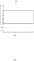
support part 40 is mounted to cross theseating hole 11. The support part is configured to support the secondary battery. Thesupport part 40 has one end connected to the fixedmodule 20 and the other end connected to thefirst gliding module 30. Also, thesupport part 40 has a size at which theentire seating hole 11 is not covered, i.e., a size at which both the sealing parts are exposed to theseating hole 11 when the secondary battery is placed on thesupport part 40. - Furthermore, a
masking block 50a is mounted on a portion of at least one (the fixed module inFIG. 2 ) of the fixedmodule 20 and thefirst gliding module 30, which comes into contact with an edge of the secondary battery. Themasking block 50a is made of a material (e.g., a silicon material, a rubber material, a synthetic material, and the like) having elasticity to prevent the sealing part from being pressed to be deformed when thefirst gliding module 30 is glided to come into contact with the sealing part after the secondary battery is seated. Also, themasking block 50a may be additionally mounted on asecond gliding module 60 and a wall part opposite to thesecond gliding module 60. Thus, when themasking blocks - In a preferred embodiment of the present invention, the
first gliding module 30 and/or the fixedmodule 20 are detachably disposed on thejig base 10, and thesupport part 40 is separably disposed on the fixedmodule 20 and thefirst gliding module 30. - Thus, since the
first gliding module 30 and thesupport part 40 are individually separable, secondary batteries having relatively large or small sizes may be alternately disposed on thejig base 10, and thefirst gliding module 30 and thesupport part 40 may be replaced with thefirst gliding module 30 and thesupport part 40, which match a size of a replaced secondary battery. That is, the secondary batteries having the various sizes may be fixed without replacing thejig base 10. - Also, in the present invention, the
wall part 15 protrudes upward along a circumference of thejig base 10, and asecond gliding module 60 that is glidable in a direction perpendicular to thefirst gliding module 30, is mounted on any one place of thewall part 15. As described above, the maskingblock 50c is detachably mounted on a portion of thesecond gliding module 60, which comes into contact with the edge of the secondary battery. When thesecond gliding module 60 moves the secondary battery, themasking block 50b is detachably mounted on the wall part coming into contact with the secondary battery. - Furthermore, the gliding of each of the
first gliding module 30 and thesecond gliding module 60 may be adjusted according to rotation directions of thehand drive bolts first gliding module 30 and thesecond gliding module 60. The hand drivebolts first gliding module 30 and thesecond gliding module 60, and thehand drive bolts first gliding module 30 and thesecond gliding module 60. - Also, the present invention may provide two embodiments according to a position of a lead of the secondary battery, i.e., whether the lead has a one-way structure (a first embodiment) in which the lead is disposed on only one side of the secondary battery or has a two-way structure (a second embodiment) in which the lead is disposed on each of both sides of the secondary battery.
-
FIG. 3 is a plan view of a jig device according to a first embodiment of the present invention,FIG. 4 is a plan and front view illustrating one side of a support part according to the first embodiment of the present invention, andFIG. 5 is a plan view of a fixed module according to the first embodiment of the present invention. - Referring to the drawings, a jig device according to the first embodiment has a structure for inspecting a secondary battery having a one-way structure in which the lead is disposed on only one side. Here, a side from which the lead protrudes is disposed to come into contact with a fixed
module 20a. - When the secondary battery is placed on a
support part 40a, afirst gliding module 30b and asecond gliding module 60 are glided to fix the secondary battery in the same manner as the above-described manner. As illustrated inFIG. 4 , thesupport part 40a according to the first embodiment comprises a mount 41a mounted on an edge portion of aseating hole 11 and asupport 42a coupled to the mount 41a with a stepped portion (a height difference) therebetween to support the secondary battery. Each of the mount 41a and thesupport 42a may have various shapes and sizes according to a shape of the secondary battery or required conditions of the inspection apparatus. - Furthermore, in the first embodiment, a measuring
device 70 for measuring a size of a lead partially protruding from the secondary battery when the secondary battery is seated adjacent to the fixedmodule 20a may be mounted (seeFIG. 3 ). Also, as illustrated inFIG. 5 , holes 22 for measuring a stepped portion (for example, a deviation in width and length due to mass-production) of the secondary battery may be additionally formed. For example, theholes 22 may be disposed at predetermined intervals. Thus, a method for measuring a degree of the deviation or a method for measuring the deviation by displaying scales on the holes may be applied according to the number ofholes 22. - Also, a clamp (see
reference numeral 21 ofFIG. 2 ) for fixing or separating thesupport part 40a may be additionally mounted on the fixedmodule 20a to easily realize the connection of thesupport part 40a. -
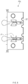
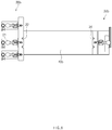
FIG. 6 is a plan view of a jig device according to a second embodiment of the present invention,FIG. 7 is a plan and front view of a support part according to the second embodiment of the present invention, andFIG. 8 is a plan view of a fixed module and a gliding module according to the second embodiment of the present invention. - Referring to the drawings, a jig device according to the second embodiment has a structure for inspecting a secondary battery having a two-way structure in which the lead is disposed on each of both sides. Here, a side from which one lead protrudes is disposed to come into contact with a fixed
module 20b. - When the secondary battery is placed on a
support part 40b, afirst gliding module 30b and asecond gliding module 60 are glided to fix the secondary battery in the same manner as the above-described manner. As illustrated inFIG. 7 , thesupport part 40b according to the second embodiment comprises amount 41b mounted on an edge portion of aseating hole 11 and asupport 42b coupled to themount 41b with a stepped portion therebetween to support the secondary battery. Each of themount 41b and thesupport 42b may have various shapes and sizes according to a shape of the secondary battery or required conditions of the inspection apparatus. - In
FIG. 7 , thesupport part 40b has shape with a width that is narrower than that of each of the secondary battery and the seating hole. Thesupport part 40b may have a shape of which a portion connected to the fixedmodule 20b and thefirst gliding module 30b has a width narrower than that of a central portion thereof. - Furthermore, in the second embodiment, measuring
devices module 20b may be respectively mounted on both sides (seeFIG. 6 ). Also, as illustrated inFIG. 8 , holes 22 and 34 for measuring a stepped portion of the secondary battery may be formed in both sides. Theholes module 20b and thefirst gliding module 30b and also formed in themount 41b of thesupport part 40b. - Also, in this embodiment, clamps 21 for fixing or separating the
support part 40b may be disposed on both sides, respectively. - The measuring
devices - According to the prevent invention comprising the above-described constituents, since the
first gliding module 30 and thesupport part 40 are individually separable, secondary batteries having various sizes may be disposed on ajig base 10, and thefirst gliding module 30 and thesupport part 40 may be replaced with thefirst gliding module 30 and thesupport part 40, which match a size of a replaced secondary battery. That is, for example, only a portion of thefirst gliding module 30 and thesupport part 40 may be replaced in a state in which thejig base 10 and the fixedmodule 20 are left in place to fix the secondary batteries having the various sizes. - Particularly, masking
blocks first gliding module 30 and thesecond gliding module 60, a pressure by which the sealing part of the secondary battery is deformed may be prevented from being applied to the sealing part. - That is, when the
first gliding module 30 and thesecond gliding module 60 push the sealing part of the secondary battery, themasking blocks masking blocks masking blocks - Also, according to the present invention, the fixed module may also be replaced, and the
second gliding module 60 that is glided in a direction crossing thefirst gliding module 30 may be additionally provided to support the secondary battery in various directions. - Also, since each of the
first gliding module 30 and thesecond gliding module 60 is glided by two or more hand drivebolts first gliding module 30 and thesecond gliding module 60. Also, since thesupport part 40 prevents the secondary battery from drooping and has the shape that is partially reduced in width, an area through which ultrasonic waves pass through the seating hole via the sealing part may increase. - Furthermore, according to the present invention, measuring
devices support part 40 may be mounted on the fixed module and the first gliding module through theclamp 31 and thus be easily separated. - While the embodiments of the present invention have been described with reference to the specific embodiments, it will be apparent to those skilled in the art that various changes and modifications may be made without departing from the scope of the following claims.
Claims (10)
- A jig device for inspecting quality of a secondary battery, which fixes the secondary battery and inspects quality of the secondary battery using ultrasonic waves, the jig device comprising:an ultrasonic inspection device;a jig base (10) having a plate shape and a seating hole (11) ;a wall part (15) protruding upward along a circumference of the jig base;a fixed module (20) mounted on the jig base at one side of the seating hole;a first gliding module (30) mounted on the jig base at a side opposite to the fixed module and glidable toward the fixed module;a second gliding module (60) that is glidable in a direction perpendicular to the first gliding module, mounted on any one position of the wall part; anda support part (40) extending across the seating hole, the support part having a first end connected to the fixed module and a second end connected to the first gliding module and on which the secondary battery is placed,wherein a masking block (50a) is mounted on one or more portions of the fixed module (20) and the first gliding module (30), which comes into contact with an edge of the secondary battery when placed on the support part, and when the masking block contacts the edge of the secondary battery, the secondary battery is fixed,wherein another masking block (50b) is detachably mounted on a portion of the second gliding module (60), which comes into contact with the edge of the secondary battery,wherein an additional masking block (50c) is detachably mounted on the wall part (15) opposite to the second gliding module (60) such that, when the secondary battery is moved by the second gliding module, the additional masking block comes into contact with the secondary battery,wherein the masking block (50a), the another masking block (50b) and the additional masking block (50c) are made of a material having elasticity to prevent the sealing part of the secondary battery from being pressed to be deformed,wherein the first gliding module is detachable from the jig base, andwherein the support part (40) has a size at which the entire seating hole (11) is not covered and is separable from the fixed module and the first gliding module.
- The jig device of claim 1, wherein the fixed module is detachable from the jig base.
- The jig device of claim 1, wherein each of the first gliding module (30) and the second gliding module (60) is adjusted according to a rotation direction of a hand drive bolt (31, 32, 33, 61, 62, 63), the hand drive bolt being screw-coupled to pass through the wall part.
- The jig device of claim 3, wherein each hand drive bolt (31, 32, 33, 61, 62, 63) is provided in a plurality so that at least two or more hand drive bolts are spaced apart from each other and are mounted on each of the first gliding module and the second gliding module.
- The jig device of claim 1, wherein the masking block is made of a silicon material.
- The jig device of any one of claims 1 to 2, wherein the support part (40) has a width that is less than a width of each of the secondary battery and the seating hole.
- The jig device of claim 6, wherein the support part (40) has a shape of which portions connected to the fixed module and the first gliding module have a width that is less than that of a central portion of the support part.
- The jig device of any one of claims 1 to 2, further comprising a measuring device mounted to the fixed module for measuring a size of a lead partially protruding from the secondary battery when the secondary battery is seated adjacent to the fixed module.
- The jig device of claim 8, further comprising another measuring device mounted to the first gliding module for measuring the size of the another lead a partially protruding from the secondary battery when the secondary battery is seated adjacent to the first gliding module.
- The jig device of any one of claims 1 to 2, wherein a clamp is mounted on each of the fixed module and the first gliding module, and the clamp of each of the fixed module and the first gliding module is connectable to the support part.
Applications Claiming Priority (2)
| Application Number | Priority Date | Filing Date | Title |
|---|---|---|---|
| KR1020170082713A KR102132754B1 (en) | 2017-06-29 | 2017-06-29 | Jig apparatus for quality test of secondary battery |
| PCT/KR2018/003624 WO2019004567A1 (en) | 2017-06-29 | 2018-03-27 | Jig device for secondary battery quality inspection |
Publications (3)
| Publication Number | Publication Date |
|---|---|
| EP3506414A1 EP3506414A1 (en) | 2019-07-03 |
| EP3506414A4 EP3506414A4 (en) | 2019-08-07 |
| EP3506414B1 true EP3506414B1 (en) | 2020-07-22 |
Family
ID=64741659
Family Applications (1)
| Application Number | Title | Priority Date | Filing Date |
|---|---|---|---|
| EP18825160.7A Active EP3506414B1 (en) | 2017-06-29 | 2018-03-27 | Jig device for inspecting quality of secondary battery |
Country Status (5)
| Country | Link |
|---|---|
| US (1) | US10957943B2 (en) |
| EP (1) | EP3506414B1 (en) |
| KR (1) | KR102132754B1 (en) |
| CN (1) | CN109845022B (en) |
| WO (1) | WO2019004567A1 (en) |
Families Citing this family (7)
| Publication number | Priority date | Publication date | Assignee | Title |
|---|---|---|---|---|
| CN110193665A (en) * | 2019-06-19 | 2019-09-03 | 广东风华新能源股份有限公司 | A kind of fixture for laser welding of lithium battery |
| CN112247437A (en) * | 2020-01-20 | 2021-01-22 | 蜂巢能源科技有限公司 | Clamp for welding battery cell and method for welding battery cell |
| KR20230076705A (en) | 2021-11-24 | 2023-05-31 | 주식회사 원익피앤이 | Apparatus and method for controlling sealing quality of secondary battery case |
| KR20240013367A (en) | 2022-07-22 | 2024-01-30 | 주식회사 엘지에너지솔루션 | Fixing jig of cylinder type secondary battery and safety evaluation method |
| KR102547866B1 (en) * | 2023-03-10 | 2023-06-26 | 주식회사 제이디 | Jig and device for inspecting sealing surface of pouch-type secondary battery for contact heating |
| KR102580372B1 (en) * | 2023-03-10 | 2023-09-19 | 주식회사 제이디 | Jig and device for inspecting sealing surface of pouch-type secondary battery for laser heating |
| CN116718317B (en) * | 2023-08-09 | 2024-02-20 | 江苏常丰精密科技有限公司 | Power battery shell leakage detection device |
Family Cites Families (21)
| Publication number | Priority date | Publication date | Assignee | Title |
|---|---|---|---|---|
| GB1193501A (en) | 1967-02-02 | 1970-06-03 | Watson W & Sons Ltd | Improvements in or relating to Positioning Apparatus |
| JP4666712B2 (en) * | 2000-02-22 | 2011-04-06 | パナソニック株式会社 | Battery short-circuit inspection method |
| KR101031538B1 (en) | 2009-04-13 | 2011-04-27 | 주식회사 피앤이솔루션 | A construction of contact pin in lithium polymer battery jig |
| JP5566719B2 (en) * | 2010-02-15 | 2014-08-06 | 株式会社東芝 | Secondary battery device |
| US8680869B2 (en) * | 2010-02-16 | 2014-03-25 | Blackberry Limited | AC charging contact mechanism |
| WO2011126161A1 (en) | 2010-04-07 | 2011-10-13 | 주식회사 이아이지 | Secondary battery module |
| CN202444010U (en) | 2011-12-22 | 2012-09-19 | 四川大学 | Battery box of external charger of cell phone |
| KR101534515B1 (en) | 2013-05-14 | 2015-07-07 | (주)에이치엔티 | Two-way battery jig |
| JP6069109B2 (en) | 2013-06-12 | 2017-01-25 | 浜松ホトニクス株式会社 | Sample holding member insertion / extraction mechanism and image acquisition device |
| KR101551534B1 (en) * | 2013-09-30 | 2015-09-08 | 주식회사 엘지화학 | Test jig |
| KR101798688B1 (en) * | 2013-10-21 | 2017-11-16 | 주식회사 엘지화학 | Function test jig of battery cell |
| KR101772729B1 (en) * | 2013-10-30 | 2017-08-29 | 주식회사 엘지화학 | Jig device and processing method of using thereof |
| KR101713182B1 (en) * | 2013-10-31 | 2017-03-07 | 주식회사 엘지화학 | Zig for fixing secondary battery and apparatus for charging and discharging secondary battery including the same |
| JP2015153731A (en) | 2014-02-19 | 2015-08-24 | 株式会社京浜理化工業 | Battery cell for test |
| CN104049115B (en) | 2014-06-16 | 2017-02-01 | 深圳市瑞能实业股份有限公司 | Polymer soft package battery detecting clamp |
| KR102091826B1 (en) * | 2014-06-17 | 2020-03-20 | 에스케이이노베이션 주식회사 | Tray for loading battery cell |
| KR20160015751A (en) * | 2014-07-31 | 2016-02-15 | 에스케이이노베이션 주식회사 | Structure for fixing dimension of battery cell and parallel connecting structure between battery cells using the same |
| KR101790639B1 (en) * | 2014-12-15 | 2017-10-26 | 주식회사 엘지화학 | Fixing Jig Used in Charging and Discharging or Test of Secondary Battery |
| KR101717838B1 (en) | 2015-04-07 | 2017-03-17 | 이동석 | Inspection apparatus for battery |
| KR102039526B1 (en) | 2016-07-12 | 2019-11-01 | 주식회사 엘지화학 | Device and method for inspection of sealing performance of pouch type secondary battery |
| US10629966B2 (en) * | 2016-11-02 | 2020-04-21 | Feasible, Inc. | Modular, adaptable holders for sensors and battery cells for physical analysis |
-
2017
- 2017-06-29 KR KR1020170082713A patent/KR102132754B1/en active IP Right Grant
-
2018
- 2018-03-27 WO PCT/KR2018/003624 patent/WO2019004567A1/en unknown
- 2018-03-27 US US16/337,313 patent/US10957943B2/en active Active
- 2018-03-27 CN CN201880003868.3A patent/CN109845022B/en active Active
- 2018-03-27 EP EP18825160.7A patent/EP3506414B1/en active Active
Non-Patent Citations (1)
| Title |
|---|
| None * |
Also Published As
| Publication number | Publication date |
|---|---|
| KR20190002180A (en) | 2019-01-08 |
| EP3506414A1 (en) | 2019-07-03 |
| US20200036054A1 (en) | 2020-01-30 |
| WO2019004567A1 (en) | 2019-01-03 |
| US10957943B2 (en) | 2021-03-23 |
| CN109845022B (en) | 2021-11-26 |
| EP3506414A4 (en) | 2019-08-07 |
| KR102132754B1 (en) | 2020-07-13 |
| CN109845022A (en) | 2019-06-04 |
Similar Documents
| Publication | Publication Date | Title |
|---|---|---|
| EP3506414B1 (en) | Jig device for inspecting quality of secondary battery | |
| US11522258B2 (en) | Electrolyte removing device, apparatus and method for manufacturing secondary battery comprising the same, and secondary battery | |
| US20190094003A1 (en) | Secondary battery evaluation apparatus | |
| JP6115683B2 (en) | Battery cell pressurizer | |
| KR102291536B1 (en) | Apparatus and method for testing a battery pack | |
| US20190207183A1 (en) | Battery cell degassing apparatus | |
| TWI653456B (en) | Battery cell formation device and probe support structure thereof | |
| US20190207241A1 (en) | Battery cell degassing apparatus | |
| CN108604655B (en) | Belt for battery module, battery module including belt, and jig for compressing belt | |
| KR20200056531A (en) | Manufacturing apparatus for top cap assambly of rechargeable battery and manufacturing method using the same | |
| KR101826894B1 (en) | Electrode assembly and apparatus for manufacturing the same | |
| KR101839566B1 (en) | Apparatus of Attaching Sheets to Secondary Battery Pack | |
| US11830987B2 (en) | Electrolyte detection device and secondary battery transfer facility comprising the same | |
| KR102326441B1 (en) | Sealing device and sealing method of pouch for secondary battery | |
| KR101630214B1 (en) | Clamping device for polymer ce11 battery | |
| KR101255353B1 (en) | Manufacturing method for battery | |
| KR20060002568A (en) | Preparation method and an apparatus of electrode tab attachment for secondary battery | |
| KR20130110281A (en) | Thickness measuring device with novel structure | |
| JP5758751B2 (en) | Secondary battery evaluation jig and secondary battery evaluation method | |
| KR102111454B1 (en) | Apparatus for of measuring pouch depth for rechargeable battery and method of measuring using the same | |
| KR101863095B1 (en) | Manufacturing apparatus for a battery pack | |
| KR101100033B1 (en) | Heat fusion block for heat fusion film of electrode tab | |
| CN216631646U (en) | Battery pole piece automatic weighing device and lithium ion battery test equipment | |
| CN216485426U (en) | Test tool | |
| CN213752770U (en) | Clamp for installing lithium battery into metal frame |
Legal Events
| Date | Code | Title | Description |
|---|---|---|---|
| STAA | Information on the status of an ep patent application or granted ep patent |
Free format text: STATUS: THE INTERNATIONAL PUBLICATION HAS BEEN MADE |
|
| PUAI | Public reference made under article 153(3) epc to a published international application that has entered the european phase |
Free format text: ORIGINAL CODE: 0009012 |
|
| STAA | Information on the status of an ep patent application or granted ep patent |
Free format text: STATUS: REQUEST FOR EXAMINATION WAS MADE |
|
| 17P | Request for examination filed |
Effective date: 20190328 |
|
| AK | Designated contracting states |
Kind code of ref document: A1 Designated state(s): AL AT BE BG CH CY CZ DE DK EE ES FI FR GB GR HR HU IE IS IT LI LT LU LV MC MK MT NL NO PL PT RO RS SE SI SK SM TR |
|
| AX | Request for extension of the european patent |
Extension state: BA ME |
|
| A4 | Supplementary search report drawn up and despatched |
Effective date: 20190709 |
|
| RIC1 | Information provided on ipc code assigned before grant |
Ipc: H01M 10/42 20060101AFI20190703BHEP |
|
| GRAP | Despatch of communication of intention to grant a patent |
Free format text: ORIGINAL CODE: EPIDOSNIGR1 |
|
| STAA | Information on the status of an ep patent application or granted ep patent |
Free format text: STATUS: GRANT OF PATENT IS INTENDED |
|
| DAV | Request for validation of the european patent (deleted) | ||
| DAX | Request for extension of the european patent (deleted) | ||
| INTG | Intention to grant announced |
Effective date: 20200309 |
|
| GRAS | Grant fee paid |
Free format text: ORIGINAL CODE: EPIDOSNIGR3 |
|
| GRAA | (expected) grant |
Free format text: ORIGINAL CODE: 0009210 |
|
| STAA | Information on the status of an ep patent application or granted ep patent |
Free format text: STATUS: THE PATENT HAS BEEN GRANTED |
|
| AK | Designated contracting states |
Kind code of ref document: B1 Designated state(s): AL AT BE BG CH CY CZ DE DK EE ES FI FR GB GR HR HU IE IS IT LI LT LU LV MC MK MT NL NO PL PT RO RS SE SI SK SM TR |
|
| REG | Reference to a national code |
Ref country code: GB Ref legal event code: FG4D |
|
| REG | Reference to a national code |
Ref country code: CH Ref legal event code: EP |
|
| REG | Reference to a national code |
Ref country code: DE Ref legal event code: R096 Ref document number: 602018006290 Country of ref document: DE |
|
| REG | Reference to a national code |
Ref country code: AT Ref legal event code: REF Ref document number: 1294252 Country of ref document: AT Kind code of ref document: T Effective date: 20200815 |
|
| REG | Reference to a national code |
Ref country code: IE Ref legal event code: FG4D |
|
| REG | Reference to a national code |
Ref country code: LT Ref legal event code: MG4D |
|
| REG | Reference to a national code |
Ref country code: AT Ref legal event code: MK05 Ref document number: 1294252 Country of ref document: AT Kind code of ref document: T Effective date: 20200722 |
|
| PG25 | Lapsed in a contracting state [announced via postgrant information from national office to epo] |
Ref country code: GR Free format text: LAPSE BECAUSE OF FAILURE TO SUBMIT A TRANSLATION OF THE DESCRIPTION OR TO PAY THE FEE WITHIN THE PRESCRIBED TIME-LIMIT Effective date: 20201023 Ref country code: NO Free format text: LAPSE BECAUSE OF FAILURE TO SUBMIT A TRANSLATION OF THE DESCRIPTION OR TO PAY THE FEE WITHIN THE PRESCRIBED TIME-LIMIT Effective date: 20201022 Ref country code: FI Free format text: LAPSE BECAUSE OF FAILURE TO SUBMIT A TRANSLATION OF THE DESCRIPTION OR TO PAY THE FEE WITHIN THE PRESCRIBED TIME-LIMIT Effective date: 20200722 Ref country code: LT Free format text: LAPSE BECAUSE OF FAILURE TO SUBMIT A TRANSLATION OF THE DESCRIPTION OR TO PAY THE FEE WITHIN THE PRESCRIBED TIME-LIMIT Effective date: 20200722 Ref country code: PT Free format text: LAPSE BECAUSE OF FAILURE TO SUBMIT A TRANSLATION OF THE DESCRIPTION OR TO PAY THE FEE WITHIN THE PRESCRIBED TIME-LIMIT Effective date: 20201123 Ref country code: HR Free format text: LAPSE BECAUSE OF FAILURE TO SUBMIT A TRANSLATION OF THE DESCRIPTION OR TO PAY THE FEE WITHIN THE PRESCRIBED TIME-LIMIT Effective date: 20200722 Ref country code: AT Free format text: LAPSE BECAUSE OF FAILURE TO SUBMIT A TRANSLATION OF THE DESCRIPTION OR TO PAY THE FEE WITHIN THE PRESCRIBED TIME-LIMIT Effective date: 20200722 Ref country code: BG Free format text: LAPSE BECAUSE OF FAILURE TO SUBMIT A TRANSLATION OF THE DESCRIPTION OR TO PAY THE FEE WITHIN THE PRESCRIBED TIME-LIMIT Effective date: 20201022 Ref country code: SE Free format text: LAPSE BECAUSE OF FAILURE TO SUBMIT A TRANSLATION OF THE DESCRIPTION OR TO PAY THE FEE WITHIN THE PRESCRIBED TIME-LIMIT Effective date: 20200722 Ref country code: ES Free format text: LAPSE BECAUSE OF FAILURE TO SUBMIT A TRANSLATION OF THE DESCRIPTION OR TO PAY THE FEE WITHIN THE PRESCRIBED TIME-LIMIT Effective date: 20200722 |
|
| PG25 | Lapsed in a contracting state [announced via postgrant information from national office to epo] |
Ref country code: PL Free format text: LAPSE BECAUSE OF FAILURE TO SUBMIT A TRANSLATION OF THE DESCRIPTION OR TO PAY THE FEE WITHIN THE PRESCRIBED TIME-LIMIT Effective date: 20200722 Ref country code: RS Free format text: LAPSE BECAUSE OF FAILURE TO SUBMIT A TRANSLATION OF THE DESCRIPTION OR TO PAY THE FEE WITHIN THE PRESCRIBED TIME-LIMIT Effective date: 20200722 Ref country code: LV Free format text: LAPSE BECAUSE OF FAILURE TO SUBMIT A TRANSLATION OF THE DESCRIPTION OR TO PAY THE FEE WITHIN THE PRESCRIBED TIME-LIMIT Effective date: 20200722 Ref country code: IS Free format text: LAPSE BECAUSE OF FAILURE TO SUBMIT A TRANSLATION OF THE DESCRIPTION OR TO PAY THE FEE WITHIN THE PRESCRIBED TIME-LIMIT Effective date: 20201122 |
|
| PG25 | Lapsed in a contracting state [announced via postgrant information from national office to epo] |
Ref country code: NL Free format text: LAPSE BECAUSE OF FAILURE TO SUBMIT A TRANSLATION OF THE DESCRIPTION OR TO PAY THE FEE WITHIN THE PRESCRIBED TIME-LIMIT Effective date: 20200722 |
|
| REG | Reference to a national code |
Ref country code: DE Ref legal event code: R097 Ref document number: 602018006290 Country of ref document: DE |
|
| PG25 | Lapsed in a contracting state [announced via postgrant information from national office to epo] |
Ref country code: SM Free format text: LAPSE BECAUSE OF FAILURE TO SUBMIT A TRANSLATION OF THE DESCRIPTION OR TO PAY THE FEE WITHIN THE PRESCRIBED TIME-LIMIT Effective date: 20200722 Ref country code: IT Free format text: LAPSE BECAUSE OF FAILURE TO SUBMIT A TRANSLATION OF THE DESCRIPTION OR TO PAY THE FEE WITHIN THE PRESCRIBED TIME-LIMIT Effective date: 20200722 Ref country code: EE Free format text: LAPSE BECAUSE OF FAILURE TO SUBMIT A TRANSLATION OF THE DESCRIPTION OR TO PAY THE FEE WITHIN THE PRESCRIBED TIME-LIMIT Effective date: 20200722 Ref country code: RO Free format text: LAPSE BECAUSE OF FAILURE TO SUBMIT A TRANSLATION OF THE DESCRIPTION OR TO PAY THE FEE WITHIN THE PRESCRIBED TIME-LIMIT Effective date: 20200722 Ref country code: DK Free format text: LAPSE BECAUSE OF FAILURE TO SUBMIT A TRANSLATION OF THE DESCRIPTION OR TO PAY THE FEE WITHIN THE PRESCRIBED TIME-LIMIT Effective date: 20200722 Ref country code: CZ Free format text: LAPSE BECAUSE OF FAILURE TO SUBMIT A TRANSLATION OF THE DESCRIPTION OR TO PAY THE FEE WITHIN THE PRESCRIBED TIME-LIMIT Effective date: 20200722 |
|
| PLBE | No opposition filed within time limit |
Free format text: ORIGINAL CODE: 0009261 |
|
| STAA | Information on the status of an ep patent application or granted ep patent |
Free format text: STATUS: NO OPPOSITION FILED WITHIN TIME LIMIT |
|
| PG25 | Lapsed in a contracting state [announced via postgrant information from national office to epo] |
Ref country code: AL Free format text: LAPSE BECAUSE OF FAILURE TO SUBMIT A TRANSLATION OF THE DESCRIPTION OR TO PAY THE FEE WITHIN THE PRESCRIBED TIME-LIMIT Effective date: 20200722 |
|
| 26N | No opposition filed |
Effective date: 20210423 |
|
| PG25 | Lapsed in a contracting state [announced via postgrant information from national office to epo] |
Ref country code: SK Free format text: LAPSE BECAUSE OF FAILURE TO SUBMIT A TRANSLATION OF THE DESCRIPTION OR TO PAY THE FEE WITHIN THE PRESCRIBED TIME-LIMIT Effective date: 20200722 |
|
| PG25 | Lapsed in a contracting state [announced via postgrant information from national office to epo] |
Ref country code: SI Free format text: LAPSE BECAUSE OF FAILURE TO SUBMIT A TRANSLATION OF THE DESCRIPTION OR TO PAY THE FEE WITHIN THE PRESCRIBED TIME-LIMIT Effective date: 20200722 |
|
| REG | Reference to a national code |
Ref country code: NL Ref legal event code: MP Effective date: 20200722 |
|
| PG25 | Lapsed in a contracting state [announced via postgrant information from national office to epo] |
Ref country code: MC Free format text: LAPSE BECAUSE OF FAILURE TO SUBMIT A TRANSLATION OF THE DESCRIPTION OR TO PAY THE FEE WITHIN THE PRESCRIBED TIME-LIMIT Effective date: 20200722 |
|
| REG | Reference to a national code |
Ref country code: CH Ref legal event code: PL |
|
| REG | Reference to a national code |
Ref country code: BE Ref legal event code: MM Effective date: 20210331 |
|
| PG25 | Lapsed in a contracting state [announced via postgrant information from national office to epo] |
Ref country code: IE Free format text: LAPSE BECAUSE OF NON-PAYMENT OF DUE FEES Effective date: 20210327 Ref country code: LU Free format text: LAPSE BECAUSE OF NON-PAYMENT OF DUE FEES Effective date: 20210327 Ref country code: LI Free format text: LAPSE BECAUSE OF NON-PAYMENT OF DUE FEES Effective date: 20210331 Ref country code: CH Free format text: LAPSE BECAUSE OF NON-PAYMENT OF DUE FEES Effective date: 20210331 |
|
| PG25 | Lapsed in a contracting state [announced via postgrant information from national office to epo] |
Ref country code: BE Free format text: LAPSE BECAUSE OF NON-PAYMENT OF DUE FEES Effective date: 20210331 |
|
| PGFP | Annual fee paid to national office [announced via postgrant information from national office to epo] |
Ref country code: FR Payment date: 20230221 Year of fee payment: 6 |
|
| REG | Reference to a national code |
Ref country code: DE Ref legal event code: R081 Ref document number: 602018006290 Country of ref document: DE Owner name: LG ENERGY SOLUTION, LTD., KR Free format text: FORMER OWNER: LG CHEM. LTD., SEOUL, KR |
|
| PGFP | Annual fee paid to national office [announced via postgrant information from national office to epo] |
Ref country code: GB Payment date: 20230220 Year of fee payment: 6 Ref country code: DE Payment date: 20230220 Year of fee payment: 6 |
|
| P01 | Opt-out of the competence of the unified patent court (upc) registered |
Effective date: 20230512 |
|
| PG25 | Lapsed in a contracting state [announced via postgrant information from national office to epo] |
Ref country code: CY Free format text: LAPSE BECAUSE OF FAILURE TO SUBMIT A TRANSLATION OF THE DESCRIPTION OR TO PAY THE FEE WITHIN THE PRESCRIBED TIME-LIMIT Effective date: 20200722 |
|
| PG25 | Lapsed in a contracting state [announced via postgrant information from national office to epo] |
Ref country code: HU Free format text: LAPSE BECAUSE OF FAILURE TO SUBMIT A TRANSLATION OF THE DESCRIPTION OR TO PAY THE FEE WITHIN THE PRESCRIBED TIME-LIMIT; INVALID AB INITIO Effective date: 20180327 |
|
| REG | Reference to a national code |
Ref country code: GB Ref legal event code: 732E Free format text: REGISTERED BETWEEN 20230824 AND 20230831 |