EP3506322A1 - Flat cable, rotary connector in which same is used, and method for manufacturing flat cable - Google Patents
Flat cable, rotary connector in which same is used, and method for manufacturing flat cable Download PDFInfo
- Publication number
- EP3506322A1 EP3506322A1 EP17843279.5A EP17843279A EP3506322A1 EP 3506322 A1 EP3506322 A1 EP 3506322A1 EP 17843279 A EP17843279 A EP 17843279A EP 3506322 A1 EP3506322 A1 EP 3506322A1
- Authority
- EP
- European Patent Office
- Prior art keywords
- layer
- flat cable
- melting point
- conductors
- polyphenylene sulfide
- Prior art date
- Legal status (The legal status is an assumption and is not a legal conclusion. Google has not performed a legal analysis and makes no representation as to the accuracy of the status listed.)
- Pending
Links
- 238000004519 manufacturing process Methods 0.000 title claims description 37
- 238000000034 method Methods 0.000 title claims description 13
- 229920005989 resin Polymers 0.000 claims abstract description 191
- 239000011347 resin Substances 0.000 claims abstract description 191
- 238000002844 melting Methods 0.000 claims abstract description 105
- 230000008018 melting Effects 0.000 claims abstract description 105
- 239000004020 conductor Substances 0.000 claims abstract description 102
- 239000004734 Polyphenylene sulfide Substances 0.000 claims abstract description 97
- 229920000069 polyphenylene sulfide Polymers 0.000 claims abstract description 97
- 239000010410 layer Substances 0.000 claims description 211
- 230000006835 compression Effects 0.000 claims description 32
- 238000007906 compression Methods 0.000 claims description 32
- 239000013307 optical fiber Substances 0.000 claims description 27
- 238000010438 heat treatment Methods 0.000 claims description 26
- 238000005452 bending Methods 0.000 claims description 21
- 239000000463 material Substances 0.000 claims description 20
- 230000004927 fusion Effects 0.000 claims description 12
- 239000000314 lubricant Substances 0.000 claims description 11
- 239000011241 protective layer Substances 0.000 claims description 11
- 238000004132 cross linking Methods 0.000 claims description 9
- 239000004215 Carbon black (E152) Substances 0.000 claims description 6
- 229930195733 hydrocarbon Natural products 0.000 claims description 6
- 150000002430 hydrocarbons Chemical class 0.000 claims description 6
- 230000001681 protective effect Effects 0.000 claims description 3
- 239000007888 film coating Substances 0.000 claims 2
- 238000009501 film coating Methods 0.000 claims 2
- 239000011248 coating agent Substances 0.000 abstract description 6
- 238000000576 coating method Methods 0.000 abstract description 6
- 230000000052 comparative effect Effects 0.000 description 30
- 238000012360 testing method Methods 0.000 description 30
- RYGMFSIKBFXOCR-UHFFFAOYSA-N Copper Chemical compound [Cu] RYGMFSIKBFXOCR-UHFFFAOYSA-N 0.000 description 25
- 239000011889 copper foil Substances 0.000 description 25
- 229920000728 polyester Polymers 0.000 description 17
- 239000000853 adhesive Substances 0.000 description 13
- 230000001070 adhesive effect Effects 0.000 description 13
- 238000001125 extrusion Methods 0.000 description 10
- 238000010586 diagram Methods 0.000 description 9
- 238000004804 winding Methods 0.000 description 8
- 238000011156 evaluation Methods 0.000 description 7
- RNFJDJUURJAICM-UHFFFAOYSA-N 2,2,4,4,6,6-hexaphenoxy-1,3,5-triaza-2$l^{5},4$l^{5},6$l^{5}-triphosphacyclohexa-1,3,5-triene Chemical compound N=1P(OC=2C=CC=CC=2)(OC=2C=CC=CC=2)=NP(OC=2C=CC=CC=2)(OC=2C=CC=CC=2)=NP=1(OC=1C=CC=CC=1)OC1=CC=CC=C1 RNFJDJUURJAICM-UHFFFAOYSA-N 0.000 description 6
- 239000003063 flame retardant Substances 0.000 description 6
- 230000002159 abnormal effect Effects 0.000 description 5
- 230000007547 defect Effects 0.000 description 5
- 150000001925 cycloalkenes Chemical class 0.000 description 4
- 239000000203 mixture Substances 0.000 description 4
- 230000000694 effects Effects 0.000 description 3
- 230000006870 function Effects 0.000 description 3
- 230000009477 glass transition Effects 0.000 description 3
- 238000009998 heat setting Methods 0.000 description 3
- 238000007731 hot pressing Methods 0.000 description 3
- 239000000155 melt Substances 0.000 description 3
- 230000008569 process Effects 0.000 description 3
- 239000004593 Epoxy Substances 0.000 description 2
- YCKRFDGAMUMZLT-UHFFFAOYSA-N Fluorine atom Chemical compound [F] YCKRFDGAMUMZLT-UHFFFAOYSA-N 0.000 description 2
- XAGFODPZIPBFFR-UHFFFAOYSA-N aluminium Chemical compound [Al] XAGFODPZIPBFFR-UHFFFAOYSA-N 0.000 description 2
- 229910052782 aluminium Inorganic materials 0.000 description 2
- 230000002950 deficient Effects 0.000 description 2
- 238000013461 design Methods 0.000 description 2
- 238000001035 drying Methods 0.000 description 2
- 238000010894 electron beam technology Methods 0.000 description 2
- 229910052731 fluorine Inorganic materials 0.000 description 2
- 239000011737 fluorine Substances 0.000 description 2
- 239000011888 foil Substances 0.000 description 2
- 229920003229 poly(methyl methacrylate) Polymers 0.000 description 2
- 229920001225 polyester resin Polymers 0.000 description 2
- 239000004926 polymethyl methacrylate Substances 0.000 description 2
- 239000002904 solvent Substances 0.000 description 2
- 239000000126 substance Substances 0.000 description 2
- 239000004642 Polyimide Substances 0.000 description 1
- BZHJMEDXRYGGRV-UHFFFAOYSA-N Vinyl chloride Chemical compound ClC=C BZHJMEDXRYGGRV-UHFFFAOYSA-N 0.000 description 1
- 230000004308 accommodation Effects 0.000 description 1
- 230000003213 activating effect Effects 0.000 description 1
- 230000008859 change Effects 0.000 description 1
- 238000010382 chemical cross-linking Methods 0.000 description 1
- 239000003795 chemical substances by application Substances 0.000 description 1
- 238000002485 combustion reaction Methods 0.000 description 1
- 239000000470 constituent Substances 0.000 description 1
- 239000003431 cross linking reagent Substances 0.000 description 1
- 230000003247 decreasing effect Effects 0.000 description 1
- 230000007850 degeneration Effects 0.000 description 1
- 238000005516 engineering process Methods 0.000 description 1
- 238000005530 etching Methods 0.000 description 1
- 239000000835 fiber Substances 0.000 description 1
- 230000017525 heat dissipation Effects 0.000 description 1
- 238000010348 incorporation Methods 0.000 description 1
- 239000007788 liquid Substances 0.000 description 1
- 238000012986 modification Methods 0.000 description 1
- 230000004048 modification Effects 0.000 description 1
- 230000003287 optical effect Effects 0.000 description 1
- 229920000515 polycarbonate Polymers 0.000 description 1
- 239000004417 polycarbonate Substances 0.000 description 1
- 229920001601 polyetherimide Polymers 0.000 description 1
- 229920001721 polyimide Polymers 0.000 description 1
- 229920001296 polysiloxane Polymers 0.000 description 1
- 238000002360 preparation method Methods 0.000 description 1
- 230000002265 prevention Effects 0.000 description 1
- 238000012545 processing Methods 0.000 description 1
- 239000002994 raw material Substances 0.000 description 1
- 230000002829 reductive effect Effects 0.000 description 1
- 230000002441 reversible effect Effects 0.000 description 1
- 239000002356 single layer Substances 0.000 description 1
- 238000005549 size reduction Methods 0.000 description 1
- 230000003068 static effect Effects 0.000 description 1
- 230000008961 swelling Effects 0.000 description 1
Images

Classifications
-
- H—ELECTRICITY
- H01—ELECTRIC ELEMENTS
- H01B—CABLES; CONDUCTORS; INSULATORS; SELECTION OF MATERIALS FOR THEIR CONDUCTIVE, INSULATING OR DIELECTRIC PROPERTIES
- H01B7/00—Insulated conductors or cables characterised by their form
- H01B7/08—Flat or ribbon cables
- H01B7/0838—Parallel wires, sandwiched between two insulating layers
-
- C—CHEMISTRY; METALLURGY
- C08—ORGANIC MACROMOLECULAR COMPOUNDS; THEIR PREPARATION OR CHEMICAL WORKING-UP; COMPOSITIONS BASED THEREON
- C08L—COMPOSITIONS OF MACROMOLECULAR COMPOUNDS
- C08L81/00—Compositions of macromolecular compounds obtained by reactions forming in the main chain of the macromolecule a linkage containing sulfur with or without nitrogen, oxygen or carbon only; Compositions of polysulfones; Compositions of derivatives of such polymers
- C08L81/02—Polythioethers; Polythioether-ethers
-
- G—PHYSICS
- G02—OPTICS
- G02B—OPTICAL ELEMENTS, SYSTEMS OR APPARATUS
- G02B1/00—Optical elements characterised by the material of which they are made; Optical coatings for optical elements
- G02B1/10—Optical coatings produced by application to, or surface treatment of, optical elements
- G02B1/14—Protective coatings, e.g. hard coatings
-
- G—PHYSICS
- G02—OPTICS
- G02B—OPTICAL ELEMENTS, SYSTEMS OR APPARATUS
- G02B6/00—Light guides; Structural details of arrangements comprising light guides and other optical elements, e.g. couplings
- G02B6/44—Mechanical structures for providing tensile strength and external protection for fibres, e.g. optical transmission cables
-
- G—PHYSICS
- G02—OPTICS
- G02B—OPTICAL ELEMENTS, SYSTEMS OR APPARATUS
- G02B6/00—Light guides; Structural details of arrangements comprising light guides and other optical elements, e.g. couplings
- G02B6/44—Mechanical structures for providing tensile strength and external protection for fibres, e.g. optical transmission cables
- G02B6/4401—Optical cables
- G02B6/4429—Means specially adapted for strengthening or protecting the cables
- G02B6/4436—Heat resistant
-
- G—PHYSICS
- G02—OPTICS
- G02B—OPTICAL ELEMENTS, SYSTEMS OR APPARATUS
- G02B6/00—Light guides; Structural details of arrangements comprising light guides and other optical elements, e.g. couplings
- G02B6/44—Mechanical structures for providing tensile strength and external protection for fibres, e.g. optical transmission cables
- G02B6/4479—Manufacturing methods of optical cables
- G02B6/448—Ribbon cables
-
- G—PHYSICS
- G02—OPTICS
- G02B—OPTICAL ELEMENTS, SYSTEMS OR APPARATUS
- G02B6/00—Light guides; Structural details of arrangements comprising light guides and other optical elements, e.g. couplings
- G02B6/44—Mechanical structures for providing tensile strength and external protection for fibres, e.g. optical transmission cables
- G02B6/4479—Manufacturing methods of optical cables
- G02B6/4486—Protective covering
-
- H—ELECTRICITY
- H01—ELECTRIC ELEMENTS
- H01B—CABLES; CONDUCTORS; INSULATORS; SELECTION OF MATERIALS FOR THEIR CONDUCTIVE, INSULATING OR DIELECTRIC PROPERTIES
- H01B13/00—Apparatus or processes specially adapted for manufacturing conductors or cables
-
- H—ELECTRICITY
- H01—ELECTRIC ELEMENTS
- H01B—CABLES; CONDUCTORS; INSULATORS; SELECTION OF MATERIALS FOR THEIR CONDUCTIVE, INSULATING OR DIELECTRIC PROPERTIES
- H01B13/00—Apparatus or processes specially adapted for manufacturing conductors or cables
- H01B13/0013—Apparatus or processes specially adapted for manufacturing conductors or cables for embedding wires in plastic layers
-
- H—ELECTRICITY
- H01—ELECTRIC ELEMENTS
- H01B—CABLES; CONDUCTORS; INSULATORS; SELECTION OF MATERIALS FOR THEIR CONDUCTIVE, INSULATING OR DIELECTRIC PROPERTIES
- H01B13/00—Apparatus or processes specially adapted for manufacturing conductors or cables
- H01B13/0016—Apparatus or processes specially adapted for manufacturing conductors or cables for heat treatment
-
- H—ELECTRICITY
- H01—ELECTRIC ELEMENTS
- H01B—CABLES; CONDUCTORS; INSULATORS; SELECTION OF MATERIALS FOR THEIR CONDUCTIVE, INSULATING OR DIELECTRIC PROPERTIES
- H01B13/00—Apparatus or processes specially adapted for manufacturing conductors or cables
- H01B13/06—Insulating conductors or cables
-
- H—ELECTRICITY
- H01—ELECTRIC ELEMENTS
- H01B—CABLES; CONDUCTORS; INSULATORS; SELECTION OF MATERIALS FOR THEIR CONDUCTIVE, INSULATING OR DIELECTRIC PROPERTIES
- H01B3/00—Insulators or insulating bodies characterised by the insulating materials; Selection of materials for their insulating or dielectric properties
- H01B3/18—Insulators or insulating bodies characterised by the insulating materials; Selection of materials for their insulating or dielectric properties mainly consisting of organic substances
- H01B3/30—Insulators or insulating bodies characterised by the insulating materials; Selection of materials for their insulating or dielectric properties mainly consisting of organic substances plastics; resins; waxes
- H01B3/301—Macromolecular compounds obtained by reactions forming a linkage containing sulfur with or without nitrogen, oxygen or carbon in the main chain of the macromolecule, not provided for in group H01B3/302
-
- H—ELECTRICITY
- H01—ELECTRIC ELEMENTS
- H01B—CABLES; CONDUCTORS; INSULATORS; SELECTION OF MATERIALS FOR THEIR CONDUCTIVE, INSULATING OR DIELECTRIC PROPERTIES
- H01B7/00—Insulated conductors or cables characterised by their form
- H01B7/02—Disposition of insulation
-
- H—ELECTRICITY
- H01—ELECTRIC ELEMENTS
- H01B—CABLES; CONDUCTORS; INSULATORS; SELECTION OF MATERIALS FOR THEIR CONDUCTIVE, INSULATING OR DIELECTRIC PROPERTIES
- H01B7/00—Insulated conductors or cables characterised by their form
- H01B7/02—Disposition of insulation
- H01B7/0208—Cables with several layers of insulating material
- H01B7/0216—Two layers
-
- H—ELECTRICITY
- H01—ELECTRIC ELEMENTS
- H01B—CABLES; CONDUCTORS; INSULATORS; SELECTION OF MATERIALS FOR THEIR CONDUCTIVE, INSULATING OR DIELECTRIC PROPERTIES
- H01B7/00—Insulated conductors or cables characterised by their form
- H01B7/08—Flat or ribbon cables
-
- H—ELECTRICITY
- H01—ELECTRIC ELEMENTS
- H01B—CABLES; CONDUCTORS; INSULATORS; SELECTION OF MATERIALS FOR THEIR CONDUCTIVE, INSULATING OR DIELECTRIC PROPERTIES
- H01B7/00—Insulated conductors or cables characterised by their form
- H01B7/08—Flat or ribbon cables
- H01B7/0807—Twin conductor or cable
-
- H—ELECTRICITY
- H01—ELECTRIC ELEMENTS
- H01R—ELECTRICALLY-CONDUCTIVE CONNECTIONS; STRUCTURAL ASSOCIATIONS OF A PLURALITY OF MUTUALLY-INSULATED ELECTRICAL CONNECTING ELEMENTS; COUPLING DEVICES; CURRENT COLLECTORS
- H01R35/00—Flexible or turnable line connectors, i.e. the rotation angle being limited
- H01R35/04—Turnable line connectors with limited rotation angle with frictional contact members
-
- H—ELECTRICITY
- H01—ELECTRIC ELEMENTS
- H01B—CABLES; CONDUCTORS; INSULATORS; SELECTION OF MATERIALS FOR THEIR CONDUCTIVE, INSULATING OR DIELECTRIC PROPERTIES
- H01B13/00—Apparatus or processes specially adapted for manufacturing conductors or cables
- H01B13/0003—Apparatus or processes specially adapted for manufacturing conductors or cables for feeding conductors or cables
-
- H—ELECTRICITY
- H01—ELECTRIC ELEMENTS
- H01R—ELECTRICALLY-CONDUCTIVE CONNECTIONS; STRUCTURAL ASSOCIATIONS OF A PLURALITY OF MUTUALLY-INSULATED ELECTRICAL CONNECTING ELEMENTS; COUPLING DEVICES; CURRENT COLLECTORS
- H01R2201/00—Connectors or connections adapted for particular applications
- H01R2201/26—Connectors or connections adapted for particular applications for vehicles
Definitions
- the present invention relates to a flat cable used for, for example, a rotary connector to be mounted in a vehicle, a rotary connector using the flat cable, and a method for producing a flat cable.
- Flat cables are widely utilized in various places.
- a rotary connector for a vehicle which is used for a steering device, is furnished with a flat cable having excellent flexibility as an electric wiring body.
- the steering device and the vehicle are electrically connected by a flat cable in a rotary connector, and the flat cable plays the role of causing signals or electric power from the vehicle side to flow into various switches inside the steering device.
- a detonating signal for activating an airbag at the time of an accident is also transmitted through a flat cable.
- polyester-based resins are generally used for the insulating coating; however, there is a problem that the resins undergo degeneration at a high temperature such as 80°C. Since polyester-based materials have their glass transition temperatures near 70°C, in a case in which a polyester-based material is used in a flat cable, when the polyester-based material is heated to a temperature higher than about 70°C, there occurs a phenomenon in which the shape is remembered (heat setting phenomenon) when the material is heated and then cooled again.
- a flat cable in which the insulating coating has exhibited the heat setting phenomenon enters a curled state in a rotary connector due to shape memory. Since a plurality of flat cables is disposed in a rotary connector as shown in Fig. 1 (four flat cables in Fig. 1 ), when curled flat cables are brought into contact with one another, there is a problem that abnormal noises are generated and defects such as a winding collapse occur.
- materials other than polyester-based materials as the insulating film.
- materials respectively have problems, for example, vinyl chloride has low heat resistance; polycarbonates have low chemical resistance; polyetherimides have low flexibility; and polyimides are very expensive.
- a cycloolefin-based resin having a melting point that is as high as about 250°C is used, as will be described below, the cycloolefin-based resin swells due to a lubricating agent (lubricant oil) containing a hydrocarbon-based material, which is used at the time of mounting flat cables in a rotary connector.
- lubricating agent lubricant oil
- Patent Document 1 discloses a flat cable in which a polyphenylene sulfide (PPS)-based resin is used for the insulating film. Since PPS has a glass transition temperature that is as high as about 90°C, even in a case in which a vehicle is parked for a long time in hot weather during the summer, the heat setting phenomenon is not likely to be exhibited.
- a PPS-based resin has a melting point that is as high as about 280°C, has high heat resistance, high flame retardance, and high flexibility, and does not have a problem of swelling caused by a lubricating agent. Therefore, a PPS-based resin exhibits excellent durability when mounted in a rotary connector.
- Patent Document 1 JP 2013-30327 A
- the invention was achieved as a result of addressing the problems described above, and it is an object of the invention to provide a flat cable made of an inexpensive PPS-based resin that exhibits excellent heat resistance, flame retardance, flexibility, and durability and can be produced easily; a rotary connector using this flat cable; and a method for producing the flat cable.
- the flat cable according to the invention comprises a plurality of arrayed conductors; and an insulating layer covering the periphery of the conductors with a coating film, wherein the insulating layer includes a plurality of layers, the outermost layer of the insulating layer and the innermost layer contacting the conductor are both formed from polyphenylene sulfide-based resins, and the melting point of the polyphenylene sulfide-based resin that constitutes the innermost layer is lower by 5°C or more than the melting point of the polyphenylene sulfide-based resin that constitutes the outermost layer.
- the flat cable according to the invention comprises a plurality of arrayed optical fibers; and a protective layer covering the periphery of the optical fibers with a protective material, wherein the protective layer includes a plurality of layers, the outermost layer of the protective layer and the innermost layer contacting the optical fibers are both formed from polyphenylene sulfide-based resins, and the melting point of the polyphenylene sulfide-based resin that constitutes the innermost layer is lower by 5°C or more than the melting point of the polyphenylene sulfide-based resin that constitutes the outermost layer.
- the outermost layer may be a crosslinked layer
- the innermost layer may be a non-crosslinked layer
- the rotary connector according to the invention has the aforementioned flat cable installed therein.
- the outer surface of the flat cable installed therein and the inner circumferential surface of the exterior case are coated with a lubricating agent containing a hydrocarbon-based material.
- the minimum bending radius of the flat cable installed therein is from 3 mm to 8 mm.
- the flat cable installed therein is capable of conducting a current of 5.5 A or greater and has a heat-resistance of from 80°C to 275°C.
- the method for producing a flat cable according to the invention is a method for producing the above-described flat cable, the method including thermally fusing the innermost layers by thermal compression bonding at a temperature that is higher than or equal to the melting point of the polyphenylene sulfide-based resin that constitutes the innermost layer and is lower than the melting point of the polyphenylene sulfide-based resin that constitutes the outermost layer.
- the method for producing a flat cable according to the invention is a method for producing a flat cable by adhering, by thermal fusion, two sheets of resin films containing polyphenylene sulfide-based resins having different melting points in the form of layer, with conductors being interposed therebetween, the method comprising a step of sending out the conductors and the resin films such that the conductors come into contact with a layer formed from a polyphenylene sulfide-based resin having a lower melting point, and the thermal compression bonding apparatus used for thermal fusion is brought into contact with a layer formed from a polyphenylene sulfide-based resin having a higher melting point; and a step of subjecting the conductors and the resin films thus sent out, to thermal compression bonding using the heating apparatus at a temperature that is higher than or equal to the melting point of the layer contacting the conductors and is lower than the melting point of the layer contacting the heating apparatus.
- the method for producing a flat cable according to the invention is a method for producing a flat cable by adhering, by thermal fusion, two sheets of resin films containing polyphenylene sulfide-based resins having different melting points in the form of layer, with optical fibers being interposed therebetween, the method comprising a step of sending out the optical fibers and the resin films such that the optical fibers are brought into contact with a layer formed from a polyphenylene sulfide-based resin having a lower melting point and the thermal compression bonding apparatus used for thermal fusion is brought into contact with a layer formed from a polyphenylene sulfide-based resin having a higher melting point; and a step of subjecting the conductors and the resin films thus sent out, to thermal compression bonding using the heating apparatus at a temperature that is higher than or equal to the melting point of the layer contacting the optical fibers and is lower than the melting point of the layer contacting the heating apparatus.
- the two sheets of resin films containing polyphenylene sulfide-based resins having different melting points in the form of layer have been partially subjected to a crosslinking treatment in advance, and the method comprises a step of sending out the conductors, the optical fibers, and the resin films such that the thermal compression bonding apparatus used for thermal fusion is brought into contact with a crosslinked layer, the conductors and the optical fibers are brought into contact with a non-crosslinked layer, while the thermal compression bonding apparatus used for thermal fusion is brought into contact with a crosslinked layer; and a step of subjecting the conductors and the resin films thus sent out, to thermal compression bonding using the heating apparatus at a temperature higher than or equal to the melting point of the layer contacting the conductors, the optical fibers.
- the resin film has a thickness of from 5 ⁇ m to 100 ⁇ m, and the layer formed from a PPS-based resin that has a high melting point or has been crosslinked, has a thickness of 1 ⁇ m or more.
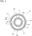
- Fig. 1 is a plan view of a transverse section, illustrating an embodiment of a rotary connector 20 having a flat cable 10 according to the invention installed therein.
- the rotary connector 20 of the present embodiment is used in, for example, a steering device for an automobile, and the rotary connector is disposed between a steering post, which is a static body, and a steering wheel (not shown together in the diagram), which is a rotating body.
- the steering device and the vehicle are electrically connected by the flat cable 10 inside the rotary connector 20, and the flat cable 10 accomplishes the role of transmitting signals from the vehicle side or supplying electric power from a power supply to the various switches and devices inside the steering device.
- the rotary connector 20 has an approximately cylindrical-shaped flat exterior case 21 and a rotary part 22, and has the flat cable 10 installed in the gap S between the two components.
- the exterior case 21 is fixed on the steering post side, while the rotary part 22 is fixed on the steering wheel side, and the two components are connected to each other to be freely rotatable about the same axis.
- the flat cable 10 is accommodated in the gap S such that the width direction of the flat cable follows the axial direction of the exterior case 21 and the rotary part 22.
- One end of the flat cable is connected and fixed to a terminal 21A of the exterior case 21, and the other end is connected and fixed to a terminal 22A of the rotary part 22.
- the flat cable 10 is disposed such that the one side connected to the terminal 21A is wound around the inner circumferential surface 21B of the exterior case 21 in the counterclockwise direction, and the other one side connected to the terminal 22A is wound around the outer circumferential surface of the rotary part 22 in the clockwise direction.
- a bent part 10A at which the direction is reversed exists in the flat cable 10 in the middle region that is not wound around anything. Due to this bent part 10A, the flat cable 10 is configured so as not to stretch out within the range of rotation of the steering wheel (rotary part 22) with respect to the steering post (exterior case 21) .
- the flat cable 10 needs to have excellent flexibility, and specifically, it is preferable that the minimum bending radius at the bent part 10A is from 3 mm to 8 mm.
- the flat cable cannot bend at a bending radius of 8 mm or less, it becomes difficult to accommodate the bent part 10A in the gap S of the rotary connector 20.
- drawbacks such as rupture of the flat cable 10 at the bent part 10A occur.
- the bending radius is 8 mm or less, a smaller bending radius exhibits superior flexibility; however, when the bending radius is less than 3 mm, the flat cable is practically in a folded state. Therefore, flexibility in the range of having a minimum bending radius of less than 3 mm is impractical for accommodation in the rotary connector 20.
- the outer surface of the flat cable 10 and the inner circumferential surface 21B of the exterior case 21 are coated with a lubricating agent (not shown in the diagram) . Due to the surface tension of the lubricating agent, the flat cable can be wound in a state in which one side of the flat cable 10 is in close contact with the inner circumferential surface 21B of the exterior case 21. Furthermore, even in a case in which the steering wheel (rotary part 22) has been rotated, winding collapse of the one side of the flat cable 10 can be prevented.
- the lubricating agent is not particularly limited as long as it provides such an operating effect and is heat-resistant, and agents containing silicone or fluorine, and the like may be used. However, in the present embodiment, a lubricating agent containing an inexpensive hydrocarbon-based material is used.
- the flat cable 10 installed in the rotary connector 20 needs to conduct a large current for heating, and it is preferable that the flat cable is capable of conducting a current of at least 5.5 A. Furthermore, it is preferable that the flat cable 10 installed in the rotary connector 20 does not undergo failure even at a high temperature of at least 80°C, in preparation for an occasion in which the vehicle is parked for a long time in hot weather during the summer.
- the rotary connector 20 illustrated in Fig. 1 has four flat cables 10 installed therein; however, it is not necessarily essential to have four cables installed.
- the number of flat cables can be changed as appropriate according to the number of electric wirings needed by the vehicle. In a case in which the number of installed flat cables 10 is 1 to 3, it is preferable that those terminals 21A and 22A to which flat cables 10 are not connected, are connected with further inexpensive dummy cables. Thereby, symmetry of the rotary connector 20 is maintained, and the centroid position is maintained.
- the number of installments of the flat cable 10 may be 5 or more.
- a plurality of flat cables 10 is disposed evenly on the circumference, and the flat cables are accommodated such that the bent parts 10A of the flat cables 10 do not come into contact with each other even in a case in which the steering wheel (rotary part 22) has been rotated. Generation of abnormal noise caused by contact and the like can be prevented.
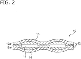
- Fig. 2 shows a cross-sectional view in the width direction of the flat cable 10.
- the flat cable 10 has a plurality of conductors 11 arrayed therein; and an insulating layer 12 covering the periphery of the conductors 11.
- the conductor 11 is a copper foil; however, the conductor is not limited to this and may be formed from any electrically conductive material.
- the insulating layer 12 includes a plurality of layers in a layered form.
- the insulating layer 12 has at least an outermost layer 13 that is in contact with the outside; and an innermost layer 14 that is adhered to the conductors 11.
- the insulating layer 12 may have an intermediate layer (not shown in the diagram) between the outermost layer 13 and the innermost layer 14.
- the outermost layer 13 and the innermost layer 14 are both formed from PPS-based resins.
- the constituent material is not limited to a PPS-based resin.
- the melting point (designated as melting point X) of the PPS-based resin that constitutes the innermost layer 14 is adjusted to be lower by 5°C or more than the melting point (designated as melting point Y) of the PPS-based resin that constitutes the outermost layer 13, in a temperature range of higher than or equal to the melting point X and lower than the melting point Y, the PPS-based resin of the innermost layer 14 can be melted in a state in which the PPS-based resin of the outermost layer 13 is not melted.
- the innermost layer 14 melts as a result of thermal fusion and can cover the periphery of the conductors 11 without a gap.
- the outermost layer 13 does not melt, the insulating layer 12 formed from PPS-based resins can be formed without having a problem that the conductors 11 and the like to be installed therein penetrate through the insulating layer and become exposed at the surface of the flat cable 10.
- a difference in the melting point of 5°C or higher can be provided by adjusting the compositions themselves of the PPS-based resins that constitute the outermost layer and the innermost layer, respectively. Furthermore, even if the compositions of the PPS-based resins are the same, a difference in the presence or absence of melting can be provided by applying a crosslinking treatment.
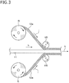
- Fig. 3 is a schematic cross-sectional view illustrating the production method of the present embodiment, and an example of using copper foil as the conductor 11 is illustrated therein.
- the production method is not limited to this, and as long as the conductor is formed from an electrically conductive material, any flat cable 10 can be produced by a similar method.
- conductors 11 are sent out in an arrayed state from a plurality of bobbins (not shown in the diagram) in the direction of arrow h.
- resin films 12a formed from PPS-based resins are sent out from two delivery rolls R, one sheet from each delivery roll, in the directions of arrows i and j, respectively.
- the resin films 12a are introduced in between the roll surfaces of a pair of heating rolls HR, together with the conductors 11, in a state of being in contact with the upper surface and the lower surface of the conductors 11, and the resin films are subjected to thermal compression bonding.
- a flat cable 10 is obtained.
- the thermally compressed flat cable 10 is cooled while being pulled by a winding roll (not shown in the diagram) in the direction of arrow k, and the cooled flat cable is wound around the winding roll.
- the heating rolls HR are not limited to these as long as an apparatus capable of thermal compression bonding is used, and a hot press or the like may also be used.
- the resin film 12a includes a plurality of layers of PPS-based resins having different melting points in a layered form.
- the resin films are sent out in a state of being disposed such that the conductors 11 come into contact with a layer formed from a PPS-based resin having a lower melting point (designated as melting point X), and the heating roll HR comes into contact with a layer formed from a PPS-based resin having a higher melting point (designated as melting point Y).
- the PPS-based resin of the layer contacting the heating roll HR does not melt because the temperature is not above the melting point Y, and the PPS-based resin of the layer contacting the conductors 11 melts because the resin is heated at a temperature higher than or equal to the melting point X.
- the PPS-based resin of the layer contacting the conductors 11 becomes liquid as a result of melting, and as a result of compression bonding, the PPS-based resin goes around the periphery of the conductors 11 as shown in Fig. 2 , while the resin films 12a are thermally fused with each other in the regions between the conductors 11 (dotted lined part in Fig. 2 ).
- the PPS-based resin of the layer contacting the heating roll HR does not melt, a problem such as exposure of the conductors 11 does not occur. Furthermore, since the PPS-based resin of the layer contacting the heating roll HR does not melt, a defect that the conductors 11 freely move around in the width direction and the flat cable 10 is not produced so as to have the dimension in the width direction as originally designed, do not occur.
- the layer adhered to the conductors 11 becomes the innermost layer 14 described above, and the layer contacting the outside such as the heating roll HR becomes the outermost layer 13 described above.
- the melting point X is lower by 5°C or more than the melting point Y.
- the temperature difference is less than 5°C, it is difficult to control the heating of the resin film 12a to a temperature range higher than or equal to the melting point X and lower than melting point Y by means of the heating rolls HR. It is because when the temperature becomes higher than or equal to the melting point Y, all of the layers are melted, or when the temperature becomes lower than the melting point X, none of the layers are melted.
- the layer contacting the heating roll HR has a certain thickness, because drawbacks such as that the outermost layer 13 is torn away, and the conductors 11 and the like installed therein penetrate through the outermost layer and become exposed at the surface of the flat cable 10, are avoided.
- the thickness of the resin film 12a is from 5 ⁇ m to 100 ⁇ m, and the thickness of the layer formed from a PPS-based resin having a higher melting point (outermost layer) is 1 ⁇ m or more.
- a difference of 5°C or more can be provided by making the compositions themselves of the PPS-based resins different.
- two sheets of PPS-based resin films having different compositions can be bonded together by thermal fusion, chemical adhesion using an adhesive, or the like, and thus the resin film 12a can be obtained.
- a layer formed from the adhesive becomes an intermediate layer (not shown in the diagram) between the outermost layer 13 and the innermost layer 14.
- a flat cable 10 that uses PPS-based resins in the insulating layer 12 can be easily produced.
- the thickness, width, sequence, and the like of the conductors 11 since conductors having desired thickness, width, sequence, and the like are selected at the time of sending out, and the conductors are interposed between the resin films 12a and compressed, there is no need to change the production line or the like in accordance with the specifications of the conductors 11. Therefore, the quantity of facility investment is reduced, and production at low cost can be achieved, compared to a production method based on extrusion molding where different nozzle caps are needed for different specifications of the conductors 11.
- the insulating layer 12 (insulating coating) can be produced uniformly. Therefore, the problem that the resin is not introduced uniformly in regions where the distance between the conductors is large and in regions where the distance is small, which is observed in those production methods based on extrusion molding, does not occur. Since production is easy as such, the degree of freedom in design in terms of the thickness, width, sequence, interval, and the like of the conductors is also high.
- an outermost layer formed from a PPS-based resin having a high melting point and an innermost layer formed from a PPS-based resin having a low melting point may be prepared as different resin films 12a1 and 12a2, respectively, and (1) resin film 12a1, (2) resin film 12a2, (3) conductors 11, (4) resin film 12a2, and (5) resin film 12a1 may be overlapped in this order and subjected to thermal compression bonding.
- a similar flat cable 10 can be produced by separately sending out the above-mentioned items (1) to (5), and overlapping them in the order of (1) to (5) at the time of introducing the items into the heating rolls HR.
- a copper foil is bonded to one sheet of resin film 12a such that the copper foil comes into contact with a layer formed from a PPS-based resin having a low melting point, and thereby, a copper-clad film is produced.
- Conductors 11 arrayed on the resin film 12a may be formed by subjecting this copper-clad film to etching processing.
- the conductors 11 arrayed on the resin film 12a as such and another one sheet of resin film 12a are subjected to thermal compression bonding with heating rolls HR or the like such that a layer formed from a PPS-based resin having a low melting point comes into contact with the conductors 11, the flat cable 10 of the present embodiment can be produced.
- the outermost layer and the innermost layer are formed from PPS-based resins.
- the melting point of the PPS-based resin that forms the innermost layer is lower by 5°C or more than the melting point of the PPS-based resin that forms the outermost layer, or the outermost layer is a crosslinked layer, while the innermost layer is a non-crosslinked layer.
- the thickness of the resin film is from 5 ⁇ m to 100 ⁇ m, and the thickness of the outermost layer is 1 ⁇ m or more.
- the outermost layer formed from a PPS-based resin having a high melting point and the innermost layer formed from a PPS-based resin having a low melting point were prepared as different resin films 12a1 and 12a2, respectively, and a flat cable 10 was produced by overlapping (1) resin film 12a1, (2) resin film 12a2, (3) conductors 11 or optical fibers 15, (4) resin film 12a2, and (5) resin film 12a1 in this order and subjecting the assembly to hot pressing.
- Resin films having the melting points and film thicknesses indicated in Table 1, and a plurality of pieces of copper foil each having a width of 0.5 to 10 mm and a thickness of 35 ⁇ m as conductors 11 were used, and the films and the conductors were subjected to thermal compression bonding at 260°C.
- the difference of Examples 1 to 3 is only the film thicknesses of the resin films 12a1 and 12a2 of the outermost layer and the innermost layer.
- Resin films having the melting points and film thicknesses indicated in Table 1, and a plurality of pieces of aluminum foils each having a width of 0.5 to 10 mm and a thickness of 8 ⁇ m as conductors 11 were used, and the films and the conductors were subjected to thermal compression bonding at 250°C.
- Resin films having the melting points and film thicknesses indicated in Table 1, and a plurality of pieces of copper foil each having a width of 0.5 to 10 mm and a thickness of 35 ⁇ m as conductors 11 were used, and the films and the conductors were subjected to thermal compression bonding at 260°C.
- An adhesive (intermediate layer) indicated in Table 1 was also used between the resin films 12a2 and 12a1 of the innermost layer and the outermost layer.
- Resin films having the melting points and film thicknesses indicated in Table 1, and a plurality of pieces of copper foil each having a width of 0.5 to 10 mm and a thickness of 35 ⁇ m as conductors 11 were used, and the films and the conductors were subjected to thermal compression bonding at 277°C.
- Resin films having the melting points and film thicknesses indicated in Table 1, and a plurality of pieces of copper foil each having a width of 0.5 to 10 mm and a thickness of 35 ⁇ m as conductors 11 were used, and the films and the conductors were subjected to thermal compression bonding at 260°C.
- the outermost layer was a layer in a state of being made unmeltable by applying a crosslinking treatment to the layer by preliminary irradiation with an electron beam.
- the innermost layer was not subjected to a crosslinking treatment.
- core 15A was formed from a polymethyl methacrylate-based rein (PMMA)
- clad 15B was formed from a fluorine-based material
- Resin films having the melting points and film thicknesses indicated in Table 1, and a plurality of pieces of copper foil each having a width of 0.5 to 10 mm and a thickness of 35 ⁇ m as conductors 1 were used, and the films and the conductors were subjected to thermal compression bonding at 260°C.
- An intermediate layer formed from a PPS-based resin layer indicated in Table 1 was also formed between the innermost layer and the outermost layer.
- a resin film 12b that served as an intermediate layer was inserted respectively between (1) resin film 12a1 and (2) resin film 12a2, and between (4) resin film 12a2 and (5) resin film 12a1 described above.
- the resin film was formed by applying a flame-retardant polyester-based adhesive dissolved in a solvent on the PET-based resin film as the outermost layer, and drying the adhesive. Two sheets of the resin film formed as such were prepared, and a plurality of pieces of copper foil each having a width of 0.5 to 10 mm and a thickness of 35 ⁇ m were interposed between the two sheets. The assembly was subjected to thermal compression bonding at 160°C, and thereby a flat cable was produced.
- Comparative Example 2 did not satisfy the first part of the above-described Condition 3.
- An outermost layer formed from a PPS-based resin having a high melting point and an innermost layer formed from a PPS-based resin having a low melting point were prepared as different resin films 12a1 and 12a2, respectively, and (1) resin film 12a1, (2) resin film 12a2, (3) conductors 11, (4) resin film 12a2, and (5) resin film 12a1 were overlapped in this order.
- the assembly was subjected to hot pressing, and thereby a flat cable 10 was produced.
- Resin films having the melting points and film thicknesses indicated in Table 2, and a plurality of pieces of copper foil each having a width of 0.5 to 10 mm and a thickness of 35 ⁇ m as conductors 1 were used, and the films and the conductors were subjected to thermal compression bonding at 260°C.
- the resin film a film having a single layer structure in which there was no outermost layer (thickness of the outermost layer was 0), and the innermost layer was formed from a PPS-based resin having a melting point of 250°C, and having a film thickness indicated in Table 2, was used.
- An outermost layer formed from a heat-resistant cycloolefin-based resin having a high melting point and an innermost layer formed from a PPS-based resin having a low melting point were prepared as different resin films 12a1 and 12a2, respectively, and (1) resin film 12a1, (2) resin film 12a2, (3) conductors 11, (4) resin film 12a2, and (5) resin film 12a1 were overlapped in this order.
- the films and the conductors were subjected to hot pressing, and thus a flat cable 10 was produced.
- Resin films having the melting points and film thicknesses indicated in Table 2 and a plurality of pieces of copper foil each having a width of 0.5 to 10 mm and a thickness of 35 ⁇ m as conductors 1 were used, and the films and the conductors were subjected to thermal compression bonding at 260°C.
- An adhesive (intermediate layer) indicated in Table 2 was also used between the innermost layer and the outermost layer.
- the resin film was formed by applying a flame-retardant polyester-based adhesive dissolved in a solvent on the PPS-based resin film as the outermost layer, and drying the adhesive. Two sheets of the resin film formed as such were prepared, and a plurality of pieces of copper foil each having a width of 0.5 to 10 mm and a thickness of 35 ⁇ m were interposed between the two sheets. The assembly was subjected to thermal compression bonding at 160°C, and thereby a flat cable was produced.
- the flat cables of Examples 1 to 9 and Comparative Examples 1 to 5 were cut to a predetermined width and a predetermined length, and then a bending resistance test and a flame resistance test were performed.
- a rotary connector having these flat cables installed as illustrated in Fig. 1 and having the flat cables and the inner circumferential surface of the exterior case coated with a lubricating agent containing a hydrocarbon-based material, a durability test and a test for operation after parking for a long time in hot weather during the summer were performed. These test results are shown in Tables 1 and 2.
- a bending test was carried out by repeating an operation of bending or stretching straight a flat cable at a bending radius of 8 mm at normal temperature (25°C), 80°C, and 130°C, and measuring the number of times until the internal conductors broke. Therefore, as the numbers of the test results shown in Tables 1 and 2 are larger, superior bending resistance is obtained.
- the flame retardance test was carried out according to VW-1 of UL1581 (vertical combustion test).
- the durability test was carried out by rotating a rotary connector counterclockwise and clockwise two times each at a rate of one rotation per second at 80°C and 130°C, and measuring the number of times to reach breaking of flat cables.
- Tables 1 and 2 the ratio of the number of times in the case in which the measured value in Comparative Example 1 (conventional product) was denoted as 1.0 is described. Therefore, as the numbers of the test results shown in Tables 1 and 2 are larger, superior durability is obtained.
- Example 1 Example 2
- Example 3 Example 4
- Example 5 Example 6
- Example 7 Example 8
- Thickness ( ⁇ m) 25 10
- 50 4 25 25 24 50
- Embedded material 35- ⁇ m thick copper foil 35- ⁇ m thick copper foil 35- ⁇ m thick copper foil 8- ⁇ m thick aluminum foil 35- ⁇ m thick copper foil 35- ⁇ m thick copper foil 35- ⁇ m thick copper foil
- Comparative Example 1 was rated as ⁇ .
- Comparative Example 2 With regard to the flat cable of Comparative Example 2, the numbers of times of bending at 80°C and 130°C were 200,000 times and 100,000 times, respectively, and the flat cable did not satisfy the specifications for installment in a rotary connector. Therefore, in the comprehensive evaluation, Comparative Example 2 was regarded as a defective product and was rated as ⁇ .
- Comparative Example 3 With regard to the flat cable of Comparative Example 3, there occurred a defect that the installed conductors 11 and the like penetrate through and become exposed at the surface of the flat cable 10 in the production process, and production itself could not be achieved. Therefore, in the comprehensive evaluation, Comparative Example 3 was rated as ⁇ .
- Comparative Example 4 was unacceptable in the flame retardance test. Furthermore, in a case in which the flat cable was installed in a rotary connector, the flat cable was swollen by a lubricating agent containing a hydrocarbon-based material that was applied on the outer surface, and the thickness became non-uniform. Consequently, poor results were obtained in the test for durability of the rotary connector. Therefore, in the comprehensive evaluation, Comparative Example 4 was rated as ⁇ .
- Comparative Example 5 With regard to the flat cable of Comparative Example 5, there occurred a defect of abnormal noise or winding collapse occurring in the test for operation after parking for a long time in hot weather during the summer. Therefore, in the comprehensive evaluation, Comparative Example 5 was regarded as a defective product and was rated as ⁇ .
Landscapes
- Physics & Mathematics (AREA)
- Engineering & Computer Science (AREA)
- Manufacturing & Machinery (AREA)
- Optics & Photonics (AREA)
- General Physics & Mathematics (AREA)
- Spectroscopy & Molecular Physics (AREA)
- Chemical & Material Sciences (AREA)
- Chemical Kinetics & Catalysis (AREA)
- Thermal Sciences (AREA)
- Organic Chemistry (AREA)
- Polymers & Plastics (AREA)
- Medicinal Chemistry (AREA)
- Health & Medical Sciences (AREA)
- Insulated Conductors (AREA)
Abstract
Description
- The present invention relates to a flat cable used for, for example, a rotary connector to be mounted in a vehicle, a rotary connector using the flat cable, and a method for producing a flat cable.
- Flat cables are widely utilized in various places. For example, a rotary connector for a vehicle, which is used for a steering device, is furnished with a flat cable having excellent flexibility as an electric wiring body. The steering device and the vehicle are electrically connected by a flat cable in a rotary connector, and the flat cable plays the role of causing signals or electric power from the vehicle side to flow into various switches inside the steering device. For example, a detonating signal for activating an airbag at the time of an accident is also transmitted through a flat cable.
- In recent years, due to the progress in the information technology concerning vehicles and the diversification of users' needs, the electric current flowing through a flat cable flows into multiple circuits in large quantities. For example, in a vehicle equipped with a steering heater function that warms the steering device so that the driver does not feel cold on the steering device on cold days, a large current for heating flows through a flat cable. Along with such multi-circuiting and capacity increase of flowing current, there is an increasing demand for a flat cable having high heat resistance and high flame retardance.
- Furthermore, there is a demand for size reduction of rotary connectors where flat cables are accommodated. Therefore, it is expected that in the future, flat cables will be used in environments where heat dissipation is more difficult. For example, in a case in which a vehicle is parked for a long time in hot weather during the summer, the temperature inside a small-sized rotary connector may reach about 80°C. Therefore, even for a vehicle that is not equipped with the steering heater function mentioned above as an example, a flat cable having heat resistance and flame retardance, which can be used even in such a high-temperature region is needed.
- In the case of conventional flat cables, polyester-based resins are generally used for the insulating coating; however, there is a problem that the resins undergo degeneration at a high temperature such as 80°C. Since polyester-based materials have their glass transition temperatures near 70°C, in a case in which a polyester-based material is used in a flat cable, when the polyester-based material is heated to a temperature higher than about 70°C, there occurs a phenomenon in which the shape is remembered (heat setting phenomenon) when the material is heated and then cooled again.
- It is speculated that this shape memory property is exhibited because when the temperature rises above 70°C, which is near the glass transition temperatures of polyesters, a polyester enters the rubbery state so that the molecular chains in the amorphous part can move freely, and when the temperature is lowered, the amorphous part is constrained again as the polyester is returned to the glassy state.
- A flat cable in which the insulating coating has exhibited the heat setting phenomenon enters a curled state in a rotary connector due to shape memory. Since a plurality of flat cables is disposed in a rotary connector as shown in
Fig. 1 (four flat cables inFig. 1 ), when curled flat cables are brought into contact with one another, there is a problem that abnormal noises are generated and defects such as a winding collapse occur. - In order to avoid such problems, it may be considered to use materials other than polyester-based materials as the insulating film. However, materials respectively have problems, for example, vinyl chloride has low heat resistance; polycarbonates have low chemical resistance; polyetherimides have low flexibility; and polyimides are very expensive. When a cycloolefin-based resin having a melting point that is as high as about 250°C is used, as will be described below, the cycloolefin-based resin swells due to a lubricating agent (lubricant oil) containing a hydrocarbon-based material, which is used at the time of mounting flat cables in a rotary connector. As a result, the film thickness of the flat cables becomes non-uniform, load is concentrated on thin parts, and thus, durability is decreased.
- Patent Document 1 discloses a flat cable in which a polyphenylene sulfide (PPS)-based resin is used for the insulating film. Since PPS has a glass transition temperature that is as high as about 90°C, even in a case in which a vehicle is parked for a long time in hot weather during the summer, the heat setting phenomenon is not likely to be exhibited. A PPS-based resin has a melting point that is as high as about 280°C, has high heat resistance, high flame retardance, and high flexibility, and does not have a problem of swelling caused by a lubricating agent. Therefore, a PPS-based resin exhibits excellent durability when mounted in a rotary connector.
- Patent Document 1:
JP 2013-30327 A - However, since the flat cable disclosed in Patent Document 1 is produced by extrusion molding, the production cost is so high that it is very difficult to put the flat cable to practical use. In the case of extrusion molding, an extrusion head and nozzle caps are needed for each case of specifications such as the thickness, width, number of units, and sequence of the conductor. Therefore, in order to cope with flat cables of a variety of specifications, enormous capital investment is required.
- Furthermore, in a case in which the conductor is as thin as several ten micrometers (µm), a drawback that the conductor is cut by extrusion molding is likely to occur, and when the rate of extrusion molding is suppressed in order to prevent this drawback, there occurs a problem that the time required for the production is lengthened. In order to shorten the production time, a method of arranging multiple flat cables in parallel and performing extrusion may also be considered; however, in that case, the manufacturing apparatus must become large-sized in order to cope with a wide nozzle cap, and the facility investment is further increased.
- Generally, with regard to PPS-based resins, the raw materials themselves are expensive compared to the polyester-based resins and the like of conventional products. In addition to that, enormous capital investment is needed due to the extrusion molding process described above, and consequently, practical use of PPS-based resins is not likely to be realized from the viewpoint of production cost.
- In regard to the production achieved by extrusion molding, in a case in which a plurality of conductors having different thicknesses or widths is incorporated into a same flat cable, it is technically difficult to uniformly extrude the resin that becomes the insulating coating. Specifically, there is a difficulty that in a region where the distance between conductors is wide, the resin is extruded in a large amount that is more than needed, and in a region where the distance is narrow, the resin is extruded only in a small amount that is below the required amount. Therefore, the degree of freedom in design is restricted.
- The invention was achieved as a result of addressing the problems described above, and it is an object of the invention to provide a flat cable made of an inexpensive PPS-based resin that exhibits excellent heat resistance, flame retardance, flexibility, and durability and can be produced easily; a rotary connector using this flat cable; and a method for producing the flat cable.
- In order to solve the problems described above, the flat cable according to the invention comprises a plurality of arrayed conductors; and an insulating layer covering the periphery of the conductors with a coating film, wherein the insulating layer includes a plurality of layers, the outermost layer of the insulating layer and the innermost layer contacting the conductor are both formed from polyphenylene sulfide-based resins, and the melting point of the polyphenylene sulfide-based resin that constitutes the innermost layer is lower by 5°C or more than the melting point of the polyphenylene sulfide-based resin that constitutes the outermost layer.
- In order to solve the problems described above, the flat cable according to the invention comprises a plurality of arrayed optical fibers; and a protective layer covering the periphery of the optical fibers with a protective material, wherein the protective layer includes a plurality of layers, the outermost layer of the protective layer and the innermost layer contacting the optical fibers are both formed from polyphenylene sulfide-based resins, and the melting point of the polyphenylene sulfide-based resin that constitutes the innermost layer is lower by 5°C or more than the melting point of the polyphenylene sulfide-based resin that constitutes the outermost layer.
- In the flat cable, the outermost layer may be a crosslinked layer, and the innermost layer may be a non-crosslinked layer.
- In order to solve the problems described above, the rotary connector according to the invention has the aforementioned flat cable installed therein.
- In regard to the rotary connector, it is preferable that the outer surface of the flat cable installed therein and the inner circumferential surface of the exterior case are coated with a lubricating agent containing a hydrocarbon-based material.
- In regard to the rotary connector, it is preferable that the minimum bending radius of the flat cable installed therein is from 3 mm to 8 mm.
- In regard to the rotary connector, it is preferable that the flat cable installed therein is capable of conducting a current of 5.5 A or greater and has a heat-resistance of from 80°C to 275°C.
- In order to solve the problems described above, the method for producing a flat cable according to the invention is a method for producing the above-described flat cable, the method including thermally fusing the innermost layers by thermal compression bonding at a temperature that is higher than or equal to the melting point of the polyphenylene sulfide-based resin that constitutes the innermost layer and is lower than the melting point of the polyphenylene sulfide-based resin that constitutes the outermost layer.
- In order to solve the problems described above, the method for producing a flat cable according to the invention is a method for producing a flat cable by adhering, by thermal fusion, two sheets of resin films containing polyphenylene sulfide-based resins having different melting points in the form of layer, with conductors being interposed therebetween, the method comprising a step of sending out the conductors and the resin films such that the conductors come into contact with a layer formed from a polyphenylene sulfide-based resin having a lower melting point, and the thermal compression bonding apparatus used for thermal fusion is brought into contact with a layer formed from a polyphenylene sulfide-based resin having a higher melting point; and a step of subjecting the conductors and the resin films thus sent out, to thermal compression bonding using the heating apparatus at a temperature that is higher than or equal to the melting point of the layer contacting the conductors and is lower than the melting point of the layer contacting the heating apparatus.
- In order to solve the problems described above, the method for producing a flat cable according to the invention is a method for producing a flat cable by adhering, by thermal fusion, two sheets of resin films containing polyphenylene sulfide-based resins having different melting points in the form of layer, with optical fibers being interposed therebetween, the method comprising a step of sending out the optical fibers and the resin films such that the optical fibers are brought into contact with a layer formed from a polyphenylene sulfide-based resin having a lower melting point and the thermal compression bonding apparatus used for thermal fusion is brought into contact with a layer formed from a polyphenylene sulfide-based resin having a higher melting point; and a step of subjecting the conductors and the resin films thus sent out, to thermal compression bonding using the heating apparatus at a temperature that is higher than or equal to the melting point of the layer contacting the optical fibers and is lower than the melting point of the layer contacting the heating apparatus.
- In the above-described method for producing a flat cable, the two sheets of resin films containing polyphenylene sulfide-based resins having different melting points in the form of layer have been partially subjected to a crosslinking treatment in advance, and the method comprises a step of sending out the conductors, the optical fibers, and the resin films such that the thermal compression bonding apparatus used for thermal fusion is brought into contact with a crosslinked layer, the conductors and the optical fibers are brought into contact with a non-crosslinked layer, while the thermal compression bonding apparatus used for thermal fusion is brought into contact with a crosslinked layer; and a step of subjecting the conductors and the resin films thus sent out, to thermal compression bonding using the heating apparatus at a temperature higher than or equal to the melting point of the layer contacting the conductors, the optical fibers.
- In regard to the method for producing a flat cable, it is preferable that the resin film has a thickness of from 5 µm to 100 µm, and the layer formed from a PPS-based resin that has a high melting point or has been crosslinked, has a thickness of 1 µm or more.
- When the flat cable of the invention, a rotary connector using this flat cable, and a method for producing a flat cable are used, an inexpensive flat cable that is easily producible and has excellent heat resistance, flame retardance and flexibility, and a rotary connector can be realized.
-
-
Fig. 1 is a plan view of a transverse section, illustrating an embodiment of a rotary connector having the flat cable according to the invention installed therein; -
Fig. 2 is a cross-sectional view in the width direction illustrating an embodiment of the flat cable according to the invention, the diagram illustrating an example of embedding copper foil as a conductor; -
Fig. 3 is a schematic cross-sectional view illustrating the method for producing a flat cable according to the invention; and -
Fig. 4 is a cross-sectional view in the width direction illustrating an embodiment of the flat cable according to the invention, the diagram illustrating an example of embedding optical fibers. - Hereinafter, embodiments of the invention will be described with reference to the drawings.
-
Fig. 1 is a plan view of a transverse section, illustrating an embodiment of arotary connector 20 having aflat cable 10 according to the invention installed therein. Therotary connector 20 of the present embodiment is used in, for example, a steering device for an automobile, and the rotary connector is disposed between a steering post, which is a static body, and a steering wheel (not shown together in the diagram), which is a rotating body. The steering device and the vehicle are electrically connected by theflat cable 10 inside therotary connector 20, and theflat cable 10 accomplishes the role of transmitting signals from the vehicle side or supplying electric power from a power supply to the various switches and devices inside the steering device. - As illustrated in
Fig. 1 , therotary connector 20 has an approximately cylindrical-shaped flatexterior case 21 and arotary part 22, and has theflat cable 10 installed in the gap S between the two components. Theexterior case 21 is fixed on the steering post side, while therotary part 22 is fixed on the steering wheel side, and the two components are connected to each other to be freely rotatable about the same axis. - The
flat cable 10 is accommodated in the gap S such that the width direction of the flat cable follows the axial direction of theexterior case 21 and therotary part 22. One end of the flat cable is connected and fixed to a terminal 21A of theexterior case 21, and the other end is connected and fixed to a terminal 22A of therotary part 22. Theflat cable 10 is disposed such that the one side connected to the terminal 21A is wound around the innercircumferential surface 21B of theexterior case 21 in the counterclockwise direction, and the other one side connected to the terminal 22A is wound around the outer circumferential surface of therotary part 22 in the clockwise direction. Since the winding directions of the two ends are reverse directions, abent part 10A at which the direction is reversed exists in theflat cable 10 in the middle region that is not wound around anything. Due to thisbent part 10A, theflat cable 10 is configured so as not to stretch out within the range of rotation of the steering wheel (rotary part 22) with respect to the steering post (exterior case 21) . - Accordingly, the
flat cable 10 needs to have excellent flexibility, and specifically, it is preferable that the minimum bending radius at thebent part 10A is from 3 mm to 8 mm. In a case in which the flat cable cannot bend at a bending radius of 8 mm or less, it becomes difficult to accommodate thebent part 10A in the gap S of therotary connector 20. Even in a case in which the flat cable could be accommodated forcibly, drawbacks such as rupture of theflat cable 10 at thebent part 10A occur. When the bending radius is 8 mm or less, a smaller bending radius exhibits superior flexibility; however, when the bending radius is less than 3 mm, the flat cable is practically in a folded state. Therefore, flexibility in the range of having a minimum bending radius of less than 3 mm is impractical for accommodation in therotary connector 20. - It is preferable that the outer surface of the
flat cable 10 and the innercircumferential surface 21B of theexterior case 21 are coated with a lubricating agent (not shown in the diagram) . Due to the surface tension of the lubricating agent, the flat cable can be wound in a state in which one side of theflat cable 10 is in close contact with the innercircumferential surface 21B of theexterior case 21. Furthermore, even in a case in which the steering wheel (rotary part 22) has been rotated, winding collapse of the one side of theflat cable 10 can be prevented. The lubricating agent is not particularly limited as long as it provides such an operating effect and is heat-resistant, and agents containing silicone or fluorine, and the like may be used. However, in the present embodiment, a lubricating agent containing an inexpensive hydrocarbon-based material is used. - For a flat cable intended for a vehicle provided with the above-described steering heater function, the
flat cable 10 installed in therotary connector 20 needs to conduct a large current for heating, and it is preferable that the flat cable is capable of conducting a current of at least 5.5 A. Furthermore, it is preferable that theflat cable 10 installed in therotary connector 20 does not undergo failure even at a high temperature of at least 80°C, in preparation for an occasion in which the vehicle is parked for a long time in hot weather during the summer. - The
rotary connector 20 illustrated inFig. 1 has fourflat cables 10 installed therein; however, it is not necessarily essential to have four cables installed. The number of flat cables can be changed as appropriate according to the number of electric wirings needed by the vehicle. In a case in which the number of installedflat cables 10 is 1 to 3, it is preferable that thoseterminals flat cables 10 are not connected, are connected with further inexpensive dummy cables. Thereby, symmetry of therotary connector 20 is maintained, and the centroid position is maintained. - Furthermore, in accordance with further multi-circuiting of vehicles, the number of installments of the
flat cable 10 may be 5 or more. However, as shown inFig. 1 , it is preferable that a plurality offlat cables 10 is disposed evenly on the circumference, and the flat cables are accommodated such that thebent parts 10A of theflat cables 10 do not come into contact with each other even in a case in which the steering wheel (rotary part 22) has been rotated. Generation of abnormal noise caused by contact and the like can be prevented. - Next, the details of the
flat cable 10 according to the present embodiment will be described with reference toFig. 2. Fig. 2 shows a cross-sectional view in the width direction of theflat cable 10. Theflat cable 10 has a plurality ofconductors 11 arrayed therein; and an insulatinglayer 12 covering the periphery of theconductors 11. Theconductor 11 is a copper foil; however, the conductor is not limited to this and may be formed from any electrically conductive material. - In the diagram, two
conductors 11 having an identical cross-sectional shape and an identical cross-sectional area are shown. However, it is not necessary for the cross-sectional shape and the cross-sectional area to be identical, and the number ofconductors 11 to be embedded is not limited to two. Furthermore, the distance between theconductors 11 is not limited as long as theconductors 11 are electrically insulated, and the distance can be changed as appropriate according to the desired specifications. - As shown in
Fig. 2 , the insulatinglayer 12 includes a plurality of layers in a layered form. The insulatinglayer 12 has at least anoutermost layer 13 that is in contact with the outside; and aninnermost layer 14 that is adhered to theconductors 11. The insulatinglayer 12 may have an intermediate layer (not shown in the diagram) between theoutermost layer 13 and theinnermost layer 14. Here, theoutermost layer 13 and theinnermost layer 14 are both formed from PPS-based resins. In a case in which the insulating layer has an intermediate layer, the constituent material is not limited to a PPS-based resin. - As such, when the insulating
layer 12 has a structure having a plurality of layers including theoutermost layer 13 and theinnermost layer 14, and the melting point (designated as melting point X) of the PPS-based resin that constitutes theinnermost layer 14 is adjusted to be lower by 5°C or more than the melting point (designated as melting point Y) of the PPS-based resin that constitutes theoutermost layer 13, in a temperature range of higher than or equal to the melting point X and lower than the melting point Y, the PPS-based resin of theinnermost layer 14 can be melted in a state in which the PPS-based resin of theoutermost layer 13 is not melted. Thereby, in the production method that will be described below, when two sheets ofresin films 12a that serve as the insulatinglayer 12 are thermally fused, with theconductors 11 being interposed therebetween, in a temperature range of higher than or equal to the melting point X and lower than the melting point Y, theinnermost layer 14 melts as a result of thermal fusion and can cover the periphery of theconductors 11 without a gap. On the other hand, since theoutermost layer 13 does not melt, the insulatinglayer 12 formed from PPS-based resins can be formed without having a problem that theconductors 11 and the like to be installed therein penetrate through the insulating layer and become exposed at the surface of theflat cable 10. - Regarding the
outermost layer 13 and theinnermost layer 14, a difference in the melting point of 5°C or higher can be provided by adjusting the compositions themselves of the PPS-based resins that constitute the outermost layer and the innermost layer, respectively. Furthermore, even if the compositions of the PPS-based resins are the same, a difference in the presence or absence of melting can be provided by applying a crosslinking treatment. That is, in order to enable prevention of melting through a crosslinking treatment, when a crosslinked layer is disposed as theoutermost layer 13, while a non-crosslinked layer is disposed as theinnermost layer 14, and the PPS-based resins that constitute theoutermost layer 13 and theinnermost layer 14 are heated to a temperature that is higher than or equal to the melting point, it is made possible to melt the innermost layer, without melting the outermost layer. - Next, a method for producing the
flat cable 10 of the present embodiment will be described with reference toFig. 3. Fig. 3 is a schematic cross-sectional view illustrating the production method of the present embodiment, and an example of using copper foil as theconductor 11 is illustrated therein. However, the production method is not limited to this, and as long as the conductor is formed from an electrically conductive material, anyflat cable 10 can be produced by a similar method. - As illustrated in
Fig. 3 ,conductors 11 are sent out in an arrayed state from a plurality of bobbins (not shown in the diagram) in the direction of arrow h. Meanwhile,resin films 12a formed from PPS-based resins are sent out from two delivery rolls R, one sheet from each delivery roll, in the directions of arrows i and j, respectively. Theresin films 12a are introduced in between the roll surfaces of a pair of heating rolls HR, together with theconductors 11, in a state of being in contact with the upper surface and the lower surface of theconductors 11, and the resin films are subjected to thermal compression bonding. Thus, aflat cable 10 is obtained. The thermally compressedflat cable 10 is cooled while being pulled by a winding roll (not shown in the diagram) in the direction of arrow k, and the cooled flat cable is wound around the winding roll. The heating rolls HR are not limited to these as long as an apparatus capable of thermal compression bonding is used, and a hot press or the like may also be used. - The
resin film 12a includes a plurality of layers of PPS-based resins having different melting points in a layered form. When the resin films are sent out from the delivery rolls R, the resin films are sent out in a state of being disposed such that theconductors 11 come into contact with a layer formed from a PPS-based resin having a lower melting point (designated as melting point X), and the heating roll HR comes into contact with a layer formed from a PPS-based resin having a higher melting point (designated as melting point Y). When theresin films 12a thus sent out are heated by the heating rolls HR in a temperature range of higher than or equal to the melting point X and lower than the melting point Y, the PPS-based resin of the layer contacting the heating roll HR does not melt because the temperature is not above the melting point Y, and the PPS-based resin of the layer contacting theconductors 11 melts because the resin is heated at a temperature higher than or equal to the melting point X. Thereby, the PPS-based resin of the layer contacting theconductors 11 becomes liquid as a result of melting, and as a result of compression bonding, the PPS-based resin goes around the periphery of theconductors 11 as shown inFig. 2 , while theresin films 12a are thermally fused with each other in the regions between the conductors 11 (dotted lined part inFig. 2 ). - Meanwhile, since the PPS-based resin of the layer contacting the heating roll HR does not melt, a problem such as exposure of the
conductors 11 does not occur. Furthermore, since the PPS-based resin of the layer contacting the heating roll HR does not melt, a defect that theconductors 11 freely move around in the width direction and theflat cable 10 is not produced so as to have the dimension in the width direction as originally designed, do not occur. - As such, the layer adhered to the
conductors 11 becomes theinnermost layer 14 described above, and the layer contacting the outside such as the heating roll HR becomes theoutermost layer 13 described above. - It is desirable that the melting point X is lower by 5°C or more than the melting point Y. In a case in which the temperature difference is less than 5°C, it is difficult to control the heating of the
resin film 12a to a temperature range higher than or equal to the melting point X and lower than melting point Y by means of the heating rolls HR. It is because when the temperature becomes higher than or equal to the melting point Y, all of the layers are melted, or when the temperature becomes lower than the melting point X, none of the layers are melted. - Furthermore, it is preferable that the layer contacting the heating roll HR has a certain thickness, because drawbacks such as that the
outermost layer 13 is torn away, and theconductors 11 and the like installed therein penetrate through the outermost layer and become exposed at the surface of theflat cable 10, are avoided. Specifically, it is preferable that the thickness of theresin film 12a is from 5 µm to 100 µm, and the thickness of the layer formed from a PPS-based resin having a higher melting point (outermost layer) is 1 µm or more. - For the melting point, a difference of 5°C or more can be provided by making the compositions themselves of the PPS-based resins different. In the process of the previous step illustrated in
Fig. 3 , two sheets of PPS-based resin films having different compositions can be bonded together by thermal fusion, chemical adhesion using an adhesive, or the like, and thus theresin film 12a can be obtained. In the case of using an adhesive, a layer formed from the adhesive becomes an intermediate layer (not shown in the diagram) between theoutermost layer 13 and theinnermost layer 14. - In the previous step of the process illustrated in
Fig. 3 , when one surface of theresin film 12a is subjected to a crosslinking treatment by chemical crosslinking by incorporation of a crosslinking agent, irradiation with an electron beam, or the like, a layer that does not melt is formed. Therefore, a PPS-basedresin film 12a having a surface that does melts and a surface that does not melt can be realized. - By subjecting the
resin film 12a thus obtained to thermal compression bonding in a state of having theconductors 11 interposed therebetween, aflat cable 10 that uses PPS-based resins in the insulatinglayer 12 can be easily produced. Regarding the thickness, width, sequence, and the like of theconductors 11, since conductors having desired thickness, width, sequence, and the like are selected at the time of sending out, and the conductors are interposed between theresin films 12a and compressed, there is no need to change the production line or the like in accordance with the specifications of theconductors 11. Therefore, the quantity of facility investment is reduced, and production at low cost can be achieved, compared to a production method based on extrusion molding where different nozzle caps are needed for different specifications of theconductors 11. - Furthermore, at the time of performing thermal compression bonding of two sheets of
resin films 12a withconductors 11 interposed therebetween, since molten PPS-based resin layers go evenly around the periphery of theconductors 11, even in the case of including conductors having different thicknesses or widths, the insulating layer 12 (insulating coating) can be produced uniformly. Therefore, the problem that the resin is not introduced uniformly in regions where the distance between the conductors is large and in regions where the distance is small, which is observed in those production methods based on extrusion molding, does not occur. Since production is easy as such, the degree of freedom in design in terms of the thickness, width, sequence, interval, and the like of the conductors is also high. - In the case of using a hot press, an outermost layer formed from a PPS-based resin having a high melting point and an innermost layer formed from a PPS-based resin having a low melting point may be prepared as different resin films 12a1 and 12a2, respectively, and (1) resin film 12a1, (2) resin film 12a2, (3)
conductors 11, (4) resin film 12a2, and (5) resin film 12a1 may be overlapped in this order and subjected to thermal compression bonding. Also, in the case of using heating rolls HR, a similarflat cable 10 can be produced by separately sending out the above-mentioned items (1) to (5), and overlapping them in the order of (1) to (5) at the time of introducing the items into the heating rolls HR. - Thus, embodiments of the invention have been explained; however, the invention is not intended to be limited to the embodiments described above, and various modifications can be carried out to the extent that the gist of the invention is maintained. For example, the
conductors 11 may be changed as will be described in the Examples described below, andoptical fibers 15 that propagate optical signals may be embedded in a protective layer 17 (seeFig. 4 ). Furthermore, conductors of different kinds, such as copper foil and optical fibers, may be embedded in combination in the sameflat cable 10. - Furthermore, as another embodiment of the production method, a copper foil is bonded to one sheet of
resin film 12a such that the copper foil comes into contact with a layer formed from a PPS-based resin having a low melting point, and thereby, a copper-clad film is produced.Conductors 11 arrayed on theresin film 12a may be formed by subjecting this copper-clad film to etching processing. When theconductors 11 arrayed on theresin film 12a as such and another one sheet ofresin film 12a are subjected to thermal compression bonding with heating rolls HR or the like such that a layer formed from a PPS-based resin having a low melting point comes into contact with theconductors 11, theflat cable 10 of the present embodiment can be produced. - Next, in order to further clarify the effects of the invention, Examples and Comparative Examples will be described in detail; however, the invention is not intended to be limited to these Examples. Examples are equivalent to the
flat cable 10 explained in the embodiments described above and arotary connector 20 having this flat cable installed therein, and satisfy all of the following conditions. - (Condition 1) The outermost layer and the innermost layer are formed from PPS-based resins.
- (Condition 2) The melting point of the PPS-based resin that forms the innermost layer is lower by 5°C or more than the melting point of the PPS-based resin that forms the outermost layer, or the outermost layer is a crosslinked layer, while the innermost layer is a non-crosslinked layer.
- (Condition 3) The thickness of the resin film is from 5 µm to 100 µm, and the thickness of the outermost layer is 1 µm or more.
- In the Examples, the outermost layer formed from a PPS-based resin having a high melting point and the innermost layer formed from a PPS-based resin having a low melting point were prepared as different resin films 12a1 and 12a2, respectively, and a
flat cable 10 was produced by overlapping (1) resin film 12a1, (2) resin film 12a2, (3)conductors 11 oroptical fibers 15, (4) resin film 12a2, and (5) resin film 12a1 in this order and subjecting the assembly to hot pressing. - Resin films having the melting points and film thicknesses indicated in Table 1, and a plurality of pieces of copper foil each having a width of 0.5 to 10 mm and a thickness of 35 µm as
conductors 11 were used, and the films and the conductors were subjected to thermal compression bonding at 260°C. The difference of Examples 1 to 3 is only the film thicknesses of the resin films 12a1 and 12a2 of the outermost layer and the innermost layer. - Resin films having the melting points and film thicknesses indicated in Table 1, and a plurality of pieces of aluminum foils each having a width of 0.5 to 10 mm and a thickness of 8 µm as
conductors 11 were used, and the films and the conductors were subjected to thermal compression bonding at 250°C. - Resin films having the melting points and film thicknesses indicated in Table 1, and a plurality of pieces of copper foil each having a width of 0.5 to 10 mm and a thickness of 35 µm as
conductors 11 were used, and the films and the conductors were subjected to thermal compression bonding at 260°C. An adhesive (intermediate layer) indicated in Table 1 was also used between the resin films 12a2 and 12a1 of the innermost layer and the outermost layer. - Resin films having the melting points and film thicknesses indicated in Table 1, and a plurality of pieces of copper foil each having a width of 0.5 to 10 mm and a thickness of 35 µm as
conductors 11 were used, and the films and the conductors were subjected to thermal compression bonding at 277°C. - Resin films having the melting points and film thicknesses indicated in Table 1, and a plurality of pieces of copper foil each having a width of 0.5 to 10 mm and a thickness of 35 µm as
conductors 11 were used, and the films and the conductors were subjected to thermal compression bonding at 260°C. The outermost layer was a layer in a state of being made unmeltable by applying a crosslinking treatment to the layer by preliminary irradiation with an electron beam. The innermost layer was not subjected to a crosslinking treatment. - Resin films having the melting points and film thicknesses indicated in Table 1, and a plurality of pieces of an
optical fiber 15 having an outer diameter of about 1 mm, in whichcore 15A was formed from a polymethyl methacrylate-based rein (PMMA) and clad 15B was formed from a fluorine-based material, were used, and the films and the optical fibers were subjected to thermal compression bonding at 260°C. - Resin films having the melting points and film thicknesses indicated in Table 1, and a plurality of pieces of copper foil each having a width of 0.5 to 10 mm and a thickness of 35 µm as conductors 1 were used, and the films and the conductors were subjected to thermal compression bonding at 260°C. An intermediate layer formed from a PPS-based resin layer indicated in Table 1 was also formed between the innermost layer and the outermost layer.
- That is, a resin film 12b that served as an intermediate layer was inserted respectively between (1) resin film 12a1 and (2) resin film 12a2, and between (4) resin film 12a2 and (5) resin film 12a1 described above.
- In order to make a comparison with the Examples, flat cables as Comparative Examples were produced. Unlike the Examples, the Comparative Examples did not satisfy at least one of the above-described three conditions.
- Comparative Example 1 did not satisfy the above-described Condition 1.
- A film having a two-layer structure in which the outermost layer was a layer formed from a polyester (PET) -based resin having a melting point of 250°C and the innermost layer was a layer formed from a flame-retardant polyester-based adhesive having a melting point of 120°C, and having a film thickness indicated in Table 2, was used as the resin film. The resin film was formed by applying a flame-retardant polyester-based adhesive dissolved in a solvent on the PET-based resin film as the outermost layer, and drying the adhesive. Two sheets of the resin film formed as such were prepared, and a plurality of pieces of copper foil each having a width of 0.5 to 10 mm and a thickness of 35 µm were interposed between the two sheets. The assembly was subjected to thermal compression bonding at 160°C, and thereby a flat cable was produced.
- Comparative Example 2 did not satisfy the first part of the above-described Condition 3.
- An outermost layer formed from a PPS-based resin having a high melting point and an innermost layer formed from a PPS-based resin having a low melting point were prepared as different resin films 12a1 and 12a2, respectively, and (1) resin film 12a1, (2) resin film 12a2, (3)
conductors 11, (4) resin film 12a2, and (5) resin film 12a1 were overlapped in this order. The assembly was subjected to hot pressing, and thereby aflat cable 10 was produced. - Resin films having the melting points and film thicknesses indicated in Table 2, and a plurality of pieces of copper foil each having a width of 0.5 to 10 mm and a thickness of 35 µm as conductors 1 were used, and the films and the conductors were subjected to thermal compression bonding at 260°C.
- Comparative Example 3 did not satisfy the second part of the above-described Condition 3.
- As the resin film, a film having a single layer structure in which there was no outermost layer (thickness of the outermost layer was 0), and the innermost layer was formed from a PPS-based resin having a melting point of 250°C, and having a film thickness indicated in Table 2, was used.
- Comparative Example 4 did not satisfy the above-described Condition 1.
- An outermost layer formed from a heat-resistant cycloolefin-based resin having a high melting point and an innermost layer formed from a PPS-based resin having a low melting point were prepared as different resin films 12a1 and 12a2, respectively, and (1) resin film 12a1, (2) resin film 12a2, (3)
conductors 11, (4) resin film 12a2, and (5) resin film 12a1 were overlapped in this order. The films and the conductors were subjected to hot pressing, and thus aflat cable 10 was produced. - Resin films having the melting points and film thicknesses indicated in Table 2, and a plurality of pieces of copper foil each having a width of 0.5 to 10 mm and a thickness of 35 µm as conductors 1 were used, and the films and the conductors were subjected to thermal compression bonding at 260°C. An adhesive (intermediate layer) indicated in Table 2 was also used between the innermost layer and the outermost layer.
- Comparative Example 5 did not satisfy the above-described Condition 1.
- A film having a two-layer structure in which the outermost layer was a layer formed from a PPS-based resin having a melting point of 280°C and the innermost layer was a layer formed from a flame-retardant polyester-based adhesive having a melting point of 120°C, and having a film thickness indicated in Table 2, was used as the resin film. The resin film was formed by applying a flame-retardant polyester-based adhesive dissolved in a solvent on the PPS-based resin film as the outermost layer, and drying the adhesive. Two sheets of the resin film formed as such were prepared, and a plurality of pieces of copper foil each having a width of 0.5 to 10 mm and a thickness of 35 µm were interposed between the two sheets. The assembly was subjected to thermal compression bonding at 160°C, and thereby a flat cable was produced.
- The flat cables of Examples 1 to 9 and Comparative Examples 1 to 5 were cut to a predetermined width and a predetermined length, and then a bending resistance test and a flame resistance test were performed. For a rotary connector having these flat cables installed as illustrated in
Fig. 1 and having the flat cables and the inner circumferential surface of the exterior case coated with a lubricating agent containing a hydrocarbon-based material, a durability test and a test for operation after parking for a long time in hot weather during the summer were performed. These test results are shown in Tables 1 and 2. - A bending test was carried out by repeating an operation of bending or stretching straight a flat cable at a bending radius of 8 mm at normal temperature (25°C), 80°C, and 130°C, and measuring the number of times until the internal conductors broke. Therefore, as the numbers of the test results shown in Tables 1 and 2 are larger, superior bending resistance is obtained.
- The flame retardance test was carried out according to VW-1 of UL1581 (vertical combustion test).
- The durability test was carried out by rotating a rotary connector counterclockwise and clockwise two times each at a rate of one rotation per second at 80°C and 130°C, and measuring the number of times to reach breaking of flat cables. In Tables 1 and 2, the ratio of the number of times in the case in which the measured value in Comparative Example 1 (conventional product) was denoted as 1.0 is described. Therefore, as the numbers of the test results shown in Tables 1 and 2 are larger, superior durability is obtained.
- An automobile left in a parking place that is exposed to direct sunlight in the midsummer was assumed, and a rotary connector was left in a constant temperature chamber at 80°C for 8 hours and then was rapidly cooled. The temperature of the entire connector was lowered to -30°C, subsequently the axis of rotation was rotated, and the operation was checked. The case in which the rotary connector did not operate smoothly due to excessive rotational torque, winding collapse of flat cables, and the like, or abnormal noise that is generated when the flat cables rises up from the inner surface of the rotary connector case was generated, was rated as X; and the case in which the flat cables did not rise up and operated normally at a rate of ±2 rotations each, was rated as ○.
[Table 1] Example 1 Example 2 Example 3 Example 4 Example 5 Example 6 Example 7 Example 8 Example 9 Outermost layer Type PPS-based resin PPS-based resin subjected to crosslinking treatment PPS-based resin Melting point (°C) 280 280 280 280 280 280 250 280 280 Thickness (µm) 25 25 50 1 18 25 1 25 25 Intermediate layer - - - - Epoxy-based primer (1 µm thick) - - - PPS-based resin (melting point: 275°C, thickne ss: 5 µm) Innermost layer Type PPS-based resin Melting point (°C) 250 250 250 250 250 275 250 250 250 Thickness (µm) 25 10 50 4 25 25 24 50 20 Embedded material 35-µm thick copper foil 35-µm thick copper foil 35-µm thick copper foil 8-µm thick aluminum foil 35-µm thick copper foil 35-µm thick copper foil 35-µm thick copper foil Optic al fibers (outer diameter: 1 mm) 35-µm thick copper foil Test for bending resistance of flat cable (number of times of bending ) Normal temperature (10,000 times) >1000 >100 0 >100 0 200 >1000 >100 0 >1000 500 >1000 80°C (10,000 times) >100 0 >100 0 100 100 >1000 >100 0 >1000 200 >1000 130°C (10,000 times) >100 0 >100 0 100 100 >1000 >100 0 >1000 100 >1000 Test for flame retardance of flat cable ○ ○ ○ ○ ○ ○ ○ ○ ○ Test for durability of rotary connector (ratio of number of times of rotational durability) 80°C 1.5 1.5 1.0 1.0 1.5 1.5 1.5 1.5 1.5 130°C 3.0 3.0 1.5 1.5 3.0 3.0 3.0 3.0 3.0 Operation of rotary connector after parking for long time in hot weather . during summer ○ ○ ○ ○ ○ ○ ○ ○ ○ Comprehensive evaluation ⊙ ⊙ ○ ○ ⊙ ⊙ ⊙ ○ ⊙ - As shown in Table 1, with regard to the flat cables of Examples 1 to 9, satisfactory results were obtained in the bending resistance test and the flame retardance test. Furthermore, with regard to the rotary connectors having these flat cables installed therein, satisfactory results were obtained in the durability test and the test for operation after parking for a long time in hot weather during the summer. These test results were comprehensively evaluated. Since Examples 1, 2, 5, 6, 7, and 9 showed particularly excellent bending resistance of flat cables, those Examples were regarded as best products and were rated as ⊙; and Examples other than those were regarded as good products and were rated as ○.
[Table 2] Comparative Example 1 Comparative Example 2 Comparative Example 3 Comparative Example 4 Comparative Example 5 Outermost layer Type PET-based resin PPS-based resin Heat-resistant cycloolefin-based resin PPS-based resin Melting point (°C) 250 280 - 265 280 Thicknes s (µm) 25 1 0 25 25 Intermediate layer - - - Epoxy-based primer (1 µm thick) - Innermost layer Type Flame-retard ant polyester-based adhesive PPS-based resin Flame-retardant polyester-based adhesive Melting point (°C) 120 250 250 250 120 Thickness (µm) 25 2 25 25 25 Embedded material 35-µm thick copper foil - - 35-µm thick copper foil 35-µm thick copper foil Test for bending resistance of flat cable (number of times of bending) Normal temperature (10,000 times) >1000 100 - >1000 >1000 80°C (10,000 times) 100 20 - 200 100 130°C (10,000 times) 50 10 - 100 50 Test for flame retardance of flat cable ○ ○ - × ○ Test for durability of rotary connector (ratio of number of times of rotational durability) 80°C 1.0 - - 0.2 1.0 130°C 1.0 - - 0.1 1.0 Operation of rotary connector after parking for long time in hot weather during summer × - - ○ × Comprehensive evaluation × × × × × - In contrast, in regard to a rotary connector having the flat cable of Comparative Example 1 in Table 2 installed therein, defects such as the occurrence of abnormal noise or winding collapse occurred in a test for operation after parking for a long time in hot weather during the summer. Thus, in the comprehensive evaluation, Comparative Example 1 was rated as ×.
- With regard to the flat cable of Comparative Example 2, the numbers of times of bending at 80°C and 130°C were 200,000 times and 100,000 times, respectively, and the flat cable did not satisfy the specifications for installment in a rotary connector. Therefore, in the comprehensive evaluation, Comparative Example 2 was regarded as a defective product and was rated as ×.
- With regard to the flat cable of Comparative Example 3, there occurred a defect that the installed
conductors 11 and the like penetrate through and become exposed at the surface of theflat cable 10 in the production process, and production itself could not be achieved. Therefore, in the comprehensive evaluation, Comparative Example 3 was rated as ×. - The flat cable of Comparative Example 4 was unacceptable in the flame retardance test. Furthermore, in a case in which the flat cable was installed in a rotary connector, the flat cable was swollen by a lubricating agent containing a hydrocarbon-based material that was applied on the outer surface, and the thickness became non-uniform. Consequently, poor results were obtained in the test for durability of the rotary connector. Therefore, in the comprehensive evaluation, Comparative Example 4 was rated as ×.
- With regard to the flat cable of Comparative Example 5, there occurred a defect of abnormal noise or winding collapse occurring in the test for operation after parking for a long time in hot weather during the summer. Therefore, in the comprehensive evaluation, Comparative Example 5 was regarded as a defective product and was rated as ×.
-
- 10 FLAT CABLE
- 11 CONDUCTOR
- 12 INSULATING LAYER
- 12a RESIN FILM
- 13 OUTERMOST LAYER
- 14 INNERMOST LAYER
- 15 OPTICAL FIBER
- 17 PROTECTIVE LAYER
- 20 ROTARY CONNECTOR
- 21 EXTERIOR CASE
- 21B INNER CIRCUMFERENTIAL SURFACE OF EXTERIOR CASE
- 22 ROTARY PART
- HR HEATING ROLL (THERMAL COMPRESSION BONDING APPARATUS)
Claims (14)
- A flat cable comprising a plurality of arrayed conductors;
and an insulating layer covering the periphery of the conductors with a film coating,
wherein the insulating layer includes a plurality of layers,
the outermost layer of the insulating layer and the innermost layer contacting the conductors are both formed from polyphenylene sulfide-based resins, and
the melting point of the polyphenylene sulfide-based resin constituting the innermost layer is lower by 5°C or more than the melting point of the polyphenylene sulfide-based resin constituting the outermost layer. - A flat cable comprising a plurality of arrayed optical fibers; and a protective layer covering the periphery of the optical fibers with a protective material, wherein the protective layer includes a plurality of layers,
the outermost layer of the protective layer and the innermost layer contacting the optical fibers are both formed from polyphenylene sulfide-based resins, and the melting point of the polyphenylene sulfide-based resin constituting the innermost layer is lower by 5°C or more than the melting point of the polyphenylene sulfide-based resin constituting the outermost layer. - A flat cable comprising a plurality of arrayed conductors;
and an insulating layer covering the periphery of the conductors with a film coating,
wherein the insulating layer includes a plurality of layers,
the outermost layer of the insulating layer and the innermost layer contacting the conductors are both formed from polyphenylene sulfide-based resins, and
the outermost layer is a crosslinked layer, while the innermost layer is a non-crosslinked layer. - A flat cable comprising a plurality of arrayed optical fibers; and a protective layer covering the periphery of the optical fibers with a protective material, wherein the protective layer includes a plurality of layers,
the outermost layer of the protective layer and the innermost layer contacting the optical fibers are both formed from polyphenylene sulfide-based resins, and the outermost layer is a crosslinked layer, while the innermost layer is a non-crosslinked layer. - A rotary connector comprising the flat cable according to any one of claims 1 to 4 installed therein.
- The rotary connector according to claim 5, wherein the outer surface of the installed flat cable and the inner circumferential surface of the exterior case are coated with a lubricating agent containing a hydrocarbon-based material.
- The rotary connector according to claim 5 or 6, wherein the minimum bending radius of the installed flat cable is from 3 mm to 8 mm.
- The rotary connector according to any one of claims 5 to 7, wherein the installed flat cable is capable of conducting a current of 5.5 A or greater and has a heat-resistance of from 80°C to 275°C.
- The rotary connector according to claim 8, wherein the installed flat cable is capable of conducting a current of 5.5 A or greater and has a heat-resistance of from 80°C to 250°C.
- A method for producing the flat cable according to claim 1 or 2, the method comprising thermally fusing the innermost layers by thermal compression bonding at a temperature higher than or equal to the melting point of the polyphenylene sulfide-based resin constituting the innermost layer and lower than the melting point of the polyphenylene sulfide-based resin constituting the outermost layer.
- A method for producing a flat cable by adhering, through thermal fusion, two sheets of resin films containing polyphenylene sulfide-based resins having different melting points in the form of layer, with conductors being interposed therebetween,
the method comprising:a step of sending out the conductors and the resin films such that the conductors come into contact with a layer formed from a polyphenylene sulfide-based resin having a lower melting point, and a thermal compression bonding apparatus used for thermal fusion comes into contact with a layer formed from a polyphenylene sulfide-based resin having a higher melting point; anda step of subjecting the conductors and the resin films thus sent out, to thermal compression bonding using the heating apparatus at a temperature higher than or equal to the melting point of the layer contacting the conductors and lower than the melting point of the layer contacting the heating apparatus. - A method for producing a flat cable by adhering, through thermal fusion, two sheets of resin films containing polyphenylene sulfide-based resins having different melting points in the form of layer, with optical fibers being interposed therebetween,
the method comprising:a step of sending out the optical fibers and the resin films such that the optical fibers come into contact with a layer formed from a polyphenylene sulfide-based resin having a lower melting point, and a thermal compression bonding apparatus used for thermal fusion comes into contact with a layer formed from a polyphenylene sulfide-based resin having a higher melting point; anda step of subjecting the conductors and the resin films thus sent out, to thermal compression bonding using the heating apparatus at a temperature higher than or equal to the melting point of the layer contacting the optical fibers and lower than the melting point of the layer contacting the heating apparatus. - The method for producing a flat cable according to claim 11 or 12, wherein the two sheets of resin films containing polyphenylene sulfide-based resins having different melting points in the form of layer have been partially subjected to a crosslinking treatment in advance, a crosslinked layer is disposed instead of the layer formed from a polyphenylene sulfide-based resin having a higher melting point, and a non-crosslinked layer is disposed instead of the layer formed from a polyphenylene sulfide-based resin having a low melting point.
- The method for producing a flat cable according to any one of claims 11 to 13, wherein the resin films have a thickness of from 5 µm to 100 µm, and the layer formed from a PPS-based resin that has a higher melting point or has been crosslinking-treated, has a thickness of 1 µm or more.
Applications Claiming Priority (2)
| Application Number | Priority Date | Filing Date | Title |
|---|---|---|---|
| JP2016162514A JP6678540B2 (en) | 2016-08-23 | 2016-08-23 | Flat cable, rotary connector using the same, and method of manufacturing flat cable |
| PCT/JP2017/026438 WO2018037793A1 (en) | 2016-08-23 | 2017-07-21 | Flat cable, rotary connector in which same is used, and method for manufacturing flat cable |
Publications (2)
| Publication Number | Publication Date |
|---|---|
| EP3506322A1 true EP3506322A1 (en) | 2019-07-03 |
| EP3506322A4 EP3506322A4 (en) | 2020-08-19 |
Family
ID=61245797
Family Applications (1)
| Application Number | Title | Priority Date | Filing Date |
|---|---|---|---|
| EP17843279.5A Pending EP3506322A4 (en) | 2016-08-23 | 2017-07-21 | FLAT CABLE, THE ROTATING CONNECTOR USED IN IT AND METHOD OF MANUFACTURING A FLAT CABLE |
Country Status (6)
| Country | Link |
|---|---|
| US (1) | US10804011B2 (en) |
| EP (1) | EP3506322A4 (en) |
| JP (1) | JP6678540B2 (en) |
| KR (1) | KR102237395B1 (en) |
| CN (1) | CN109196603B (en) |
| WO (1) | WO2018037793A1 (en) |
Families Citing this family (9)
| Publication number | Priority date | Publication date | Assignee | Title |
|---|---|---|---|---|
| CN110310768A (en) * | 2019-06-19 | 2019-10-08 | 芜湖航天特种电缆厂股份有限公司 | Resistance to flexion, the ribbon cable of resist bending fatigue and preparation method thereof |
| CN112151211A (en) * | 2020-08-10 | 2020-12-29 | 中亚世纪(天津)科技有限公司 | Ultrathin flexible flat radio frequency communication cable |
| JP7476767B2 (en) * | 2020-11-13 | 2024-05-01 | 株式会社プロテリアル | Composite Cable |
| CN114188101B (en) * | 2021-12-03 | 2025-10-10 | 盛天先进技术研究(湖北)有限公司 | Insulation coating method for overhead high-voltage wire |
| US12500010B2 (en) * | 2021-12-28 | 2025-12-16 | Koumeican Co., Ltd. | Flat cable having conductive thin plate covered with an insulating layer |
| KR20240152293A (en) * | 2022-02-23 | 2024-10-21 | 쿠라베 가부시키가이샤 | Code-shaped heater and surface-shaped heater |
| JP7781046B2 (en) * | 2022-11-23 | 2025-12-05 | 株式会社クラベ | Cord heaters and surface heaters |
| JP7780976B2 (en) * | 2022-02-23 | 2025-12-05 | 株式会社クラベ | Cord heaters and surface heaters |
| CN120527065B (en) * | 2025-07-23 | 2025-09-23 | 江苏鸿翔电缆有限公司 | A low-voltage cable |
Family Cites Families (23)
| Publication number | Priority date | Publication date | Assignee | Title |
|---|---|---|---|---|
| US4783579A (en) * | 1986-04-29 | 1988-11-08 | Amp Incorporated | Flat multi-conductor power cable with two insulating layers |
| JP2870348B2 (en) * | 1992-05-18 | 1999-03-17 | 住友電気工業株式会社 | Flat cable |
| US6042902A (en) * | 1997-10-20 | 2000-03-28 | Hoechst Celanese Corporation | Adhesives for making multilayer films comprising liquid crystalline polymers and poly(ethylene terephthalate) or polycarbonate |
| US6452138B1 (en) * | 1998-09-25 | 2002-09-17 | Thermosoft International Corporation | Multi-conductor soft heating element |
| US6563094B2 (en) * | 1999-05-11 | 2003-05-13 | Thermosoft International Corporation | Soft electrical heater with continuous temperature sensing |
| JP2003016851A (en) * | 2001-07-04 | 2003-01-17 | Hitachi Cable Ltd | Environmentally friendly flexible flat cable |
| JP4193381B2 (en) * | 2001-07-16 | 2008-12-10 | 日立電線株式会社 | Bending-resistant flexible flat cable and manufacturing method thereof |
| US20060249298A1 (en) * | 2004-07-13 | 2006-11-09 | David Reece | Electrical cable having a surface with reduced coefficient of friction |
| US20060065428A1 (en) | 2004-07-13 | 2006-03-30 | Kummer Randy D | Electrical cable having a surface with reduced coefficient of friction |
| JP4947943B2 (en) * | 2005-09-20 | 2012-06-06 | 古河電気工業株式会社 | Flat cable and manufacturing method thereof |
| JP2009076281A (en) * | 2007-09-19 | 2009-04-09 | Furukawa Electric Co Ltd:The | Rotating connector and flat cable used therefor |
| JP5105242B2 (en) * | 2008-04-09 | 2012-12-26 | 住友電気工業株式会社 | Flame retardant resin composition, insulated wire and flat cable using the same |
| RU2513866C2 (en) * | 2009-08-05 | 2014-04-20 | Призмиан С.П.А. | Flat power cable |
| JP2011204503A (en) * | 2010-03-26 | 2011-10-13 | Hitachi Cable Fine Tech Ltd | Flexible flat cable |
| CN102280181A (en) * | 2010-06-10 | 2011-12-14 | 住友电气工业株式会社 | Method for manufacturing flat cable |
| JP5664525B2 (en) | 2011-04-07 | 2015-02-04 | 日立金属株式会社 | Adhesive film and flat cable using the same |
| JP2013030327A (en) * | 2011-07-27 | 2013-02-07 | Yazaki Corp | Flat cable, and manufacturing method therefor |
| JP5699971B2 (en) * | 2012-03-28 | 2015-04-15 | 日立金属株式会社 | Insulated wire |
| CN103650068B (en) * | 2012-06-15 | 2017-09-08 | 住友电气工业株式会社 | Flat cable dielectric film and flat cable |
| JP6257883B2 (en) * | 2012-07-10 | 2018-01-10 | 大日本印刷株式会社 | Covering material for flexible flat cable |
| JP5712993B2 (en) * | 2012-12-10 | 2015-05-07 | 日立金属株式会社 | Adhesive resin composition, and adhesive film and flat cable using the same |
| JP2015147413A (en) * | 2014-01-10 | 2015-08-20 | 東レ株式会社 | Laminated polyarylene sulfide film |
| JP7032038B2 (en) * | 2016-05-02 | 2022-03-08 | 住友電気工業株式会社 | cable |
-
2016
- 2016-08-23 JP JP2016162514A patent/JP6678540B2/en active Active
-
2017
- 2017-07-21 KR KR1020187033597A patent/KR102237395B1/en active Active
- 2017-07-21 CN CN201780032831.9A patent/CN109196603B/en active Active
- 2017-07-21 EP EP17843279.5A patent/EP3506322A4/en active Pending
- 2017-07-21 WO PCT/JP2017/026438 patent/WO2018037793A1/en not_active Ceased
-
2019
- 2019-02-14 US US16/275,740 patent/US10804011B2/en active Active
Also Published As
| Publication number | Publication date |
|---|---|
| EP3506322A4 (en) | 2020-08-19 |
| US20190189308A1 (en) | 2019-06-20 |
| JP2018032486A (en) | 2018-03-01 |
| KR20190033467A (en) | 2019-03-29 |
| US10804011B2 (en) | 2020-10-13 |
| CN109196603B (en) | 2021-11-16 |
| CN109196603A (en) | 2019-01-11 |
| JP6678540B2 (en) | 2020-04-08 |
| KR102237395B1 (en) | 2021-04-07 |
| WO2018037793A1 (en) | 2018-03-01 |
Similar Documents
| Publication | Publication Date | Title |
|---|---|---|
| US10804011B2 (en) | Flat cable, rotary connector using the same, and method for producing flat cable | |
| EP3193338B1 (en) | Insulated electric wire, coil, electric/electronic device, and method for manufacturing insulated electric wire | |
| JP4876335B2 (en) | Flat cable covering material and flat cable using the same | |
| US11615914B2 (en) | Magnet wire with thermoplastic insulation | |
| EP0258036B1 (en) | Insulated conductor with multi-layer high temperature insulation | |
| US20210102068A1 (en) | Polymeric insulating films | |
| WO2011010558A1 (en) | Harness composed of coaxial cables | |
| US20080128154A1 (en) | Method for Producing a Winding Conductor for Electrical Appliances, and Winding Conductor Producing According to Said Method | |
| JP2019149242A (en) | Flat cable, and rotation connector including the same | |
| US6392155B1 (en) | Flat cable and process for producing the same | |
| CN103839612A (en) | Insulation wire and making method thereof | |
| KR101976501B1 (en) | Insulating film and flexible flat cable | |
| JP2014191885A (en) | Flat cable and method for manufacturing the same | |
| JP2020098717A (en) | Resin film for conductive element wire and method for manufacturing the same, and rectangular electric wire | |
| JP2017117627A (en) | Insulation sheet and flat cable | |
| JP5635901B2 (en) | Molded body for preventing electric leakage and electric shock | |
| JP6782125B2 (en) | Rotating connector device | |
| JP4947943B2 (en) | Flat cable and manufacturing method thereof | |
| CN214124791U (en) | 35kV and following cable are around package butt fusion formula intermediate head | |
| JP2580413Y2 (en) | Insulated wires and coaxial cables | |
| JP7737888B2 (en) | Resin film for conductive wire, method of manufacturing same, and insulated wire | |
| CN112567479B (en) | Electrically insulated cable | |
| WO2022181142A1 (en) | Heat-shrinkable tubing, heat-shrinkable coupling component, production method for heat-shrinkable tubing, and production method for heat-shrinkable coupling component | |
| JP7491154B2 (en) | Differential Signal Transmission Cable | |
| CN223390288U (en) | Flat cable component with heat energy rapid transfer function |
Legal Events
| Date | Code | Title | Description |
|---|---|---|---|
| STAA | Information on the status of an ep patent application or granted ep patent |
Free format text: STATUS: THE INTERNATIONAL PUBLICATION HAS BEEN MADE |
|
| PUAI | Public reference made under article 153(3) epc to a published international application that has entered the european phase |
Free format text: ORIGINAL CODE: 0009012 |
|
| STAA | Information on the status of an ep patent application or granted ep patent |
Free format text: STATUS: REQUEST FOR EXAMINATION WAS MADE |
|
| 17P | Request for examination filed |
Effective date: 20190104 |
|
| AK | Designated contracting states |
Kind code of ref document: A1 Designated state(s): AL AT BE BG CH CY CZ DE DK EE ES FI FR GB GR HR HU IE IS IT LI LT LU LV MC MK MT NL NO PL PT RO RS SE SI SK SM TR |
|
| AX | Request for extension of the european patent |
Extension state: BA ME |
|
| DAV | Request for validation of the european patent (deleted) | ||
| DAX | Request for extension of the european patent (deleted) | ||
| RIC1 | Information provided on ipc code assigned before grant |
Ipc: H01R 35/04 20060101ALI20200310BHEP Ipc: G02B 6/44 20060101ALI20200310BHEP Ipc: H01B 7/02 20060101ALI20200310BHEP Ipc: H01B 3/30 20060101ALI20200310BHEP Ipc: H01B 7/08 20060101AFI20200310BHEP Ipc: H01B 13/00 20060101ALI20200310BHEP |
|
| RIC1 | Information provided on ipc code assigned before grant |
Ipc: H01R 35/04 20060101ALI20200623BHEP Ipc: H01B 7/08 20060101AFI20200623BHEP Ipc: H01B 3/30 20060101ALI20200623BHEP Ipc: H01B 7/02 20060101ALI20200623BHEP Ipc: G02B 6/44 20060101ALI20200623BHEP Ipc: H01B 13/00 20060101ALI20200623BHEP |
|
| A4 | Supplementary search report drawn up and despatched |
Effective date: 20200722 |
|
| RIC1 | Information provided on ipc code assigned before grant |
Ipc: H01R 35/04 20060101ALI20200716BHEP Ipc: H01B 13/00 20060101ALI20200716BHEP Ipc: G02B 6/44 20060101ALI20200716BHEP Ipc: H01B 7/08 20060101AFI20200716BHEP Ipc: H01B 7/02 20060101ALI20200716BHEP Ipc: H01B 3/30 20060101ALI20200716BHEP |
|
| STAA | Information on the status of an ep patent application or granted ep patent |
Free format text: STATUS: EXAMINATION IS IN PROGRESS |
|
| 17Q | First examination report despatched |
Effective date: 20240117 |