EP3506254A1 - Soundproof structure - Google Patents
Soundproof structure Download PDFInfo
- Publication number
- EP3506254A1 EP3506254A1 EP17843523.6A EP17843523A EP3506254A1 EP 3506254 A1 EP3506254 A1 EP 3506254A1 EP 17843523 A EP17843523 A EP 17843523A EP 3506254 A1 EP3506254 A1 EP 3506254A1
- Authority
- EP
- European Patent Office
- Prior art keywords
- film
- soundproof
- frame body
- partition member
- soundproof structure
- Prior art date
- Legal status (The legal status is an assumption and is not a legal conclusion. Google has not performed a legal analysis and makes no representation as to the accuracy of the status listed.)
- Granted
Links
- 238000005192 partition Methods 0.000 claims abstract description 123
- 239000000463 material Substances 0.000 claims description 53
- 230000035515 penetration Effects 0.000 claims description 11
- 238000012937 correction Methods 0.000 claims description 10
- 230000000694 effects Effects 0.000 abstract description 40
- 239000010408 film Substances 0.000 description 267
- 238000003780 insertion Methods 0.000 description 55
- 230000037431 insertion Effects 0.000 description 55
- 238000009826 distribution Methods 0.000 description 32
- 230000000052 comparative effect Effects 0.000 description 30
- VZSRBBMJRBPUNF-UHFFFAOYSA-N 2-(2,3-dihydro-1H-inden-2-ylamino)-N-[3-oxo-3-(2,4,6,7-tetrahydrotriazolo[4,5-c]pyridin-5-yl)propyl]pyrimidine-5-carboxamide Chemical compound C1C(CC2=CC=CC=C12)NC1=NC=C(C=N1)C(=O)NCCC(N1CC2=C(CC1)NN=N2)=O VZSRBBMJRBPUNF-UHFFFAOYSA-N 0.000 description 24
- 229920000139 polyethylene terephthalate Polymers 0.000 description 24
- 239000005020 polyethylene terephthalate Substances 0.000 description 24
- 239000000853 adhesive Substances 0.000 description 20
- 230000001070 adhesive effect Effects 0.000 description 20
- 238000000034 method Methods 0.000 description 18
- 238000010586 diagram Methods 0.000 description 17
- -1 polyethylene terephthalate Polymers 0.000 description 17
- 238000004364 calculation method Methods 0.000 description 15
- 238000005259 measurement Methods 0.000 description 15
- 239000011347 resin Substances 0.000 description 15
- 229920005989 resin Polymers 0.000 description 15
- 239000011358 absorbing material Substances 0.000 description 13
- 239000000428 dust Substances 0.000 description 12
- 239000003063 flame retardant Substances 0.000 description 9
- RNFJDJUURJAICM-UHFFFAOYSA-N 2,2,4,4,6,6-hexaphenoxy-1,3,5-triaza-2$l^{5},4$l^{5},6$l^{5}-triphosphacyclohexa-1,3,5-triene Chemical compound N=1P(OC=2C=CC=CC=2)(OC=2C=CC=CC=2)=NP(OC=2C=CC=CC=2)(OC=2C=CC=CC=2)=NP=1(OC=1C=CC=CC=1)OC1=CC=CC=C1 RNFJDJUURJAICM-UHFFFAOYSA-N 0.000 description 8
- JQMFQLVAJGZSQS-UHFFFAOYSA-N 2-[4-[2-(2,3-dihydro-1H-inden-2-ylamino)pyrimidin-5-yl]piperazin-1-yl]-N-(2-oxo-3H-1,3-benzoxazol-6-yl)acetamide Chemical compound C1C(CC2=CC=CC=C12)NC1=NC=C(C=N1)N1CCN(CC1)CC(=O)NC1=CC2=C(NC(O2)=O)C=C1 JQMFQLVAJGZSQS-UHFFFAOYSA-N 0.000 description 8
- CONKBQPVFMXDOV-QHCPKHFHSA-N 6-[(5S)-5-[[4-[2-(2,3-dihydro-1H-inden-2-ylamino)pyrimidin-5-yl]piperazin-1-yl]methyl]-2-oxo-1,3-oxazolidin-3-yl]-3H-1,3-benzoxazol-2-one Chemical compound C1C(CC2=CC=CC=C12)NC1=NC=C(C=N1)N1CCN(CC1)C[C@H]1CN(C(O1)=O)C1=CC2=C(NC(O2)=O)C=C1 CONKBQPVFMXDOV-QHCPKHFHSA-N 0.000 description 8
- NIXOWILDQLNWCW-UHFFFAOYSA-N acrylic acid group Chemical group C(C=C)(=O)O NIXOWILDQLNWCW-UHFFFAOYSA-N 0.000 description 8
- JOYRKODLDBILNP-UHFFFAOYSA-N Ethyl urethane Chemical compound CCOC(N)=O JOYRKODLDBILNP-UHFFFAOYSA-N 0.000 description 7
- XAGFODPZIPBFFR-UHFFFAOYSA-N aluminium Chemical compound [Al] XAGFODPZIPBFFR-UHFFFAOYSA-N 0.000 description 7
- 239000011521 glass Substances 0.000 description 7
- 229920003023 plastic Polymers 0.000 description 7
- 229920001721 polyimide Polymers 0.000 description 7
- MKYBYDHXWVHEJW-UHFFFAOYSA-N N-[1-oxo-1-(2,4,6,7-tetrahydrotriazolo[4,5-c]pyridin-5-yl)propan-2-yl]-2-[[3-(trifluoromethoxy)phenyl]methylamino]pyrimidine-5-carboxamide Chemical compound O=C(C(C)NC(=O)C=1C=NC(=NC=1)NCC1=CC(=CC=C1)OC(F)(F)F)N1CC2=C(CC1)NN=N2 MKYBYDHXWVHEJW-UHFFFAOYSA-N 0.000 description 6
- 239000004642 Polyimide Substances 0.000 description 6
- 229910052782 aluminium Inorganic materials 0.000 description 6
- 239000000919 ceramic Substances 0.000 description 6
- 229910010272 inorganic material Inorganic materials 0.000 description 6
- 239000011147 inorganic material Substances 0.000 description 6
- 239000004033 plastic Substances 0.000 description 6
- 239000004926 polymethyl methacrylate Substances 0.000 description 6
- NIPNSKYNPDTRPC-UHFFFAOYSA-N N-[2-oxo-2-(2,4,6,7-tetrahydrotriazolo[4,5-c]pyridin-5-yl)ethyl]-2-[[3-(trifluoromethoxy)phenyl]methylamino]pyrimidine-5-carboxamide Chemical compound O=C(CNC(=O)C=1C=NC(=NC=1)NCC1=CC(=CC=C1)OC(F)(F)F)N1CC2=C(CC1)NN=N2 NIPNSKYNPDTRPC-UHFFFAOYSA-N 0.000 description 5
- AFCARXCZXQIEQB-UHFFFAOYSA-N N-[3-oxo-3-(2,4,6,7-tetrahydrotriazolo[4,5-c]pyridin-5-yl)propyl]-2-[[3-(trifluoromethoxy)phenyl]methylamino]pyrimidine-5-carboxamide Chemical compound O=C(CCNC(=O)C=1C=NC(=NC=1)NCC1=CC(=CC=C1)OC(F)(F)F)N1CC2=C(CC1)NN=N2 AFCARXCZXQIEQB-UHFFFAOYSA-N 0.000 description 5
- 239000004698 Polyethylene Substances 0.000 description 5
- 229910052751 metal Inorganic materials 0.000 description 5
- 239000002184 metal Substances 0.000 description 5
- 229920003229 poly(methyl methacrylate) Polymers 0.000 description 5
- 239000004417 polycarbonate Substances 0.000 description 5
- 229920000515 polycarbonate Polymers 0.000 description 5
- 229920000573 polyethylene Polymers 0.000 description 5
- 238000002834 transmittance Methods 0.000 description 5
- 229920002284 Cellulose triacetate Polymers 0.000 description 4
- XEEYBQQBJWHFJM-UHFFFAOYSA-N Iron Chemical compound [Fe] XEEYBQQBJWHFJM-UHFFFAOYSA-N 0.000 description 4
- NNLVGZFZQQXQNW-ADJNRHBOSA-N [(2r,3r,4s,5r,6s)-4,5-diacetyloxy-3-[(2s,3r,4s,5r,6r)-3,4,5-triacetyloxy-6-(acetyloxymethyl)oxan-2-yl]oxy-6-[(2r,3r,4s,5r,6s)-4,5,6-triacetyloxy-2-(acetyloxymethyl)oxan-3-yl]oxyoxan-2-yl]methyl acetate Chemical compound O([C@@H]1O[C@@H]([C@H]([C@H](OC(C)=O)[C@H]1OC(C)=O)O[C@H]1[C@@H]([C@@H](OC(C)=O)[C@H](OC(C)=O)[C@@H](COC(C)=O)O1)OC(C)=O)COC(=O)C)[C@@H]1[C@@H](COC(C)=O)O[C@@H](OC(C)=O)[C@H](OC(C)=O)[C@H]1OC(C)=O NNLVGZFZQQXQNW-ADJNRHBOSA-N 0.000 description 4
- 238000004519 manufacturing process Methods 0.000 description 4
- 239000004745 nonwoven fabric Substances 0.000 description 4
- 238000004088 simulation Methods 0.000 description 4
- KZEVSDGEBAJOTK-UHFFFAOYSA-N 1-(2,4,6,7-tetrahydrotriazolo[4,5-c]pyridin-5-yl)-2-[5-[2-[[3-(trifluoromethoxy)phenyl]methylamino]pyrimidin-5-yl]-1,3,4-oxadiazol-2-yl]ethanone Chemical compound N1N=NC=2CN(CCC=21)C(CC=1OC(=NN=1)C=1C=NC(=NC=1)NCC1=CC(=CC=C1)OC(F)(F)F)=O KZEVSDGEBAJOTK-UHFFFAOYSA-N 0.000 description 3
- YJLUBHOZZTYQIP-UHFFFAOYSA-N 2-[5-[2-(2,3-dihydro-1H-inden-2-ylamino)pyrimidin-5-yl]-1,3,4-oxadiazol-2-yl]-1-(2,4,6,7-tetrahydrotriazolo[4,5-c]pyridin-5-yl)ethanone Chemical compound C1C(CC2=CC=CC=C12)NC1=NC=C(C=N1)C1=NN=C(O1)CC(=O)N1CC2=C(CC1)NN=N2 YJLUBHOZZTYQIP-UHFFFAOYSA-N 0.000 description 3
- YLZOPXRUQYQQID-UHFFFAOYSA-N 3-(2,4,6,7-tetrahydrotriazolo[4,5-c]pyridin-5-yl)-1-[4-[2-[[3-(trifluoromethoxy)phenyl]methylamino]pyrimidin-5-yl]piperazin-1-yl]propan-1-one Chemical compound N1N=NC=2CN(CCC=21)CCC(=O)N1CCN(CC1)C=1C=NC(=NC=1)NCC1=CC(=CC=C1)OC(F)(F)F YLZOPXRUQYQQID-UHFFFAOYSA-N 0.000 description 3
- 229920002799 BoPET Polymers 0.000 description 3
- VCUFZILGIRCDQQ-KRWDZBQOSA-N N-[[(5S)-2-oxo-3-(2-oxo-3H-1,3-benzoxazol-6-yl)-1,3-oxazolidin-5-yl]methyl]-2-[[3-(trifluoromethoxy)phenyl]methylamino]pyrimidine-5-carboxamide Chemical compound O=C1O[C@H](CN1C1=CC2=C(NC(O2)=O)C=C1)CNC(=O)C=1C=NC(=NC=1)NCC1=CC(=CC=C1)OC(F)(F)F VCUFZILGIRCDQQ-KRWDZBQOSA-N 0.000 description 3
- 239000004918 carbon fiber reinforced polymer Substances 0.000 description 3
- 230000008859 change Effects 0.000 description 3
- 229920001577 copolymer Polymers 0.000 description 3
- 238000013461 design Methods 0.000 description 3
- 239000007769 metal material Substances 0.000 description 3
- 229920003207 poly(ethylene-2,6-naphthalate) Polymers 0.000 description 3
- 239000011112 polyethylene naphthalate Substances 0.000 description 3
- 229920000306 polymethylpentene Polymers 0.000 description 3
- 239000011116 polymethylpentene Substances 0.000 description 3
- 229920002379 silicone rubber Polymers 0.000 description 3
- 239000004945 silicone rubber Substances 0.000 description 3
- 239000010935 stainless steel Substances 0.000 description 3
- IHCCLXNEEPMSIO-UHFFFAOYSA-N 2-[4-[2-(2,3-dihydro-1H-inden-2-ylamino)pyrimidin-5-yl]piperidin-1-yl]-1-(2,4,6,7-tetrahydrotriazolo[4,5-c]pyridin-5-yl)ethanone Chemical compound C1C(CC2=CC=CC=C12)NC1=NC=C(C=N1)C1CCN(CC1)CC(=O)N1CC2=C(CC1)NN=N2 IHCCLXNEEPMSIO-UHFFFAOYSA-N 0.000 description 2
- 239000004925 Acrylic resin Substances 0.000 description 2
- 229920000178 Acrylic resin Polymers 0.000 description 2
- VYZAMTAEIAYCRO-UHFFFAOYSA-N Chromium Chemical compound [Cr] VYZAMTAEIAYCRO-UHFFFAOYSA-N 0.000 description 2
- 229920000089 Cyclic olefin copolymer Polymers 0.000 description 2
- ZOKXTWBITQBERF-UHFFFAOYSA-N Molybdenum Chemical compound [Mo] ZOKXTWBITQBERF-UHFFFAOYSA-N 0.000 description 2
- PXHVJJICTQNCMI-UHFFFAOYSA-N Nickel Chemical compound [Ni] PXHVJJICTQNCMI-UHFFFAOYSA-N 0.000 description 2
- KDLHZDBZIXYQEI-UHFFFAOYSA-N Palladium Chemical compound [Pd] KDLHZDBZIXYQEI-UHFFFAOYSA-N 0.000 description 2
- 239000004696 Poly ether ether ketone Substances 0.000 description 2
- 229930182556 Polyacetal Natural products 0.000 description 2
- 239000004697 Polyetherimide Substances 0.000 description 2
- 239000004734 Polyphenylene sulfide Substances 0.000 description 2
- 229920000297 Rayon Polymers 0.000 description 2
- RTAQQCXQSZGOHL-UHFFFAOYSA-N Titanium Chemical compound [Ti] RTAQQCXQSZGOHL-UHFFFAOYSA-N 0.000 description 2
- SMEGJBVQLJJKKX-HOTMZDKISA-N [(2R,3S,4S,5R,6R)-5-acetyloxy-3,4,6-trihydroxyoxan-2-yl]methyl acetate Chemical compound CC(=O)OC[C@@H]1[C@H]([C@@H]([C@H]([C@@H](O1)O)OC(=O)C)O)O SMEGJBVQLJJKKX-HOTMZDKISA-N 0.000 description 2
- JAWMENYCRQKKJY-UHFFFAOYSA-N [3-(2,4,6,7-tetrahydrotriazolo[4,5-c]pyridin-5-ylmethyl)-1-oxa-2,8-diazaspiro[4.5]dec-2-en-8-yl]-[2-[[3-(trifluoromethoxy)phenyl]methylamino]pyrimidin-5-yl]methanone Chemical compound N1N=NC=2CN(CCC=21)CC1=NOC2(C1)CCN(CC2)C(=O)C=1C=NC(=NC=1)NCC1=CC(=CC=C1)OC(F)(F)F JAWMENYCRQKKJY-UHFFFAOYSA-N 0.000 description 2
- 238000010521 absorption reaction Methods 0.000 description 2
- 229940081735 acetylcellulose Drugs 0.000 description 2
- 150000001336 alkenes Chemical class 0.000 description 2
- 229920002301 cellulose acetate Polymers 0.000 description 2
- 239000011651 chromium Substances 0.000 description 2
- 238000011109 contamination Methods 0.000 description 2
- 230000008602 contraction Effects 0.000 description 2
- 230000007423 decrease Effects 0.000 description 2
- 239000011152 fibreglass Substances 0.000 description 2
- 230000001788 irregular Effects 0.000 description 2
- 239000011733 molybdenum Substances 0.000 description 2
- JRZJOMJEPLMPRA-UHFFFAOYSA-N olefin Natural products CCCCCCCC=C JRZJOMJEPLMPRA-UHFFFAOYSA-N 0.000 description 2
- 239000000123 paper Substances 0.000 description 2
- 230000035699 permeability Effects 0.000 description 2
- 230000001699 photocatalysis Effects 0.000 description 2
- BASFCYQUMIYNBI-UHFFFAOYSA-N platinum Chemical compound [Pt] BASFCYQUMIYNBI-UHFFFAOYSA-N 0.000 description 2
- 229920002492 poly(sulfone) Polymers 0.000 description 2
- 229920001230 polyarylate Polymers 0.000 description 2
- 229920001707 polybutylene terephthalate Polymers 0.000 description 2
- 229920001225 polyester resin Polymers 0.000 description 2
- 229920002530 polyetherether ketone Polymers 0.000 description 2
- 229920001601 polyetherimide Polymers 0.000 description 2
- 229920006324 polyoxymethylene Polymers 0.000 description 2
- 229920000069 polyphenylene sulfide Polymers 0.000 description 2
- 229920000915 polyvinyl chloride Polymers 0.000 description 2
- 239000004800 polyvinyl chloride Substances 0.000 description 2
- 238000012545 processing Methods 0.000 description 2
- 239000007921 spray Substances 0.000 description 2
- 229910001220 stainless steel Inorganic materials 0.000 description 2
- 239000010409 thin film Substances 0.000 description 2
- 239000010936 titanium Substances 0.000 description 2
- 239000012780 transparent material Substances 0.000 description 2
- OHVLMTFVQDZYHP-UHFFFAOYSA-N 1-(2,4,6,7-tetrahydrotriazolo[4,5-c]pyridin-5-yl)-2-[4-[2-[[3-(trifluoromethoxy)phenyl]methylamino]pyrimidin-5-yl]piperazin-1-yl]ethanone Chemical compound N1N=NC=2CN(CCC=21)C(CN1CCN(CC1)C=1C=NC(=NC=1)NCC1=CC(=CC=C1)OC(F)(F)F)=O OHVLMTFVQDZYHP-UHFFFAOYSA-N 0.000 description 1
- YIWGJFPJRAEKMK-UHFFFAOYSA-N 1-(2H-benzotriazol-5-yl)-3-methyl-8-[2-[[3-(trifluoromethoxy)phenyl]methylamino]pyrimidine-5-carbonyl]-1,3,8-triazaspiro[4.5]decane-2,4-dione Chemical compound CN1C(=O)N(c2ccc3n[nH]nc3c2)C2(CCN(CC2)C(=O)c2cnc(NCc3cccc(OC(F)(F)F)c3)nc2)C1=O YIWGJFPJRAEKMK-UHFFFAOYSA-N 0.000 description 1
- QLZJUIZVJLSNDD-UHFFFAOYSA-N 2-(2-methylidenebutanoyloxy)ethyl 2-methylidenebutanoate Chemical compound CCC(=C)C(=O)OCCOC(=O)C(=C)CC QLZJUIZVJLSNDD-UHFFFAOYSA-N 0.000 description 1
- SXAMGRAIZSSWIH-UHFFFAOYSA-N 2-[3-[2-(2,3-dihydro-1H-inden-2-ylamino)pyrimidin-5-yl]-1,2,4-oxadiazol-5-yl]-1-(2,4,6,7-tetrahydrotriazolo[4,5-c]pyridin-5-yl)ethanone Chemical compound C1C(CC2=CC=CC=C12)NC1=NC=C(C=N1)C1=NOC(=N1)CC(=O)N1CC2=C(CC1)NN=N2 SXAMGRAIZSSWIH-UHFFFAOYSA-N 0.000 description 1
- WZFUQSJFWNHZHM-UHFFFAOYSA-N 2-[4-[2-(2,3-dihydro-1H-inden-2-ylamino)pyrimidin-5-yl]piperazin-1-yl]-1-(2,4,6,7-tetrahydrotriazolo[4,5-c]pyridin-5-yl)ethanone Chemical compound C1C(CC2=CC=CC=C12)NC1=NC=C(C=N1)N1CCN(CC1)CC(=O)N1CC2=C(CC1)NN=N2 WZFUQSJFWNHZHM-UHFFFAOYSA-N 0.000 description 1
- 229920006353 Acrylite® Polymers 0.000 description 1
- 229910001316 Ag alloy Inorganic materials 0.000 description 1
- 229910000838 Al alloy Inorganic materials 0.000 description 1
- 229920003319 Araldite® Polymers 0.000 description 1
- 229910001020 Au alloy Inorganic materials 0.000 description 1
- 229920000049 Carbon (fiber) Polymers 0.000 description 1
- 239000004709 Chlorinated polyethylene Substances 0.000 description 1
- RYGMFSIKBFXOCR-UHFFFAOYSA-N Copper Chemical compound [Cu] RYGMFSIKBFXOCR-UHFFFAOYSA-N 0.000 description 1
- 229910000599 Cr alloy Inorganic materials 0.000 description 1
- 229910000881 Cu alloy Inorganic materials 0.000 description 1
- 229920001651 Cyanoacrylate Polymers 0.000 description 1
- 239000004593 Epoxy Substances 0.000 description 1
- 229910000640 Fe alloy Inorganic materials 0.000 description 1
- FYYHWMGAXLPEAU-UHFFFAOYSA-N Magnesium Chemical compound [Mg] FYYHWMGAXLPEAU-UHFFFAOYSA-N 0.000 description 1
- MWCLLHOVUTZFKS-UHFFFAOYSA-N Methyl cyanoacrylate Chemical compound COC(=O)C(=C)C#N MWCLLHOVUTZFKS-UHFFFAOYSA-N 0.000 description 1
- 229910001182 Mo alloy Inorganic materials 0.000 description 1
- 229910001257 Nb alloy Inorganic materials 0.000 description 1
- 229910000990 Ni alloy Inorganic materials 0.000 description 1
- 229910001252 Pd alloy Inorganic materials 0.000 description 1
- 239000004962 Polyamide-imide Substances 0.000 description 1
- 229920001328 Polyvinylidene chloride Polymers 0.000 description 1
- ZLMJMSJWJFRBEC-UHFFFAOYSA-N Potassium Chemical compound [K] ZLMJMSJWJFRBEC-UHFFFAOYSA-N 0.000 description 1
- 229910001260 Pt alloy Inorganic materials 0.000 description 1
- 206010040007 Sense of oppression Diseases 0.000 description 1
- BQCADISMDOOEFD-UHFFFAOYSA-N Silver Chemical compound [Ag] BQCADISMDOOEFD-UHFFFAOYSA-N 0.000 description 1
- 229910001128 Sn alloy Inorganic materials 0.000 description 1
- CDBYLPFSWZWCQE-UHFFFAOYSA-L Sodium Carbonate Chemical compound [Na+].[Na+].[O-]C([O-])=O CDBYLPFSWZWCQE-UHFFFAOYSA-L 0.000 description 1
- 229910000831 Steel Inorganic materials 0.000 description 1
- 229910001362 Ta alloys Inorganic materials 0.000 description 1
- 229910001069 Ti alloy Inorganic materials 0.000 description 1
- ATJFFYVFTNAWJD-UHFFFAOYSA-N Tin Chemical compound [Sn] ATJFFYVFTNAWJD-UHFFFAOYSA-N 0.000 description 1
- QCWXUUIWCKQGHC-UHFFFAOYSA-N Zirconium Chemical compound [Zr] QCWXUUIWCKQGHC-UHFFFAOYSA-N 0.000 description 1
- 229910001093 Zr alloy Inorganic materials 0.000 description 1
- 239000006096 absorbing agent Substances 0.000 description 1
- 229910045601 alloy Inorganic materials 0.000 description 1
- 239000000956 alloy Substances 0.000 description 1
- 238000004458 analytical method Methods 0.000 description 1
- 239000004760 aramid Substances 0.000 description 1
- 229920003235 aromatic polyamide Polymers 0.000 description 1
- 230000005540 biological transmission Effects 0.000 description 1
- 239000004566 building material Substances 0.000 description 1
- WUKWITHWXAAZEY-UHFFFAOYSA-L calcium difluoride Chemical compound [F-].[F-].[Ca+2] WUKWITHWXAAZEY-UHFFFAOYSA-L 0.000 description 1
- 239000003575 carbonaceous material Substances 0.000 description 1
- 239000001913 cellulose Substances 0.000 description 1
- 229920002678 cellulose Polymers 0.000 description 1
- 238000006243 chemical reaction Methods 0.000 description 1
- 229910052804 chromium Inorganic materials 0.000 description 1
- VNTLIPZTSJSULJ-UHFFFAOYSA-N chromium molybdenum Chemical compound [Cr].[Mo] VNTLIPZTSJSULJ-UHFFFAOYSA-N 0.000 description 1
- 238000004040 coloring Methods 0.000 description 1
- 238000000748 compression moulding Methods 0.000 description 1
- 239000004567 concrete Substances 0.000 description 1
- 239000000470 constituent Substances 0.000 description 1
- 238000007796 conventional method Methods 0.000 description 1
- 239000010949 copper Substances 0.000 description 1
- 230000008878 coupling Effects 0.000 description 1
- 238000010168 coupling process Methods 0.000 description 1
- 238000005859 coupling reaction Methods 0.000 description 1
- 239000010432 diamond Substances 0.000 description 1
- 229910003460 diamond Inorganic materials 0.000 description 1
- 210000005069 ears Anatomy 0.000 description 1
- 238000005516 engineering process Methods 0.000 description 1
- 230000007613 environmental effect Effects 0.000 description 1
- 239000003822 epoxy resin Substances 0.000 description 1
- 239000005042 ethylene-ethyl acrylate Substances 0.000 description 1
- 229920006244 ethylene-ethyl acrylate Polymers 0.000 description 1
- 238000011156 evaluation Methods 0.000 description 1
- 239000000835 fiber Substances 0.000 description 1
- 239000002657 fibrous material Substances 0.000 description 1
- 150000002222 fluorine compounds Chemical class 0.000 description 1
- 239000010436 fluorite Substances 0.000 description 1
- 239000011888 foil Substances 0.000 description 1
- 229940011939 fostex Drugs 0.000 description 1
- 239000003365 glass fiber Substances 0.000 description 1
- 239000011491 glass wool Substances 0.000 description 1
- PCHJSUWPFVWCPO-UHFFFAOYSA-N gold Chemical compound [Au] PCHJSUWPFVWCPO-UHFFFAOYSA-N 0.000 description 1
- 239000010931 gold Substances 0.000 description 1
- 239000003779 heat-resistant material Substances 0.000 description 1
- 229920001903 high density polyethylene Polymers 0.000 description 1
- 239000004700 high-density polyethylene Substances 0.000 description 1
- 238000001746 injection moulding Methods 0.000 description 1
- 238000009413 insulation Methods 0.000 description 1
- 229910052742 iron Inorganic materials 0.000 description 1
- 239000005355 lead glass Substances 0.000 description 1
- 230000007774 longterm Effects 0.000 description 1
- 229920001684 low density polyethylene Polymers 0.000 description 1
- 239000004702 low-density polyethylene Substances 0.000 description 1
- 229910052749 magnesium Inorganic materials 0.000 description 1
- 239000011777 magnesium Substances 0.000 description 1
- 239000000696 magnetic material Substances 0.000 description 1
- 230000007246 mechanism Effects 0.000 description 1
- 150000002739 metals Chemical class 0.000 description 1
- 125000005641 methacryl group Chemical group 0.000 description 1
- VNWKTOKETHGBQD-UHFFFAOYSA-N methane Chemical compound C VNWKTOKETHGBQD-UHFFFAOYSA-N 0.000 description 1
- 239000011490 mineral wool Substances 0.000 description 1
- 229910052750 molybdenum Inorganic materials 0.000 description 1
- 239000004570 mortar (masonry) Substances 0.000 description 1
- 239000002105 nanoparticle Substances 0.000 description 1
- 229910001120 nichrome Inorganic materials 0.000 description 1
- 239000010955 niobium Substances 0.000 description 1
- GUCVJGMIXFAOAE-UHFFFAOYSA-N niobium atom Chemical compound [Nb] GUCVJGMIXFAOAE-UHFFFAOYSA-N 0.000 description 1
- 238000001579 optical reflectometry Methods 0.000 description 1
- 239000002245 particle Substances 0.000 description 1
- 239000013500 performance material Substances 0.000 description 1
- 230000000737 periodic effect Effects 0.000 description 1
- 230000002093 peripheral effect Effects 0.000 description 1
- 229910000889 permalloy Inorganic materials 0.000 description 1
- 230000000704 physical effect Effects 0.000 description 1
- 229920002312 polyamide-imide Polymers 0.000 description 1
- 229920001083 polybutene Polymers 0.000 description 1
- 229920000647 polyepoxide Polymers 0.000 description 1
- 229920006267 polyester film Polymers 0.000 description 1
- 239000009719 polyimide resin Substances 0.000 description 1
- 229920000098 polyolefin Polymers 0.000 description 1
- 239000005033 polyvinylidene chloride Substances 0.000 description 1
- 239000011148 porous material Substances 0.000 description 1
- 229910052700 potassium Inorganic materials 0.000 description 1
- 239000011591 potassium Substances 0.000 description 1
- 238000003672 processing method Methods 0.000 description 1
- 239000010453 quartz Substances 0.000 description 1
- 230000008439 repair process Effects 0.000 description 1
- 229920002631 room-temperature vulcanizate silicone Polymers 0.000 description 1
- 229920006298 saran Polymers 0.000 description 1
- 238000007790 scraping Methods 0.000 description 1
- 239000003566 sealing material Substances 0.000 description 1
- 230000035945 sensitivity Effects 0.000 description 1
- 238000007493 shaping process Methods 0.000 description 1
- VYPSYNLAJGMNEJ-UHFFFAOYSA-N silicon dioxide Inorganic materials O=[Si]=O VYPSYNLAJGMNEJ-UHFFFAOYSA-N 0.000 description 1
- 239000013464 silicone adhesive Substances 0.000 description 1
- 229920002050 silicone resin Polymers 0.000 description 1
- 239000004332 silver Substances 0.000 description 1
- 229910000679 solder Inorganic materials 0.000 description 1
- 229910001256 stainless steel alloy Inorganic materials 0.000 description 1
- 239000010959 steel Substances 0.000 description 1
- 239000000126 substance Substances 0.000 description 1
- GUVRBAGPIYLISA-UHFFFAOYSA-N tantalum atom Chemical compound [Ta] GUVRBAGPIYLISA-UHFFFAOYSA-N 0.000 description 1
- 239000011135 tin Substances 0.000 description 1
- 229910052719 titanium Inorganic materials 0.000 description 1
- WFKWXMTUELFFGS-UHFFFAOYSA-N tungsten Chemical compound [W] WFKWXMTUELFFGS-UHFFFAOYSA-N 0.000 description 1
- 229910052721 tungsten Inorganic materials 0.000 description 1
- 239000010937 tungsten Substances 0.000 description 1
- 239000003190 viscoelastic substance Substances 0.000 description 1
- XLYOFNOQVPJJNP-UHFFFAOYSA-N water Substances O XLYOFNOQVPJJNP-UHFFFAOYSA-N 0.000 description 1
- 239000002023 wood Substances 0.000 description 1
Images


Classifications
-
- G—PHYSICS
- G10—MUSICAL INSTRUMENTS; ACOUSTICS
- G10K—SOUND-PRODUCING DEVICES; METHODS OR DEVICES FOR PROTECTING AGAINST, OR FOR DAMPING, NOISE OR OTHER ACOUSTIC WAVES IN GENERAL; ACOUSTICS NOT OTHERWISE PROVIDED FOR
- G10K11/00—Methods or devices for transmitting, conducting or directing sound in general; Methods or devices for protecting against, or for damping, noise or other acoustic waves in general
- G10K11/16—Methods or devices for protecting against, or for damping, noise or other acoustic waves in general
- G10K11/175—Methods or devices for protecting against, or for damping, noise or other acoustic waves in general using interference effects; Masking sound
-
- E—FIXED CONSTRUCTIONS
- E04—BUILDING
- E04B—GENERAL BUILDING CONSTRUCTIONS; WALLS, e.g. PARTITIONS; ROOFS; FLOORS; CEILINGS; INSULATION OR OTHER PROTECTION OF BUILDINGS
- E04B1/00—Constructions in general; Structures which are not restricted either to walls, e.g. partitions, or floors or ceilings or roofs
- E04B1/62—Insulation or other protection; Elements or use of specified material therefor
- E04B1/74—Heat, sound or noise insulation, absorption, or reflection; Other building methods affording favourable thermal or acoustical conditions, e.g. accumulating of heat within walls
- E04B1/82—Heat, sound or noise insulation, absorption, or reflection; Other building methods affording favourable thermal or acoustical conditions, e.g. accumulating of heat within walls specifically with respect to sound only
- E04B1/84—Sound-absorbing elements
-
- E—FIXED CONSTRUCTIONS
- E01—CONSTRUCTION OF ROADS, RAILWAYS, OR BRIDGES
- E01F—ADDITIONAL WORK, SUCH AS EQUIPPING ROADS OR THE CONSTRUCTION OF PLATFORMS, HELICOPTER LANDING STAGES, SIGNS, SNOW FENCES, OR THE LIKE
- E01F8/00—Arrangements for absorbing or reflecting air-transmitted noise from road or railway traffic
-
- G—PHYSICS
- G10—MUSICAL INSTRUMENTS; ACOUSTICS
- G10K—SOUND-PRODUCING DEVICES; METHODS OR DEVICES FOR PROTECTING AGAINST, OR FOR DAMPING, NOISE OR OTHER ACOUSTIC WAVES IN GENERAL; ACOUSTICS NOT OTHERWISE PROVIDED FOR
- G10K11/00—Methods or devices for transmitting, conducting or directing sound in general; Methods or devices for protecting against, or for damping, noise or other acoustic waves in general
- G10K11/16—Methods or devices for protecting against, or for damping, noise or other acoustic waves in general
- G10K11/162—Selection of materials
-
- G—PHYSICS
- G10—MUSICAL INSTRUMENTS; ACOUSTICS
- G10K—SOUND-PRODUCING DEVICES; METHODS OR DEVICES FOR PROTECTING AGAINST, OR FOR DAMPING, NOISE OR OTHER ACOUSTIC WAVES IN GENERAL; ACOUSTICS NOT OTHERWISE PROVIDED FOR
- G10K11/00—Methods or devices for transmitting, conducting or directing sound in general; Methods or devices for protecting against, or for damping, noise or other acoustic waves in general
- G10K11/16—Methods or devices for protecting against, or for damping, noise or other acoustic waves in general
- G10K11/172—Methods or devices for protecting against, or for damping, noise or other acoustic waves in general using resonance effects
-
- E—FIXED CONSTRUCTIONS
- E04—BUILDING
- E04B—GENERAL BUILDING CONSTRUCTIONS; WALLS, e.g. PARTITIONS; ROOFS; FLOORS; CEILINGS; INSULATION OR OTHER PROTECTION OF BUILDINGS
- E04B1/00—Constructions in general; Structures which are not restricted either to walls, e.g. partitions, or floors or ceilings or roofs
- E04B1/62—Insulation or other protection; Elements or use of specified material therefor
- E04B1/74—Heat, sound or noise insulation, absorption, or reflection; Other building methods affording favourable thermal or acoustical conditions, e.g. accumulating of heat within walls
- E04B1/82—Heat, sound or noise insulation, absorption, or reflection; Other building methods affording favourable thermal or acoustical conditions, e.g. accumulating of heat within walls specifically with respect to sound only
- E04B2001/8263—Mounting of acoustical elements on supporting structure, e.g. framework or wall surface
-
- E—FIXED CONSTRUCTIONS
- E04—BUILDING
- E04B—GENERAL BUILDING CONSTRUCTIONS; WALLS, e.g. PARTITIONS; ROOFS; FLOORS; CEILINGS; INSULATION OR OTHER PROTECTION OF BUILDINGS
- E04B1/00—Constructions in general; Structures which are not restricted either to walls, e.g. partitions, or floors or ceilings or roofs
- E04B1/62—Insulation or other protection; Elements or use of specified material therefor
- E04B1/74—Heat, sound or noise insulation, absorption, or reflection; Other building methods affording favourable thermal or acoustical conditions, e.g. accumulating of heat within walls
- E04B1/82—Heat, sound or noise insulation, absorption, or reflection; Other building methods affording favourable thermal or acoustical conditions, e.g. accumulating of heat within walls specifically with respect to sound only
- E04B1/84—Sound-absorbing elements
- E04B2001/8423—Tray or frame type panels or blocks, with or without acoustical filling
- E04B2001/8452—Tray or frame type panels or blocks, with or without acoustical filling with peripheral frame members
Definitions
- the present invention relates to a soundproof structure.
- Partition members such as partitions, doors, and walls of rooms (buildings), or soundproof walls provided on highways, general roads, railroad tracks, and the like, are used for soundproofing.
- partition members used for soundproofing due to the "diffraction phenomenon" in which the sound leaks from the upper portion or lateral portion of each partition member, there is a problem that a sufficient soundproofing effect cannot be obtained even in a case where the partition member is provided. In order to obtain a sufficient soundproofing effect, it is necessary to increase the height of the partition member.
- a sound absorbing material at the upper end portion of a plate member (partition member) to suppress the diffraction of the sound ( JP5380610B ).
- a sound pressure difference is generated between the front side and the back side of the plate member to increase the local speed of the sound, and the energy of the particle speed of the accelerated air is consumed by the sound absorbing material that is a porous body. In this manner, the soundproofing effect is obtained.
- the sound incident on the sound absorbing body is absorbed, but the sound passing through the upper portion of the sound absorbing body causes a diffraction phenomenon without being absorbed. Therefore, in the configuration in which the sound absorbing material that is a porous body is disposed at the upper end portion of the partition member, the soundproofing effect is not sufficient.
- a soundproof unit having a frame body, which has an opening portion, and a film, which is disposed so as to cover the opening portion and vibrates according to the sound incident on the film, and a partition member to which one or more soundproof units are attached, thereby completing the present invention.
- the present invention it is possible to provide a soundproof structure capable of obtaining a sufficient soundproofing effect by suppressing the leaking of sound due to a diffraction phenomenon in a partition member used for soundproofing.
- the numerical range expressed by using " ⁇ ” in this specification means a range including numerical values described before and after " ⁇ " as a lower limit and an upper limit.
- perpendicular and parallel include the range of error accepted in the technical field to which the present invention belongs.
- perpendicular and parallel mean within a range less than ⁇ 10° with respect to strictly perpendicular or parallel.
- the error with respect to strictly perpendicular or parallel is preferably 5° or less, more preferably 3° or less.
- an angle expressed by something other than “perpendicular” and “parallel”, for example, a specific angle such as 15° or 45°, includes a range of error allowed in the technical field to which the present invention belongs.
- the angle means being less than ⁇ 5° with respect to the strictly specified angle, and the error with respect to the shown strict angle is preferably ⁇ 3° or less, and more preferably ⁇ 1° or less.
- a soundproof structure is a soundproof structure having a soundproof unit having a frame body, which has an opening portion, and a film, which is disposed so as to cover the opening portion and vibrates according to the sound incident on the film, and a partition member to which one or more soundproof units are attached.
- Fig. 1 is a schematic front view showing an example of a preferred embodiment of the soundproof structure of the present invention
- Fig. 2 is a side view of the soundproof structure shown in Fig. 1
- Fig. 3 is a partially enlarged perspective view of the soundproof structure shown in Fig. 1
- Fig. 4 is a partially enlarged side view of the soundproof structure shown in Fig. 1
- Fig. 5 is a schematic perspective view showing one of soundproof units 14a forming the soundproof structure shown in Fig. 1
- Fig. 6 is a side view of the soundproof unit 14a shown in Fig. 5 .
- a soundproof structure 10a shown in Figs. 1 to 4 has a plate-shaped partition member 12 and a plurality of soundproof units 14a arranged on the upper end surface (end surface on the upper side in the vertical direction in the diagrams) of the partition member 12.
- the soundproof structure 10a has the partition member 12 and (8 ⁇ 2) soundproof units 14a arranged on the upper end surface of the partition member 12.
- the soundproof unit 14a has a frame body 20a having an opening portion 22 passing therethrough and a film 24a disposed so as to cover one of the opening surfaces of the opening portion 22, and the film 24a vibrates according to the sound incident on the film 24a.
- the thickness of the soundproof unit 14a in the penetration direction of the opening portion 22 (hereinafter, simply referred to as the thickness of the soundproof unit) is approximately equal to the thickness of the partition member 12.
- all of the plurality of soundproof units 14a are disposed such that the film surface of the film 24a is parallel to the main surface (maximum surface) of the partition member 12 and the film surface of the film 24a and the main surface of the partition member 12 are even with each other.
- the plurality of soundproof units 14a are disposed with the films 24a facing the same direction so that the film surfaces of the respective films 24a are on the same surface.
- the main surface of the partition member 12 is a maximum surface, and a surface whose normal vector faces the partitioned space in a case where the soundproof structure is provided at a target place.
- the partition member 12 refers to a member, a wall, and the like separating two spaces from each other.
- the partition member 12 are various known plate-shaped members used for soundproofing, such as a fixed wall forming a building structure such as a house, a building, and a factory, a fixed wall such as a fixed partition disposed in a room of a building to partition the inside of the room, a movable wall such as a movable partition disposed in a room of a building to partition the inside of the room, doors, windows, and window frames of buildings, and soundproof walls provided on highways, general roads, and railroad tracks.
- the material of the partition member 12 may be selected according to the application, desired function, and the like, and various metals, resins such as acrylic, glass, concrete, mortar, wood, and the like can be appropriately used.
- the size of the partition member 12 is not limited, and may be appropriately set according to the application, desired function, and the like.
- a sound S 0 directed to a partition member 100 among sounds S 0 generated from a sound source Q is blocked by the partition member 100 and does not reach the back side of the partition member 100, but a sound S 1 passing through the upper portion of the partition member 100 leaks to the back side of the partition member 100 by the diffraction phenomenon as indicated by sound S 2 . For this reason, a sufficient soundproofing effect cannot be obtained. Therefore, in order to obtain a sufficient soundproofing effect, it is necessary to increase the height of the partition member.
- the soundproof structure 10a has a configuration in which a plurality of soundproof units 14a, each of which has the frame body 20a having the opening portion 22 and the film 24a disposed so as to cover the opening portion 22, are arranged on the upper end surface of the partition member 12.
- the soundproof unit 14a absorbs the incident sound by the film vibration of the film 24a to show the soundproofing effect, but a part of the incident sound passes through the film 24a. In other words, the sound pressure of the sound passing through the film 24a (film vibration) decreases. In addition, the phase of the sound passing through the film changes.
- a sound S 1 passing through the upper portion of the soundproof structure 10a and a sound S 3 passing through the film vibration of the film 24a of the soundproof unit 14a have different phases. For this reason, since the sound S 1 and the sound S 3 interfere with each other to become weak (canceled out), the sound leaking to the back side of the soundproof structure 10a is reduced due to the diffraction phenomenon as indicated by sound S 4 .
- the soundproof structure according to the embodiment of the present invention insulates sound by cancellation due to the phase difference between the sound passing through the space of the upper portion of the soundproof structure and the sound passing through the soundproof unit provided in the soundproof structure. Therefore, a higher soundproofing effect can be obtained with a smaller area than in the configuration in which a sound absorbing material formed of a porous body is provided in a partition member.
- the soundproof unit can be formed by only a film that vibrates and a frame body that fixes the film, the inside of the frame body can be made hollow. Therefore, the soundproof unit can be made very lightweight.
- porous bodies themselves generally used as sound absorbing materials such as urethane, glass wool and rock wool, are opaque, the landscape or the design may be damaged depending on the place to be used.
- the soundproof unit used in the soundproof structure according to the embodiment of the present invention is configured to include the film and the frame body, the soundproof unit can be made to have light transparency by using a transparent member as a material for forming the film and the frame body. This can prevent damage to the landscape and the design.
- the soundproof unit is transparent, it is possible to guide light from the outside into the space partitioned by the soundproof structure. Therefore, it is possible to secure brightness and a field of view. In addition, by making a person not feel the size, it is possible to reduce the sense of oppression.
- the transparent member is a member having a transmittance of 80% or more of light having a wavelength of 380 nm to 780 nm.
- the transmittance may be measured according to the method of measuring the total light transmittance in JIS K 7375 "Method for calculating total light transmittance and total light reflectivity of plastics".
- the soundproof unit used in the soundproof structure according to the embodiment of the present invention is configured to include the film and the frame body, it is possible to select a material having a desired color as a material for forming the film and the frame body or easily perform coloring. For example, by making the color of the material for forming the film and the frame body similar to the color of the partition member, it is possible to prevent damage to the landscape and the design.
- the soundproof structure according to the embodiment of the present invention shows its effect only by providing the soundproof unit in the partition member, it is possible to easily provide the soundproof unit later in the partition member, such as a known soundproof wall and partition.
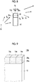
- the two rows of soundproof units 14a are arranged on the upper end surface of the partition member 12, but the present invention is not limited thereto.
- a soundproof structure 10b shown in Fig. 9 one row of soundproof units 14a may be provided on the upper end surface of the partition member 12.
- a configuration having three or more rows of soundproof units 14a may be adopted.
- a configuration having four or more rows of soundproof units 14a on the upper end surface of the partition member 12 may be adopted.
- the thickness of the soundproof unit 14a is set to a thickness approximately equal to the thickness of the partition member 12, but the present invention is not limited thereto. However, the thickness of the soundproof unit 14a and the thickness of the partition member 12 may be different.
- a configuration may be adopted in which the thickness of the soundproof unit 14a is smaller than the thickness of the partition member 12 as in a soundproof structure 10d shown in Figs. 13 and 14 .
- the main surface of the partition member 12 and the film surface of the film 24a of the soundproof unit 14b are even with each other, and the soundproof unit 14b is disposed on the partition member 12.
- the present invention is not limited thereto.
- a distance tl from one main surface of the partition member 12 to the soundproof unit 14b in the thickness direction is not limited, and the film surface of the film 24a of the soundproof unit 14b and the main surface of the partition member 12 may be even with each other or may not be even as long as the film surface of the film 24a of the soundproof unit 14b and the main surface of the partition member 12 are parallel.
- the thickness of the soundproof unit is approximately equal to the thickness of the partition member is preferable in that the installability of the soundproof unit is improved.
- the weight of the soundproof unit can be further reduced.
- the shape of the opening portion 22 of the soundproof unit 14b is an approximately square shape, but it is not limited thereto.
- a soundproof unit 14c in which a rectangular film 24b is vibratably fixed to a frame body 20c having a rectangular opening portion may be used.
- a through-hole 26 may be formed in a film 24c.
- a soundproof structure 10f shown in Fig. 19 has a configuration in which the soundproof unit 14d, which has the film 24c having the through-hole 26 formed therein, is arranged on the upper end surface of the partition member 12 similarly to the soundproof structure 10a shown in Fig. 3 .
- the soundproof unit 14d which has the film 24c having the through-hole 26 formed therein
- the partition member 12 similarly to the soundproof structure 10a shown in Fig. 3 .
- the size of the through-hole 26 is not limited, and may be set according to the size of a film 24 (the size of the opening portion 22 of the frame body 20). For example, for the film 24 having a size of 20 mm ⁇ , it is possible to provide the through-hole 26 of about ⁇ 3 mm.
- the soundproof unit used in the soundproof structure according to the embodiment of the present invention may have a configuration in which the film 24a is disposed on both surfaces of the opening portion 22 of the frame body 20a as in a soundproof unit 14e shown in Fig. 20 .
- a soundproof structure 10g shown in Fig. 21 has a configuration in which the soundproof unit 14e, which has the film 24a fixed to both surfaces of the frame body 20a, is arranged on the upper end surface of the partition member 12 similarly to the soundproof structure 10a shown in Fig. 3 .
- the soundproof unit used in the soundproof structure according to the embodiment of the present invention is not limited to the configuration in which the film 24a is vibratably fixed to the end surface of the frame body 20a, and a configuration may be adopted in which the film 24a is vibratably fixed in the opening portion 22 of the frame body 20a as in a soundproof unit 14f shown in Fig. 22 .
- the soundproof unit 14f is configured to have three films 24a, but the present invention is not limited thereto, and the soundproof unit 14f may be configured to have four or more films.
- a plurality of soundproof units having the same configuration are used.
- the present invention is not limited thereto, and a combination of soundproof units having different configurations may be used.
- Figs. 23 to 25 show examples of combining soundproof units having different configurations.
- a soundproof structure 10h shown in Fig. 23 has a soundproof unit 14a and a soundproof unit 14g.
- the soundproof unit 14a and soundproof unit 14g have the same configuration except that their sizes are different. That is, a frame body 20d (opening portion) and a film 24d of the soundproof unit 14g are smaller than the frame body 20a (opening portion) and the film 24a of the soundproof unit 14a.
- the soundproof structure 10h shown in Fig. 23 has a configuration in which the two rows of soundproof units 14a are arranged on the upper end surface of the partition member 12 and the two rows of soundproof units 14g are arranged on the plurality of arranged soundproof units 14a.
- a soundproof structure 10i shown in Fig. 24 has a configuration in which the two rows of soundproof units 14a shown in Fig. 5 are arranged on the upper end surface of the partition member 12 and the two rows of soundproof units 14d shown in Fig. 17 are arranged on the arranged soundproof units 14a.
- a soundproof structure 10j shown in Fig. 25 has a configuration in which the two rows of soundproof units 14a shown in Fig. 5 are arranged on the upper end surface of the partition member 12 and the two rows of soundproof units 14b shown in Fig. 11 are arranged on the arranged soundproof units 14a.
- the soundproof unit 14a is arranged on the upper end surface of the partition member 12.
- the soundproof unit may be disposed on the side surface of the partition member 12 or the soundproof unit may be disposed on the lower end surface of the partition member.
- the soundproof unit 14a may be arranged on each of the upper end surface and the lower end surface of the partition member 12 as in a soundproof structure 10k shown in Fig. 26 .
- the soundproof unit 14a may be arranged on the entire end surfaces of the partition member 12.
- the configuration in which the soundproof unit 14a is disposed on the end surface of the partition member 12 is not limited, and the soundproof unit 14a may be disposed in an opening portion serving as a window frame portion of a wall, an opening portion serving as a mounting portion of a door (door), or the like.
- two soundproof units (14g and 14h) may be arranged on the upper end surface of the partition member 12 so as to overlap each other in the thickness direction.
- a plurality of soundproof units may be arranged on the end surface of the partition member. However, it is sufficient that at least one soundproof unit is provided.
- the soundproof unit 14 a is disposed on the end surface of the partition member 12 with the film surface of the film 24a and the main surface of the partition member 12 parallel to each other.
- the present invention is not limited thereto, and the soundproof unit 14a may be disposed such that the film surface of the film 24a is inclined with respect to the main surface of the partition member 12.
- the inclination of the film surface of the film 24a with respect to the main surface of the partition member 12 in a case where a direction parallel to an end side where the main surface of the partition member 12 and the end surface, on which the soundproof unit 14a is disposed, are in contact with each other is set as a rotary axis is preferably -90° to 90°, more preferably -30° to 30°.
- a case where the value of the inclination is positive indicates that the film surface is inclined to the sound source side of the sound to be insulated, and a case where the value of the inclination is negative indicates that the film surface is inclined to a side opposite to the sound source.
- the inclination of the film surface of the film 24a with respect to the main surface of the partition member 12 in a case where a direction perpendicular to the end side where the main surface of the partition member 12 and the end surface, on which the soundproof unit 14a is disposed, are in contact with each other is set as a rotary axis is preferably -90° to 90°, more preferably -30° to 30°.
- the soundproof structures 10a to 101 are collectively referred to as a soundproof structure 10
- the soundproof units 14a to 14i are collectively referred to as a soundproof unit 14
- the frame bodies 20a to 20d are collectively referred to as a frame body 20
- the films 24a to 24d are collectively referred to as a film 24.
- the soundproof unit 14 has the frame body 20 having the opening portion 22 passing therethrough and the film 24 disposed so as to cover one of the opening surfaces of the opening portion 22, and the film 24 vibrates according to the sound incident on the film 24.
- the frame body 20 has one or more opening portions 22, and fixes the film 24 so as to cover the opening portion 22 so that the film 24 is vibratably supported.
- the frame body 20 has a closed continuous shape so as to be able to fix and restrain the entire circumference of the film 24.
- the present invention is not limited thereto, and the frame body 20 may be partially cut to have a discontinuous shape.
- the shape of the opening portion 22 of the frame body 20 is not particularly limited.
- the shape of the opening portion 22 of the frame body 20 may be a quadrangle such as a square, a rectangle, a diamond, or a parallelogram, a triangle such as an equilateral triangle, an isosceles triangle, or a right triangle, a polygon including a regular polygon such as a regular pentagon or a regular hexagon, a circle, an ellipse, and the like, or may be an irregular shape. End surfaces on both sides of the opening portion 22 of the frame body 20 are not blocked and are open to the outside as they are. That is, the opening portion 22 passes through the frame body 20.
- the size of the frame body 20 is a size in a plan view, and can be defined as the size of the opening portion 22. Accordingly, in the following description, the size of the frame body 20 is the size of the opening portion 22. However, in the case of a regular polygon such as a circle or a square, the size of the frame body 20 can be defined as a distance between opposite sides passing through the center or as a circle equivalent diameter. In the case of a polygon, an ellipse, or an irregular shape, the size of the frame body 20 can be defined as a circle equivalent diameter. In the present invention, the circle equivalent diameter and the radius are a diameter and a radius at the time of conversion into circles having the same area.
- the size of the opening portion 22 of the frame body 20 is not particularly limited, and may be appropriately set according to a soundproofing target to which the soundproof structure according to the embodiment of the present invention is applied for soundproofing.
- the size of the frame body 20 (opening portion) is preferably 0.5 mm to 200 mm, more preferably 1 mm to 100 mm, and most preferably 2 mm to 30 mm.
- the wall thickness and the thickness of the frame of the frame body 20 are not particularly limited as long as the film 24 can be reliably fixed so that the film 24 can be reliably supported.
- the wall thickness and the thickness of the frame of the frame body 20 can be set according to the size of the frame body 20.
- the wall thickness of the frame of the frame body 20 is preferably 0.5 mm to 20 mm, more preferably 0.7 mm to 10 mm, and most preferably 1 mm to 5 mm.
- the ratio of the wall thickness of the frame body 20 to the size of the frame body 20 is too large, the area ratio of the portion of the frame body 20 with respect to the entire structure increases. Accordingly, there is a concern that the device will become heavy. On the other hand, in a case where the ratio is too small, it is difficult to strongly fix the laminate with an adhesive or the like in the frame body 20 portion.
- the wall thickness of the frame body 20 is preferably 1 mm to 100 mm, more preferably 3 mm to 50 mm, and most preferably 5 mm to 20 mm.
- the thickness of the frame body 20, that is, the thickness of the opening portion 22 in the penetration direction is approximately equal to the thickness of the partition member 12.
- the thickness of the frame body 20, that is, the thickness of the opening portion 22 in the penetration direction is preferably 0.5 mm to 200 mm, more preferably 0.7 mm to 100 mm, and even more preferably 1 mm to 50 mm.
- the material of the frame body 20 is not particularly limited as long as the material can support the film 24, has a suitable strength, and is resistant to the soundproof environment of the soundproofing target, and can be selected according to the soundproofing target and the soundproof environment.
- metal materials such as aluminum, titanium, magnesium, tungsten, iron, steel, chromium, chromium molybdenum, nichrome molybdenum, and alloys thereof
- resin materials such as acrylic resins, polymethyl methacrylate, polycarbonate, polyamideimide, polyarylate, polyether imide, polyacetal, polyether ether ketone, polyphenylene sulfide, polysulfone, polyethylene terephthalate, polybutylene terephthalate, polyimide, and triacetyl cellulose, carbon fiber reinforced plastics (CFRP), carbon fiber, and glass fiber reinforced plastics (GFRP) can be mentioned.
- a plurality of materials of the frame body 20 may be used in combination.
- Examples of the material of the transparent frame body 20 include a transparent resin material, a transparent inorganic material, and the like.
- the transparent resin material include acetyl cellulose based resins such as triacetyl cellulose; polyester based resins such as polyethylene terephthalate (PET) and polyethylene naphthalate; olefin based resins such as polyethylene (PE), polymethylpentene, cycloolefin polymers, and cycloolefin copolymers; acrylic based resins such as polymethyl methacrylate; and polycarbonate.
- the transparent inorganic material include glass such as soda glass, potassium glass and lead glass; ceramics such as translucent piezoelectric ceramics (PLZT); quartz; and fluorite.
- an antireflection layer or the like may be given to the frame body 20. Accordingly, since the visibility can be made low (difficult to see), it is possible to improve the transparency.
- a known sound absorbing material may be disposed in the opening portion 22 of the frame body 20.
- the sound insulation characteristics can be more suitably adjusted by the sound absorption effect of the sound absorbing material.
- the sound absorbing material is not particularly limited, and various known sound absorbing materials, such as a urethane plate and a nonwoven fabric, can be used.
- the film 24 is fixed so as to be restrained by the frame body 20 so that the opening portion 22 of the frame body 20 is covered, and the film 24 absorbs or reflects the energy of sound waves to insulate sound by performing vibration vibrates corresponding to the sound waves from the outside. In addition, there is an effect of shifting the phase of the sound passing through the film vibration. Therefore, it is preferable that the film 24 is impermeable to air, that is, the film is formed of an air-impermeable material.
- the air-impermeable material is a material having a flow resistance per unit thickness of 1000000 (N ⁇ s/m 4 ) or more.
- the film 24 since the film 24 needs to vibrate with the frame body 20 as a node, it is necessary for the film 24 to be fixed to the frame body 20 so as to be reliably restrained by the frame body 20 and accordingly become an antinode of film vibration. For this reason, it is preferable that the film 24 is formed of a flexible viscoelastic material.
- the shape of the film 24 can be the shape of the opening portion 22 of the frame body 20.
- the size of the film 24 can be the size of the frame body 20, more specifically, the size of the opening portion 22 of the frame body 20.
- the film 24 fixed to the frame body 20 of the soundproof unit 14 has a first natural vibration frequency at which the transmission loss is the minimum, for example 0 dB, as a resonance frequency that is a frequency of the lowest order natural vibration mode.
- the first natural vibration frequency is determined by a structure configured to include the frame body 20 and the film 24. Therefore, the present inventors have found that approximately the same value as in a case where the through-hole 26 is not present is obtained even in a case where the through-hole 26 is perforated in the film 24 as in the soundproof unit 14d shown in Fig. 17 .
- the first natural vibration frequency of the film 24, which is fixed so as to be restrained by the frame body 20, in the structure configured to include the frame body 20 and the film 24 is a frequency of the natural vibration mode, in which sound waves are largely transmitted at the frequency in a case where the sound waves cause film vibration most due to the resonance phenomenon.
- the soundproofing effect is obtained by the effect of cancellation due to interference with the sound passing around the soundproof structure 10.
- the soundproofing effect due to cancellation of the phase-shifted sound in the vicinity of the first natural vibration frequency of the film 24 is increased.
- the first natural vibration frequency of the film 24 fixed so as to be restrained by the frame body 20 is preferably 20000 Hz or less, more preferably within the audible range (20 Hz to 20000 Hz), even more preferably in the range of 40 Hz to 16000 Hz, and particularly preferably in the range of 100 Hz to 12000 Hz.
- the soundproof structure 10 can selectively insulate sound in a predetermined frequency band having the first natural vibration frequency as a reference.
- the thickness and the material (Young's modulus) of the film 24, the size of the frame body 20 (opening portion 22), and the like may be appropriately set.
- the thickness of the film 24 is not particularly limited as long as the film 24 can vibrate.
- the thickness of the film 24 can be set according to the size of the frame body 20, that is, the size of the film.
- the thickness of the film 24 is preferably 0.005 mm (5 ⁇ m) to 5 mm, more preferably 0.007 mm (7 ⁇ m) to 2 mm, and most preferably 0.01 mm (10 ⁇ m) to 1 mm.
- the first natural vibration frequency of the film 24 in the soundproof unit 14 configured to include the frame body 20 and the film 24 can be determined by the geometric form of the frame body 20 of the soundproof unit 14, for example, the shape and size of the frame body 20 and the stiffness of the film 24 of the soundproof unit 14, for example, the thickness and the flexibility (Young's modulus) of the film 24.
- a ratio between the thickness (t) of the film 24 and the square of the size (a) of the frame body 20 can be used.
- a ratio [a 2 /t] between the size of one side and the square (t) of the size (a) of the frame body 20 can be used.
- the ratio [a 2 /t] is the same, for example, in a case where (t, a) is (50 ⁇ m, 7.5 mm) and a case where (t, a) is (200 ⁇ m, 15 mm)
- the first natural vibration mode is the same frequency, that is, the same first natural vibration frequency. That is, by setting the ratio [a 2 /t] to a predetermined value, the scale law is established. Accordingly, an appropriate size can be selected.
- the Young's modulus of the film 24 is not particularly limited as long as the film 24 has elasticity capable of causing the film vibration of the film 24.
- the Young's modulus of the film 24 can be set according to the size of the frame body 20, that is, the size of the film in the present invention.
- the Young's modulus of the film 24 is preferably 1000 Pa to 3000 GPa, more preferably 10000 Pa to 2000 GPa, and most preferably 1 MPa to 1000 GPa.
- the density of the film 24 is not particularly limited as long as the film can vibrate.
- the density of the film 24 is preferably 10 kg/m 3 to 30000 kg/ m 3 , more preferably 100 kg/m 3 to 20000 kg/m 3 , and most preferably 500 kg/m 3 to 10000 kg/m 3 .
- the material of the film 24 is not particularly limited as long as the material has a strength in the case of being applied to the above soundproofing target and is resistant to the soundproof environment of the soundproofing target so that the film 24 can vibrate, and can be selected according to the soundproofing target, the soundproof environment, and the like.
- Examples of the material of the film 24 include resin materials that can be made into a film shape such as polyethylene terephthalate (PET), polyimide, polymethylmethacrylate, polycarbonate, acrylic (PMMA), polyamideide, polyarylate, polyetherimide, polyacetal, polyetheretherketone, polyphenylene sulfide, polysulfone, polyethylene terephthalate, polybutylene terephthalate, polyimide, triacetyl cellulose, polyvinylidene chloride, low density polyethylene, high density polyethylene, aromatic polyamide, silicone resin, ethylene ethyl acrylate, vinyl acetate copolymer, polyethylene, chlorinated polyethylene, polyvinyl chloride, polymethyl pentene, and polybutene, metal materials that can be made into a foil shape such as aluminum, chromium, titanium, stainless steel, nickel, tin, niobium, tantalum, molybdenum, zirconium, gold, silver, platinum,
- the material of the transparent film 24 examples include a transparent resin material, a transparent inorganic material, and the like.
- the transparent resin material include acetyl cellulose based resins such as triacetyl cellulose; polyester based resins such as polyethylene terephthalate (PET) and polyethylene naphthalate; olefin based resins such as polyethylene (PE), polymethylpentene, cycloolefin polymers, and cycloolefin copolymers; acrylic based resins such as polymethyl methacrylate; and polycarbonate.
- PET polyethylene terephthalate
- olefin based resins such as polyethylene (PE), polymethylpentene, cycloolefin polymers, and cycloolefin copolymers
- acrylic based resins such as polymethyl methacrylate
- polycarbonate examples of the transparent resin material.
- an antireflection layer or the like may be given to the film 24. Accordingly, since the visibility can be made low (difficult to see), it is possible to improve the transparency.
- the method of fixing the film 24 to the frame body 20 is not particularly limited. Any method may be used as long as the film 24 can be fixed to the frame body 20 so as to serve as a node of film vibration. For example, a method using an adhesive, a method using a physical fixture, and the like can be mentioned.
- an adhesive 28 is applied onto the surface surrounding the opening portion 22 of the frame body 20 and the film 24 is placed thereon, so that the film 24 is fixed to the frame body 20 with the adhesive.
- the adhesive include epoxy based adhesives (Araldite and the like), cyanoacrylate based adhesives (Aron Alpha and the like), Super X (manufactured by Cemedine Co.), acrylic based adhesives, and the like.
- the film 24 may also be fixed to the frame body 20 using a double-sided tape.
- a method using a physical fixture a method can be mentioned in which the film 24 disposed so as to cover the opening portion 22 of the frame body 20 is interposed between the frame body 20 and a fixing member, such as a rod, and the fixing member is fixed to the frame body 20 by using a fixture, such as a screw.
- the film 24 may be tensioned and fixed, but it is preferable to fix the film 24 without tension.
- the end portion of the film 24 may be fixed. That is, a part may be a free end, and there may be a simple support portion without fixing.
- the end portion of the film 24 is in contact with the frame body 20. It is preferable that 50% or more of the end portion (peripheral portion) of the film 24 is fixed to the frame body 20, and it is more preferable that 90% or more is fixed to the frame body 20.
- the frame body 20 and the film 24 may be integrally formed of the same material.
- the configuration in which the frame body 20 and the film 24 are integrated can be manufactured by simple processing, such as compression molding, injection molding, imprinting, scraping processing, and a processing method using a three-dimensional shaping (3D) printer.
- simple processing such as compression molding, injection molding, imprinting, scraping processing, and a processing method using a three-dimensional shaping (3D) printer.
- the first natural vibration frequency of the film is f 1
- the sound speed in the air is c
- the opening end correction distance in a case where the cross-sectional shape of the opening portion is circular is approximately 0.61 ⁇ opening portion radius.
- the antinode of the standing wave of the sound field is located outside the opening portion by the distance of the opening end correction.
- the opening end correction distance can be calculated from the circle equivalent radius by regarding the cross-sectional shape as a circle having the same area.
- air column resonance occurs in opening portion 22 according to the thickness of the frame body 20 (thickness in the penetration direction of the opening portion 22). Since the sound in the vicinity of the resonance frequency of air column resonance in the opening portion 22 resonates in the opening portion 22, the sound pressure of the sound passing through the film increases in the vicinity of the resonance frequency of air column resonance. For this reason, in the vicinity of the resonance frequency of air column resonance, it is possible to appropriately obtain the effect of cancellation due to the phase difference between the sound passing through the space of the upper portion of the soundproof structure and the sound passing through the film. Therefore, even in a frequency band apart from the first natural vibration frequency of the film, the effect of cancellation due to the phase difference can be appropriately obtained by using the air column resonance of the opening portion 22.
- the resonance frequency of air column resonance is in the audible range, that is, from the viewpoint of insulating sounds in the audible range, it is preferable to satisfy the above-described Expression (1).
- Expression (2) From the viewpoint of insulating sounds with frequencies easy for human ears to hear (high sensitivity), it is preferable to satisfy Expression (2) or it is preferable to satisfy Expression (3).
- the film is preferably flame retardant.
- a resin for example, Lumirror (registered trademark) nonhalogen flame-retardant type ZV series (manufactured by Toray Industries, Inc.) that is a flame-retardant PET film, Teijin Tetoron (registered trademark) UF (manufactured by Teijin Ltd.), and/or Dialamy (registered trademark) (manufactured by Mitsubishi Plastics Co., Ltd.) that is a flame-retardant polyester film may be used.
- Lumirror registered trademark
- Teijin Tetoron registered trademark
- UF manufactured by Teijin Ltd.
- Dialamy registered trademark
- flame retardancy can be also given by using a metal material, such as aluminum.
- the frame body is also preferably a flame-retardant material.
- a metal such as aluminum, an inorganic material such as ceramic, a glass material, flame-retardant polycarbonate (for example, PCMUPY 610 (manufactured by Takiron Co., Ltd.)), and/or flame-retardant plastics such as flame-retardant acrylic (for example, Acrylite (registered trademark) FR1 (manufactured by Mitsubishi Rayon Co., Ltd.)) can be mentioned.
- a bonding method using a flame-retardant adhesive (Three Bond 1537 series (manufactured by Three Bond Co. Ltd.)) or solder or a mechanical fixing method, such as interposing a film between two frame bodies so as to be fixed therebetween, is preferable.
- the material forming the structural member is preferably a heat resistant material, particularly a material having low heat shrinkage.
- Teijin Tetoron (registered trademark) film SLA manufactured by Teijin DuPont Film
- PEN film Teonex registered trademark
- Lumirror registered trademark off-anneal low shrinkage type
- the frame body it is preferable to use heat resistant plastics, such as polyimide resin (TECASINT 4111 (manufactured by Enzinger Japan Co., Ltd.)) and/or glass fiber reinforced resin (TECAPEEKGF 30 (manufactured by Enzinger Japan Co., Ltd.)) and/or to use a metal such as aluminum, an inorganic material such as ceramic, or a glass material.
- TECASINT 4111 manufactured by Enzinger Japan Co., Ltd.
- TECAPEEKGF 30 glass fiber reinforced resin
- a metal such as aluminum, an inorganic material such as ceramic, or a glass material.
- the adhesive it is preferable to use a heat resistant adhesive (TB 3732 (Three Bond Co., Ltd.), super heat resistant one component shrinkable RTV silicone adhesive sealing material (manufactured by Momentive Performance Materials Japan Ltd.) and/or heat resistant inorganic adhesive Aron Ceramic (registered trademark) (manufactured by Toagosei Co., Ltd.)).
- TB 3732 Three Bond Co., Ltd.
- super heat resistant one component shrinkable RTV silicone adhesive sealing material manufactured by Momentive Performance Materials Japan Ltd.
- heat resistant inorganic adhesive Aron Ceramic registered trademark
- the weather resistance of the structural member becomes a problem.
- a weather-resistant film such as a special polyolefin film (ARTPLY (registered trademark) (manufactured by Mitsubishi Plastics Inc.)), an acrylic resin film (ACRYPRENE (manufactured by Mitsubishi Rayon Co.)), and/or Scotch Calfilm (trademark) (manufactured by 3M Co.).
- ARTPLY registered trademark
- ACRYPRENE manufactured by Mitsubishi Rayon Co.
- Scotch Calfilm trademark
- plastics having high weather resistance such as polyvinyl chloride, polymethyl methacryl (acryl), metal such as aluminum, inorganic materials such as ceramics, and/or glass materials.
- epoxy resin based adhesives and/or highly weather-resistant adhesives such as Dry Flex (manufactured by Repair Care International).
- moisture resistance it is preferable to appropriately select a film, a frame body, and an adhesive having high moisture resistance.
- an appropriate film, frame body, and adhesive it is preferable to appropriately select an appropriate film, frame body, and adhesive.
- dust may adhere to the film surface to affect the soundproofing characteristics of the soundproof structure according to the embodiment of the present invention. Therefore, it is preferable to prevent the adhesion of dust or to remove adhering dust.
- a film formed of a material to which dust is hard to adhere As a method of preventing dust, it is preferable to use a film formed of a material to which dust is hard to adhere. For example, by using a conductive film (Flecria (registered trademark) (manufactured by TDK Corporation) and/or NCF (Nagaoka Sangyou Co., Ltd.)) so that the film is not charged, it is possible to prevent adhesion of dust due to charging.
- a conductive film Fecria (registered trademark) (manufactured by TDK Corporation) and/or NCF (Nagaoka Sangyou Co., Ltd.)
- a cover it is possible to use a thin film material (Saran Wrap (registered trademark) or the like), a mesh having a mesh size not allowing dust to pass therethrough, a nonwoven fabric, a urethane, an airgel, a porous film, and the like.
- Saran Wrap registered trademark
- the film may be pressed to change the resonance frequency. Therefore, by covering the film with a nonwoven fabric, urethane, and/or a film, the influence of wind can be suppressed. Similarly to the above-described case of dust, it is preferable to provide a cover on the film so that wind does not hit the film directly.
- a plurality of frame bodies may be formed by one continuous frame body.
- a plurality of soundproof units may be provided with an individual soundproof unit as a unit.
- a Magic Tape registered trademark
- a magnet a button, a suction cup, and/or an uneven portion
- a tape or the like As a method of connecting a plurality of soundproof units in a case where a plurality of soundproof units are provided as units, a Magic Tape (registered trademark), a magnet, a button, a suction cup, and/or an uneven portion may be attached to a frame body so as to be combined therewith, or a plurality of soundproof units can be connected using a tape or the like.
- an attachment and detachment mechanism formed of a magnetic material, a Magic Tape (registered trademark), a button, a suction cup, and/or an uneven portion is preferably attached to the end surfaces of the soundproof unit and the partition member.
- the soundproof unit since the soundproof unit is disposed on the end surface of the partition member, it is preferable that the soundproof unit (frame body) is lightweight. In a case where the weight is reduced simply by making the frame of the frame body thin, the stiffness of the frame body is reduced so that the frame body itself easily vibrates. As a result, a function as a fixed end is degraded.
- the soundproof structure according to the embodiment of the present invention is used for soundproof walls on highways, general roads, railroad tracks, and the like, doors and walls of buildings, doors of toilets, partitions used in offices and conference rooms, and the like.
- the soundproof structure on the porch or providing the soundproof structure between the counter kitchen and the living room, silence can be realized in the living space where silence is required.
- an acrylic frame body having a size of the opening portion 22 of 40 mm ⁇ , a frame width of 5 mm, and a frame thickness of 20 mm was manufactured.
- a PET film (Lumirror; manufactured by Toray Industries, Inc.) having a thickness of 50 ⁇ m was attached to the opening surface of the frame body 20 with a double-sided tape (Scotch manufactured by 3M Co., Ltd.) to manufacture the soundproof unit 14 shown in Fig. 13 .
- the first natural vibration frequency of the film 24 of the soundproof unit 14 was measured, and was lower than 100 Hz.
- a plate-shaped member having a thickness of 50 mm and a width of 0.350 m and formed of a material of stainless steel was used as the partition member 12.
- two soundproof units 14 were disposed in the height direction and seven soundproof units 14 were disposed in the width direction to manufacture the soundproof structure 10 shown in Fig. 13 .
- the height of the soundproof structure 10 including the soundproof unit 14 was 0.5 m.
- a soundproof structure was manufactured in the same manner as in Example 1-1 except that the thickness of the film was set to 125 ⁇ m.
- the first natural vibration frequency of the film of the soundproof unit was 250 Hz.
- a soundproof structure was manufactured in the same manner as in Example 1-1 except that the thickness of the film was set to 250 ⁇ m.
- the first natural vibration frequency of the film of the soundproof unit was 500 Hz.
- a soundproof structure was manufactured in the same manner as in Example 1-1 except that there was no soundproof unit. That is, a single partition member is referred to as Comparative example 1-1. Therefore, the height of the partition member was 0.5 m.
- a soundproof structure was manufactured in the same manner as in Example 1-1 except that there was no film, as in a soundproof structure 106 shown in Fig. 36 .
- the soundproof structure 106 shown in Fig. 36 has a configuration in which the frame bodies 20b are arranged on the upper end surface of the partition member 12.
- a soundproof structure was manufactured in the same manner as in Example 1-1 except that a soundproof unit 110, in which the opening portion of the frame body 20 is small and the first natural vibration frequency of the film 24 is outside the audible range, is used, as in a soundproof structure 108 shown in Fig. 37 .
- the size of the opening portion of the frame body 20 is 2 mm and the frame width is 1 mm.
- 40 soundproof units 110 are disposed in the height direction and 140 soundproof units 110 are disposed in the width direction.
- the first natural vibration frequency of the film 24 of the soundproof unit 110 was over 20000 Hz.
- a soundproof structure was manufactured in the same manner as in Comparative example 1-3 except that the material of the film was stainless steel and the thickness was 1000 ⁇ m.
- the film can be regarded as a rigid body and does not vibrate.
- the soundproofing effect was evaluated by calculating the insertion loss difference in a case where each soundproof structure was used.
- a measurement space surrounded by an acrylic floor F, a wall surface W on which a sound absorbing body formed of urethane was entirely provided, and a ceiling C on which a sound absorbing body formed of urethane was entirely provided was prepared.
- the height of the measurement space was 1 m
- the depth (length in the horizontal direction in the diagram) was 1.5 m
- the width (length in a direction perpendicular to the paper surface) was 0.350 m.
- a speaker Q (FE103En, manufactured by FOSTEX Co., Ltd.) was disposed as a sound source on the floor F on one side of the wall W at the center in the width direction of the measurement space, and the soundproof structure 10 was provided at a position 0.5 m away from the speaker Q in the depth direction. Assuming that a region of 0.25 m ⁇ 0.25 m on the surface side of the soundproof structure 10 opposite to the speaker Q is a measurement region R, 5 ⁇ 5 microphones M (type 4160N, manufactured by Accor, Inc.) were provided at a distance of 41.7 mm in the measurement region R, and the sound pressure in the measurement region R was measured by the microphones M.
- Table 1 shows the insertion loss difference at 1600 Hz.
- Table 1 Configuration of soundproof unit Frame body Film Insertion loss difference @ 1600Hz dB Opening portion size Thickness mm Material Thickness ⁇ m First natural vibration frequency Hz
- Example 1-1 Frame body + film 40mm ⁇ 20 PET 50 Lower than 100 18.5
- Example 1-2 Frame body + film 40mm ⁇ 20 PET 125 250 4.3
- Example 1-3 Frame body + film 40mm ⁇ 20 PET 250 500 0.4
- Comparative Example 1-1 None - - - - - - 0
- a soundproof structure 10 was manufactured in the same manner as in Example 1-2 except that the thickness of the frame body 20 was set to 50 mm, and the insertion loss difference was measured.
- a soundproof structure 10 was manufactured in the same manner as in Example 1-4 except that the material and the thickness of the film were changed as shown in Table 2, and the insertion loss difference was measured.
- a soundproof structure was manufactured in the same manner as in Example 1-4 except that the material of the film was polyimide and the thickness of the film was 100 ⁇ m.
- the first natural vibration frequency of the film of the soundproof unit was 200 Hz.
- a soundproof structure was manufactured in the same manner as in Example 1-10 except that the thickness of the film was set to 200 ⁇ m.
- the first natural vibration frequency of the film of the soundproof unit was 340 Hz.
- Table 3 shows the insertion loss difference at 2000 Hz.
- a soundproof structure was manufactured in the same manner as in Example 1-1 except that, instead of the soundproof unit, Glass Wool (GW64 manufactured by Asahi Glass Fiber Co., Ltd., thickness: 50 mm) as a fibrous porous sound absorbing material was disposed on the upper end surface of the partition member, and the insertion loss difference was measured.
- Glass Wool GW64 manufactured by Asahi Glass Fiber Co., Ltd., thickness: 50 mm
- Fig. 29 is a graph showing the relationship between the insertion loss difference and the frequency in Example 1-1 and Comparative example 1-5.
- Example 1-1 of the present invention has a higher soundproofing effect in a broad band than in the conventional structure.
- a soundproof structure 10 was manufactured in the same manner as in Example 1-1 except that the number of soundproof units 14 in the height direction was set to 1 and 4, and the insertion loss difference was measured.
- Example 1-1 Frame body + film 2 40mm ⁇ 20 P ET 50 Lower than 100 18.5
- Example 2-1 Frame body + film 1 40mm ⁇ 20 PET 50 Lower than 100 5.3
- Example 2-2 Frame body + film 4 40mm ⁇ 20 PET 50 Lower than 100 6.3
- the insertion loss difference ⁇ L is higher than that in a case where there is one soundproof unit and accordingly the soundproofing effect is high.
- a soundproof structure 10 was manufactured in the same manner as in Example 1-5 except that the soundproof unit 14 shown in Fig. 20 having a configuration in which the film 24 was fixed to both surfaces of the frame body 20 was used as the soundproof unit 14, and the insertion loss difference was measured.
- the insertion loss difference at a frequency of 2000 Hz was 5.3. Therefore, it can be seen that the soundproofing effect is high.
- a soundproof structure 10 was manufactured in the same manner as in Example 1-1 except that the through-hole 26 having a diameter shown in Table 5 was formed at the center of the film 24, and the insertion loss difference was measured.
- a soundproof structure 10 was manufactured in the same manner as in Example 2-2 except that the height of the partition member 12 was increased to set the height of the soundproof structure 10 including the soundproof unit 14 to 1 m, and the insertion loss was measured.
- the height of the measurement space at the time of measuring the insertion loss was set to 2 m, and the size of the measurement region was set to 0.5 m ⁇ 0.5 m.
- the insertion loss difference ⁇ L was calculated as a difference from the insertion loss in Comparative example 5-1.
- a soundproof structure was manufactured in the same manner as in Example 5-1 except that the height of the partition member was set to 1 m by providing no soundproof unit 14, and the insertion loss was measured.
- a soundproof structure 10 was manufactured in the same manner as in Example 2-2 except that the height of the partition member 12 was increased to set the height of the soundproof structure 10 including the soundproof unit 14 to 2 m, and the insertion loss was measured.
- the height of the measurement space at the time of measuring the insertion loss was set to 3 m, the distance from the sound source was set to 1 m, and the size of the measurement region was set to 1.5 m ⁇ 1.5 m.
- the insertion loss difference ⁇ L was calculated as a difference from the insertion loss in Comparative example 5-2.
- a soundproof structure was manufactured in the same manner as in Example 5-2 except that the height of the partition member was set to 2 m by providing no soundproof unit 14, and the insertion loss was measured.
- a soundproof structure was manufactured in the same manner as in Example 1-1 except that the soundproof unit 14 was disposed by inclining the film surface of the film 24 by -30° with respect to the main surface of the partition member 12 (refer to Fig. 42 ), the insertion loss was measured, and the insertion loss difference from Comparative example 1-1 was measured.
- a soundproof structure was manufactured in the same manner as in Example 1-1 except that the soundproof unit 14 was disposed by inclining the film surface of the film 24 by 30° with respect to the main surface of the partition member 12 (refer to Fig. 43 ), the insertion loss was measured, and the insertion loss difference was calculated.
- the above-described examples and comparative examples were reproduced and the sound pressure distribution was obtained by calculation.
- the floor F and the partition member 12 were set as rigid walls.
- the wall surface W and the ceiling C were set as perfect matched layers (PML layer) with no sound reflection, and the four sides of the film were set as fixed ends.
- the frame body was a rigid body. A periodic boundary condition continuing infinitely in the width direction was adopted.
- ) log is a common logarithm
- Fig. 30 shows a sound pressure distribution in a case where no soundproof structure is provided.
- Fig. 31 shows a sound pressure distribution in the case of Comparative example 1-1.
- Fig. 32 shows a sound pressure distribution in the case of Comparative example 1-5.
- Fig. 33 shows a sound pressure distribution in the case of Example 1-1.
- Fig. 34 shows a sound pressure distribution in the case of Example 1-8.
- Fig. 35 shows a sound pressure distribution in the case of Example 4-3.
- Fig. 38 shows a sound pressure distribution in the case of Comparative example 5-1.
- Fig. 39 shows a sound pressure distribution in the case of Example 5-1.
- Fig. 40 shows a sound pressure distribution in the case of Comparative example 5-2.
- Fig. 41 shows a sound pressure distribution in the case of Example 5-2.
- Fig. 42 shows a sound pressure distribution in the case of Example 6-1.
- Fig. 43 shows a sound pressure distribution in the case of Example 6-2.
- These sound pressure distributions are sound pressure distributions at a frequency of 1600 Hz except for Examples 6-1 and 6-2, and the sound pressure distributions in Examples 6-1 and 6-2 are sound pressure distributions at a frequency of 2200 Hz.
- Example 1-1 Simulation was performed in the same manner as described above and in the same manner as Example 1-1 except that the film 24 was a PET film having a thickness of 188 ⁇ m, the size of the opening portion 22 of the frame body 20 was 20 mm ⁇ , and the thickness of the frame body 20 was set to 10 mm, 30 mm, 50 mm, 75 mm, and 100 mm.
- the first natural vibration frequency of the film 24 fixed to the frame body 20 of 20 mmD was 1520 Hz.
- the sound pressure in the measurement region R was calculated and the insertion loss was calculated, and the insertion loss difference ⁇ L with respect to the insertion loss in the case of a single partition member was calculated.
- a higher insertion loss difference can be obtained in a frequency band of 2000 Hz or less in a case where c/(4La) is 2000 or less.
- a higher insertion loss difference can be obtained in a frequency band equal to or lower than the first natural vibration frequency of the film.
Abstract
Description
- The present invention relates to a soundproof structure.
- Partition members, such as partitions, doors, and walls of rooms (buildings), or soundproof walls provided on highways, general roads, railroad tracks, and the like, are used for soundproofing. In such partition members used for soundproofing, due to the "diffraction phenomenon" in which the sound leaks from the upper portion or lateral portion of each partition member, there is a problem that a sufficient soundproofing effect cannot be obtained even in a case where the partition member is provided. In order to obtain a sufficient soundproofing effect, it is necessary to increase the height of the partition member.
- In order to solve the diffraction phenomenon, it is considered to enhance the soundproofing effect by providing a sound absorbing material at the upper end portion of a plate member (partition member) to suppress the diffraction of the sound (
JP5380610B - However, in a case where a sound absorbing body formed of a porous body is provided at the upper end portion of the partition member (plate member), the sound incident on the sound absorbing body is absorbed, but the sound passing through the upper portion of the sound absorbing body causes a diffraction phenomenon without being absorbed. Therefore, in the configuration in which the sound absorbing material that is a porous body is disposed at the upper end portion of the partition member, the soundproofing effect is not sufficient.
- It is an object of the present invention to provide a soundproof structure capable of obtaining a sufficient soundproofing effect by suppressing the leaking of sound due to a diffraction phenomenon in a partition member used for soundproofing by solving the above-described problems of the conventional technique.
- In order to achieve the aforementioned object, the present inventors have made intensive studies and as a result, have found that the above-described problems can be solved in such a manner that there are provided a soundproof unit having a frame body, which has an opening portion, and a film, which is disposed so as to cover the opening portion and vibrates according to the sound incident on the film, and a partition member to which one or more soundproof units are attached, thereby completing the present invention.
- That is, it has been found that the aforementioned object can be achieved by the following configurations.
- [1] A soundproof structure comprising: a soundproof unit that has a frame body, which has an opening portion, and a film, which is disposed so as to cover the opening portion and vibrates according to a sound incident on the film; and a partition member to which one or more soundproof units are attached.
- [2] The soundproof structure described in [1], where, assuming that a total length of a thickness of the frame body in a penetration direction of the opening portion and an opening end correction distance is La and a sound speed in air is c, a relationship of c/(4La) ≤ 20000 is satisfied.
- [3] The soundproof structure described in [2], where, assuming that a total length of a thickness of the frame body in a penetration direction of the opening portion and an opening end correction distance is La and a sound speed in air is c, a relationship of c/(4La) ≤ 2000 is satisfied.
- [4] The soundproof structure described in [1], where, assuming that a total length of a thickness of the frame body in a penetration direction of the opening portion and an opening end correction distance is La, a first natural vibration frequency of the film is f1, and a sound speed in air is c, a relationship of c/(4La) ≤ f1 is satisfied.
- [5] The soundproof structure described in any one of [1] to [4], where the soundproof unit is attached to an end surface of the partition member.
- [6] The soundproof structure described in [5], where the soundproof unit is attached to the end surface of the partition member such that a film surface of the film is parallel to a main surface of the partition member.
- [7] The soundproof structure described in any one of [1] to [6], where the film is formed of an air-impermeable material.
- [8] The soundproof structure described in any one of [1] to [7], where a first natural vibration frequency of the film of the soundproof unit is 20000 Hz or less.
- [9] The soundproof structure described in any one of [1] to [8], where the first natural vibration frequency of the film of the soundproof unit is within an audible range.
- [10] The soundproof structure described in any one of [1] to [9], where two or more soundproof units are arranged on an end surface of the partition member.
- [11] The soundproof structure described in any one of [1] to [10], where the film of the soundproof unit has a through-hole.
- [12] The soundproof structure described in any one of [1] to [11], where the frame body and the film of the soundproof unit are transparent.
- [13] The soundproof structure described in any one of [1] to [12], where the soundproof unit has at least one of an attachable and detachable portion with respect to the partition member or an attachable and detachable portion with respect to another soundproof unit.
- According to the present invention, it is possible to provide a soundproof structure capable of obtaining a sufficient soundproofing effect by suppressing the leaking of sound due to a diffraction phenomenon in a partition member used for soundproofing.
-
-
Fig. 1 is a front view schematically showing an example of a soundproof structure of the present invention. -
Fig. 2 is a side view of the soundproof structure shown inFig. 1 . -
Fig. 3 is a partially enlarged perspective view of the soundproof structure shown inFig. 1 . -
Fig. 4 is a partially enlarged side view of the soundproof structure shown inFig. 1 . -
Fig. 5 is a perspective view schematically showing a soundproof unit of the soundproof structure shown inFig. 1 . -
Fig. 6 is a side view of the soundproof unit shown inFig. 5 . -
Fig. 7 is a diagram conceptually showing the propagation of sound waves in the case of a conventional soundproof structure. -
Fig. 8 is a diagram conceptually showing the propagation of sound waves in the case of the soundproof structure of the present invention. -
Fig. 9 is a partially enlarged perspective view schematically showing another example of the soundproof structure of the present invention. -
Fig. 10 is a partially enlarged perspective view schematically showing another example of the soundproof structure of the present invention. -
Fig. 11 is a perspective view schematically showing another example of the soundproof unit used in the soundproof structure of the present invention. -
Fig. 12 is a side view of the soundproof unit shown inFig. 11 . -
Fig. 13 is a partially enlarged perspective view schematically showing another example of the soundproof structure of the present invention. -
Fig. 14 is a partially enlarged side view of the soundproof structure shown inFig. 13 . -
Fig. 15 is a partially enlarged perspective view schematically showing another example of the soundproof structure of the present invention. -
Fig. 16 is a partially enlarged side view of the soundproof structure shown inFig. 15 . -
Fig. 17 is a perspective view schematically showing another example of the soundproof unit used in the soundproof structure of the present invention. -
Fig. 18 is a side view of the soundproof unit shown inFig. 17 . -
Fig. 19 is a partially enlarged perspective view schematically showing another example of the soundproof structure of the present invention. -
Fig. 20 is a perspective view schematically showing another example of the soundproof unit used in the soundproof structure of the present invention. -
Fig. 21 is a partially enlarged perspective view schematically showing another example of the soundproof structure of the present invention. -
Fig. 22 is a perspective view schematically showing another example of the soundproof unit used in the soundproof structure of the present invention. -
Fig. 23 is a partially enlarged perspective view schematically showing another example of the soundproof structure of the present invention. -
Fig. 24 is a partially enlarged perspective view schematically showing another example of the soundproof structure of the present invention. -
Fig. 25 is a partially enlarged perspective view schematically showing another example of the soundproof structure of the present invention. -
Fig. 26 is a side view schematically showing another example of the soundproof structure of the present invention. -
Fig. 27 is a side view schematically showing another example of the soundproof structure of the present invention. -
Fig. 28 is a diagram illustrating a method of measuring the sound pressure distribution. -
Fig. 29 is a graph showing the relationship between the frequency and the insertion loss difference. -
Fig. 30 is a diagram showing the calculation result of sound pressure distribution. -
Fig. 31 is a diagram showing the calculation result of sound pressure distribution. -
Fig. 32 is a diagram showing the calculation result of sound pressure distribution. -
Fig. 33 is a diagram showing the calculation result of sound pressure distribution. -
Fig. 34 is a diagram showing the calculation result of sound pressure distribution. -
Fig. 35 is a diagram showing the calculation result of sound pressure distribution. -
Fig. 36 is a partially enlarged perspective view showing a soundproof structure of a comparative example. -
Fig. 37 is a partially enlarged perspective view showing a soundproof structure of a comparative example. -
Fig. 38 is a diagram showing the calculation result of sound pressure distribution. -
Fig. 39 is a diagram showing the calculation result of sound pressure distribution. -
Fig. 40 is a diagram showing the calculation result of sound pressure distribution. -
Fig. 41 is a diagram showing the calculation result of sound pressure distribution. -
Fig. 42 is a diagram showing the calculation result of sound pressure distribution. -
Fig. 43 is a diagram showing the calculation result of sound pressure distribution. -
Fig. 44 is a graph showing the relationship between the frequency and the insertion loss difference. - Hereinafter, the present invention will be described in detail.
- The description of constituent elements described below may be made based on representative embodiments of the present invention, but the present invention is not limited to such embodiments.
- The numerical range expressed by using "∼" in this specification means a range including numerical values described before and after "∼" as a lower limit and an upper limit.
- In this specification, it is assumed that the terms "perpendicular" and "parallel" include the range of error accepted in the technical field to which the present invention belongs. For example, "perpendicular" and "parallel" mean within a range less than ±10° with respect to strictly perpendicular or parallel. The error with respect to strictly perpendicular or parallel is preferably 5° or less, more preferably 3° or less.
- In addition, it is assumed that an angle expressed by something other than "perpendicular" and "parallel", for example, a specific angle such as 15° or 45°, includes a range of error allowed in the technical field to which the present invention belongs. For example, in the present invention, the angle means being less than ±5° with respect to the strictly specified angle, and the error with respect to the shown strict angle is preferably ±3° or less, and more preferably ±1° or less.
- A soundproof structure according to an embodiment of the present invention is a soundproof structure having a soundproof unit having a frame body, which has an opening portion, and a film, which is disposed so as to cover the opening portion and vibrates according to the sound incident on the film, and a partition member to which one or more soundproof units are attached.
- The configuration of the soundproof structure according to the embodiment of the present invention will be described with reference to
Figs. 1 to 6 . -
Fig. 1 is a schematic front view showing an example of a preferred embodiment of the soundproof structure of the present invention,Fig. 2 is a side view of the soundproof structure shown inFig. 1 ,Fig. 3 is a partially enlarged perspective view of the soundproof structure shown inFig. 1 , andFig. 4 is a partially enlarged side view of the soundproof structure shown inFig. 1 .Fig. 5 is a schematic perspective view showing one ofsoundproof units 14a forming the soundproof structure shown inFig. 1 , andFig. 6 is a side view of thesoundproof unit 14a shown inFig. 5 . - A
soundproof structure 10a shown inFigs. 1 to 4 has a plate-shapedpartition member 12 and a plurality ofsoundproof units 14a arranged on the upper end surface (end surface on the upper side in the vertical direction in the diagrams) of thepartition member 12. - In the example shown in
Fig. 1 , eightsoundproof units 14a are disposed in the width direction on the upper end surface of thepartition member 12, and thesoundproof unit 14a is further disposed on eachsoundproof unit 14a. That is, thesoundproof structure 10a has thepartition member 12 and (8 × 2)soundproof units 14a arranged on the upper end surface of thepartition member 12. - As shown in
Figs. 5 and 6 , thesoundproof unit 14a has aframe body 20a having an openingportion 22 passing therethrough and afilm 24a disposed so as to cover one of the opening surfaces of the openingportion 22, and thefilm 24a vibrates according to the sound incident on thefilm 24a. - As shown in
Figs. 3 and 4 , in thesoundproof structure 10a, the thickness of thesoundproof unit 14a in the penetration direction of the opening portion 22 (hereinafter, simply referred to as the thickness of the soundproof unit) is approximately equal to the thickness of thepartition member 12. - In the shown example, all of the plurality of
soundproof units 14a are disposed such that the film surface of thefilm 24a is parallel to the main surface (maximum surface) of thepartition member 12 and the film surface of thefilm 24a and the main surface of thepartition member 12 are even with each other. The plurality ofsoundproof units 14a are disposed with thefilms 24a facing the same direction so that the film surfaces of therespective films 24a are on the same surface. - The main surface of the
partition member 12 is a maximum surface, and a surface whose normal vector faces the partitioned space in a case where the soundproof structure is provided at a target place. - The
partition member 12 refers to a member, a wall, and the like separating two spaces from each other. Examples of thepartition member 12 are various known plate-shaped members used for soundproofing, such as a fixed wall forming a building structure such as a house, a building, and a factory, a fixed wall such as a fixed partition disposed in a room of a building to partition the inside of the room, a movable wall such as a movable partition disposed in a room of a building to partition the inside of the room, doors, windows, and window frames of buildings, and soundproof walls provided on highways, general roads, and railroad tracks. - The material of the
partition member 12 may be selected according to the application, desired function, and the like, and various metals, resins such as acrylic, glass, concrete, mortar, wood, and the like can be appropriately used. - The size of the
partition member 12 is not limited, and may be appropriately set according to the application, desired function, and the like. - As described above, in such partition members used for soundproofing, due to the "diffraction phenomenon" in which the sound leaks from the upper portion or lateral portion of each partition member, there is a problem that sufficient soundproofing effect cannot be obtained even in a case where the partition member is provided.
- Specifically, as shown in
Fig. 7 , a sound S0 directed to apartition member 100 among sounds S0 generated from a sound source Q is blocked by thepartition member 100 and does not reach the back side of thepartition member 100, but a sound S1 passing through the upper portion of thepartition member 100 leaks to the back side of thepartition member 100 by the diffraction phenomenon as indicated by sound S2. For this reason, a sufficient soundproofing effect cannot be obtained. Therefore, in order to obtain a sufficient soundproofing effect, it is necessary to increase the height of the partition member. - In order to solve the diffraction phenomenon, it is considered to enhance the soundproofing effect by providing a sound absorbing material formed of a porous body at the upper end portion of the partition member to suppress the diffraction of the sound. However, in a case where a sound absorbing body formed of a porous body is provided at the upper end portion of the partition member, the sound incident on the sound absorbing body is absorbed, but the sound passing through the upper portion of the sound absorbing body causes a diffraction phenomenon without being absorbed. Therefore, in the configuration in which the sound absorbing material that is a porous body is disposed at the upper end portion of the partition member, the soundproofing effect is not sufficient.
- In contrast, the
soundproof structure 10a according to the embodiment of the present invention has a configuration in which a plurality ofsoundproof units 14a, each of which has theframe body 20a having the openingportion 22 and thefilm 24a disposed so as to cover theopening portion 22, are arranged on the upper end surface of thepartition member 12. - The
soundproof unit 14a absorbs the incident sound by the film vibration of thefilm 24a to show the soundproofing effect, but a part of the incident sound passes through thefilm 24a. In other words, the sound pressure of the sound passing through thefilm 24a (film vibration) decreases. In addition, the phase of the sound passing through the film changes. - Therefore, as shown in
Fig. 8 , in thesoundproof structure 10a, among sounds S0 generated from the sound source Q, a sound S1 passing through the upper portion of thesoundproof structure 10a and a sound S3 passing through the film vibration of thefilm 24a of thesoundproof unit 14a have different phases. For this reason, since the sound S1 and the sound S3 interfere with each other to become weak (canceled out), the sound leaking to the back side of thesoundproof structure 10a is reduced due to the diffraction phenomenon as indicated by sound S4. - As described above, using the fact that the phase of the sound passing through the soundproof unit changes, the soundproof structure according to the embodiment of the present invention insulates sound by cancellation due to the phase difference between the sound passing through the space of the upper portion of the soundproof structure and the sound passing through the soundproof unit provided in the soundproof structure. Therefore, a higher soundproofing effect can be obtained with a smaller area than in the configuration in which a sound absorbing material formed of a porous body is provided in a partition member.
- In the soundproof unit, since sounds in the vicinity of the resonance frequency of the film vibration of the film are likely to pass through the film, an effect of cancellation due to the phase difference can be obtained in the vicinity of the resonance frequency of the film of the soundproof unit. In addition, sounds not in the vicinity of the resonance frequency are difficult to pass through the film (that is, the sound pressure of the transmitted sound decreases), but the amount of change in the phase increases. For this reason, the effect of cancellation due to the phase difference is obtained. Therefore, desired sound can be selectively insulated by appropriately setting the resonance frequency of the film of the soundproof unit.
- In addition, since the soundproof unit can be formed by only a film that vibrates and a frame body that fixes the film, the inside of the frame body can be made hollow. Therefore, the soundproof unit can be made very lightweight.
- Since porous bodies themselves generally used as sound absorbing materials, such as urethane, glass wool and rock wool, are opaque, the landscape or the design may be damaged depending on the place to be used.
- In contrast, since the soundproof unit used in the soundproof structure according to the embodiment of the present invention is configured to include the film and the frame body, the soundproof unit can be made to have light transparency by using a transparent member as a material for forming the film and the frame body. This can prevent damage to the landscape and the design.
- In addition, since the soundproof unit is transparent, it is possible to guide light from the outside into the space partitioned by the soundproof structure. Therefore, it is possible to secure brightness and a field of view. In addition, by making a person not feel the size, it is possible to reduce the sense of oppression.
- Here, in the present invention, the transparent member is a member having a transmittance of 80% or more of light having a wavelength of 380 nm to 780 nm.
- In the present invention, the transmittance may be measured according to the method of measuring the total light transmittance in JIS K 7375 "Method for calculating total light transmittance and total light reflectivity of plastics".
- Since the soundproof unit used in the soundproof structure according to the embodiment of the present invention is configured to include the film and the frame body, it is possible to select a material having a desired color as a material for forming the film and the frame body or easily perform coloring. For example, by making the color of the material for forming the film and the frame body similar to the color of the partition member, it is possible to prevent damage to the landscape and the design.
- In addition, since the soundproof structure according to the embodiment of the present invention shows its effect only by providing the soundproof unit in the partition member, it is possible to easily provide the soundproof unit later in the partition member, such as a known soundproof wall and partition.
- In the example shown in
Fig. 3 , the two rows ofsoundproof units 14a are arranged on the upper end surface of thepartition member 12, but the present invention is not limited thereto. As in asoundproof structure 10b shown inFig. 9 , one row ofsoundproof units 14a may be provided on the upper end surface of thepartition member 12. Alternatively, a configuration having three or more rows ofsoundproof units 14a may be adopted. For example, as in asoundproof structure 10c shown inFig. 10 , a configuration having four or more rows ofsoundproof units 14a on the upper end surface of thepartition member 12 may be adopted. - In the example shown in
Fig. 3 , the thickness of thesoundproof unit 14a is set to a thickness approximately equal to the thickness of thepartition member 12, but the present invention is not limited thereto. However, the thickness of thesoundproof unit 14a and the thickness of thepartition member 12 may be different. - For example, by using a
soundproof unit 14b in which thefilm 24a is vibratably fixed to athin frame body 20b as shown inFigs. 11 and 12 , a configuration may be adopted in which the thickness of thesoundproof unit 14a is smaller than the thickness of thepartition member 12 as in asoundproof structure 10d shown inFigs. 13 and 14 . InFig. 14 , the main surface of thepartition member 12 and the film surface of thefilm 24a of thesoundproof unit 14b are even with each other, and thesoundproof unit 14b is disposed on thepartition member 12. However, the present invention is not limited thereto. A distance tl from one main surface of thepartition member 12 to thesoundproof unit 14b in the thickness direction is not limited, and the film surface of thefilm 24a of thesoundproof unit 14b and the main surface of thepartition member 12 may be even with each other or may not be even as long as the film surface of thefilm 24a of thesoundproof unit 14b and the main surface of thepartition member 12 are parallel. - The case where the thickness of the soundproof unit is approximately equal to the thickness of the partition member is preferable in that the installability of the soundproof unit is improved. On the other hand, in a case where the thickness of the soundproof unit is smaller than the thickness of the partition member, the weight of the soundproof unit can be further reduced.
- In the example shown in
Fig. 13 , the shape of the openingportion 22 of thesoundproof unit 14b is an approximately square shape, but it is not limited thereto. As in asoundproof structure 10e shown inFigs. 15 and 16 , asoundproof unit 14c in which arectangular film 24b is vibratably fixed to aframe body 20c having a rectangular opening portion may be used. - In a soundproof unit used in the soundproof structure according to the embodiment of the present invention, as in a
soundproof unit 14d shown inFigs. 17 and18 , a through-hole 26 may be formed in afilm 24c. - A
soundproof structure 10f shown inFig. 19 has a configuration in which thesoundproof unit 14d, which has thefilm 24c having the through-hole 26 formed therein, is arranged on the upper end surface of thepartition member 12 similarly to thesoundproof structure 10a shown inFig. 3 . As described above, even in a case where a through-hole is provided in the film, it is possible to insulate sound by generating a phase difference in the sound passing through the film vibration. A configuration having a through-hole in the film is preferable in that air permeability can be secured. - The size of the through-
hole 26 is not limited, and may be set according to the size of a film 24 (the size of the openingportion 22 of the frame body 20). For example, for thefilm 24 having a size of 20 mm□, it is possible to provide the through-hole 26 of about ϕ 3 mm. - The soundproof unit used in the soundproof structure according to the embodiment of the present invention may have a configuration in which the
film 24a is disposed on both surfaces of the openingportion 22 of theframe body 20a as in asoundproof unit 14e shown inFig. 20 . - A
soundproof structure 10g shown inFig. 21 has a configuration in which thesoundproof unit 14e, which has thefilm 24a fixed to both surfaces of theframe body 20a, is arranged on the upper end surface of thepartition member 12 similarly to thesoundproof structure 10a shown inFig. 3 . - The soundproof unit used in the soundproof structure according to the embodiment of the present invention is not limited to the configuration in which the
film 24a is vibratably fixed to the end surface of theframe body 20a, and a configuration may be adopted in which thefilm 24a is vibratably fixed in the openingportion 22 of theframe body 20a as in asoundproof unit 14f shown inFig. 22 . In the example shown inFig. 22 , thesoundproof unit 14f is configured to have threefilms 24a, but the present invention is not limited thereto, and thesoundproof unit 14f may be configured to have four or more films. - In the example shown in
Fig. 3 , a plurality of soundproof units having the same configuration are used. However, the present invention is not limited thereto, and a combination of soundproof units having different configurations may be used. -
Figs. 23 to 25 show examples of combining soundproof units having different configurations. - A
soundproof structure 10h shown inFig. 23 has asoundproof unit 14a and asoundproof unit 14g. Thesoundproof unit 14a andsoundproof unit 14g have the same configuration except that their sizes are different. That is, aframe body 20d (opening portion) and afilm 24d of thesoundproof unit 14g are smaller than theframe body 20a (opening portion) and thefilm 24a of thesoundproof unit 14a. - The
soundproof structure 10h shown inFig. 23 has a configuration in which the two rows ofsoundproof units 14a are arranged on the upper end surface of thepartition member 12 and the two rows ofsoundproof units 14g are arranged on the plurality of arrangedsoundproof units 14a. - A
soundproof structure 10i shown inFig. 24 has a configuration in which the two rows ofsoundproof units 14a shown inFig. 5 are arranged on the upper end surface of thepartition member 12 and the two rows ofsoundproof units 14d shown inFig. 17 are arranged on the arrangedsoundproof units 14a. - A
soundproof structure 10j shown inFig. 25 has a configuration in which the two rows ofsoundproof units 14a shown inFig. 5 are arranged on the upper end surface of thepartition member 12 and the two rows ofsoundproof units 14b shown inFig. 11 are arranged on the arrangedsoundproof units 14a. - In the
soundproof structure 10a shown inFigs. 1 and 2 , thesoundproof unit 14a is arranged on the upper end surface of thepartition member 12. However, the present invention is not limited thereto, and the soundproof unit may be disposed on the side surface of thepartition member 12 or the soundproof unit may be disposed on the lower end surface of the partition member. For example, in a case where there is a space in upper and lower portions of a partition, as in a partition (door) of a public toilet, thesoundproof unit 14a may be arranged on each of the upper end surface and the lower end surface of thepartition member 12 as in asoundproof structure 10k shown inFig. 26 . Alternatively, thesoundproof unit 14a may be arranged on the entire end surfaces of thepartition member 12. - The configuration in which the
soundproof unit 14a is disposed on the end surface of thepartition member 12 is not limited, and thesoundproof unit 14a may be disposed in an opening portion serving as a window frame portion of a wall, an opening portion serving as a mounting portion of a door (door), or the like. - As in a
soundproof structure 101 shown inFig. 27 , two soundproof units (14g and 14h) may be arranged on the upper end surface of thepartition member 12 so as to overlap each other in the thickness direction. - In the example shown in
Fig. 1 , a plurality of soundproof units may be arranged on the end surface of the partition member. However, it is sufficient that at least one soundproof unit is provided. - In the example shown in
Fig. 3 , thesoundproof unit 14 a is disposed on the end surface of thepartition member 12 with the film surface of thefilm 24a and the main surface of thepartition member 12 parallel to each other. However, the present invention is not limited thereto, and thesoundproof unit 14a may be disposed such that the film surface of thefilm 24a is inclined with respect to the main surface of thepartition member 12. - The inclination of the film surface of the
film 24a with respect to the main surface of thepartition member 12 in a case where a direction parallel to an end side where the main surface of thepartition member 12 and the end surface, on which thesoundproof unit 14a is disposed, are in contact with each other is set as a rotary axis is preferably -90° to 90°, more preferably -30° to 30°. - A case where the value of the inclination is positive indicates that the film surface is inclined to the sound source side of the sound to be insulated, and a case where the value of the inclination is negative indicates that the film surface is inclined to a side opposite to the sound source.
- In addition, the inclination of the film surface of the
film 24a with respect to the main surface of thepartition member 12 in a case where a direction perpendicular to the end side where the main surface of thepartition member 12 and the end surface, on which thesoundproof unit 14a is disposed, are in contact with each other is set as a rotary axis is preferably -90° to 90°, more preferably -30° to 30°. - Next, each component of the soundproof unit will be described in detail.
- In the following description, in a case where there is no need to distinguish in particular, the
soundproof structures 10a to 101 are collectively referred to as asoundproof structure 10, thesoundproof units 14a to 14i are collectively referred to as asoundproof unit 14, theframe bodies 20a to 20d are collectively referred to as aframe body 20, and thefilms 24a to 24d are collectively referred to as afilm 24. - As described above, the
soundproof unit 14 has theframe body 20 having the openingportion 22 passing therethrough and thefilm 24 disposed so as to cover one of the opening surfaces of the openingportion 22, and thefilm 24 vibrates according to the sound incident on thefilm 24. - The
frame body 20 has one ormore opening portions 22, and fixes thefilm 24 so as to cover theopening portion 22 so that thefilm 24 is vibratably supported. - It is preferable that the
frame body 20 has a closed continuous shape so as to be able to fix and restrain the entire circumference of thefilm 24. However, the present invention is not limited thereto, and theframe body 20 may be partially cut to have a discontinuous shape. - The shape of the opening
portion 22 of theframe body 20 is not particularly limited. For example, the shape of the openingportion 22 of theframe body 20 may be a quadrangle such as a square, a rectangle, a diamond, or a parallelogram, a triangle such as an equilateral triangle, an isosceles triangle, or a right triangle, a polygon including a regular polygon such as a regular pentagon or a regular hexagon, a circle, an ellipse, and the like, or may be an irregular shape. End surfaces on both sides of the openingportion 22 of theframe body 20 are not blocked and are open to the outside as they are. That is, the openingportion 22 passes through theframe body 20. - The size of the
frame body 20 is a size in a plan view, and can be defined as the size of the openingportion 22. Accordingly, in the following description, the size of theframe body 20 is the size of the openingportion 22. However, in the case of a regular polygon such as a circle or a square, the size of theframe body 20 can be defined as a distance between opposite sides passing through the center or as a circle equivalent diameter. In the case of a polygon, an ellipse, or an irregular shape, the size of theframe body 20 can be defined as a circle equivalent diameter. In the present invention, the circle equivalent diameter and the radius are a diameter and a radius at the time of conversion into circles having the same area. - The size of the opening
portion 22 of theframe body 20 is not particularly limited, and may be appropriately set according to a soundproofing target to which the soundproof structure according to the embodiment of the present invention is applied for soundproofing. For example, the size of the frame body 20 (opening portion) is preferably 0.5 mm to 200 mm, more preferably 1 mm to 100 mm, and most preferably 2 mm to 30 mm. - In addition, the wall thickness and the thickness of the frame of the
frame body 20 are not particularly limited as long as thefilm 24 can be reliably fixed so that thefilm 24 can be reliably supported. For example, the wall thickness and the thickness of the frame of theframe body 20 can be set according to the size of theframe body 20. - For example, in a case where the size of the
frame body 20 is 0.5 mm to 50 mm, the wall thickness of the frame of theframe body 20 is preferably 0.5 mm to 20 mm, more preferably 0.7 mm to 10 mm, and most preferably 1 mm to 5 mm. - In a case where the ratio of the wall thickness of the
frame body 20 to the size of theframe body 20 is too large, the area ratio of the portion of theframe body 20 with respect to the entire structure increases. Accordingly, there is a concern that the device will become heavy. On the other hand, in a case where the ratio is too small, it is difficult to strongly fix the laminate with an adhesive or the like in theframe body 20 portion. - In a case where the size of the
frame body 20 exceeds 50 mm and is equal to or less than 200 mm, the wall thickness of theframe body 20 is preferably 1 mm to 100 mm, more preferably 3 mm to 50 mm, and most preferably 5 mm to 20 mm. - In addition, it is preferable that the thickness of the
frame body 20, that is, the thickness of the openingportion 22 in the penetration direction is approximately equal to the thickness of thepartition member 12. However, the thickness of theframe body 20, that is, the thickness of the openingportion 22 in the penetration direction is preferably 0.5 mm to 200 mm, more preferably 0.7 mm to 100 mm, and even more preferably 1 mm to 50 mm. - The material of the
frame body 20 is not particularly limited as long as the material can support thefilm 24, has a suitable strength, and is resistant to the soundproof environment of the soundproofing target, and can be selected according to the soundproofing target and the soundproof environment. For example, as materials of theframe body 20, metal materials such as aluminum, titanium, magnesium, tungsten, iron, steel, chromium, chromium molybdenum, nichrome molybdenum, and alloys thereof, resin materials such as acrylic resins, polymethyl methacrylate, polycarbonate, polyamideimide, polyarylate, polyether imide, polyacetal, polyether ether ketone, polyphenylene sulfide, polysulfone, polyethylene terephthalate, polybutylene terephthalate, polyimide, and triacetyl cellulose, carbon fiber reinforced plastics (CFRP), carbon fiber, and glass fiber reinforced plastics (GFRP) can be mentioned. A plurality of materials of theframe body 20 may be used in combination. - Examples of the material of the
transparent frame body 20 include a transparent resin material, a transparent inorganic material, and the like. Specific examples of the transparent resin material include acetyl cellulose based resins such as triacetyl cellulose; polyester based resins such as polyethylene terephthalate (PET) and polyethylene naphthalate; olefin based resins such as polyethylene (PE), polymethylpentene, cycloolefin polymers, and cycloolefin copolymers; acrylic based resins such as polymethyl methacrylate; and polycarbonate. On the other hand, examples of the transparent inorganic material include glass such as soda glass, potassium glass and lead glass; ceramics such as translucent piezoelectric ceramics (PLZT); quartz; and fluorite. - In a case where a transparent material is used as the
frame body 20, an antireflection layer or the like may be given to theframe body 20. Accordingly, since the visibility can be made low (difficult to see), it is possible to improve the transparency. - A known sound absorbing material may be disposed in the opening
portion 22 of theframe body 20. - By arranging the sound absorbing material, the sound insulation characteristics can be more suitably adjusted by the sound absorption effect of the sound absorbing material.
- The sound absorbing material is not particularly limited, and various known sound absorbing materials, such as a urethane plate and a nonwoven fabric, can be used.
- The
film 24 is fixed so as to be restrained by theframe body 20 so that the openingportion 22 of theframe body 20 is covered, and thefilm 24 absorbs or reflects the energy of sound waves to insulate sound by performing vibration vibrates corresponding to the sound waves from the outside. In addition, there is an effect of shifting the phase of the sound passing through the film vibration. Therefore, it is preferable that thefilm 24 is impermeable to air, that is, the film is formed of an air-impermeable material. - Here, in the present invention, the air-impermeable material is a material having a flow resistance per unit thickness of 1000000 (N·s/m4) or more.
- Incidentally, since the
film 24 needs to vibrate with theframe body 20 as a node, it is necessary for thefilm 24 to be fixed to theframe body 20 so as to be reliably restrained by theframe body 20 and accordingly become an antinode of film vibration. For this reason, it is preferable that thefilm 24 is formed of a flexible viscoelastic material. - Therefore, the shape of the
film 24 can be the shape of the openingportion 22 of theframe body 20. In addition, the size of thefilm 24 can be the size of theframe body 20, more specifically, the size of the openingportion 22 of theframe body 20. - Here, the
film 24 fixed to theframe body 20 of thesoundproof unit 14 has a first natural vibration frequency at which the transmission loss is the minimum, for example 0 dB, as a resonance frequency that is a frequency of the lowest order natural vibration mode. The first natural vibration frequency is determined by a structure configured to include theframe body 20 and thefilm 24. Therefore, the present inventors have found that approximately the same value as in a case where the through-hole 26 is not present is obtained even in a case where the through-hole 26 is perforated in thefilm 24 as in thesoundproof unit 14d shown inFig. 17 . - Here, the first natural vibration frequency of the
film 24, which is fixed so as to be restrained by theframe body 20, in the structure configured to include theframe body 20 and thefilm 24 is a frequency of the natural vibration mode, in which sound waves are largely transmitted at the frequency in a case where the sound waves cause film vibration most due to the resonance phenomenon. - Here, as described above, in the
soundproof structure 10 according to the embodiment of the present invention, since the phase of the sound passing through thesoundproof unit 14 changes, the soundproofing effect is obtained by the effect of cancellation due to interference with the sound passing around thesoundproof structure 10. - For this reason, in the
soundproof unit 14, since the transmittance of the sound increases at the first natural vibration frequency of thefilm 24, the soundproofing effect due to cancellation of the phase-shifted sound in the vicinity of the first natural vibration frequency of thefilm 24 is increased. - Therefore, the first natural vibration frequency of the
film 24 fixed so as to be restrained by theframe body 20 is preferably 20000 Hz or less, more preferably within the audible range (20 Hz to 20000 Hz), even more preferably in the range of 40 Hz to 16000 Hz, and particularly preferably in the range of 100 Hz to 12000 Hz. - In addition, by appropriately setting the first natural vibration frequency of the
film 24 of thesoundproof unit 14, thesoundproof structure 10 according to the embodiment of the present invention can selectively insulate sound in a predetermined frequency band having the first natural vibration frequency as a reference. - In addition, by combining a plurality of soundproof units having different first natural vibration frequencies of the
films 24, it is also possible to insulate sound in a broad band. - In order to set the first natural vibration frequency of the
film 24 to a certain frequency within the audible range in thesoundproof unit 14 configured to include theframe body 20 and thefilm 24, the thickness and the material (Young's modulus) of thefilm 24, the size of the frame body 20 (opening portion 22), and the like may be appropriately set. - The thickness of the
film 24 is not particularly limited as long as thefilm 24 can vibrate. In the present invention, for example, the thickness of thefilm 24 can be set according to the size of theframe body 20, that is, the size of the film. - For example, the thickness of the
film 24 is preferably 0.005 mm (5 µm) to 5 mm, more preferably 0.007 mm (7 µm) to 2 mm, and most preferably 0.01 mm (10 µm) to 1 mm. - Here, as described above, in the
soundproof structure 10, the first natural vibration frequency of thefilm 24 in thesoundproof unit 14 configured to include theframe body 20 and thefilm 24 can be determined by the geometric form of theframe body 20 of thesoundproof unit 14, for example, the shape and size of theframe body 20 and the stiffness of thefilm 24 of thesoundproof unit 14, for example, the thickness and the flexibility (Young's modulus) of thefilm 24. - As a parameter characterizing the first natural vibration mode of the
film 24, in the case of thefilm 24 of the same material, a ratio between the thickness (t) of thefilm 24 and the square of the size (a) of theframe body 20 can be used. For example, in the case of a square, a ratio [a2/t] between the size of one side and the square (t) of the size (a) of theframe body 20 can be used. In a case where the ratio [a2/t] is the same, for example, in a case where (t, a) is (50 µm, 7.5 mm) and a case where (t, a) is (200 µm, 15 mm), the first natural vibration mode is the same frequency, that is, the same first natural vibration frequency. That is, by setting the ratio [a2/t] to a predetermined value, the scale law is established. Accordingly, an appropriate size can be selected. - The Young's modulus of the
film 24 is not particularly limited as long as thefilm 24 has elasticity capable of causing the film vibration of thefilm 24. For example, the Young's modulus of thefilm 24 can be set according to the size of theframe body 20, that is, the size of the film in the present invention. - For example, the Young's modulus of the
film 24 is preferably 1000 Pa to 3000 GPa, more preferably 10000 Pa to 2000 GPa, and most preferably 1 MPa to 1000 GPa. - The density of the
film 24 is not particularly limited as long as the film can vibrate. For example, the density of thefilm 24 is preferably 10 kg/m3 to 30000 kg/ m3, more preferably 100 kg/m3 to 20000 kg/m3, and most preferably 500 kg/m3 to 10000 kg/m3. - In a case where a film-shaped material or a foil-shaped material is used as a material of the
film 24, the material of thefilm 24 is not particularly limited as long as the material has a strength in the case of being applied to the above soundproofing target and is resistant to the soundproof environment of the soundproofing target so that thefilm 24 can vibrate, and can be selected according to the soundproofing target, the soundproof environment, and the like. Examples of the material of thefilm 24 include resin materials that can be made into a film shape such as polyethylene terephthalate (PET), polyimide, polymethylmethacrylate, polycarbonate, acrylic (PMMA), polyamideide, polyarylate, polyetherimide, polyacetal, polyetheretherketone, polyphenylene sulfide, polysulfone, polyethylene terephthalate, polybutylene terephthalate, polyimide, triacetyl cellulose, polyvinylidene chloride, low density polyethylene, high density polyethylene, aromatic polyamide, silicone resin, ethylene ethyl acrylate, vinyl acetate copolymer, polyethylene, chlorinated polyethylene, polyvinyl chloride, polymethyl pentene, and polybutene, metal materials that can be made into a foil shape such as aluminum, chromium, titanium, stainless steel, nickel, tin, niobium, tantalum, molybdenum, zirconium, gold, silver, platinum, palladium, iron, copper, and permalloy, fibrous materials such as paper and cellulose, and materials or structures capable of forming a thin structure such as a nonwoven fabric, a film containing nano-sized fiber, porous materials including thinly processed urethane or synthrate, and carbon materials processed into a thin film structure. - Examples of the material of the
transparent film 24 include a transparent resin material, a transparent inorganic material, and the like. Specific examples of the transparent resin material include acetyl cellulose based resins such as triacetyl cellulose; polyester based resins such as polyethylene terephthalate (PET) and polyethylene naphthalate; olefin based resins such as polyethylene (PE), polymethylpentene, cycloolefin polymers, and cycloolefin copolymers; acrylic based resins such as polymethyl methacrylate; and polycarbonate. - In a case where a transparent material is used as the
film 24, an antireflection layer or the like may be given to thefilm 24. Accordingly, since the visibility can be made low (difficult to see), it is possible to improve the transparency. - The method of fixing the
film 24 to theframe body 20 is not particularly limited. Any method may be used as long as thefilm 24 can be fixed to theframe body 20 so as to serve as a node of film vibration. For example, a method using an adhesive, a method using a physical fixture, and the like can be mentioned. - In the method using an adhesive, as shown in
Fig. 6 , an adhesive 28 is applied onto the surface surrounding the openingportion 22 of theframe body 20 and thefilm 24 is placed thereon, so that thefilm 24 is fixed to theframe body 20 with the adhesive. Examples of the adhesive include epoxy based adhesives (Araldite and the like), cyanoacrylate based adhesives (Aron Alpha and the like), Super X (manufactured by Cemedine Co.), acrylic based adhesives, and the like. Thefilm 24 may also be fixed to theframe body 20 using a double-sided tape. - As a method using a physical fixture, a method can be mentioned in which the
film 24 disposed so as to cover theopening portion 22 of theframe body 20 is interposed between theframe body 20 and a fixing member, such as a rod, and the fixing member is fixed to theframe body 20 by using a fixture, such as a screw. - In the case of fixing the
film 24 to theframe body 20, thefilm 24 may be tensioned and fixed, but it is preferable to fix thefilm 24 without tension. - Alternatively, in the case of fixing the
film 24 to theframe body 20, at least a part of the end portion of thefilm 24 may be fixed. That is, a part may be a free end, and there may be a simple support portion without fixing. Preferably, the end portion of thefilm 24 is in contact with theframe body 20. It is preferable that 50% or more of the end portion (peripheral portion) of thefilm 24 is fixed to theframe body 20, and it is more preferable that 90% or more is fixed to theframe body 20. - The
frame body 20 and thefilm 24 may be integrally formed of the same material. - The configuration in which the
frame body 20 and thefilm 24 are integrated can be manufactured by simple processing, such as compression molding, injection molding, imprinting, scraping processing, and a processing method using a three-dimensional shaping (3D) printer. - Here, assuming that the total length of the thickness of the
frame body 20 in the penetration direction of the openingportion 22 and the opening end correction distance is La, the first natural vibration frequency of the film is f1, and the sound speed in the air is c, it is preferable to satisfy the relationship of c/(4La) ≤ 20000 ··· (1), more preferable to satisfy the relationship of c/(4La) ≤ 2000 ··· (2), and most preferable to satisfy the relationship of c/(4La) ≤f1 ··· (3). - The opening end correction distance in a case where the cross-sectional shape of the opening portion is circular is approximately 0.61 × opening portion radius. As is well known, the antinode of the standing wave of the sound field is located outside the opening portion by the distance of the opening end correction. In a case where the cross-sectional shape of the opening portion is not circular, the opening end correction distance can be calculated from the circle equivalent radius by regarding the cross-sectional shape as a circle having the same area.
- As described above, since sounds having frequencies apart from the first natural vibration frequency of the film are hard to pass through the film, it is difficult to obtain the effect of cancellation due to the phase difference between the sound passing through the space of the upper portion of the soundproof structure and the sound passing through the film.
- Here, in the
frame body 20 having the openingportion 22, air column resonance occurs in openingportion 22 according to the thickness of the frame body 20 (thickness in the penetration direction of the opening portion 22). Since the sound in the vicinity of the resonance frequency of air column resonance in the openingportion 22 resonates in the openingportion 22, the sound pressure of the sound passing through the film increases in the vicinity of the resonance frequency of air column resonance. For this reason, in the vicinity of the resonance frequency of air column resonance, it is possible to appropriately obtain the effect of cancellation due to the phase difference between the sound passing through the space of the upper portion of the soundproof structure and the sound passing through the film. Therefore, even in a frequency band apart from the first natural vibration frequency of the film, the effect of cancellation due to the phase difference can be appropriately obtained by using the air column resonance of the openingportion 22. - From the viewpoint that the resonance frequency of air column resonance is in the audible range, that is, from the viewpoint of insulating sounds in the audible range, it is preferable to satisfy the above-described Expression (1). From the viewpoint of insulating sounds with frequencies easy for human ears to hear (high sensitivity), it is preferable to satisfy Expression (2) or it is preferable to satisfy Expression (3).
- Hereinafter, the physical properties or characteristics of a structural member that can be combined with a soundproof member having the soundproof structure according to the embodiment of the present invention will be described.
- In the case of using a soundproof member having the soundproof structure according to the embodiment of the present invention as a building material, flame retardancy is required.
- Therefore, the film is preferably flame retardant. In a case where a resin is used as a film, for example, Lumirror (registered trademark) nonhalogen flame-retardant type ZV series (manufactured by Toray Industries, Inc.) that is a flame-retardant PET film, Teijin Tetoron (registered trademark) UF (manufactured by Teijin Ltd.), and/or Dialamy (registered trademark) (manufactured by Mitsubishi Plastics Co., Ltd.) that is a flame-retardant polyester film may be used.
- In addition, flame retardancy can be also given by using a metal material, such as aluminum.
- The frame body is also preferably a flame-retardant material. A metal such as aluminum, an inorganic material such as ceramic, a glass material, flame-retardant polycarbonate (for example, PCMUPY 610 (manufactured by Takiron Co., Ltd.)), and/or flame-retardant plastics such as flame-retardant acrylic (for example, Acrylite (registered trademark) FR1 (manufactured by Mitsubishi Rayon Co., Ltd.)) can be mentioned.
- As a method of fixing the film to the frame body, a bonding method using a flame-retardant adhesive (Three Bond 1537 series (manufactured by Three Bond Co. Ltd.)) or solder or a mechanical fixing method, such as interposing a film between two frame bodies so as to be fixed therebetween, is preferable.
- There is a concern that the soundproofing characteristics may be changed due to the expansion and contraction of the structural member of the soundproof structure according to the embodiment of the present invention due to an environmental temperature change. Therefore, the material forming the structural member is preferably a heat resistant material, particularly a material having low heat shrinkage.
- As the film, for example, Teijin Tetoron (registered trademark) film SLA (manufactured by Teijin DuPont Film), PEN film Teonex (registered trademark) (manufactured by Teijin DuPont Film), and/or Lumirror (registered trademark) off-anneal low shrinkage type (manufactured by Toray Industries, Inc.) are preferably used. In general, it is preferable to use a metal film, such as aluminum having a smaller thermal expansion factor than a plastic material.
- As the frame body, it is preferable to use heat resistant plastics, such as polyimide resin (TECASINT 4111 (manufactured by Enzinger Japan Co., Ltd.)) and/or glass fiber reinforced resin (TECAPEEKGF 30 (manufactured by Enzinger Japan Co., Ltd.)) and/or to use a metal such as aluminum, an inorganic material such as ceramic, or a glass material.
- As the adhesive, it is preferable to use a heat resistant adhesive (TB 3732 (Three Bond Co., Ltd.), super heat resistant one component shrinkable RTV silicone adhesive sealing material (manufactured by Momentive Performance Materials Japan Ltd.) and/or heat resistant inorganic adhesive Aron Ceramic (registered trademark) (manufactured by Toagosei Co., Ltd.)). In the case of applying these adhesives to a film or a frame body, it is preferable to set the thickness to 1 µm or less so that the amount of expansion and contraction can be reduced.
- In a case where the soundproof member having the soundproof structure according to the embodiment of the present invention is disposed outdoors or in a place where light is incident, the weather resistance of the structural member becomes a problem.
- Therefore, as the film, it is preferable to use a weather-resistant film, such as a special polyolefin film (ARTPLY (registered trademark) (manufactured by Mitsubishi Plastics Inc.)), an acrylic resin film (ACRYPRENE (manufactured by Mitsubishi Rayon Co.)), and/or Scotch Calfilm (trademark) (manufactured by 3M Co.).
- As the frame body, it is preferable to use plastics having high weather resistance such as polyvinyl chloride, polymethyl methacryl (acryl), metal such as aluminum, inorganic materials such as ceramics, and/or glass materials.
- As an adhesive, it is preferable to use epoxy resin based adhesives and/or highly weather-resistant adhesives such as Dry Flex (manufactured by Repair Care International).
- Regarding moisture resistance as well, it is preferable to appropriately select a film, a frame body, and an adhesive having high moisture resistance. Regarding water absorption and chemical resistance, it is preferable to appropriately select an appropriate film, frame body, and adhesive.
- During long-term use, dust may adhere to the film surface to affect the soundproofing characteristics of the soundproof structure according to the embodiment of the present invention. Therefore, it is preferable to prevent the adhesion of dust or to remove adhering dust.
- As a method of preventing dust, it is preferable to use a film formed of a material to which dust is hard to adhere. For example, by using a conductive film (Flecria (registered trademark) (manufactured by TDK Corporation) and/or NCF (Nagaoka Sangyou Co., Ltd.)) so that the film is not charged, it is possible to prevent adhesion of dust due to charging. It is also possible to suppress the adhesion of dust by using a fluororesin film (Dynoch Film (trademark) (manufactured by 3M Co.)), and/or a hydrophilic film (Miraclain (manufactured by Lifegard Co.)), RIVEX (manufactured by Riken Technology Inc.) and/or SH2CLHF (manufactured by 3M Co.)). By using a photocatalytic film (Raceline (manufactured by Kimoto Corporation)), contamination of the film can also be prevented. A similar effect can also be obtained by applying a spray having the conductivity, hydrophilic property and/or photocatalytic property and/or a spray containing a fluorine compound to the film.
- In addition to using the above special films, it is also possible to prevent contamination by providing a cover on the film. As the cover, it is possible to use a thin film material (Saran Wrap (registered trademark) or the like), a mesh having a mesh size not allowing dust to pass therethrough, a nonwoven fabric, a urethane, an airgel, a porous film, and the like.
- As a method of removing dust adhering to the film, it is possible to remove dust by emitting sound having the resonance frequency of a film and strongly vibrating the film. The same effect can be obtained even in a case where a blower or wiping is used.
- In a case where a strong wind hits a film, the film may be pressed to change the resonance frequency. Therefore, by covering the film with a nonwoven fabric, urethane, and/or a film, the influence of wind can be suppressed. Similarly to the above-described case of dust, it is preferable to provide a cover on the film so that wind does not hit the film directly.
- In the case of having a plurality of soundproof units, a plurality of frame bodies may be formed by one continuous frame body. Alternatively, a plurality of soundproof units may be provided with an individual soundproof unit as a unit.
- As a method of connecting a plurality of soundproof units in a case where a plurality of soundproof units are provided as units, a Magic Tape (registered trademark), a magnet, a button, a suction cup, and/or an uneven portion may be attached to a frame body so as to be combined therewith, or a plurality of soundproof units can be connected using a tape or the like.
- In the soundproof structure according to the embodiment of the present invention, in order to allow the soundproof unit to be easily attached to the partition member or to be removable therefrom, an attachment and detachment mechanism formed of a magnetic material, a Magic Tape (registered trademark), a button, a suction cup, and/or an uneven portion is preferably attached to the end surfaces of the soundproof unit and the partition member.
- In the soundproof structure according to the embodiment of the present invention, since the soundproof unit is disposed on the end surface of the partition member, it is preferable that the soundproof unit (frame body) is lightweight. In a case where the weight is reduced simply by making the frame of the frame body thin, the stiffness of the frame body is reduced so that the frame body itself easily vibrates. As a result, a function as a fixed end is degraded.
- Therefore, in order to reduce the increase in mass while maintaining high stiffness, it is preferable to form a hole or a groove in the frame body. For example, by using a truss structure, a Rahmem structure, and the like, it is possible to achieve both high stiffness and light weight.
- As described above, the soundproof structure according to the embodiment of the present invention is used for soundproof walls on highways, general roads, railroad tracks, and the like, doors and walls of buildings, doors of toilets, partitions used in offices and conference rooms, and the like. Alternatively, by providing the soundproof structure on the porch or providing the soundproof structure between the counter kitchen and the living room, silence can be realized in the living space where silence is required.
- Hereinafter, the present invention will be described in more detail by way of examples. Materials, the amount of use, ratios, treatment content, treatment procedures, and the like shown in the following examples can be appropriately changed without departing from the gist of the present invention. Therefore, the range of the present invention should not be interpreted restrictively by the following examples.
- As the
frame body 20, an acrylic frame body having a size of the openingportion 22 of 40 mm□, a frame width of 5 mm, and a frame thickness of 20 mm was manufactured. - A PET film (Lumirror; manufactured by Toray Industries, Inc.) having a thickness of 50 µm was attached to the opening surface of the
frame body 20 with a double-sided tape (Scotch manufactured by 3M Co., Ltd.) to manufacture thesoundproof unit 14 shown inFig. 13 . - The first natural vibration frequency of the
film 24 of thesoundproof unit 14 was measured, and was lower than 100 Hz. - As the
partition member 12, a plate-shaped member having a thickness of 50 mm and a width of 0.350 m and formed of a material of stainless steel was used. - On the upper end surface of the
partition member 12, twosoundproof units 14 were disposed in the height direction and sevensoundproof units 14 were disposed in the width direction to manufacture thesoundproof structure 10 shown inFig. 13 . - The height of the
soundproof structure 10 including thesoundproof unit 14 was 0.5 m. - A soundproof structure was manufactured in the same manner as in Example 1-1 except that the thickness of the film was set to 125 µm.
- The first natural vibration frequency of the film of the soundproof unit was 250 Hz.
- A soundproof structure was manufactured in the same manner as in Example 1-1 except that the thickness of the film was set to 250 µm.
- The first natural vibration frequency of the film of the soundproof unit was 500 Hz.
- A soundproof structure was manufactured in the same manner as in Example 1-1 except that there was no soundproof unit. That is, a single partition member is referred to as Comparative example 1-1. Therefore, the height of the partition member was 0.5 m.
- A soundproof structure was manufactured in the same manner as in Example 1-1 except that there was no film, as in a
soundproof structure 106 shown inFig. 36 . Thesoundproof structure 106 shown inFig. 36 has a configuration in which theframe bodies 20b are arranged on the upper end surface of thepartition member 12. - A soundproof structure was manufactured in the same manner as in Example 1-1 except that a
soundproof unit 110, in which the opening portion of theframe body 20 is small and the first natural vibration frequency of thefilm 24 is outside the audible range, is used, as in asoundproof structure 108 shown inFig. 37 . Specifically, the size of the opening portion of theframe body 20 is 2 mm and the frame width is 1 mm. On the upper end surface of thepartition member 12, 40soundproof units 110 are disposed in the height direction and 140soundproof units 110 are disposed in the width direction. The first natural vibration frequency of thefilm 24 of thesoundproof unit 110 was over 20000 Hz. - A soundproof structure was manufactured in the same manner as in Comparative example 1-3 except that the material of the film was stainless steel and the thickness was 1000 µm.
- The film can be regarded as a rigid body and does not vibrate.
- The soundproofing effect was evaluated by calculating the insertion loss difference in a case where each soundproof structure was used.
- Specifically, as shown in
Fig. 28 , a measurement space surrounded by an acrylic floor F, a wall surface W on which a sound absorbing body formed of urethane was entirely provided, and a ceiling C on which a sound absorbing body formed of urethane was entirely provided was prepared. The height of the measurement space was 1 m, the depth (length in the horizontal direction in the diagram) was 1.5 m, and the width (length in a direction perpendicular to the paper surface) was 0.350 m. - A speaker Q (FE103En, manufactured by FOSTEX Co., Ltd.) was disposed as a sound source on the floor F on one side of the wall W at the center in the width direction of the measurement space, and the
soundproof structure 10 was provided at a position 0.5 m away from the speaker Q in the depth direction. Assuming that a region of 0.25 m × 0.25 m on the surface side of thesoundproof structure 10 opposite to the speaker Q is a measurement region R, 5 × 5 microphones M (type 4160N, manufactured by Accor, Inc.) were provided at a distance of 41.7 mm in the measurement region R, and the sound pressure in the measurement region R was measured by the microphones M. - Assuming that the average value of the sound pressure measured by 25 microphones M in a state in which the
soundproof structure 10 is not provided is Po and the average value of the sound pressure measured by 25 microphones M in a state in which thesoundproof structure 10 is provided is P1, an insertion loss L is defined by the following equation.
- A difference Lx - L0 between the insertion loss Lx in each example and each comparative example and the insertion loss Lo in Comparative example 1-1, which was a single partition member, was calculated as an insertion loss difference ΔL. The fact that the value of the insertion loss difference ΔL is positive indicates that the soundproofing effect is higher than that of the single partition member, and the fact that the value of the insertion loss difference ΔL is negative indicates that the soundproofing effect is lower than that of the single partition member.
- The result is shown in Table 1. Table 1 shows the insertion loss difference at 1600 Hz.
[Table 1] Configuration of soundproof unit Frame body Film Insertion loss difference @ 1600Hz dB Opening portion size Thickness mm Material Thickness µm First natural vibration frequency Hz Example 1-1 Frame body + film 40mm□ 20 PET 50 Lower than 100 18.5 Example 1-2 Frame body + film 40mm□ 20 PET 125 250 4.3 Example 1-3 Frame body + film 40mm□ 20 PET 250 500 0.4 Comparative Example 1-1 None - - - - - 0 Comparative Example 1-2 Frame body 40mm□ 20 - - - -1.9 Comparative Example 1-3 Frame body + film 2mm□ 20 PET 50 Exceeding 20000 -1.1 Comparative Example 1-4 Frame body + rigid body 2mm□ 20 stainless 1000 - -1.2 - As shown in Table 1, it can be seen that the insertion loss difference ΔL in Examples 1-1 to 1-3 is higher than that in the comparative example and accordingly the soundproofing effect is high.
- A
soundproof structure 10 was manufactured in the same manner as in Example 1-2 except that the thickness of theframe body 20 was set to 50 mm, and the insertion loss difference was measured. - A
soundproof structure 10 was manufactured in the same manner as in Example 1-4 except that the material and the thickness of the film were changed as shown in Table 2, and the insertion loss difference was measured. - The result is shown in Table 2.
[Table 2] Configuration of soundproof unit Frame body Film Insertion loss difference @1600Hz dB Opening portion size Thickness mm Material Thickness µm First natural vibration frequency Hz Example 1-4 Frame body + film 40mm□ 50 PET 125 250 4.3 Example 1-5 Frame body + film 40mm□ 50 PET 250 500 10.4 Example 1-6 Frame body + film 40mm□ 50 PET 1000 1950 8.5 Example 1-7 Frame body + film 40mm□ 50 Silicone rubber 100 Lower than 100 1.5 Example 1-8 Frame body + film 40mm□ 50 Silicone rubber 500 Lower than 100 15.6 Example 1-9 Frame body + film 40mm□ 50 Silicone rubber 1000 Lower than 100 13.7 - As shown in Table 2, it can be seen that the insertion loss difference ΔL in Examples 1-4 to 1-9 of the present invention is positive values and accordingly the soundproofing effect is high.
- A soundproof structure was manufactured in the same manner as in Example 1-4 except that the material of the film was polyimide and the thickness of the film was 100 µm.
- The first natural vibration frequency of the film of the soundproof unit was 200 Hz.
- A soundproof structure was manufactured in the same manner as in Example 1-10 except that the thickness of the film was set to 200 µm.
- The first natural vibration frequency of the film of the soundproof unit was 340 Hz.
- The result is shown in Table 3. Table 3 shows the insertion loss difference at 2000 Hz.
[Table 3] Configuration of soundproof unit Frame body Film Insertion loss difference @2000Hz dB Opening portion size Thickness mm Material Thickness µm First natural vibration frequency Hz Example 1-10 Frame body + film 40mm□ 50 polyimide 100 200 7.5 Example 1-11 Frame body + film 40mm□ 50 Polyimide 200 340 11.8 - A soundproof structure was manufactured in the same manner as in Example 1-1 except that, instead of the soundproof unit, Glass Wool (GW64 manufactured by Asahi Glass Fiber Co., Ltd., thickness: 50 mm) as a fibrous porous sound absorbing material was disposed on the upper end surface of the partition member, and the insertion loss difference was measured.
-
Fig. 29 is a graph showing the relationship between the insertion loss difference and the frequency in Example 1-1 and Comparative example 1-5. - As can be seen from
Fig. 29 , it can be seen that Example 1-1 of the present invention has a higher soundproofing effect in a broad band than in the conventional structure. - A
soundproof structure 10 was manufactured in the same manner as in Example 1-1 except that the number ofsoundproof units 14 in the height direction was set to 1 and 4, and the insertion loss difference was measured. - The result is shown in Table 4. In Table 4, the insertion loss difference at 1600 Hz is shown for Example 1-1 and the insertion loss difference at 2000 Hz is shown for Examples 2-1 and 2-2. This frequency is a frequency at which the insertion loss difference in each example is the largest.
[Table 4] Soundproof unit Frame body Film Insertion loss difference @1600Hz or @2000Hz dB Configuration Number in height direction Opening portion size Thickness mm Material Thickness µm First natural vibration frequency Hz Example 1-1 Frame body + film 2 40mm□ 20 P ET 50 Lower than 100 18.5 Example 2-1 Frame body + film 1 40mm□ 20 PET 50 Lower than 100 5.3 Example 2-2 Frame body + film 4 40mm□ 20 PET 50 Lower than 100 6.3 - As shown in Table 4, it can be seen that, by arranging a plurality of soundproof units, the insertion loss difference ΔL is higher than that in a case where there is one soundproof unit and accordingly the soundproofing effect is high.
- A
soundproof structure 10 was manufactured in the same manner as in Example 1-5 except that thesoundproof unit 14 shown inFig. 20 having a configuration in which thefilm 24 was fixed to both surfaces of theframe body 20 was used as thesoundproof unit 14, and the insertion loss difference was measured. - The insertion loss difference at a frequency of 2000 Hz was 5.3. Therefore, it can be seen that the soundproofing effect is high.
- A
soundproof structure 10 was manufactured in the same manner as in Example 1-1 except that the through-hole 26 having a diameter shown in Table 5 was formed at the center of thefilm 24, and the insertion loss difference was measured. - The result is shown in Table 5.
[Table 5] Frame body Film Insertion loss difference @ 1600Hz dB Configuration of soundproof unit Opening portion size Thickness mm Material Thickness µm Through-hole diameter mm First natural vibration frequency Hz Example 4-1 Frame body + film 40mm□ 20 PET 50 2 Lower than 100 17.6 Example 4-2 Frame body + film 40mm□ 20 PET 50 3 Lower than 100 16.1 Example 4-3 Frame body + film 40mm□ 20 PET 50 6 Lower than 100 12.6 - As shown in Table 5, it can be seen that the insertion loss difference ΔL is high and the soundproofing effect is high even in the case of a soundproof unit in which a through-hole is formed in the film. In addition, by having a through-hole, air permeability can be secured.
- A
soundproof structure 10 was manufactured in the same manner as in Example 2-2 except that the height of thepartition member 12 was increased to set the height of thesoundproof structure 10 including thesoundproof unit 14 to 1 m, and the insertion loss was measured. - In this example, the height of the measurement space at the time of measuring the insertion loss was set to 2 m, and the size of the measurement region was set to 0.5 m × 0.5 m.
- In addition, the insertion loss difference ΔL was calculated as a difference from the insertion loss in Comparative example 5-1.
- A soundproof structure was manufactured in the same manner as in Example 5-1 except that the height of the partition member was set to 1 m by providing no
soundproof unit 14, and the insertion loss was measured. - A
soundproof structure 10 was manufactured in the same manner as in Example 2-2 except that the height of thepartition member 12 was increased to set the height of thesoundproof structure 10 including thesoundproof unit 14 to 2 m, and the insertion loss was measured. - The height of the measurement space at the time of measuring the insertion loss was set to 3 m, the distance from the sound source was set to 1 m, and the size of the measurement region was set to 1.5 m × 1.5 m.
- In addition, the insertion loss difference ΔL was calculated as a difference from the insertion loss in Comparative example 5-2.
- A soundproof structure was manufactured in the same manner as in Example 5-2 except that the height of the partition member was set to 2 m by providing no
soundproof unit 14, and the insertion loss was measured. - The result is shown in Table 6.
[Table 6] Frame body Film Insertion loss difference @ 1600Hz dB Configuration of soundproof unit Opening portion size Thickness mm Material Thickness µm First natural vibration frequency Hz Example 5-1 Frame body + film 40mm□ 20 PET 50 Lower than 100 12.6 Comparative Example 5-1 None - - - - - 0 Example 5-2 Frame body + film 40mm□ 20 PET 50 Lower than 100 13.0 Comparative Example 5-2 None - - - - - 0 - As shown in Table 6, it can be seen that, even in a case where the partition member is made high, the soundproof unit works effectively so that the insertion loss difference ΔL increases and a good soundproofing effect is obtained.
- A soundproof structure was manufactured in the same manner as in Example 1-1 except that the
soundproof unit 14 was disposed by inclining the film surface of thefilm 24 by -30° with respect to the main surface of the partition member 12 (refer toFig. 42 ), the insertion loss was measured, and the insertion loss difference from Comparative example 1-1 was measured. - A soundproof structure was manufactured in the same manner as in Example 1-1 except that the
soundproof unit 14 was disposed by inclining the film surface of thefilm 24 by 30° with respect to the main surface of the partition member 12 (refer toFig. 43 ), the insertion loss was measured, and the insertion loss difference was calculated. - The result is shown in Table 7.
[Table 7] Configuration of soundproof unit Frame body Film Inclination angle of film surface of soundproof unit ° Insertion loss difference @2200Hz dB Opening portion size Thickness Mm Material Thickness µm First natural vibration frequency Hz Example 6-1 Frame body + film 40mm□ 5 PET 50 Lower than 100 -30 14.1 Example 6-2 Frame body + film 40mm□ 5 PET 50 Lower than 100 30 14.2 - As shown in Table 7, it can be seen that the insertion loss difference ΔL is high and the soundproofing effect is high even in a case where the soundproof unit is inclined.
- Next, in order to estimate the soundproofing performance, by simulation of acoustic structure coupling analysis using pressure sound module and structural dynamics module of COMSOL Multiphysics 5.2 that is simulation software of a finite element method, the above-described examples and comparative examples were reproduced and the sound pressure distribution was obtained by calculation. In the calculation model, the floor F and the
partition member 12 were set as rigid walls. The wall surface W and the ceiling C were set as perfect matched layers (PML layer) with no sound reflection, and the four sides of the film were set as fixed ends. The frame body was a rigid body. A periodic boundary condition continuing infinitely in the width direction was adopted. - For sound pressure P obtained in such a calculation model, log(|P|) (log is a common logarithm) was calculated, and the sound pressure distribution in the measurement space was obtained.
-
Fig. 30 shows a sound pressure distribution in a case where no soundproof structure is provided. -
Fig. 31 shows a sound pressure distribution in the case of Comparative example 1-1. -
Fig. 32 shows a sound pressure distribution in the case of Comparative example 1-5. -
Fig. 33 shows a sound pressure distribution in the case of Example 1-1. -
Fig. 34 shows a sound pressure distribution in the case of Example 1-8. -
Fig. 35 shows a sound pressure distribution in the case of Example 4-3. -
Fig. 38 shows a sound pressure distribution in the case of Comparative example 5-1. -
Fig. 39 shows a sound pressure distribution in the case of Example 5-1. -
Fig. 40 shows a sound pressure distribution in the case of Comparative example 5-2. -
Fig. 41 shows a sound pressure distribution in the case of Example 5-2. -
Fig. 42 shows a sound pressure distribution in the case of Example 6-1. -
Fig. 43 shows a sound pressure distribution in the case of Example 6-2. - These sound pressure distributions are sound pressure distributions at a frequency of 1600 Hz except for Examples 6-1 and 6-2, and the sound pressure distributions in Examples 6-1 and 6-2 are sound pressure distributions at a frequency of 2200 Hz.
- From the comparison of
Figs. 30 to 35 andFigs. 38 to 43 , it is obvious that, in the sound pressure distributions corresponding to Examples 1-1, 1-10, 4-3, 5-1, 5-2, 6-1, and 6-2 of the present invention, the sound pressure in the measurement region R is lower than that in the comparative example corresponding to each example. - Next, in order to examine the influence of air column resonance occurring in the opening
portion 22 of theframe body 20, the simulation was performed by variously changing the thickness of theframe body 20. - Simulation was performed in the same manner as described above and in the same manner as Example 1-1 except that the
film 24 was a PET film having a thickness of 188 µm, the size of the openingportion 22 of theframe body 20 was 20 mm□, and the thickness of theframe body 20 was set to 10 mm, 30 mm, 50 mm, 75 mm, and 100 mm. - The first natural vibration frequency of the
film 24 fixed to theframe body 20 of 20 mmD was 1520 Hz. - Using a region of 0.25 m × 0.25 m on the surface side of the
soundproof structure 10 opposite to the sound source as the measurement region R, the sound pressure in the measurement region R was calculated and the insertion loss was calculated, and the insertion loss difference ΔL with respect to the insertion loss in the case of a single partition member was calculated. - The result is shown in
Fig. 44 . In addition, the value of c/(4La) in Examples 7-1 to 7-5 is shown in Table 8.[Table 8] Thickness La (mm) of frame body c/(4La) Example 7-1 10 5079 Example 7-2 30 2325 Example 7-3 50 1507 Example 7-4 75 1046 Example 7-5 100 802 - From
Fig. 44 , it can be seen that a higher insertion loss difference can be obtained in a frequency band of 2000 Hz or less in a case where c/(4La) is 2000 or less. In addition, it can be seen that, in a case where c/(4La) is equal to or less than the first natural vibration frequency f1 of the film, a higher insertion loss difference can be obtained in a frequency band equal to or lower than the first natural vibration frequency of the film. - From the above results, the effect of the present invention is obvious.
-
- 10a to 101: soundproof structure
- 12: partition member
- 14a to 14i: soundproof unit
- 20a to 20d: frame body
- 22: opening portion
- 24a to 24d: film
- 26: through-hole
- 28: adhesive
- Q: sound source
- S0 to S4: sound wave
- W: wall surface
- C: ceiling
- F: floor
- R: measurement region
- M: microphone
Claims (13)
- A soundproof structure, comprising:a soundproof unit that has a frame body, which has an opening portion, and a film, which is disposed so as to cover the opening portion and vibrates according to a sound incident on the film; anda partition member to which one or more soundproof units are attached.
- The soundproof structure according to claim 1,
wherein, assuming that a total length of a thickness of the frame body in a penetration direction of the opening portion and an opening end correction distance is La and a sound speed in air is c, a relationship of c/(4La) ≤ 20000 is satisfied. - The soundproof structure according to claim 2,
wherein, assuming that a total length of a thickness of the frame body in a penetration direction of the opening portion and an opening end correction distance is La and a sound speed in air is c, a relationship of c/(4La) ≤ 2000 is satisfied. - The soundproof structure according to claim 1,
wherein, assuming that a total length of a thickness of the frame body in a penetration direction of the opening portion and an opening end correction distance is La, a first natural vibration frequency of the film is f1, and a sound speed in air is c, a relationship of c/(4La) ≤ f1 is satisfied. - The soundproof structure according to any one of claims 1 to 4,
wherein the soundproof unit is attached to an end surface of the partition member. - The soundproof structure according to claim 5,
wherein the soundproof unit is attached to the end surface of the partition member such that a film surface of the film is parallel to a main surface of the partition member. - The soundproof structure according to any one of claims 1 to 6,
wherein the film is formed of an air-impermeable material. - The soundproof structure according to any one of claims 1 to 7,
wherein a first natural vibration frequency of the film of the soundproof unit is 20000 Hz or less. - The soundproof structure according to claim 8,
wherein the first natural vibration frequency of the film of the soundproof unit is within an audible range. - The soundproof structure according to any one of claims 1 to 9,
wherein two or more soundproof units are arranged on an end surface of the partition member. - The soundproof structure according to any one of claims 1 to 10,
wherein the film of the soundproof unit has a through-hole. - The soundproof structure according to any one of claims 1 to 11,
wherein the frame body and the film of the soundproof unit are transparent. - The soundproof structure according to any one of claims 1 to 12,
wherein the soundproof unit has at least one of an attachable and detachable portion with respect to the partition member or an attachable and detachable portion with respect to another soundproof unit.
Applications Claiming Priority (2)
| Application Number | Priority Date | Filing Date | Title |
|---|---|---|---|
| JP2016165569 | 2016-08-26 | ||
| PCT/JP2017/029749 WO2018038043A1 (en) | 2016-08-26 | 2017-08-21 | Soundproof structure |
Publications (3)
| Publication Number | Publication Date |
|---|---|
| EP3506254A1 true EP3506254A1 (en) | 2019-07-03 |
| EP3506254A4 EP3506254A4 (en) | 2019-11-27 |
| EP3506254B1 EP3506254B1 (en) | 2024-04-24 |
Family
ID=61244920
Family Applications (1)
| Application Number | Title | Priority Date | Filing Date |
|---|---|---|---|
| EP17843523.6A Active EP3506254B1 (en) | 2016-08-26 | 2017-08-21 | Soundproof structure |
Country Status (5)
| Country | Link |
|---|---|
| US (1) | US11332926B2 (en) |
| EP (1) | EP3506254B1 (en) |
| JP (1) | JP6621537B2 (en) |
| CN (1) | CN109643536B (en) |
| WO (1) | WO2018038043A1 (en) |
Families Citing this family (6)
| Publication number | Priority date | Publication date | Assignee | Title |
|---|---|---|---|---|
| EP3550558B1 (en) * | 2016-11-29 | 2021-09-15 | FUJIFILM Corporation | Soundproofing structure |
| USD883682S1 (en) * | 2017-04-21 | 2020-05-12 | Ocee International Limited | Modular wall |
| EP3786378A1 (en) * | 2019-08-29 | 2021-03-03 | Hilti Aktiengesellschaft | Attachment device |
| CN113496693B (en) * | 2021-07-05 | 2022-09-09 | 上海交通大学 | Sound absorption structure with remarkable compression broadband characteristic |
| US20230203805A1 (en) * | 2021-12-27 | 2023-06-29 | Calum W. Smeaton | Apparatus with Interchangeable Panels for Varying Acoustic and Esthetic Treatments or Effects |
| CN115366815B (en) * | 2022-10-24 | 2023-01-31 | 质子汽车科技有限公司 | Vehicle cab and vehicle |
Family Cites Families (25)
| Publication number | Priority date | Publication date | Assignee | Title |
|---|---|---|---|---|
| JPS62266012A (en) * | 1986-05-10 | 1987-11-18 | 松下電工株式会社 | Sound absorbing partition |
| JPH08199701A (en) * | 1995-01-27 | 1996-08-06 | Ricoh Co Ltd | Sound-insulating wall unit and sound-insulating wall |
| DE19509678C2 (en) * | 1995-03-07 | 2003-08-21 | Deutsche Bahn Ag | Soundproof wall |
| JP2859578B2 (en) * | 1996-03-28 | 1999-02-17 | 三菱電機株式会社 | Sound wave phase change device and sound barrier |
| JP2001267761A (en) * | 2000-03-15 | 2001-09-28 | Nec Gumma Ltd | Enclosure |
| JP4672107B2 (en) * | 2000-05-19 | 2011-04-20 | 大和ハウス工業株式会社 | Furniture installation structure, furniture and gap material |
| JP3485552B2 (en) * | 2000-11-27 | 2004-01-13 | 川崎重工業株式会社 | Soundproofing |
| JP2005030046A (en) * | 2003-07-11 | 2005-02-03 | Ohbayashi Corp | Soundproof/dustproof structure |
| JP4251969B2 (en) * | 2003-12-01 | 2009-04-08 | 株式会社栗本鐵工所 | Soundproofing device and soundproofing wall |
| US7380636B2 (en) * | 2004-05-20 | 2008-06-03 | Hiroshi Yano | Noise reducing equipment |
| JP5207494B2 (en) * | 2005-01-25 | 2013-06-12 | 株式会社栗本鐵工所 | Translucent soundproof board |
| JP4829218B2 (en) * | 2005-03-30 | 2011-12-07 | パナソニック株式会社 | Sound absorbing structure |
| EA200800801A1 (en) * | 2005-09-13 | 2008-12-30 | Дойче Роквол Минералвол Гмбх Унд Ко. Охг | DEVICE FOR CONNECTING SUBJECTLY LOCATED INSULATION ELEMENTS AND INSULATION SYSTEMS |
| JP5056385B2 (en) * | 2007-12-05 | 2012-10-24 | ヤマハ株式会社 | Sound absorber |
| TWI651455B (en) * | 2009-01-14 | 2019-02-21 | Kuraray Co., Ltd | Sound insulation board, sound insulation structure and sound insulation method |
| KR100930101B1 (en) * | 2009-01-15 | 2009-12-07 | 주식회사 용마엔지니어링 | Soundproofing wall with noise reducer |
| JP2011170003A (en) * | 2010-02-17 | 2011-09-01 | Inoac Corp | Sound absorbing structure body |
| JP5611681B2 (en) * | 2010-06-21 | 2014-10-22 | 株式会社イノアックコーポレーション | Sound absorbing structure |
| EP2434066A1 (en) * | 2010-09-23 | 2012-03-28 | HJE Systembau Eickhoff Gmbh & Co.kg | Profile for producing an acoustic sound absorption element for walls and ceilings and acoustic sound absorption element for walls and ceilings with the profile |
| SG192056A1 (en) | 2011-01-24 | 2013-08-30 | School Corp Kansai Univ | Sound barrier using sound absorber |
| JP2012188904A (en) * | 2011-03-14 | 2012-10-04 | Yamaha Corp | Partition |
| KR20130027916A (en) * | 2011-09-08 | 2013-03-18 | 유니슨테크놀러지 주식회사 | Air passing noise-reduction device for equipped on the top of soundproofing wall |
| CN104395954A (en) * | 2012-07-04 | 2015-03-04 | 西川橡胶工业股份有限公司 | Soundproof material |
| JP2015132128A (en) * | 2014-01-15 | 2015-07-23 | 株式会社ユニックス | Translucent partition structure |
| US10961700B2 (en) * | 2017-02-27 | 2021-03-30 | Knoll, Inc. | Noise reduction apparatus and method of making and using the same |
-
2017
- 2017-08-21 WO PCT/JP2017/029749 patent/WO2018038043A1/en active Search and Examination
- 2017-08-21 JP JP2018535660A patent/JP6621537B2/en active Active
- 2017-08-21 CN CN201780052112.3A patent/CN109643536B/en active Active
- 2017-08-21 EP EP17843523.6A patent/EP3506254B1/en active Active
-
2019
- 2019-02-25 US US16/284,424 patent/US11332926B2/en active Active
Also Published As
| Publication number | Publication date |
|---|---|
| CN109643536A (en) | 2019-04-16 |
| US11332926B2 (en) | 2022-05-17 |
| EP3506254A4 (en) | 2019-11-27 |
| JPWO2018038043A1 (en) | 2019-06-20 |
| EP3506254B1 (en) | 2024-04-24 |
| WO2018038043A1 (en) | 2018-03-01 |
| US20190186126A1 (en) | 2019-06-20 |
| JP6621537B2 (en) | 2019-12-18 |
| CN109643536B (en) | 2023-05-02 |
Similar Documents
| Publication | Publication Date | Title |
|---|---|---|
| US11332926B2 (en) | Soundproof structure | |
| US10704255B2 (en) | Soundproof structure and soundproof structure manufacturing method | |
| US10854183B2 (en) | Soundproof structure | |
| US10971129B2 (en) | Soundproof structure, louver, and soundproof wall | |
| US10676919B2 (en) | Soundproof structure, louver, and partition | |
| US10923095B2 (en) | Soundproof structure | |
| US10923094B2 (en) | Soundproof structure | |
| US10902835B2 (en) | Soundproof structure | |
| US10878794B2 (en) | Soundproofing structure | |
| US10847133B2 (en) | Soundproof structure | |
| US10861432B2 (en) | Soundproof structure and opening structure | |
| US11049485B2 (en) | Soundproof structure | |
| EP3605526B1 (en) | Soundproofing structure |
Legal Events
| Date | Code | Title | Description |
|---|---|---|---|
| STAA | Information on the status of an ep patent application or granted ep patent |
Free format text: STATUS: THE INTERNATIONAL PUBLICATION HAS BEEN MADE |
|
| PUAI | Public reference made under article 153(3) epc to a published international application that has entered the european phase |
Free format text: ORIGINAL CODE: 0009012 |
|
| STAA | Information on the status of an ep patent application or granted ep patent |
Free format text: STATUS: REQUEST FOR EXAMINATION WAS MADE |
|
| 17P | Request for examination filed |
Effective date: 20190218 |
|
| AK | Designated contracting states |
Kind code of ref document: A1 Designated state(s): AL AT BE BG CH CY CZ DE DK EE ES FI FR GB GR HR HU IE IS IT LI LT LU LV MC MK MT NL NO PL PT RO RS SE SI SK SM TR |
|
| AX | Request for extension of the european patent |
Extension state: BA ME |
|
| A4 | Supplementary search report drawn up and despatched |
Effective date: 20191025 |
|
| RIC1 | Information provided on ipc code assigned before grant |
Ipc: E01F 8/00 20060101AFI20191021BHEP Ipc: G10K 11/172 20060101ALI20191021BHEP Ipc: G10K 11/175 20060101ALI20191021BHEP |
|
| DAV | Request for validation of the european patent (deleted) | ||
| DAX | Request for extension of the european patent (deleted) | ||
| RAP3 | Party data changed (applicant data changed or rights of an application transferred) |
Owner name: FUJIFILM CORPORATION |
|
| STAA | Information on the status of an ep patent application or granted ep patent |
Free format text: STATUS: EXAMINATION IS IN PROGRESS |
|
| 17Q | First examination report despatched |
Effective date: 20220920 |
|
| GRAP | Despatch of communication of intention to grant a patent |
Free format text: ORIGINAL CODE: EPIDOSNIGR1 |
|
| STAA | Information on the status of an ep patent application or granted ep patent |
Free format text: STATUS: GRANT OF PATENT IS INTENDED |
|
| INTG | Intention to grant announced |
Effective date: 20240201 |
|
| GRAS | Grant fee paid |
Free format text: ORIGINAL CODE: EPIDOSNIGR3 |
|
| GRAA | (expected) grant |
Free format text: ORIGINAL CODE: 0009210 |
|
| STAA | Information on the status of an ep patent application or granted ep patent |
Free format text: STATUS: THE PATENT HAS BEEN GRANTED |