EP3506024A1 - Cartridge and manufacturing method of cartridge - Google Patents
Cartridge and manufacturing method of cartridge Download PDFInfo
- Publication number
- EP3506024A1 EP3506024A1 EP18208135.6A EP18208135A EP3506024A1 EP 3506024 A1 EP3506024 A1 EP 3506024A1 EP 18208135 A EP18208135 A EP 18208135A EP 3506024 A1 EP3506024 A1 EP 3506024A1
- Authority
- EP
- European Patent Office
- Prior art keywords
- cartridge
- contact surface
- manufacturing
- retaining portion
- recess
- Prior art date
- Legal status (The legal status is an assumption and is not a legal conclusion. Google has not performed a legal analysis and makes no representation as to the accuracy of the status listed.)
- Granted
Links
Images






Classifications
-
- G—PHYSICS
- G03—PHOTOGRAPHY; CINEMATOGRAPHY; ANALOGOUS TECHNIQUES USING WAVES OTHER THAN OPTICAL WAVES; ELECTROGRAPHY; HOLOGRAPHY
- G03G—ELECTROGRAPHY; ELECTROPHOTOGRAPHY; MAGNETOGRAPHY
- G03G15/00—Apparatus for electrographic processes using a charge pattern
- G03G15/06—Apparatus for electrographic processes using a charge pattern for developing
- G03G15/08—Apparatus for electrographic processes using a charge pattern for developing using a solid developer, e.g. powder developer
- G03G15/0822—Arrangements for preparing, mixing, supplying or dispensing developer
- G03G15/0865—Arrangements for supplying new developer
- G03G15/0867—Arrangements for supplying new developer cylindrical developer cartridges, e.g. toner bottles for the developer replenishing opening
- G03G15/087—Developer cartridges having a longitudinal rotational axis, around which at least one part is rotated when mounting or using the cartridge
-
- G—PHYSICS
- G03—PHOTOGRAPHY; CINEMATOGRAPHY; ANALOGOUS TECHNIQUES USING WAVES OTHER THAN OPTICAL WAVES; ELECTROGRAPHY; HOLOGRAPHY
- G03G—ELECTROGRAPHY; ELECTROPHOTOGRAPHY; MAGNETOGRAPHY
- G03G15/00—Apparatus for electrographic processes using a charge pattern
- G03G15/06—Apparatus for electrographic processes using a charge pattern for developing
- G03G15/08—Apparatus for electrographic processes using a charge pattern for developing using a solid developer, e.g. powder developer
- G03G15/0894—Reconditioning of the developer unit, i.e. reusing or recycling parts of the unit, e.g. resealing of the unit before refilling with toner
-
- B—PERFORMING OPERATIONS; TRANSPORTING
- B29—WORKING OF PLASTICS; WORKING OF SUBSTANCES IN A PLASTIC STATE IN GENERAL
- B29C—SHAPING OR JOINING OF PLASTICS; SHAPING OF MATERIAL IN A PLASTIC STATE, NOT OTHERWISE PROVIDED FOR; AFTER-TREATMENT OF THE SHAPED PRODUCTS, e.g. REPAIRING
- B29C65/00—Joining or sealing of preformed parts, e.g. welding of plastics materials; Apparatus therefor
- B29C65/02—Joining or sealing of preformed parts, e.g. welding of plastics materials; Apparatus therefor by heating, with or without pressure
- B29C65/08—Joining or sealing of preformed parts, e.g. welding of plastics materials; Apparatus therefor by heating, with or without pressure using ultrasonic vibrations
-
- B—PERFORMING OPERATIONS; TRANSPORTING
- B29—WORKING OF PLASTICS; WORKING OF SUBSTANCES IN A PLASTIC STATE IN GENERAL
- B29C—SHAPING OR JOINING OF PLASTICS; SHAPING OF MATERIAL IN A PLASTIC STATE, NOT OTHERWISE PROVIDED FOR; AFTER-TREATMENT OF THE SHAPED PRODUCTS, e.g. REPAIRING
- B29C65/00—Joining or sealing of preformed parts, e.g. welding of plastics materials; Apparatus therefor
- B29C65/02—Joining or sealing of preformed parts, e.g. welding of plastics materials; Apparatus therefor by heating, with or without pressure
- B29C65/18—Joining or sealing of preformed parts, e.g. welding of plastics materials; Apparatus therefor by heating, with or without pressure using heated tools
-
- G—PHYSICS
- G03—PHOTOGRAPHY; CINEMATOGRAPHY; ANALOGOUS TECHNIQUES USING WAVES OTHER THAN OPTICAL WAVES; ELECTROGRAPHY; HOLOGRAPHY
- G03G—ELECTROGRAPHY; ELECTROPHOTOGRAPHY; MAGNETOGRAPHY
- G03G15/00—Apparatus for electrographic processes using a charge pattern
- G03G15/06—Apparatus for electrographic processes using a charge pattern for developing
- G03G15/08—Apparatus for electrographic processes using a charge pattern for developing using a solid developer, e.g. powder developer
- G03G15/0822—Arrangements for preparing, mixing, supplying or dispensing developer
- G03G15/0865—Arrangements for supplying new developer
-
- G—PHYSICS
- G03—PHOTOGRAPHY; CINEMATOGRAPHY; ANALOGOUS TECHNIQUES USING WAVES OTHER THAN OPTICAL WAVES; ELECTROGRAPHY; HOLOGRAPHY
- G03G—ELECTROGRAPHY; ELECTROPHOTOGRAPHY; MAGNETOGRAPHY
- G03G21/00—Arrangements not provided for by groups G03G13/00 - G03G19/00, e.g. cleaning, elimination of residual charge
- G03G21/16—Mechanical means for facilitating the maintenance of the apparatus, e.g. modular arrangements
- G03G21/18—Mechanical means for facilitating the maintenance of the apparatus, e.g. modular arrangements using a processing cartridge, whereby the process cartridge comprises at least two image processing means in a single unit
- G03G21/1803—Arrangements or disposition of the complete process cartridge or parts thereof
-
- G—PHYSICS
- G03—PHOTOGRAPHY; CINEMATOGRAPHY; ANALOGOUS TECHNIQUES USING WAVES OTHER THAN OPTICAL WAVES; ELECTROGRAPHY; HOLOGRAPHY
- G03G—ELECTROGRAPHY; ELECTROPHOTOGRAPHY; MAGNETOGRAPHY
- G03G21/00—Arrangements not provided for by groups G03G13/00 - G03G19/00, e.g. cleaning, elimination of residual charge
- G03G21/16—Mechanical means for facilitating the maintenance of the apparatus, e.g. modular arrangements
- G03G21/18—Mechanical means for facilitating the maintenance of the apparatus, e.g. modular arrangements using a processing cartridge, whereby the process cartridge comprises at least two image processing means in a single unit
- G03G21/1803—Arrangements or disposition of the complete process cartridge or parts thereof
- G03G21/181—Manufacturing or assembling, recycling, reuse, transportation, packaging or storage
-
- G—PHYSICS
- G03—PHOTOGRAPHY; CINEMATOGRAPHY; ANALOGOUS TECHNIQUES USING WAVES OTHER THAN OPTICAL WAVES; ELECTROGRAPHY; HOLOGRAPHY
- G03G—ELECTROGRAPHY; ELECTROPHOTOGRAPHY; MAGNETOGRAPHY
- G03G2215/00—Apparatus for electrophotographic processes
- G03G2215/00987—Remanufacturing, i.e. reusing or recycling parts of the image forming apparatus
Definitions
- the present disclosure relates to a cartridge being attachable to an apparatus main body of an image forming apparatus using an electrophotographic system and to a manufacturing method of the cartridge.
- a cartridge includes developer, an electrophotographic photosensitive member, and components such as a processing member that acts on the electrophotographic photosensitive member.
- the cartridge is attached to an apparatus main body of an image forming apparatus.
- the image forming apparatus includes an electrophotographic copying machine, an electrophotographic printer (LED printer, laser printer, and the like), a facsimile machine, and a word processor.
- a fastening member such as a screw may be used as a joining member that joins the plurality of members to each other.
- ultrasonic welding As a method of joining the plurality of members included in the cartridge, a so-called ultrasonic welding that joins the members to each other with ultrasonic vibration is known.
- an ultrasonic vibrator that includes a resonance member that transmits ultrasonic vibration to a member by abutting against the member is used.
- ultrasonic spot welding is known that uses a resonance member having a tip with a pointed shape.
- the tip of the resonance member is abutted against one member and is moved towards the other member. In so doing, a fused portion in which the one member and the other member are melted is formed. Moreover, a recess recessed towards the other member is formed in the one member that has been melted by the resonance member abutting thereagainst.
- a cartridge that includes members that are joined together by ultrasonic spot welding and that is detachably attachable to the image forming apparatus.
- the present disclosure provides a cartridge in which the amount of fused portion of the members entering a portion between one member and the other member when a plurality of members are joined by ultrasonic spot welding is reduced.
- the present disclosure in its first aspect provides a manufacturing method of a cartridge as specified in claims 1 to 8.
- the present disclosure in its second aspect provides a cartridge as specified in claims 9 to 15.
- a rotational axis of an image carrying member described later and a rotational axis of a developer carrying member that are described later in the present example embodiment are practically parallel to each other.
- a longitudinal direction is practically the same as the direction in which the rotational axis of the image carrying member and the direction in which the rotational axis of the developer carrying member extend.
- a side on which a photosensitive drum receives driving force from an image forming apparatus main body is referred to as a drive side
- a side opposite to the drive side is referred to as a non-drive side.
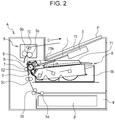
- FIG. 2 an overall configuration of the image forming apparatus will be described.
- Fig. 2 is a cross-sectional view of an apparatus main body A of the image forming apparatus and a cartridge B of the present example embodiment. Note that the apparatus main body A is a portion of the electrophotographic image forming apparatus in which the cartridge B has been excluded.
- the image forming apparatus illustrated in Fig. 2 is a laser beam printer employing an electrophotographic system and is a laser beam printer in which the cartridge B is detachable from the apparatus main body A.
- the apparatus main body A includes an exposing device 3 (a laser scanner unit) that forms a latent image on a photosensitive drum 62 serving as an image carrying member.
- a sheet tray 4 that contains sheets of paper (hereinafter, referred to as sheet materials P) serving as the recoding materials is disposed below the cartridge B.
- a pickup roller 5a, a pair of feed rollers 5b, a pair of conveyance rollers 5c, a transfer guide 6, a transfer roller 7, a conveyance guide 8, a fixing device 9, a pair of discharge rollers 10, a discharge tray 11, and other members are disposed in a conveying direction D of the sheet material P in the apparatus main body A.
- the fixing device 9 includes a heat roller 9a and a pressure roller 9b.
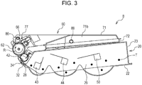
- Fig. 3 is a cross-sectional view of the cartridge B.
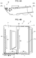
- Fig. 4A is a side view of the cartridge and Fig. 4B is a cross-sectional view of a photoreceptor unit.
- Fig. 4A is a side view of the cartridge B view in an axial direction of the photosensitive drum 62.
- Fig. 4B is a cross-sectional view of a photoreceptor unit 60 taken along line IVB-IVB in Fig. 4A .
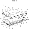
- Figs. 10 and 12 are perspective views illustrating a configuration of the cartridge B.
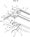
- Figs. 11 and 13 are partially enlarged views of the portions inside the broken lines in Figs. 10 and 12 viewed from angles different from those in Figs. 10 and 12 .
- the cartridge B includes the photoreceptor unit 60 and a developing unit 20.
- the photoreceptor unit 60 includes the photosensitive drum 62 serving as the image carrying member that carries an electrostatic latent image on a surface thereof.
- the photosensitive drum 62 includes a drive-side drum flange 63 on the drive side and a non-drive-side drum flange 64 on the non-drive side.
- the photoreceptor unit 60 includes a charge roller 66 serving as a charge member and a cleaning member 77 serving as a cleaning member that cleans a surface of the photosensitive drum 62.
- the photoreceptor unit 60 includes a drum frame 71 that supports the photosensitive drum 62, the charge roller 66, and the cleaning member 77.
- the charge roller 66 and the cleaning member 77 are each disposed in contact with an outer peripheral surface of the photosensitive drum 62.
- toner that has been removed from the surface of the photosensitive drum 62 with the cleaning member 77 is conveyed in a W1 direction with a first screw 86 serving as a removed toner conveying member and is passed on to a second screw 87.
- the toner that has been passed on to the second screw 87 is conveyed in a W2 direction.
- Some of the toner conveyed in the W2 direction is passed on to a third screw 88 and is conveyed in a W3 direction.
- the remaining toner is conveyed in a W4 direction with the second screw 87.
- the removed toner is accumulated in a removed toner chamber 71b formed in the drum frame 71.
- the developing unit 20 includes a development roller 32 serving as the developer carrying member that develops an electrostatic latent image, and a development blade 42 serving as a layer thickness regulating member that regulates a thickness of a toner layer on the development roller 32.
- the developing unit 20 includes a developer container 23 that supports the development roller 32 and the development blade 42 and that contains toner therein.
- a magnet roller 34 is provided inside the development roller 32.
- Space holding members (not shown) are attached to both ends of the development roller 32. The development roller 32 and the photosensitive drum 32 are held with a gap therebetween by having the space holding members abut against the photosensitive drum 62.
- a first conveying member 43, a second conveying member 44, and a third conveying member 50 are provided in the toner chamber 29 formed by the developer container 23 and the developing-unit bottom member 22.
- the first conveying member 43, the second conveying member 44, and the third conveying member 50 not only stir the toner accommodated inside the toner chamber 29 but also convey the toner to the toner supply chamber 28 in which the development roller 32 is provided.
- the photoreceptor unit 60 is provided with the drum frame 71, a lid member 72, the photosensitive drum 62, and a drum bearing 73 and a drum shaft 78 that rotatably support the photosensitive drum 62.
- the drive-side drum flange 63 is rotatably supported by a drum-unit sliding portion 73a of the drum bearing 73.
- the drum shaft 78 is press-fitted into a drum shaft support hole 71c provided in the drum frame 71, and the drum shaft 78 is inserted in the non-drive-side drum flange 64.
- the non-drive-side drum flange 64 is rotatably supported by the drum shaft 78.
- the development roller 32 is rotatably attached to the developer container 23 through the bearing members 27 and 37 provided at both ends of the development roller 32.
- a shaft 32a of the development roller 32 slides against a development roller sliding portion 27c provided in the bearing member 27.
- the bearing member 37 also includes a slide surface (not shown) that supports the shaft 32a.
- a drive side lateral member (hereinafter, referred to as a side cover) 26 is provided on the outer side of the bearing member 27 in the longitudinal direction. The side cover 26 is joined to the developer container 23 by ultrasonic spot welding. Details will be described later.
- the cartridge B is formed by pivotably connecting the photoreceptor unit 60 and the developing unit 20 to each other with connecting pins 69.
- first support hole 23a and a second support hole 23b are provided in the developer container 23.
- first suspension holes 71i and second suspension holes 71j are provided in the drum frame 71.
- a first hole portion 46Ra of a drive-side urging member 46R is hooked on a boss 73c of the drum bearing 73, and a second hole portion 46Rb is hooked on a boss 26a of the side cover 26.
- first hole portion 46Fa of a non-drive-side urging member 46F is hooked on a boss 71k of the drum frame 71, and a second hole portion 46Fb is hooked on a boss 37a of the bearing member 37.
- the drive-side urging member 46R and the non-drive-side urging member 46F are tension springs.
- the developing unit 20 By urging the developing unit 20 against the photoreceptor unit 60 with the urging force of the springs, the development roller 32 is biased towards the photosensitive drum 62. Furthermore, the developing roller 32 is held so as to form a predetermined space with the photosensitive drum 62 with space holding members 38 attached to the two end portions of the developing roller 32.
- the photosensitive drum 62 is rotationally driven in an arrow R direction at a predetermined speed ( Fig. 2 ).
- the charge member (the charge roller) 66 to which a voltage has been applied comes in contact with the outer peripheral surface of the photosensitive drum 62 and charges the outer peripheral surface of the photosensitive drum 62.
- the exposure device 3 outputs a laser beam L according to image information.
- the laser beam L passes through a laser opening 71H provided in the drum frame 71 of the cartridge B and exposes the outer peripheral surface of the photosensitive drum 62.
- an electrostatic latent image according to the image information is formed on the outer peripheral surface of the photosensitive drum 62.
- toner T inside the toner chamber 29 is conveyed by rotation of the first conveying member 43, the second conveying member 44, and the third conveying member 50, and is sent out to the toner supply chamber 28.
- the toner T is carried on a surface of the developing roller 32 with magnetic force of the magnet roller 34 (a stationary magnet). While the toner T is triboelectrically charged, the thickness of the toner T on the peripheral surface of the developing roller 32 is restricted with the developing blade 42.
- the toner carried on the surface of the development roller 32 is conveyed by the rotation of the development roller 32.
- a predetermined development voltage is applied to the development roller 32. With the potential difference between the photosensitive drum 62 and the development roller 32, the toner T is developed on the photosensitive drum 62 according to the electrostatic latent image. The electrostatic latent image is visualized as a toner image. The toner carried on the photosensitive drum 62 is conveyed by the rotation of the photosensitive drum 62.
- a first drive shaft 14 and a second drive shaft 19 that transmit the drive to the a first coupling 70 and a second coupling 21 provided in the cartridge B are provided in the apparatus main body A ( Fig. 8 ).
- the first drive shaft 14 and the second drive shaft 19 are driven with a motor (not shown) of the apparatus main body A.
- the photosensitive drum 62 connected to the first coupling 70 is rotated by receiving driving force from the apparatus main body A.
- the development roller 32 is rotated by having drive transmitted from the second coupling 21.
- power is supplied to the charge roller 66 and the development roller 32 from a power supply unit (not shown) of the main body A of the apparatus.
- the sheet material P contained in the sheet tray 4 below the apparatus main body A is sent out with the pickup roller 5a, the pair of feed rollers 5b, the pair of conveyance rollers 5c. Subsequently, the sheet material P passing through the transfer guide 6 is conveyed to a transfer position between the photosensitive drum 62 and the transfer roller 7. The toner image is transferred from the photosensitive drum 62 to the sheet member P at the transfer position.
- the sheet material P to which the toner image has been transferred is separated from the photosensitive drum 62 and is conveyed along the conveyance guide 8 to the fixing device 9. Subsequently, the sheet material P passes through a nip portion between the heat roller 9a and the pressure roller 9b included in the fixing device 9, and the toner image is fixed to the sheet material P.
- the sheet material P is conveyed to the pair of discharge rollers 10 and is discharged on a discharge tray 11.
- the residual toner on the outer peripheral surface of the photosensitive drum 62 after the transferring is removed by the cleaning member 77 and the photosensitive drum 62 is used once more in the image forming process.
- the toner removed from the photosensitive drum 62 is stored in the removed toner chamber 71b of the photoreceptor unit 60.
- the charge roller 66, the developing roller 32, the transfer roller 7, the cleaning member 77 that have been described above are process members that act on the photosensitive drum 62.
- Fig. 5 is a perspective view of the apparatus main body A in which an openable/closable door 13 is open for attaching and detaching the cartridge B.
- Fig. 6 is a perspective view of the apparatus main body A and the cartridge B in a state in which the openable/closable door 13 is open and a tray 18 has been drawn out to attach/detach the cartridge B.
- Fig. 7 is a perspective view of the apparatus main body A and the cartridge B in a state in which the openable/closable door 13 is open and the tray 18 has been drawn out and while the cartridge B is being attached/detached.
- the cartridge B is detachably attachable in an attaching and detaching direction E with respect to the tray 18.
- the openable/closable door 13 is attached to the main body A of the apparatus in a pivotal manner. When the openable/closable door 13 is opened, a cartridge insertion port 17 becomes exposed.
- the tray 18 for mounting the cartridge B in the apparatus main body is provided in the cartridge insertion port 17.
- the cartridge B can be attached/detached when the tray 18 is drawn out to a predetermined position. In a state in which the cartridge B is mounted on the tray 18, the cartridge B is mounted in the apparatus main body A in an arrow C direction in the drawing along guide rails (not shown).
- Fig. 8 is a diagram illustrating a support mechanism of the cartridge on the drive side.
- Fig. 9 is a diagram illustrating a support mechanism of the cartridge on the non-drive side.
- the apparatus main body A is provided with a drive side plate 15 and a non-drive side plate 16 that support the cartridge B.
- the drive side plate 15 is provided with a first supporting portion 15a, a second supporting portion 15b, and a rotation regulating portion 15c that regulates the rotation of the cartridge B.
- the non-drive side plate 16 is provided with a first supporting portion 16a, a second supporting portion 16b, and a rotation regulating portion 16c that regulates the rotation of the cartridge B.
- a supported portion 73b and a supported portion 73d are provided in the drum bearing 73 of the cartridge B.
- a regulated portion 71a is provided on the drive side of the drum frame 71 and a supported portion 71f and a regulated portion 71g are provided on the non-drive side.
- the supported portion 73b abuts against the first supporting portion 15a.
- the supported portion 73d abuts against the second supporting portion 15b.
- the regulated portion 71a abuts against the rotation regulating portion 15c.
- the supported portion 71f abuts against the first supporting portion 16a and the second supporting portion 16b.
- the regulated portion 71g abuts against the rotation regulating portion 16c.
- Ultrasonic spot welding is one of the methods of joining two members using an ultrasonic wave.
- an oscillator that generates an ultrasonic vibration
- a resonance member that is attached to the oscillator and that transmits the ultrasonic vibration to other members
- the resonance member is referred to as a horn or a welding horn.
- a certain amount of pressure is applied to the members with the welding horn to apply ultrasonic vibration thereto.
- frictional heat is generated in resin of the two members. The above frictional heat melts the resin of the two members and joins the resin of the two members to each other.
- the materials of the members joined to each other by ultrasonic welding desirably include thermoplastic resin. Furthermore, in order to increase the joining strength between the two members, the materials of the two members, at least at the melted portions, are compatible to each other. More desirably, the materials of the two members are the same.
- styrenic thermoplastic resin having the same material quality is used as the material of the developer container 23 serving as a first member and the material of the side cover 26 serving as a second member that are described later.
- a welding horn H includes a cylindrical portion Hc having a diameter D1, and a tapered portion Hb in which a diameter thereof becomes smaller from the cylindrical portion towards a horn tip portion Ha.
- the horn tip portion Ha has a pointed shape.
- the side cover 26 serving as the second member is joined to the developer container 23 serving as the first member by ultrasonic spot welding.
- Figs. 14 to 16 are perspective views illustrating a positioning process of the side cover 26 and the developer container 23.
- Fig. 17 is a perspective view illustrating a process of joining the side cover 26 and the developer container 23 to each other by ultrasonic spot welding.
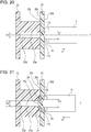
- Figs. 1 and 18 to 22 are cross-sectional views illustrating the process of joining the side cover 26 and the developer container 23 by ultrasonic spot welding.
- Figs. 1 and 18 to 22 are drawings of cross sections each taken along a line that are orthogonal to a first contact surface 23c described later and a normal line that passes the center of a retaining hole portion 23d and are drawings each viewed in a direction orthogonal to the cross section.
- a manufacturing method of the cartridge B includes a holding step in which the side cover 26 and the developer container 23 are held at positions at which ultrasonic spot welding are performed.
- the holding step will be described.
- the developer container 23 includes first contact surfaces 23c serving as receiving surfaces. Furthermore, the first contact surfaces 23c are provided with retaining hole portions 23d serving as retaining portions. In other words, the retaining portions are recesses that are each recessed in a direction intersecting (in an orthogonal direction in the present example embodiment) the corresponding first contact surface 23c and are holes that each have a diameter D2 in the present example embodiment.
- the first contact surfaces 23c are oriented in the longitudinal direction.
- the first contact surfaces 23c are surfaces that intersect (orthogonal to, in the present example embodiment) the longitudinal direction.
- the first contact surfaces 23c in which the retaining hole portions 23d are provided are provided at a plurality of positions in the developer container 23.
- the number of first contact surfaces 23c provided with the retaining hole portions 23d is two.
- the number of first contact surfaces 23c provided with the retaining hole portions 23d may be one.
- a reference hole 27a and a long hole 27b described later are provided in the bearing member 27 fixed to the developer container 23.
- the side cover 26 includes a second contact surface 26c serving as a contact surface in contact with the first contact surfaces 23c.
- the second contact surface 26c configured so as to be situated along and in contact with the first contact surfaces 23c.
- a reference hole 26b and a long hole 26e described later are provided in the side cover 26.
- the side cover 26 and a holding member 90 used in installing the side cover 26 are disposed on one end side of the developer container 23 in the longitudinal direction. Furthermore, a backup member 91 is disposed on the other end side of the developer container 23 in the longitudinal direction.
- the holding member 90 includes shafts 90a and 90b fitted in the reference hole 26b and the long hole 26e of the side cover 26.
- the developer container 23 and the side cover 26 are moved to positions at which the first contact surfaces 23c and the second contact surface 26c of the side cover 26 abut against each other.
- the developer container 23 and the side cover 26 are held at positions (holding positions) at which the ultrasonic spot welding is performed.
- the first contact surfaces 23c and the second contact surface 26c are in contact with each other.
- the retaining hole portions 23d are covered by the second contact surface 26c.
- the first contact surfaces 23c and the second contact surface 26c are flat surfaces formed parallel to each other at the holding positions.
- the first contact surfaces 23c and the second contact surface 26c are, desirably, flat surfaces that abut against each other at least at the circumferences (rim portions) of the retaining hole portions 23d.
- the first contact surfaces 23c and the second contact surface 26c do not have to be perfectly flat surfaces or perfectly parallel to each other.
- at least either of the first contact surfaces 23c and the second contact surface 26c may be deformed by the holding member 90 so that the first contact surfaces 23c and the second contact surface 26c abut against each other.
- the position of the side cover 26 with respect to the bearing member 27 and the developer container 23 is set in the above manner and the side cover 26 is held at the position in which ultrasonic spot welding is performed.
- the manufacturing method of the cartridge B includes a joining step in which the side cover 26 and the developer container 23 held at the holding positions in the holding step described above are joined to each other by ultrasonic spot welding.
- the joining step will be described.
- the welding horn H is disposed outside of the side cover 26.
- the welding horn H moves in an arrow H1 direction (a horn entering direction HI) in Fig. 18 .
- the welding horn H moves in a direction intersecting the first contact surfaces 23c (desirably, a direction normal to the first contact surfaces 23c).
- the horn tip portion Ha of the welding horn H abuts against an opposing surface 26d of the side cover 26.
- the opposing surface 26d is a surface that is on the opposite side (on the back surface side) of the second contact surface 26c and is a surface that is parallel to the second contact surface 26c.
- the welding horn H moves from the side cover 26 side towards the developer container 23 side so that the side cover 26 is melted towards the retaining hole portions 23d of the first contact surfaces 23c.
- Figs. 1 , 18 , 19 , 20 , 21 , and 22 are cross-sectional views of the welded position X taken along lines I-I, XVIII-XVIII, XVIIII-XVIIII, XX-XX, XI-XI, and XXII-XXII, respectively, (see Fig. 17 ), and are cross-sectional views illustrating only the portions related to the joining performed by ultrasonic spot welding.
- a method of joining the side cover 26 to the developer container 23 by ultrasonic spot welding will be described step-by-step with reference to Figs. 1 and 18 to 22 .
- the welding horn H includes a cylindrical portion Hc having a diameter D1, and the tapered portion Hb in which the diameter thereof becomes smaller from the cylindrical portion towards the horn tip portion Ha. Furthermore, the second contact surface 26c abuts against the first contact surface 23c. Note that the center axis Z of the cylindrical portion Hc passes through the horn tip portion Ha. Moreover, the direction of the center axis Z is the same as the horn entering direction H1.
- the direction of the center axis Z is parallel to a line normal to the first contact surface 23c. Furthermore, the direction of the center axis Z is parallel to a line normal to the second contact surface 26c. Furthermore, the center axis Z passes the center of the retaining hole portion 23d. In other words, the center axis Z is orthogonal to the first contact surface 23c or the second contact surface 26c and coincides with a normal line passing through the center of the retaining hole portion 23d.
- the horn tip portion Ha When viewed in the direction normal to the first contact surface 23c, the horn tip portion Ha is disposed so as to overlap the retaining hole portion 23d. In other words, in a direction normal to the first contact surface 23c (same as the direction normal to the second contact surface 26c), the position of the retaining hole portion 23d and the position of the horn tip portion Ha overlap each other. In other words, the horn tip portion Ha abuts against the opposing surface 26d in an area formed when the retaining hole portion 23d is projected on the opposing surface 26d in the direction normal to the first contact surface 23c. In other words, the horn tip portion Ha is disposed so that the line orthogonal to the first contact surface 23c and that passes through the horn tip portion Ha passes through the retaining hole portion 23d.
- the welding horn H By moving the welding horn H in the horn entering direction H1, as illustrated in Fig. 19 , the horn tip portion Ha abuts against the opposing surface 26d in the area where the retaining hole portion 23d having the diameter D2 is projected on the opposing surface 26d. In so doing, the welding horn H applies a predetermined load on the opposing surface 26d in the horn entering direction H1. By vibrating while applying the predetermined load on the opposing surface 26d, the welding horn H generates frictional heat between the horn tip portion Ha and the opposing surface 26d. A portion of the opposing surface 26d is melted by the frictional heat and, as illustrated in Fig. 20 , the welding horn H enters into the side cover 26.
- the welding horn H By having the welding horn H enter into the side cover 26 and apply ultrasonic vibration thereto, as illustrated in Fig. 21 , the welding horn H further enters into the side cover 26.
- a protrusion 26e is formed on the second contact surface 26c.
- the protrusion 26e is protruded into the retaining hole portion 23d.
- the ultrasonic vibration applied by the welding horn H is transmitted to the second contact surface 26c through the side cover 26.
- frictional heat is generated between the second contact surface 26c and the first contact surface 23c and the second contact surface 26c and the first contact surface 23c become melted; accordingly, a fused portion is formed.
- the fused portion formed in the circumference of the retaining hole portion 23d is referred to as a first fused portion 24.
- a portion of the fused portion flows in an arrow J direction in Fig. 22 along a lateral surface portion 23e of the retaining hole portion 23d and makes its way into the retaining hole portion 23d.
- the above portion is referred to as a second fused portion 25.
- the second fused portion 25 is in contact with the lateral surface portion 23e of the retaining hole portion 23d. While the first fused portion 24 and the second fused portion 25 are connected and integral, the first fused portion 24 and the second fused portion 25 are depicted separately in Fig. 22 and other drawings.
- the welding horn H is retracted in an arrow H2 direction, and the first fused portion 24 and the second fused portion 25 become cooled and solidified.
- the side cover 26 and the developer container 23 become integrally joined to each other.
- the holding member 90 and the backup member 91 are moved at a timing different to that of the welding horn H; however, the above can be performed at the same time. In such a case, it is only sufficient that the first contact surface 23c and the second contact surface 26c are abutted against each other before the welding horn H abuts against the side cover 26.
- the second contact surface 26c covers the retaining hole portion 23d of the first contact surface 23c. Furthermore, the first contact surface 23c and the second contact surface 26c are in contact with each other. A recess 26f recessed towards the retaining hole portion 23d is formed in the side cover 26. Furthermore, at least a portion (the second fused portion 25) of the fused portion is situated inside the retaining hole portion 23d. In other words, the amount of fused portion entering between the second contact surface 26c and the first contact surface 23c that determine the longitudinal position of the side cover 26 and the developer container 23 can be reduced, and separation of the first contact surfaces 23c and the second contact surface 26c can be reduced.
- the side cover 26 and the developer container 23 are joined not only at the first fused portion 24 but also at the second fused portion 25, the joining area is increased and the joining strength can be increased.
- the first fused portion 24 and the second fused portion 25 are formed in a H3 direction, which is a direction in which the side cover 26 and the developer container 23 are separated, and a direction that intersects the H3 direction. Accordingly, separation strength of the side cover 26 with respect to the developer container 23 can be improved.
- Fig. 23 is a diagram of the recess 26f viewed in the direction normal to the first contact surface 23c.
- Fig. 23 is a diagram viewed from the side cover 26 side and in the direction normal to the first contact surface 23c.
- the recess 26f has a shape in which the shape of the welding horn H has been transferred.
- the recess 26f includes an inclination portion 26g formed by the tapered portion Hb.
- a recess tip portion 26h formed by the horn tip portion Ha is formed in the recess 26f.
- a cylindrical portion 26i formed by the cylindrical portion Hc is formed in the recess 26f.
- the inclination portion 26g extends in a direction intersecting the normal line of the first contact surface 23c.
- An end portion of the inclination portion 26g positioned on the center side of the recess is referred to as a first end portion 26g1, and an end portion on the other side is referred to as a second end portion 26g2.
- the first end portion 26g1 is connected to the recess tip portion 26h.
- the second end portion 26g2 is connected to the cylindrical portion 26i. As illustrated in Fig. 23 , when viewed in the direction normal to the first contact surface 23c, the first end portion 26g1 is positioned inside the retaining hole portion 23d. Furthermore, the second end portion 26g2 is positioned outside the retaining hole portion 23d.
- the recess 26f is provided so as to have a depth that does not reach the first contact surface 23c. In other words, the recess 26f is positioned on an opposite side of the retaining hole portion 23d with respect to the first contact surface 23c.
- the side cover 26 and the bearing member 27 are configured as separate members; however, the side cover 26 and the bearing member 27 can be formed integrally.
- the present disclosure is not limited to the above and can be used to join other components to each other.
- the present disclosure can be used to join the drum bearing 73 and the drum frame 71 provided in the photoreceptor unit 60 to each other.
- the present disclosure can be used to join the bearing member 27 and the developer container 23 to each other.
- the cartridge of the present disclosure is detachably attachable to the apparatus main body
- the cartridge may be one that is fixed to the apparatus main body.
- the cartridge B includes rotary members such as the photosensitive drum 62 and the development roller 32.
- the cartridge B further includes sliding portions such as the drum-unit sliding portion 73a and the development roller sliding portion 27c that abut against and rotatably support the rotary members.
- the fused portions are formed at positions that are distanced away from the sliding portions. By so doing, the rotations of the rotary members can be prevented from becoming unstable due to the melting of the sliding portions.
- the rotary members other than the photosensitive drum 62 and the development roller 32 can be rotated in a stable manner.
- the cartridge B is provided with positioning portions (the supported portion 73b, the supported portion 73d, the regulated portion 71a, the supported portion 7 1 f, and the regulated portion 71g) that set the position of the cartridge B with respect to the apparatus main body.
- the fused portions are set at positions that are distanced away from the positioning portions.
- the versatility of the device is high and components such as screws can be omitted. Accordingly, the cost of the components and the cost of the assembly device can be reduced. Furthermore, compared with a case using an adhesive agent, the time needed for the joining is short.
- the present disclosure is capable of reducing the amount of fused portion of the members entering into a portion between one member and the other member when a plurality of members are joined by ultrasonic spot welding.
Landscapes
- Engineering & Computer Science (AREA)
- Physics & Mathematics (AREA)
- General Physics & Mathematics (AREA)
- Life Sciences & Earth Sciences (AREA)
- Sustainable Development (AREA)
- Computer Vision & Pattern Recognition (AREA)
- Manufacturing & Machinery (AREA)
- Mechanical Engineering (AREA)
- Electrophotography Configuration And Component (AREA)
Abstract
Description
- The present disclosure relates to a cartridge being attachable to an apparatus main body of an image forming apparatus using an electrophotographic system and to a manufacturing method of the cartridge.
- A cartridge includes developer, an electrophotographic photosensitive member, and components such as a processing member that acts on the electrophotographic photosensitive member. The cartridge is attached to an apparatus main body of an image forming apparatus.
- The image forming apparatus includes an electrophotographic copying machine, an electrophotographic printer (LED printer, laser printer, and the like), a facsimile machine, and a word processor.
- In a case in which a cartridge attached to an image forming apparatus includes a plurality of members, a fastening member such as a screw may be used as a joining member that joins the plurality of members to each other.
- As a method of joining the plurality of members included in the cartridge, a so-called ultrasonic welding that joins the members to each other with ultrasonic vibration is known. In ultrasonic welding, an ultrasonic vibrator that includes a resonance member that transmits ultrasonic vibration to a member by abutting against the member is used. As a method of ultrasonic welding, ultrasonic spot welding is known that uses a resonance member having a tip with a pointed shape.
- In ultrasonic spot welding, the tip of the resonance member is abutted against one member and is moved towards the other member. In so doing, a fused portion in which the one member and the other member are melted is formed. Moreover, a recess recessed towards the other member is formed in the one member that has been melted by the resonance member abutting thereagainst.
- Disclosed in Japanese Patent Laid-Open No.
2005-49762 - In a case in which a plurality of members are joined to each other by ultrasonic spot welding, when a large amount of fused portion enters between one member and the other member, the members may become separated from each other.
- The present disclosure provides a cartridge in which the amount of fused portion of the members entering a portion between one member and the other member when a plurality of members are joined by ultrasonic spot welding is reduced.
- The present disclosure in its first aspect provides a manufacturing method of a cartridge as specified in claims 1 to 8.
- The present disclosure in its second aspect provides a cartridge as specified in
claims 9 to 15. - Further features of the present invention will become apparent from the following description of embodiments with reference to the attached drawings.
-
-
Fig. 1 is a cross-sectional view illustrating joining by ultrasonic spot welding according to a first example embodiment. -
Fig. 2 is a cross-sectional view of an apparatus main body of an image forming apparatus and a cartridge according to the first example embodiment. -
Fig. 3 is a cross-sectional view of the cartridge according to the first embodiment. -
Fig. 4A is a side view of the cartridge andFig. 4B is a cross-sectional view of a photoreceptor unit. -
Fig. 5 is a perspective view of an image forming apparatus main body in which an openable/closable door of an electrophotographic image forming apparatus is open. -
Fig. 6 is a perspective view of the apparatus main body according to the first example embodiment in a state in which the openable/closable door is open and a tray has been drawn out. -
Fig. 7 is a perspective view of the apparatus main body and the cartridge according to the first example embodiment when the cartridge is attached/detached from the tray while in a state in which the openable/closable door is open and the tray has been drawn out. -
Fig. 8 is a perspective view illustrating a support of the cartridge according to the first example embodiment. -
Fig. 9 is a perspective view illustrating a support of the cartridge according to the first example embodiment. -
Fig. 10 is a perspective view illustrating a configuration of the cartridge according to the first example embodiment. -
Fig. 11 is an enlarged view illustrating the configuration of the cartridge according to the first example embodiment. -
Fig. 12 is a perspective view illustrating the configuration of the cartridge according to the first example embodiment. -
Fig. 13 is an enlarged view illustrating the configuration of the cartridge according to the first example embodiment. -
Fig. 14 is a perspective view illustrating a developing unit according to the first example embodiment. -
Fig. 15 is a perspective view illustrating a developing unit according to the first example embodiment. -
Fig. 16 is a perspective view illustrating a developing unit according to the first example embodiment. -
Fig. 17 is a perspective view illustrating joining by ultrasonic spot welding according to the first example embodiment. -
Fig. 18 is a cross-sectional view illustrating joining by ultrasonic spot welding according to the first example embodiment. -
Fig. 19 is a cross-sectional view illustrating joining by ultrasonic spot welding according to the first example embodiment. -
Fig. 20 is a cross-sectional view illustrating joining by ultrasonic spot welding according to the first example embodiment. -
Fig. 21 is a cross-sectional view illustrating joining by ultrasonic spot welding according to the first example embodiment. -
Fig. 22 is a cross-sectional view illustrating joining by ultrasonic spot welding according to the first example embodiment. -
Fig. 23 is a plan view illustrating joining by ultrasonic spot welding according to the first example embodiment. - Hereinafter, an example embodiment of the present disclosure will be exemplified with reference to the drawings. Note that in principle, the dimensions, the materials, and the shapes of the components, the relative configuration of the components, and the like that are described in the following example embodiment are to be appropriately altered based on the configuration of the device to which the present disclosure is applied and on various conditions, and the scope of the present disclosure is not intended to be limited by the following example embodiment.
- Furthermore, a rotational axis of an image carrying member described later and a rotational axis of a developer carrying member that are described later in the present example embodiment are practically parallel to each other. Moreover, a longitudinal direction is practically the same as the direction in which the rotational axis of the image carrying member and the direction in which the rotational axis of the developer carrying member extend.
- Hereinafter, the example embodiment of the present disclosure will be described in detail with reference to the drawings. In the longitudinal direction, a side on which a photosensitive drum receives driving force from an image forming apparatus main body (apparatus main body) is referred to as a drive side, and a side opposite to the drive side is referred to as a non-drive side.
- Referring to
Fig. 2 , an overall configuration of the image forming apparatus will be described. -
Fig. 2 is a cross-sectional view of an apparatus main body A of the image forming apparatus and a cartridge B of the present example embodiment. Note that the apparatus main body A is a portion of the electrophotographic image forming apparatus in which the cartridge B has been excluded. - The image forming apparatus illustrated in
Fig. 2 is a laser beam printer employing an electrophotographic system and is a laser beam printer in which the cartridge B is detachable from the apparatus main body A. The apparatus main body A includes an exposing device 3 (a laser scanner unit) that forms a latent image on aphotosensitive drum 62 serving as an image carrying member. Furthermore, a sheet tray 4 that contains sheets of paper (hereinafter, referred to as sheet materials P) serving as the recoding materials is disposed below the cartridge B. - Furthermore, a
pickup roller 5a, a pair offeed rollers 5b, a pair ofconveyance rollers 5c, a transfer guide 6, atransfer roller 7, aconveyance guide 8, afixing device 9, a pair ofdischarge rollers 10, adischarge tray 11, and other members are disposed in a conveying direction D of the sheet material P in the apparatus main body A. Thefixing device 9 includes aheat roller 9a and apressure roller 9b. - An overall configuration of the cartridge B will be described with reference to
Figs. 2 to 4B , and10 to 13 . -
Fig. 3 is a cross-sectional view of the cartridge B.Fig. 4A is a side view of the cartridge andFig. 4B is a cross-sectional view of a photoreceptor unit.Fig. 4A is a side view of the cartridge B view in an axial direction of thephotosensitive drum 62.Fig. 4B is a cross-sectional view of aphotoreceptor unit 60 taken along line IVB-IVB inFig. 4A .Figs. 10 and12 are perspective views illustrating a configuration of the cartridge B.Figs. 11 and13 are partially enlarged views of the portions inside the broken lines inFigs. 10 and12 viewed from angles different from those inFigs. 10 and12 . - In the present example embodiment, the cartridge B includes the
photoreceptor unit 60 and a developingunit 20. - As illustrated in
Fig. 3 , thephotoreceptor unit 60 includes thephotosensitive drum 62 serving as the image carrying member that carries an electrostatic latent image on a surface thereof. As illustrated inFigs. 11 and13 , thephotosensitive drum 62 includes a drive-side drum flange 63 on the drive side and a non-drive-side drum flange 64 on the non-drive side. As illustratedFig. 3 , thephotoreceptor unit 60 includes acharge roller 66 serving as a charge member and a cleaningmember 77 serving as a cleaning member that cleans a surface of thephotosensitive drum 62. Thephotoreceptor unit 60 includes adrum frame 71 that supports thephotosensitive drum 62, thecharge roller 66, and the cleaningmember 77. Thecharge roller 66 and the cleaningmember 77 are each disposed in contact with an outer peripheral surface of thephotosensitive drum 62. - As illustrated in
Figs. 3 ,4A, and 4B , toner that has been removed from the surface of thephotosensitive drum 62 with the cleaningmember 77 is conveyed in a W1 direction with afirst screw 86 serving as a removed toner conveying member and is passed on to asecond screw 87. The toner that has been passed on to thesecond screw 87 is conveyed in a W2 direction. Some of the toner conveyed in the W2 direction is passed on to athird screw 88 and is conveyed in a W3 direction. The remaining toner is conveyed in a W4 direction with thesecond screw 87. Then, the removed toner is accumulated in a removedtoner chamber 71b formed in thedrum frame 71. - As illustrated in
Fig. 3 , the developingunit 20 includes adevelopment roller 32 serving as the developer carrying member that develops an electrostatic latent image, and adevelopment blade 42 serving as a layer thickness regulating member that regulates a thickness of a toner layer on thedevelopment roller 32. Moreover, the developingunit 20 includes adeveloper container 23 that supports thedevelopment roller 32 and thedevelopment blade 42 and that contains toner therein. Amagnet roller 34 is provided inside thedevelopment roller 32. Space holding members (not shown) are attached to both ends of thedevelopment roller 32. Thedevelopment roller 32 and thephotosensitive drum 32 are held with a gap therebetween by having the space holding members abut against thephotosensitive drum 62. - A first conveying
member 43, a second conveyingmember 44, and a third conveying member 50 are provided in thetoner chamber 29 formed by thedeveloper container 23 and the developing-unit bottom member 22. The first conveyingmember 43, the second conveyingmember 44, and the third conveying member 50 not only stir the toner accommodated inside thetoner chamber 29 but also convey the toner to thetoner supply chamber 28 in which thedevelopment roller 32 is provided. - As illustrated in
Figs. 3 ,11 , and13 , thephotoreceptor unit 60 is provided with thedrum frame 71, alid member 72, thephotosensitive drum 62, and adrum bearing 73 and adrum shaft 78 that rotatably support thephotosensitive drum 62. As illustrated inFig. 13 , the drive-side drum flange 63 is rotatably supported by a drum-unit sliding portion 73a of thedrum bearing 73. Meanwhile, as illustrated inFig. 11 , thedrum shaft 78 is press-fitted into a drumshaft support hole 71c provided in thedrum frame 71, and thedrum shaft 78 is inserted in the non-drive-side drum flange 64. The non-drive-side drum flange 64 is rotatably supported by thedrum shaft 78. - As illustrated in
Figs. 3 ,10 ,12 , and13 , thedevelopment roller 32 is rotatably attached to thedeveloper container 23 through the bearingmembers development roller 32. As illustrated inFig. 13 , ashaft 32a of thedevelopment roller 32 slides against a developmentroller sliding portion 27c provided in the bearingmember 27. The bearingmember 37 also includes a slide surface (not shown) that supports theshaft 32a. Moreover, a drive side lateral member (hereinafter, referred to as a side cover) 26 is provided on the outer side of the bearingmember 27 in the longitudinal direction. The side cover 26 is joined to thedeveloper container 23 by ultrasonic spot welding. Details will be described later. - As illustrated in
Figs. 11 and13 , the cartridge B is formed by pivotably connecting thephotoreceptor unit 60 and the developingunit 20 to each other with connectingpins 69. - Specifically, at the end portions of the developing
unit 20 in the longitudinal direction, afirst support hole 23a and asecond support hole 23b are provided in thedeveloper container 23. Furthermore, at each end portion of thephotoreceptor unit 60 in the longitudinal direction,first suspension holes 71i andsecond suspension holes 71j are provided in thedrum frame 71. By having the connectingpins 69 press-fitted and fixed in thefirst suspension holes 71i and thesecond suspension holes 71j fit into thefirst support hole 23a and thesecond support hole 23b, thephotoreceptor unit 60 and the developingunit 20 are pivotably connected to each other. - Furthermore, a first hole portion 46Ra of a drive-
side urging member 46R is hooked on aboss 73c of the drum bearing 73, and a second hole portion 46Rb is hooked on aboss 26a of theside cover 26. - Furthermore a first hole portion 46Fa of a non-drive-
side urging member 46F is hooked on aboss 71k of thedrum frame 71, and a second hole portion 46Fb is hooked on aboss 37a of the bearingmember 37. - In the present example embodiment, the drive-
side urging member 46R and the non-drive-side urging member 46F are tension springs. By urging the developingunit 20 against thephotoreceptor unit 60 with the urging force of the springs, thedevelopment roller 32 is biased towards thephotosensitive drum 62. Furthermore, the developingroller 32 is held so as to form a predetermined space with thephotosensitive drum 62 withspace holding members 38 attached to the two end portions of the developingroller 32. - Referring next to
Figs. 2 and3 , an outline of the image forming process will be described. - Based on a print start signal, the
photosensitive drum 62 is rotationally driven in an arrow R direction at a predetermined speed (Fig. 2 ). - The charge member (the charge roller) 66 to which a voltage has been applied comes in contact with the outer peripheral surface of the
photosensitive drum 62 and charges the outer peripheral surface of thephotosensitive drum 62. - The
exposure device 3 outputs a laser beam L according to image information. The laser beam L passes through a laser opening 71H provided in thedrum frame 71 of the cartridge B and exposes the outer peripheral surface of thephotosensitive drum 62. With the above, an electrostatic latent image according to the image information is formed on the outer peripheral surface of thephotosensitive drum 62. - Meanwhile, as illustrated in
Fig. 3 , in the developingunit 20 serving as a developing device, toner T inside thetoner chamber 29 is conveyed by rotation of the first conveyingmember 43, the second conveyingmember 44, and the third conveying member 50, and is sent out to thetoner supply chamber 28. The toner T is carried on a surface of the developingroller 32 with magnetic force of the magnet roller 34 (a stationary magnet). While the toner T is triboelectrically charged, the thickness of the toner T on the peripheral surface of the developingroller 32 is restricted with the developingblade 42. The toner carried on the surface of thedevelopment roller 32 is conveyed by the rotation of thedevelopment roller 32. - A predetermined development voltage is applied to the
development roller 32. With the potential difference between thephotosensitive drum 62 and thedevelopment roller 32, the toner T is developed on thephotosensitive drum 62 according to the electrostatic latent image. The electrostatic latent image is visualized as a toner image. The toner carried on thephotosensitive drum 62 is conveyed by the rotation of thephotosensitive drum 62. - Note that a
first drive shaft 14 and asecond drive shaft 19 that transmit the drive to the afirst coupling 70 and asecond coupling 21 provided in the cartridge B are provided in the apparatus main body A (Fig. 8 ). Thefirst drive shaft 14 and thesecond drive shaft 19 are driven with a motor (not shown) of the apparatus main body A. With the above, thephotosensitive drum 62 connected to thefirst coupling 70 is rotated by receiving driving force from the apparatus main body A. Furthermore, thedevelopment roller 32 is rotated by having drive transmitted from thesecond coupling 21. Moreover, power is supplied to thecharge roller 66 and thedevelopment roller 32 from a power supply unit (not shown) of the main body A of the apparatus. - Meanwhile, as illustrated in
Fig. 2 , the sheet material P contained in the sheet tray 4 below the apparatus main body A is sent out with thepickup roller 5a, the pair offeed rollers 5b, the pair ofconveyance rollers 5c. Subsequently, the sheet material P passing through the transfer guide 6 is conveyed to a transfer position between thephotosensitive drum 62 and thetransfer roller 7. The toner image is transferred from thephotosensitive drum 62 to the sheet member P at the transfer position. - The sheet material P to which the toner image has been transferred is separated from the
photosensitive drum 62 and is conveyed along theconveyance guide 8 to thefixing device 9. Subsequently, the sheet material P passes through a nip portion between theheat roller 9a and thepressure roller 9b included in thefixing device 9, and the toner image is fixed to the sheet material P. The sheet material P is conveyed to the pair ofdischarge rollers 10 and is discharged on adischarge tray 11. - Meanwhile, as illustrated in
Fig. 3 , the residual toner on the outer peripheral surface of thephotosensitive drum 62 after the transferring is removed by the cleaningmember 77 and thephotosensitive drum 62 is used once more in the image forming process. The toner removed from thephotosensitive drum 62 is stored in the removedtoner chamber 71b of thephotoreceptor unit 60. - The
charge roller 66, the developingroller 32, thetransfer roller 7, the cleaningmember 77 that have been described above are process members that act on thephotosensitive drum 62. - Referring next to
Figs. 5 ,6 , and7 , attachment and detachment of the cartridge B with respect to the apparatus main body A will be described. -
Fig. 5 is a perspective view of the apparatus main body A in which an openable/closable door 13 is open for attaching and detaching the cartridge B.Fig. 6 is a perspective view of the apparatus main body A and the cartridge B in a state in which the openable/closable door 13 is open and atray 18 has been drawn out to attach/detach the cartridge B.Fig. 7 is a perspective view of the apparatus main body A and the cartridge B in a state in which the openable/closable door 13 is open and thetray 18 has been drawn out and while the cartridge B is being attached/detached. The cartridge B is detachably attachable in an attaching and detaching direction E with respect to thetray 18. - The openable/
closable door 13 is attached to the main body A of the apparatus in a pivotal manner. When the openable/closable door 13 is opened, acartridge insertion port 17 becomes exposed. Thetray 18 for mounting the cartridge B in the apparatus main body is provided in thecartridge insertion port 17. The cartridge B can be attached/detached when thetray 18 is drawn out to a predetermined position. In a state in which the cartridge B is mounted on thetray 18, the cartridge B is mounted in the apparatus main body A in an arrow C direction in the drawing along guide rails (not shown). - Referring to
Figs. 5 ,8 , and9 , a support mechanism of the cartridge B will be described. -
Fig. 8 is a diagram illustrating a support mechanism of the cartridge on the drive side.Fig. 9 is a diagram illustrating a support mechanism of the cartridge on the non-drive side. - As illustrated in
Fig. 5 , the apparatus main body A is provided with adrive side plate 15 and anon-drive side plate 16 that support the cartridge B. As illustrated inFigs. 8 and9 , thedrive side plate 15 is provided with a first supportingportion 15a, a second supportingportion 15b, and arotation regulating portion 15c that regulates the rotation of the cartridge B. Thenon-drive side plate 16 is provided with a first supportingportion 16a, a second supportingportion 16b, and arotation regulating portion 16c that regulates the rotation of the cartridge B. - A supported
portion 73b and a supportedportion 73d are provided in the drum bearing 73 of the cartridge B. Aregulated portion 71a is provided on the drive side of thedrum frame 71 and a supportedportion 71f and aregulated portion 71g are provided on the non-drive side. - The supported
portion 73b abuts against the first supportingportion 15a. The supportedportion 73d abuts against the second supportingportion 15b. Theregulated portion 71a abuts against therotation regulating portion 15c. The supportedportion 71f abuts against the first supportingportion 16a and the second supportingportion 16b. Theregulated portion 71g abuts against therotation regulating portion 16c. With the above, the position of the cartridge B with respect to the apparatus main body A is set inside the apparatus main body A. - A method of joining by ultrasonic spot welding used in the present disclosure will be described. Ultrasonic spot welding is one of the methods of joining two members using an ultrasonic wave.
- In ultrasonic welding, an oscillator that generates an ultrasonic vibration, and a resonance member that is attached to the oscillator and that transmits the ultrasonic vibration to other members are used. The resonance member is referred to as a horn or a welding horn. A certain amount of pressure is applied to the members with the welding horn to apply ultrasonic vibration thereto. With the above, frictional heat is generated in resin of the two members. The above frictional heat melts the resin of the two members and joins the resin of the two members to each other.
- The materials of the members joined to each other by ultrasonic welding desirably include thermoplastic resin. Furthermore, in order to increase the joining strength between the two members, the materials of the two members, at least at the melted portions, are compatible to each other. More desirably, the materials of the two members are the same. In the present example embodiment, styrenic thermoplastic resin having the same material quality is used as the material of the
developer container 23 serving as a first member and the material of theside cover 26 serving as a second member that are described later. - The welding horn used in ultrasonic spot welding will be described. As illustrated in
Fig. 18 , a welding horn H includes a cylindrical portion Hc having a diameter D1, and a tapered portion Hb in which a diameter thereof becomes smaller from the cylindrical portion towards a horn tip portion Ha. In other words, in the welding horn, the horn tip portion Ha has a pointed shape. By using a welding horn having such a tip shape, the members can be joined to each other without the need of forming, in the joined member, a protruded shape (a so-called ultrasonic joint) that transmits the ultrasonic wave. - In the present example embodiment, the
side cover 26 serving as the second member is joined to thedeveloper container 23 serving as the first member by ultrasonic spot welding. - Joining of the
side cover 26 to thedeveloper container 23 by ultrasonic spot welding will be described with reference toFigs. 1 and14 to 22 . -
Figs. 14 to 16 are perspective views illustrating a positioning process of theside cover 26 and thedeveloper container 23.Fig. 17 is a perspective view illustrating a process of joining theside cover 26 and thedeveloper container 23 to each other by ultrasonic spot welding.Figs. 1 and18 to 22 are cross-sectional views illustrating the process of joining theside cover 26 and thedeveloper container 23 by ultrasonic spot welding. -
Figs. 1 and18 to 22 are drawings of cross sections each taken along a line that are orthogonal to afirst contact surface 23c described later and a normal line that passes the center of a retaininghole portion 23d and are drawings each viewed in a direction orthogonal to the cross section. - A manufacturing method of the cartridge B includes a holding step in which the
side cover 26 and thedeveloper container 23 are held at positions at which ultrasonic spot welding are performed. Hereinafter, the holding step will be described. - As illustrated in
Figs. 14 and18 , thedeveloper container 23 includes first contact surfaces 23c serving as receiving surfaces. Furthermore, the first contact surfaces 23c are provided with retaininghole portions 23d serving as retaining portions. In other words, the retaining portions are recesses that are each recessed in a direction intersecting (in an orthogonal direction in the present example embodiment) the correspondingfirst contact surface 23c and are holes that each have a diameter D2 in the present example embodiment. - In the present example embodiment, the first contact surfaces 23c are oriented in the longitudinal direction. In other words, the first contact surfaces 23c are surfaces that intersect (orthogonal to, in the present example embodiment) the longitudinal direction.
- The first contact surfaces 23c in which the retaining
hole portions 23d are provided are provided at a plurality of positions in thedeveloper container 23. In the present example embodiment, the number offirst contact surfaces 23c provided with the retaininghole portions 23d is two. However, the number offirst contact surfaces 23c provided with the retaininghole portions 23d may be one. Areference hole 27a and along hole 27b described later are provided in the bearingmember 27 fixed to thedeveloper container 23. - The side cover 26 includes a
second contact surface 26c serving as a contact surface in contact with the first contact surfaces 23c. In a state in which ultrasonic spot welding is performed on theside cover 26 and thedeveloper container 23, thesecond contact surface 26c configured so as to be situated along and in contact with the first contact surfaces 23c. Moreover, areference hole 26b and along hole 26e described later are provided in theside cover 26. - As illustrated in
Fig. 14 , theside cover 26 and a holdingmember 90 used in installing theside cover 26 are disposed on one end side of thedeveloper container 23 in the longitudinal direction. Furthermore, abackup member 91 is disposed on the other end side of thedeveloper container 23 in the longitudinal direction. The holdingmember 90 includesshafts reference hole 26b and thelong hole 26e of theside cover 26. - When the holding
member 90 is moved in an arrow F direction inFig. 14 , theshafts reference hole 26b and thelong hole 26e. With the above, as illustrated inFig. 15 , theside cover 26 is held by the holdingmember 90. - While holding the
side cover 26, the holdingmember 90 moves in the arrow F direction inFig. 15 . At the same time,backup member 91 also moves in an arrow G direction inFig. 15 . In so doing, as illustrated inFig. 15 , thereference hole 27a and thelong hole 27b of the bearingmember 27 and theshafts member 90, respectively, are fitted to each other. In other words, thedeveloper container 23 is held by the holdingmember 90 with the bearingmember 27 interposed therebetween. With the above, the positions of thedeveloper container 23 and theside cover 26 in a direction intersecting the longitudinal direction are set. Meanwhile, in thebackup member 91, asurface 91a abuts against a contactedsurface 23f of thedeveloper container 23. - Moreover, the
developer container 23 and theside cover 26 are moved to positions at which the first contact surfaces 23c and thesecond contact surface 26c of theside cover 26 abut against each other. With the above, as illustrated inFig. 16 , thedeveloper container 23 and theside cover 26 are held at positions (holding positions) at which the ultrasonic spot welding is performed. As illustrated inFig. 18 , in a state in which thedeveloper container 23 and theside cover 26 are held at the holding positions, the first contact surfaces 23c and thesecond contact surface 26c are in contact with each other. Furthermore, the retaininghole portions 23d are covered by thesecond contact surface 26c. In the present example embodiment, the first contact surfaces 23c and thesecond contact surface 26c are flat surfaces formed parallel to each other at the holding positions. The first contact surfaces 23c and thesecond contact surface 26c are, desirably, flat surfaces that abut against each other at least at the circumferences (rim portions) of the retaininghole portions 23d. However, the first contact surfaces 23c and thesecond contact surface 26c do not have to be perfectly flat surfaces or perfectly parallel to each other. For example, at least either of the first contact surfaces 23c and thesecond contact surface 26c may be deformed by the holdingmember 90 so that the first contact surfaces 23c and thesecond contact surface 26c abut against each other. - The position of the
side cover 26 with respect to the bearingmember 27 and thedeveloper container 23 is set in the above manner and theside cover 26 is held at the position in which ultrasonic spot welding is performed. - The manufacturing method of the cartridge B includes a joining step in which the
side cover 26 and thedeveloper container 23 held at the holding positions in the holding step described above are joined to each other by ultrasonic spot welding. Hereinafter, the joining step will be described. - As illustrated in
Fig. 18 , the welding horn H is disposed outside of theside cover 26. The welding horn H moves in an arrow H1 direction (a horn entering direction HI) inFig. 18 . In the present example embodiment, the welding horn H moves in a direction intersecting the first contact surfaces 23c (desirably, a direction normal to the first contact surfaces 23c). The horn tip portion Ha of the welding horn H abuts against an opposingsurface 26d of theside cover 26. The opposingsurface 26d is a surface that is on the opposite side (on the back surface side) of thesecond contact surface 26c and is a surface that is parallel to thesecond contact surface 26c. In other words, the welding horn H moves from theside cover 26 side towards thedeveloper container 23 side so that theside cover 26 is melted towards the retaininghole portions 23d of the first contact surfaces 23c. - The
side cover 26 and thedeveloper container 23 are joined to each other at two positions, namely, weld positions X and Y. Since the weld positions X and Y have the same configuration, the welded position X will be described in the following description. Furthermore,Figs. 1 ,18 ,19 ,20 ,21 , and22 are cross-sectional views of the welded position X taken along lines I-I, XVIII-XVIII, XVIIII-XVIIII, XX-XX, XI-XI, and XXII-XXII, respectively, (seeFig. 17 ), and are cross-sectional views illustrating only the portions related to the joining performed by ultrasonic spot welding. - A method of joining the
side cover 26 to thedeveloper container 23 by ultrasonic spot welding will be described step-by-step with reference toFigs. 1 and18 to 22 . - As illustrated in
Fig. 18 , the welding horn H includes a cylindrical portion Hc having a diameter D1, and the tapered portion Hb in which the diameter thereof becomes smaller from the cylindrical portion towards the horn tip portion Ha. Furthermore, thesecond contact surface 26c abuts against thefirst contact surface 23c. Note that the center axis Z of the cylindrical portion Hc passes through the horn tip portion Ha. Moreover, the direction of the center axis Z is the same as the horn entering direction H1. - Note that the direction of the center axis Z is parallel to a line normal to the
first contact surface 23c. Furthermore, the direction of the center axis Z is parallel to a line normal to thesecond contact surface 26c. Furthermore, the center axis Z passes the center of the retaininghole portion 23d. In other words, the center axis Z is orthogonal to thefirst contact surface 23c or thesecond contact surface 26c and coincides with a normal line passing through the center of the retaininghole portion 23d. - A positional relationship between the welding horn H and the retaining
hole portion 23d when the horn tip portion Ha abuts against the opposingsurface 26d of theside cover 26 will be described. When viewed in the direction normal to thefirst contact surface 23c, the horn tip portion Ha is disposed so as to overlap the retaininghole portion 23d. In other words, in a direction normal to thefirst contact surface 23c (same as the direction normal to thesecond contact surface 26c), the position of the retaininghole portion 23d and the position of the horn tip portion Ha overlap each other. In other words, the horn tip portion Ha abuts against the opposingsurface 26d in an area formed when the retaininghole portion 23d is projected on the opposingsurface 26d in the direction normal to thefirst contact surface 23c. In other words, the horn tip portion Ha is disposed so that the line orthogonal to thefirst contact surface 23c and that passes through the horn tip portion Ha passes through the retaininghole portion 23d. - Note that the relationship between a diameter D1 of the cylindrical portion Hc of the welding horn H and a diameter D2 of the retaining
hole portion 23d satisfies D1 > D2. - By moving the welding horn H in the horn entering direction H1, as illustrated in
Fig. 19 , the horn tip portion Ha abuts against the opposingsurface 26d in the area where the retaininghole portion 23d having the diameter D2 is projected on the opposingsurface 26d. In so doing, the welding horn H applies a predetermined load on the opposingsurface 26d in the horn entering direction H1. By vibrating while applying the predetermined load on the opposingsurface 26d, the welding horn H generates frictional heat between the horn tip portion Ha and the opposingsurface 26d. A portion of the opposingsurface 26d is melted by the frictional heat and, as illustrated inFig. 20 , the welding horn H enters into theside cover 26. - By having the welding horn H enter into the
side cover 26 and apply ultrasonic vibration thereto, as illustrated inFig. 21 , the welding horn H further enters into theside cover 26. In the above, as if being pushed out by the entering welding horn H, aprotrusion 26e is formed on thesecond contact surface 26c. Theprotrusion 26e is protruded into the retaininghole portion 23d. Furthermore, the ultrasonic vibration applied by the welding horn H is transmitted to thesecond contact surface 26c through theside cover 26. With the above, frictional heat is generated between thesecond contact surface 26c and thefirst contact surface 23c and thesecond contact surface 26c and thefirst contact surface 23c become melted; accordingly, a fused portion is formed. In the fused portion in thesecond contact surface 26c and thefirst contact surface 23c, the fused portion formed in the circumference of the retaininghole portion 23d is referred to as a first fusedportion 24. - Moreover, a portion of the fused portion flows in an arrow J direction in
Fig. 22 along alateral surface portion 23e of the retaininghole portion 23d and makes its way into the retaininghole portion 23d. The above portion is referred to as a second fusedportion 25. The second fusedportion 25 is in contact with thelateral surface portion 23e of the retaininghole portion 23d. While the first fusedportion 24 and the second fusedportion 25 are connected and integral, the first fusedportion 24 and the second fusedportion 25 are depicted separately inFig. 22 and other drawings. - Subsequently, as illustrated in
Fig. 1 , the welding horn H is retracted in an arrow H2 direction, and the first fusedportion 24 and the second fusedportion 25 become cooled and solidified. With the above, together with the solidified first fusedportion 24 and the second fusedportion 25, theside cover 26 and thedeveloper container 23 become integrally joined to each other. - With the above, the joining of the
side cover 26 and thedeveloper container 23 by ultrasonic spot welding is completed. - Note that while in the above description, the holding
member 90 and thebackup member 91 are moved at a timing different to that of the welding horn H; however, the above can be performed at the same time. In such a case, it is only sufficient that thefirst contact surface 23c and thesecond contact surface 26c are abutted against each other before the welding horn H abuts against theside cover 26. - In a state in which the
side cover 26 and thedeveloper container 23 are joined to each other, thesecond contact surface 26c covers the retaininghole portion 23d of thefirst contact surface 23c. Furthermore, thefirst contact surface 23c and thesecond contact surface 26c are in contact with each other. Arecess 26f recessed towards the retaininghole portion 23d is formed in theside cover 26. Furthermore, at least a portion (the second fused portion 25) of the fused portion is situated inside the retaininghole portion 23d. In other words, the amount of fused portion entering between thesecond contact surface 26c and thefirst contact surface 23c that determine the longitudinal position of theside cover 26 and thedeveloper container 23 can be reduced, and separation of the first contact surfaces 23c and thesecond contact surface 26c can be reduced. Furthermore, since theside cover 26 and thedeveloper container 23 are joined not only at the first fusedportion 24 but also at the second fusedportion 25, the joining area is increased and the joining strength can be increased. In other words, as illustrated inFig. 1 , the first fusedportion 24 and the second fusedportion 25 are formed in a H3 direction, which is a direction in which theside cover 26 and thedeveloper container 23 are separated, and a direction that intersects the H3 direction. Accordingly, separation strength of theside cover 26 with respect to thedeveloper container 23 can be improved. - Referring now to
Figs. 1 and23 , therecess 26f will be described.Fig. 23 is a diagram of therecess 26f viewed in the direction normal to thefirst contact surface 23c.Fig. 23 is a diagram viewed from theside cover 26 side and in the direction normal to thefirst contact surface 23c. - As illustrated in
Fig. 1 , therecess 26f has a shape in which the shape of the welding horn H has been transferred. In other words, therecess 26f includes aninclination portion 26g formed by the tapered portion Hb. Arecess tip portion 26h formed by the horn tip portion Ha is formed in therecess 26f. Acylindrical portion 26i formed by the cylindrical portion Hc is formed in therecess 26f. - The
inclination portion 26g extends in a direction intersecting the normal line of thefirst contact surface 23c. An end portion of theinclination portion 26g positioned on the center side of the recess is referred to as a first end portion 26g1, and an end portion on the other side is referred to as a second end portion 26g2. The first end portion 26g1 is connected to therecess tip portion 26h. The second end portion 26g2 is connected to thecylindrical portion 26i. As illustrated inFig. 23 , when viewed in the direction normal to thefirst contact surface 23c, the first end portion 26g1 is positioned inside the retaininghole portion 23d. Furthermore, the second end portion 26g2 is positioned outside the retaininghole portion 23d. Moreover, an end portion of the first fusedportion 24 is positioned outside the second end portion 26g2. Meanwhile, as illustrated inFig. 1 , therecess 26f is provided so as to have a depth that does not reach thefirst contact surface 23c. In other words, therecess 26f is positioned on an opposite side of the retaininghole portion 23d with respect to thefirst contact surface 23c. - By joining the
side cover 26 and thedeveloper container 23 by ultrasonic spot welding so that therecess 26f has such a shape, entering of a portion of the fused portion (the second fused portion 25) into the retaininghole portion 23d is facilitated. Furthermore, formation of the first fusedportion 24 in the entire circumference of the retaininghole portion 23d is facilitated and the joining strength between theside cover 26 and thedeveloper container 23 can be improved. - Note that in the description above, the
side cover 26 and the bearingmember 27 are configured as separate members; however, theside cover 26 and the bearingmember 27 can be formed integrally. - Furthermore, in the present example embodiment, a method of joining the
side cover 26 and thedeveloper container 23 that are provided in the developingunit 20 has been described. However, the present disclosure is not limited to the above and can be used to join other components to each other. For example, the present disclosure can be used to join the drum bearing 73 and thedrum frame 71 provided in thephotoreceptor unit 60 to each other. Furthermore, the present disclosure can be used to join the bearingmember 27 and thedeveloper container 23 to each other. - Furthermore, while the cartridge of the present disclosure is detachably attachable to the apparatus main body, the cartridge may be one that is fixed to the apparatus main body.
- Furthermore, the cartridge B includes rotary members such as the
photosensitive drum 62 and thedevelopment roller 32. The cartridge B further includes sliding portions such as the drum-unit sliding portion 73a and the developmentroller sliding portion 27c that abut against and rotatably support the rotary members. In the present example embodiment, the fused portions are formed at positions that are distanced away from the sliding portions. By so doing, the rotations of the rotary members can be prevented from becoming unstable due to the melting of the sliding portions. By forming the fused portions away from the sliding portions that slide against the rotary members other than thephotosensitive drum 62 and thedevelopment roller 32, the rotary members other than thephotosensitive drum 62 and thedevelopment roller 32 can be rotated in a stable manner. - Furthermore, the cartridge B is provided with positioning portions (the supported
portion 73b, the supportedportion 73d, theregulated portion 71a, the supportedportion 7 1 f, and theregulated portion 71g) that set the position of the cartridge B with respect to the apparatus main body. In the present example embodiment, the fused portions are set at positions that are distanced away from the positioning portions. By so doing, the positioning of the cartridge can be prevented from becoming unstable due to the melding of the positioning portions. - In ultrasonic spot welding, the versatility of the device is high and components such as screws can be omitted. Accordingly, the cost of the components and the cost of the assembly device can be reduced. Furthermore, compared with a case using an adhesive agent, the time needed for the joining is short.
- Furthermore, by adopting the present configuration, when joining two components (the
side cover 26 and the developer container 23) by ultrasonic spot welding, space can be saved while achieving both the maintenance of positioning accuracy and a strong fixation. - The present disclosure is capable of reducing the amount of fused portion of the members entering into a portion between one member and the other member when a plurality of members are joined by ultrasonic spot welding.
- While the present invention has been described with reference to embodiments, it is to be understood that the invention is not limited to the disclosed embodiments. The scope of the following claims is to be accorded the broadest interpretation so as to encompass all such modifications and equivalent structures and functions.
Claims (15)
- A manufacturing method of a cartridge (B), the cartridge being attachable to an apparatus main body (A) of an image forming apparatus, and the cartridge including a first member (23) and a second member (26), the first member including a receiving surface (23c) and a retaining portion (23d), and the second member including a contact surface (26c) in contact with the receiving surface, the manufacturing method comprising:holding the first member and the second member so that the contact surface covers the retaining portion and so that the contact surface and the receiving surface are in contact with each other; andjoining the first member and the second member to each other by ultrasonic spot welding so that a recess (26f) recessed towards the retaining portion is formed in the second member and so that at least part of a fused portion (24, 25) of the first member and the second member enters the retaining portion.
- The manufacturing method of according to Claim 1,
wherein the recess includes an inclination portion (26g) that extends in a direction intersecting a normal line of the receiving surface, the inclination portion including a first end portion (26g1) positioned on a center side of the recess and a second end portion (26g2) positioned on an opposite side of the first end portion, and
wherein when viewed in a direction of the normal line, the first end portion is positioned inside the retaining portion. - The manufacturing method of according to Claim 2,
wherein when viewed in the direction of the normal line, the second end portion is positioned outside the retaining portion. - The manufacturing method of according to Claim 2 or 3,
wherein in the direction of the normal line, the recess is positioned on an opposite side of the retaining portion with respect to the contact surface. - The manufacturing method of according to any one of the preceding Claims,
wherein the cartridge includes a rotary member and a sliding portion that abuts against the rotary member and that rotatably supports the rotary member, and
wherein the fused portion is formed at a position distanced away from the sliding portion. - The manufacturing method of according to Claim 5,
wherein the rotary member is an image carrying member (62) that carries an electrostatic latent image. - The manufacturing method of according to Claim 5,
wherein the rotary member is a developer carrying member (32) that develops an electrostatic latent image. - The manufacturing method of according to any one of the preceding Claims,
wherein the cartridge includes a positioning portion (73b, 73d, 71a, 71f, 71g) that positions the cartridge with respect to the apparatus main body, and
wherein the fused portion is formed at a position distanced away from the positioning portion. - A cartridge (B) being attachable to an apparatus main body (A) of an image forming apparatus, the cartridge comprising:a first member (23) including a receiving surface (23c) and a retaining portion (23d); anda second member (26) including a contact surface (26c) in contact with the receiving surface, the second member being disposed so that the contact surface covers the retaining portion and so that the contact surface and the receiving surface are in contact with each other,wherein the first member and the second member are joined by ultrasonic spot welding so that a recess (26f) recessed towards the retaining portion is formed in the second member and so that at least part of a fused portion (24, 25) of the first member and the second member enters the retaining portion.
- The cartridge according to Claim 9,
wherein the recess includes an inclination portion (26g) that extends in a direction intersecting a normal line of the receiving surface, the inclination portion including a first end portion (26g1) positioned on a center side of the recess and a second end portion (26g2) positioned on an opposite side of the first end portion, and
wherein when viewed in a direction of the normal line, the first end portion is positioned inside the retaining portion. - The cartridge according to Claim 10,
wherein when viewed in the direction of the normal line, the second end portion is positioned outside the retaining portion. - The cartridge according to Claim 10 or 11,
wherein in the direction of the normal line, the recess is positioned on an opposite side of the retaining portion with respect to the contact surface. - The cartridge according to any one of Claims 9 to 12,
wherein the cartridge includes a rotary member and a sliding portion that abuts against the rotary member and that rotatably supports the rotary member, and
wherein the fused portion is formed at a position distanced away from the sliding portion. - The cartridge according to Claim 13,
wherein the rotary member is an image carrying member (62) that carries an electrostatic latent image or a developer carrying member (32) that develops an electrostatic latent image. - The cartridge according to any one of Claims 9 to 14,
wherein the cartridge includes a positioning portion (73b, 73d, 71a, 71f, 71g) that positions the cartridge with respect to the apparatus main body, and
wherein the fused portion is formed at a position distanced away from the positioning portion.
Applications Claiming Priority (1)
| Application Number | Priority Date | Filing Date | Title |
|---|---|---|---|
| JP2017252541A JP7005342B2 (en) | 2017-12-27 | 2017-12-27 | Cartridge production method and cartridge |
Publications (2)
| Publication Number | Publication Date |
|---|---|
| EP3506024A1 true EP3506024A1 (en) | 2019-07-03 |
| EP3506024B1 EP3506024B1 (en) | 2021-09-29 |
Family
ID=64456890
Family Applications (1)
| Application Number | Title | Priority Date | Filing Date |
|---|---|---|---|
| EP18208135.6A Active EP3506024B1 (en) | 2017-12-27 | 2018-11-23 | Cartridge and manufacturing method of cartridge |
Country Status (5)
| Country | Link |
|---|---|
| US (1) | US10545431B2 (en) |
| EP (1) | EP3506024B1 (en) |
| JP (1) | JP7005342B2 (en) |
| KR (1) | KR102315043B1 (en) |
| CN (1) | CN109976126B (en) |
Families Citing this family (3)
| Publication number | Priority date | Publication date | Assignee | Title |
|---|---|---|---|---|
| JP7179476B2 (en) * | 2018-04-05 | 2022-11-29 | キヤノン株式会社 | Method for manufacturing support unit, method for manufacturing developer container, method for manufacturing photoreceptor unit, and method for manufacturing process cartridge |
| KR20240136105A (en) | 2023-03-06 | 2024-09-13 | 주식회사 엠디케이 | Apparatus for installing photographic paper of photo printer cartridge assembling equipment |
| KR20240136104A (en) | 2023-03-06 | 2024-09-13 | 주식회사 엠디케이 | Apparatus for fusing ink film of photo printer cartridge assembling equipment |
Citations (4)
| Publication number | Priority date | Publication date | Assignee | Title |
|---|---|---|---|---|
| US20030113131A1 (en) * | 2001-12-13 | 2003-06-19 | Canon Kabushiki Kaisha | Process cartridge and electrophotographic image forming apparatus using the same |
| JP2005049762A (en) | 2003-07-31 | 2005-02-24 | Canon Inc | Process cartridge and drum support member |
| EP2796935A1 (en) * | 2013-04-25 | 2014-10-29 | Canon Kabushiki Kaisha | Developer container, developing apparatus, cleaning apparatus, process cartridge, and image forming apparatus |
| US9164419B2 (en) * | 2011-12-21 | 2015-10-20 | Canon Kabushiki Kaisha | Developing container, method of manufacturing the same, developing device using the same, and image forming apparatus |
Family Cites Families (14)
| Publication number | Priority date | Publication date | Assignee | Title |
|---|---|---|---|---|
| JPH0224978Y2 (en) * | 1984-11-02 | 1990-07-10 | ||
| JP3214114B2 (en) * | 1992-10-29 | 2001-10-02 | 豊田合成株式会社 | Ultrasonic welding method |
| JPH09271862A (en) * | 1996-04-05 | 1997-10-21 | Showa Alum Corp | Dissimilar metal joining member and manufacturing method thereof |
| JPH11268135A (en) | 1998-03-19 | 1999-10-05 | Sekisui Chem Co Ltd | Ultrasonic bonding method |
| JP2000326413A (en) | 1999-05-20 | 2000-11-28 | Meiwa Ind Co Ltd | Method for ultrasonic fusion bonding |
| JP2001277363A (en) * | 2000-03-29 | 2001-10-09 | Fujitsu Ten Ltd | Method for welding resin member |
| JP2002040781A (en) | 2000-07-28 | 2002-02-06 | Canon Inc | Electrophotographic image forming apparatus, process cartridge, developing apparatus, and frame welding method |
| JP3970161B2 (en) * | 2002-11-08 | 2007-09-05 | キヤノン株式会社 | Process cartridge remanufacturing method |
| JP4265987B2 (en) | 2004-02-03 | 2009-05-20 | 日本発條株式会社 | Ultrasonic welding structure and ultrasonic welding method |
| KR101070621B1 (en) | 2007-01-31 | 2011-10-07 | 삼성전자주식회사 | Developing cartridge and image forming apparatus including the same |
| JP6057651B2 (en) * | 2012-10-01 | 2017-01-11 | キヤノン株式会社 | Process cartridge and process cartridge manufacturing method |
| JP2014115472A (en) * | 2012-12-10 | 2014-06-26 | Canon Inc | Cartridge and manufacturing method for cartridge |
| CN104678735A (en) * | 2013-12-02 | 2015-06-03 | 珠海赛纳打印科技股份有限公司 | Repairing method of process cartridge and process cartridge obtained by repair |
| US9535398B2 (en) * | 2014-09-04 | 2017-01-03 | Canon Kabushiki Kaisha | Developer cartridge, developing apparatus, process cartridge and image forming apparatus |
-
2017
- 2017-12-27 JP JP2017252541A patent/JP7005342B2/en active Active
-
2018
- 2018-11-23 EP EP18208135.6A patent/EP3506024B1/en active Active
- 2018-11-27 KR KR1020180148870A patent/KR102315043B1/en active Active
- 2018-11-27 CN CN201811420729.9A patent/CN109976126B/en active Active
- 2018-12-04 US US16/209,747 patent/US10545431B2/en active Active
Patent Citations (4)
| Publication number | Priority date | Publication date | Assignee | Title |
|---|---|---|---|---|
| US20030113131A1 (en) * | 2001-12-13 | 2003-06-19 | Canon Kabushiki Kaisha | Process cartridge and electrophotographic image forming apparatus using the same |
| JP2005049762A (en) | 2003-07-31 | 2005-02-24 | Canon Inc | Process cartridge and drum support member |
| US9164419B2 (en) * | 2011-12-21 | 2015-10-20 | Canon Kabushiki Kaisha | Developing container, method of manufacturing the same, developing device using the same, and image forming apparatus |
| EP2796935A1 (en) * | 2013-04-25 | 2014-10-29 | Canon Kabushiki Kaisha | Developer container, developing apparatus, cleaning apparatus, process cartridge, and image forming apparatus |
Also Published As
| Publication number | Publication date |
|---|---|
| US20190196358A1 (en) | 2019-06-27 |
| US10545431B2 (en) | 2020-01-28 |
| CN109976126B (en) | 2022-03-29 |
| JP2019117355A (en) | 2019-07-18 |
| JP7005342B2 (en) | 2022-01-21 |
| CN109976126A (en) | 2019-07-05 |
| KR20190079504A (en) | 2019-07-05 |
| KR102315043B1 (en) | 2021-10-19 |
| EP3506024B1 (en) | 2021-09-29 |
Similar Documents
| Publication | Publication Date | Title |
|---|---|---|
| US9116466B2 (en) | Cartridge, process cartridge and image forming apparatus | |
| JP3950883B2 (en) | Electrophotographic image forming apparatus | |
| EP2796935B1 (en) | Developer container, developing apparatus, cleaning apparatus, process cartridge, and image forming apparatus | |
| EP3506024B1 (en) | Cartridge and manufacturing method of cartridge | |
| US10037000B2 (en) | Cartridge | |
| US9535398B2 (en) | Developer cartridge, developing apparatus, process cartridge and image forming apparatus | |
| US10691043B2 (en) | Supporting unit, developer container, developing device, photosensitive member unit, process cartridge and manufacturing method of the supporting unit | |
| EP3156848B1 (en) | Electrophotographic photosensitive drum unit, cartridge, and flange member | |
| JP6765806B2 (en) | Process cartridge, image forming device and separating member | |
| EP3550381B1 (en) | Method of manufacturing frame unit, method of manufacturing image carrying unit, method of manufacturing cartridge, and cartridge | |
| US10719030B2 (en) | Manufacturing method of cartridge and cartridge | |
| JP6033171B2 (en) | Developing device, cleaning device, process cartridge, and image forming apparatus | |
| US10156827B2 (en) | Cartridge and image forming apparatus | |
| JP2017067882A (en) | Developer container, developing device, process cartridge, image forming apparatus, and developer container manufacturing method | |
| JP2009226603A (en) | Welding rib and developer storage member | |
| JP2019128550A (en) | Method for reproducing cartridge | |
| JP2014219431A (en) | Developer container, developing device using the same, cleaning device, process cartridge, image forming apparatus, and manufacturing method of developing container | |
| JP2007102250A (en) | Process cartridge and electrophotographic image forming apparatus |
Legal Events
| Date | Code | Title | Description |
|---|---|---|---|
| PUAI | Public reference made under article 153(3) epc to a published international application that has entered the european phase |
Free format text: ORIGINAL CODE: 0009012 |
|
| STAA | Information on the status of an ep patent application or granted ep patent |
Free format text: STATUS: THE APPLICATION HAS BEEN PUBLISHED |
|
| AK | Designated contracting states |
Kind code of ref document: A1 Designated state(s): AL AT BE BG CH CY CZ DE DK EE ES FI FR GB GR HR HU IE IS IT LI LT LU LV MC MK MT NL NO PL PT RO RS SE SI SK SM TR |
|
| AX | Request for extension of the european patent |
Extension state: BA ME |
|
| STAA | Information on the status of an ep patent application or granted ep patent |
Free format text: STATUS: REQUEST FOR EXAMINATION WAS MADE |
|
| 17P | Request for examination filed |
Effective date: 20200103 |
|
| RBV | Designated contracting states (corrected) |
Designated state(s): AL AT BE BG CH CY CZ DE DK EE ES FI FR GB GR HR HU IE IS IT LI LT LU LV MC MK MT NL NO PL PT RO RS SE SI SK SM TR |
|
| GRAP | Despatch of communication of intention to grant a patent |
Free format text: ORIGINAL CODE: EPIDOSNIGR1 |
|
| STAA | Information on the status of an ep patent application or granted ep patent |
Free format text: STATUS: GRANT OF PATENT IS INTENDED |
|
| RIC1 | Information provided on ipc code assigned before grant |
Ipc: G03G 15/08 20060101ALN20210401BHEP Ipc: G03G 21/18 20060101AFI20210401BHEP |
|
| RIC1 | Information provided on ipc code assigned before grant |
Ipc: G03G 15/08 20060101ALN20210403BHEP Ipc: G03G 21/18 20060101AFI20210403BHEP |
|
| INTG | Intention to grant announced |
Effective date: 20210429 |
|
| RIC1 | Information provided on ipc code assigned before grant |
Ipc: G03G 15/08 20060101ALN20210420BHEP Ipc: G03G 21/18 20060101AFI20210420BHEP |
|
| GRAS | Grant fee paid |
Free format text: ORIGINAL CODE: EPIDOSNIGR3 |
|
| GRAA | (expected) grant |
Free format text: ORIGINAL CODE: 0009210 |
|
| STAA | Information on the status of an ep patent application or granted ep patent |
Free format text: STATUS: THE PATENT HAS BEEN GRANTED |
|
| AK | Designated contracting states |
Kind code of ref document: B1 Designated state(s): AL AT BE BG CH CY CZ DE DK EE ES FI FR GB GR HR HU IE IS IT LI LT LU LV MC MK MT NL NO PL PT RO RS SE SI SK SM TR |
|
| REG | Reference to a national code |
Ref country code: GB Ref legal event code: FG4D |
|
| REG | Reference to a national code |
Ref country code: DE Ref legal event code: R096 Ref document number: 602018024208 Country of ref document: DE |
|
| REG | Reference to a national code |
Ref country code: CH Ref legal event code: EP Ref country code: AT Ref legal event code: REF Ref document number: 1434738 Country of ref document: AT Kind code of ref document: T Effective date: 20211015 |
|
| REG | Reference to a national code |
Ref country code: IE Ref legal event code: FG4D |
|
| REG | Reference to a national code |
Ref country code: LT Ref legal event code: MG9D |
|
| PG25 | Lapsed in a contracting state [announced via postgrant information from national office to epo] |
Ref country code: RS Free format text: LAPSE BECAUSE OF FAILURE TO SUBMIT A TRANSLATION OF THE DESCRIPTION OR TO PAY THE FEE WITHIN THE PRESCRIBED TIME-LIMIT Effective date: 20210929 Ref country code: SE Free format text: LAPSE BECAUSE OF FAILURE TO SUBMIT A TRANSLATION OF THE DESCRIPTION OR TO PAY THE FEE WITHIN THE PRESCRIBED TIME-LIMIT Effective date: 20210929 Ref country code: HR Free format text: LAPSE BECAUSE OF FAILURE TO SUBMIT A TRANSLATION OF THE DESCRIPTION OR TO PAY THE FEE WITHIN THE PRESCRIBED TIME-LIMIT Effective date: 20210929 Ref country code: FI Free format text: LAPSE BECAUSE OF FAILURE TO SUBMIT A TRANSLATION OF THE DESCRIPTION OR TO PAY THE FEE WITHIN THE PRESCRIBED TIME-LIMIT Effective date: 20210929 Ref country code: BG Free format text: LAPSE BECAUSE OF FAILURE TO SUBMIT A TRANSLATION OF THE DESCRIPTION OR TO PAY THE FEE WITHIN THE PRESCRIBED TIME-LIMIT Effective date: 20211229 Ref country code: LT Free format text: LAPSE BECAUSE OF FAILURE TO SUBMIT A TRANSLATION OF THE DESCRIPTION OR TO PAY THE FEE WITHIN THE PRESCRIBED TIME-LIMIT Effective date: 20210929 Ref country code: NO Free format text: LAPSE BECAUSE OF FAILURE TO SUBMIT A TRANSLATION OF THE DESCRIPTION OR TO PAY THE FEE WITHIN THE PRESCRIBED TIME-LIMIT Effective date: 20211229 |
|
| REG | Reference to a national code |
Ref country code: NL Ref legal event code: MP Effective date: 20210929 |
|
| REG | Reference to a national code |
Ref country code: AT Ref legal event code: MK05 Ref document number: 1434738 Country of ref document: AT Kind code of ref document: T Effective date: 20210929 |
|
| PG25 | Lapsed in a contracting state [announced via postgrant information from national office to epo] |
Ref country code: LV Free format text: LAPSE BECAUSE OF FAILURE TO SUBMIT A TRANSLATION OF THE DESCRIPTION OR TO PAY THE FEE WITHIN THE PRESCRIBED TIME-LIMIT Effective date: 20210929 Ref country code: GR Free format text: LAPSE BECAUSE OF FAILURE TO SUBMIT A TRANSLATION OF THE DESCRIPTION OR TO PAY THE FEE WITHIN THE PRESCRIBED TIME-LIMIT Effective date: 20211230 |
|
| PG25 | Lapsed in a contracting state [announced via postgrant information from national office to epo] |
Ref country code: AT Free format text: LAPSE BECAUSE OF FAILURE TO SUBMIT A TRANSLATION OF THE DESCRIPTION OR TO PAY THE FEE WITHIN THE PRESCRIBED TIME-LIMIT Effective date: 20210929 |
|
| PG25 | Lapsed in a contracting state [announced via postgrant information from national office to epo] |
Ref country code: IS Free format text: LAPSE BECAUSE OF FAILURE TO SUBMIT A TRANSLATION OF THE DESCRIPTION OR TO PAY THE FEE WITHIN THE PRESCRIBED TIME-LIMIT Effective date: 20220129 Ref country code: SK Free format text: LAPSE BECAUSE OF FAILURE TO SUBMIT A TRANSLATION OF THE DESCRIPTION OR TO PAY THE FEE WITHIN THE PRESCRIBED TIME-LIMIT Effective date: 20210929 Ref country code: RO Free format text: LAPSE BECAUSE OF FAILURE TO SUBMIT A TRANSLATION OF THE DESCRIPTION OR TO PAY THE FEE WITHIN THE PRESCRIBED TIME-LIMIT Effective date: 20210929 Ref country code: PT Free format text: LAPSE BECAUSE OF FAILURE TO SUBMIT A TRANSLATION OF THE DESCRIPTION OR TO PAY THE FEE WITHIN THE PRESCRIBED TIME-LIMIT Effective date: 20220131 Ref country code: PL Free format text: LAPSE BECAUSE OF FAILURE TO SUBMIT A TRANSLATION OF THE DESCRIPTION OR TO PAY THE FEE WITHIN THE PRESCRIBED TIME-LIMIT Effective date: 20210929 Ref country code: NL Free format text: LAPSE BECAUSE OF FAILURE TO SUBMIT A TRANSLATION OF THE DESCRIPTION OR TO PAY THE FEE WITHIN THE PRESCRIBED TIME-LIMIT Effective date: 20210929 Ref country code: ES Free format text: LAPSE BECAUSE OF FAILURE TO SUBMIT A TRANSLATION OF THE DESCRIPTION OR TO PAY THE FEE WITHIN THE PRESCRIBED TIME-LIMIT Effective date: 20210929 Ref country code: EE Free format text: LAPSE BECAUSE OF FAILURE TO SUBMIT A TRANSLATION OF THE DESCRIPTION OR TO PAY THE FEE WITHIN THE PRESCRIBED TIME-LIMIT Effective date: 20210929 Ref country code: CZ Free format text: LAPSE BECAUSE OF FAILURE TO SUBMIT A TRANSLATION OF THE DESCRIPTION OR TO PAY THE FEE WITHIN THE PRESCRIBED TIME-LIMIT Effective date: 20210929 Ref country code: AL Free format text: LAPSE BECAUSE OF FAILURE TO SUBMIT A TRANSLATION OF THE DESCRIPTION OR TO PAY THE FEE WITHIN THE PRESCRIBED TIME-LIMIT Effective date: 20210929 |
|
| PG25 | Lapsed in a contracting state [announced via postgrant information from national office to epo] |
Ref country code: MC Free format text: LAPSE BECAUSE OF FAILURE TO SUBMIT A TRANSLATION OF THE DESCRIPTION OR TO PAY THE FEE WITHIN THE PRESCRIBED TIME-LIMIT Effective date: 20210929 |
|
| REG | Reference to a national code |
Ref country code: DE Ref legal event code: R097 Ref document number: 602018024208 Country of ref document: DE Ref country code: CH Ref legal event code: PL |
|
| PG25 | Lapsed in a contracting state [announced via postgrant information from national office to epo] |
Ref country code: LU Free format text: LAPSE BECAUSE OF NON-PAYMENT OF DUE FEES Effective date: 20211123 Ref country code: DK Free format text: LAPSE BECAUSE OF FAILURE TO SUBMIT A TRANSLATION OF THE DESCRIPTION OR TO PAY THE FEE WITHIN THE PRESCRIBED TIME-LIMIT Effective date: 20210929 Ref country code: BE Free format text: LAPSE BECAUSE OF NON-PAYMENT OF DUE FEES Effective date: 20211130 |
|
| REG | Reference to a national code |
Ref country code: BE Ref legal event code: MM Effective date: 20211130 |
|
| PLBE | No opposition filed within time limit |
Free format text: ORIGINAL CODE: 0009261 |
|
| STAA | Information on the status of an ep patent application or granted ep patent |
Free format text: STATUS: NO OPPOSITION FILED WITHIN TIME LIMIT |
|
| PG25 | Lapsed in a contracting state [announced via postgrant information from national office to epo] |
Ref country code: LI Free format text: LAPSE BECAUSE OF NON-PAYMENT OF DUE FEES Effective date: 20211130 Ref country code: CH Free format text: LAPSE BECAUSE OF NON-PAYMENT OF DUE FEES Effective date: 20211130 |
|
| 26N | No opposition filed |
Effective date: 20220630 |
|
| PG25 | Lapsed in a contracting state [announced via postgrant information from national office to epo] |
Ref country code: IE Free format text: LAPSE BECAUSE OF NON-PAYMENT OF DUE FEES Effective date: 20211123 |
|
| PG25 | Lapsed in a contracting state [announced via postgrant information from national office to epo] |
Ref country code: SI Free format text: LAPSE BECAUSE OF FAILURE TO SUBMIT A TRANSLATION OF THE DESCRIPTION OR TO PAY THE FEE WITHIN THE PRESCRIBED TIME-LIMIT Effective date: 20210929 Ref country code: FR Free format text: LAPSE BECAUSE OF NON-PAYMENT OF DUE FEES Effective date: 20211129 |
|
| PG25 | Lapsed in a contracting state [announced via postgrant information from national office to epo] |
Ref country code: IT Free format text: LAPSE BECAUSE OF FAILURE TO SUBMIT A TRANSLATION OF THE DESCRIPTION OR TO PAY THE FEE WITHIN THE PRESCRIBED TIME-LIMIT Effective date: 20210929 |
|
| PG25 | Lapsed in a contracting state [announced via postgrant information from national office to epo] |
Ref country code: CY Free format text: LAPSE BECAUSE OF FAILURE TO SUBMIT A TRANSLATION OF THE DESCRIPTION OR TO PAY THE FEE WITHIN THE PRESCRIBED TIME-LIMIT Effective date: 20210929 |
|
| PG25 | Lapsed in a contracting state [announced via postgrant information from national office to epo] |
Ref country code: SM Free format text: LAPSE BECAUSE OF FAILURE TO SUBMIT A TRANSLATION OF THE DESCRIPTION OR TO PAY THE FEE WITHIN THE PRESCRIBED TIME-LIMIT Effective date: 20210929 Ref country code: HU Free format text: LAPSE BECAUSE OF FAILURE TO SUBMIT A TRANSLATION OF THE DESCRIPTION OR TO PAY THE FEE WITHIN THE PRESCRIBED TIME-LIMIT; INVALID AB INITIO Effective date: 20181123 |
|
| PG25 | Lapsed in a contracting state [announced via postgrant information from national office to epo] |
Ref country code: MK Free format text: LAPSE BECAUSE OF FAILURE TO SUBMIT A TRANSLATION OF THE DESCRIPTION OR TO PAY THE FEE WITHIN THE PRESCRIBED TIME-LIMIT Effective date: 20210929 |
|
| PG25 | Lapsed in a contracting state [announced via postgrant information from national office to epo] |
Ref country code: TR Free format text: LAPSE BECAUSE OF FAILURE TO SUBMIT A TRANSLATION OF THE DESCRIPTION OR TO PAY THE FEE WITHIN THE PRESCRIBED TIME-LIMIT Effective date: 20210929 |
|
| PG25 | Lapsed in a contracting state [announced via postgrant information from national office to epo] |
Ref country code: MT Free format text: LAPSE BECAUSE OF FAILURE TO SUBMIT A TRANSLATION OF THE DESCRIPTION OR TO PAY THE FEE WITHIN THE PRESCRIBED TIME-LIMIT Effective date: 20210929 |
|
| PGFP | Annual fee paid to national office [announced via postgrant information from national office to epo] |
Ref country code: DE Payment date: 20251022 Year of fee payment: 8 |
|
| PGFP | Annual fee paid to national office [announced via postgrant information from national office to epo] |
Ref country code: GB Payment date: 20251022 Year of fee payment: 8 |