EP3506009A1 - Projector, multi-projection system, and method for controlling projector - Google Patents
Projector, multi-projection system, and method for controlling projector Download PDFInfo
- Publication number
- EP3506009A1 EP3506009A1 EP18215342.9A EP18215342A EP3506009A1 EP 3506009 A1 EP3506009 A1 EP 3506009A1 EP 18215342 A EP18215342 A EP 18215342A EP 3506009 A1 EP3506009 A1 EP 3506009A1
- Authority
- EP
- European Patent Office
- Prior art keywords
- partial image
- projector
- adjustment
- projection area
- projection
- Prior art date
- Legal status (The legal status is an assumption and is not a legal conclusion. Google has not performed a legal analysis and makes no representation as to the accuracy of the status listed.)
- Granted
Links
Images




Classifications
-
- H—ELECTRICITY
- H04—ELECTRIC COMMUNICATION TECHNIQUE
- H04N—PICTORIAL COMMUNICATION, e.g. TELEVISION
- H04N9/00—Details of colour television systems
- H04N9/12—Picture reproducers
- H04N9/31—Projection devices for colour picture display, e.g. using electronic spatial light modulators [ESLM]
- H04N9/3141—Constructional details thereof
- H04N9/3147—Multi-projection systems
-
- G—PHYSICS
- G03—PHOTOGRAPHY; CINEMATOGRAPHY; ANALOGOUS TECHNIQUES USING WAVES OTHER THAN OPTICAL WAVES; ELECTROGRAPHY; HOLOGRAPHY
- G03B—APPARATUS OR ARRANGEMENTS FOR TAKING PHOTOGRAPHS OR FOR PROJECTING OR VIEWING THEM; APPARATUS OR ARRANGEMENTS EMPLOYING ANALOGOUS TECHNIQUES USING WAVES OTHER THAN OPTICAL WAVES; ACCESSORIES THEREFOR
- G03B21/00—Projectors or projection-type viewers; Accessories therefor
- G03B21/13—Projectors for producing special effects at the edges of picture, e.g. blurring
-
- G—PHYSICS
- G03—PHOTOGRAPHY; CINEMATOGRAPHY; ANALOGOUS TECHNIQUES USING WAVES OTHER THAN OPTICAL WAVES; ELECTROGRAPHY; HOLOGRAPHY
- G03B—APPARATUS OR ARRANGEMENTS FOR TAKING PHOTOGRAPHS OR FOR PROJECTING OR VIEWING THEM; APPARATUS OR ARRANGEMENTS EMPLOYING ANALOGOUS TECHNIQUES USING WAVES OTHER THAN OPTICAL WAVES; ACCESSORIES THEREFOR
- G03B21/00—Projectors or projection-type viewers; Accessories therefor
- G03B21/14—Details
-
- G—PHYSICS
- G03—PHOTOGRAPHY; CINEMATOGRAPHY; ANALOGOUS TECHNIQUES USING WAVES OTHER THAN OPTICAL WAVES; ELECTROGRAPHY; HOLOGRAPHY
- G03B—APPARATUS OR ARRANGEMENTS FOR TAKING PHOTOGRAPHS OR FOR PROJECTING OR VIEWING THEM; APPARATUS OR ARRANGEMENTS EMPLOYING ANALOGOUS TECHNIQUES USING WAVES OTHER THAN OPTICAL WAVES; ACCESSORIES THEREFOR
- G03B37/00—Panoramic or wide-screen photography; Photographing extended surfaces, e.g. for surveying; Photographing internal surfaces, e.g. of pipe
- G03B37/04—Panoramic or wide-screen photography; Photographing extended surfaces, e.g. for surveying; Photographing internal surfaces, e.g. of pipe with cameras or projectors providing touching or overlapping fields of view
-
- H—ELECTRICITY
- H04—ELECTRIC COMMUNICATION TECHNIQUE
- H04N—PICTORIAL COMMUNICATION, e.g. TELEVISION
- H04N9/00—Details of colour television systems
- H04N9/12—Picture reproducers
- H04N9/31—Projection devices for colour picture display, e.g. using electronic spatial light modulators [ESLM]
- H04N9/3179—Video signal processing therefor
- H04N9/3185—Geometric adjustment, e.g. keystone or convergence
-
- H—ELECTRICITY
- H04—ELECTRIC COMMUNICATION TECHNIQUE
- H04N—PICTORIAL COMMUNICATION, e.g. TELEVISION
- H04N9/00—Details of colour television systems
- H04N9/12—Picture reproducers
- H04N9/31—Projection devices for colour picture display, e.g. using electronic spatial light modulators [ESLM]
- H04N9/3179—Video signal processing therefor
- H04N9/3188—Scale or resolution adjustment
-
- H—ELECTRICITY
- H04—ELECTRIC COMMUNICATION TECHNIQUE
- H04N—PICTORIAL COMMUNICATION, e.g. TELEVISION
- H04N9/00—Details of colour television systems
- H04N9/12—Picture reproducers
- H04N9/31—Projection devices for colour picture display, e.g. using electronic spatial light modulators [ESLM]
- H04N9/3191—Testing thereof
- H04N9/3194—Testing thereof including sensor feedback
-
- G—PHYSICS
- G03—PHOTOGRAPHY; CINEMATOGRAPHY; ANALOGOUS TECHNIQUES USING WAVES OTHER THAN OPTICAL WAVES; ELECTROGRAPHY; HOLOGRAPHY
- G03B—APPARATUS OR ARRANGEMENTS FOR TAKING PHOTOGRAPHS OR FOR PROJECTING OR VIEWING THEM; APPARATUS OR ARRANGEMENTS EMPLOYING ANALOGOUS TECHNIQUES USING WAVES OTHER THAN OPTICAL WAVES; ACCESSORIES THEREFOR
- G03B2206/00—Systems for exchange of information between different pieces of apparatus, e.g. for exchanging trimming information, for photo finishing
Definitions
- the present invention relates to a projector, a multi-projection system, and a method for controlling the projector.
- JP-T-2009-524841 describes a multi-projection system in which a plurality of projectors project partial images and an overall image formed of the partial images is displayed on a projection surface.
- projection areas of the plurality of partial images need to be so precisely adjusted that the plurality of partial images form the overall image, and the adjustment is made by a user of the multi-projection system.
- the adjustment of the projection areas therefore requires the user's effort.
- An advantage of some aspects of the invention is to provide a technology capable of lightening effort spent on adjustment of projection areas.
- An aspect of a projector according to the invention is directed to a projector that is allowed to belong to a multi-projection system that projects an image on a projection surface, the image formed of a plurality of partial images including a first partial image, a second partial image, and a third partial image, the projector including a projection section that projects the third partial image on the projection surface and an adjustment instruction section that transmits, to a first projector that projects the first partial image, a first adjustment instruction of adjusting a projection area of the first partial image based on a projection area of the third partial image and transmits, to a second projector that projects the second partial image after transmitting the first adjustment instruction, a second adjustment instruction of adjusting a projection area of the second partial image based on the projection area of the first partial image.
- the aspect described above allows adjustment of the projection areas of the first and second partial images based directly or indirectly on the projection area of the third partial image. Therefore, for example, a user's adjustment of the projection area of the third partial image allows adjustment of the projection areas of the first and second partial images based on the adjusted projection area of the third partial image. The effort of the adjustment of the projection areas can therefore be reduced as compared with a case where the user adjusts all the projection areas of the first to third partial images.
- the adjustment instruction section transmits the second adjustment instruction to the second projector when the adjustment instruction section receives from the first projector completion notice indicating that the adjustment of the projection area of the first partial image has been completed in accordance with the first adjustment instruction.
- the adjustment of the projection area of the second partial image is performed after the adjustment of the projection area of the first partial image is completed.
- the projection areas of the first and second partial images adjusted based directly or indirectly on the projection area of the third partial image . Therefore, for example, the user's adjustment of the projection area of the third partial image allows adjustment of the projection areas of the first and second partial images based on the adjusted projection area of the third partial image. The effort of the adjustment of the projection areas can therefore be reduced as compared with the case where the user adjusts all the projection areas of the first to third partial images.
- the first adjustment instruction contains a first position adjustment instruction of adjusting a position of the projection area of the first partial image based on a position of the projection area of the third partial image.
- the position of the projection area of the first partial image can be adjusted based on the position of the projection area of the third partial image.
- the first adjustment instruction further contains first specific information for identifying the third partial image and first relative position information representing a relative positional relationship between the projection area of the third partial image and a target projection area of the first partial image.
- the first projector can identify the third partial image by using the first specific information.
- the first projector can adjust the projection area of the first partial image to the target projection area of the first partial image by using the projection area of the third partial image identified by using the first specific information and the first relative positional information.
- the first specific information represents a color of the third partial image.
- the first projector can identify the third partial image based on the color of the third partial image.
- the first adjustment instruction further contains first specifying information that specifies a color different from the color of the third partial image as the color of the first partial image.
- the first projector can distinguish the first and third partial images from each other in terms of color.
- the first projector can therefore recognize the relative relationship between the first and third partial images.
- the first adjustment instruction contains a first size adjustment instruction of adjusting a size of the projection area of the first partial image based on a size of the projection area of the third partial image.
- the size of the projection area of the first partial image can be adjusted based on the size of the projection area of the third partial image.
- the second adjustment instruction contains a second position adjustment instruction of adjusting a position of the projection area of the second partial image based on a position of the projection area of the first partial image.
- the position of the projection area of the second partial image can be adjusted based on the position of the projection area of the first partial image.
- the second adjustment instruction contains a second size adjustment instruction of adjusting a size of the projection area of the second partial image based on a size of the projection area of the first partial image.
- the size of the projection area of the second partial image can be adjusted based on the size of the projection area of the first partial image.
- a target projection area of the first partial image is in contact with or partly overlaps with the projection area of the third partial image.
- the projection area of the third partial image in contact with the target projection area of the first partial image or the projection area of the third partial image that partly overlaps with the target projection area of the first partial image can be used to adjust the first partial image. Therefore, for example, in a case where the first projector captures an image of both the third and first partial images with a camera to produce captured image information and the captured image information is used to adjust the first partial image, the captured area can be reduced as compared with a case where the third and first partial images are separate from each other.
- a target projection area of the second partial image is in contact with or partly overlaps with the projection area of the first partial image.
- the projection area of the first partial image in contact with the target projection area of the second partial image or the projection area of the first partial image that partly overlaps with the target projection area of the second partial image can be used to adjust the second partial image. Therefore, for example, in a case where the second projector captures an image of both the first and second partial images with a camera to produce captured image information and the captured image information is used to adjust the second partial image, the captured area can be reduced as compared with a case where the first and second partial images are separate from each other.
- the plurality of partial images include the third partial image, a plurality of fourth partial images, and a plurality of fifth partial images, that the first partial image is any of the plurality of fourth partial images, that the second partial image is any of the plurality of fifth partial images, and that the adjustment instruction section transmits, for each of the fourth partial images to a third projector that is a projector that projects the fourth partial image, a third adjustment instruction of adjusting a projection areas of the fourth partial image projected by the third projector based on the projection area of the third partial image, and after transmission of the third adjustment instruction, transmits, for each of the fifth partial images to a fourth projector that is a projector that projects the fifth partial image, a fourth adjustment instruction of adjusting a projection areas of the fifth partial image projected by the fourth projector based on any of the fourth partial images.
- the aspect described above allows adjustment of the projection areas of the plurality of fourth partial images and the projection areas of the plurality of fifth partial images based directly or indirectly on the projection area of the third partial image.
- An aspect of a multi-projection system is directed to a multi-projection system that projects an image on a projection surface, the image formed of a plurality of partial images including a first partial image, a second partial image, and a third partial image, the multi-projection system including a first projector that projects the first partial image on the projection surface, a second projector that projects the second partial image on the projection surface, and a third projector that projects the third partial image on the projection surface.
- the third projector transmits to the first projector a first adjustment instruction of adjusting a projection area of the first partial image based on a projection area of the third partial image, and the first projector adjusts the projection area of the first partial image based on the projection area of the third partial image in accordance with the first adjustment instruction.
- the third projector after transmitting the first adjustment instruction, transmits to the second projector a second adjustment instruction of adjusting a projection area of the second partial image based on the projection area of the first partial image, and the second projector adjusts the projection area of the second partial image based on the projection area of the first partial image in accordance with the second adjustment instruction.
- the aspect described above allows adjustment of the projection areas of the first and second partial images based directly or indirectly on the projection area of the third partial image. Therefore, for example, a user's adjustment of the projection area of the third partial image allows adjustment of the projection areas of the first and second partial images based on the adjusted projection area of the third partial image. The effort of the adjustment of the projection areas can therefore be reduced as compared with a case where the user adjusts all the projection areas of the first to third partial images.
- An aspect of a method for controlling a projector according to the invention is directed to a method for controlling a projector that is allowed to belong to a multi-projection system that projects an image on a projection surface, the image formed of a plurality of partial images including a first partial image, a second partial image, and a third partial image, the method including projecting the third partial image on the projection surface, transmitting, to a first projector that projects the first partial image, a first adjustment instruction of adjusting a projection area of the first partial image based on a projection area of the third partial image, and transmitting, to a second projector that projects the second partial image after transmitting the first adjustment instruction, a second adjustment instruction of adjusting a projection area of the second partial image based on the projection area of the first partial image.
- the aspect described above allows adjustment of the projection areas of the first and second partial images based directly or indirectly on the projection area of the third partial image.
- a user's adjustment of the projection area of the third partial image allows adjustment of the projection areas of the first and second partial images based on the adjusted projection area of the third partial image.
- the effort of the adjustment of the projection areas can therefore be reduced as compared with a case where the user adjusts all the projection areas of the first to third partial images.
- Fig. 1 shows a multi-projection system 1 including projectors according to a first embodiment.
- the multi-projection system 1 includes projectors 10A to 10I.
- the projectors 10A to 10I can communicates with each other.
- the projectors 10A to 10I form, for example, a star-topology network.
- the network formed by the projectors 10A to 10I (hereinafter also simply referred to as "network") is not limited to a star-topology network and can be changed as appropriate.
- the multi-projection system 1 projects an image 2 formed of partial images 2A to 2I on a projection surface 100.
- the partial images 2A to 2I are an example of a plurality of partial images.
- the partial images 2A to 2I are not limited to those shown in Fig. 1 and can be changed as appropriate.
- the partial images 2A to 2I are each entirely drawn in a single color (any of red, blue, and green, for example) .
- partial images adjacent to each other are drawn in colors different from each other so that the adjacent images can be distinguished from each other in terms of color.
- the partial image 2A is projected from the projector 10A on the projection surface 100.
- the partial image 2A is an example of a third partial image.
- the partial image 2B is projected from the projector 10B.
- the partial image 2B is an example of a first partial image and a fourth partial image.
- the partial image 2C is projected from the projector 10C.
- the partial image 2C is an example of a second partial image and a fifth partial image.
- the partial images 2D, 2E, 2F, 2G, 2H, and 2I are projected from the projectors 10D, 10E, 10F, 10G, 10H, and 10I, respectively.
- the partial image 2D is an example of the fourth partial image.
- the partial images 2E and 2G are each an example of the fifth partial image.
- the plurality of partial images 2A to 2I include the third partial image (partial image 2A), a plurality of the fourth partial images (partial images 2B and 2D), and a plurality of the fifth partial images (partial images 2C, 2E, and 2G).
- the projector 10B is an example of a first projector that is the source from which the first partial image is projected and a third projector that is the source from which the fourth partial image is projected.
- the projector 10C is an example of a second projector that is the source from which the second partial image is projected and a fourth projector that is the source from which the fifth partial image is projected.
- the projector 10D is an example of the third projector.
- the projectors 10E and 10G are each an example of the fourth projector.
- the number of third projectors is not limited to two and only needs to be at least two.
- the number of fourth projectors is not limited to three and only needs to be at least two.
- the projection surface 100 has projection areas 3A to 31.
- the projection area 3A is the area where the partial image 2A is projected.
- the projection area 3B is the area where the partial image 2B is projected.
- the projection area 3C is the area where the partial image 2C is projected.
- the projection areas 3D, 3E, 3F, 3G, 3H, and 3I are the areas where the partial images 2D, 2E, 2F, 2G, 2H, and 2I are projected, respectively.
- Fig. 1 shows a situation in which the multi-projection system 1 has not adjusted the projection areas 3A to 3I since a user roughly arranged the projectors 10A to 10I.
- the image 2 is therefore disarranged in Fig. 1 .
- any of the projectors 10A to 10I serves as a main projector (master projector), and the remaining projectors serve as subordinate projectors (slave projectors) .
- the projector 10A is the main projector and the projectors 10B to 10I are the subordinate projectors.
- the main projector is not limited to the projector 10A and may instead be any of the other projectors.
- the main projector transmits instructions of adjusting the projection areas to the subordinate projectors.
- the subordinate projectors adjust the projection areas in accordance with the adjustment instructions.
- the subordinate projectors each adjust the position of a zoom lens (see Fig. 3 ) used to project a partial image to adjust the size of the projection area.
- the subordinate projectors each shift the position of a projection system (see Fig. 3 ), such as a lens, used to project a partial image to adjust the position of the projection area.
- the main projector 10A transmits the adjustment instructions to the subordinate projectors 10B to 10I in such a way that the projection area 3A adjusted by the user is used as a direct or indirect reference to adjust the remaining projection areas (projection areas 3B to 3I).
- the subordinate projectors 10B to 10I each adjust the projection area in accordance with the adjustment instructions with direct or indirect reference to the projection area 3A.
- the main projector 10A first transmits the adjustment instructions to the subordinate projectors 10B and 10D.
- the adjustment instruction to the subordinate projector 10B is an instruction of adjusting the projection area 3B based on the projection area 3A, in more detail, with reference to the projection area 3A.
- the adjustment instruction to the subordinate projector 10D is an instruction of adjusting the projection area 3D based on the projection area 3A, in more detail, with reference to the projection area 3A.
- the adjustment instruction to the subordinate projector 10B is an example of a first adjustment instruction and a third adjustment instruction.
- the adjustment instruction to the subordinate projector 10D is an example of the third adjustment instruction.
- the subordinate projector 10B adjusts the projection area 3B in accordance with the adjustment instruction and with reference to the projection area 3A.
- the subordinate projector 10D adjusts the projection area 3D in accordance with the adjustment instruction and with reference to the projection area 3A.
- the main projector 10A transmits the adjustment instructions to the projectors 10C, 10E, and 10G.
- the adjustment instruction to the subordinate projector 10C is an instruction of adjusting the projection area 3C based on the projection area 3B, in more detail, with reference to the projection area 3B.
- the adjustment instruction to the subordinate projector 10E is an instruction of adjusting the projection area 3E based on the projection area 3D, in more detail, with reference to the projection area 3D.
- the adjustment instruction to the subordinate projector 10E may instead be an instruction of adjusting the projection area 3E with reference to the projection area 3B.
- the adjustment instruction to the subordinate projector 10G is an instruction of adjusting the projection area 3G based on the projection area 3D, in more detail, with reference to the projection area 3D.
- the projection areas 3B and 3D which serve as the adjustment reference, have been adjusted with reference to the projection area 3A.
- the adjustment instruction to the subordinate projector 10C, the adjustment instruction to the subordinate projector 10E, and the adjustment instruction to the subordinate projector 10G each therefore mean an instruction of adjusting the projection area with indirect reference to the projection area 3A (based on projection area 3A) .
- the adjustment instruction to the subordinate projector 10C is an example of a second adjustment instruction and a fourth adjustment instruction.
- the adjustment instruction to the subordinate projector 10E and the adjustment instruction to the subordinate projector 10G are each an example of the fourth adjustment instruction.
- the main projector 10A subsequently transmits the adjustment instructions to the subordinate projectors 10F and 10H.
- the adjustment instruction to the subordinate projector 10F is an instruction of adjusting the projection area 3F based on the projection area 3E, in more detail, with reference to the projection area 3E.
- the adjustment instruction to the subordinate projector 10F may instead be an instruction of adjusting the projection area 3F with reference to the projection area 3C.
- the adjustment instruction to the subordinate projector 10H is an instruction of adjusting the projection area 3H based on the projection area 3G, in more detail, with reference to the projection area 3G.
- the adjustment instruction to the subordinate projector 10H may instead be an instruction of adjusting the projection area 3H with reference to the projection area 3E.
- the projection areas 3C, 3E, and 3G which serve as the adjustment reference, have been adjusted with indirect reference to the projection area 3A.
- the adjustment instruction to the subordinate projector 10F and the adjustment instruction to the subordinate projector 10H each therefore also mean an instruction of adjusting the projection area with indirect reference to the projection area 3A (based on projection area 3A).
- the main projector 10A subsequently transmits to the projector 10I the adjustment instruction of adjusting the projection area 3I based on the projection area 3H, in more detail, with reference to the projection area 3H.
- the adjustment instruction to the subordinate projector 10I may instead be an instruction of adjusting the projection area 3I with reference to the projection area 3F.
- the projection areas 3H and 3F which serve as the adjustment reference, have been adjusted with indirect reference to the projection area 3A.
- the adjustment instruction to the subordinate projector 10I therefore also means an instruction of adjusting the projection area with indirect reference to the projection area 3A.
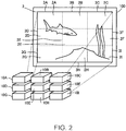
- Fig. 2 shows a state in which the projection areas other than the projection area 3A (projection areas 3B to 31) have been adjusted with direct or indirect reference to the projection area 3A.
- Fig. 3 diagrammatically shows the projector 10A.
- the projector 10A includes an operation section 110, an image processing section 120, a light valve driver 130, a light source driver 140, a projection section 150, a lens driver 160, a lens shifter 170, an imaging section 180, a communication section 190, a storage section 210, a control section 220, and a bus 230.
- the projection section 150 includes a light source 151, three liquid crystal light valves 152 (152R, 152G, and 152B), which are an example of a light modulator, and a projection system 153.
- the projectors 10A to 10I have the same configuration.
- the projectors 10B to 10I therefore each include the operation section 110, the image processing section 120, the light valve driver 130, the light source driver 140, the projection section 150, the lens driver 160, the lens shifter 170, the imaging section 180, the communication section 190, the storage section 210, the control section 220, and the bus 230, as does the projector 10A.
- the operation section 110, the image processing section 120, the light valve driver 130, the light source driver 140, the lens driver 160, the lens shifter 170, the imaging section 180, the communication section 190, the storage section 210, and the control section 220 can communicate with each other via the bus 230.
- the operation section 110 is formed, for example, of a variety of operation buttons or operation keys or a touch panel.
- the operation section 110 receives the user's input operation.
- the operation section 110 may, for example, be a remote control that transmits information according to the user's input operation wirelessly or via a wire.
- the projector 10A includes a receiver that receives the information transmitted by the remote control.
- the remote control includes a variety of operation buttons or operation keys or a touch panel that receives the user's input operation.
- the image processing section 120 performs image processing on image information to produce an image signal.
- the image processing section 120 performs image processing on image information received from an image supply apparatus, such as a personal computer (PC), to produce an image signal.
- an image supply apparatus such as a personal computer (PC)
- the light valve driver 130 drives the liquid crystal light valves 152 (152R, 152G, and 152B) based on the image signal produced by the image processing section 120.
- the light source driver 140 drives the light source 151. For example, when the operation section 110 receives "power-on operation," the light source driver 140 causes the light source 151 to emit light.
- the projection section 150 projects a projection image (partial image 2A) on the projection surface 100.
- the projection system 153 includes a zoom lens 153a and a projection lens 153b.
- the optical axis of the zoom lens 153a coincides with the optical axis of the projection lens 153b.
- an "optical axis 153c" represents the optical axis of the zoom lens 153a and the optical axis of the projection lens 153b.
- the liquid crystal light valves 152 modulate the light emitted from the light source 151 to form projection image light (partial image light), and the projection system 153 enlarges and projects the projection image light.
- the light source 151 is a xenon lamp, an ultrahigh-pressure mercury lamp, a light emitting diode (LED), a laser light source, or any other light source.
- the light emitted from the light source 151 passes through an optical integration system that is not shown, which reduces variation in the luminance distribution of the light, and the resultant light is then separated by a color separation system that is not shown into color light components of red (R), green (G), and blue (B), which are the three primary colors of light.
- the RGB color light components are incident on the liquid crystal light valves 152R, 152G, and 152B, respectively.
- the liquid crystal light valves 152 are each formed, for example, of a liquid crystal panel in which a pair of transparent substrates encapsulate a liquid crystal material.
- a rectangular pixel area 152a which is formed of a plurality of pixels 152p arranged in a matrix, is formed in each of the liquid crystal light valves 152.
- drive voltage is applicable to the liquid crystal material for each of the pixels 152p.
- the light valve driver 130 applies drive voltage according to the image signal inputted from the image processing section 120 to each of the pixels 152p, and the pixel 152p has optical transmittance set in accordance with the image signal.
- the light emitted from the light source 151 is therefore modulated when passing through the pixel areas 152a to form images according to the image signal (image information) on a color basis.
- the color images are combined with one another by a light combining system that is not shown for each of the pixels 152p into projection image light (partial image 2A) that is color image light (color image).
- the projection system 153 enlarges the partial image 2A and projects the enlarged partial image 2A on the projection surface 100.
- the light source driver 140 drives the light source 151. For example, when the operation section 110 receives "power-on operation," the light source driver 140 causes the light source 151 to emit light.
- the lens driver 160 can change the zooming state of the zoom lens 153a.
- the lens driver 160 moves the zoom lens 153a in a direction G along the optical axis 153c to change the zooming state of the zoom lens 153a.
- the size of the projection area 3A on the projection surface 100 changes in accordance with the zooming state of the zoom lens 153a.
- the lens shifter 170 can shift the projection system 153 in a direction H, which intersects the optical axis 153c (direction perpendicular to optical axis 153c, for example) .
- the lens shifter 170 can further shift the projection system 153 in the direction perpendicular both to the optical axis 153c and the direction H.
- the position of the projection area 3A on the projection surface 100 changes in accordance with the shift state of the projection system 153.
- the imaging section 180 captures an image of the projection surface 100 to produce captured image information representing the captured image.
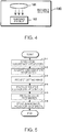
- Fig. 4 shows an example of the imaging section 180.
- the imaging section 180 is a camera including an optical system 181, such as a lens, an imaging device 182, which converts light collected by the optical system 181 into an electric signal, and other components.
- the imaging device 182 is, for example, a CCD (charge coupled device) image sensor or a CMOS (complementary metal oxide semiconductor) image sensor.
- the communication section 190 can communicate, for example, with another projector via a wire or wirelessly.
- the storage section 210 is a computer readable recording medium.
- the storage section 210 stores a program that specifies the action of the projector 10A and a variety of pieces of information.
- the control section 220 is a computer, such as a CPU (central processing unit).
- the control section 220 may be formed of one or more processors.
- the control section 220 reads and executes the program stored in the storage section 210 to achieve an adjustment mode control section 221, a subordinate projector information management section 222, an adjustment instruction section 223, and an adjustment control section 224.
- the control section 220 formed of one or more processors may instead achieve the adjustment mode control section 221, the subordinate projector information management section 222, the adjustment instruction section 223, and the adjustment control section 224.
- the adjustment mode control section 221 controls an adjustment mode of the projector 10A.
- the adjustment mode control section 221 alternatively sets a "main projector mode” and a "subordinate projector mode” as the adjustment mode.
- the "main projector mode” is hereinafter also referred to as a “main mode, " and the "subordinate projector mode” is hereinafter also referred to as a "subordinate mode.”
- the adjustment mode is the "main mode”
- the projector 10A acts as the main projector.
- the adjustment mode is the "subordinate mode”
- the projector 10A acts as a subordinate projector.
- the adjustment mode is set at the "subordinate mode” as a default.
- the adjustment mode control section 221 sets the adjustment mode to be the "main mode.”
- the subordinate projector information management section 222 acts in the case where the adjustment mode is the "main mode.”
- the subordinate projector information management section 222 stores information on the subordinate projectors (hereinafter also referred to as "subordinate projector information") in the storage section 210.
- the subordinate projector information contains communication information necessary for the communication between the main projector and each subordinate projector, a relative relationship information representing a target relative relationship among the projection areas 3A to 3I (relative positional relationship and relative size relationship), and a color information representing the colors of the partial images 2A to 2I in the adjustment.
- the communication information is, for example, an IP (Internet protocol) address of each subordinate projector.
- the communication information may be obtained by the subordinate projector information management section 222 from the network or may be inputted by the user via the operation section 110.
- the relative relationship information is produced based on information inputted by the user via the operation section 110.
- the color information may be inputted by the user via the operation section 110 or may be produced by the subordinate projector information management section 222 based on the relative relationship information.
- the color information is so set that the colors of adjacent ones of the partial images 2A to 2I on the projection surface 100 differ from each other.
- the adjustment instruction section 223 acts in the case where the adjustment mode is the "main mode.”
- the adjustment instruction section 223 uses the subordinate projector information to produce the adjustment instructions described above on a subordinate projector basis.
- the adjustment instructions each include reference information, specifying information, relativity information, a position adjustment instruction, and a size adjustment instruction.
- the reference information is information for identifying a partial image that serves as the adjustment reference (hereinafter also referred to as "reference partial image").
- the reference information represents at least the color of the reference partial image.
- the reference information may represent the color of the reference partial image, the color of an adjusted partial image that is in contact with the reference partial image, and the positional relationship between the adjusted partial image and the reference partial image.
- the adjustment instruction section 223 produces the reference information by using the color information and the relative relationship information stored in the storage section 210.
- the specifying information specifies the color of a partial image to be projected by a subordinate projector having received the adjustment instruction (hereinafter also referred to as "adjustment partial image").
- the color of an adjustment partial image specified by the specifying information differs from the color of the reference partial image indicated by the reference information.
- the adjustment instruction section 223 uses the color information stored in the storage section 210 to produce the specifying information.
- the relativity information represents the relative positional relationship and the relative size relationship between the reference partial image projection area and an adjustment partial image target projection area.
- the relative positional relationship may, for example, be the relationship representing the situation in which an adjustment partial image target projection area is on the right of the reference partial image projection area.
- the relative positional relationship is not limited to the relationship representing the situation in which an adjustment partial image target projection area is on the right of the reference partial image projection area and can be changed as appropriate.
- the relative size relationship may, for example, be the relationship representing the situation in which the size of the reference partial image is equal to the size of the adjustment partial image.
- the relative size relationship is not limited to the relationship representing the situation in which the size of the reference partial image is equal to the size of the adjustment partial image and can be changed as appropriate.
- the adjustment instruction section 223 uses the relative relationship information stored in the storage section 210 to produce the relativity information.
- the position adjustment instruction is an instruction of adjusting the position of an adjustment partial image projection area based on the position of the reference partial image projection area.
- the size adjustment instruction is an instruction of adjusting the size of the adjustment partial image projection area based on the size of the reference partial image projection area.
- the adjustment instruction section 223 produces the position adjustment instruction and the size adjustment instruction in accordance with an instruction received by the operation section 110.
- the adjustment instruction section 223 causes the adjustment instruction to contain the position adjustment instruction and the size adjustment instruction.
- the adjustment instruction section 223 causes the adjustment instruction to contain the position adjustment instruction but no size adjustment instruction.
- the adjustment instruction section 223 causes the adjustment instruction to contain the size adjustment instruction but no position adjustment instruction.
- the reference information is an example of first specific information
- the specifying information is an example of first specifying information
- the relativity information is an example of first relative positional information
- the position adjustment instruction is an example of first position adjustment instruction
- the size adjustment instruction is an example of first size adjustment instruction.
- the position adjustment instruction is an example of second position adjustment instruction and the size adjustment instruction is an example of second size adjustment instruction.
- the adjustment instruction section 223 uses the communication information stored in the storage section 210 to transmit the adjustment instructions to the subordinate projectors via the communication section 190.
- the adjustment instruction section 223 first transmits the adjustment instructions to the projectors 10B and 10D. Having transmitted the adjustment instructions to the projectors 10B and 10D, in more detail, after reception of completion notice that will be described later from each of the projectors 10B and 10D, the adjustment instruction section 223 transmits the adjustment instructions to the projectors 10C, 10E, and 10G. After reception of completion notice that will be described later from each of the projectors 10C, 10E, and 10G, the adjustment instruction section 223 transmits the adjustment instructions to the projectors 10F and 10H. After reception of completion notice that will be described later from each of the projectors 10F and 10H, the adjustment instruction section 223 transmits the adjustment instruction to the projector 10I.
- the adjustment instruction section 223 starts the transmission of the adjustment instructions after the projection section 150 projects the partial image 2A having a color specified by the color information stored in the storage section 210.
- the adjustment control section 224 acts in the case where the adjustment mode is the "subordinate mode.”
- the adjustment control section 224 receives the adjustment instruction from the main projector via the communication section 190.
- the adjustment control section 224 adjusts the relative relationship between the reference partial image projection area and the projection area 3A, where the partial image 2A is projected, in accordance with the adjustment instruction received from the main projector.
- the adjustment control section 224 causes the projection section 150 to project the partial image 2A having a color specified by the specifying information contained in the adjustment instruction and subsequently causes the imaging section 180 to capture an image of the projection surface 100 to produce captured image information.
- the adjustment control section 224 preferably adjusts the zooming function of the imaging section 180 in such a way that the projection surface 100 is enlarged in the captured image indicated by the captured image information. The reason for this is that the difficulty in precisely identifying the size and position of a partial image in a captured image increases as the size of the projection surface 100 shown in a captured image decreases.
- the adjustment control section 224 identifies the actual relative relationship between the reference partial image identified by the reference information contained in the adjustment instruction and the adjustment partial image (partial image 2A) based on the captured image information.
- the adjustment control section 224 controls the lens shifter 170 to cause it to shift the projection system 153 in such a way that the actual positional relationship between the reference partial image and the adjustment partial image is equal to the relative positional relationship indicated by the relativity information.
- the adjustment control section 224 controls the lens driver 160 to cause it to change the position of the zoom lens 153a in such a way that the actual size relationship between the reference partial image and the adjustment partial image is equal to the relative size relationship indicated by the relativity information.
- Fig. 5 is a flowchart for primarily describing the action of the subordinate projector information management section 222 of the main projector 10A, specifically, how the subordinate projector information management section 222 acquires the communication information, produces the relative relationship information, and produces the color information.
- the subordinate projector information management section 222 searches for subordinate projectors in the network to which the projector 10A is connected (step S11).
- the subordinate projector information management section 222 subsequently acquires the communication information (IP address of subordinate projector) from each subordinate projector found in the search (step S12).
- the subordinate projector information management section 222 subsequently prompts the user to set a target relative relationship among the projection areas 3A to 3I (hereinafter referred to as "target relationship").
- the subordinate projector information management section 222 causes the projection section 150 to project a setting image for setting the target relationship (step S13). Specifically, the subordinate projector information management section 222 outputs setting image information representing a setting image to the image processing section 120 to cause the projection section 150 to project the setting image.
- Fig. 6 shows an example of a setting image 222a.
- the setting image 222a shown in Fig. 6 is used in a case where the target relationship is set in a situation in which the nine projection areas 3A to 3I are so arranged as to be adjacent to each other in three vertical columns and three horizontal rows (3 ⁇ 3).
- symbols (3A to 31) with which the projection areas are labeled are used as information for identifying the projection areas, but the information for identifying the projection areas is not limited thereto, and may, for example, be information that identifies a projector that projects a partial image in each of the projection areas (projector name, for example).
- the user operates the operation section 110 while looking at the setting image 222a to set the arrangement of the nine projection areas in the three vertical columns and three horizontal rows.
- the user operates the operation section 110 to change the arrangement shown in Fig. 6 (for example, swap the position of the projection area 3B and the position of the projection area 3C) to set the arrangement of the nine projection areas in the three vertical columns and three horizontal rows.
- the user operates the operation section 110 while looking at the setting image 222a to set the relative size relationship among the nine projection areas.
- the nine projection areas 3A to 3I have the same size and shape.
- the user operates the operation section 110 to set the relative size relationship among the nine projection areas 3A to 3I shown in Fig. 6 .
- the subordinate projector information management section 222 produces the relative relationship information representing the target relationship set by using the setting image 222a (step S14). It is assumed in the following description that the relative relationship information representing the arrangement and the size relationship shown in Fig. 6 has been produced.
- the subordinate projector information management section 222 subsequently produces the color information by referring to the relative relationship information (step S15) .
- the subordinate projector information management section 222 produces the color information in such a way that partial images adjacent to each other on the projection surface 100 have difference colors.
- color information 222b representing the relationship shown in Fig. 7 has been produced.
- the subordinate projector information management section 222 produces color information representing that the partial images 2A, 2E, and 2I are drawn in red, the partial images 2C, 2D, and 2H are drawn in green, and the partial images 2B, 2F, and 2G are drawn in blue.
- the color information 222b may represent a color relationship different from the relationship shown in Fig. 7 .
- the subordinate projector information management section 222 subsequently stores the communication information acquired in step S12, the relative relationship information produced in step S14, and the color information produced in step S15 as the subordinate projector information in the storage section 210 (step S16) .
- the user Having completed the setting of the target relationship by using, for example, the setting image 222a shown in Fig. 6 , the user roughly adjusts the positions of the projectors 10A to 10I to cause the relative relationship among the projection areas 3A to 3I to approach the target relationship shown in Fig. 6 .
- the user subsequently adjusts the main projector 10A with high precision to cause the projection area 3A, where the partial image 2A is projected, to coincide with the target projection area.
- the user subsequently operates the operation section 110 to input an adjustment start instruction to the projector 10A.
- the adjustment instruction section 223 starts acting in response to the input of the adjustment start instruction.
- Fig. 8 is a flowchart for primarily describing the action of the adjustment instruction section 223 in the main projector 10A.
- the adjustment instruction section 223 first refers to the color information stored in the storage section 210 and causes the projection section 150 to project the partial image 2A having the color that the color information represents as the color of the partial image 2A, specifically, red (entirely red partial image) (step S21). Since the projection area of the partial image 2A has been adjusted by the user, the partial image 2A is projected in the target projection area 3A.
- the adjustment instruction section 223 subsequently determines the reference partial image (step S22). In a case where step S21 is followed by step S22, the adjustment instruction section 223 determines the partial image 2A projected in the target projection area 3A to be the reference partial image.
- the adjustment instruction section 223 subsequently refers to the relative relationship information stored in the storage section 210 and determines a partial image adjacent to the reference partial image out of partial images not having been adjusted as an adjustment partial image (step S23). In the case where the reference partial image is the partial image 2A, the adjustment instruction section 223 determines the partial images 2B and 2D as the adjustment partial image.
- the adjustment instruction section 223 subsequently determines the subordinate projector that projects the adjustment partial image as an adjustment projector (step S24) .
- the adjustment instruction section 223 determines the subordinate projectors 10B and 10D to be the adjustment projector.
- the adjustment instruction section 223 subsequently refers to the subordinate projector information stored in the storage section 210 and produces the adjustment instructions for the adjustment projectors (step S25).
- step S25 the adjustment instruction section 223 produces, as the adjustment instruction for the subordinate projector 10B, an adjustment instruction containing reference information representing red, specifying information specifying blue, relativity information showing that the position of the adjustment partial image is on the right of the position of the red image and the size of the adjustment partial image is equal to the size of the red image, a position adjustment instruction, and a size adjustment instruction.
- the adjustment instruction section 223 further produces, as the adjustment instruction for the subordinate projector 10D, an adjustment instruction containing reference information representing red, specifying information specifying green, relativity information showing that the position of the adjustment partial image is below the position of the red image and the size of the adjustment partial image is equal to the size of the red image, a position adjustment instruction, and a size adjustment instruction.
- the adjustment instruction section 223 subsequently transmits the adjustment instructions via the communication section 190 to the adjustment projectors (step S26).
- the adjustment instruction section 223 transmits the adjustment instructions to the subordinate projectors 10B and 10D via the communication section 190.
- Fig. 9 is a flowchart for describing the action of each of the adjustment projectors that adjust the partial image projection areas in accordance with an adjustment instructions.
- the adjustment control section 224 when it receives the adjustment instruction via the communication section 190, causes the projection section 150 to project a partial image having a color specified by the specifying information contained in the adjustment instruction (adjustment partial image) (step S31) .
- the adjustment control section 224 outputs image information representing the adjustment partial image to the image processing section 120 to cause the projection section 150 to project the adjustment partial image.
- the projector 10B that is one of the adjustment projectors projects the partial image 2B entirely drawn in blue, and the projector 10D that is the other adjustment projector projects the partial image 2D entirely drawn in green.
- the adjustment control section 224 subsequently causes the imaging section 180 to capture an image of the projection surface 100 (step S32). Having captured an image of the projection surface 100, the imaging section 180 produces captured image information representing a captured image containing the red partial image 2A, the blue partial image 2B, and the green partial image 2D.
- the adjustment control section 224 subsequently uses the captured image information and the adjustment instruction to adjust the projection area of the adjustment partial image (step S33).
- the adjustment control section 224 identifies the reference partial image, which is identified by the reference information contained in the adjustment instruction, in the captured image.
- the adjustment control section 224 further identifies as the adjustment partial image the partial image having the color specified by the specifying information contained in the adjustment instruction in the captured image.
- the adjustment control section 224 identifies as the adjustment partial image, for example, a partial image closest to the reference partial image out of the plurality of partial images having the color specified by the specifying information.
- the adjustment performed by the projector 10B which is one of the adjustment projectors, will first be described.
- the adjustment control section 224 identifies as the reference partial image the partial image 2A drawn in red indicated by the reference information in the captured image.
- the adjustment control section 224 subsequently identifies as the adjustment partial image the partial image 2B drawn in blue specified by the specifying information in the captured image.
- the adjustment control section 224 subsequently adjusts the projection area 3B of the adjustment partial image to reduce the difference between the relationship between the adjustment partial image and the reference partial image in the captured image and the relationship indicated by the relativity information (the adjustment partial image is on the right of the red image and has the same size of red image).
- the adjustment control section 224 adjusts the position of the zoom lens 153a by using the lens driver 160 to reduce the difference in size between the adjustment partial image (partial image 2B) and the reference partial image (partial image 2A).
- the adjustment control section 224 uses the number of pixels that form each of the images as the size of the image.
- the adjustment control section 224 moves the zoom lens 153a to make the adjustment partial image smaller on the projection surface 100.
- the adjustment control section 224 moves the zoom lens 153a to make the adjustment partial image larger on the projection surface 100.
- the adjustment control section 224 adjust the position of the projection system 153 by using the lens shifter 170 to cause the position of the adjustment partial image to be on the right of the reference partial image.
- the adjustment control section 224 moves the projection system 153 in such a way that the coordinates (pixel coordinates) of the upper left corner of the adjustment partial image is on the right of the coordinates (pixel coordinates) of the upper right corner of the reference partial image and the coordinates of the lower left corner of the adjustment partial image is on the right of the coordinates (pixel coordinates) of the lower right corner of the reference partial image.
- the adjustment control section 224 causes the imaging section 180 to capture an image of the projection surface 100 again and uses captured image information produced by the re-image-capturing to adjust the adjustment partial image described above.
- the adjustment control section 224 repeats the adjustment described above until the position of the zoom lens 153a and the position of the projection system 153 each converge.
- the adjustment control section 224 uses the communication section 190 to transmit completion notice indicating that the projection area 3B of the partial image 2B has been adjusted in accordance with the adjustment instruction to the main projector 10A (step S34) .
- Steps S31 to S34 shown in Fig. 9 are carried out also in the projector 10D, which is the other adjustment projector.
- the adjustment instruction section 223 evaluates whether or not the projector 10A has received the completion notice from all projectors to which the adjustment instructions had been transmitted (step S27). In the case where the projector 10A has received the completion notice from all the projectors to which the adjustment instructions had been transmitted (YES in step S27), the adjustment instruction section 223 evaluates whether or not the projector 10A has transmitted the adjustment instructions to all the subordinate projectors (step S28) . In a case where the projector 10A has not transmitted the adjustment instructions to all the subordinate projectors (NO in step S28), the adjustment instruction section 223 returns to the process in step S22.
- the adjustment instruction section 223 sets the partial image determined to be the adjustment partial image last time as the reference partial image (step S22). For example, in a case where the partial images 2B and 2D were determined as the adjustment partial image last time, the adjustment instruction section 223 sets the partial images 2B and 2D to be the reference partial image.
- the adjustment instruction section 223 then carries out steps S23 and S24.
- the adjustment instruction section 223 determines the partial images 2C, 2E, and 2G to be the adjustment partial images in step S23 and determines the projectors 10C, 10E, and 10G to be the adjustment projectors in step S24.
- the adjustment instruction section 223 subsequently produces adjustment instructions in step S25.
- the reference partial image is the partial image 2A (red) and the adjustment partial image is formed of the partial images 2B (blue) and 2D (green), as described above, there is no adjustment partial image having the same color of the reference partial image. Therefore, even in a case where the reference information contained in the adjustment instructions shows only the color of the reference partial image, the reference partial image is uniquely identified by the reference information.
- the reference partial image is formed of the partial images 2B (blue) and 2D (green)
- the adjustment partial image is formed of the partial images 2C (green), 2E (red), and 2G (blue)
- there is an adjustment partial image having the same color of the reference partial image there is an adjustment partial image having the same color of the reference partial image.
- the reference information shows only the color of the reference partial image, it is difficult to uniquely identify the reference partial image only by the reference information.
- the adjustment instruction section 223 produces, as the reference information contained in the adjustment instructions, information representing the color of the reference partial image, the color of an adjusted partial image in contact with the reference partial image, and the positional relationship between the adjusted partial image and the reference partial image.
- the adjustment instruction section 223 produces, as the reference information contained in the adjustment instructions, information representing the color of the reference partial image 2B (blue), the color of the adjusted partial image 2A (red) in contact with the reference partial image 2B, and the positional relationship representing that the reference partial image 2B is on the right of the adjusted partial image 2A.
- the thus produced reference information allows identification of the reference partial image that is not the partial image 2G (blue) but is the partial image 2B (blue).
- the adjustment instruction section 223 subsequently carries out step S26 to transmit the adjustment instructions to the adjustment projectors via the communication section 190.
- the adjustment projectors when they receive the adjustment instructions, each carry out steps S31 to S34 shown in Fig. 9 . as described above.
- the captured image shows a situation in which there are a plurality of partial images having a color specified by the specifying information.
- the partial images 2A (red), 2B (blue), 2C (green), 2D (green), 2E (red), and 2G (blue) are projected on the projection surface 100. Therefore, as for the projector 10C, which is one of the adjustment projectors, the captured image shows a situation in which there are two partial images drawn in green specified by the specifying information (partial images 2C and 2D).
- step S33 the adjustment partial image associated with the projector 10C is identified in step S33 as follows.
- the adjustment control section 224 identifies an adjustment partial image candidate closest to the reference partial image as the adjustment partial image out of the plurality of adjustment partial image candidates.
- One adjustment partial image can therefore be identified in step S33.
- the adjustment instruction section 223 evaluates whether or not a predetermined period has elapsed since the transmission of the last adjustment instruction (step S29). In a case where the predetermined period has not elapsed since the transmission of the last adjustment instruction (NO in step S29), the adjustment instruction section 223 returns to the process in step S27.
- the adjustment instruction section 223 outputs image information representing an error display image to the image processing section 120 to cause the projection section 150 to project the error display image on the projection surface 100 (step S30).
- the adjustment instruction section 223 subsequently transmits an adjustment termination instruction to all the subordinate projectors.
- the adjustment control section 224 of each of the subordinate projectors when it receives the adjustment termination instruction, terminates the projection according to the adjustment instruction (projection of partial image having color specified by specifying information).
- the adjustment instruction section 223 transmits the adjustment termination instruction to all the subordinate projectors and then terminates the actions shown in Fig. 8 .
- the projector 10A, the multi-projection system 1, and the method for controlling the projector 10A according to the present embodiment allow adjustment of the projection areas of the partial images projected by the plurality of subordinate projectors based directly or indirectly on the projection area of the partial image projected by the projector 10A.
- the user's adjustment of the projection area of the partial image projected by the projector 10A allows automatic adjustment of the other projection areas based on the adjusted projection area.
- the effort of the adjustment of the projection areas can therefore be reduced as compared with a case where the user adjusts all the projection areas.
- the target projection areas 3A to 3I set through the setting image 222a may be so configured that those adjacent to each other may be in contact with each other as described above or may partially overlap with each other.
- the adjustment control section 224 identifies the area having the color different from the colors of the partial images as a portion where the partial images overlap with each other and adjusts an adjustment partial image based on the result of the identification.
- edge blending is a technology for causing adjacent projection areas to partially overlap with each other and reducing the brightness of the overlapping portion so that the joint between the partial images is unlikely to be recognized.
- the user may first manually adjust a projection area (projection area where subordinate projector projects partial image) adjacent to the projection area where the main projector projects a partial image to set the amount of overlapping, and another subordinate projector may adjust the projection area with reference to the set amount of overlapping.
- a projection area projection area where subordinate projector projects partial image
- another subordinate projector may adjust the projection area with reference to the set amount of overlapping.
- the number of projectors that forms the multi-projection system 1 is not limited to nine and only needs to be at least three.
- the arrangement of a plurality of projection areas is not limited to be formed of the three vertical columns and three horizonal rows and can be changed as appropriate.
- the projector that serves as the main projector is not limited to the projector corresponding to the projection area at an end of a target projection area arrangement.
- the projector 10E corresponding to the projection area 3E may be the main projector.
- the colors of the partial images indicated by the color information are not limited to the colors of the partial images shown in Fig. 7 , and the colors of partial images adjacent to each other on the projection surface 100 only need to differ from each other. Therefore, for example, the color of a partial image projected by the main projector is not necessarily red and may, for example, be blue or green.
- the color specified by the specifying information is used to distinguish the partial image from others .
- the color specified by the specifying information is therefore preferably one selected from red, blue, and green, which greatly differ from one another in terms of the color component thereof.
- the color specified by the specifying information may be a color other than red, blue, and green.
- the adjustment control section 224 may cause the projection section 150 to project information that prompts the user to move the projector (for example, image information representing letters that stand for "Move projector.” In this case, the adjustment control section 224 may also cause the projection section 150 to project information representing the direction in which the projector is moved. In this case, the adjustment control section 224 identifies the direction in which the projector is moved based on the captured image.
- control section 220 executes the program may be achieved by hardware formed, for example, of a field programmable gate array (FPGA), an application specific IC (ASIC), or any other electronic circuit or may be achieved by software and hardware that cooperate with each other.
- FPGA field programmable gate array
- ASIC application specific IC
- liquid crystal light valves are used as the light modulator, but the light modulator is not limited to liquid crystal light valves and can be changed as appropriate.
- the light modulator may instead be configured to use three reflective liquid crystal panels.
- the light modulator may still instead, for example, be configured to use one liquid crystal panel combined with a color wheel, three digital mirror devices (DMDs), or one digital mirror device combined with a color wheel.
- DMDs digital mirror devices
- no members corresponding to the color separation system and the light combining system are required.
- a configuration including no liquid crystal panel or DMD but capable of modulating the light emitted by the light source can be employed as the light modulator.
Landscapes
- Physics & Mathematics (AREA)
- General Physics & Mathematics (AREA)
- Engineering & Computer Science (AREA)
- Multimedia (AREA)
- Signal Processing (AREA)
- Geometry (AREA)
- Controls And Circuits For Display Device (AREA)
- Transforming Electric Information Into Light Information (AREA)
- Projection Apparatus (AREA)
- Video Image Reproduction Devices For Color Tv Systems (AREA)
Abstract
Description
- The present invention relates to a projector, a multi-projection system, and a method for controlling the projector.
-
JP-T-2009-524841 - In the multi-projection system, projection areas of the plurality of partial images need to be so precisely adjusted that the plurality of partial images form the overall image, and the adjustment is made by a user of the multi-projection system. The adjustment of the projection areas therefore requires the user's effort.
- An advantage of some aspects of the invention is to provide a technology capable of lightening effort spent on adjustment of projection areas.
- An aspect of a projector according to the invention is directed to a projector that is allowed to belong to a multi-projection system that projects an image on a projection surface, the image formed of a plurality of partial images including a first partial image, a second partial image, and a third partial image, the projector including a projection section that projects the third partial image on the projection surface and an adjustment instruction section that transmits, to a first projector that projects the first partial image, a first adjustment instruction of adjusting a projection area of the first partial image based on a projection area of the third partial image and transmits, to a second projector that projects the second partial image after transmitting the first adjustment instruction, a second adjustment instruction of adjusting a projection area of the second partial image based on the projection area of the first partial image.
- The aspect described above allows adjustment of the projection areas of the first and second partial images based directly or indirectly on the projection area of the third partial image. Therefore, for example, a user's adjustment of the projection area of the third partial image allows adjustment of the projection areas of the first and second partial images based on the adjusted projection area of the third partial image. The effort of the adjustment of the projection areas can therefore be reduced as compared with a case where the user adjusts all the projection areas of the first to third partial images.
- In the aspect of the projector described above, it is desirable that the adjustment instruction section transmits the second adjustment instruction to the second projector when the adjustment instruction section receives from the first projector completion notice indicating that the adjustment of the projection area of the first partial image has been completed in accordance with the first adjustment instruction.
- According to the aspect described above, the adjustment of the projection area of the second partial image is performed after the adjustment of the projection area of the first partial image is completed. The projection areas of the first and second partial images adjusted based directly or indirectly on the projection area of the third partial image . Therefore, for example, the user's adjustment of the projection area of the third partial image allows adjustment of the projection areas of the first and second partial images based on the adjusted projection area of the third partial image. The effort of the adjustment of the projection areas can therefore be reduced as compared with the case where the user adjusts all the projection areas of the first to third partial images.
- In the aspect of the projector described above, it is desirable that the first adjustment instruction contains a first position adjustment instruction of adjusting a position of the projection area of the first partial image based on a position of the projection area of the third partial image.
- According to the aspect described above, the position of the projection area of the first partial image can be adjusted based on the position of the projection area of the third partial image.
- In the aspect of the projector described above, it is desirable that the first adjustment instruction further contains first specific information for identifying the third partial image and first relative position information representing a relative positional relationship between the projection area of the third partial image and a target projection area of the first partial image.
- According to the aspect described above, the first projector can identify the third partial image by using the first specific information. The first projector can adjust the projection area of the first partial image to the target projection area of the first partial image by using the projection area of the third partial image identified by using the first specific information and the first relative positional information.
- In the aspect of the projector described above, it is desirable that the first specific information represents a color of the third partial image.
- According to the aspect described above, the first projector can identify the third partial image based on the color of the third partial image.
- In the aspect of the projector described above, it is desirable that the first adjustment instruction further contains first specifying information that specifies a color different from the color of the third partial image as the color of the first partial image.
- According to the aspect described above, the first projector can distinguish the first and third partial images from each other in terms of color. The first projector can therefore recognize the relative relationship between the first and third partial images.
- In the aspect of the projector described above, it is desirable that the first adjustment instruction contains a first size adjustment instruction of adjusting a size of the projection area of the first partial image based on a size of the projection area of the third partial image.
- According to the aspect described above, the size of the projection area of the first partial image can be adjusted based on the size of the projection area of the third partial image.
- In the aspect of the projector described above, it is desirable that the second adjustment instruction contains a second position adjustment instruction of adjusting a position of the projection area of the second partial image based on a position of the projection area of the first partial image.
- According to the aspect described above, the position of the projection area of the second partial image can be adjusted based on the position of the projection area of the first partial image.
- In the aspect of the projector described above, it is desirable that the second adjustment instruction contains a second size adjustment instruction of adjusting a size of the projection area of the second partial image based on a size of the projection area of the first partial image.
- According to the aspect described above, the size of the projection area of the second partial image can be adjusted based on the size of the projection area of the first partial image.
- In the aspect of the projector described above, it is desirable that a target projection area of the first partial image is in contact with or partly overlaps with the projection area of the third partial image.
- According to the aspect described above, the projection area of the third partial image in contact with the target projection area of the first partial image or the projection area of the third partial image that partly overlaps with the target projection area of the first partial image can be used to adjust the first partial image. Therefore, for example, in a case where the first projector captures an image of both the third and first partial images with a camera to produce captured image information and the captured image information is used to adjust the first partial image, the captured area can be reduced as compared with a case where the third and first partial images are separate from each other.
- In the aspect of the projector described above, it is desirable that a target projection area of the second partial image is in contact with or partly overlaps with the projection area of the first partial image.
- According to the aspect described above, the projection area of the first partial image in contact with the target projection area of the second partial image or the projection area of the first partial image that partly overlaps with the target projection area of the second partial image can be used to adjust the second partial image. Therefore, for example, in a case where the second projector captures an image of both the first and second partial images with a camera to produce captured image information and the captured image information is used to adjust the second partial image, the captured area can be reduced as compared with a case where the first and second partial images are separate from each other.
- In the aspect of the projector described above, it is desirable that the plurality of partial images include the third partial image, a plurality of fourth partial images, and a plurality of fifth partial images, that the first partial image is any of the plurality of fourth partial images, that the second partial image is any of the plurality of fifth partial images, and that the adjustment instruction section transmits, for each of the fourth partial images to a third projector that is a projector that projects the fourth partial image, a third adjustment instruction of adjusting a projection areas of the fourth partial image projected by the third projector based on the projection area of the third partial image, and after transmission of the third adjustment instruction, transmits, for each of the fifth partial images to a fourth projector that is a projector that projects the fifth partial image, a fourth adjustment instruction of adjusting a projection areas of the fifth partial image projected by the fourth projector based on any of the fourth partial images.
- The aspect described above allows adjustment of the projection areas of the plurality of fourth partial images and the projection areas of the plurality of fifth partial images based directly or indirectly on the projection area of the third partial image.
- An aspect of a multi-projection system according to the invention is directed to a multi-projection system that projects an image on a projection surface, the image formed of a plurality of partial images including a first partial image, a second partial image, and a third partial image, the multi-projection system including a first projector that projects the first partial image on the projection surface, a second projector that projects the second partial image on the projection surface, and a third projector that projects the third partial image on the projection surface. The third projector transmits to the first projector a first adjustment instruction of adjusting a projection area of the first partial image based on a projection area of the third partial image, and the first projector adjusts the projection area of the first partial image based on the projection area of the third partial image in accordance with the first adjustment instruction. The third projector, after transmitting the first adjustment instruction, transmits to the second projector a second adjustment instruction of adjusting a projection area of the second partial image based on the projection area of the first partial image, and the second projector adjusts the projection area of the second partial image based on the projection area of the first partial image in accordance with the second adjustment instruction.
- The aspect described above allows adjustment of the projection areas of the first and second partial images based directly or indirectly on the projection area of the third partial image. Therefore, for example, a user's adjustment of the projection area of the third partial image allows adjustment of the projection areas of the first and second partial images based on the adjusted projection area of the third partial image. The effort of the adjustment of the projection areas can therefore be reduced as compared with a case where the user adjusts all the projection areas of the first to third partial images.
- An aspect of a method for controlling a projector according to the invention is directed to a method for controlling a projector that is allowed to belong to a multi-projection system that projects an image on a projection surface, the image formed of a plurality of partial images including a first partial image, a second partial image, and a third partial image, the method including projecting the third partial image on the projection surface, transmitting, to a first projector that projects the first partial image, a first adjustment instruction of adjusting a projection area of the first partial image based on a projection area of the third partial image, and transmitting, to a second projector that projects the second partial image after transmitting the first adjustment instruction, a second adjustment instruction of adjusting a projection area of the second partial image based on the projection area of the first partial image.
- The aspect described above allows adjustment of the projection areas of the first and second partial images based directly or indirectly on the projection area of the third partial image.
- Therefore, for example, a user's adjustment of the projection area of the third partial image allows adjustment of the projection areas of the first and second partial images based on the adjusted projection area of the third partial image.
- The effort of the adjustment of the projection areas can therefore be reduced as compared with a case where the user adjusts all the projection areas of the first to third partial images.
- The invention will be described with reference to the accompanying drawings, wherein like numbers reference like elements.
-
Fig. 1 shows a multi-projection system including projectors according to a first embodiment. -
Fig. 2 shows a state in which projection areas other than a reference projection area have been adjusted with reference to the reference projection area. -
Fig. 3 diagrammatically shows one of the projectors. -
Fig. 4 shows an example of an imaging section. -
Fig. 5 is a flowchart for primarily describing the action of a subordinate projector information management section. -
Fig. 6 shows an example of a setting image. -
Fig. 7 shows an example of color information. -
Fig. 8 is a flowchart for primarily describing the action of an adjustment instruction section. -
Fig. 9 is a flowchart for describing the action of an adjustment projector. - Embodiments according to the invention will be described below with reference to the drawings. In the drawings, the dimension and scale of each portion differ from actual values as appropriate. Further, the embodiments described below are preferable specific examples of the invention. A variety of technically preferable restrictions are therefore imposed on the embodiments. The scope of the invention is, however, not limited to any of the restricted forms unless the following description particularly states that the restriction is imposed on the invention.
-
Fig. 1 shows amulti-projection system 1 including projectors according to a first embodiment. Themulti-projection system 1 includesprojectors 10A to 10I. Theprojectors 10A to 10I can communicates with each other. Theprojectors 10A to 10I form, for example, a star-topology network. The network formed by theprojectors 10A to 10I (hereinafter also simply referred to as "network") is not limited to a star-topology network and can be changed as appropriate. - The
multi-projection system 1 projects animage 2 formed ofpartial images 2A to 2I on aprojection surface 100. Thepartial images 2A to 2I are an example of a plurality of partial images. Thepartial images 2A to 2I are not limited to those shown inFig. 1 and can be changed as appropriate. For example, in an adjustment situation in which the projection areas of the partial images are adjusted in accordance with adjustment instructions that will be described later, thepartial images 2A to 2I are each entirely drawn in a single color (any of red, blue, and green, for example) . In this case, partial images adjacent to each other are drawn in colors different from each other so that the adjacent images can be distinguished from each other in terms of color. - The
partial image 2A is projected from theprojector 10A on theprojection surface 100. Thepartial image 2A is an example of a third partial image. Thepartial image 2B is projected from theprojector 10B. Thepartial image 2B is an example of a first partial image and a fourth partial image. Thepartial image 2C is projected from the projector 10C. Thepartial image 2C is an example of a second partial image and a fifth partial image. Thepartial images projectors partial image 2D is an example of the fourth partial image. Thepartial images - The plurality of
partial images 2A to 2I include the third partial image (partial image 2A), a plurality of the fourth partial images (partial images partial images - The
projector 10B is an example of a first projector that is the source from which the first partial image is projected and a third projector that is the source from which the fourth partial image is projected. The projector 10C is an example of a second projector that is the source from which the second partial image is projected and a fourth projector that is the source from which the fifth partial image is projected. Theprojector 10D is an example of the third projector. Theprojectors - The
projection surface 100 hasprojection areas 3A to 31. Theprojection area 3A is the area where thepartial image 2A is projected. Theprojection area 3B is the area where thepartial image 2B is projected. Theprojection area 3C is the area where thepartial image 2C is projected. Theprojection areas partial images -
Fig. 1 shows a situation in which themulti-projection system 1 has not adjusted theprojection areas 3A to 3I since a user roughly arranged theprojectors 10A to 10I. Theimage 2 is therefore disarranged inFig. 1 . - In the
multi-projection system 1, any of theprojectors 10A to 10I serves as a main projector (master projector), and the remaining projectors serve as subordinate projectors (slave projectors) . In the following description, it is assumed that theprojector 10A is the main projector and theprojectors 10B to 10I are the subordinate projectors. The main projector is not limited to theprojector 10A and may instead be any of the other projectors. - The main projector transmits instructions of adjusting the projection areas to the subordinate projectors. The subordinate projectors adjust the projection areas in accordance with the adjustment instructions. The subordinate projectors each adjust the position of a zoom lens (see
Fig. 3 ) used to project a partial image to adjust the size of the projection area. The subordinate projectors each shift the position of a projection system (seeFig. 3 ), such as a lens, used to project a partial image to adjust the position of the projection area. - For example, it is assumed that the user has adjusted the position and size of the
projection area 3A associated with themain projector 10A. Themain projector 10A transmits the adjustment instructions to thesubordinate projectors 10B to 10I in such a way that theprojection area 3A adjusted by the user is used as a direct or indirect reference to adjust the remaining projection areas (projection areas 3B to 3I). Thesubordinate projectors 10B to 10I each adjust the projection area in accordance with the adjustment instructions with direct or indirect reference to theprojection area 3A. - Specifically, the
main projector 10A first transmits the adjustment instructions to thesubordinate projectors subordinate projector 10B is an instruction of adjusting theprojection area 3B based on theprojection area 3A, in more detail, with reference to theprojection area 3A. The adjustment instruction to thesubordinate projector 10D is an instruction of adjusting theprojection area 3D based on theprojection area 3A, in more detail, with reference to theprojection area 3A. The adjustment instruction to thesubordinate projector 10B is an example of a first adjustment instruction and a third adjustment instruction. The adjustment instruction to thesubordinate projector 10D is an example of the third adjustment instruction. - The
subordinate projector 10B adjusts theprojection area 3B in accordance with the adjustment instruction and with reference to theprojection area 3A. Thesubordinate projector 10D adjusts theprojection area 3D in accordance with the adjustment instruction and with reference to theprojection area 3A. - Having transmitted the adjustment instructions to the
subordinate projectors main projector 10A transmits the adjustment instructions to theprojectors projection area 3C based on theprojection area 3B, in more detail, with reference to theprojection area 3B. The adjustment instruction to thesubordinate projector 10E is an instruction of adjusting theprojection area 3E based on theprojection area 3D, in more detail, with reference to theprojection area 3D. The adjustment instruction to thesubordinate projector 10E may instead be an instruction of adjusting theprojection area 3E with reference to theprojection area 3B. The adjustment instruction to thesubordinate projector 10G is an instruction of adjusting theprojection area 3G based on theprojection area 3D, in more detail, with reference to theprojection area 3D. - The
projection areas projection area 3A. The adjustment instruction to the subordinate projector 10C, the adjustment instruction to thesubordinate projector 10E, and the adjustment instruction to thesubordinate projector 10G each therefore mean an instruction of adjusting the projection area with indirect reference to theprojection area 3A (based onprojection area 3A) . - The adjustment instruction to the subordinate projector 10C is an example of a second adjustment instruction and a fourth adjustment instruction. The adjustment instruction to the
subordinate projector 10E and the adjustment instruction to thesubordinate projector 10G are each an example of the fourth adjustment instruction. - The
main projector 10A subsequently transmits the adjustment instructions to thesubordinate projectors subordinate projector 10F is an instruction of adjusting theprojection area 3F based on theprojection area 3E, in more detail, with reference to theprojection area 3E. The adjustment instruction to thesubordinate projector 10F may instead be an instruction of adjusting theprojection area 3F with reference to theprojection area 3C. The adjustment instruction to thesubordinate projector 10H is an instruction of adjusting theprojection area 3H based on theprojection area 3G, in more detail, with reference to theprojection area 3G. The adjustment instruction to thesubordinate projector 10H may instead be an instruction of adjusting theprojection area 3H with reference to theprojection area 3E. - The
projection areas projection area 3A. The adjustment instruction to thesubordinate projector 10F and the adjustment instruction to thesubordinate projector 10H each therefore also mean an instruction of adjusting the projection area with indirect reference to theprojection area 3A (based onprojection area 3A). - The
main projector 10A subsequently transmits to theprojector 10I the adjustment instruction of adjusting the projection area 3I based on theprojection area 3H, in more detail, with reference to theprojection area 3H. The adjustment instruction to thesubordinate projector 10I may instead be an instruction of adjusting the projection area 3I with reference to theprojection area 3F. - The
projection areas projection area 3A. The adjustment instruction to thesubordinate projector 10I therefore also means an instruction of adjusting the projection area with indirect reference to theprojection area 3A. -
Fig. 2 shows a state in which the projection areas other than theprojection area 3A (projection areas 3B to 31) have been adjusted with direct or indirect reference to theprojection area 3A. -
Fig. 3 diagrammatically shows theprojector 10A. - The
projector 10A includes anoperation section 110, animage processing section 120, alight valve driver 130, alight source driver 140, aprojection section 150, alens driver 160, alens shifter 170, animaging section 180, acommunication section 190, astorage section 210, acontrol section 220, and abus 230. Theprojection section 150 includes alight source 151, three liquid crystal light valves 152 (152R, 152G, and 152B), which are an example of a light modulator, and aprojection system 153. - The
projectors 10A to 10I have the same configuration. Theprojectors 10B to 10I therefore each include theoperation section 110, theimage processing section 120, thelight valve driver 130, thelight source driver 140, theprojection section 150, thelens driver 160, thelens shifter 170, theimaging section 180, thecommunication section 190, thestorage section 210, thecontrol section 220, and thebus 230, as does theprojector 10A. - The following description will be made primarily of the
projector 10A, and theprojectors 10B to 10I will be described as required. - The
operation section 110, theimage processing section 120, thelight valve driver 130, thelight source driver 140, thelens driver 160, thelens shifter 170, theimaging section 180, thecommunication section 190, thestorage section 210, and thecontrol section 220 can communicate with each other via thebus 230. - The
operation section 110 is formed, for example, of a variety of operation buttons or operation keys or a touch panel. Theoperation section 110 receives the user's input operation. Theoperation section 110 may, for example, be a remote control that transmits information according to the user's input operation wirelessly or via a wire. In this case, theprojector 10A includes a receiver that receives the information transmitted by the remote control. The remote control includes a variety of operation buttons or operation keys or a touch panel that receives the user's input operation. - The
image processing section 120 performs image processing on image information to produce an image signal. For example, theimage processing section 120 performs image processing on image information received from an image supply apparatus, such as a personal computer (PC), to produce an image signal. - The
light valve driver 130 drives the liquid crystal light valves 152 (152R, 152G, and 152B) based on the image signal produced by theimage processing section 120. - The
light source driver 140 drives thelight source 151. For example, when theoperation section 110 receives "power-on operation," thelight source driver 140 causes thelight source 151 to emit light. - The
projection section 150 projects a projection image (partial image 2A) on theprojection surface 100. Theprojection system 153 includes azoom lens 153a and aprojection lens 153b. The optical axis of thezoom lens 153a coincides with the optical axis of theprojection lens 153b. InFig. 3 , an "optical axis 153c" represents the optical axis of thezoom lens 153a and the optical axis of theprojection lens 153b. In theprojection section 150, the liquid crystallight valves 152 modulate the light emitted from thelight source 151 to form projection image light (partial image light), and theprojection system 153 enlarges and projects the projection image light. - The
light source 151 is a xenon lamp, an ultrahigh-pressure mercury lamp, a light emitting diode (LED), a laser light source, or any other light source. The light emitted from thelight source 151 passes through an optical integration system that is not shown, which reduces variation in the luminance distribution of the light, and the resultant light is then separated by a color separation system that is not shown into color light components of red (R), green (G), and blue (B), which are the three primary colors of light. The RGB color light components are incident on the liquid crystallight valves - The liquid crystal
light valves 152 are each formed, for example, of a liquid crystal panel in which a pair of transparent substrates encapsulate a liquid crystal material. Arectangular pixel area 152a, which is formed of a plurality ofpixels 152p arranged in a matrix, is formed in each of the liquid crystallight valves 152. In each of the liquid crystallight valves 152, drive voltage is applicable to the liquid crystal material for each of thepixels 152p. Thelight valve driver 130 applies drive voltage according to the image signal inputted from theimage processing section 120 to each of thepixels 152p, and thepixel 152p has optical transmittance set in accordance with the image signal. The light emitted from thelight source 151 is therefore modulated when passing through thepixel areas 152a to form images according to the image signal (image information) on a color basis. - The color images are combined with one another by a light combining system that is not shown for each of the
pixels 152p into projection image light (partial image 2A) that is color image light (color image). Theprojection system 153 enlarges thepartial image 2A and projects the enlargedpartial image 2A on theprojection surface 100. - The
light source driver 140 drives thelight source 151. For example, when theoperation section 110 receives "power-on operation," thelight source driver 140 causes thelight source 151 to emit light. - The
lens driver 160 can change the zooming state of thezoom lens 153a. Thelens driver 160 moves thezoom lens 153a in a direction G along theoptical axis 153c to change the zooming state of thezoom lens 153a. The size of theprojection area 3A on theprojection surface 100 changes in accordance with the zooming state of thezoom lens 153a. - The
lens shifter 170 can shift theprojection system 153 in a direction H, which intersects theoptical axis 153c (direction perpendicular tooptical axis 153c, for example) . Thelens shifter 170 can further shift theprojection system 153 in the direction perpendicular both to theoptical axis 153c and the direction H. The position of theprojection area 3A on theprojection surface 100 changes in accordance with the shift state of theprojection system 153. - The
imaging section 180 captures an image of theprojection surface 100 to produce captured image information representing the captured image. -
Fig. 4 shows an example of theimaging section 180. Theimaging section 180 is a camera including anoptical system 181, such as a lens, animaging device 182, which converts light collected by theoptical system 181 into an electric signal, and other components. Theimaging device 182 is, for example, a CCD (charge coupled device) image sensor or a CMOS (complementary metal oxide semiconductor) image sensor. - Referring back to
Fig. 3 , thecommunication section 190 can communicate, for example, with another projector via a wire or wirelessly. - The
storage section 210 is a computer readable recording medium. Thestorage section 210 stores a program that specifies the action of theprojector 10A and a variety of pieces of information. - The
control section 220 is a computer, such as a CPU (central processing unit). Thecontrol section 220 may be formed of one or more processors. Thecontrol section 220 reads and executes the program stored in thestorage section 210 to achieve an adjustmentmode control section 221, a subordinate projectorinformation management section 222, anadjustment instruction section 223, and anadjustment control section 224. Thecontrol section 220 formed of one or more processors may instead achieve the adjustmentmode control section 221, the subordinate projectorinformation management section 222, theadjustment instruction section 223, and theadjustment control section 224. - The adjustment
mode control section 221 controls an adjustment mode of theprojector 10A. The adjustmentmode control section 221 alternatively sets a "main projector mode" and a "subordinate projector mode" as the adjustment mode. The "main projector mode" is hereinafter also referred to as a "main mode, " and the "subordinate projector mode" is hereinafter also referred to as a "subordinate mode." - In the case where the adjustment mode is the "main mode," the
projector 10A acts as the main projector. In the case where the adjustment mode is the "subordinate mode," theprojector 10A acts as a subordinate projector. The adjustment mode is set at the "subordinate mode" as a default. When theoperation section 110 receives, for example, "main mode setting operation," the adjustmentmode control section 221 sets the adjustment mode to be the "main mode." - The subordinate projector
information management section 222 acts in the case where the adjustment mode is the "main mode." The subordinate projectorinformation management section 222 stores information on the subordinate projectors (hereinafter also referred to as "subordinate projector information") in thestorage section 210. - The subordinate projector information contains communication information necessary for the communication between the main projector and each subordinate projector, a relative relationship information representing a target relative relationship among the
projection areas 3A to 3I (relative positional relationship and relative size relationship), and a color information representing the colors of thepartial images 2A to 2I in the adjustment. - The communication information is, for example, an IP (Internet protocol) address of each subordinate projector. The communication information may be obtained by the subordinate projector
information management section 222 from the network or may be inputted by the user via theoperation section 110. - The relative relationship information is produced based on information inputted by the user via the
operation section 110. - The color information may be inputted by the user via the
operation section 110 or may be produced by the subordinate projectorinformation management section 222 based on the relative relationship information. The color information is so set that the colors of adjacent ones of thepartial images 2A to 2I on theprojection surface 100 differ from each other. - The
adjustment instruction section 223 acts in the case where the adjustment mode is the "main mode." Theadjustment instruction section 223 uses the subordinate projector information to produce the adjustment instructions described above on a subordinate projector basis. The adjustment instructions each include reference information, specifying information, relativity information, a position adjustment instruction, and a size adjustment instruction. - The reference information is information for identifying a partial image that serves as the adjustment reference (hereinafter also referred to as "reference partial image"). The reference information represents at least the color of the reference partial image. For example, the reference information may represent the color of the reference partial image, the color of an adjusted partial image that is in contact with the reference partial image, and the positional relationship between the adjusted partial image and the reference partial image. The
adjustment instruction section 223 produces the reference information by using the color information and the relative relationship information stored in thestorage section 210. - The specifying information specifies the color of a partial image to be projected by a subordinate projector having received the adjustment instruction (hereinafter also referred to as "adjustment partial image"). The color of an adjustment partial image specified by the specifying information differs from the color of the reference partial image indicated by the reference information. The
adjustment instruction section 223 uses the color information stored in thestorage section 210 to produce the specifying information. - The relativity information represents the relative positional relationship and the relative size relationship between the reference partial image projection area and an adjustment partial image target projection area.
- The relative positional relationship may, for example, be the relationship representing the situation in which an adjustment partial image target projection area is on the right of the reference partial image projection area. The relative positional relationship is not limited to the relationship representing the situation in which an adjustment partial image target projection area is on the right of the reference partial image projection area and can be changed as appropriate.
- The relative size relationship may, for example, be the relationship representing the situation in which the size of the reference partial image is equal to the size of the adjustment partial image. The relative size relationship is not limited to the relationship representing the situation in which the size of the reference partial image is equal to the size of the adjustment partial image and can be changed as appropriate.
- The
adjustment instruction section 223 uses the relative relationship information stored in thestorage section 210 to produce the relativity information. - The position adjustment instruction is an instruction of adjusting the position of an adjustment partial image projection area based on the position of the reference partial image projection area. The size adjustment instruction is an instruction of adjusting the size of the adjustment partial image projection area based on the size of the reference partial image projection area.
- The
adjustment instruction section 223 produces the position adjustment instruction and the size adjustment instruction in accordance with an instruction received by theoperation section 110. - For example, when the user operates the
operation section 110 to input an instruction of adjusting the size and position of a projection area, theadjustment instruction section 223 causes the adjustment instruction to contain the position adjustment instruction and the size adjustment instruction. - When the user operates the
operation section 110 to input an instruction of adjusting only the position of a projection area without changing the size thereof, theadjustment instruction section 223 causes the adjustment instruction to contain the position adjustment instruction but no size adjustment instruction. - When the user operates the
operation section 110 to input an instruction of adjusting only the size of a projection area without changing the position thereof, theadjustment instruction section 223 causes the adjustment instruction to contain the size adjustment instruction but no position adjustment instruction. - In the adjustment instruction transmitted to the
projector 10B, the reference information is an example of first specific information, the specifying information is an example of first specifying information, the relativity information is an example of first relative positional information, the position adjustment instruction is an example of first position adjustment instruction, and the size adjustment instruction is an example of first size adjustment instruction. - In the adjustment instruction transmitted to the projector 10C, the position adjustment instruction is an example of second position adjustment instruction and the size adjustment instruction is an example of second size adjustment instruction.
- The
adjustment instruction section 223 uses the communication information stored in thestorage section 210 to transmit the adjustment instructions to the subordinate projectors via thecommunication section 190. - In the present embodiment, the
adjustment instruction section 223 first transmits the adjustment instructions to theprojectors projectors projectors adjustment instruction section 223 transmits the adjustment instructions to theprojectors projectors adjustment instruction section 223 transmits the adjustment instructions to theprojectors projectors adjustment instruction section 223 transmits the adjustment instruction to theprojector 10I. - It is noted that the
adjustment instruction section 223 starts the transmission of the adjustment instructions after theprojection section 150 projects thepartial image 2A having a color specified by the color information stored in thestorage section 210. - The
adjustment control section 224 acts in the case where the adjustment mode is the "subordinate mode." Theadjustment control section 224 receives the adjustment instruction from the main projector via thecommunication section 190. Theadjustment control section 224 adjusts the relative relationship between the reference partial image projection area and theprojection area 3A, where thepartial image 2A is projected, in accordance with the adjustment instruction received from the main projector. - The
adjustment control section 224 causes theprojection section 150 to project thepartial image 2A having a color specified by the specifying information contained in the adjustment instruction and subsequently causes theimaging section 180 to capture an image of theprojection surface 100 to produce captured image information. In a case where theimaging section 180 has a zooming function, theadjustment control section 224 preferably adjusts the zooming function of theimaging section 180 in such a way that theprojection surface 100 is enlarged in the captured image indicated by the captured image information. The reason for this is that the difficulty in precisely identifying the size and position of a partial image in a captured image increases as the size of theprojection surface 100 shown in a captured image decreases. - The
adjustment control section 224 identifies the actual relative relationship between the reference partial image identified by the reference information contained in the adjustment instruction and the adjustment partial image (partial image 2A) based on the captured image information. - In the case where the adjustment instruction contains the position adjustment instruction, the
adjustment control section 224 controls thelens shifter 170 to cause it to shift theprojection system 153 in such a way that the actual positional relationship between the reference partial image and the adjustment partial image is equal to the relative positional relationship indicated by the relativity information. - In the case where the adjustment instruction contains the size adjustment instruction, the
adjustment control section 224 controls thelens driver 160 to cause it to change the position of thezoom lens 153a in such a way that the actual size relationship between the reference partial image and the adjustment partial image is equal to the relative size relationship indicated by the relativity information. - The action of the
multi-projection system 1 will next be described. It is assumed in the following description that theprojectors 10A to 10I project no partial images in an initial state. -
Fig. 5 is a flowchart for primarily describing the action of the subordinate projectorinformation management section 222 of themain projector 10A, specifically, how the subordinate projectorinformation management section 222 acquires the communication information, produces the relative relationship information, and produces the color information. - When the
operation section 110 receives, for example, main mode setting operation, the subordinate projectorinformation management section 222 searches for subordinate projectors in the network to which theprojector 10A is connected (step S11). - The subordinate projector
information management section 222 subsequently acquires the communication information (IP address of subordinate projector) from each subordinate projector found in the search (step S12). - The subordinate projector
information management section 222 subsequently prompts the user to set a target relative relationship among theprojection areas 3A to 3I (hereinafter referred to as "target relationship"). - In the present embodiment, the subordinate projector
information management section 222 causes theprojection section 150 to project a setting image for setting the target relationship (step S13). Specifically, the subordinate projectorinformation management section 222 outputs setting image information representing a setting image to theimage processing section 120 to cause theprojection section 150 to project the setting image. -
Fig. 6 shows an example of asetting image 222a. The settingimage 222a shown inFig. 6 is used in a case where the target relationship is set in a situation in which the nineprojection areas 3A to 3I are so arranged as to be adjacent to each other in three vertical columns and three horizontal rows (3×3). InFig. 6 , symbols (3A to 31) with which the projection areas are labeled are used as information for identifying the projection areas, but the information for identifying the projection areas is not limited thereto, and may, for example, be information that identifies a projector that projects a partial image in each of the projection areas (projector name, for example). - The user operates the
operation section 110 while looking at thesetting image 222a to set the arrangement of the nine projection areas in the three vertical columns and three horizontal rows. For example, the user operates theoperation section 110 to change the arrangement shown inFig. 6 (for example, swap the position of theprojection area 3B and the position of theprojection area 3C) to set the arrangement of the nine projection areas in the three vertical columns and three horizontal rows. - Further, the user operates the
operation section 110 while looking at thesetting image 222a to set the relative size relationship among the nine projection areas. In thesetting image 222a shown inFig. 6 , the nineprojection areas 3A to 3I have the same size and shape. For example, the user operates theoperation section 110 to set the relative size relationship among the nineprojection areas 3A to 3I shown inFig. 6 . - The subordinate projector
information management section 222 produces the relative relationship information representing the target relationship set by using thesetting image 222a (step S14). It is assumed in the following description that the relative relationship information representing the arrangement and the size relationship shown inFig. 6 has been produced. - The subordinate projector
information management section 222 subsequently produces the color information by referring to the relative relationship information (step S15) . The subordinate projectorinformation management section 222 produces the color information in such a way that partial images adjacent to each other on theprojection surface 100 have difference colors. - It is assumed in the following description that
color information 222b representing the relationship shown inFig. 7 has been produced. Specifically, the subordinate projectorinformation management section 222 produces color information representing that thepartial images partial images partial images color information 222b may represent a color relationship different from the relationship shown inFig. 7 . - The subordinate projector
information management section 222 subsequently stores the communication information acquired in step S12, the relative relationship information produced in step S14, and the color information produced in step S15 as the subordinate projector information in the storage section 210 (step S16) . - Having completed the setting of the target relationship by using, for example, the setting
image 222a shown inFig. 6 , the user roughly adjusts the positions of theprojectors 10A to 10I to cause the relative relationship among theprojection areas 3A to 3I to approach the target relationship shown inFig. 6 . - The user subsequently adjusts the
main projector 10A with high precision to cause theprojection area 3A, where thepartial image 2A is projected, to coincide with the target projection area. - The user subsequently operates the
operation section 110 to input an adjustment start instruction to theprojector 10A. Theadjustment instruction section 223 starts acting in response to the input of the adjustment start instruction. -
Fig. 8 is a flowchart for primarily describing the action of theadjustment instruction section 223 in themain projector 10A. - The
adjustment instruction section 223 first refers to the color information stored in thestorage section 210 and causes theprojection section 150 to project thepartial image 2A having the color that the color information represents as the color of thepartial image 2A, specifically, red (entirely red partial image) (step S21). Since the projection area of thepartial image 2A has been adjusted by the user, thepartial image 2A is projected in thetarget projection area 3A. - The
adjustment instruction section 223 subsequently determines the reference partial image (step S22). In a case where step S21 is followed by step S22, theadjustment instruction section 223 determines thepartial image 2A projected in thetarget projection area 3A to be the reference partial image. - The
adjustment instruction section 223 subsequently refers to the relative relationship information stored in thestorage section 210 and determines a partial image adjacent to the reference partial image out of partial images not having been adjusted as an adjustment partial image (step S23). In the case where the reference partial image is thepartial image 2A, theadjustment instruction section 223 determines thepartial images - The
adjustment instruction section 223 subsequently determines the subordinate projector that projects the adjustment partial image as an adjustment projector (step S24) . In the case where the adjustment partial image is thepartial images adjustment instruction section 223 determines thesubordinate projectors - The
adjustment instruction section 223 subsequently refers to the subordinate projector information stored in thestorage section 210 and produces the adjustment instructions for the adjustment projectors (step S25). - In step S25, the
adjustment instruction section 223 produces, as the adjustment instruction for thesubordinate projector 10B, an adjustment instruction containing reference information representing red, specifying information specifying blue, relativity information showing that the position of the adjustment partial image is on the right of the position of the red image and the size of the adjustment partial image is equal to the size of the red image, a position adjustment instruction, and a size adjustment instruction. - The
adjustment instruction section 223 further produces, as the adjustment instruction for thesubordinate projector 10D, an adjustment instruction containing reference information representing red, specifying information specifying green, relativity information showing that the position of the adjustment partial image is below the position of the red image and the size of the adjustment partial image is equal to the size of the red image, a position adjustment instruction, and a size adjustment instruction. - The
adjustment instruction section 223 subsequently transmits the adjustment instructions via thecommunication section 190 to the adjustment projectors (step S26). In the case where the adjustment projectors are thesubordinate projectors adjustment instruction section 223 transmits the adjustment instructions to thesubordinate projectors communication section 190. - The adjustment projectors, when they receive the adjustment instructions, adjust the partial image projection areas in accordance with the adjustment instructions.
Fig. 9 is a flowchart for describing the action of each of the adjustment projectors that adjust the partial image projection areas in accordance with an adjustment instructions. - In each of the adjustment projectors, the
adjustment control section 224, when it receives the adjustment instruction via thecommunication section 190, causes theprojection section 150 to project a partial image having a color specified by the specifying information contained in the adjustment instruction (adjustment partial image) (step S31) . Theadjustment control section 224 outputs image information representing the adjustment partial image to theimage processing section 120 to cause theprojection section 150 to project the adjustment partial image. - The
projector 10B that is one of the adjustment projectors projects thepartial image 2B entirely drawn in blue, and theprojector 10D that is the other adjustment projector projects thepartial image 2D entirely drawn in green. - The
adjustment control section 224 subsequently causes theimaging section 180 to capture an image of the projection surface 100 (step S32). Having captured an image of theprojection surface 100, theimaging section 180 produces captured image information representing a captured image containing the redpartial image 2A, the bluepartial image 2B, and the greenpartial image 2D. - The
adjustment control section 224 subsequently uses the captured image information and the adjustment instruction to adjust the projection area of the adjustment partial image (step S33). - In step S33, the
adjustment control section 224 identifies the reference partial image, which is identified by the reference information contained in the adjustment instruction, in the captured image. Theadjustment control section 224 further identifies as the adjustment partial image the partial image having the color specified by the specifying information contained in the adjustment instruction in the captured image. In a case where the captured image contains a plurality of partial images having the color specified by the specifying information, theadjustment control section 224 identifies as the adjustment partial image, for example, a partial image closest to the reference partial image out of the plurality of partial images having the color specified by the specifying information. - The adjustment performed by the
projector 10B, which is one of the adjustment projectors, will first be described. - In the
projector 10B, theadjustment control section 224 identifies as the reference partial image thepartial image 2A drawn in red indicated by the reference information in the captured image. - The
adjustment control section 224 subsequently identifies as the adjustment partial image thepartial image 2B drawn in blue specified by the specifying information in the captured image. - The
adjustment control section 224 subsequently adjusts theprojection area 3B of the adjustment partial image to reduce the difference between the relationship between the adjustment partial image and the reference partial image in the captured image and the relationship indicated by the relativity information (the adjustment partial image is on the right of the red image and has the same size of red image). - For example, the
adjustment control section 224 adjusts the position of thezoom lens 153a by using thelens driver 160 to reduce the difference in size between the adjustment partial image (partial image 2B) and the reference partial image (partial image 2A). Theadjustment control section 224 uses the number of pixels that form each of the images as the size of the image. - In a case where the number of pixels that form the adjustment partial image in the captured image is greater than the number of pixels that form the reference partial image in the captured image, the
adjustment control section 224 moves thezoom lens 153a to make the adjustment partial image smaller on theprojection surface 100. - On the other hand, in a case where the number of pixels that form the adjustment partial image in the captured image is smaller than the number of pixels that form the reference partial image in the captured image, the
adjustment control section 224 moves thezoom lens 153a to make the adjustment partial image larger on theprojection surface 100. - Further, the
adjustment control section 224 adjust the position of theprojection system 153 by using thelens shifter 170 to cause the position of the adjustment partial image to be on the right of the reference partial image. - For example, in a case where the size of the adjustment partial image is equal to the size of the reference partial image, the
adjustment control section 224 moves theprojection system 153 in such a way that the coordinates (pixel coordinates) of the upper left corner of the adjustment partial image is on the right of the coordinates (pixel coordinates) of the upper right corner of the reference partial image and the coordinates of the lower left corner of the adjustment partial image is on the right of the coordinates (pixel coordinates) of the lower right corner of the reference partial image. - In the case where the
adjustment control section 224 has adjusted the size and position of the adjustment partial image, theadjustment control section 224 causes theimaging section 180 to capture an image of theprojection surface 100 again and uses captured image information produced by the re-image-capturing to adjust the adjustment partial image described above. Theadjustment control section 224 repeats the adjustment described above until the position of thezoom lens 153a and the position of theprojection system 153 each converge. - When the position of the
zoom lens 153a and the position of theprojection system 153 each converge, theadjustment control section 224 uses thecommunication section 190 to transmit completion notice indicating that theprojection area 3B of thepartial image 2B has been adjusted in accordance with the adjustment instruction to themain projector 10A (step S34) . - Steps S31 to S34 shown in
Fig. 9 are carried out also in theprojector 10D, which is the other adjustment projector. - In the
projector 10A, which is the main projector, theadjustment instruction section 223 evaluates whether or not theprojector 10A has received the completion notice from all projectors to which the adjustment instructions had been transmitted (step S27). In the case where theprojector 10A has received the completion notice from all the projectors to which the adjustment instructions had been transmitted (YES in step S27), theadjustment instruction section 223 evaluates whether or not theprojector 10A has transmitted the adjustment instructions to all the subordinate projectors (step S28) . In a case where theprojector 10A has not transmitted the adjustment instructions to all the subordinate projectors (NO in step S28), theadjustment instruction section 223 returns to the process in step S22. - When the
adjustment instruction section 223 returns to the process in step S22, theadjustment instruction section 223 sets the partial image determined to be the adjustment partial image last time as the reference partial image (step S22). For example, in a case where thepartial images adjustment instruction section 223 sets thepartial images - The
adjustment instruction section 223 then carries out steps S23 and S24. - For example, in the case where the
partial images adjustment instruction section 223 determines thepartial images projectors - The
adjustment instruction section 223 subsequently produces adjustment instructions in step S25. - In the case where the reference partial image is the
partial image 2A (red) and the adjustment partial image is formed of thepartial images 2B (blue) and 2D (green), as described above, there is no adjustment partial image having the same color of the reference partial image. Therefore, even in a case where the reference information contained in the adjustment instructions shows only the color of the reference partial image, the reference partial image is uniquely identified by the reference information. - However, in a case where the
main projector 10A projects thepartial image 2A (red), the reference partial image is formed of thepartial images 2B (blue) and 2D (green), and the adjustment partial image is formed of thepartial images 2C (green), 2E (red), and 2G (blue), there is an adjustment partial image having the same color of the reference partial image. - Therefore, in the case where the reference information shows only the color of the reference partial image, it is difficult to uniquely identify the reference partial image only by the reference information.
- In this case, the
adjustment instruction section 223 produces, as the reference information contained in the adjustment instructions, information representing the color of the reference partial image, the color of an adjusted partial image in contact with the reference partial image, and the positional relationship between the adjusted partial image and the reference partial image. - For example, the
adjustment instruction section 223 produces, as the reference information contained in the adjustment instructions, information representing the color of the referencepartial image 2B (blue), the color of the adjustedpartial image 2A (red) in contact with the referencepartial image 2B, and the positional relationship representing that the referencepartial image 2B is on the right of the adjustedpartial image 2A. - The thus produced reference information allows identification of the reference partial image that is not the
partial image 2G (blue) but is thepartial image 2B (blue). - The
adjustment instruction section 223 subsequently carries out step S26 to transmit the adjustment instructions to the adjustment projectors via thecommunication section 190. - The adjustment projectors, when they receive the adjustment instructions, each carry out steps S31 to S34 shown in
Fig. 9 . as described above. - For example, in a case where the adjustment projectors are the
projectors partial images 2A (red), 2B (blue), 2C (green), 2D (green), 2E (red), and 2G (blue) are projected on theprojection surface 100. Therefore, as for the projector 10C, which is one of the adjustment projectors, the captured image shows a situation in which there are two partial images drawn in green specified by the specifying information (partial images - In this situation, the adjustment partial image associated with the projector 10C is identified in step S33 as follows.
- In a case where the captured image contains a plurality of partial images having a color specified by the specifying information (hereinafter referred to as "plurality of adjustment partial image candidates"), the
adjustment control section 224 identifies an adjustment partial image candidate closest to the reference partial image as the adjustment partial image out of the plurality of adjustment partial image candidates. One adjustment partial image can therefore be identified in step S33. - Referring back to
Fig. 8 , in the case where theprojector 10A has not received the completion notice from all the projectors to which the adjustment instructions had been transmitted (NO in step S27), theadjustment instruction section 223 evaluates whether or not a predetermined period has elapsed since the transmission of the last adjustment instruction (step S29). In a case where the predetermined period has not elapsed since the transmission of the last adjustment instruction (NO in step S29), theadjustment instruction section 223 returns to the process in step S27. - In a case where the predetermined period has elapsed since the transmission of the last adjustment instruction (YES in step S29), failure in the communication between the main projector and the subordinate projectors has possibly occurred. Therefore, the
adjustment instruction section 223 outputs image information representing an error display image to theimage processing section 120 to cause theprojection section 150 to project the error display image on the projection surface 100 (step S30). Theadjustment instruction section 223 subsequently transmits an adjustment termination instruction to all the subordinate projectors. Theadjustment control section 224 of each of the subordinate projectors, when it receives the adjustment termination instruction, terminates the projection according to the adjustment instruction (projection of partial image having color specified by specifying information). - In the case where the adjustment instructions have been transmitted to all the subordinate projectors in step S28, the
adjustment instruction section 223 transmits the adjustment termination instruction to all the subordinate projectors and then terminates the actions shown inFig. 8 . - The
projector 10A, themulti-projection system 1, and the method for controlling theprojector 10A according to the present embodiment allow adjustment of the projection areas of the partial images projected by the plurality of subordinate projectors based directly or indirectly on the projection area of the partial image projected by theprojector 10A. - Therefore, for example, the user's adjustment of the projection area of the partial image projected by the
projector 10A allows automatic adjustment of the other projection areas based on the adjusted projection area. The effort of the adjustment of the projection areas can therefore be reduced as compared with a case where the user adjusts all the projection areas. - The invention is not limited to the embodiment described above, and a variety of variations, for example, those that will be described below, are conceivable. Further, one or more variations arbitrarily selected from the following aspects of variations can be combined with one another as appropriate.
- The
target projection areas 3A to 3I set through thesetting image 222a (seeFig. 6 ) may be so configured that those adjacent to each other may be in contact with each other as described above or may partially overlap with each other. - When adjacent projection areas overlap with each other, that is, when partial images having different colors overlap with each other, the color in the overlapping portion differs from the colors of the partial images. The
adjustment control section 224 identifies the area having the color different from the colors of the partial images as a portion where the partial images overlap with each other and adjusts an adjustment partial image based on the result of the identification. - An example of the aspect in which adjacent projection areas partially overlap with each other is what is called edge blending. The edge blending is a technology for causing adjacent projection areas to partially overlap with each other and reducing the brightness of the overlapping portion so that the joint between the partial images is unlikely to be recognized.
- As a method for setting the amount of overlapping, for example, the user may first manually adjust a projection area (projection area where subordinate projector projects partial image) adjacent to the projection area where the main projector projects a partial image to set the amount of overlapping, and another subordinate projector may adjust the projection area with reference to the set amount of overlapping.
- The number of projectors that forms the
multi-projection system 1 is not limited to nine and only needs to be at least three. The arrangement of a plurality of projection areas is not limited to be formed of the three vertical columns and three horizonal rows and can be changed as appropriate. - Out of the plurality of projectors that form the
multi-projection system 1, the projector that serves as the main projector is not limited to the projector corresponding to the projection area at an end of a target projection area arrangement. - For example, in the case where the target projection area arrangement shown in
Fig. 6 is employed, theprojector 10E corresponding to theprojection area 3E may be the main projector. In this case, there are a plurality of partial images having a color specified by the specifying information. It is therefore desirable to identify, as the adjustment partial image out of the plurality of partial images having a color specified by the specifying information, a partial image having a positional relationship with the reference partial image that is closest to the relative positional relationship indicated by the relativity information. - The colors of the partial images indicated by the color information are not limited to the colors of the partial images shown in
Fig. 7 , and the colors of partial images adjacent to each other on theprojection surface 100 only need to differ from each other. Therefore, for example, the color of a partial image projected by the main projector is not necessarily red and may, for example, be blue or green. - Between the reference partial image and an adjustment partial image may be present another partial image.
- The color specified by the specifying information is used to distinguish the partial image from others . The color specified by the specifying information is therefore preferably one selected from red, blue, and green, which greatly differ from one another in terms of the color component thereof. The color specified by the specifying information may be a color other than red, blue, and green.
- In a case where the mount of shift of the
projection system 153 required to move the projection range to a target projection range does not fall within the shiftable range over which thelens shifter 170 can shift theprojection system 153, theadjustment control section 224 may cause theprojection section 150 to project information that prompts the user to move the projector (for example, image information representing letters that stand for "Move projector." In this case, theadjustment control section 224 may also cause theprojection section 150 to project information representing the direction in which the projector is moved. In this case, theadjustment control section 224 identifies the direction in which the projector is moved based on the captured image. - The entirety or part of the elements achieved when the
control section 220 executes the program may be achieved by hardware formed, for example, of a field programmable gate array (FPGA), an application specific IC (ASIC), or any other electronic circuit or may be achieved by software and hardware that cooperate with each other. - In the
projection section 150, liquid crystal light valves are used as the light modulator, but the light modulator is not limited to liquid crystal light valves and can be changed as appropriate. For example, the light modulator may instead be configured to use three reflective liquid crystal panels. The light modulator may still instead, for example, be configured to use one liquid crystal panel combined with a color wheel, three digital mirror devices (DMDs), or one digital mirror device combined with a color wheel. In the case where only one liquid crystal panel or DMD is used as the light modulator, no members corresponding to the color separation system and the light combining system are required. Further, a configuration including no liquid crystal panel or DMD but capable of modulating the light emitted by the light source can be employed as the light modulator.
Claims (14)
- A projector that is arranged to belong to a multi-projection system that projects an image on a projection surface, the image formed of a plurality of partial images including a first partial image, a second partial image, and a third partial image, the projector comprising:a projection section that is arranged to project the third partial image on the projection surface; andan adjustment instruction section that is arranged to transmit, to a first projector that projects the first partial image, a first adjustment instruction of adjusting a projection area of the first partial image based on a projection area of the third partial image and is arranged to transmit, to a second projector that projects the second partial image, after transmitting the first adjustment instruction, a second adjustment instruction of adjusting a projection area of the second partial image based on the projection area of the first partial image.
- The projector according to claim 1, wherein the adjustment instruction section is arranged to transmit the second adjustment instruction to the second projector when the adjustment instruction section receives from the first projector completion notice indicating that the adjustment of the projection area of the first partial image has been completed in accordance with the first adjustment instruction.
- The projector according to claim 1 or 2, wherein the first adjustment instruction contains a first position adjustment instruction of adjusting a position of the projection area of the first partial image based on a position of the projection area of the third partial image.
- The projector according to claim 3, wherein the first adjustment instruction further contains first specific information for identifying the third partial image and first relative position information representing a relative positional relationship between the projection area of the third partial image and a target projection area of the first partial image.
- The projector according to claim 4, wherein the first specific information represents a color of the third partial image.
- The projector according to claim 5, wherein the first adjustment instruction further contains first specifying information that specifies a color different from the color of the third partial image as the color of the first partial image.
- The projector according to one of the preceding claims, wherein the first adjustment instruction contains a first size adjustment instruction of adjusting a size of the projection area of the first partial image based on a size of the projection area of the third partial image.
- The projector according to one of the preceding claims, wherein the second adjustment instruction contains a second position adjustment instruction of adjusting a position of the projection area of the second partial image based on a position of the projection area of the first partial image.
- The projector according to one of the preceding claims, wherein the second adjustment instruction contains a second size adjustment instruction of adjusting a size of the projection area of the second partial image based on a size of the projection area of the first partial image.
- The projector according to one of the preceding claims, wherein a target projection area of the first partial image is in contact with or partly overlaps with the projection area of the third partial image.
- The projector according to one of the preceding claims, wherein a target projection area of the second partial image is in contact with or partly overlaps with the projection area of the first partial image.
- The projector according to one of the preceding claims,
wherein the plurality of partial images include the third partial image, a plurality of fourth partial images, and a plurality of fifth partial images,
the first partial image is any of the plurality of fourth partial images,
the second partial image is any of the plurality of fifth partial images,
the adjustment instruction section
is arranged to transmit, for each of the fourth partial images to a third projector that is a projector that projects the fourth partial image, a third adjustment instruction of adjusting a projection areas of the fourth partial image projected by the third projector based on the projection area of the third partial image, and
after transmission of the third adjustment instruction,
is arranged to transmit, for each of the fifth partial images to a fourth projector that is a projector that projects the fifth partial image, a fourth adjustment instruction of adjusting a projection areas of the fifth partial image projected by the fourth projector based on any of the fourth partial images. - A multi-projection system that is arranged to project an image on a projection surface, the image formed of a plurality of partial images including a first partial image, a second partial image, and a third partial image, the multi-projection system comprising:a first projector that is arranged to project the first partial image on the projection surface;a second projector that is arranged to project the second partial image on the projection surface; anda third projector that is arranged to project the third partial image on the projection surface,the third projector is arranged to transmit to the first projector a first adjustment instruction of adjusting a projection area of the first partial image based on a projection area of the third partial image,the first projector is arranged to adjust the projection area of the first partial image in accordance with the first adjustment instruction,the third projector, after transmitting the first adjustment instruction, is arranged to transmit to the second projector a second adjustment instruction of adjusting a projection area of the second partial image based on the projection area of the first partial image, andthe second projector is arranged to adjust the projection area of the second partial image based on the projection area of the first partial image in accordance with the second adjustment instruction,the third projector preferably being the projector of one of the preceding claims.
- A method for controlling a projector that is arranged to belong to a multi-projection system that projects an image on a projection surface, the image formed of a plurality of partial images including a first partial image, a second partial image, and a third partial image, the method comprising:projecting the third partial image on the projection surface;transmitting, to a first projector that projects the first partial image, a first adjustment instruction of adjusting a projection area of the first partial image based on a projection area of the third partial image; andtransmitting, to a second projector that projects the second partial image after transmitting the first adjustment instruction, a second adjustment instruction of adjusting a projection area of the second partial image based on the projection area of the first partial image.
Applications Claiming Priority (1)
| Application Number | Priority Date | Filing Date | Title |
|---|---|---|---|
| JP2017250339A JP7077611B2 (en) | 2017-12-27 | 2017-12-27 | How to control projectors, multi-projection systems and projectors |
Publications (2)
| Publication Number | Publication Date |
|---|---|
| EP3506009A1 true EP3506009A1 (en) | 2019-07-03 |
| EP3506009B1 EP3506009B1 (en) | 2022-10-05 |
Family
ID=64901365
Family Applications (1)
| Application Number | Title | Priority Date | Filing Date |
|---|---|---|---|
| EP18215342.9A Active EP3506009B1 (en) | 2017-12-27 | 2018-12-21 | Projector, multi-projection system, and method for controlling projector |
Country Status (4)
| Country | Link |
|---|---|
| US (1) | US10638100B2 (en) |
| EP (1) | EP3506009B1 (en) |
| JP (1) | JP7077611B2 (en) |
| CN (1) | CN110012274A (en) |
Cited By (1)
| Publication number | Priority date | Publication date | Assignee | Title |
|---|---|---|---|---|
| CN112752079A (en) * | 2019-10-31 | 2021-05-04 | 精工爱普生株式会社 | Control method and control device of display system |
Families Citing this family (6)
| Publication number | Priority date | Publication date | Assignee | Title |
|---|---|---|---|---|
| CN111837175B (en) * | 2018-03-19 | 2023-11-14 | 索尼公司 | Image display system, information processing device, information processing method, program and mobile body |
| JP7363380B2 (en) * | 2019-10-31 | 2023-10-18 | セイコーエプソン株式会社 | Display system control method and control device |
| JP7694247B2 (en) * | 2021-08-17 | 2025-06-18 | セイコーエプソン株式会社 | Display method and display system |
| JP7501549B2 (en) * | 2022-01-19 | 2024-06-18 | セイコーエプソン株式会社 | Projector control method and display system |
| JP2024067478A (en) * | 2022-11-04 | 2024-05-17 | セイコーエプソン株式会社 | METHOD FOR CONTROLLING PROJECTOR, ... AND PROGRAM |
| TWI904687B (en) * | 2024-05-24 | 2025-11-11 | 台達電子工業股份有限公司 | Projector setting method |
Citations (7)
| Publication number | Priority date | Publication date | Assignee | Title |
|---|---|---|---|---|
| JP2009524841A (en) | 2006-01-26 | 2009-07-02 | クリスティ デジタル システムズ ユーエスエイ インコーポレイテッド | Correction of super-resolution display |
| US20130222386A1 (en) * | 2012-02-23 | 2013-08-29 | Canon Kabushiki Kaisha | Image processing for projection on a projection screen |
| US8711213B2 (en) * | 2010-02-26 | 2014-04-29 | Seiko Epson Corporation | Correction information calculating device, image processing apparatus, image display system, and image correcting method |
| US8866902B2 (en) * | 2010-02-26 | 2014-10-21 | Seiko Epson Corporation | Correction information calculating device, image processing apparatus, image display system, and image correcting method |
| US9560327B2 (en) * | 2014-02-19 | 2017-01-31 | Ricoh Company, Limited | Projection system and projection method |
| US20170208304A1 (en) * | 2016-01-20 | 2017-07-20 | Seiko Epson Corporation | Projection system, projector, and image adjustment method |
| US20170208309A1 (en) * | 2016-01-20 | 2017-07-20 | Seiko Epson Corporation | Image projection system, projector, and method for controlling image projection system |
Family Cites Families (12)
| Publication number | Priority date | Publication date | Assignee | Title |
|---|---|---|---|---|
| US5267403A (en) * | 1989-05-09 | 1993-12-07 | Walter Hesner | Multiple picture-holder |
| JPH0470076A (en) * | 1990-07-09 | 1992-03-05 | Mitsubishi Electric Corp | Focus correcting device |
| JP4904678B2 (en) * | 2004-09-24 | 2012-03-28 | 株式会社ニコン | Projector system, mobile phone, camera |
| JP4165540B2 (en) * | 2005-06-27 | 2008-10-15 | セイコーエプソン株式会社 | How to adjust the position of the projected image |
| CN100498893C (en) * | 2005-06-27 | 2009-06-10 | 精工爱普生株式会社 | Projection image position adjustment method |
| JP4696979B2 (en) * | 2006-03-09 | 2011-06-08 | ソニー株式会社 | Image presenting apparatus and image presenting method |
| JP5538816B2 (en) * | 2009-10-28 | 2014-07-02 | キヤノン株式会社 | Information processing apparatus and control method thereof |
| JP5350488B2 (en) * | 2009-11-27 | 2013-11-27 | キヤノン株式会社 | Image processing apparatus and image processing method |
| JP2011217303A (en) * | 2010-04-02 | 2011-10-27 | Seiko Epson Corp | Multi-projection system and method for installing projector in multi-projection system |
| JP5950554B2 (en) * | 2011-12-02 | 2016-07-13 | キヤノン株式会社 | Display device, information processing device, control method thereof, projection system, program, and storage medium |
| JP5987340B2 (en) * | 2012-02-14 | 2016-09-07 | セイコーエプソン株式会社 | Projector and image display system |
| CN103929604B (en) * | 2014-03-10 | 2017-03-22 | 南京大学 | Projector array splicing display method |
-
2017
- 2017-12-27 JP JP2017250339A patent/JP7077611B2/en active Active
-
2018
- 2018-12-21 EP EP18215342.9A patent/EP3506009B1/en active Active
- 2018-12-25 CN CN201811588166.4A patent/CN110012274A/en active Pending
- 2018-12-26 US US16/232,870 patent/US10638100B2/en active Active
Patent Citations (7)
| Publication number | Priority date | Publication date | Assignee | Title |
|---|---|---|---|---|
| JP2009524841A (en) | 2006-01-26 | 2009-07-02 | クリスティ デジタル システムズ ユーエスエイ インコーポレイテッド | Correction of super-resolution display |
| US8711213B2 (en) * | 2010-02-26 | 2014-04-29 | Seiko Epson Corporation | Correction information calculating device, image processing apparatus, image display system, and image correcting method |
| US8866902B2 (en) * | 2010-02-26 | 2014-10-21 | Seiko Epson Corporation | Correction information calculating device, image processing apparatus, image display system, and image correcting method |
| US20130222386A1 (en) * | 2012-02-23 | 2013-08-29 | Canon Kabushiki Kaisha | Image processing for projection on a projection screen |
| US9560327B2 (en) * | 2014-02-19 | 2017-01-31 | Ricoh Company, Limited | Projection system and projection method |
| US20170208304A1 (en) * | 2016-01-20 | 2017-07-20 | Seiko Epson Corporation | Projection system, projector, and image adjustment method |
| US20170208309A1 (en) * | 2016-01-20 | 2017-07-20 | Seiko Epson Corporation | Image projection system, projector, and method for controlling image projection system |
Cited By (2)
| Publication number | Priority date | Publication date | Assignee | Title |
|---|---|---|---|---|
| CN112752079A (en) * | 2019-10-31 | 2021-05-04 | 精工爱普生株式会社 | Control method and control device of display system |
| CN112752079B (en) * | 2019-10-31 | 2023-02-21 | 精工爱普生株式会社 | Control method and control device of display system |
Also Published As
| Publication number | Publication date |
|---|---|
| JP2019117989A (en) | 2019-07-18 |
| US20190199984A1 (en) | 2019-06-27 |
| CN110012274A (en) | 2019-07-12 |
| US10638100B2 (en) | 2020-04-28 |
| JP7077611B2 (en) | 2022-05-31 |
| EP3506009B1 (en) | 2022-10-05 |
Similar Documents
| Publication | Publication Date | Title |
|---|---|---|
| EP3506009B1 (en) | Projector, multi-projection system, and method for controlling projector | |
| US20190268579A1 (en) | Image projection system, projector, and control method for image projection system | |
| US11003411B2 (en) | Image display system, image display device and method of controlling image display system | |
| US11327389B2 (en) | Image projection system and method of controlling image projection system | |
| CN108574834A (en) | Image projection device, control method and storage medium for image projection device | |
| US10871931B2 (en) | Display device and control method of display device | |
| US10701325B2 (en) | Multi-projection system, projector, and method for controlling projector | |
| JP6365079B2 (en) | Projector and projector adjustment method | |
| JP2017129701A (en) | Image projection system, projector, and control method of image projection system | |
| JP2017129728A (en) | Image quality correction method and image projection system | |
| US8950875B2 (en) | Projector that acquires lens adjustment values corresponding to type of input terminal selected, and control method thereof | |
| JP6665545B2 (en) | Image projection system, projector, and image correction method | |
| JP2007226052A (en) | Projector setting system and program | |
| US20120306915A1 (en) | Display device, method of controlling display device, and recording medium | |
| US10847120B2 (en) | Control method and system for display apparatus connected to multiple external apparatus | |
| JP6894801B2 (en) | Controlled device and its control method, program and storage medium | |
| JP2021068145A (en) | Operation method of head-mounted display device and head-mounted display device | |
| US12547260B2 (en) | Control method for display system, control method for display device, and control method for control device | |
| US11838698B2 (en) | Display apparatus, its control method, and storage medium | |
| JP7310535B2 (en) | Display device control method and control device | |
| US20220210382A1 (en) | Control method for projector, projector, and image projection system | |
| JP2017083647A (en) | Projection apparatus and projection method | |
| JP2022099487A (en) | Image display system, method for controlling image display system, and method for controlling display unit |
Legal Events
| Date | Code | Title | Description |
|---|---|---|---|
| PUAI | Public reference made under article 153(3) epc to a published international application that has entered the european phase |
Free format text: ORIGINAL CODE: 0009012 |
|
| STAA | Information on the status of an ep patent application or granted ep patent |
Free format text: STATUS: THE APPLICATION HAS BEEN PUBLISHED |
|
| AK | Designated contracting states |
Kind code of ref document: A1 Designated state(s): AL AT BE BG CH CY CZ DE DK EE ES FI FR GB GR HR HU IE IS IT LI LT LU LV MC MK MT NL NO PL PT RO RS SE SI SK SM TR |
|
| AX | Request for extension of the european patent |
Extension state: BA ME |
|
| STAA | Information on the status of an ep patent application or granted ep patent |
Free format text: STATUS: REQUEST FOR EXAMINATION WAS MADE |
|
| 17P | Request for examination filed |
Effective date: 20191127 |
|
| RBV | Designated contracting states (corrected) |
Designated state(s): AL AT BE BG CH CY CZ DE DK EE ES FI FR GB GR HR HU IE IS IT LI LT LU LV MC MK MT NL NO PL PT RO RS SE SI SK SM TR |
|
| GRAP | Despatch of communication of intention to grant a patent |
Free format text: ORIGINAL CODE: EPIDOSNIGR1 |
|
| STAA | Information on the status of an ep patent application or granted ep patent |
Free format text: STATUS: GRANT OF PATENT IS INTENDED |
|
| RIC1 | Information provided on ipc code assigned before grant |
Ipc: G03B 21/13 20060101ALI20211025BHEP Ipc: G03B 37/04 20210101AFI20211025BHEP |
|
| INTG | Intention to grant announced |
Effective date: 20211122 |
|
| GRAJ | Information related to disapproval of communication of intention to grant by the applicant or resumption of examination proceedings by the epo deleted |
Free format text: ORIGINAL CODE: EPIDOSDIGR1 |
|
| STAA | Information on the status of an ep patent application or granted ep patent |
Free format text: STATUS: REQUEST FOR EXAMINATION WAS MADE |
|
| INTC | Intention to grant announced (deleted) | ||
| GRAP | Despatch of communication of intention to grant a patent |
Free format text: ORIGINAL CODE: EPIDOSNIGR1 |
|
| STAA | Information on the status of an ep patent application or granted ep patent |
Free format text: STATUS: GRANT OF PATENT IS INTENDED |
|
| INTG | Intention to grant announced |
Effective date: 20220603 |
|
| GRAS | Grant fee paid |
Free format text: ORIGINAL CODE: EPIDOSNIGR3 |
|
| GRAA | (expected) grant |
Free format text: ORIGINAL CODE: 0009210 |
|
| STAA | Information on the status of an ep patent application or granted ep patent |
Free format text: STATUS: THE PATENT HAS BEEN GRANTED |
|
| AK | Designated contracting states |
Kind code of ref document: B1 Designated state(s): AL AT BE BG CH CY CZ DE DK EE ES FI FR GB GR HR HU IE IS IT LI LT LU LV MC MK MT NL NO PL PT RO RS SE SI SK SM TR |
|
| REG | Reference to a national code |
Ref country code: GB Ref legal event code: FG4D |
|
| REG | Reference to a national code |
Ref country code: CH Ref legal event code: EP |
|
| REG | Reference to a national code |
Ref country code: AT Ref legal event code: REF Ref document number: 1523119 Country of ref document: AT Kind code of ref document: T Effective date: 20221015 |
|
| REG | Reference to a national code |
Ref country code: IE Ref legal event code: FG4D |
|
| REG | Reference to a national code |
Ref country code: DE Ref legal event code: R096 Ref document number: 602018041361 Country of ref document: DE |
|
| REG | Reference to a national code |
Ref country code: LT Ref legal event code: MG9D |
|
| REG | Reference to a national code |
Ref country code: NL Ref legal event code: MP Effective date: 20221005 |
|
| REG | Reference to a national code |
Ref country code: AT Ref legal event code: MK05 Ref document number: 1523119 Country of ref document: AT Kind code of ref document: T Effective date: 20221005 |
|
| PG25 | Lapsed in a contracting state [announced via postgrant information from national office to epo] |
Ref country code: NL Free format text: LAPSE BECAUSE OF FAILURE TO SUBMIT A TRANSLATION OF THE DESCRIPTION OR TO PAY THE FEE WITHIN THE PRESCRIBED TIME-LIMIT Effective date: 20221005 |
|
| PG25 | Lapsed in a contracting state [announced via postgrant information from national office to epo] |
Ref country code: SE Free format text: LAPSE BECAUSE OF FAILURE TO SUBMIT A TRANSLATION OF THE DESCRIPTION OR TO PAY THE FEE WITHIN THE PRESCRIBED TIME-LIMIT Effective date: 20221005 Ref country code: PT Free format text: LAPSE BECAUSE OF FAILURE TO SUBMIT A TRANSLATION OF THE DESCRIPTION OR TO PAY THE FEE WITHIN THE PRESCRIBED TIME-LIMIT Effective date: 20230206 Ref country code: NO Free format text: LAPSE BECAUSE OF FAILURE TO SUBMIT A TRANSLATION OF THE DESCRIPTION OR TO PAY THE FEE WITHIN THE PRESCRIBED TIME-LIMIT Effective date: 20230105 Ref country code: LT Free format text: LAPSE BECAUSE OF FAILURE TO SUBMIT A TRANSLATION OF THE DESCRIPTION OR TO PAY THE FEE WITHIN THE PRESCRIBED TIME-LIMIT Effective date: 20221005 Ref country code: FI Free format text: LAPSE BECAUSE OF FAILURE TO SUBMIT A TRANSLATION OF THE DESCRIPTION OR TO PAY THE FEE WITHIN THE PRESCRIBED TIME-LIMIT Effective date: 20221005 Ref country code: ES Free format text: LAPSE BECAUSE OF FAILURE TO SUBMIT A TRANSLATION OF THE DESCRIPTION OR TO PAY THE FEE WITHIN THE PRESCRIBED TIME-LIMIT Effective date: 20221005 Ref country code: AT Free format text: LAPSE BECAUSE OF FAILURE TO SUBMIT A TRANSLATION OF THE DESCRIPTION OR TO PAY THE FEE WITHIN THE PRESCRIBED TIME-LIMIT Effective date: 20221005 |
|
| PG25 | Lapsed in a contracting state [announced via postgrant information from national office to epo] |
Ref country code: RS Free format text: LAPSE BECAUSE OF FAILURE TO SUBMIT A TRANSLATION OF THE DESCRIPTION OR TO PAY THE FEE WITHIN THE PRESCRIBED TIME-LIMIT Effective date: 20221005 Ref country code: PL Free format text: LAPSE BECAUSE OF FAILURE TO SUBMIT A TRANSLATION OF THE DESCRIPTION OR TO PAY THE FEE WITHIN THE PRESCRIBED TIME-LIMIT Effective date: 20221005 Ref country code: LV Free format text: LAPSE BECAUSE OF FAILURE TO SUBMIT A TRANSLATION OF THE DESCRIPTION OR TO PAY THE FEE WITHIN THE PRESCRIBED TIME-LIMIT Effective date: 20221005 Ref country code: IS Free format text: LAPSE BECAUSE OF FAILURE TO SUBMIT A TRANSLATION OF THE DESCRIPTION OR TO PAY THE FEE WITHIN THE PRESCRIBED TIME-LIMIT Effective date: 20230205 Ref country code: HR Free format text: LAPSE BECAUSE OF FAILURE TO SUBMIT A TRANSLATION OF THE DESCRIPTION OR TO PAY THE FEE WITHIN THE PRESCRIBED TIME-LIMIT Effective date: 20221005 Ref country code: GR Free format text: LAPSE BECAUSE OF FAILURE TO SUBMIT A TRANSLATION OF THE DESCRIPTION OR TO PAY THE FEE WITHIN THE PRESCRIBED TIME-LIMIT Effective date: 20230106 |
|
| REG | Reference to a national code |
Ref country code: DE Ref legal event code: R097 Ref document number: 602018041361 Country of ref document: DE |
|
| PG25 | Lapsed in a contracting state [announced via postgrant information from national office to epo] |
Ref country code: SM Free format text: LAPSE BECAUSE OF FAILURE TO SUBMIT A TRANSLATION OF THE DESCRIPTION OR TO PAY THE FEE WITHIN THE PRESCRIBED TIME-LIMIT Effective date: 20221005 Ref country code: RO Free format text: LAPSE BECAUSE OF FAILURE TO SUBMIT A TRANSLATION OF THE DESCRIPTION OR TO PAY THE FEE WITHIN THE PRESCRIBED TIME-LIMIT Effective date: 20221005 Ref country code: EE Free format text: LAPSE BECAUSE OF FAILURE TO SUBMIT A TRANSLATION OF THE DESCRIPTION OR TO PAY THE FEE WITHIN THE PRESCRIBED TIME-LIMIT Effective date: 20221005 Ref country code: DK Free format text: LAPSE BECAUSE OF FAILURE TO SUBMIT A TRANSLATION OF THE DESCRIPTION OR TO PAY THE FEE WITHIN THE PRESCRIBED TIME-LIMIT Effective date: 20221005 Ref country code: CZ Free format text: LAPSE BECAUSE OF FAILURE TO SUBMIT A TRANSLATION OF THE DESCRIPTION OR TO PAY THE FEE WITHIN THE PRESCRIBED TIME-LIMIT Effective date: 20221005 |
|
| REG | Reference to a national code |
Ref country code: CH Ref legal event code: PL |
|
| PLBE | No opposition filed within time limit |
Free format text: ORIGINAL CODE: 0009261 |
|
| STAA | Information on the status of an ep patent application or granted ep patent |
Free format text: STATUS: NO OPPOSITION FILED WITHIN TIME LIMIT |
|
| REG | Reference to a national code |
Ref country code: BE Ref legal event code: MM Effective date: 20221231 |
|
| PG25 | Lapsed in a contracting state [announced via postgrant information from national office to epo] |
Ref country code: SK Free format text: LAPSE BECAUSE OF FAILURE TO SUBMIT A TRANSLATION OF THE DESCRIPTION OR TO PAY THE FEE WITHIN THE PRESCRIBED TIME-LIMIT Effective date: 20221005 Ref country code: LU Free format text: LAPSE BECAUSE OF NON-PAYMENT OF DUE FEES Effective date: 20221221 Ref country code: AL Free format text: LAPSE BECAUSE OF FAILURE TO SUBMIT A TRANSLATION OF THE DESCRIPTION OR TO PAY THE FEE WITHIN THE PRESCRIBED TIME-LIMIT Effective date: 20221005 |
|
| 26N | No opposition filed |
Effective date: 20230706 |
|
| PG25 | Lapsed in a contracting state [announced via postgrant information from national office to epo] |
Ref country code: LI Free format text: LAPSE BECAUSE OF NON-PAYMENT OF DUE FEES Effective date: 20221231 Ref country code: IE Free format text: LAPSE BECAUSE OF NON-PAYMENT OF DUE FEES Effective date: 20221221 Ref country code: CH Free format text: LAPSE BECAUSE OF NON-PAYMENT OF DUE FEES Effective date: 20221231 |
|
| PG25 | Lapsed in a contracting state [announced via postgrant information from national office to epo] |
Ref country code: SI Free format text: LAPSE BECAUSE OF FAILURE TO SUBMIT A TRANSLATION OF THE DESCRIPTION OR TO PAY THE FEE WITHIN THE PRESCRIBED TIME-LIMIT Effective date: 20221005 Ref country code: BE Free format text: LAPSE BECAUSE OF NON-PAYMENT OF DUE FEES Effective date: 20221231 |
|
| PG25 | Lapsed in a contracting state [announced via postgrant information from national office to epo] |
Ref country code: HU Free format text: LAPSE BECAUSE OF FAILURE TO SUBMIT A TRANSLATION OF THE DESCRIPTION OR TO PAY THE FEE WITHIN THE PRESCRIBED TIME-LIMIT; INVALID AB INITIO Effective date: 20181221 |
|
| PG25 | Lapsed in a contracting state [announced via postgrant information from national office to epo] |
Ref country code: CY Free format text: LAPSE BECAUSE OF FAILURE TO SUBMIT A TRANSLATION OF THE DESCRIPTION OR TO PAY THE FEE WITHIN THE PRESCRIBED TIME-LIMIT Effective date: 20221005 |
|
| PG25 | Lapsed in a contracting state [announced via postgrant information from national office to epo] |
Ref country code: MK Free format text: LAPSE BECAUSE OF FAILURE TO SUBMIT A TRANSLATION OF THE DESCRIPTION OR TO PAY THE FEE WITHIN THE PRESCRIBED TIME-LIMIT Effective date: 20221005 Ref country code: IT Free format text: LAPSE BECAUSE OF FAILURE TO SUBMIT A TRANSLATION OF THE DESCRIPTION OR TO PAY THE FEE WITHIN THE PRESCRIBED TIME-LIMIT Effective date: 20221005 |
|
| PG25 | Lapsed in a contracting state [announced via postgrant information from national office to epo] |
Ref country code: MC Free format text: LAPSE BECAUSE OF FAILURE TO SUBMIT A TRANSLATION OF THE DESCRIPTION OR TO PAY THE FEE WITHIN THE PRESCRIBED TIME-LIMIT Effective date: 20221005 |
|
| PG25 | Lapsed in a contracting state [announced via postgrant information from national office to epo] |
Ref country code: MC Free format text: LAPSE BECAUSE OF FAILURE TO SUBMIT A TRANSLATION OF THE DESCRIPTION OR TO PAY THE FEE WITHIN THE PRESCRIBED TIME-LIMIT Effective date: 20221005 |
|
| PG25 | Lapsed in a contracting state [announced via postgrant information from national office to epo] |
Ref country code: BG Free format text: LAPSE BECAUSE OF FAILURE TO SUBMIT A TRANSLATION OF THE DESCRIPTION OR TO PAY THE FEE WITHIN THE PRESCRIBED TIME-LIMIT Effective date: 20221005 |
|
| PG25 | Lapsed in a contracting state [announced via postgrant information from national office to epo] |
Ref country code: MT Free format text: LAPSE BECAUSE OF FAILURE TO SUBMIT A TRANSLATION OF THE DESCRIPTION OR TO PAY THE FEE WITHIN THE PRESCRIBED TIME-LIMIT Effective date: 20221005 |
|
| PG25 | Lapsed in a contracting state [announced via postgrant information from national office to epo] |
Ref country code: TR Free format text: LAPSE BECAUSE OF FAILURE TO SUBMIT A TRANSLATION OF THE DESCRIPTION OR TO PAY THE FEE WITHIN THE PRESCRIBED TIME-LIMIT Effective date: 20221005 |
|
| PGFP | Annual fee paid to national office [announced via postgrant information from national office to epo] |
Ref country code: DE Payment date: 20251211 Year of fee payment: 8 |
|
| PGFP | Annual fee paid to national office [announced via postgrant information from national office to epo] |
Ref country code: GB Payment date: 20251219 Year of fee payment: 8 |
|
| PGFP | Annual fee paid to national office [announced via postgrant information from national office to epo] |
Ref country code: FR Payment date: 20251229 Year of fee payment: 8 |