EP3505810A1 - Hybrid street light - Google Patents
Hybrid street light Download PDFInfo
- Publication number
- EP3505810A1 EP3505810A1 EP17782420.8A EP17782420A EP3505810A1 EP 3505810 A1 EP3505810 A1 EP 3505810A1 EP 17782420 A EP17782420 A EP 17782420A EP 3505810 A1 EP3505810 A1 EP 3505810A1
- Authority
- EP
- European Patent Office
- Prior art keywords
- support column
- power generation
- generation device
- street light
- hybrid street
- Prior art date
- Legal status (The legal status is an assumption and is not a legal conclusion. Google has not performed a legal analysis and makes no representation as to the accuracy of the status listed.)
- Withdrawn
Links
- 238000010248 power generation Methods 0.000 claims abstract description 80
- 230000000694 effects Effects 0.000 abstract description 7
- 238000005286 illumination Methods 0.000 abstract description 6
- 238000005192 partition Methods 0.000 description 6
- 230000002787 reinforcement Effects 0.000 description 5
- 230000035622 drinking Effects 0.000 description 2
- 239000000463 material Substances 0.000 description 2
- 239000002184 metal Substances 0.000 description 2
- 238000012986 modification Methods 0.000 description 2
- 230000004048 modification Effects 0.000 description 2
- 230000003287 optical effect Effects 0.000 description 2
- 229910021420 polycrystalline silicon Inorganic materials 0.000 description 2
- 238000006243 chemical reaction Methods 0.000 description 1
- 238000010276 construction Methods 0.000 description 1
- 238000010586 diagram Methods 0.000 description 1
- 239000011521 glass Substances 0.000 description 1
- 230000006698 induction Effects 0.000 description 1
- 239000011347 resin Substances 0.000 description 1
- 229920005989 resin Polymers 0.000 description 1
- 238000000638 solvent extraction Methods 0.000 description 1
- 230000001360 synchronised effect Effects 0.000 description 1
Images




Classifications
-
- F—MECHANICAL ENGINEERING; LIGHTING; HEATING; WEAPONS; BLASTING
- F21—LIGHTING
- F21S—NON-PORTABLE LIGHTING DEVICES; SYSTEMS THEREOF; VEHICLE LIGHTING DEVICES SPECIALLY ADAPTED FOR VEHICLE EXTERIORS
- F21S8/00—Lighting devices intended for fixed installation
- F21S8/08—Lighting devices intended for fixed installation with a standard
-
- F—MECHANICAL ENGINEERING; LIGHTING; HEATING; WEAPONS; BLASTING
- F21—LIGHTING
- F21S—NON-PORTABLE LIGHTING DEVICES; SYSTEMS THEREOF; VEHICLE LIGHTING DEVICES SPECIALLY ADAPTED FOR VEHICLE EXTERIORS
- F21S9/00—Lighting devices with a built-in power supply; Systems employing lighting devices with a built-in power supply
- F21S9/02—Lighting devices with a built-in power supply; Systems employing lighting devices with a built-in power supply the power supply being a battery or accumulator
- F21S9/026—Lighting devices with a built-in power supply; Systems employing lighting devices with a built-in power supply the power supply being a battery or accumulator rechargeable by using wind power, e.g. using wind turbines
-
- F—MECHANICAL ENGINEERING; LIGHTING; HEATING; WEAPONS; BLASTING
- F03—MACHINES OR ENGINES FOR LIQUIDS; WIND, SPRING, OR WEIGHT MOTORS; PRODUCING MECHANICAL POWER OR A REACTIVE PROPULSIVE THRUST, NOT OTHERWISE PROVIDED FOR
- F03D—WIND MOTORS
- F03D3/00—Wind motors with rotation axis substantially perpendicular to the air flow entering the rotor
- F03D3/005—Wind motors with rotation axis substantially perpendicular to the air flow entering the rotor the axis being vertical
-
- F—MECHANICAL ENGINEERING; LIGHTING; HEATING; WEAPONS; BLASTING
- F03—MACHINES OR ENGINES FOR LIQUIDS; WIND, SPRING, OR WEIGHT MOTORS; PRODUCING MECHANICAL POWER OR A REACTIVE PROPULSIVE THRUST, NOT OTHERWISE PROVIDED FOR
- F03D—WIND MOTORS
- F03D3/00—Wind motors with rotation axis substantially perpendicular to the air flow entering the rotor
- F03D3/06—Rotors
-
- F—MECHANICAL ENGINEERING; LIGHTING; HEATING; WEAPONS; BLASTING
- F03—MACHINES OR ENGINES FOR LIQUIDS; WIND, SPRING, OR WEIGHT MOTORS; PRODUCING MECHANICAL POWER OR A REACTIVE PROPULSIVE THRUST, NOT OTHERWISE PROVIDED FOR
- F03D—WIND MOTORS
- F03D9/00—Adaptations of wind motors for special use; Combinations of wind motors with apparatus driven thereby; Wind motors specially adapted for installation in particular locations
- F03D9/10—Combinations of wind motors with apparatus storing energy
- F03D9/11—Combinations of wind motors with apparatus storing energy storing electrical energy
-
- F—MECHANICAL ENGINEERING; LIGHTING; HEATING; WEAPONS; BLASTING
- F03—MACHINES OR ENGINES FOR LIQUIDS; WIND, SPRING, OR WEIGHT MOTORS; PRODUCING MECHANICAL POWER OR A REACTIVE PROPULSIVE THRUST, NOT OTHERWISE PROVIDED FOR
- F03D—WIND MOTORS
- F03D9/00—Adaptations of wind motors for special use; Combinations of wind motors with apparatus driven thereby; Wind motors specially adapted for installation in particular locations
- F03D9/30—Wind motors specially adapted for installation in particular locations
- F03D9/34—Wind motors specially adapted for installation in particular locations on stationary objects or on stationary man-made structures
- F03D9/43—Wind motors specially adapted for installation in particular locations on stationary objects or on stationary man-made structures using infrastructure primarily used for other purposes, e.g. masts for overhead railway power lines
-
- F—MECHANICAL ENGINEERING; LIGHTING; HEATING; WEAPONS; BLASTING
- F03—MACHINES OR ENGINES FOR LIQUIDS; WIND, SPRING, OR WEIGHT MOTORS; PRODUCING MECHANICAL POWER OR A REACTIVE PROPULSIVE THRUST, NOT OTHERWISE PROVIDED FOR
- F03D—WIND MOTORS
- F03D9/00—Adaptations of wind motors for special use; Combinations of wind motors with apparatus driven thereby; Wind motors specially adapted for installation in particular locations
- F03D9/30—Wind motors specially adapted for installation in particular locations
- F03D9/34—Wind motors specially adapted for installation in particular locations on stationary objects or on stationary man-made structures
- F03D9/43—Wind motors specially adapted for installation in particular locations on stationary objects or on stationary man-made structures using infrastructure primarily used for other purposes, e.g. masts for overhead railway power lines
- F03D9/46—Tunnels or streets
-
- F—MECHANICAL ENGINEERING; LIGHTING; HEATING; WEAPONS; BLASTING
- F21—LIGHTING
- F21S—NON-PORTABLE LIGHTING DEVICES; SYSTEMS THEREOF; VEHICLE LIGHTING DEVICES SPECIALLY ADAPTED FOR VEHICLE EXTERIORS
- F21S8/00—Lighting devices intended for fixed installation
- F21S8/08—Lighting devices intended for fixed installation with a standard
- F21S8/085—Lighting devices intended for fixed installation with a standard of high-built type, e.g. street light
-
- F—MECHANICAL ENGINEERING; LIGHTING; HEATING; WEAPONS; BLASTING
- F21—LIGHTING
- F21S—NON-PORTABLE LIGHTING DEVICES; SYSTEMS THEREOF; VEHICLE LIGHTING DEVICES SPECIALLY ADAPTED FOR VEHICLE EXTERIORS
- F21S9/00—Lighting devices with a built-in power supply; Systems employing lighting devices with a built-in power supply
- F21S9/02—Lighting devices with a built-in power supply; Systems employing lighting devices with a built-in power supply the power supply being a battery or accumulator
- F21S9/03—Lighting devices with a built-in power supply; Systems employing lighting devices with a built-in power supply the power supply being a battery or accumulator rechargeable by exposure to light
-
- F—MECHANICAL ENGINEERING; LIGHTING; HEATING; WEAPONS; BLASTING
- F21—LIGHTING
- F21S—NON-PORTABLE LIGHTING DEVICES; SYSTEMS THEREOF; VEHICLE LIGHTING DEVICES SPECIALLY ADAPTED FOR VEHICLE EXTERIORS
- F21S9/00—Lighting devices with a built-in power supply; Systems employing lighting devices with a built-in power supply
- F21S9/02—Lighting devices with a built-in power supply; Systems employing lighting devices with a built-in power supply the power supply being a battery or accumulator
- F21S9/03—Lighting devices with a built-in power supply; Systems employing lighting devices with a built-in power supply the power supply being a battery or accumulator rechargeable by exposure to light
- F21S9/032—Lighting devices with a built-in power supply; Systems employing lighting devices with a built-in power supply the power supply being a battery or accumulator rechargeable by exposure to light the solar unit being separate from the lighting unit
-
- F—MECHANICAL ENGINEERING; LIGHTING; HEATING; WEAPONS; BLASTING
- F21—LIGHTING
- F21S—NON-PORTABLE LIGHTING DEVICES; SYSTEMS THEREOF; VEHICLE LIGHTING DEVICES SPECIALLY ADAPTED FOR VEHICLE EXTERIORS
- F21S9/00—Lighting devices with a built-in power supply; Systems employing lighting devices with a built-in power supply
- F21S9/02—Lighting devices with a built-in power supply; Systems employing lighting devices with a built-in power supply the power supply being a battery or accumulator
- F21S9/03—Lighting devices with a built-in power supply; Systems employing lighting devices with a built-in power supply the power supply being a battery or accumulator rechargeable by exposure to light
- F21S9/035—Lighting devices with a built-in power supply; Systems employing lighting devices with a built-in power supply the power supply being a battery or accumulator rechargeable by exposure to light the solar unit being integrated within the support for the lighting unit, e.g. within or on a pole
-
- F—MECHANICAL ENGINEERING; LIGHTING; HEATING; WEAPONS; BLASTING
- F21—LIGHTING
- F21S—NON-PORTABLE LIGHTING DEVICES; SYSTEMS THEREOF; VEHICLE LIGHTING DEVICES SPECIALLY ADAPTED FOR VEHICLE EXTERIORS
- F21S9/00—Lighting devices with a built-in power supply; Systems employing lighting devices with a built-in power supply
- F21S9/04—Lighting devices with a built-in power supply; Systems employing lighting devices with a built-in power supply the power supply being a generator
- F21S9/043—Lighting devices with a built-in power supply; Systems employing lighting devices with a built-in power supply the power supply being a generator driven by wind power, e.g. by wind turbines
-
- H—ELECTRICITY
- H02—GENERATION; CONVERSION OR DISTRIBUTION OF ELECTRIC POWER
- H02K—DYNAMO-ELECTRIC MACHINES
- H02K11/00—Structural association of dynamo-electric machines with electric components or with devices for shielding, monitoring or protection
- H02K11/0094—Structural association with other electrical or electronic devices
-
- H—ELECTRICITY
- H02—GENERATION; CONVERSION OR DISTRIBUTION OF ELECTRIC POWER
- H02K—DYNAMO-ELECTRIC MACHINES
- H02K7/00—Arrangements for handling mechanical energy structurally associated with dynamo-electric machines, e.g. structural association with mechanical driving motors or auxiliary dynamo-electric machines
- H02K7/18—Structural association of electric generators with mechanical driving motors, e.g. with turbines
- H02K7/1807—Rotary generators
- H02K7/1823—Rotary generators structurally associated with turbines or similar engines
- H02K7/183—Rotary generators structurally associated with turbines or similar engines wherein the turbine is a wind turbine
-
- H—ELECTRICITY
- H02—GENERATION; CONVERSION OR DISTRIBUTION OF ELECTRIC POWER
- H02S—GENERATION OF ELECTRIC POWER BY CONVERSION OF INFRARED RADIATION, VISIBLE LIGHT OR ULTRAVIOLET LIGHT, e.g. USING PHOTOVOLTAIC [PV] MODULES
- H02S10/00—PV power plants; Combinations of PV energy systems with other systems for the generation of electric power
- H02S10/10—PV power plants; Combinations of PV energy systems with other systems for the generation of electric power including a supplementary source of electric power, e.g. hybrid diesel-PV energy systems
- H02S10/12—Hybrid wind-PV energy systems
-
- H—ELECTRICITY
- H02—GENERATION; CONVERSION OR DISTRIBUTION OF ELECTRIC POWER
- H02S—GENERATION OF ELECTRIC POWER BY CONVERSION OF INFRARED RADIATION, VISIBLE LIGHT OR ULTRAVIOLET LIGHT, e.g. USING PHOTOVOLTAIC [PV] MODULES
- H02S40/00—Components or accessories in combination with PV modules, not provided for in groups H02S10/00 - H02S30/00
- H02S40/30—Electrical components
- H02S40/38—Energy storage means, e.g. batteries, structurally associated with PV modules
-
- F—MECHANICAL ENGINEERING; LIGHTING; HEATING; WEAPONS; BLASTING
- F03—MACHINES OR ENGINES FOR LIQUIDS; WIND, SPRING, OR WEIGHT MOTORS; PRODUCING MECHANICAL POWER OR A REACTIVE PROPULSIVE THRUST, NOT OTHERWISE PROVIDED FOR
- F03D—WIND MOTORS
- F03D9/00—Adaptations of wind motors for special use; Combinations of wind motors with apparatus driven thereby; Wind motors specially adapted for installation in particular locations
- F03D9/007—Adaptations of wind motors for special use; Combinations of wind motors with apparatus driven thereby; Wind motors specially adapted for installation in particular locations the wind motor being combined with means for converting solar radiation into useful energy
-
- F—MECHANICAL ENGINEERING; LIGHTING; HEATING; WEAPONS; BLASTING
- F05—INDEXING SCHEMES RELATING TO ENGINES OR PUMPS IN VARIOUS SUBCLASSES OF CLASSES F01-F04
- F05B—INDEXING SCHEME RELATING TO WIND, SPRING, WEIGHT, INERTIA OR LIKE MOTORS, TO MACHINES OR ENGINES FOR LIQUIDS COVERED BY SUBCLASSES F03B, F03D AND F03G
- F05B2220/00—Application
- F05B2220/30—Application in turbines
-
- F—MECHANICAL ENGINEERING; LIGHTING; HEATING; WEAPONS; BLASTING
- F05—INDEXING SCHEMES RELATING TO ENGINES OR PUMPS IN VARIOUS SUBCLASSES OF CLASSES F01-F04
- F05B—INDEXING SCHEME RELATING TO WIND, SPRING, WEIGHT, INERTIA OR LIKE MOTORS, TO MACHINES OR ENGINES FOR LIQUIDS COVERED BY SUBCLASSES F03B, F03D AND F03G
- F05B2240/00—Components
- F05B2240/20—Rotors
- F05B2240/21—Rotors for wind turbines
- F05B2240/211—Rotors for wind turbines with vertical axis
- F05B2240/212—Rotors for wind turbines with vertical axis of the Darrieus type
-
- F—MECHANICAL ENGINEERING; LIGHTING; HEATING; WEAPONS; BLASTING
- F05—INDEXING SCHEMES RELATING TO ENGINES OR PUMPS IN VARIOUS SUBCLASSES OF CLASSES F01-F04
- F05B—INDEXING SCHEME RELATING TO WIND, SPRING, WEIGHT, INERTIA OR LIKE MOTORS, TO MACHINES OR ENGINES FOR LIQUIDS COVERED BY SUBCLASSES F03B, F03D AND F03G
- F05B2240/00—Components
- F05B2240/20—Rotors
- F05B2240/21—Rotors for wind turbines
- F05B2240/211—Rotors for wind turbines with vertical axis
- F05B2240/214—Rotors for wind turbines with vertical axis of the Musgrove or "H"-type
-
- F—MECHANICAL ENGINEERING; LIGHTING; HEATING; WEAPONS; BLASTING
- F05—INDEXING SCHEMES RELATING TO ENGINES OR PUMPS IN VARIOUS SUBCLASSES OF CLASSES F01-F04
- F05B—INDEXING SCHEME RELATING TO WIND, SPRING, WEIGHT, INERTIA OR LIKE MOTORS, TO MACHINES OR ENGINES FOR LIQUIDS COVERED BY SUBCLASSES F03B, F03D AND F03G
- F05B2260/00—Function
- F05B2260/42—Storage of energy
-
- F—MECHANICAL ENGINEERING; LIGHTING; HEATING; WEAPONS; BLASTING
- F21—LIGHTING
- F21Y—INDEXING SCHEME ASSOCIATED WITH SUBCLASSES F21K, F21L, F21S and F21V, RELATING TO THE FORM OR THE KIND OF THE LIGHT SOURCES OR OF THE COLOUR OF THE LIGHT EMITTED
- F21Y2103/00—Elongate light sources, e.g. fluorescent tubes
- F21Y2103/30—Elongate light sources, e.g. fluorescent tubes curved
- F21Y2103/33—Elongate light sources, e.g. fluorescent tubes curved annular
-
- F—MECHANICAL ENGINEERING; LIGHTING; HEATING; WEAPONS; BLASTING
- F21—LIGHTING
- F21Y—INDEXING SCHEME ASSOCIATED WITH SUBCLASSES F21K, F21L, F21S and F21V, RELATING TO THE FORM OR THE KIND OF THE LIGHT SOURCES OR OF THE COLOUR OF THE LIGHT EMITTED
- F21Y2115/00—Light-generating elements of semiconductor light sources
- F21Y2115/10—Light-emitting diodes [LED]
-
- F—MECHANICAL ENGINEERING; LIGHTING; HEATING; WEAPONS; BLASTING
- F24—HEATING; RANGES; VENTILATING
- F24S—SOLAR HEAT COLLECTORS; SOLAR HEAT SYSTEMS
- F24S25/00—Arrangement of stationary mountings or supports for solar heat collector modules
- F24S25/10—Arrangement of stationary mountings or supports for solar heat collector modules extending in directions away from a supporting surface
-
- Y—GENERAL TAGGING OF NEW TECHNOLOGICAL DEVELOPMENTS; GENERAL TAGGING OF CROSS-SECTIONAL TECHNOLOGIES SPANNING OVER SEVERAL SECTIONS OF THE IPC; TECHNICAL SUBJECTS COVERED BY FORMER USPC CROSS-REFERENCE ART COLLECTIONS [XRACs] AND DIGESTS
- Y02—TECHNOLOGIES OR APPLICATIONS FOR MITIGATION OR ADAPTATION AGAINST CLIMATE CHANGE
- Y02B—CLIMATE CHANGE MITIGATION TECHNOLOGIES RELATED TO BUILDINGS, e.g. HOUSING, HOUSE APPLIANCES OR RELATED END-USER APPLICATIONS
- Y02B10/00—Integration of renewable energy sources in buildings
- Y02B10/30—Wind power
-
- Y—GENERAL TAGGING OF NEW TECHNOLOGICAL DEVELOPMENTS; GENERAL TAGGING OF CROSS-SECTIONAL TECHNOLOGIES SPANNING OVER SEVERAL SECTIONS OF THE IPC; TECHNICAL SUBJECTS COVERED BY FORMER USPC CROSS-REFERENCE ART COLLECTIONS [XRACs] AND DIGESTS
- Y02—TECHNOLOGIES OR APPLICATIONS FOR MITIGATION OR ADAPTATION AGAINST CLIMATE CHANGE
- Y02B—CLIMATE CHANGE MITIGATION TECHNOLOGIES RELATED TO BUILDINGS, e.g. HOUSING, HOUSE APPLIANCES OR RELATED END-USER APPLICATIONS
- Y02B20/00—Energy efficient lighting technologies, e.g. halogen lamps or gas discharge lamps
- Y02B20/72—Energy efficient lighting technologies, e.g. halogen lamps or gas discharge lamps in street lighting
-
- Y—GENERAL TAGGING OF NEW TECHNOLOGICAL DEVELOPMENTS; GENERAL TAGGING OF CROSS-SECTIONAL TECHNOLOGIES SPANNING OVER SEVERAL SECTIONS OF THE IPC; TECHNICAL SUBJECTS COVERED BY FORMER USPC CROSS-REFERENCE ART COLLECTIONS [XRACs] AND DIGESTS
- Y02—TECHNOLOGIES OR APPLICATIONS FOR MITIGATION OR ADAPTATION AGAINST CLIMATE CHANGE
- Y02E—REDUCTION OF GREENHOUSE GAS [GHG] EMISSIONS, RELATED TO ENERGY GENERATION, TRANSMISSION OR DISTRIBUTION
- Y02E10/00—Energy generation through renewable energy sources
- Y02E10/50—Photovoltaic [PV] energy
-
- Y—GENERAL TAGGING OF NEW TECHNOLOGICAL DEVELOPMENTS; GENERAL TAGGING OF CROSS-SECTIONAL TECHNOLOGIES SPANNING OVER SEVERAL SECTIONS OF THE IPC; TECHNICAL SUBJECTS COVERED BY FORMER USPC CROSS-REFERENCE ART COLLECTIONS [XRACs] AND DIGESTS
- Y02—TECHNOLOGIES OR APPLICATIONS FOR MITIGATION OR ADAPTATION AGAINST CLIMATE CHANGE
- Y02E—REDUCTION OF GREENHOUSE GAS [GHG] EMISSIONS, RELATED TO ENERGY GENERATION, TRANSMISSION OR DISTRIBUTION
- Y02E10/00—Energy generation through renewable energy sources
- Y02E10/70—Wind energy
- Y02E10/72—Wind turbines with rotation axis in wind direction
-
- Y—GENERAL TAGGING OF NEW TECHNOLOGICAL DEVELOPMENTS; GENERAL TAGGING OF CROSS-SECTIONAL TECHNOLOGIES SPANNING OVER SEVERAL SECTIONS OF THE IPC; TECHNICAL SUBJECTS COVERED BY FORMER USPC CROSS-REFERENCE ART COLLECTIONS [XRACs] AND DIGESTS
- Y02—TECHNOLOGIES OR APPLICATIONS FOR MITIGATION OR ADAPTATION AGAINST CLIMATE CHANGE
- Y02E—REDUCTION OF GREENHOUSE GAS [GHG] EMISSIONS, RELATED TO ENERGY GENERATION, TRANSMISSION OR DISTRIBUTION
- Y02E10/00—Energy generation through renewable energy sources
- Y02E10/70—Wind energy
- Y02E10/728—Onshore wind turbines
-
- Y—GENERAL TAGGING OF NEW TECHNOLOGICAL DEVELOPMENTS; GENERAL TAGGING OF CROSS-SECTIONAL TECHNOLOGIES SPANNING OVER SEVERAL SECTIONS OF THE IPC; TECHNICAL SUBJECTS COVERED BY FORMER USPC CROSS-REFERENCE ART COLLECTIONS [XRACs] AND DIGESTS
- Y02—TECHNOLOGIES OR APPLICATIONS FOR MITIGATION OR ADAPTATION AGAINST CLIMATE CHANGE
- Y02E—REDUCTION OF GREENHOUSE GAS [GHG] EMISSIONS, RELATED TO ENERGY GENERATION, TRANSMISSION OR DISTRIBUTION
- Y02E10/00—Energy generation through renewable energy sources
- Y02E10/70—Wind energy
- Y02E10/74—Wind turbines with rotation axis perpendicular to the wind direction
-
- Y—GENERAL TAGGING OF NEW TECHNOLOGICAL DEVELOPMENTS; GENERAL TAGGING OF CROSS-SECTIONAL TECHNOLOGIES SPANNING OVER SEVERAL SECTIONS OF THE IPC; TECHNICAL SUBJECTS COVERED BY FORMER USPC CROSS-REFERENCE ART COLLECTIONS [XRACs] AND DIGESTS
- Y02—TECHNOLOGIES OR APPLICATIONS FOR MITIGATION OR ADAPTATION AGAINST CLIMATE CHANGE
- Y02E—REDUCTION OF GREENHOUSE GAS [GHG] EMISSIONS, RELATED TO ENERGY GENERATION, TRANSMISSION OR DISTRIBUTION
- Y02E70/00—Other energy conversion or management systems reducing GHG emissions
- Y02E70/30—Systems combining energy storage with energy generation of non-fossil origin
Definitions
- the present invention relates to a hybrid street light, e.g., a hybrid street light in which electric power generated by a wind turbine power generation device and a solar photovoltaic power generation device are stored in a storage battery, and a lighting device is turned on with use of the power stored in the storage battery.
- a hybrid street light e.g., a hybrid street light in which electric power generated by a wind turbine power generation device and a solar photovoltaic power generation device are stored in a storage battery, and a lighting device is turned on with use of the power stored in the storage battery.
- So-called hybrid street lights that each include a wind turbine power generation device and a solar photovoltaic power generation device and that each turn on a lighting device with use of powers obtained by these power generation devices, have been proposed (Patent Documents 1 and 2).
- a wind turbine power generation device used in a hybrid street light a vertical-axis wind turbine power generation device in which control regarding the wind direction is not needed and which is applied to a relatively small-sized wind turbine, is practically used.
- a space at a lower area of the aforementioned hybrid street light is a space that is bright even at night and is convenient for use by people day and night.
- This space is a space where a wind turbine power generation device is installed, and thus the space is generally located in a place that provides, around the space, a clear area that is large to some extent, and examples of the place include an urban district, a park, a promenade, and an area within the site of a factory.
- a space having such an excellent environment is conventionally wastefully left as is, without being effectively used.
- An object of the present invention is to provide a hybrid street light in which an effect of facilitating use, by people, of a space under illumination is obtained so that the space can be efficiently used.
- a hybrid street light includes: a support column; a power generation device main unit including, at an upper portion of the support column, a wind turbine power generation device of a vertical-axis type and a solar photovoltaic power generation device; a lighting device installed on the support column and configured to be powered by means of either or both of the wind turbine power generation device and the solar photovoltaic power generation device; and a seat attached to the support column.
- the lighting device installed on the support column is powered by means of either or both of the wind turbine power generation device and the solar photovoltaic power generation device.
- electric power can be generated by the solar photovoltaic power generation device.
- the wind turbine power generation device can generate electric power by day and night as long as the wind turbine power generation device receives wind strong enough to rotate blades thereof. Since the wind turbine power generation device is of a vertical-axis type, control regarding the wind direction is not needed, whereby a control system can be made simpler than that of a horizontal-axis type.
- the vertical-axis wind turbine power generation device can generate electric power by receiving wind even if being relatively small-sized, and thus can be preferably installed in, for example, an urban district, a park, a promenade, or an area within the site of a factory. Therefore, the versatility of the hybrid street light can be improved.
- the seat is permanently provided to the support column of the hybrid street light, and thus people can sit on the seat by day and night so that it is possible to facilitate use such as taking breaks, chatting with each other, eating and drinking, and placing their belongings on the seat. Therefore, an effect of facilitating use, by people, of the space under illumination is obtained so that the space can be efficiently used.
- the wind turbine power generation device may be provided at a portion, of the upper portion of the support column, that is located above the solar photovoltaic power generation device. In this case, the wind turbine power generation device more easily receives wind, whereby the efficiency of power generation by the wind turbine power generation device can be improved.
- the lighting device may include a plurality of light-emitting diodes circumferentially arranged around the outer circumference of the support column.
- the plurality of light-emitting diodes having been circumferentially arranged illuminate the solar photovoltaic power generation device and the wind turbine power generation device
- the position of the hybrid street light is easily recognized at night.
- the plurality of light-emitting diodes having been circumferentially arranged illuminate a lower part
- the effect of facilitating use by people who sit on the seat is further improved.
- the sunlight in a sunshine duration is incident on a plurality of locations in a spotted manner
- sunlight having filtered through foliage can be reproduced by means of the light having been incident in a spotted manner.
- the seat may be annularly provided around the outer circumference of the support column. In this case, a plurality of persons can sit on the seat, whereby it is possible to facilitate use, by a plurality of persons, of the space under illumination.
- the lighting device and the seat may be detachably attached to the support column in a state of being combined with each other. In this case, after portions, of the hybrid street light, other than the lighting device and the seat are installed, the lighting device and the seat can be attached to the support column in accordance with, for example, the budget of a user. Since the lighting device and the seat are integrated with each other, operations of attachment and detachment thereof are easy. In addition, the form or the like of the lighting device or the seat can be easily changed in accordance with the preferences of the user who installs the hybrid street light.
- the support column may accommodate therein: a storage battery configured to store electric power generated by the wind turbine power generation device and the solar photovoltaic power generation device and to supply the electric power to the lighting device; and a controller configured to control the storage and the supply of the electric power.
- the support column may have: an opening portion through which the storage battery and the controller are inserted and removed; and a door configured to close and open the opening portion.
- the door may be disposed below the lighting device.
- the lighting device does not hinder opening and closing of the door.
- a housing may be attached to an upper end portion of the support column, the housing being configured to accommodate: a bearing rotatably supporting a turbine rotor of the wind turbine power generation device; and a generator configured to be driven by rotation of the turbine rotor to generate electric power.
- the wind turbine power generation device becomes compact.
- the hybrid street light includes a power generation device main unit 1, a lighting device 2, a seat 3, a controller 26, a storage battery 27, and an inverter 28.
- the power generation device body 1 includes a wind turbine power generation device 6 and a solar photovoltaic power generation device 7 which are provided on a support column 5.
- the support column 5 includes: a support column lower portion 5a installed on the ground and standing so as to extend upward; and a support column upper portion 5b linearly connected to the upper end of the support column lower portion 5a.
- An upper end portion of the support column lower portion 5a is located at substantially the same position in the vertical direction as that of the lighting device 2.
- Each of the support column lower portion 5a and the support column upper portion 5b is a columnar hollow cylindrical member. Thus, cables (not shown) and the like of the power generation device body 1 and the lighting device 2 can be led into the support column lower portion 5a and the support column upper portion 5b.
- the support column lower portion 5a has a larger diameter than that of the support column upper portion 5b, and is provided concentrically with the support column upper portion 5b.
- a plurality of partition walls 5aa are provided so as to be arrayed at appropriate intervals in the longitudinal direction that matches the vertical direction.
- Each partition wall 5aa is formed in, for example, a shape of an inner-diametric flange that protrudes in the radially inward direction from the inner circumferential surface of the support column lower portion 5a, thereby partitioning the inside space of the support column lower portion 5a.
- the partition walls 5aa have respective through holes (not shown) formed so as to allow the cables and the like to pass therethrough, for example.
- a predetermined partition wall 5aa in the support column lower portion 5a supports the controller 26, the storage battery 27, and the inverter 28 which are described later.
- the inverter 28 may be omitted.
- these storage batteries 27 are supported by the partition walls 5aa that are different from one another. Therefore, the controllers 26, the storage batteries 27, and the inverters 28 in the support column lower portion 5a are disposed in respective spaces separated from one another by the partition walls 5aa that are different from one another. As shown in Fig. 1 and Fig.
- a plurality (in this example, two) of opening portions 5ab are formed in the front surface of the support column lower portion 5a, and doors 4 are respectively provided so as to be capable of closing these opening portions 5ab.
- Each door 4 is disposed below the lighting device 2, and is formed so as to be openable and closable. If each door 4 is brought into an opened state, the controller 26, the storage battery 27, and the inverter 28 can be accessed and operated, and can be inserted and removed through the opening portions 5ab.
- the support column upper portion 5b is provided with the wind turbine power generation device 6 of a vertical-axis type and the solar photovoltaic power generation device 7.
- the wind turbine power generation device 6 is installed above the solar photovoltaic power generation device 7.
- the wind turbine power generation device 6 includes a turbine rotor 8, and a generator 9 which is driven by the turbine rotor 8.
- the turbine rotor 8 includes a support 10 and a plurality of blades 11.
- the support 10 is supported at an upper end portion of the support column 5 via a bearing 60 so as to be rotatable about a vertical axis.
- the support 10 is a member supporting the plurality (in this example, two) of blades 11, and is formed in an arm shape so as to extend in the radially outward direction from an upper portion of the support column 5.
- One of the blades 11 is connected to one end of the support 10, and the other one of the blades 11 is connected to the other end of the support 10.
- a plurality (in this example, four) of reinforcement members 29 are provided so as to connect the support 10 and the blades 11.
- Each reinforcement member 29 diagonally extends so as to reach a portion near the upper or lower end of the blades 11 as the reinforcement member 29 extends in the radially outward direction from portions near the center of the support 10.
- the two blades 11, 11 respectively extend in the vertical direction, and are provided at positions between which the phase is different by 180 degrees, with the support column 5 being the center.
- Each blade 11 extends in the vertical direction, and is configured to be rotated about an axis L1 of the support column 5 by receiving wind from various directions.
- the blade 11 includes: a straight portion 11a extending straight in the vertical direction; and blade tip portions 11b, 11b respectively extending from both ends, in the longitudinal direction, of the straight portion 11a.
- the straight portion 11a and each blade tip portion 11b are formed from the same material so as to be integrated with each other. It is noted that the following configuration may be employed: three or more supports 10 each formed in an arm shape extend radially in the radially outward direction from the upper portion of the support column 5, and the blades 11 are respectively provided to the supports 10.
- Each blade tip portion 11b is in the form of a so-called winglet, by which a wing tip vortex generated from the corresponding blade tip is reduced.
- the blade tip portion 11b has a cross section, which is obtained by cutting the blade tip portion 11b along a plane including the axis L1, having a shape inclined so as to progressively approach the support column 5 side from the proximal end thereof toward the distal end thereof.
- the upper and lower blade tip portions 11b, 11b are formed in the same shape so as to be line-symmetric with respect to the center in the longitudinal direction of the straight portion 11a.
- the generator 9 is accommodated, together with the bearing 60, inside a housing 30 attached to the upper end portion of the support column 5, and is driven by rotation of the blades 11 to generate electric power.
- a stationary ring which is an inner ring of the bearing is attached to the housing 30, and a rotating ring which is an outer ring of the bearing 60 is connected to the support 10.
- a rotor of the generator 9 is rotated, together with the rotating ring, inside the housing 30, thereby generating power.
- an induction generator or a synchronous generator may be used, for example.
- the solar photovoltaic power generation device 7 includes: a solar panel 12 which performs photoelectric conversion by receiving sunlight; and a mount 13 shown in Fig. 2 supporting the solar panel 12.
- the mount 13 is attached to a portion, of the upper portion of the support column 5, that is located slightly below the turbine rotor 8.
- the mount 13 includes a cylindrical member 13a, a bracket 13b, a reinforcement member 13c, and a panel support portion 13d.
- the cylindrical member 13a is fitted and fixed to the outer circumference of the support column upper portion 5b.
- the cylindrical member 13a includes: two division structures which can be separated from each other so as to each have a half-cylindrical shape; and a plurality of bolts and nuts by means of which these division structures are coupled with each other and fixed to the support column upper portion 5b.
- the bracket 13b is T-shaped as viewed from above, and a base portion of a leg thereof is fixed so as to extend in the radially outward direction from one of the division structures of the cylindrical member 13a.
- the reinforcement member 13c which is a single member is attached to a portion ranging from a lower part of the one of the division structures to the distal ends of the bracket 13b.
- the panel support portion 13d has an angle adjustment mechanism, which is not shown, capable of adjusting the angle of the tilt of the panel support portion 13d and the solar panel 12 relative to the horizontal direction.
- the panel support portion 13d can be fixed at an arbitrary angle by the angle adjustment mechanism. This angle is determined, as appropriate, in accordance with the irradiation angle of sunlight.
- the angle, about the axis L1, of the solar panel 12 can be adjusted by temporarily loosening the bolts and nuts of the cylindrical member 13a, turning the two division structures around the axis L1 of the support column upper portion 5b, and fastening the bolts and nuts at an arbitrary angle about the axis L1.
- the solar panel 12 may be composed of, for example, polycrystalline silicon cells.
- the element for the solar panel 12 is not limited to the polycrystalline silicon cells.
- the lighting device 2 includes: an annular sheet-like panel 14 annularly disposed around the outer circumference of the support column 5; and an annular light source 15 supported by the panel 14.
- the panel 14 is not shown in Fig. 7 .
- an outer-diameter-side portion of the lower surface of the panel 14 is supported by the upper ends of a frame 16 (described later) of the seat 3.
- a flange 17 is fixed to a lower end portion, on the outer circumference, of the support column upper portion 5b via a plurality of brackets 41 shown in Fig. 4 .
- An annular support member 18 in Fig. 5 is fixed to the lower surface of the flange 17 ( Fig. 4 ) so as to support an inner-diameter-side portion of the panel 14.
- the lighting device 2 is positioned above the doors 4, and thus does not hinder opening and closing of the doors 4.
- the annular support member 18 is provided with a plurality (in this example, four) of connection members 19 radially extending from the annular support member 18 to the upper ends of the frame 16. Those connection members 19 are arranged at predetermined intervals in the circumferential direction.
- the panel 14 is annularly provided around the outer circumference of the support column 5 via the frame 16, the annular support member 18, and the plurality of connection members 19.
- the annularly provided panel 14 serves also as a protection against rain for people sitting on the seat 3.
- the panel 14 is made from: a resin material or a glass sheet having light-transmitting property (transparency, or optical transparency with diffusibility) and weather resistance; or a metal or the like. As shown in Fig.
- a plurality of leaf patterns k are drawn on the panel 14.
- the leaf patterns k themselves are not optically transparent.
- sunlight having filtered through portions, between the plurality of leaf patterns, of the panel 14 having optical transparency can be incident in the daytime.
- sunlight having filtered through foliage can be reproduced if the panel 14 is punched so as to have shapes of leaves by means of a press or the like.
- the annular light source 15 includes an annular and optically transparent tube 15b, and a plurality of light-emitting diodes (LEDs) 15a accommodated in the tube 15b.
- LEDs 15a are arranged in the tube 15b at intervals in the circumferential direction.
- the plurality of LEDs 15a are circumferentially arranged around the outer circumference of the support column 5 at intervals in the circumferential direction.
- some LEDs 15a are arranged so as to emit light upward, and the other LEDs 15a are arranged so as to emit light downward.
- the some LEDs 15a for emitting light upward irradiate particularly the solar photovoltaic power generation device 7 and the wind turbine power generation device 6 over the entire circumferences, i.e., 360 degrees. Therefore, the position of the hybrid street light is easily recognized at night. Owing to the other LEDs 15a for emitting light downward, the effect of facilitating use by people who sit on the seat 3 is further improved.
- the seat 3 includes: a seat portion 20 provided at a lower part of the hybrid street light; and the frame 16.
- the seat portion 20 and the frame 16 are provided so as to be integrated with each other by means of, for example, bolts.
- the seat 3 and the lighting device 2 are formed integrally with each other, but are formed separately from the support column 5.
- An integrally structured component 32 including the lighting device 2 and the seat 3 is composed of a plurality of division structures arranged in the circumferential direction, e.g., two division structures 32A, 32A which can be separated from each other so as to be halves of the integrally structured component 32 in a plane including the axis L1.
- Those division structures 32A, 32A are detachably attached to the support column 5 via the flange 17, the annular support member 18, and the like.
- the two division structures 32A, 32A can be separated from each other so as to be halves of the integrally structured component 32 as described above, and thus are configured to be able to be attached to the support column 5 after the support column 5 is installed.
- the frame 16 has leg portions 31, annular base portions 21, 22 shown in Fig. 6 , radial connection portions 23, column portions 24 in Fig. 7 , and connection portions 25. These portions are integrally connected to each other by means of, for example, bolts.
- the plurality of annular base portions 21, 22 shown in Fig. 6 and having dimensions in the radial direction that are different from each other, are provided around the outer circumference of the support column lower portion 5a. Those annular base portions 21, 22 are installed so as to be concentric with the support column 5.
- the radial connection portions 23 integrally connect these annular base portions 21, 22.
- the plurality of leg portions 31 are fixed to the lower surface of the annular base portion 21, which is one annular base portion of the annular base portions 21, 22 that has a larger diameter, and those leg portions 31 are installed on the ground.
- the plurality of column portions 24 are provided to the multiple leg portions 31 via attachment members so as to stand. These column portions 24 are arranged at appropriate intervals in the circumferential direction, and serve also as supports for the support column 5.
- each column portion 24 includes: a linear portion 24a extending from the proximal end side so as to be parallel to the support column lower portion 5a and disposed around an outer circumferential surface of the support column lower portion 5a so as to be spaced from the outer circumferential surface; and a curved portion 24b curved so as to be progressively apart from the support column 5 from an end of the linear portion 24a toward the upper end.
- the connection portions 25 connect the column portions 24 to each other that are adjacent to each other in the circumferential direction.
- the outer-diameter-side portion of the lower surface of the panel 14 in Fig. 8 is connected to the tip of the curved portion 24b of each column portion 24.
- Each column portion 24 of the frame 16 is connected to the support column 5 via the panel 14, the annular support member 18, and the flange 17 ( Fig. 4 ), whereby the stiffness of the entire hybrid street light can be improved.
- the seat portion 20 having a shape of a circular sheet is provided on upper portions of the plurality of annular base portions 21, 22.
- the seat portion 20 has a shape of a circular sheet such that the upper surface thereof serves as a seat surface, and the seat portion 20 is provided around the outer circumference of the support column 5 concentrically with the support column 5.
- the seat portion 20 is configured such that a plurality of persons can sit thereon. Accordingly, use of the space below the lighting device 2 by a plurality of persons can be facilitated.
- the controller 26 which is a control device, the storage battery 27, and the inverter 28 are provided inside the support column 5, specifically, inside the support column lower portion 5a. As shown in Fig. 10 , the controller 26 performs control so as to power the lighting device 2 by means of either or both of the wind turbine power generation device 6 and the solar photovoltaic power generation device 7.
- the controller 26 includes, for example, a central control unit and a storage unit which are not shown.
- the solar panel 12 and the generator 9 of the wind turbine power generation device 6 are electrically connected to the controller 26. Electric power generated by the solar panel 12 and the generator 9 is stored in the storage battery 27 through the controller 26.
- the controller 26 causes the inverter 28 to convert DC power stored in the storage battery 27 into AC power, thereby supplying the AC power to the lighting device 2. Accordingly, each LED 15 ( Fig. 5 ) is turned on.
- a timer switch and the like which are not shown are connected to the controller 26.
- the controller 26 can switch between ON and OFF of each LED 15 ( Fig. 5 ) in accordance with a set time determined by the timer switch.
- the lighting device 2 installed on the column 5 in Fig. 7 is powered by means of either or both of the wind turbine power generation device 6 and the solar photovoltaic power generation device 7.
- electric power can be generated by the solar photovoltaic power generation device 7.
- the wind turbine power generation device 6 can generate electric power by day and night as long as the wind turbine power generation device 6 receives wind strong enough to rotate the blades 11. Since the wind turbine power generation device 6 is of a vertical-axis type, control regarding the wind direction is not needed, whereby the control system can be made simpler than that of a horizontal-axis type.
- the vertical-axis wind turbine power generation device 6 can generate power by receiving wind even if being relatively small-sized, and thus can be preferably installed in, for example, an urban district, a park, a promenade, or an area within the site of a factory. Therefore, the versatility of the hybrid street light can be improved.
- the seat 3 is permanently provided to the support column 5 of the hybrid street light, and thus people can sit on the seat portion 20 by day and night so that it is possible to facilitate use such as taking breaks, chatting with each other, eating and drinking, and placing their belongings on the seat portion 20. Therefore, an effect of facilitating use, by people, of the space under illumination is obtained so that the space can be efficiently used.
- the wind turbine power generation device 6 is provided at a portion, of the upper portion of the support column 5, that is located above the solar photovoltaic power generation device 7. Therefore, the wind turbine power generation device 6 more easily receives wind, whereby the efficiency of power generation by the wind turbine power generation device 6 can be improved.
- the integrally structured component 32 including the lighting device 2 and the seat 3 is detachably attached to the support column 5 in a state where the two division structures 32A, 32A are combined with each other. Therefore, after portions, of the hybrid street light, other than the lighting device 2 and the seat 3 are installed, the lighting device 2 and the seat 3 can be attached to the support column 5 in accordance with, for example, the budget of a user. Since the lighting device 2 and the seat 3 are integrated with each other, operations of attachment and detachment thereof are easy. In addition, the form or the like of the lighting device 2 or the seat 3 can be easily changed in accordance with the preferences of the user who installs the hybrid street light.
Landscapes
- Engineering & Computer Science (AREA)
- Life Sciences & Earth Sciences (AREA)
- Sustainable Development (AREA)
- General Engineering & Computer Science (AREA)
- Sustainable Energy (AREA)
- Power Engineering (AREA)
- Chemical & Material Sciences (AREA)
- Combustion & Propulsion (AREA)
- Mechanical Engineering (AREA)
- Wind Motors (AREA)
- Photovoltaic Devices (AREA)
- Non-Portable Lighting Devices Or Systems Thereof (AREA)
Abstract
Description
- This application is based on and claims Convention priority to Japanese patent application No.
2016-081645, filed April 15, 2016 - The present invention relates to a hybrid street light, e.g., a hybrid street light in which electric power generated by a wind turbine power generation device and a solar photovoltaic power generation device are stored in a storage battery, and a lighting device is turned on with use of the power stored in the storage battery.
- So-called hybrid street lights that each include a wind turbine power generation device and a solar photovoltaic power generation device and that each turn on a lighting device with use of powers obtained by these power generation devices, have been proposed (
Patent Documents 1 and 2). As a wind turbine power generation device used in a hybrid street light, a vertical-axis wind turbine power generation device in which control regarding the wind direction is not needed and which is applied to a relatively small-sized wind turbine, is practically used. -
- [Patent Document 1]
JP Laid-open Patent Publication No. 2011-40639 - [Patent Document 2]
JP Laid-open Patent Publication No. 2011-99330 - A space at a lower area of the aforementioned hybrid street light is a space that is bright even at night and is convenient for use by people day and night. This space is a space where a wind turbine power generation device is installed, and thus the space is generally located in a place that provides, around the space, a clear area that is large to some extent, and examples of the place include an urban district, a park, a promenade, and an area within the site of a factory. However, a space having such an excellent environment is conventionally wastefully left as is, without being effectively used.
- An object of the present invention is to provide a hybrid street light in which an effect of facilitating use, by people, of a space under illumination is obtained so that the space can be efficiently used.
- A hybrid street light according to the present invention includes: a support column; a power generation device main unit including, at an upper portion of the support column, a wind turbine power generation device of a vertical-axis type and a solar photovoltaic power generation device; a lighting device installed on the support column and configured to be powered by means of either or both of the wind turbine power generation device and the solar photovoltaic power generation device; and a seat attached to the support column.
- According to this configuration, the lighting device installed on the support column is powered by means of either or both of the wind turbine power generation device and the solar photovoltaic power generation device. In the daytime during which the sunlight is incident, electric power can be generated by the solar photovoltaic power generation device. The wind turbine power generation device can generate electric power by day and night as long as the wind turbine power generation device receives wind strong enough to rotate blades thereof. Since the wind turbine power generation device is of a vertical-axis type, control regarding the wind direction is not needed, whereby a control system can be made simpler than that of a horizontal-axis type. The vertical-axis wind turbine power generation device can generate electric power by receiving wind even if being relatively small-sized, and thus can be preferably installed in, for example, an urban district, a park, a promenade, or an area within the site of a factory. Therefore, the versatility of the hybrid street light can be improved. The seat is permanently provided to the support column of the hybrid street light, and thus people can sit on the seat by day and night so that it is possible to facilitate use such as taking breaks, chatting with each other, eating and drinking, and placing their belongings on the seat. Therefore, an effect of facilitating use, by people, of the space under illumination is obtained so that the space can be efficiently used.
- The wind turbine power generation device may be provided at a portion, of the upper portion of the support column, that is located above the solar photovoltaic power generation device. In this case, the wind turbine power generation device more easily receives wind, whereby the efficiency of power generation by the wind turbine power generation device can be improved.
- The lighting device may include a plurality of light-emitting diodes circumferentially arranged around the outer circumference of the support column. In this configuration, in a case where the plurality of light-emitting diodes having been circumferentially arranged illuminate the solar photovoltaic power generation device and the wind turbine power generation device, the position of the hybrid street light is easily recognized at night. In a case where the plurality of light-emitting diodes having been circumferentially arranged illuminate a lower part, the effect of facilitating use by people who sit on the seat is further improved. In a case where the sunlight in a sunshine duration is incident on a plurality of locations in a spotted manner, sunlight having filtered through foliage can be reproduced by means of the light having been incident in a spotted manner.
- The seat may be annularly provided around the outer circumference of the support column. In this case, a plurality of persons can sit on the seat, whereby it is possible to facilitate use, by a plurality of persons, of the space under illumination. The lighting device and the seat may be detachably attached to the support column in a state of being combined with each other. In this case, after portions, of the hybrid street light, other than the lighting device and the seat are installed, the lighting device and the seat can be attached to the support column in accordance with, for example, the budget of a user. Since the lighting device and the seat are integrated with each other, operations of attachment and detachment thereof are easy. In addition, the form or the like of the lighting device or the seat can be easily changed in accordance with the preferences of the user who installs the hybrid street light.
- In the present invention, the support column may accommodate therein: a storage battery configured to store electric power generated by the wind turbine power generation device and the solar photovoltaic power generation device and to supply the electric power to the lighting device; and a controller configured to control the storage and the supply of the electric power. With this configuration, the present invention becomes compact, and the appearance thereof is improved.
- In the present invention, the support column may have: an opening portion through which the storage battery and the controller are inserted and removed; and a door configured to close and open the opening portion. With this configuration, the storage battery and the controller can be easily taken out from and into the support column if the door is opened, and the appearance of the present invention is improved if the door is closed.
- In addition, in the present invention, the door may be disposed below the lighting device. With this configuration, the lighting device does not hinder opening and closing of the door.
- Furthermore, in the present invention, a housing may be attached to an upper end portion of the support column, the housing being configured to accommodate: a bearing rotatably supporting a turbine rotor of the wind turbine power generation device; and a generator configured to be driven by rotation of the turbine rotor to generate electric power. With this configuration, the wind turbine power generation device becomes compact.
- Any combination of at least two constructions, disclosed in the appended claims and/or the specification and/or the accompanying drawings should be construed as included within the scope of the present invention. In particular, any combination of two or more of the appended claims should be equally construed as included within the scope of the present invention.
- In any event, the present invention will become more clearly understood from the following description of preferred embodiments thereof, when taken in conjunction with the accompanying drawings. However, the embodiments and the drawings are given only for the purpose of illustration and explanation, and are not to be taken as limiting the scope of the present invention in any way whatsoever, which scope is to be determined by the appended claims. In the accompanying drawings, like reference numerals are used to denote like parts throughout the several views, and:
-
Fig. 1 is a front view of a hybrid street light according to one embodiment of the present invention; -
Fig. 2 is a rear view of the hybrid street light; -
Fig. 3 is a right side view of the hybrid street light; -
Fig. 4 is a left side view of the hybrid street light; -
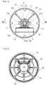
Fig. 5 is a plan view of the hybrid street light; -
Fig. 6 is a bottom view of the hybrid street light; -
Fig. 7 is a perspective view of the hybrid street light; -
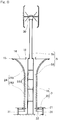
Fig. 8 is a cross-sectional view taken along a line VIII to VIII inFig. 5 ; -
Fig. 9 is a perspective view showing a lighting device and the like of the hybrid street light; and -
Fig. 10 is a block diagram schematically showing a control system of the hybrid street light. - A hybrid street light according to one embodiment of the present invention will be described with reference to
Fig. 1 to Fig. 10 . As shown inFig. 1 , the hybrid street light includes a power generation devicemain unit 1, alighting device 2, aseat 3, acontroller 26, astorage battery 27, and aninverter 28. The powergeneration device body 1 includes a wind turbinepower generation device 6 and a solar photovoltaicpower generation device 7 which are provided on asupport column 5. Thesupport column 5 includes: a support columnlower portion 5a installed on the ground and standing so as to extend upward; and a support columnupper portion 5b linearly connected to the upper end of the support columnlower portion 5a. An upper end portion of the support columnlower portion 5a is located at substantially the same position in the vertical direction as that of thelighting device 2. Each of the support columnlower portion 5a and the support columnupper portion 5b is a columnar hollow cylindrical member. Thus, cables (not shown) and the like of the powergeneration device body 1 and thelighting device 2 can be led into the support columnlower portion 5a and the support columnupper portion 5b. - As shown in
Fig. 8 , the support columnlower portion 5a has a larger diameter than that of the support columnupper portion 5b, and is provided concentrically with the support columnupper portion 5b. Inside the support columnlower portion 5a, a plurality of partition walls 5aa are provided so as to be arrayed at appropriate intervals in the longitudinal direction that matches the vertical direction. Each partition wall 5aa is formed in, for example, a shape of an inner-diametric flange that protrudes in the radially inward direction from the inner circumferential surface of the support columnlower portion 5a, thereby partitioning the inside space of the support columnlower portion 5a. The partition walls 5aa have respective through holes (not shown) formed so as to allow the cables and the like to pass therethrough, for example. - A predetermined partition wall 5aa in the support column
lower portion 5a supports thecontroller 26, thestorage battery 27, and theinverter 28 which are described later. Theinverter 28 may be omitted. In a case where, for example, a plurality of thestorage batteries 27 are provided, thesestorage batteries 27 are supported by the partition walls 5aa that are different from one another. Therefore, thecontrollers 26, thestorage batteries 27, and theinverters 28 in the support columnlower portion 5a are disposed in respective spaces separated from one another by the partition walls 5aa that are different from one another. As shown inFig. 1 andFig. 3 , a plurality (in this example, two) of opening portions 5ab are formed in the front surface of the support columnlower portion 5a, anddoors 4 are respectively provided so as to be capable of closing these opening portions 5ab. Eachdoor 4 is disposed below thelighting device 2, and is formed so as to be openable and closable. If eachdoor 4 is brought into an opened state, thecontroller 26, thestorage battery 27, and theinverter 28 can be accessed and operated, and can be inserted and removed through the opening portions 5ab. As shown inFig. 1 , the support columnupper portion 5b is provided with the wind turbinepower generation device 6 of a vertical-axis type and the solar photovoltaicpower generation device 7. The wind turbinepower generation device 6 is installed above the solar photovoltaicpower generation device 7. - The wind turbine
power generation device 6 includes aturbine rotor 8, and agenerator 9 which is driven by theturbine rotor 8. Theturbine rotor 8 includes asupport 10 and a plurality ofblades 11. Thesupport 10 is supported at an upper end portion of thesupport column 5 via abearing 60 so as to be rotatable about a vertical axis. Thesupport 10 is a member supporting the plurality (in this example, two) ofblades 11, and is formed in an arm shape so as to extend in the radially outward direction from an upper portion of thesupport column 5. - One of the
blades 11 is connected to one end of thesupport 10, and the other one of theblades 11 is connected to the other end of thesupport 10. A plurality (in this example, four) ofreinforcement members 29 are provided so as to connect thesupport 10 and theblades 11. Eachreinforcement member 29 diagonally extends so as to reach a portion near the upper or lower end of theblades 11 as thereinforcement member 29 extends in the radially outward direction from portions near the center of thesupport 10. The twoblades support column 5 being the center. - Each
blade 11 extends in the vertical direction, and is configured to be rotated about an axis L1 of thesupport column 5 by receiving wind from various directions. Theblade 11 includes: astraight portion 11a extending straight in the vertical direction; andblade tip portions straight portion 11a. Thestraight portion 11a and eachblade tip portion 11b are formed from the same material so as to be integrated with each other. It is noted that the following configuration may be employed: three ormore supports 10 each formed in an arm shape extend radially in the radially outward direction from the upper portion of thesupport column 5, and theblades 11 are respectively provided to thesupports 10. - Each
blade tip portion 11b is in the form of a so-called winglet, by which a wing tip vortex generated from the corresponding blade tip is reduced. Theblade tip portion 11b has a cross section, which is obtained by cutting theblade tip portion 11b along a plane including the axis L1, having a shape inclined so as to progressively approach thesupport column 5 side from the proximal end thereof toward the distal end thereof. The upper and lowerblade tip portions straight portion 11a. - The
generator 9 is accommodated, together with thebearing 60, inside ahousing 30 attached to the upper end portion of thesupport column 5, and is driven by rotation of theblades 11 to generate electric power. A stationary ring which is an inner ring of the bearing is attached to thehousing 30, and a rotating ring which is an outer ring of thebearing 60 is connected to thesupport 10. When theblades 11 are rotated, a rotor of thegenerator 9 is rotated, together with the rotating ring, inside thehousing 30, thereby generating power. As thegenerator 9, an induction generator or a synchronous generator may be used, for example. - The solar photovoltaic
power generation device 7 includes: asolar panel 12 which performs photoelectric conversion by receiving sunlight; and amount 13 shown inFig. 2 supporting thesolar panel 12. Themount 13 is attached to a portion, of the upper portion of thesupport column 5, that is located slightly below theturbine rotor 8. Themount 13 includes acylindrical member 13a, abracket 13b, a reinforcement member 13c, and apanel support portion 13d. Thecylindrical member 13a is fitted and fixed to the outer circumference of the support columnupper portion 5b. Thecylindrical member 13a includes: two division structures which can be separated from each other so as to each have a half-cylindrical shape; and a plurality of bolts and nuts by means of which these division structures are coupled with each other and fixed to the support columnupper portion 5b. - As clearly seen from
Fig. 7 , thebracket 13b is T-shaped as viewed from above, and a base portion of a leg thereof is fixed so as to extend in the radially outward direction from one of the division structures of thecylindrical member 13a. The reinforcement member 13c which is a single member is attached to a portion ranging from a lower part of the one of the division structures to the distal ends of thebracket 13b. Thepanel support portion 13d has an angle adjustment mechanism, which is not shown, capable of adjusting the angle of the tilt of thepanel support portion 13d and thesolar panel 12 relative to the horizontal direction. Thepanel support portion 13d can be fixed at an arbitrary angle by the angle adjustment mechanism. This angle is determined, as appropriate, in accordance with the irradiation angle of sunlight. It is noted that also the angle, about the axis L1, of thesolar panel 12 can be adjusted by temporarily loosening the bolts and nuts of thecylindrical member 13a, turning the two division structures around the axis L1 of the support columnupper portion 5b, and fastening the bolts and nuts at an arbitrary angle about the axis L1. Thesolar panel 12 may be composed of, for example, polycrystalline silicon cells. However, the element for thesolar panel 12 is not limited to the polycrystalline silicon cells. - As shown in
Fig. 5 , thelighting device 2 includes: an annular sheet-like panel 14 annularly disposed around the outer circumference of thesupport column 5; and an annularlight source 15 supported by thepanel 14. Thepanel 14 is not shown inFig. 7 . Specifically, as shown inFig. 8 , an outer-diameter-side portion of the lower surface of thepanel 14 is supported by the upper ends of a frame 16 (described later) of theseat 3. Aflange 17 is fixed to a lower end portion, on the outer circumference, of the support columnupper portion 5b via a plurality ofbrackets 41 shown inFig. 4 . Anannular support member 18 inFig. 5 is fixed to the lower surface of the flange 17 (Fig. 4 ) so as to support an inner-diameter-side portion of thepanel 14. As described above, thelighting device 2 is positioned above thedoors 4, and thus does not hinder opening and closing of thedoors 4. - The
annular support member 18 is provided with a plurality (in this example, four) ofconnection members 19 radially extending from theannular support member 18 to the upper ends of theframe 16. Thoseconnection members 19 are arranged at predetermined intervals in the circumferential direction. As shown inFig. 5 andFig. 8 , thepanel 14 is annularly provided around the outer circumference of thesupport column 5 via theframe 16, theannular support member 18, and the plurality ofconnection members 19. The annularly providedpanel 14 serves also as a protection against rain for people sitting on theseat 3. Thepanel 14 is made from: a resin material or a glass sheet having light-transmitting property (transparency, or optical transparency with diffusibility) and weather resistance; or a metal or the like. As shown inFig. 9 , for example, a plurality of leaf patterns k are drawn on thepanel 14. The leaf patterns k themselves are not optically transparent. Thus, for example, sunlight having filtered through portions, between the plurality of leaf patterns, of thepanel 14 having optical transparency can be incident in the daytime. In a case where thepanel 14 is made from a metal, sunlight having filtered through foliage can be reproduced if thepanel 14 is punched so as to have shapes of leaves by means of a press or the like. - As shown in
Fig. 5 , the annularlight source 15 includes an annular and opticallytransparent tube 15b, and a plurality of light-emitting diodes (LEDs) 15a accommodated in thetube 15b. ThoseLEDs 15a are arranged in thetube 15b at intervals in the circumferential direction. In other words, the plurality ofLEDs 15a are circumferentially arranged around the outer circumference of thesupport column 5 at intervals in the circumferential direction. Among the plurality of circumferentially arrangedLEDs 15a, someLEDs 15a are arranged so as to emit light upward, and theother LEDs 15a are arranged so as to emit light downward. - The some
LEDs 15a for emitting light upward irradiate particularly the solar photovoltaicpower generation device 7 and the wind turbinepower generation device 6 over the entire circumferences, i.e., 360 degrees. Therefore, the position of the hybrid street light is easily recognized at night. Owing to theother LEDs 15a for emitting light downward, the effect of facilitating use by people who sit on theseat 3 is further improved. - As shown in
Fig. 8 , theseat 3 includes: aseat portion 20 provided at a lower part of the hybrid street light; and theframe 16. Theseat portion 20 and theframe 16 are provided so as to be integrated with each other by means of, for example, bolts. Theseat 3 and thelighting device 2 are formed integrally with each other, but are formed separately from thesupport column 5. An integrally structuredcomponent 32 including thelighting device 2 and theseat 3 is composed of a plurality of division structures arranged in the circumferential direction, e.g., twodivision structures component 32 in a plane including the axis L1. Thosedivision structures support column 5 via theflange 17, theannular support member 18, and the like. The twodivision structures component 32 as described above, and thus are configured to be able to be attached to thesupport column 5 after thesupport column 5 is installed. - The
frame 16 hasleg portions 31,annular base portions Fig. 6 ,radial connection portions 23,column portions 24 inFig. 7 , andconnection portions 25. These portions are integrally connected to each other by means of, for example, bolts. The plurality ofannular base portions Fig. 6 and having dimensions in the radial direction that are different from each other, are provided around the outer circumference of the support columnlower portion 5a. Thoseannular base portions support column 5. Theradial connection portions 23 integrally connect theseannular base portions leg portions 31 are fixed to the lower surface of theannular base portion 21, which is one annular base portion of theannular base portions leg portions 31 are installed on the ground. The plurality ofcolumn portions 24 are provided to themultiple leg portions 31 via attachment members so as to stand. Thesecolumn portions 24 are arranged at appropriate intervals in the circumferential direction, and serve also as supports for thesupport column 5. - As shown in
Fig. 4 , eachcolumn portion 24 includes: alinear portion 24a extending from the proximal end side so as to be parallel to the support columnlower portion 5a and disposed around an outer circumferential surface of the support columnlower portion 5a so as to be spaced from the outer circumferential surface; and acurved portion 24b curved so as to be progressively apart from thesupport column 5 from an end of thelinear portion 24a toward the upper end. Theconnection portions 25 connect thecolumn portions 24 to each other that are adjacent to each other in the circumferential direction. The outer-diameter-side portion of the lower surface of thepanel 14 inFig. 8 is connected to the tip of thecurved portion 24b of eachcolumn portion 24. Eachcolumn portion 24 of theframe 16 is connected to thesupport column 5 via thepanel 14, theannular support member 18, and the flange 17 (Fig. 4 ), whereby the stiffness of the entire hybrid street light can be improved. - The
seat portion 20 having a shape of a circular sheet is provided on upper portions of the plurality ofannular base portions seat portion 20 has a shape of a circular sheet such that the upper surface thereof serves as a seat surface, and theseat portion 20 is provided around the outer circumference of thesupport column 5 concentrically with thesupport column 5. Theseat portion 20 is configured such that a plurality of persons can sit thereon. Accordingly, use of the space below thelighting device 2 by a plurality of persons can be facilitated. - As shown in
Fig. 1 , thecontroller 26 which is a control device, thestorage battery 27, and theinverter 28 are provided inside thesupport column 5, specifically, inside the support columnlower portion 5a. As shown inFig. 10 , thecontroller 26 performs control so as to power thelighting device 2 by means of either or both of the wind turbinepower generation device 6 and the solar photovoltaicpower generation device 7. Thecontroller 26 includes, for example, a central control unit and a storage unit which are not shown. - The
solar panel 12 and thegenerator 9 of the wind turbinepower generation device 6 are electrically connected to thecontroller 26. Electric power generated by thesolar panel 12 and thegenerator 9 is stored in thestorage battery 27 through thecontroller 26. Thecontroller 26 causes theinverter 28 to convert DC power stored in thestorage battery 27 into AC power, thereby supplying the AC power to thelighting device 2. Accordingly, each LED 15 (Fig. 5 ) is turned on. A timer switch and the like which are not shown are connected to thecontroller 26. Thecontroller 26 can switch between ON and OFF of each LED 15 (Fig. 5 ) in accordance with a set time determined by the timer switch. - According to the hybrid street light described above, the
lighting device 2 installed on thecolumn 5 inFig. 7 is powered by means of either or both of the wind turbinepower generation device 6 and the solar photovoltaicpower generation device 7. In the daytime during which sunlight is incident, electric power can be generated by the solar photovoltaicpower generation device 7. The wind turbinepower generation device 6 can generate electric power by day and night as long as the wind turbinepower generation device 6 receives wind strong enough to rotate theblades 11. Since the wind turbinepower generation device 6 is of a vertical-axis type, control regarding the wind direction is not needed, whereby the control system can be made simpler than that of a horizontal-axis type. - The vertical-axis wind turbine
power generation device 6 can generate power by receiving wind even if being relatively small-sized, and thus can be preferably installed in, for example, an urban district, a park, a promenade, or an area within the site of a factory. Therefore, the versatility of the hybrid street light can be improved. Theseat 3 is permanently provided to thesupport column 5 of the hybrid street light, and thus people can sit on theseat portion 20 by day and night so that it is possible to facilitate use such as taking breaks, chatting with each other, eating and drinking, and placing their belongings on theseat portion 20. Therefore, an effect of facilitating use, by people, of the space under illumination is obtained so that the space can be efficiently used. - The wind turbine
power generation device 6 is provided at a portion, of the upper portion of thesupport column 5, that is located above the solar photovoltaicpower generation device 7. Therefore, the wind turbinepower generation device 6 more easily receives wind, whereby the efficiency of power generation by the wind turbinepower generation device 6 can be improved. - The integrally structured
component 32 including thelighting device 2 and theseat 3 is detachably attached to thesupport column 5 in a state where the twodivision structures lighting device 2 and theseat 3 are installed, thelighting device 2 and theseat 3 can be attached to thesupport column 5 in accordance with, for example, the budget of a user. Since thelighting device 2 and theseat 3 are integrated with each other, operations of attachment and detachment thereof are easy. In addition, the form or the like of thelighting device 2 or theseat 3 can be easily changed in accordance with the preferences of the user who installs the hybrid street light. - Although the embodiment has been described above with reference to the accompanying drawings, those skilled in the art will readily conceive numerous changes and modifications within the framework of obviousness upon the reading of the specification herein presented of the present invention. Accordingly, such changes and modifications are, unless they depart from the scope of the present invention as delivered from the claims annexed hereto, to be construed as included therein.
-
- 1 ····
- Power generation device main unit
- 2 ····
- Lighting device
- 3 ····
- Seat
- 4 ····
- Door
- 5 ····
- Support column
- 5ab ····
- Opening portion
- 6 ····
- Wind turbine power generation device
- 7 ····
- Solar photovoltaic power generation device
- 8 ····
- Turbine rotor
- 15 ····
- Light-emitting diode (LED)
- 26 ····
- Controller
- 27 ····
- Storage battery
- 30 ····
- Housing
- 60 ····
- Bearing
Claims (9)
- A hybrid street light comprising:a support column;a power generation device main unit including, at an upper portion of the support column, a wind turbine power generation device of a vertical-axis type and a solar photovoltaic power generation device;a lighting device installed on the support column and configured to be powered by means of either or both of the wind turbine power generation device and the solar photovoltaic power generation device; anda seat attached to the support column.
- The hybrid street light as claimed in claim 1, wherein the wind turbine power generation device is provided at a portion, of the upper portion of the support column, that is located above the solar photovoltaic power generation device.
- The hybrid street light as claimed in claim 1 or 2, wherein the lighting device includes a plurality of light-emitting diodes circumferentially arranged around the outer circumference of the support column.
- The hybrid street light as claimed in any one of claims 1 to 3, wherein the seat is annularly provided around the outer circumference of the support column.
- The hybrid street light as claimed in any one of claims 1 to 4, wherein the lighting device and the seat are detachably attached to the support column in a state of being combined with each other.
- The hybrid street light as claimed in any one of claims 1 to 5, wherein the support column accommodates therein: a storage battery configured to store electric power generated by the wind turbine power generation device and the solar photovoltaic power generation device and to supply the electric power to the lighting device; and a controller configured to control the storage and the supply of the electric power.
- The hybrid street light as claimed in claim 6, wherein the support column has: an opening portion through which the storage battery and the controller are inserted and removed; and a door configured to close and open the opening portion.
- The hybrid street light as claimed in claim 7, wherein the door is disposed below the lighting device.
- The hybrid street light as claimed in any one of claims 1 to 8, wherein a housing is attached to an upper end portion of the support column, the housing being configured to accommodate: a bearing rotatably supporting a turbine rotor of the wind turbine power generation device; and a generator configured to be driven by rotation of the turbine rotor to generate electric power.
Applications Claiming Priority (2)
| Application Number | Priority Date | Filing Date | Title |
|---|---|---|---|
| JP2016081645A JP2017190751A (en) | 2016-04-15 | 2016-04-15 | Hybrid street light |
| PCT/JP2017/014931 WO2017179607A1 (en) | 2016-04-15 | 2017-04-12 | Hybrid street light |
Publications (2)
| Publication Number | Publication Date |
|---|---|
| EP3505810A1 true EP3505810A1 (en) | 2019-07-03 |
| EP3505810A4 EP3505810A4 (en) | 2020-05-06 |
Family
ID=60042177
Family Applications (1)
| Application Number | Title | Priority Date | Filing Date |
|---|---|---|---|
| EP17782420.8A Withdrawn EP3505810A4 (en) | 2016-04-15 | 2017-04-12 | Hybrid street light |
Country Status (6)
| Country | Link |
|---|---|
| US (1) | US20190041015A1 (en) |
| EP (1) | EP3505810A4 (en) |
| JP (1) | JP2017190751A (en) |
| KR (1) | KR20180132086A (en) |
| CN (1) | CN109073178A (en) |
| WO (1) | WO2017179607A1 (en) |
Cited By (1)
| Publication number | Priority date | Publication date | Assignee | Title |
|---|---|---|---|---|
| CN113623599A (en) * | 2021-07-12 | 2021-11-09 | 安徽省通信产业服务有限公司 | Wisdom garden illumination monitoring device |
Families Citing this family (14)
| Publication number | Priority date | Publication date | Assignee | Title |
|---|---|---|---|---|
| FR3078372B1 (en) * | 2018-02-26 | 2020-12-11 | Steinke Gallo Sabrina | LIFI AND MULTI-SOURCE OPTIMIZATION FOR A WIND TURBINE OR PANEL TOTEM |
| CN108626669B (en) * | 2018-05-15 | 2019-05-07 | 浙江新欣景观建设工程有限公司 | A kind of Intelligent road equipment |
| CN108613085A (en) * | 2018-05-16 | 2018-10-02 | 温岭市兴庆机械设备有限公司 | A kind of intelligent solar road lamp system |
| CN108799988A (en) * | 2018-05-16 | 2018-11-13 | 温岭市兴庆机械设备有限公司 | A kind of hommization intelligent solar road lamp system |
| JP6997676B2 (en) * | 2018-05-29 | 2022-01-17 | Ntn株式会社 | Vertical axis wind turbine and wind power generation equipment and lighting equipment equipped with it |
| JP7353596B2 (en) * | 2019-04-15 | 2023-10-02 | Ntn株式会社 | wind power generator |
| PL431158A1 (en) * | 2019-09-16 | 2021-03-22 | Enverti Spółka Z Ograniczoną Odpowiedzialnością | Wind turbine rotor with vertical rotation axis |
| JP7573374B2 (en) | 2020-03-27 | 2024-10-25 | Ntn株式会社 | Vertical Axis Wind Turbine |
| CN111550722A (en) * | 2020-05-13 | 2020-08-18 | 吴巨才 | Solar street lamp is used in sponge city construction |
| CN112490911B (en) * | 2020-12-14 | 2022-07-26 | 孔祥富 | Energy-saving heat dissipation type high-voltage board |
| CA3128701A1 (en) * | 2021-08-20 | 2023-02-20 | Solidel Canada Inc. | High power vertical modular structure apparatus supporting solar panels |
| CN114704796B (en) * | 2022-04-21 | 2022-12-06 | 江苏飞腾光电科技有限公司 | Wisdom city is with high-power wide angle illumination LED street lamp |
| CN117189482A (en) * | 2023-09-12 | 2023-12-08 | 湖南凌特科技有限公司 | A wind-solar powered aviation obstruction light |
| KR102640918B1 (en) * | 2023-11-16 | 2024-02-27 | 주식회사 에스에스라이트 | ICT-based fully independent hybrid streetlight system |
Family Cites Families (21)
| Publication number | Priority date | Publication date | Assignee | Title |
|---|---|---|---|---|
| JP3038364U (en) * | 1996-12-03 | 1997-06-20 | 英太郎 田中 | Wind power generator |
| DE20000688U1 (en) * | 2000-01-17 | 2000-04-13 | Bock, Manfred, Dipl.-Ing., 30455 Hannover | Solar lamp post |
| JP2002025314A (en) * | 2000-07-13 | 2002-01-25 | Yoshimoto Pole Co Ltd | Lighting column with power generation function |
| JP3638899B2 (en) * | 2001-11-01 | 2005-04-13 | 星和電機株式会社 | Lighting equipment |
| JP3103301U (en) * | 2004-02-10 | 2004-08-05 | 日本フネン株式会社 | Lighting tower equipment and mountings for lighting towers |
| US7731383B2 (en) * | 2007-02-02 | 2010-06-08 | Inovus Solar, Inc. | Solar-powered light pole and LED light fixture |
| CA2659533C (en) * | 2008-03-27 | 2013-07-16 | Abl Ip Holding, Llc | Back-up lighting system |
| US20090273922A1 (en) * | 2008-05-05 | 2009-11-05 | Tseng Fong Ho | Street light utilizing combination low-pressure sodium and metal halide light sources |
| US8106593B2 (en) * | 2008-10-09 | 2012-01-31 | Nevins Michael Olen | Hybrid lighting device |
| JP2011027054A (en) * | 2009-07-28 | 2011-02-10 | Global Energy Co Ltd | Blade of wind turbine |
| JP2011122508A (en) * | 2009-12-10 | 2011-06-23 | Kayseven Co Ltd | Power generator |
| WO2013024515A1 (en) * | 2011-08-12 | 2013-02-21 | 大島工業株式会社 | Hybrid generation-type streetlamp |
| KR101213920B1 (en) * | 2011-08-13 | 2012-12-18 | 오대국 | Multi-faceted solar modules and flexible solar modules |
| KR20130066418A (en) * | 2011-12-12 | 2013-06-20 | (주)한국하이텍 | Bench street light with mood led lamp and height control part |
| WO2014036356A2 (en) * | 2012-08-31 | 2014-03-06 | Wing Power Energy, Inc. | Solar petrofit pole |
| CN203249126U (en) * | 2013-03-29 | 2013-10-23 | 河海大学 | A New Type of Urban Leisure Street Light |
| TWM462425U (en) * | 2013-05-31 | 2013-09-21 | 光碁科技股份有限公司 | Self-contained power station |
| CN103335272A (en) * | 2013-07-18 | 2013-10-02 | 青岛易特优电子有限公司 | Wind-light complementary illumination device |
| CN104712987A (en) * | 2013-12-12 | 2015-06-17 | 西安麟字半导体照明有限公司 | Landscape lamp with pedestrian resting function |
| FR3022331B1 (en) * | 2014-06-12 | 2019-06-21 | Tmc Innovation | ANNULAR CAGE FOR LIGHTING MAT, CLOSURE ELEMENT OF SAID CAGE AND MAT INTEGRATING SUCH A CAGE |
| CN204534419U (en) * | 2015-05-03 | 2015-08-05 | 刘恒 | A kind of solar street light with rumble seat |
-
2016
- 2016-04-15 JP JP2016081645A patent/JP2017190751A/en active Pending
-
2017
- 2017-04-12 KR KR1020187030766A patent/KR20180132086A/en not_active Withdrawn
- 2017-04-12 EP EP17782420.8A patent/EP3505810A4/en not_active Withdrawn
- 2017-04-12 WO PCT/JP2017/014931 patent/WO2017179607A1/en not_active Ceased
- 2017-04-12 CN CN201780023290.3A patent/CN109073178A/en active Pending
-
2018
- 2018-10-10 US US16/156,390 patent/US20190041015A1/en not_active Abandoned
Cited By (1)
| Publication number | Priority date | Publication date | Assignee | Title |
|---|---|---|---|---|
| CN113623599A (en) * | 2021-07-12 | 2021-11-09 | 安徽省通信产业服务有限公司 | Wisdom garden illumination monitoring device |
Also Published As
| Publication number | Publication date |
|---|---|
| CN109073178A (en) | 2018-12-21 |
| US20190041015A1 (en) | 2019-02-07 |
| EP3505810A4 (en) | 2020-05-06 |
| JP2017190751A (en) | 2017-10-19 |
| WO2017179607A1 (en) | 2017-10-19 |
| KR20180132086A (en) | 2018-12-11 |
Similar Documents
| Publication | Publication Date | Title |
|---|---|---|
| US20190041015A1 (en) | Hybrid street light | |
| US7731383B2 (en) | Solar-powered light pole and LED light fixture | |
| US8282236B2 (en) | Wind powered device | |
| US20100220467A1 (en) | Wind and solar-powered light apparatus | |
| US20040228118A1 (en) | Illuminated solar umbrella | |
| US20130234605A1 (en) | Hybrid Outdoor Streetlamp Assembly | |
| KR101781168B1 (en) | Sunflower structure based on multiple generation | |
| JP2007303459A (en) | Generating set for consumer | |
| CN110686205A (en) | Engineering street lamp capable of automatically changing illumination intensity | |
| WO2018088681A1 (en) | Hybrid-powered street light | |
| KR101390515B1 (en) | Solar streetlamp | |
| KR101222895B1 (en) | A solarcell security light | |
| KR101362447B1 (en) | Solar powered street lights having a wind power generator | |
| KR102199550B1 (en) | Solar garden light with built-in speaker | |
| KR101166519B1 (en) | Solar tree and artificial structure comprising the same | |
| KR200468885Y1 (en) | Hybrid streetlight | |
| JP5220052B2 (en) | Guidance sign | |
| KR20220135791A (en) | Hybrid street light | |
| CN109495056A (en) | A kind of angle adjustable integral type power generator based on solar energy and wind energy | |
| RU2530959C1 (en) | Solar photovoltaic power plant | |
| CN110645521A (en) | Energy-saving power supply device for new energy street lamp | |
| CN215052358U (en) | Indicating device that changes its course that town road construction was used | |
| CN222103445U (en) | A solar lamp with vertically mounted solar panels | |
| KR102622682B1 (en) | solar power generation device | |
| JP2015059361A (en) | Eaves structure |
Legal Events
| Date | Code | Title | Description |
|---|---|---|---|
| STAA | Information on the status of an ep patent application or granted ep patent |
Free format text: STATUS: THE INTERNATIONAL PUBLICATION HAS BEEN MADE |
|
| PUAI | Public reference made under article 153(3) epc to a published international application that has entered the european phase |
Free format text: ORIGINAL CODE: 0009012 |
|
| STAA | Information on the status of an ep patent application or granted ep patent |
Free format text: STATUS: REQUEST FOR EXAMINATION WAS MADE |
|
| 17P | Request for examination filed |
Effective date: 20181102 |
|
| AK | Designated contracting states |
Kind code of ref document: A1 Designated state(s): AL AT BE BG CH CY CZ DE DK EE ES FI FR GB GR HR HU IE IS IT LI LT LU LV MC MK MT NL NO PL PT RO RS SE SI SK SM TR |
|
| AX | Request for extension of the european patent |
Extension state: BA ME |
|
| DAV | Request for validation of the european patent (deleted) | ||
| DAX | Request for extension of the european patent (deleted) | ||
| A4 | Supplementary search report drawn up and despatched |
Effective date: 20200408 |
|
| RIC1 | Information provided on ipc code assigned before grant |
Ipc: F21S 8/08 20060101AFI20200402BHEP Ipc: F03D 3/00 20060101ALI20200402BHEP Ipc: F21S 9/03 20060101ALI20200402BHEP Ipc: F21S 9/02 20060101ALI20200402BHEP Ipc: F21Y 103/33 20160101ALN20200402BHEP Ipc: F21Y 115/10 20160101ALN20200402BHEP Ipc: F03D 9/46 20160101ALI20200402BHEP Ipc: F03D 3/06 20060101ALI20200402BHEP |
|
| STAA | Information on the status of an ep patent application or granted ep patent |
Free format text: STATUS: THE APPLICATION HAS BEEN WITHDRAWN |
|
| 18W | Application withdrawn |
Effective date: 20211028 |