EP3505424B1 - Kart - Google Patents
Kart Download PDFInfo
- Publication number
- EP3505424B1 EP3505424B1 EP18213384.3A EP18213384A EP3505424B1 EP 3505424 B1 EP3505424 B1 EP 3505424B1 EP 18213384 A EP18213384 A EP 18213384A EP 3505424 B1 EP3505424 B1 EP 3505424B1
- Authority
- EP
- European Patent Office
- Prior art keywords
- frame
- protective element
- rubber
- protective
- kart
- Prior art date
- Legal status (The legal status is an assumption and is not a legal conclusion. Google has not performed a legal analysis and makes no representation as to the accuracy of the status listed.)
- Active
Links
Images


Classifications
-
- B—PERFORMING OPERATIONS; TRANSPORTING
- B60—VEHICLES IN GENERAL
- B60R—VEHICLES, VEHICLE FITTINGS, OR VEHICLE PARTS, NOT OTHERWISE PROVIDED FOR
- B60R19/00—Wheel guards; Radiator guards, e.g. grilles; Obstruction removers; Fittings damping bouncing force in collisions
- B60R19/02—Bumpers, i.e. impact receiving or absorbing members for protecting vehicles or fending off blows from other vehicles or objects
- B60R19/42—Bumpers, i.e. impact receiving or absorbing members for protecting vehicles or fending off blows from other vehicles or objects extending primarily along the sides of, or completely encircling, a vehicle
-
- B—PERFORMING OPERATIONS; TRANSPORTING
- B60—VEHICLES IN GENERAL
- B60R—VEHICLES, VEHICLE FITTINGS, OR VEHICLE PARTS, NOT OTHERWISE PROVIDED FOR
- B60R19/00—Wheel guards; Radiator guards, e.g. grilles; Obstruction removers; Fittings damping bouncing force in collisions
- B60R19/02—Bumpers, i.e. impact receiving or absorbing members for protecting vehicles or fending off blows from other vehicles or objects
- B60R19/24—Arrangements for mounting bumpers on vehicles
- B60R19/26—Arrangements for mounting bumpers on vehicles comprising yieldable mounting means
- B60R19/30—Elastomeric material
-
- B—PERFORMING OPERATIONS; TRANSPORTING
- B60—VEHICLES IN GENERAL
- B60R—VEHICLES, VEHICLE FITTINGS, OR VEHICLE PARTS, NOT OTHERWISE PROVIDED FOR
- B60R19/00—Wheel guards; Radiator guards, e.g. grilles; Obstruction removers; Fittings damping bouncing force in collisions
- B60R19/02—Bumpers, i.e. impact receiving or absorbing members for protecting vehicles or fending off blows from other vehicles or objects
- B60R19/24—Arrangements for mounting bumpers on vehicles
- B60R19/38—Arrangements for mounting bumpers on vehicles adjustably or movably mounted, e.g. horizontally displaceable for securing a space between parked vehicles
-
- B—PERFORMING OPERATIONS; TRANSPORTING
- B62—LAND VEHICLES FOR TRAVELLING OTHERWISE THAN ON RAILS
- B62D—MOTOR VEHICLES; TRAILERS
- B62D21/00—Understructures, i.e. chassis frame on which a vehicle body may be mounted
- B62D21/18—Understructures, i.e. chassis frame on which a vehicle body may be mounted characterised by the vehicle type and not provided for in groups B62D21/02 - B62D21/17
- B62D21/183—Understructures, i.e. chassis frame on which a vehicle body may be mounted characterised by the vehicle type and not provided for in groups B62D21/02 - B62D21/17 specially adapted for sports vehicles, e.g. race, dune buggies, go-karts
-
- B—PERFORMING OPERATIONS; TRANSPORTING
- B60—VEHICLES IN GENERAL
- B60R—VEHICLES, VEHICLE FITTINGS, OR VEHICLE PARTS, NOT OTHERWISE PROVIDED FOR
- B60R19/00—Wheel guards; Radiator guards, e.g. grilles; Obstruction removers; Fittings damping bouncing force in collisions
- B60R19/02—Bumpers, i.e. impact receiving or absorbing members for protecting vehicles or fending off blows from other vehicles or objects
- B60R19/24—Arrangements for mounting bumpers on vehicles
- B60R19/26—Arrangements for mounting bumpers on vehicles comprising yieldable mounting means
- B60R2019/262—Arrangements for mounting bumpers on vehicles comprising yieldable mounting means with means to adjust or regulate the amount of energy to be absorbed
-
- B—PERFORMING OPERATIONS; TRANSPORTING
- B60—VEHICLES IN GENERAL
- B60R—VEHICLES, VEHICLE FITTINGS, OR VEHICLE PARTS, NOT OTHERWISE PROVIDED FOR
- B60R21/00—Arrangements or fittings on vehicles for protecting or preventing injuries to occupants or pedestrians in case of accidents or other traffic risks
- B60R2021/0065—Type of vehicles
- B60R2021/0086—Racing cars
-
- B—PERFORMING OPERATIONS; TRANSPORTING
- B60—VEHICLES IN GENERAL
- B60Y—INDEXING SCHEME RELATING TO ASPECTS CROSS-CUTTING VEHICLE TECHNOLOGY
- B60Y2200/00—Type of vehicle
- B60Y2200/10—Road Vehicles
- B60Y2200/11—Passenger cars; Automobiles
- B60Y2200/114—Racing vehicles, e.g. Formula one, Karts
Definitions
- the invention relates to a kart having a frame, a front and a rear axle and an impact protection surrounding the frame, and having at least one front and one rear protective element and at least one lateral protective element on each frame side of the kart, wherein shock-absorbing rubber-elastic dampers are provided between the frame and the protective elements, wherein the pivot bearings are provided near the rear axle and each comprise a bearing block fixed to the frame and a bearing pedestal pivotally adjustable relative to said bearing block, wherein the lateral protective elements each engage on the associated bearing pedestal.
- Such protective elements i.e. bumpers that fully or partially enclose the front, rear and side of the frame, are used in karts to dampen impact loads on the frame and the driver in the event of a collision and thus protect both the driver and the vehicle from damage caused by impact forces.
- vehicles in particular karts, are usually equipped with bumpers connected to their chassis.
- bumpers and/or shock-absorbing rubber-elastic dampers are deformed elastically or plastically, whereby the kinetic energy of the impact is at least partially absorbed.
- shock-absorbing rubber-elastic dampers are deformed elastically or plastically, whereby the kinetic energy of the impact is at least partially absorbed.
- Such devices are known for example from the US 5 806 901 A and the WO 03/057538 A1 .
- US 5 806 901 A discloses a kart according to the preamble of claim 1 with lateral bumper sections that are pivotally mounted to a frame at pivots.
- the pivot bearings are close to the front axle wherein the bumper is pivotally mounted to the frame itself without a bearing pedestal. Similar is known from the EP 2 204 303 A1 .
- bumpers are particularly necessary for karts under rental, as the vehicles in the rental area are usually not treated gently and are therefore considerably overstressed.
- karts are usually equipped not only with front and rear bumpers attached to the frame, but also on the long sides. It is intended to thus avoid repairs or the replacement of damaged kart components.
- shock-absorbing, rubber-elastic dampers can be provided between the protective element and the frame, consisting for example of deformable rubber elements (EP 2 204 303 A ).
- deformable rubber elements EP 2 204 303 A
- shock absorbers located between the frame and the protective element (EP 2 246 221 A ).
- shock absorbers only transmit forces in the direction of the longitudinal axis of the vehicle and can therefore only absorb impact forces resulting from a frontal impact, which is also a disadvantage of such solutions. Transverse components of the impact forces can even damage such shock absorbers.
- the invention is therefore based on the object of creating a kart of the initially described type whose side impact protection can absorb normal and transverse forces well and is nevertheless held securely on the frame and guided in a defined manner in relation to the frame.
- the invention solves the object set by providing a kart with the features of claim 1. This ensures that the side impact protection transmits impact-related normal and transverse forces into the frame in a well-damped manner, while the pivot bearing ensures that they are always held securely on the frame and guided in a defined manner relative to the frame.
- the protective element In the event of a force acting on a lateral protective element, the protective element is displaced around the pivot bearing axis, a frame vertical axis, against the spring force of rubber-elastic dampers against the frame.
- the protective element is designed in particular in the form of a single-arm lever which can be pivoted freely or damped via the pivot bearing on the frame. Since the pivot bearing is provided near the rear axle, practically in the wheel arch, it is also protected against direct impact loading.
- the lateral protective elements in the central area between the front and rear axle may be bent outwards in the direction of a frame transverse axis, curved outwards or the like, and drawn in close to the frame longitudinal axis from the front and rear axles. In most practical cases, any impact load first acts on the lateral protective element in the area of the greatest distance between the arch and the longitudinal axis of the frame and not in the vicinity of the pivot bearing.
- buffers acting as rubber-elastic dampers are provided between the frame and the lateral protective elements in the central area between the front and rear axle.
- the number and damping performance of the rubber-elastic dampers used in each case must be adapted to the design of the person skilled in the art and the respective purpose of use of the kart.
- the shock-absorbing, rubber-elastic dampers can be buffers in particular, which are attached to one side of the frame and transmit only normal forces and practically no transverse forces, since they are preferably not connected to the assigned protective element or rubber-elastic bearings transmitting normal and transverse forces, which are connected on the one hand to the frame and on the other hand to the assigned protective element.
- the lateral protective elements each attack the front and rear protective elements directly or indirectly via connecting protective elements, wherein the lateral protective element is connected to the assigned rear connecting protective element via the bearing pedestal. This ensures that the wheels and wheel axes are also protected against accidental excessive impact loads.
- each screw connection comprises a nut which is radially secured and held rotationally fixed in a recess of an associated first protective element and a washer which is radially secured in a recess of a second protective element to be connected to the first, with a conical seat for a conical seat screw which engages in the nut.
- the conical seat ensures proper mutual alignment of the protective elements to be screwed together.
- At least one shock-absorbing buffer acting as a rubber-elastic damper is provided.
- a major advantage of these buffers is that they are relatively inexpensive and can be changed quickly.
- At least one rubber-elastic bearing can also be provided. Rubber-elastic bearings can also transmit transverse forces and thus ensure that the impact protection is properly held in position even at a greater distance from the pivot bearing fixed to the frame.
- At least one shock-absorbing buffer acting as a rubber-elastic damper is provided between the frame and the rear protective element.
- the rear protective element be mounted in the longitudinal guides assigned to the frame and that the buffers be guided against the spring force in the direction of the frame longitudinal axis so that they can be displaced relative to the frame. An undefined evasion of the rear protective element in the event of an impact load can thus be avoided.
- the said nipple-shaped buffers to be used have in particular a mounting body from which the buffer body projects freely, which on its side opposite the mounting body forms a stop for a protective element, wherein the buffer body consists of elastic material, in particular rubber or rubber-elastic foam.
- a kart 1 according to the invention comprises a frame 2, a front and a rear axle 3, 4 and an impact protection surrounding the frame 2.
- Frame 2 is a tubular steel frame which supports the other vehicle components.
- vehicle parts that are not relevant to the invention, such as the engine, tank, batteries, seat, fairings, etc., are not shown in the drawing.
- the impact protection has at least one front and one rear and at least one lateral protective element S1, S2, S3, S4 on each side of the kart frame. These protective elements S1, S2, S3, S4 are connected by means of connecting protective elements S5, S6, S7, S8. Between the frame 2 and the protective elements S1, S2, S3, S4, S5, S6, shock-absorbing rubber-elastic dampers are provided.
- the shock-absorbing rubber-elastic dampers are, in particular, buffers 5, which transmit only normal forces and practically no transverse forces, and the rubber-elastic bearings 6, which transmit normal and transverse forces.
- the lateral protective elements S3, S4 are each mounted on a pivot bearing 7 fixed to the frame so that they can be pivoted about a frame vertical axis 8.
- the pivot bearings 7 of the two frame sides are provided near the rear axle between a lateral frame attachment 9 and the rear axle 4 and are attached to the frame attachment 9.
- the pivot bearings 7 each comprise a bearing block 10 fixed to the frame and a bearing pedestal 11 pivotally adjustable in relation to this bearing pedestal, wherein the lateral protective elements S3, S4 and in the embodiment example also the connecting protective elements S7, S8 each engage on the assigned bearing pedestal 11.
- the pivot bearing is positioned in the end area of the lateral protective element (S3, S4) as shown in the drawing. S3/S4 could also be shorter than shown in the drawing.
- the lateral protective elements S3, S4 are bent outwards in the central area between front and rear axle 3, 4 in the direction of a frame transverse axis 12, i.e. convex, and in the near area between front and rear axle 3, 4 they are pulled in towards the frame longitudinal axis 13. This ensures that the pivot bearing 7 cannot be hit directly in the event of a side impact and that the impact forces can be absorbed by buffers 5 acting as rubber-elastic dampers between the frame 2 and the lateral protective elements in the central area between the front and rear axle.
- the buffers 5 engage with the protective elements S3, S4 in the central area between the front and rear axle or where the protective elements S3, S4 protrude the farthest to the outside.
- the pivot bearing 7 is arranged in front of the rear tire and does not protrude beyond it towards the outside.
- the lateral protective elements S3, S4 each indirectly engage the front and rear protective elements S1, S2 via the connecting protective elements S5, S6, S7, S8, wherein the lateral protective element S3, S4 is connected to the assigned connecting protective element S7, S8 via the bearing pedestal 11.
- shock-absorbing buffers 5 acting as rubber-elastic dampers are provided and one rubber-elastic bearing each is provided between the frame 2 and the front connecting protective elements S5, S6.
- Two shock-absorbing buffers 5 acting as rubber-elastic dampers are also provided between frame 2 and the rear protective element S2.
- the rear protective element S2 is mounted in the longitudinal guides 14 assigned to the frame and guided against the spring force of the buffers 5 in the direction of the frame longitudinal axis13 in a displaceable manner relative to the frame 2.
- the guides can also permit a defined transverse guidance of the protective element S2, for which purpose the connecting bow between protective element S2 and longitudinal guide 14 can form a transverse guide, which is covered in the drawing ( Fig. 2 ) by a washer of the screw connection of connecting bracket and longitudinal guide 14.
- the bearing thus enables a displacement of approx. 50 mm in the longitudinal direction and approx. 7 mm in the transverse direction.
- the protective elements S1 to S4 and connecting protective elements S5 to S8 are screwed together.
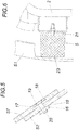
- These screw connections each comprise a nut 16 radially secured in a recess 15 of an associated first protective element and a washer 18 radially secured in a recess 17 of a second protective element to be connected to the first, with a conical seat 19 for a conical seat screw 20 engaging in the nut 16.
- the protective elements can thus be screwed together more easily, as the screw connection can initially be easily set in place even if the protective elements do not fit exactly one above the other and, subsequently, when the screw connection is tightened, automatic alignment takes place as a result of the design features.
- the buffers 5 have a mounting body 21, from which the buffer body 22 freely projects, which on its side opposite the mounting body forms a stop 23 for a protective element, wherein the buffer body 22 consists of elastic material, in particular rubber or rubber-elastic foam.
Landscapes
- Engineering & Computer Science (AREA)
- Mechanical Engineering (AREA)
- Chemical & Material Sciences (AREA)
- Combustion & Propulsion (AREA)
- Transportation (AREA)
- Vibration Dampers (AREA)
- Vehicle Body Suspensions (AREA)
Description
- The invention relates to a kart having a frame, a front and a rear axle and an impact protection surrounding the frame, and having at least one front and one rear protective element and at least one lateral protective element on each frame side of the kart, wherein shock-absorbing rubber-elastic dampers are provided between the frame and the protective elements, wherein the pivot bearings are provided near the rear axle and each comprise a bearing block fixed to the frame and a bearing pedestal pivotally adjustable relative to said bearing block, wherein the lateral protective elements each engage on the associated bearing pedestal.
- Such protective elements, i.e. bumpers that fully or partially enclose the front, rear and side of the frame, are used in karts to dampen impact loads on the frame and the driver in the event of a collision and thus protect both the driver and the vehicle from damage caused by impact forces.
- For this purpose, vehicles, in particular karts, are usually equipped with bumpers connected to their chassis. In the event of an impact, bumpers and/or shock-absorbing rubber-elastic dampers are deformed elastically or plastically, whereby the kinetic energy of the impact is at least partially absorbed. Such devices are known for example from the
US 5 806 901 A and theWO 03/057538 A1 -
US 5 806 901 A discloses a kart according to the preamble ofclaim 1 with lateral bumper sections that are pivotally mounted to a frame at pivots. The pivot bearings are close to the front axle wherein the bumper is pivotally mounted to the frame itself without a bearing pedestal. Similar is known from theEP 2 204 303 A1 - The use of bumpers is particularly necessary for karts under rental, as the vehicles in the rental area are usually not treated gently and are therefore considerably overstressed.
- To ensure that neither the frame or body parts nor, in particular, the driver of a kart are unduly affected in the course of such treatment, karts are usually equipped not only with front and rear bumpers attached to the frame, but also on the long sides. It is intended to thus avoid repairs or the replacement of damaged kart components.
- It is necessary that the impact protection returns elastically to its non-deformed ready position after an impact deforming a protective element. The protective elements must be held securely on the frame and should safely dissipate impulse peaks acting on the kart. For this purpose, shock-absorbing, rubber-elastic dampers can be provided between the protective element and the frame, consisting for example of deformable rubber elements (
EP 2 204 303 A - It is also known that karts are fitted with shock absorbers located between the frame and the protective element (
EP 2 246 221 A - The invention is therefore based on the object of creating a kart of the initially described type whose side impact protection can absorb normal and transverse forces well and is nevertheless held securely on the frame and guided in a defined manner in relation to the frame.
- The invention solves the object set by providing a kart with the features of
claim 1. This ensures that the side impact protection transmits impact-related normal and transverse forces into the frame in a well-damped manner, while the pivot bearing ensures that they are always held securely on the frame and guided in a defined manner relative to the frame. In the event of a force acting on a lateral protective element, the protective element is displaced around the pivot bearing axis, a frame vertical axis, against the spring force of rubber-elastic dampers against the frame. The protective element is designed in particular in the form of a single-arm lever which can be pivoted freely or damped via the pivot bearing on the frame. Since the pivot bearing is provided near the rear axle, practically in the wheel arch, it is also protected against direct impact loading. - In order to ensure that the pivot bearing actually only performs pivoting movements and is protected against excessive impact loading, the lateral protective elements in the central area between the front and rear axle may be bent outwards in the direction of a frame transverse axis, curved outwards or the like, and drawn in close to the frame longitudinal axis from the front and rear axles. In most practical cases, any impact load first acts on the lateral protective element in the area of the greatest distance between the arch and the longitudinal axis of the frame and not in the vicinity of the pivot bearing.
- In order to be able to absorb the impact forces in this area in an advantageous way, it is recommended that buffers acting as rubber-elastic dampers are provided between the frame and the lateral protective elements in the central area between the front and rear axle. The number and damping performance of the rubber-elastic dampers used in each case must be adapted to the design of the person skilled in the art and the respective purpose of use of the kart.
- In this case, the shock-absorbing, rubber-elastic dampers can be buffers in particular, which are attached to one side of the frame and transmit only normal forces and practically no transverse forces, since they are preferably not connected to the assigned protective element or rubber-elastic bearings transmitting normal and transverse forces, which are connected on the one hand to the frame and on the other hand to the assigned protective element.
- The lateral protective elements each attack the front and rear protective elements directly or indirectly via connecting protective elements, wherein the lateral protective element is connected to the assigned rear connecting protective element via the bearing pedestal. This ensures that the wheels and wheel axes are also protected against accidental excessive impact loads.
- The individual protective elements and, optionally, the connecting protective elements are preferably bolted together to improve the maintainability of the kart. Since the protective elements can also be permanently deformed due to impact, or are intentionally to be screwed together under a certain preload, it is advantageous if these screw connections allow a certain amount of play when the screws and nuts are fitted, which is why each screw connection comprises a nut which is radially secured and held rotationally fixed in a recess of an associated first protective element and a washer which is radially secured in a recess of a second protective element to be connected to the first, with a conical seat for a conical seat screw which engages in the nut. The conical seat ensures proper mutual alignment of the protective elements to be screwed together.
- Between the frame and the front protective element, preferably also at least one shock-absorbing buffer acting as a rubber-elastic damper is provided. A major advantage of these buffers is that they are relatively inexpensive and can be changed quickly.
- Between the frame and the front protective element or the connecting protective element, however, at least one rubber-elastic bearing can also be provided. Rubber-elastic bearings can also transmit transverse forces and thus ensure that the impact protection is properly held in position even at a greater distance from the pivot bearing fixed to the frame.
- It is also advantageous if at least one shock-absorbing buffer acting as a rubber-elastic damper is provided between the frame and the rear protective element.
- Since the engine requiring special protection is located in the rear area, it is recommended that the rear protective element be mounted in the longitudinal guides assigned to the frame and that the buffers be guided against the spring force in the direction of the frame longitudinal axis so that they can be displaced relative to the frame. An undefined evasion of the rear protective element in the event of an impact load can thus be avoided.
- The said nipple-shaped buffers to be used have in particular a mounting body from which the buffer body projects freely, which on its side opposite the mounting body forms a stop for a protective element, wherein the buffer body consists of elastic material, in particular rubber or rubber-elastic foam.
- The subject matter of the invention is shown by way of example in the drawings, wherein:
- Fig. 1
- shows a kart according to the invention in oblique view,
- Fig. 2
- shows the top view of the kart,
- Fig. 3
- shows an enlarged section of the kart from
Fig. 2 in section according to line III-III, - Fig. 4
- shows an enlarged section of the kart from
Fig. 2 in section according to line IV-IV, - Fig. 5
- shows an enlarged screw connection of two protective elements in cross-section, and
- Fig. 6
- shows a buffer in cross-section.
- A
kart 1 according to the invention comprises aframe 2, a front and arear axle frame 2.Frame 2 is a tubular steel frame which supports the other vehicle components. For reasons of clarity, vehicle parts that are not relevant to the invention, such as the engine, tank, batteries, seat, fairings, etc., are not shown in the drawing. The impact protection has at least one front and one rear and at least one lateral protective element S1, S2, S3, S4 on each side of the kart frame. These protective elements S1, S2, S3, S4 are connected by means of connecting protective elements S5, S6, S7, S8. Between theframe 2 and the protective elements S1, S2, S3, S4, S5, S6, shock-absorbing rubber-elastic dampers are provided. In the present case, the shock-absorbing rubber-elastic dampers are, in particular,buffers 5, which transmit only normal forces and practically no transverse forces, and the rubber-elastic bearings 6, which transmit normal and transverse forces. - To ensure that the side impact protection can absorb and dampen longitudinal and transverse forces well and still be held securely on the frame and guided in a defined manner in relation to the frame, the lateral protective elements S3, S4 are each mounted on a pivot bearing 7 fixed to the frame so that they can be pivoted about a frame
vertical axis 8. Thepivot bearings 7 of the two frame sides are provided near the rear axle between alateral frame attachment 9 and therear axle 4 and are attached to theframe attachment 9. Thepivot bearings 7 each comprise abearing block 10 fixed to the frame and a bearingpedestal 11 pivotally adjustable in relation to this bearing pedestal, wherein the lateral protective elements S3, S4 and in the embodiment example also the connecting protective elements S7, S8 each engage on the assigned bearingpedestal 11. The pivot bearing is positioned in the end area of the lateral protective element (S3, S4) as shown in the drawing. S3/S4 could also be shorter than shown in the drawing. - The lateral protective elements S3, S4 are bent outwards in the central area between front and
rear axle transverse axis 12, i.e. convex, and in the near area between front andrear axle longitudinal axis 13. This ensures that the pivot bearing 7 cannot be hit directly in the event of a side impact and that the impact forces can be absorbed bybuffers 5 acting as rubber-elastic dampers between theframe 2 and the lateral protective elements in the central area between the front and rear axle. Thebuffers 5 engage with the protective elements S3, S4 in the central area between the front and rear axle or where the protective elements S3, S4 protrude the farthest to the outside. Thepivot bearing 7 is arranged in front of the rear tire and does not protrude beyond it towards the outside. The lateral protective elements S3, S4 each indirectly engage the front and rear protective elements S1, S2 via the connecting protective elements S5, S6, S7, S8, wherein the lateral protective element S3, S4 is connected to the assigned connecting protective element S7, S8 via the bearingpedestal 11. - Between the
frame 2 and the front protective element S1 two shock-absorbingbuffers 5 acting as rubber-elastic dampers are provided and one rubber-elastic bearing each is provided between theframe 2 and the front connecting protective elements S5, S6. - Two shock-absorbing
buffers 5 acting as rubber-elastic dampers are also provided betweenframe 2 and the rear protective element S2. In addition, the rear protective element S2 is mounted in thelongitudinal guides 14 assigned to the frame and guided against the spring force of thebuffers 5 in the direction of the frame longitudinal axis13 in a displaceable manner relative to theframe 2. The guides can also permit a defined transverse guidance of the protective element S2, for which purpose the connecting bow between protective element S2 andlongitudinal guide 14 can form a transverse guide, which is covered in the drawing (Fig. 2 ) by a washer of the screw connection of connecting bracket andlongitudinal guide 14. The bearing thus enables a displacement of approx. 50 mm in the longitudinal direction and approx. 7 mm in the transverse direction. - Mutually adjoining protective elements S1 to S4 and connecting protective elements S5 to S8 are screwed together. These screw connections each comprise a
nut 16 radially secured in arecess 15 of an associated first protective element and awasher 18 radially secured in arecess 17 of a second protective element to be connected to the first, with aconical seat 19 for aconical seat screw 20 engaging in thenut 16. The protective elements can thus be screwed together more easily, as the screw connection can initially be easily set in place even if the protective elements do not fit exactly one above the other and, subsequently, when the screw connection is tightened, automatic alignment takes place as a result of the design features. Thebuffers 5 have a mountingbody 21, from which the buffer body 22 freely projects, which on its side opposite the mounting body forms astop 23 for a protective element, wherein the buffer body 22 consists of elastic material, in particular rubber or rubber-elastic foam.
Claims (9)
- Kart (1) having a frame (2), a front axle (3) and a rear axle (4), and having an impact protection which surrounds the frame (2) and has at least one front and one rear protective element and at least one lateral protective element (S1, S2, S3, S4) on each frame side of the kart (1), wherein shock-absorbing, rubber-elastic dampers are provided between the frame (2) and the protective elements (S1, S2, S3, S4), wherein the lateral protective elements (S3, S4) are each mounted on a pivot bearing (7) fixed to the frame so as to be pivotally adjustable about a frame vertical axis (8), characterized in that the pivot bearings (7) are provided nearer the rear axle (4) than the front axle (3) and each comprise a bearing block (10) fixed to the frame and a bearing pedestal (11) pivotally adjustable relative to said bearing block (10), wherein the lateral protective elements (S3, S4) each engage on the associated bearing pedestal (11), wherein the lateral protective elements (S3, S4) each engage directly or indirectly via a front connecting protective element (S5, S6) on the front protective element (S1) and directly or indirectly via a rear connecting element (S7, S8) on the rear protective element (S2) and if applicable, wherein the lateral protective element (S3, S4) is each connected to the associated rear connecting protective element (S7, S8) via the bearing pedestal (11).
- Kart according to claim 1, characterized in that the lateral protective elements (S3, S4) are bent outwards in the central region between the front and rear axles (3, 4) in the direction of a frame transverse axis (12) and are drawn in towards the frame longitudinal axis (13) in the near region of the front and rear axles (3, 4).
- Kart according to claim 1 or 2, characterized in that buffers (5) acting as rubber-elastic dampers are provided between the frame (2) and the lateral protective elements (S3, S4) in the central region between the front and rear axles (3, 4).
- Kart according to claim 1, characterized in that the individual protective elements (S1, S2, S3, S4) and optionally connecting protective elements (S5, S6, S7, S8) are screwed together, wherein this screw connection each comprises a nut (16) radially secured in a recess (15) of an associated first protective element and a washer (18) radially secured in a recess (17) of a second protective element to be connected to the first, with a conical seat (19) for a conical seat screw (20) engaging in the nut (16).
- Kart according to claim 1 or 4, characterized in that at least one shock-absorbing buffer (5) acting as a rubber-elastic damper is provided between the frame (2) and the front protective element (S1).
- Kart according to one of claims 1 to 5, characterized in that at least one rubber-elastic bearing (6) is provided between the frame (2) and the front protective element (S1) or the connecting protective element (S5, S6).
- Kart according to one of claims 1 to 6, characterized in that at least one shock-absorbing buffer (5) acting as a rubber-elastic damper is provided between the frame (4) and the rear protective element (S2).
- Kart according to claim 7, characterized in that the rear protective element (S2) is mounted in longitudinal guides (14) associated with the frame (2) and is guided displaceably relative to the frame (2) against the spring force of the at least one buffer (5) in the direction of the longitudinal axis (13) of the frame.
- Kart according to one of claims 1 to 8, characterized in that the buffers (5) have a mounting body (21) from which the buffer body (22) freely projects, which on its side opposite the mounting body (21) forms a stop (23) for a protective element (S1-S8), wherein the buffer body (5) consists of elastic material, in particular rubber or elastomeric foam.
Applications Claiming Priority (1)
| Application Number | Priority Date | Filing Date | Title |
|---|---|---|---|
| ATA51091/2017A AT520071B1 (en) | 2017-12-29 | 2017-12-29 | Kart |
Publications (2)
| Publication Number | Publication Date |
|---|---|
| EP3505424A1 EP3505424A1 (en) | 2019-07-03 |
| EP3505424B1 true EP3505424B1 (en) | 2020-07-22 |
Family
ID=64744614
Family Applications (1)
| Application Number | Title | Priority Date | Filing Date |
|---|---|---|---|
| EP18213384.3A Active EP3505424B1 (en) | 2017-12-29 | 2018-12-18 | Kart |
Country Status (3)
| Country | Link |
|---|---|
| US (1) | US11124140B2 (en) |
| EP (1) | EP3505424B1 (en) |
| AT (1) | AT520071B1 (en) |
Family Cites Families (8)
| Publication number | Priority date | Publication date | Assignee | Title |
|---|---|---|---|---|
| US4838592A (en) * | 1987-04-15 | 1989-06-13 | Agajanian Enterprises, Inc. | Impact-absorbing amusement vehicle |
| US5184694A (en) * | 1991-05-08 | 1993-02-09 | Pacer Manufacturing Co., Inc. | Remote control system for go kart track and go kart conversion kit |
| CA2161403C (en) * | 1995-10-25 | 2009-08-18 | Pat Berube | Go-kart bumper system |
| DE29700456U1 (en) * | 1997-01-13 | 1998-02-05 | Vöhringer, Hans-Christoph, 72805 Lichtenstein | Hubmatic all-round protection for a go-kart in the rear area can be rotated twice |
| GB0200489D0 (en) | 2002-01-10 | 2002-02-27 | Omnia Global Invest N V | Kart |
| FR2877295B1 (en) * | 2004-10-29 | 2008-04-25 | Sodikart Sa | KART EQUIPPED WITH A PROTECTIVE ASSEMBLY COMPRISING A SLIDING SIDE MEMBER, SIDE MEMBER AND CORRESPONDING PROTECTIVE ASSEMBLY |
| FR2944756A1 (en) | 2009-04-27 | 2010-10-29 | Sodikart | KART WITH MEANS OF ELASTIC SHOCK ABSORPTION, DEVICE AND USE THEREOF. |
| EP2808205A1 (en) * | 2013-05-27 | 2014-12-03 | TBKART S.r.l. | Go-kart provided with shock absorption means |
-
2017
- 2017-12-29 AT ATA51091/2017A patent/AT520071B1/en active
-
2018
- 2018-12-18 EP EP18213384.3A patent/EP3505424B1/en active Active
- 2018-12-21 US US16/229,560 patent/US11124140B2/en active Active
Non-Patent Citations (1)
| Title |
|---|
| None * |
Also Published As
| Publication number | Publication date |
|---|---|
| AT520071B1 (en) | 2019-01-15 |
| US20190202389A1 (en) | 2019-07-04 |
| AT520071A4 (en) | 2019-01-15 |
| EP3505424A1 (en) | 2019-07-03 |
| US11124140B2 (en) | 2021-09-21 |
Similar Documents
| Publication | Publication Date | Title |
|---|---|---|
| US8118346B2 (en) | Support mount for an impact absorbing system intended to be mounted at the end of a motor vehicle side member | |
| US4961603A (en) | Vehicle bumper system | |
| KR101402021B1 (en) | bumper unit for vehicle | |
| KR20160138140A (en) | Vehicle body anti-collision structure | |
| KR101691110B1 (en) | Front bumper system with divided impact absorption structure | |
| US4720139A (en) | Variable response load limiting device | |
| EP1604869B1 (en) | Bumper system for a motor vehicle | |
| EP3505424B1 (en) | Kart | |
| US8007033B2 (en) | Truck comprising a retaining system for the cab in case of a collision | |
| KR200182186Y1 (en) | Vehicle bumper | |
| CN205010326U (en) | Enclose energy transfer guide supporting structure before vehicle | |
| CN110816451A (en) | Anti-collision energy-absorbing automobile bumper | |
| KR20130017601A (en) | Mounting structure of subframe | |
| CN207481826U (en) | Bumper before a kind of kart | |
| EP4446171B1 (en) | Improved go-kart with protection assembly | |
| CA2534007A1 (en) | Enhanced vehicle safety bumper (evsb) | |
| KR100440855B1 (en) | A bumper of automobile | |
| WO2019162865A1 (en) | An electric quadricycle | |
| KR101167270B1 (en) | A shock-absorbing device of automobile bumper | |
| CN207860121U (en) | A kind of bumper | |
| KR102263724B1 (en) | Suspention Of Vehicle | |
| KR20070094182A (en) | Rear suspension to prevent vehicle buckling | |
| KR100482965B1 (en) | A bumper for vehicle | |
| KR19980044684U (en) | Bumper Assembly for Vehicle | |
| CN107985236A (en) | A kind of bumper |
Legal Events
| Date | Code | Title | Description |
|---|---|---|---|
| PUAI | Public reference made under article 153(3) epc to a published international application that has entered the european phase |
Free format text: ORIGINAL CODE: 0009012 |
|
| STAA | Information on the status of an ep patent application or granted ep patent |
Free format text: STATUS: THE APPLICATION HAS BEEN PUBLISHED |
|
| AK | Designated contracting states |
Kind code of ref document: A1 Designated state(s): AL AT BE BG CH CY CZ DE DK EE ES FI FR GB GR HR HU IE IS IT LI LT LU LV MC MK MT NL NO PL PT RO RS SE SI SK SM TR |
|
| AX | Request for extension of the european patent |
Extension state: BA ME |
|
| STAA | Information on the status of an ep patent application or granted ep patent |
Free format text: STATUS: REQUEST FOR EXAMINATION WAS MADE |
|
| 17P | Request for examination filed |
Effective date: 20191227 |
|
| RBV | Designated contracting states (corrected) |
Designated state(s): AL AT BE BG CH CY CZ DE DK EE ES FI FR GB GR HR HU IE IS IT LI LT LU LV MC MK MT NL NO PL PT RO RS SE SI SK SM TR |
|
| GRAP | Despatch of communication of intention to grant a patent |
Free format text: ORIGINAL CODE: EPIDOSNIGR1 |
|
| STAA | Information on the status of an ep patent application or granted ep patent |
Free format text: STATUS: GRANT OF PATENT IS INTENDED |
|
| INTG | Intention to grant announced |
Effective date: 20200207 |
|
| GRAS | Grant fee paid |
Free format text: ORIGINAL CODE: EPIDOSNIGR3 |
|
| GRAA | (expected) grant |
Free format text: ORIGINAL CODE: 0009210 |
|
| STAA | Information on the status of an ep patent application or granted ep patent |
Free format text: STATUS: THE PATENT HAS BEEN GRANTED |
|
| AK | Designated contracting states |
Kind code of ref document: B1 Designated state(s): AL AT BE BG CH CY CZ DE DK EE ES FI FR GB GR HR HU IE IS IT LI LT LU LV MC MK MT NL NO PL PT RO RS SE SI SK SM TR |
|
| REG | Reference to a national code |
Ref country code: GB Ref legal event code: FG4D |
|
| REG | Reference to a national code |
Ref country code: CH Ref legal event code: EP |
|
| REG | Reference to a national code |
Ref country code: DE Ref legal event code: R096 Ref document number: 602018006257 Country of ref document: DE |
|
| REG | Reference to a national code |
Ref country code: AT Ref legal event code: REF Ref document number: 1293121 Country of ref document: AT Kind code of ref document: T Effective date: 20200815 |
|
| REG | Reference to a national code |
Ref country code: IE Ref legal event code: FG4D |
|
| REG | Reference to a national code |
Ref country code: LT Ref legal event code: MG4D |
|
| REG | Reference to a national code |
Ref country code: AT Ref legal event code: MK05 Ref document number: 1293121 Country of ref document: AT Kind code of ref document: T Effective date: 20200722 |
|
| PG25 | Lapsed in a contracting state [announced via postgrant information from national office to epo] |
Ref country code: BG Free format text: LAPSE BECAUSE OF FAILURE TO SUBMIT A TRANSLATION OF THE DESCRIPTION OR TO PAY THE FEE WITHIN THE PRESCRIBED TIME-LIMIT Effective date: 20201022 Ref country code: ES Free format text: LAPSE BECAUSE OF FAILURE TO SUBMIT A TRANSLATION OF THE DESCRIPTION OR TO PAY THE FEE WITHIN THE PRESCRIBED TIME-LIMIT Effective date: 20200722 Ref country code: NO Free format text: LAPSE BECAUSE OF FAILURE TO SUBMIT A TRANSLATION OF THE DESCRIPTION OR TO PAY THE FEE WITHIN THE PRESCRIBED TIME-LIMIT Effective date: 20201022 Ref country code: SE Free format text: LAPSE BECAUSE OF FAILURE TO SUBMIT A TRANSLATION OF THE DESCRIPTION OR TO PAY THE FEE WITHIN THE PRESCRIBED TIME-LIMIT Effective date: 20200722 Ref country code: FI Free format text: LAPSE BECAUSE OF FAILURE TO SUBMIT A TRANSLATION OF THE DESCRIPTION OR TO PAY THE FEE WITHIN THE PRESCRIBED TIME-LIMIT Effective date: 20200722 Ref country code: GR Free format text: LAPSE BECAUSE OF FAILURE TO SUBMIT A TRANSLATION OF THE DESCRIPTION OR TO PAY THE FEE WITHIN THE PRESCRIBED TIME-LIMIT Effective date: 20201023 Ref country code: AT Free format text: LAPSE BECAUSE OF FAILURE TO SUBMIT A TRANSLATION OF THE DESCRIPTION OR TO PAY THE FEE WITHIN THE PRESCRIBED TIME-LIMIT Effective date: 20200722 Ref country code: LT Free format text: LAPSE BECAUSE OF FAILURE TO SUBMIT A TRANSLATION OF THE DESCRIPTION OR TO PAY THE FEE WITHIN THE PRESCRIBED TIME-LIMIT Effective date: 20200722 Ref country code: PT Free format text: LAPSE BECAUSE OF FAILURE TO SUBMIT A TRANSLATION OF THE DESCRIPTION OR TO PAY THE FEE WITHIN THE PRESCRIBED TIME-LIMIT Effective date: 20201123 Ref country code: HR Free format text: LAPSE BECAUSE OF FAILURE TO SUBMIT A TRANSLATION OF THE DESCRIPTION OR TO PAY THE FEE WITHIN THE PRESCRIBED TIME-LIMIT Effective date: 20200722 |
|
| PG25 | Lapsed in a contracting state [announced via postgrant information from national office to epo] |
Ref country code: IS Free format text: LAPSE BECAUSE OF FAILURE TO SUBMIT A TRANSLATION OF THE DESCRIPTION OR TO PAY THE FEE WITHIN THE PRESCRIBED TIME-LIMIT Effective date: 20201122 Ref country code: PL Free format text: LAPSE BECAUSE OF FAILURE TO SUBMIT A TRANSLATION OF THE DESCRIPTION OR TO PAY THE FEE WITHIN THE PRESCRIBED TIME-LIMIT Effective date: 20200722 Ref country code: LV Free format text: LAPSE BECAUSE OF FAILURE TO SUBMIT A TRANSLATION OF THE DESCRIPTION OR TO PAY THE FEE WITHIN THE PRESCRIBED TIME-LIMIT Effective date: 20200722 Ref country code: RS Free format text: LAPSE BECAUSE OF FAILURE TO SUBMIT A TRANSLATION OF THE DESCRIPTION OR TO PAY THE FEE WITHIN THE PRESCRIBED TIME-LIMIT Effective date: 20200722 |
|
| PG25 | Lapsed in a contracting state [announced via postgrant information from national office to epo] |
Ref country code: NL Free format text: LAPSE BECAUSE OF FAILURE TO SUBMIT A TRANSLATION OF THE DESCRIPTION OR TO PAY THE FEE WITHIN THE PRESCRIBED TIME-LIMIT Effective date: 20200722 |
|
| REG | Reference to a national code |
Ref country code: DE Ref legal event code: R097 Ref document number: 602018006257 Country of ref document: DE |
|
| PG25 | Lapsed in a contracting state [announced via postgrant information from national office to epo] |
Ref country code: RO Free format text: LAPSE BECAUSE OF FAILURE TO SUBMIT A TRANSLATION OF THE DESCRIPTION OR TO PAY THE FEE WITHIN THE PRESCRIBED TIME-LIMIT Effective date: 20200722 Ref country code: DK Free format text: LAPSE BECAUSE OF FAILURE TO SUBMIT A TRANSLATION OF THE DESCRIPTION OR TO PAY THE FEE WITHIN THE PRESCRIBED TIME-LIMIT Effective date: 20200722 Ref country code: CZ Free format text: LAPSE BECAUSE OF FAILURE TO SUBMIT A TRANSLATION OF THE DESCRIPTION OR TO PAY THE FEE WITHIN THE PRESCRIBED TIME-LIMIT Effective date: 20200722 Ref country code: EE Free format text: LAPSE BECAUSE OF FAILURE TO SUBMIT A TRANSLATION OF THE DESCRIPTION OR TO PAY THE FEE WITHIN THE PRESCRIBED TIME-LIMIT Effective date: 20200722 Ref country code: SM Free format text: LAPSE BECAUSE OF FAILURE TO SUBMIT A TRANSLATION OF THE DESCRIPTION OR TO PAY THE FEE WITHIN THE PRESCRIBED TIME-LIMIT Effective date: 20200722 |
|
| PLBE | No opposition filed within time limit |
Free format text: ORIGINAL CODE: 0009261 |
|
| STAA | Information on the status of an ep patent application or granted ep patent |
Free format text: STATUS: NO OPPOSITION FILED WITHIN TIME LIMIT |
|
| PG25 | Lapsed in a contracting state [announced via postgrant information from national office to epo] |
Ref country code: AL Free format text: LAPSE BECAUSE OF FAILURE TO SUBMIT A TRANSLATION OF THE DESCRIPTION OR TO PAY THE FEE WITHIN THE PRESCRIBED TIME-LIMIT Effective date: 20200722 |
|
| 26N | No opposition filed |
Effective date: 20210423 |
|
| PG25 | Lapsed in a contracting state [announced via postgrant information from national office to epo] |
Ref country code: SK Free format text: LAPSE BECAUSE OF FAILURE TO SUBMIT A TRANSLATION OF THE DESCRIPTION OR TO PAY THE FEE WITHIN THE PRESCRIBED TIME-LIMIT Effective date: 20200722 |
|
| PG25 | Lapsed in a contracting state [announced via postgrant information from national office to epo] |
Ref country code: SI Free format text: LAPSE BECAUSE OF FAILURE TO SUBMIT A TRANSLATION OF THE DESCRIPTION OR TO PAY THE FEE WITHIN THE PRESCRIBED TIME-LIMIT Effective date: 20200722 Ref country code: MC Free format text: LAPSE BECAUSE OF FAILURE TO SUBMIT A TRANSLATION OF THE DESCRIPTION OR TO PAY THE FEE WITHIN THE PRESCRIBED TIME-LIMIT Effective date: 20200722 |
|
| REG | Reference to a national code |
Ref country code: BE Ref legal event code: MM Effective date: 20201231 |
|
| REG | Reference to a national code |
Ref country code: NL Ref legal event code: MP Effective date: 20200722 |
|
| PG25 | Lapsed in a contracting state [announced via postgrant information from national office to epo] |
Ref country code: IE Free format text: LAPSE BECAUSE OF NON-PAYMENT OF DUE FEES Effective date: 20201218 Ref country code: LU Free format text: LAPSE BECAUSE OF NON-PAYMENT OF DUE FEES Effective date: 20201218 |
|
| PG25 | Lapsed in a contracting state [announced via postgrant information from national office to epo] |
Ref country code: TR Free format text: LAPSE BECAUSE OF FAILURE TO SUBMIT A TRANSLATION OF THE DESCRIPTION OR TO PAY THE FEE WITHIN THE PRESCRIBED TIME-LIMIT Effective date: 20200722 Ref country code: MT Free format text: LAPSE BECAUSE OF FAILURE TO SUBMIT A TRANSLATION OF THE DESCRIPTION OR TO PAY THE FEE WITHIN THE PRESCRIBED TIME-LIMIT Effective date: 20200722 Ref country code: CY Free format text: LAPSE BECAUSE OF FAILURE TO SUBMIT A TRANSLATION OF THE DESCRIPTION OR TO PAY THE FEE WITHIN THE PRESCRIBED TIME-LIMIT Effective date: 20200722 |
|
| PG25 | Lapsed in a contracting state [announced via postgrant information from national office to epo] |
Ref country code: MK Free format text: LAPSE BECAUSE OF FAILURE TO SUBMIT A TRANSLATION OF THE DESCRIPTION OR TO PAY THE FEE WITHIN THE PRESCRIBED TIME-LIMIT Effective date: 20200722 |
|
| PG25 | Lapsed in a contracting state [announced via postgrant information from national office to epo] |
Ref country code: BE Free format text: LAPSE BECAUSE OF NON-PAYMENT OF DUE FEES Effective date: 20201231 |
|
| REG | Reference to a national code |
Ref country code: CH Ref legal event code: PL |
|
| PG25 | Lapsed in a contracting state [announced via postgrant information from national office to epo] |
Ref country code: LI Free format text: LAPSE BECAUSE OF NON-PAYMENT OF DUE FEES Effective date: 20211231 Ref country code: CH Free format text: LAPSE BECAUSE OF NON-PAYMENT OF DUE FEES Effective date: 20211231 |
|
| GBPC | Gb: european patent ceased through non-payment of renewal fee |
Effective date: 20221218 |
|
| PG25 | Lapsed in a contracting state [announced via postgrant information from national office to epo] |
Ref country code: GB Free format text: LAPSE BECAUSE OF NON-PAYMENT OF DUE FEES Effective date: 20221218 |
|
| PGFP | Annual fee paid to national office [announced via postgrant information from national office to epo] |
Ref country code: IT Payment date: 20251218 Year of fee payment: 8 |
|
| PGFP | Annual fee paid to national office [announced via postgrant information from national office to epo] |
Ref country code: FR Payment date: 20251223 Year of fee payment: 8 |
|
| PGFP | Annual fee paid to national office [announced via postgrant information from national office to epo] |
Ref country code: DE Payment date: 20251229 Year of fee payment: 8 |