EP3505273A2 - Plastic composite containing magnetic alloy powder, air conditioner compressor having the same and method of producing them - Google Patents
Plastic composite containing magnetic alloy powder, air conditioner compressor having the same and method of producing them Download PDFInfo
- Publication number
- EP3505273A2 EP3505273A2 EP18212644.1A EP18212644A EP3505273A2 EP 3505273 A2 EP3505273 A2 EP 3505273A2 EP 18212644 A EP18212644 A EP 18212644A EP 3505273 A2 EP3505273 A2 EP 3505273A2
- Authority
- EP
- European Patent Office
- Prior art keywords
- plastic composite
- air conditioner
- conditioner compressor
- magnetic alloy
- alloy material
- Prior art date
- Legal status (The legal status is an assumption and is not a legal conclusion. Google has not performed a legal analysis and makes no representation as to the accuracy of the status listed.)
- Granted
Links
Images



Classifications
-
- B—PERFORMING OPERATIONS; TRANSPORTING
- B22—CASTING; POWDER METALLURGY
- B22F—WORKING METALLIC POWDER; MANUFACTURE OF ARTICLES FROM METALLIC POWDER; MAKING METALLIC POWDER; APPARATUS OR DEVICES SPECIALLY ADAPTED FOR METALLIC POWDER
- B22F3/00—Manufacture of workpieces or articles from metallic powder characterised by the manner of compacting or sintering; Apparatus specially adapted therefor ; Presses and furnaces
- B22F3/22—Manufacture of workpieces or articles from metallic powder characterised by the manner of compacting or sintering; Apparatus specially adapted therefor ; Presses and furnaces for producing castings from a slip
- B22F3/225—Manufacture of workpieces or articles from metallic powder characterised by the manner of compacting or sintering; Apparatus specially adapted therefor ; Presses and furnaces for producing castings from a slip by injection molding
-
- B—PERFORMING OPERATIONS; TRANSPORTING
- B29—WORKING OF PLASTICS; WORKING OF SUBSTANCES IN A PLASTIC STATE IN GENERAL
- B29C—SHAPING OR JOINING OF PLASTICS; SHAPING OF MATERIAL IN A PLASTIC STATE, NOT OTHERWISE PROVIDED FOR; AFTER-TREATMENT OF THE SHAPED PRODUCTS, e.g. REPAIRING
- B29C70/00—Shaping composites, i.e. plastics material comprising reinforcements, fillers or preformed parts, e.g. inserts
- B29C70/88—Shaping composites, i.e. plastics material comprising reinforcements, fillers or preformed parts, e.g. inserts characterised primarily by possessing specific properties, e.g. electrically conductive or locally reinforced
-
- B—PERFORMING OPERATIONS; TRANSPORTING
- B22—CASTING; POWDER METALLURGY
- B22F—WORKING METALLIC POWDER; MANUFACTURE OF ARTICLES FROM METALLIC POWDER; MAKING METALLIC POWDER; APPARATUS OR DEVICES SPECIALLY ADAPTED FOR METALLIC POWDER
- B22F1/00—Metallic powder; Treatment of metallic powder, e.g. to facilitate working or to improve properties
- B22F1/10—Metallic powder containing lubricating or binding agents; Metallic powder containing organic material
-
- B—PERFORMING OPERATIONS; TRANSPORTING
- B22—CASTING; POWDER METALLURGY
- B22F—WORKING METALLIC POWDER; MANUFACTURE OF ARTICLES FROM METALLIC POWDER; MAKING METALLIC POWDER; APPARATUS OR DEVICES SPECIALLY ADAPTED FOR METALLIC POWDER
- B22F7/00—Manufacture of composite layers, workpieces, or articles, comprising metallic powder, by sintering the powder, with or without compacting wherein at least one part is obtained by sintering or compression
- B22F7/06—Manufacture of composite layers, workpieces, or articles, comprising metallic powder, by sintering the powder, with or without compacting wherein at least one part is obtained by sintering or compression of composite workpieces or articles from parts, e.g. to form tipped tools
- B22F7/08—Manufacture of composite layers, workpieces, or articles, comprising metallic powder, by sintering the powder, with or without compacting wherein at least one part is obtained by sintering or compression of composite workpieces or articles from parts, e.g. to form tipped tools with one or more parts not made from powder
-
- B—PERFORMING OPERATIONS; TRANSPORTING
- B29—WORKING OF PLASTICS; WORKING OF SUBSTANCES IN A PLASTIC STATE IN GENERAL
- B29C—SHAPING OR JOINING OF PLASTICS; SHAPING OF MATERIAL IN A PLASTIC STATE, NOT OTHERWISE PROVIDED FOR; AFTER-TREATMENT OF THE SHAPED PRODUCTS, e.g. REPAIRING
- B29C45/00—Injection moulding, i.e. forcing the required volume of moulding material through a nozzle into a closed mould; Apparatus therefor
- B29C45/0001—Injection moulding, i.e. forcing the required volume of moulding material through a nozzle into a closed mould; Apparatus therefor characterised by the choice of material
-
- B—PERFORMING OPERATIONS; TRANSPORTING
- B29—WORKING OF PLASTICS; WORKING OF SUBSTANCES IN A PLASTIC STATE IN GENERAL
- B29C—SHAPING OR JOINING OF PLASTICS; SHAPING OF MATERIAL IN A PLASTIC STATE, NOT OTHERWISE PROVIDED FOR; AFTER-TREATMENT OF THE SHAPED PRODUCTS, e.g. REPAIRING
- B29C45/00—Injection moulding, i.e. forcing the required volume of moulding material through a nozzle into a closed mould; Apparatus therefor
- B29C45/0013—Injection moulding, i.e. forcing the required volume of moulding material through a nozzle into a closed mould; Apparatus therefor using fillers dispersed in the moulding material, e.g. metal particles
-
- B—PERFORMING OPERATIONS; TRANSPORTING
- B29—WORKING OF PLASTICS; WORKING OF SUBSTANCES IN A PLASTIC STATE IN GENERAL
- B29C—SHAPING OR JOINING OF PLASTICS; SHAPING OF MATERIAL IN A PLASTIC STATE, NOT OTHERWISE PROVIDED FOR; AFTER-TREATMENT OF THE SHAPED PRODUCTS, e.g. REPAIRING
- B29C45/00—Injection moulding, i.e. forcing the required volume of moulding material through a nozzle into a closed mould; Apparatus therefor
- B29C45/14—Injection moulding, i.e. forcing the required volume of moulding material through a nozzle into a closed mould; Apparatus therefor incorporating preformed parts or layers, e.g. injection moulding around inserts or for coating articles
-
- B—PERFORMING OPERATIONS; TRANSPORTING
- B29—WORKING OF PLASTICS; WORKING OF SUBSTANCES IN A PLASTIC STATE IN GENERAL
- B29C—SHAPING OR JOINING OF PLASTICS; SHAPING OF MATERIAL IN A PLASTIC STATE, NOT OTHERWISE PROVIDED FOR; AFTER-TREATMENT OF THE SHAPED PRODUCTS, e.g. REPAIRING
- B29C45/00—Injection moulding, i.e. forcing the required volume of moulding material through a nozzle into a closed mould; Apparatus therefor
- B29C45/14—Injection moulding, i.e. forcing the required volume of moulding material through a nozzle into a closed mould; Apparatus therefor incorporating preformed parts or layers, e.g. injection moulding around inserts or for coating articles
- B29C45/14311—Injection moulding, i.e. forcing the required volume of moulding material through a nozzle into a closed mould; Apparatus therefor incorporating preformed parts or layers, e.g. injection moulding around inserts or for coating articles using means for bonding the coating to the articles
-
- F—MECHANICAL ENGINEERING; LIGHTING; HEATING; WEAPONS; BLASTING
- F04—POSITIVE - DISPLACEMENT MACHINES FOR LIQUIDS; PUMPS FOR LIQUIDS OR ELASTIC FLUIDS
- F04B—POSITIVE-DISPLACEMENT MACHINES FOR LIQUIDS; PUMPS
- F04B35/00—Piston pumps specially adapted for elastic fluids and characterised by the driving means to their working members, or by combination with, or adaptation to, specific driving engines or motors, not otherwise provided for
- F04B35/01—Piston pumps specially adapted for elastic fluids and characterised by the driving means to their working members, or by combination with, or adaptation to, specific driving engines or motors, not otherwise provided for the means being mechanical
-
- F—MECHANICAL ENGINEERING; LIGHTING; HEATING; WEAPONS; BLASTING
- F16—ENGINEERING ELEMENTS AND UNITS; GENERAL MEASURES FOR PRODUCING AND MAINTAINING EFFECTIVE FUNCTIONING OF MACHINES OR INSTALLATIONS; THERMAL INSULATION IN GENERAL
- F16D—COUPLINGS FOR TRANSMITTING ROTATION; CLUTCHES; BRAKES
- F16D13/00—Friction clutches
- F16D13/76—Friction clutches specially adapted to incorporate with other transmission parts, i.e. at least one of the clutch parts also having another function, e.g. being the disc of a pulley
-
- F—MECHANICAL ENGINEERING; LIGHTING; HEATING; WEAPONS; BLASTING
- F16—ENGINEERING ELEMENTS AND UNITS; GENERAL MEASURES FOR PRODUCING AND MAINTAINING EFFECTIVE FUNCTIONING OF MACHINES OR INSTALLATIONS; THERMAL INSULATION IN GENERAL
- F16D—COUPLINGS FOR TRANSMITTING ROTATION; CLUTCHES; BRAKES
- F16D27/00—Magnetically- or electrically- actuated clutches; Control or electric circuits therefor
- F16D27/004—Magnetically- or electrically- actuated clutches; Control or electric circuits therefor with permanent magnets combined with electromagnets
-
- F—MECHANICAL ENGINEERING; LIGHTING; HEATING; WEAPONS; BLASTING
- F16—ENGINEERING ELEMENTS AND UNITS; GENERAL MEASURES FOR PRODUCING AND MAINTAINING EFFECTIVE FUNCTIONING OF MACHINES OR INSTALLATIONS; THERMAL INSULATION IN GENERAL
- F16D—COUPLINGS FOR TRANSMITTING ROTATION; CLUTCHES; BRAKES
- F16D27/00—Magnetically- or electrically- actuated clutches; Control or electric circuits therefor
- F16D27/10—Magnetically- or electrically- actuated clutches; Control or electric circuits therefor with an electromagnet not rotating with a clutching member, i.e. without collecting rings
- F16D27/108—Magnetically- or electrically- actuated clutches; Control or electric circuits therefor with an electromagnet not rotating with a clutching member, i.e. without collecting rings with axially movable clutching members
- F16D27/112—Magnetically- or electrically- actuated clutches; Control or electric circuits therefor with an electromagnet not rotating with a clutching member, i.e. without collecting rings with axially movable clutching members with flat friction surfaces, e.g. discs
-
- F—MECHANICAL ENGINEERING; LIGHTING; HEATING; WEAPONS; BLASTING
- F16—ENGINEERING ELEMENTS AND UNITS; GENERAL MEASURES FOR PRODUCING AND MAINTAINING EFFECTIVE FUNCTIONING OF MACHINES OR INSTALLATIONS; THERMAL INSULATION IN GENERAL
- F16D—COUPLINGS FOR TRANSMITTING ROTATION; CLUTCHES; BRAKES
- F16D27/00—Magnetically- or electrically- actuated clutches; Control or electric circuits therefor
- F16D27/14—Details
-
- F—MECHANICAL ENGINEERING; LIGHTING; HEATING; WEAPONS; BLASTING
- F16—ENGINEERING ELEMENTS AND UNITS; GENERAL MEASURES FOR PRODUCING AND MAINTAINING EFFECTIVE FUNCTIONING OF MACHINES OR INSTALLATIONS; THERMAL INSULATION IN GENERAL
- F16H—GEARING
- F16H55/00—Elements with teeth or friction surfaces for conveying motion; Worms, pulleys or sheaves for gearing mechanisms
- F16H55/32—Friction members
- F16H55/36—Pulleys
-
- F—MECHANICAL ENGINEERING; LIGHTING; HEATING; WEAPONS; BLASTING
- F16—ENGINEERING ELEMENTS AND UNITS; GENERAL MEASURES FOR PRODUCING AND MAINTAINING EFFECTIVE FUNCTIONING OF MACHINES OR INSTALLATIONS; THERMAL INSULATION IN GENERAL
- F16H—GEARING
- F16H55/00—Elements with teeth or friction surfaces for conveying motion; Worms, pulleys or sheaves for gearing mechanisms
- F16H55/32—Friction members
- F16H55/36—Pulleys
- F16H55/48—Pulleys manufactured exclusively or in part of non-metallic material, e.g. plastics
-
- H—ELECTRICITY
- H01—ELECTRIC ELEMENTS
- H01F—MAGNETS; INDUCTANCES; TRANSFORMERS; SELECTION OF MATERIALS FOR THEIR MAGNETIC PROPERTIES
- H01F1/00—Magnets or magnetic bodies characterised by the magnetic materials therefor; Selection of materials for their magnetic properties
- H01F1/01—Magnets or magnetic bodies characterised by the magnetic materials therefor; Selection of materials for their magnetic properties of inorganic materials
- H01F1/012—Magnets or magnetic bodies characterised by the magnetic materials therefor; Selection of materials for their magnetic properties of inorganic materials adapted for magnetic entropy change by magnetocaloric effect, e.g. used as magnetic refrigerating material
- H01F1/015—Metals or alloys
-
- H—ELECTRICITY
- H01—ELECTRIC ELEMENTS
- H01F—MAGNETS; INDUCTANCES; TRANSFORMERS; SELECTION OF MATERIALS FOR THEIR MAGNETIC PROPERTIES
- H01F1/00—Magnets or magnetic bodies characterised by the magnetic materials therefor; Selection of materials for their magnetic properties
- H01F1/01—Magnets or magnetic bodies characterised by the magnetic materials therefor; Selection of materials for their magnetic properties of inorganic materials
- H01F1/03—Magnets or magnetic bodies characterised by the magnetic materials therefor; Selection of materials for their magnetic properties of inorganic materials characterised by their coercivity
- H01F1/0302—Magnets or magnetic bodies characterised by the magnetic materials therefor; Selection of materials for their magnetic properties of inorganic materials characterised by their coercivity characterised by unspecified or heterogeneous hardness or specially adapted for magnetic hardness transitions
- H01F1/0311—Compounds
- H01F1/0313—Oxidic compounds
- H01F1/0315—Ferrites
-
- H—ELECTRICITY
- H01—ELECTRIC ELEMENTS
- H01F—MAGNETS; INDUCTANCES; TRANSFORMERS; SELECTION OF MATERIALS FOR THEIR MAGNETIC PROPERTIES
- H01F1/00—Magnets or magnetic bodies characterised by the magnetic materials therefor; Selection of materials for their magnetic properties
- H01F1/01—Magnets or magnetic bodies characterised by the magnetic materials therefor; Selection of materials for their magnetic properties of inorganic materials
- H01F1/03—Magnets or magnetic bodies characterised by the magnetic materials therefor; Selection of materials for their magnetic properties of inorganic materials characterised by their coercivity
- H01F1/032—Magnets or magnetic bodies characterised by the magnetic materials therefor; Selection of materials for their magnetic properties of inorganic materials characterised by their coercivity of hard-magnetic materials
- H01F1/04—Magnets or magnetic bodies characterised by the magnetic materials therefor; Selection of materials for their magnetic properties of inorganic materials characterised by their coercivity of hard-magnetic materials metals or alloys
- H01F1/047—Alloys characterised by their composition
- H01F1/053—Alloys characterised by their composition containing rare earth metals
-
- H—ELECTRICITY
- H01—ELECTRIC ELEMENTS
- H01F—MAGNETS; INDUCTANCES; TRANSFORMERS; SELECTION OF MATERIALS FOR THEIR MAGNETIC PROPERTIES
- H01F1/00—Magnets or magnetic bodies characterised by the magnetic materials therefor; Selection of materials for their magnetic properties
- H01F1/01—Magnets or magnetic bodies characterised by the magnetic materials therefor; Selection of materials for their magnetic properties of inorganic materials
- H01F1/03—Magnets or magnetic bodies characterised by the magnetic materials therefor; Selection of materials for their magnetic properties of inorganic materials characterised by their coercivity
- H01F1/032—Magnets or magnetic bodies characterised by the magnetic materials therefor; Selection of materials for their magnetic properties of inorganic materials characterised by their coercivity of hard-magnetic materials
- H01F1/09—Magnets or magnetic bodies characterised by the magnetic materials therefor; Selection of materials for their magnetic properties of inorganic materials characterised by their coercivity of hard-magnetic materials mixtures of metallic and non-metallic particles; metallic particles having oxide skin
-
- H—ELECTRICITY
- H01—ELECTRIC ELEMENTS
- H01F—MAGNETS; INDUCTANCES; TRANSFORMERS; SELECTION OF MATERIALS FOR THEIR MAGNETIC PROPERTIES
- H01F1/00—Magnets or magnetic bodies characterised by the magnetic materials therefor; Selection of materials for their magnetic properties
- H01F1/01—Magnets or magnetic bodies characterised by the magnetic materials therefor; Selection of materials for their magnetic properties of inorganic materials
- H01F1/03—Magnets or magnetic bodies characterised by the magnetic materials therefor; Selection of materials for their magnetic properties of inorganic materials characterised by their coercivity
- H01F1/032—Magnets or magnetic bodies characterised by the magnetic materials therefor; Selection of materials for their magnetic properties of inorganic materials characterised by their coercivity of hard-magnetic materials
- H01F1/10—Magnets or magnetic bodies characterised by the magnetic materials therefor; Selection of materials for their magnetic properties of inorganic materials characterised by their coercivity of hard-magnetic materials non-metallic substances, e.g. ferrites, e.g. [(Ba,Sr)O(Fe2O3)6] ferrites with hexagonal structure
- H01F1/11—Magnets or magnetic bodies characterised by the magnetic materials therefor; Selection of materials for their magnetic properties of inorganic materials characterised by their coercivity of hard-magnetic materials non-metallic substances, e.g. ferrites, e.g. [(Ba,Sr)O(Fe2O3)6] ferrites with hexagonal structure in the form of particles
- H01F1/113—Magnets or magnetic bodies characterised by the magnetic materials therefor; Selection of materials for their magnetic properties of inorganic materials characterised by their coercivity of hard-magnetic materials non-metallic substances, e.g. ferrites, e.g. [(Ba,Sr)O(Fe2O3)6] ferrites with hexagonal structure in the form of particles in a bonding agent
-
- B—PERFORMING OPERATIONS; TRANSPORTING
- B29—WORKING OF PLASTICS; WORKING OF SUBSTANCES IN A PLASTIC STATE IN GENERAL
- B29C—SHAPING OR JOINING OF PLASTICS; SHAPING OF MATERIAL IN A PLASTIC STATE, NOT OTHERWISE PROVIDED FOR; AFTER-TREATMENT OF THE SHAPED PRODUCTS, e.g. REPAIRING
- B29C45/00—Injection moulding, i.e. forcing the required volume of moulding material through a nozzle into a closed mould; Apparatus therefor
- B29C45/14—Injection moulding, i.e. forcing the required volume of moulding material through a nozzle into a closed mould; Apparatus therefor incorporating preformed parts or layers, e.g. injection moulding around inserts or for coating articles
- B29C2045/1486—Details, accessories and auxiliary operations
- B29C2045/14868—Pretreatment of the insert, e.g. etching, cleaning
-
- B—PERFORMING OPERATIONS; TRANSPORTING
- B29—WORKING OF PLASTICS; WORKING OF SUBSTANCES IN A PLASTIC STATE IN GENERAL
- B29K—INDEXING SCHEME ASSOCIATED WITH SUBCLASSES B29B, B29C OR B29D, RELATING TO MOULDING MATERIALS OR TO MATERIALS FOR MOULDS, REINFORCEMENTS, FILLERS OR PREFORMED PARTS, e.g. INSERTS
- B29K2505/00—Use of metals, their alloys or their compounds, as filler
- B29K2505/08—Transition metals
-
- B—PERFORMING OPERATIONS; TRANSPORTING
- B29—WORKING OF PLASTICS; WORKING OF SUBSTANCES IN A PLASTIC STATE IN GENERAL
- B29K—INDEXING SCHEME ASSOCIATED WITH SUBCLASSES B29B, B29C OR B29D, RELATING TO MOULDING MATERIALS OR TO MATERIALS FOR MOULDS, REINFORCEMENTS, FILLERS OR PREFORMED PARTS, e.g. INSERTS
- B29K2705/00—Use of metals, their alloys or their compounds, for preformed parts, e.g. for inserts
- B29K2705/02—Aluminium
-
- B—PERFORMING OPERATIONS; TRANSPORTING
- B29—WORKING OF PLASTICS; WORKING OF SUBSTANCES IN A PLASTIC STATE IN GENERAL
- B29K—INDEXING SCHEME ASSOCIATED WITH SUBCLASSES B29B, B29C OR B29D, RELATING TO MOULDING MATERIALS OR TO MATERIALS FOR MOULDS, REINFORCEMENTS, FILLERS OR PREFORMED PARTS, e.g. INSERTS
- B29K2705/00—Use of metals, their alloys or their compounds, for preformed parts, e.g. for inserts
- B29K2705/08—Transition metals
- B29K2705/12—Iron
-
- B—PERFORMING OPERATIONS; TRANSPORTING
- B29—WORKING OF PLASTICS; WORKING OF SUBSTANCES IN A PLASTIC STATE IN GENERAL
- B29K—INDEXING SCHEME ASSOCIATED WITH SUBCLASSES B29B, B29C OR B29D, RELATING TO MOULDING MATERIALS OR TO MATERIALS FOR MOULDS, REINFORCEMENTS, FILLERS OR PREFORMED PARTS, e.g. INSERTS
- B29K2995/00—Properties of moulding materials, reinforcements, fillers, preformed parts or moulds
- B29K2995/0003—Properties of moulding materials, reinforcements, fillers, preformed parts or moulds having particular electrical or magnetic properties, e.g. piezoelectric
- B29K2995/0008—Magnetic or paramagnetic
-
- B—PERFORMING OPERATIONS; TRANSPORTING
- B29—WORKING OF PLASTICS; WORKING OF SUBSTANCES IN A PLASTIC STATE IN GENERAL
- B29L—INDEXING SCHEME ASSOCIATED WITH SUBCLASS B29C, RELATING TO PARTICULAR ARTICLES
- B29L2031/00—Other particular articles
- B29L2031/32—Wheels, pinions, pulleys, castors or rollers, Rims
-
- C—CHEMISTRY; METALLURGY
- C22—METALLURGY; FERROUS OR NON-FERROUS ALLOYS; TREATMENT OF ALLOYS OR NON-FERROUS METALS
- C22C—ALLOYS
- C22C2202/00—Physical properties
- C22C2202/02—Magnetic
-
- F—MECHANICAL ENGINEERING; LIGHTING; HEATING; WEAPONS; BLASTING
- F04—POSITIVE - DISPLACEMENT MACHINES FOR LIQUIDS; PUMPS FOR LIQUIDS OR ELASTIC FLUIDS
- F04B—POSITIVE-DISPLACEMENT MACHINES FOR LIQUIDS; PUMPS
- F04B35/00—Piston pumps specially adapted for elastic fluids and characterised by the driving means to their working members, or by combination with, or adaptation to, specific driving engines or motors, not otherwise provided for
- F04B35/04—Piston pumps specially adapted for elastic fluids and characterised by the driving means to their working members, or by combination with, or adaptation to, specific driving engines or motors, not otherwise provided for the means being electric
-
- F—MECHANICAL ENGINEERING; LIGHTING; HEATING; WEAPONS; BLASTING
- F16—ENGINEERING ELEMENTS AND UNITS; GENERAL MEASURES FOR PRODUCING AND MAINTAINING EFFECTIVE FUNCTIONING OF MACHINES OR INSTALLATIONS; THERMAL INSULATION IN GENERAL
- F16D—COUPLINGS FOR TRANSMITTING ROTATION; CLUTCHES; BRAKES
- F16D2121/00—Type of actuator operation force
- F16D2121/18—Electric or magnetic
- F16D2121/20—Electric or magnetic using electromagnets
-
- F—MECHANICAL ENGINEERING; LIGHTING; HEATING; WEAPONS; BLASTING
- F16—ENGINEERING ELEMENTS AND UNITS; GENERAL MEASURES FOR PRODUCING AND MAINTAINING EFFECTIVE FUNCTIONING OF MACHINES OR INSTALLATIONS; THERMAL INSULATION IN GENERAL
- F16D—COUPLINGS FOR TRANSMITTING ROTATION; CLUTCHES; BRAKES
- F16D2200/00—Materials; Production methods therefor
- F16D2200/0004—Materials; Production methods therefor metallic
- F16D2200/0008—Ferro
-
- F—MECHANICAL ENGINEERING; LIGHTING; HEATING; WEAPONS; BLASTING
- F16—ENGINEERING ELEMENTS AND UNITS; GENERAL MEASURES FOR PRODUCING AND MAINTAINING EFFECTIVE FUNCTIONING OF MACHINES OR INSTALLATIONS; THERMAL INSULATION IN GENERAL
- F16D—COUPLINGS FOR TRANSMITTING ROTATION; CLUTCHES; BRAKES
- F16D2200/00—Materials; Production methods therefor
- F16D2200/0004—Materials; Production methods therefor metallic
- F16D2200/0026—Non-ferro
-
- F—MECHANICAL ENGINEERING; LIGHTING; HEATING; WEAPONS; BLASTING
- F16—ENGINEERING ELEMENTS AND UNITS; GENERAL MEASURES FOR PRODUCING AND MAINTAINING EFFECTIVE FUNCTIONING OF MACHINES OR INSTALLATIONS; THERMAL INSULATION IN GENERAL
- F16D—COUPLINGS FOR TRANSMITTING ROTATION; CLUTCHES; BRAKES
- F16D2250/00—Manufacturing; Assembly
- F16D2250/0007—Casting
- F16D2250/0015—Casting around inserts
-
- F—MECHANICAL ENGINEERING; LIGHTING; HEATING; WEAPONS; BLASTING
- F16—ENGINEERING ELEMENTS AND UNITS; GENERAL MEASURES FOR PRODUCING AND MAINTAINING EFFECTIVE FUNCTIONING OF MACHINES OR INSTALLATIONS; THERMAL INSULATION IN GENERAL
- F16D—COUPLINGS FOR TRANSMITTING ROTATION; CLUTCHES; BRAKES
- F16D2250/00—Manufacturing; Assembly
- F16D2250/0038—Surface treatment
-
- F—MECHANICAL ENGINEERING; LIGHTING; HEATING; WEAPONS; BLASTING
- F16—ENGINEERING ELEMENTS AND UNITS; GENERAL MEASURES FOR PRODUCING AND MAINTAINING EFFECTIVE FUNCTIONING OF MACHINES OR INSTALLATIONS; THERMAL INSULATION IN GENERAL
- F16D—COUPLINGS FOR TRANSMITTING ROTATION; CLUTCHES; BRAKES
- F16D2300/00—Special features for couplings or clutches
-
- F—MECHANICAL ENGINEERING; LIGHTING; HEATING; WEAPONS; BLASTING
- F16—ENGINEERING ELEMENTS AND UNITS; GENERAL MEASURES FOR PRODUCING AND MAINTAINING EFFECTIVE FUNCTIONING OF MACHINES OR INSTALLATIONS; THERMAL INSULATION IN GENERAL
- F16D—COUPLINGS FOR TRANSMITTING ROTATION; CLUTCHES; BRAKES
- F16D2300/00—Special features for couplings or clutches
- F16D2300/10—Surface characteristics; Details related to material surfaces
-
- H—ELECTRICITY
- H01—ELECTRIC ELEMENTS
- H01F—MAGNETS; INDUCTANCES; TRANSFORMERS; SELECTION OF MATERIALS FOR THEIR MAGNETIC PROPERTIES
- H01F1/00—Magnets or magnetic bodies characterised by the magnetic materials therefor; Selection of materials for their magnetic properties
- H01F1/01—Magnets or magnetic bodies characterised by the magnetic materials therefor; Selection of materials for their magnetic properties of inorganic materials
- H01F1/03—Magnets or magnetic bodies characterised by the magnetic materials therefor; Selection of materials for their magnetic properties of inorganic materials characterised by their coercivity
- H01F1/032—Magnets or magnetic bodies characterised by the magnetic materials therefor; Selection of materials for their magnetic properties of inorganic materials characterised by their coercivity of hard-magnetic materials
- H01F1/04—Magnets or magnetic bodies characterised by the magnetic materials therefor; Selection of materials for their magnetic properties of inorganic materials characterised by their coercivity of hard-magnetic materials metals or alloys
- H01F1/047—Alloys characterised by their composition
- H01F1/053—Alloys characterised by their composition containing rare earth metals
- H01F1/055—Alloys characterised by their composition containing rare earth metals and magnetic transition metals, e.g. SmCo5
- H01F1/0555—Alloys characterised by their composition containing rare earth metals and magnetic transition metals, e.g. SmCo5 pressed, sintered or bonded together
- H01F1/0558—Alloys characterised by their composition containing rare earth metals and magnetic transition metals, e.g. SmCo5 pressed, sintered or bonded together bonded together
Definitions
- the present invention relates to an air conditioner compressor including an aluminum pulley and a steel clutch, which includes plastic composites.
- a rotating body of the compressor composed of a swash plate, a hub and a rotor is always driven by rotational force transmitted from a pulley connected to an engine belt.
- power is continuously consumed even when an air conditioner is not turned on. Therefore, a clutch type variable compressor to which a clutch is added to increase driving efficiency of air conditioner compressors has been utilized.
- Such a clutch type variable compressor is composed of a steel pulley, a steel clutch, a frictional material formed on a bottom-end surface of the steel pulley, an electromagnetic induction coil and the like. In other words, it further includes the steel clutch to be incorporated between the steel pulley and the rotating body. Therefore, this type compressor may increase efficiency by eliminating unnecessary consumption of power, which may be wasted during rotation of the rotating body through cutting off power transmitted from the pulley to the rotating body when the air conditioner is not operated.
- the steel clutch is operated by magnetic field induced by the electromagnetic induction coil. Therefore, weight and/or cost may be increased due to addition of the electromagnetic induction coil and the steel clutch. Further, since the steel pulley also has to be magnetized, weight may not be reduced by changing a steel material to an aluminum material.
- the present invention provides a plastic composite including a magnetic alloy material replacing a steel material with an aluminum material to reduce weight and an air conditioner compressor including the same.
- the magnetic alloy material may include a powder.
- the magnetic alloy material may be in a form of powder.
- a plastic composite containing magnetic alloy material may reducing weight and/or cost even when an electromagnetic induction coil and a clutch are included in an air conditioner compressor.
- a plastic composite including a magnetic alloy material that can provide a way of replacing a steel material with an aluminum material to reduce weight.
- magnetic is meant by possessing a property that may be related to, or respond to a magnetism, for example, by earth's magnetic field or other magnetic materials, or to an electric field creating a magnetism.
- Exemplary magnetic property may be characterized by a ferromagnetic material, for example, iron, which may be used to producing a permanent magnet.
- alloy is meant by a metallic material including two or more of metal components, which may be bonded by metallic bond therebetween.
- the alloy may further include non-metallic elements such as carbon, sulfur, silicon, phosphorus, oxygen, or nitrogen, which may not be particularly limited.
- Exemplary alloy may contain iron or aluminum as main components constituting greater than about 90 % by weight, about 92 % by weight, about 95 % by weight or about 98 % by weight of the total weight of the alloy.
- the alloy may be a steel alloy containing iron as a main component constituting greater than about 90 % by weight, about 92 % by weight, about 95 % by weight or about 98 % by weight of the total weight of the alloy.
- the plastic composite may suitably include the magnetic alloy material in an amount of about 20% by volume or greater on the basis of the total volume of the plastic composite.
- the magnetic alloy material may suitably include a ferrite magnetic powder.
- the ferrite magnetic powder may suitably include iron, cobalt, nickel or alloys thereof.
- the magnetic alloy material may further comprise rare earth-based magnetic alloy material.
- the plastic composite may include the rare earth-based magnetic alloy material in an amount of about 10% by volume.
- the content of the ferrite magnetic powder may suitably be about 10 to 11% by volume.
- the rare earth-based magnetic alloy material may be a rare earth-cobalt magnetic material.
- an air conditioner compressor may include a pulley including the plastic composite as described above disposed inside thereof; and a clutch including a contact portion including the plastic composite in contact with a bottom-end surface of the pulley.
- a thinnest portion of a surface area adj acent to an electromagnetic induction coil may have a thickness of at least about 3 mm.
- the plastic composite may be formed inside the steel material and a shape of a cross-section area of the plastic composite may include an upper end longer than a lower end.
- the shape may be an "I" shape of which the upper end is longer than the lower end, a "T” shape that is getting wider toward its lower end, or a "T” shape having a hexagonal shaped lower end.
- a method of producing an air conditioner compressor may include: applying the plastic composite as described above to a pulley of the air conditioner compressor to make a plastic composite structured pulley; and applying the plastic composite to a clutch of the air conditioner compressor to make a plastic composite structured clutch.
- the method may further include preparing the pulley by laminating the plastic composite on an aluminum material.
- the method may further include preparing the clutch by laminating the plastic composite on a surface of a straight plane of a steel material.
- the method may include preparing the clutch by forming dimples on a surface of the steel material and laminating the plastic composite on the dimpled surface of the steel material by means of injection molding such that bonding force is reinforced through enlargement of surface area.
- the dimpled surface may be formed by injecting steel balls or ceramic balls at high speed.
- the plastic composite may be formed inside the steel material and a shape of a cross-section area of the plastic composite may include an upper end longer than a lower end.
- the shape may suitably have an "I" shape of which upper end is longer than its lower end, a "T” shape that is getting wider toward its lower end, or a "T” shape having a hexagonal shaped lower end.
- weight of the clutch may be reduced, for example, by about 0.4 kg and weight of the pulley may be reduced, for example, by about 0.4 kg with the result that overall weight may be reduced, for example, by about 0.8 kg.
- shock noise i.e., ticking noise
- shock noise i.e., ticking noise
- the manufacturing cost may be reduced by virtue of downsizing the clutch, using the aluminum pulley, removing the frictional material and the like.
- vehicle or “vehicular” or other similar term as used herein is inclusive of motor vehicles in general such as passenger automobiles including sports utility vehicles (SUV), buses, trucks, various commercial vehicles, watercraft including a variety of boats and ships, aircraft, and the like, and includes hybrid vehicles, electric vehicles, plug-in hybrid electric vehicles, hydrogen-powered vehicles and other alternative fuel vehicles (e.g. fuels derived from resources other than petroleum).
- a hybrid vehicle is a vehicle that has two or more sources of power, for example both gasoline-powered and electric-powered vehicles.
- the term “about” is understood as within a range of normal tolerance in the art, for example within 2 standard deviations of the mean. “About” can be understood as within 10%, 9%, 8%, 7%, 6%, 5%, 4%, 3%, 2%, 1%, 0.5%, 0.1%, 0.05%, or 0.01% of the stated value. Unless otherwise clear from the context, all numerical values provided herein are modified by the term "about.”
- FIG. 1 shows an exemplary air conditioner compressor 100 according to an exemplary embodiment of the present invention.
- the air conditioner compressor 100 may include a first assembly 100-1 and a second assembly 100-2.
- the first assembly 100-1 may include a first pulley 110-1 including a plastic composite 111-1 disposed inside thereof, a first core 120-1 including a first electromagnetic induction coil 121-1 disposed in an internal space of the first pulley 110-1, and a clutch 130-1 including a contact portion including a plastic composite 131-1 in contact with a bottom- end surface of the first pulley 110-1.
- the second assembly 100-2 may include a second pulley 110-2 including a plastic composite 111-2 disposed inside thereof, a second core 120-2 including a second electromagnetic induction coil 121-2 disposed in an internal space of the second plastic composite structured pulley 110-2, and a second clutch 130-2 including a contact portion including a plastic composite 131-2 in contact with a bottom-end surface of the second pulley 110-2.
- magnetic forces 10-1, 10-2 may be generated when electric current is applied.
- the aluminum pulley may be a paramagnetic body and thus may not be utilized because it cannot transmit magnetic force being generated from the coil to the clutch.
- the aluminum pulley may be made into a composite structure by injection molding plastic including ferromagnetic alloy material onto an aluminum body thereof. As such, a passage allowing magnetic force to be transmitted through the body of the aluminum pulley may be obtained so that the clutch may be normally driven.
- the steel clutch may be also made by injection molding the plastic including ferromagnetic alloy material which may be the same as or different from that in the aluminum pulley on a contact portion thereof in contact with the pulley so that response characteristic of the clutch may increase and any frictional material may be eliminated through improvement of slip characteristic.
- each of the plastic composite members 111-1 and 111-2 may have a thickness of at least about 3t (e.g., about 3 mm) at the thinnest portion of a surface area adjacent to the electromagnetic induction coils 121-1 and 121-2. Therefore, the magnetic field formed by the electromagnetic induction coils 121-1 and 121-2 may be continuously transmitted.
- FIG. 2 is a cross section of the plastic composites 111-1, 111-2, 131-1 and 131-2 shown in FIG. 1 .
- the plastic composite may be of a structure in which the magnetic alloy powder 210 may be impregnated into the plastic material 200.
- the plastic composites 111-1, 111-2, 131-1 and 131-2 may include the magnetic alloy powder of at least about 20% by volume on the basis of the volume of the plastic composite.
- the magnetic alloy powder 210 may include iron, cobalt, nickel, or alloys thereof and the like.
- a rare-earth magnet alloy powder may also be used.
- FIG. 3 shows an exemplary air conditioner compressor 100 shown in FIG. 1 before it is driven.
- the pulleys 110-1 and 110-2 may be separated from the plastic composite structured clutches 130-1 and 130-2 so that the air conditioner compressor may not be driven.
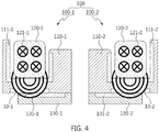
- FIG. 4 shows an exemplary air conditioner compressor shown in FIG. 1 after it is driven.
- the air conditioner compressor 100 when the air conditioner compressor 100 is operated (i.e., electric current is applied), magnetic force may be generated in the electromagnetic induction coils 121-1 and 121-2 and transmitted through the plastic composite structured pulleys 110-1 and 110-2 to the clutches 130-1 and 130-2.
- the pulleys and the clutches may come into contact with each other and driving force transmitted from an engine (not shown) may be transmitted to the air conditioner compressor so that the air conditioner compressor may be operated.
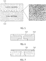
- FIG. 5 shows an exemplary steel-plastic composite according to an exemplary embodiment of the present invention.
- FIG. 5 shows another structure in manufacturing an exemplary clutches 130-1 and 130-2 shown in FIG. 1 .
- the clutch may be made by forming dimples on a surface of a steel material 510 and laminating the plastic composite on the dimpled surface of the steel material, for example, by means of injection molding, such that bonding force may be reinforced through enlargement of surface area.
- the dimples may be suitably formed on the top surface of the prepared steel material 510 by impacting steel balls or ceramic balls thereon by high-speed injection.
- the plastic composite 520 may be formed on the top surface of the steel material 510 by putting into a mold and injection molding the plastic in liquid phase containing the magnetic alloy powder and the steel material 510.
- a representation showing such a dimpled surface is illustrated as a partial enlarged view on the right side of the figure.
- FIGS. 6 to 8 show exemplary structures of an exemplary steel-plastic composite according to an exemplary embodiment of the present invention.
- shapes of plastic composites 620, 720 and 820 may be of reverse gradient shapes, i.e. a shape of a cross-section area of the plastic composite having an upper end longer than a lower end, so as to correspond to reverse gradient shapes formed inside the steel materials 610, 710 and 810, respectively.
- the plastic composite 620 shown in FIG. 6 may have an "I" shape cross-section area of which upper end may be longer than its lower end.
- the plastic composite 720 shown in FIG. 7 may have a "T" shape cross-section area that is getting wider toward its lower end.
- the plastic composite 820 shown in FIG. 8 may have a "T" shape cross-section area of which lower end is a hexagonal shape.
- FIG. 9 shows an exemplary process of manufacturing an exemplary plastic composite according to an exemplary embodiment of the present invention.
- magnetic alloy powder may be first prepared in step S910. Thereafter, the prepared magnetic alloy powder may be mixed with plastic in liquid phase to produce a mixture in step S920. The mixture may be then injected into a mold and injection molded to produce an exemplary plastic structure in steps S930 and S940.
- results of test confirming whether the clutch is driven or not while varying contents of Sm-Co magnetic powder and ferrite magnetic powder in an embodiment of the present invention are as follows: Table 1 Example Sm-Co magnetic powder (%) Content of ferrite magnetic powder (%) Total content of magnetic powder (%) Plastic injection molding Thickness (mm) Whether clutch is driven or not 1 10 9 19 3 Not operated 2 10 9.5 19.5 3 Not operated 3 10 10 20 3 Operated 4 10 10.5 20.5 3 Operated 5 10 11 21 3 Operated
- Examples 1 and 2 are comparative examples, while Examples 3 to 5 are inventive examples.
- the clutch may be driven while magnetic field was formed.
- Examples 1 and 2 are comparative examples, while Examples 3 to 5 are inventive examples.
- the thickness was 3t (i.e. 3 mm) or greater, the clutch was driven while magnetic field was formed.
Landscapes
- Engineering & Computer Science (AREA)
- Mechanical Engineering (AREA)
- General Engineering & Computer Science (AREA)
- Manufacturing & Machinery (AREA)
- Power Engineering (AREA)
- Chemical & Material Sciences (AREA)
- Physics & Mathematics (AREA)
- Composite Materials (AREA)
- Electromagnetism (AREA)
- Materials Engineering (AREA)
- Dispersion Chemistry (AREA)
- Pulleys (AREA)
- Compositions Of Macromolecular Compounds (AREA)
- Powder Metallurgy (AREA)
- Compressors, Vaccum Pumps And Other Relevant Systems (AREA)
- Compressor (AREA)
Abstract
Description
- The present invention relates to an air conditioner compressor including an aluminum pulley and a steel clutch, which includes plastic composites.
- In a general clutchless type variable compressor, a rotating body of the compressor composed of a swash plate, a hub and a rotor is always driven by rotational force transmitted from a pulley connected to an engine belt. However, power is continuously consumed even when an air conditioner is not turned on. Therefore, a clutch type variable compressor to which a clutch is added to increase driving efficiency of air conditioner compressors has been utilized.
- Such a clutch type variable compressor is composed of a steel pulley, a steel clutch, a frictional material formed on a bottom-end surface of the steel pulley, an electromagnetic induction coil and the like. In other words, it further includes the steel clutch to be incorporated between the steel pulley and the rotating body. Therefore, this type compressor may increase efficiency by eliminating unnecessary consumption of power, which may be wasted during rotation of the rotating body through cutting off power transmitted from the pulley to the rotating body when the air conditioner is not operated.
- However, in such clutch type variable compressor, the steel clutch is operated by magnetic field induced by the electromagnetic induction coil. Therefore, weight and/or cost may be increased due to addition of the electromagnetic induction coil and the steel clutch. Further, since the steel pulley also has to be magnetized, weight may not be reduced by changing a steel material to an aluminum material.
- In preferred aspects, the present invention provides a plastic composite including a magnetic alloy material replacing a steel material with an aluminum material to reduce weight and an air conditioner compressor including the same. Preferably, the magnetic alloy material may include a powder. The magnetic alloy material may be in a form of powder.
- Further, provided is a plastic composite containing magnetic alloy material may reducing weight and/or cost even when an electromagnetic induction coil and a clutch are included in an air conditioner compressor.
- In an aspect, provided is a plastic composite including a magnetic alloy material that can provide a way of replacing a steel material with an aluminum material to reduce weight.
- The term "magnetic" is meant by possessing a property that may be related to, or respond to a magnetism, for example, by earth's magnetic field or other magnetic materials, or to an electric field creating a magnetism. Exemplary magnetic property may be characterized by a ferromagnetic material, for example, iron, which may be used to producing a permanent magnet.
- The term "alloy" is meant by a metallic material including two or more of metal components, which may be bonded by metallic bond therebetween. In certain embodiments, the alloy may further include non-metallic elements such as carbon, sulfur, silicon, phosphorus, oxygen, or nitrogen, which may not be particularly limited. Exemplary alloy may contain iron or aluminum as main components constituting greater than about 90 % by weight, about 92 % by weight, about 95 % by weight or about 98 % by weight of the total weight of the alloy. In certain preferred embodiments, the alloy may be a steel alloy containing iron as a main component constituting greater than about 90 % by weight, about 92 % by weight, about 95 % by weight or about 98 % by weight of the total weight of the alloy.
- The plastic composite may suitably include the magnetic alloy material in an amount of about 20% by volume or greater on the basis of the total volume of the plastic composite.
- The magnetic alloy material may suitably include a ferrite magnetic powder. The ferrite magnetic powder may suitably include iron, cobalt, nickel or alloys thereof.
- The magnetic alloy material may further comprise rare earth-based magnetic alloy material.
- Further, the plastic composite may include the rare earth-based magnetic alloy material in an amount of about 10% by volume. The content of the ferrite magnetic powder may suitably be about 10 to 11% by volume.
- Further, the rare earth-based magnetic alloy material may be a rare earth-cobalt magnetic material.
- In an aspect of the present invention, provided is an air conditioner compressor that may include a pulley including the plastic composite as described above disposed inside thereof; and a clutch including a contact portion including the plastic composite in contact with a bottom-end surface of the pulley.
- In addition, a thinnest portion of a surface area adj acent to an electromagnetic induction coil may have a thickness of at least about 3 mm.
- In addition, the plastic composite may be formed inside the steel material and a shape of a cross-section area of the plastic composite may include an upper end longer than a lower end. Further, the shape may be an "I" shape of which the upper end is longer than the lower end, a "T" shape that is getting wider toward its lower end, or a "T" shape having a hexagonal shaped lower end.
- In an aspect, provided is a method of producing an air conditioner compressor. The method may include: applying the plastic composite as described above to a pulley of the air conditioner compressor to make a plastic composite structured pulley; and applying the plastic composite to a clutch of the air conditioner compressor to make a plastic composite structured clutch.
- The method may further include preparing the pulley by laminating the plastic composite on an aluminum material.
- The method may further include preparing the clutch by laminating the plastic composite on a surface of a straight plane of a steel material.
- Further, the method may include preparing the clutch by forming dimples on a surface of the steel material and laminating the plastic composite on the dimpled surface of the steel material by means of injection molding such that bonding force is reinforced through enlargement of surface area.
- The dimpled surface may be formed by injecting steel balls or ceramic balls at high speed.
- The plastic composite may be formed inside the steel material and a shape of a cross-section area of the plastic composite may include an upper end longer than a lower end. The shape may suitably have an "I" shape of which upper end is longer than its lower end, a "T" shape that is getting wider toward its lower end, or a "T" shape having a hexagonal shaped lower end.
- According to various exemplary embodiments of the present invention, weight of the clutch may be reduced, for example, by about 0.4 kg and weight of the pulley may be reduced, for example, by about 0.4 kg with the result that overall weight may be reduced, for example, by about 0.8 kg.
- In addition, shock noise (i.e., ticking noise) at a metallic interface and slipping phenomenon occurring when the clutch is driven may be improved and prevented.
- Further, the manufacturing cost may be reduced by virtue of downsizing the clutch, using the aluminum pulley, removing the frictional material and the like.
- It is to be understood that both the foregoing general description and the following detailed description of the present invention are exemplary and explanatory and are intended to provide further explanation of the invention as claimed.
- Other aspects of the invention are disclosed infra.
- The above and other objects, features and other advantages of the present invention will be more clearly understood from the following detailed description taken in conjunction with the accompanying drawings, in which:
-
FIG. 1 is an exemplary air conditioner compressor according to an exemplary embodiment of the present invention; -
FIG. 2 is a cross section of the plastic composite shown inFig. 1 ; -
FIG. 3 is an exemplary air conditioner compressor shown inFig. 1 before it is driven; -
FIG. 4 is an exemplary air conditioner compressor shown inFig. 1 after it is driven; -
FIG. 5 is an exemplary steel-plastic composite according to an exemplary embodiment of the present invention; -
FIG. 6 is an exemplary steel-plastic composite according to still an exemplary embodiment of the present invention; -
FIG. 7 is an exemplary steel-plastic composite according to an embodiment of the present invention; -
FIG. 8 is an exemplary steel-plastic composite according to an exemplary embodiment of the present invention; and -
FIG. 9 is a flowchart showing an exemplary process of manufacturing an exemplary plastic composite according to an exemplary embodiment of the present invention. - The terminology used herein is for the purpose of describing particular embodiments only and is not intended to be limiting. As used herein, the singular forms "a," "an" and "the" are intended to include the plural forms as well, unless the context clearly indicates otherwise. It will be further understood that the terms "comprise", "include", "have", etc. when used in this specification, specify the presence of stated features, regions, integers, steps, operations, elements and/or components but do not preclude the presence or addition of one or more other features, regions, integers, steps, operations, elements, components, and/or combinations thereof.
- It is understood that the term "vehicle" or "vehicular" or other similar term as used herein is inclusive of motor vehicles in general such as passenger automobiles including sports utility vehicles (SUV), buses, trucks, various commercial vehicles, watercraft including a variety of boats and ships, aircraft, and the like, and includes hybrid vehicles, electric vehicles, plug-in hybrid electric vehicles, hydrogen-powered vehicles and other alternative fuel vehicles (e.g. fuels derived from resources other than petroleum). As referred to herein, a hybrid vehicle is a vehicle that has two or more sources of power, for example both gasoline-powered and electric-powered vehicles.
- Further, unless specifically stated or obvious from context, as used herein, the term "about" is understood as within a range of normal tolerance in the art, for example within 2 standard deviations of the mean. "About" can be understood as within 10%, 9%, 8%, 7%, 6%, 5%, 4%, 3%, 2%, 1%, 0.5%, 0.1%, 0.05%, or 0.01% of the stated value. Unless otherwise clear from the context, all numerical values provided herein are modified by the term "about."
- Unless otherwise defined, all terms including technical and scientific terms used herein have the same meaning as commonly understood by one of ordinary skill in the art to which this invention belongs. It will be further understood that terms, such as those defined in commonly used dictionaries, should be interpreted as having a meaning that is consistent with their meaning in the context of the relevant art and the present disclosure, and will not be interpreted in an idealized or overly formal sense unless expressly so defined herein.
- Hereinafter, a plastic composite containing magnetic alloy material and an air conditioner compressor having the same, which are related to the present invention, will be described in detail with reference to the drawings. In this specification, the same or similar reference numerals are given to the same or similar configurations even in different embodiments and thus description thereof is replaced with the preceding description associated with them.
-
FIG. 1 shows an exemplaryair conditioner compressor 100 according to an exemplary embodiment of the present invention. As shown inFIG. 1 , theair conditioner compressor 100 may include a first assembly 100-1 and a second assembly 100-2. The first assembly 100-1 may include a first pulley 110-1 including a plastic composite 111-1 disposed inside thereof, a first core 120-1 including a first electromagnetic induction coil 121-1 disposed in an internal space of the first pulley 110-1, and a clutch 130-1 including a contact portion including a plastic composite 131-1 in contact with a bottom- end surface of the first pulley 110-1. - Similarly, the second assembly 100-2 may include a second pulley 110-2 including a plastic composite 111-2 disposed inside thereof, a second core 120-2 including a second electromagnetic induction coil 121-2 disposed in an internal space of the second plastic composite structured pulley 110-2, and a second clutch 130-2 including a contact portion including a plastic composite 131-2 in contact with a bottom-end surface of the second pulley 110-2. Preferably, magnetic forces 10-1, 10-2 may be generated when electric current is applied.
- The aluminum pulley may be a paramagnetic body and thus may not be utilized because it cannot transmit magnetic force being generated from the coil to the clutch. In order to complement this, the aluminum pulley may be made into a composite structure by injection molding plastic including ferromagnetic alloy material onto an aluminum body thereof. As such, a passage allowing magnetic force to be transmitted through the body of the aluminum pulley may be obtained so that the clutch may be normally driven.
- In addition, the steel clutch may be also made by injection molding the plastic including ferromagnetic alloy material which may be the same as or different from that in the aluminum pulley on a contact portion thereof in contact with the pulley so that response characteristic of the clutch may increase and any frictional material may be eliminated through improvement of slip characteristic.
- Particularly, each of the plastic composite members 111-1 and 111-2 may have a thickness of at least about 3t (e.g., about 3 mm) at the thinnest portion of a surface area adjacent to the electromagnetic induction coils 121-1 and 121-2. Therefore, the magnetic field formed by the electromagnetic induction coils 121-1 and 121-2 may be continuously transmitted.
-
FIG. 2 is a cross section of the plastic composites 111-1, 111-2, 131-1 and 131-2 shown inFIG. 1 . As shown inFIG. 2 , the plastic composite may be of a structure in which themagnetic alloy powder 210 may be impregnated into theplastic material 200. The plastic composites 111-1, 111-2, 131-1 and 131-2 may include the magnetic alloy powder of at least about 20% by volume on the basis of the volume of the plastic composite. Themagnetic alloy powder 210 may include iron, cobalt, nickel, or alloys thereof and the like. Preferably, a rare-earth magnet alloy powder may also be used. -
FIG. 3 shows an exemplaryair conditioner compressor 100 shown inFIG. 1 before it is driven. As shown inFIG. 3 , prior to operation of theair conditioner compressor 100, the pulleys 110-1 and 110-2 may be separated from the plastic composite structured clutches 130-1 and 130-2 so that the air conditioner compressor may not be driven. -
FIG. 4 shows an exemplary air conditioner compressor shown inFIG. 1 after it is driven. As shown inFIG. 4 , when theair conditioner compressor 100 is operated (i.e., electric current is applied), magnetic force may be generated in the electromagnetic induction coils 121-1 and 121-2 and transmitted through the plastic composite structured pulleys 110-1 and 110-2 to the clutches 130-1 and 130-2. As a result, the pulleys and the clutches may come into contact with each other and driving force transmitted from an engine (not shown) may be transmitted to the air conditioner compressor so that the air conditioner compressor may be operated. -
FIG. 5 shows an exemplary steel-plastic composite according to an exemplary embodiment of the present invention. In other words,FIG. 5 shows another structure in manufacturing an exemplary clutches 130-1 and 130-2 shown inFIG. 1 . As shown inFIG. 5 , the clutch may be made by forming dimples on a surface of asteel material 510 and laminating the plastic composite on the dimpled surface of the steel material, for example, by means of injection molding, such that bonding force may be reinforced through enlargement of surface area. The dimples may be suitably formed on the top surface of theprepared steel material 510 by impacting steel balls or ceramic balls thereon by high-speed injection. - The
plastic composite 520 may be formed on the top surface of thesteel material 510 by putting into a mold and injection molding the plastic in liquid phase containing the magnetic alloy powder and thesteel material 510. A representation showing such a dimpled surface is illustrated as a partial enlarged view on the right side of the figure. -
FIGS. 6 to 8 show exemplary structures of an exemplary steel-plastic composite according to an exemplary embodiment of the present invention. As shown inFIGS. 6 to 8 , shapes ofplastic composites steel materials - For example, the
plastic composite 620 shown inFIG. 6 may have an "I" shape cross-section area of which upper end may be longer than its lower end. The plastic composite 720 shown inFIG. 7 may have a "T" shape cross-section area that is getting wider toward its lower end. In addition, theplastic composite 820 shown inFIG. 8 may have a "T" shape cross-section area of which lower end is a hexagonal shape. -
FIG. 9 shows an exemplary process of manufacturing an exemplary plastic composite according to an exemplary embodiment of the present invention. As shown inFIG. 9 , magnetic alloy powder may be first prepared in step S910. Thereafter, the prepared magnetic alloy powder may be mixed with plastic in liquid phase to produce a mixture in step S920. The mixture may be then injected into a mold and injection molded to produce an exemplary plastic structure in steps S930 and S940. - Examples of the present invention will now be described in further detail along with comparative examples, but the present invention is not limited by the following examples.
- As inventive examples and comparative examples, results of test confirming whether the clutch is driven or not while varying contents of Sm-Co magnetic powder and ferrite magnetic powder in an embodiment of the present invention are as follows:
Table 1 Example Sm-Co magnetic powder (%) Content of ferrite magnetic powder (%) Total content of magnetic powder (%) Plastic injection molding Thickness (mm) Whether clutch is driven or not 1 10 9 19 3 Not operated 2 10 9.5 19.5 3 Not operated 3 10 10 20 3 Operated 4 10 10.5 20.5 3 Operated 5 10 11 21 3 Operated - In the Table 1 above, Examples 1 and 2 are comparative examples, while Examples 3 to 5 are inventive examples. As shown in the table above, when the total content of the magnetic powder was 20 % by volume or greater, the clutch may be driven while magnetic field was formed.
- The results of test for confirming whether the clutch was driven according to thickness of the plastic injection molding on condition that the minimum content of the magnetic powder was 20 % by volume are as follows:
Table 2 Example Sm-Co magnetic powder (%) Content of ferrite magnetic powder (%) Total content of magnetic powder (%) Plastic injection molding Thickness (mm) Whether clutch is driven or not 1 10 10 20 2.8 Not operated 2 10 10 20 2.9 Not operated 3 10 10 20 3 Operated 4 10 10 20 3.1 Operated 5 10 10 20 3.2 Operated - As shown in the Table above, Examples 1 and 2 are comparative examples, while Examples 3 to 5 are inventive examples. As shown in the Table 2, when the thickness was 3t (i.e. 3 mm) or greater, the clutch was driven while magnetic field was formed.
- While the present invention has been described with respect to the various exemplary embodiments, it will be apparent to those skilled in the art that various changes and modifications may be made without departing from the spirit and scope of the invention as defined in the following claims.
Claims (15)
- A plastic composite comprising an amount of about 20 % by volume or greater of a magnetic alloy material on the basis of the total volume of the plastic composite.
- The plastic composite of claim 1, wherein the magnetic alloy material is ferrite magnetic powder comprising iron, cobalt, nickel or alloys thereof.
- The plastic composite of claim 2, wherein the magnetic alloy material further comprises a rare earth-based magnetic alloy powder.
- The plastic composite of claim 3, wherein the rare earth-based magnetic alloy material comprises a rare earth-cobalt magnetic powder.
- An air conditioner compressor comprising:a pulley comprising a plastic composite; anda clutch comprising a contact portion comprising the plastic composite in contact with a bottom-end surface of the pulley,wherein the plastic composite is disposed inside the pulley and comprises an amount of about 20 % by volume or greater of a magnetic alloy material on the basis of the total volume of the plastic composite.
- The air conditioner compressor of claim 5, wherein a thinnest portion of a surface area adjacent to an electromagnetic induction coil has a thickness of at least about 3 mm.
- The air conditioner compressor of claim 5, wherein the plastic composite is formed inside a steel material and a shape of a cross-section area of the plastic composite comprises an upper end longer than a lower end.
- The air conditioner compressor of claim 7, wherein the shape comprises an "I" shape of which the upper end is longer than the lower end, a "T" shape that is getting wider toward its lower end, or a "T" shape having a hexagonal shaped lower end.
- The air conditioner compressor of claim 5, wherein the magnetic alloy material is ferrite magnetic powder comprising iron, cobalt, nickel or alloys thereof.
- The air conditioner compressor of claim 9, wherein the magnetic alloy material further comprises a rare earth-based magnetic alloy powder.
- The air conditioner compressor of claim 10, wherein the rare earth-based magnetic alloy material comprises a rare earth-cobalt magnetic powder.
- A method of producing an air conditioner compressor, comprising:applying a plastic composite to a pulley of the air conditioner compressor; andapplying the plastic composite to a clutch of the air conditioner compressor,wherein the plastic composite comprises an amount of about 20 % by volume or greater of a magnetic alloy material on the basis of the total volume of the plastic composite.
- The method of claim 12, further comprising,
preparing the pulley by laminating the plastic composite on an aluminum material; and
preparing the clutch by laminating the plastic composite on a surface of a straight plane of a steel material. - The method of claim 12, further comprising,
preparing the clutch by forming dimples on a surface of the steel material and laminating the plastic composite on the dimpled surface of the steel material, wherein the dimpled surface is formed by injecting steel balls or ceramic balls at high speed. - A vehicle comprising an air conditioner compressor manufactured by a method of claim 12.
Applications Claiming Priority (1)
| Application Number | Priority Date | Filing Date | Title |
|---|---|---|---|
| KR1020170183529A KR102359429B1 (en) | 2017-12-29 | 2017-12-29 | Complex body containing magnetic substance alloy powder, Air-conditioner compressor having the same, Method for manufacturing them |
Publications (3)
| Publication Number | Publication Date |
|---|---|
| EP3505273A2 true EP3505273A2 (en) | 2019-07-03 |
| EP3505273A3 EP3505273A3 (en) | 2019-07-31 |
| EP3505273B1 EP3505273B1 (en) | 2021-08-25 |
Family
ID=65019236
Family Applications (1)
| Application Number | Title | Priority Date | Filing Date |
|---|---|---|---|
| EP18212644.1A Active EP3505273B1 (en) | 2017-12-29 | 2018-12-14 | Plastic composite containing magnetic alloy powder, air conditioner compressor having the same and method of producing them |
Country Status (4)
| Country | Link |
|---|---|
| US (1) | US10975923B2 (en) |
| EP (1) | EP3505273B1 (en) |
| KR (1) | KR102359429B1 (en) |
| CN (1) | CN109994296B (en) |
Families Citing this family (2)
| Publication number | Priority date | Publication date | Assignee | Title |
|---|---|---|---|---|
| KR20240062348A (en) | 2022-10-31 | 2024-05-09 | 주식회사 성창오토텍 | Plastic composition for integrated controller housing |
| KR20250042028A (en) | 2023-09-19 | 2025-03-26 | 서준혁 | Server data distributed network storage system using distributed blockchain, including host node and main node |
Family Cites Families (19)
| Publication number | Priority date | Publication date | Assignee | Title |
|---|---|---|---|---|
| JPS6023697B2 (en) | 1977-06-15 | 1985-06-08 | 株式会社日立製作所 | Friction material and clutch motor |
| JPS54142451A (en) | 1978-04-28 | 1979-11-06 | Sanden Corp | Magnetic clutch |
| JPS5994405A (en) * | 1982-11-19 | 1984-05-31 | Seiko Epson Corp | Manufacturing method of resin bonded permanent magnet |
| JPS5986436U (en) | 1982-12-03 | 1984-06-11 | 内山工業株式会社 | Electromagnetic clutch and brake |
| JPS62209805A (en) * | 1986-03-10 | 1987-09-16 | Agency Of Ind Science & Technol | Molding method for composite magnetic material using zn-22al superplastic alloy powder |
| JP2524300B2 (en) * | 1993-06-22 | 1996-08-14 | 日精樹脂工業株式会社 | Plastic magnet injection molding machine |
| JP2516176B2 (en) * | 1993-12-24 | 1996-07-10 | セイコーエプソン株式会社 | Method for manufacturing resin-bonded permanent magnet |
| JP2000036403A (en) * | 1998-07-21 | 2000-02-02 | Seiko Epson Corp | Rare earth bonded magnet composition, rare earth bonded magnet, and method for manufacturing rare earth bonded magnet |
| JP3829974B2 (en) | 2000-06-09 | 2006-10-04 | 三菱化学株式会社 | Electrophotographic photoreceptor |
| JP2002078251A (en) | 2000-08-31 | 2002-03-15 | Mitsubishi Electric Corp | Electric motor |
| JP2003100509A (en) * | 2001-09-27 | 2003-04-04 | Nec Tokin Corp | Magnetic core and inductance part using the same |
| JP4561703B2 (en) | 2006-07-06 | 2010-10-13 | 株式会社デンソー | Face recognition device and automobile user hospitality system using the same |
| KR20080017227A (en) | 2006-08-21 | 2008-02-26 | 주식회사 디엔디테크 | Lamp lighting device for LCD backlight using conductive rubber and manufacturing method thereof |
| KR101289750B1 (en) | 2007-08-24 | 2013-07-26 | 한라비스테온공조 주식회사 | Electromagnetic clutch for compressor |
| JP5737334B2 (en) * | 2012-07-10 | 2015-06-17 | 株式会社デンソー | Method for adhering an adherend to an object to be coated, and adhering composite |
| JP6246500B2 (en) * | 2013-05-28 | 2017-12-13 | 日本電産サンキョー株式会社 | Rare earth magnet manufacturing method |
| KR101926880B1 (en) | 2013-11-20 | 2018-12-07 | 현대자동차주식회사 | Air Conditioner Compressor and Operation Method thereof |
| JP6260423B2 (en) * | 2014-04-15 | 2018-01-17 | 株式会社デンソー | clutch |
| KR101776827B1 (en) | 2015-12-14 | 2017-09-08 | 현대자동차주식회사 | The Unified Piston Of Airconditioner Compressor And Manufacturing Method Thereof |
-
2017
- 2017-12-29 KR KR1020170183529A patent/KR102359429B1/en active Active
-
2018
- 2018-12-10 US US16/214,319 patent/US10975923B2/en active Active
- 2018-12-13 CN CN201811528947.4A patent/CN109994296B/en active Active
- 2018-12-14 EP EP18212644.1A patent/EP3505273B1/en active Active
Non-Patent Citations (1)
| Title |
|---|
| None |
Also Published As
| Publication number | Publication date |
|---|---|
| CN109994296B (en) | 2023-12-22 |
| US10975923B2 (en) | 2021-04-13 |
| US20190203780A1 (en) | 2019-07-04 |
| EP3505273B1 (en) | 2021-08-25 |
| EP3505273A3 (en) | 2019-07-31 |
| KR20190081174A (en) | 2019-07-09 |
| CN109994296A (en) | 2019-07-09 |
| KR102359429B1 (en) | 2022-02-08 |
Similar Documents
| Publication | Publication Date | Title |
|---|---|---|
| US7847460B2 (en) | Yoke-integrated bonded magnet and magnet rotator for motor using the same | |
| KR102721666B1 (en) | Nd-Fe-B laminated sintered magnet and its manufacturing method | |
| KR100908424B1 (en) | Parts for magnetic circuits and manufacturing method thereof | |
| JP5267459B2 (en) | R-TM-B radial anisotropy ring magnet, manufacturing method thereof, mold for manufacturing the same, and rotor for brushless motor | |
| EP1722457A2 (en) | Motor | |
| CN108847723A (en) | It is layered magnet | |
| WO2006064589A1 (en) | Rotor for motor and manufacturing method of the same | |
| JP2012124189A (en) | Sintered magnet | |
| EP3505273B1 (en) | Plastic composite containing magnetic alloy powder, air conditioner compressor having the same and method of producing them | |
| WO2011106756A2 (en) | Improved magnet rotor assembly with increased physical strength | |
| US7967919B2 (en) | Process for producing self-assembled rare earth-iron bonded magnet and motor utilizing the same | |
| JP4581770B2 (en) | COMPOUND MAGNET, MOTOR, AND MANUFACTURING METHOD | |
| JP4900775B2 (en) | Rotor for motor and manufacturing method thereof | |
| EP1820587B1 (en) | Method for producing green compact and green compact | |
| JPH11186027A (en) | Radially-oriented magnetic anisotropic resin-bonded magnet and method for producing the same | |
| US20100321139A1 (en) | Permanent magnet and method of producing permanent magnet | |
| JP2002100522A (en) | Powder magnetic core having magnetic anisotropy and method for manufacturing the same | |
| US20140170014A1 (en) | Method for producing magnetic powder and magnet | |
| KR101406640B1 (en) | Motor core | |
| WO2023053307A1 (en) | Rotor and electric motor | |
| JPH07131957A (en) | Resin-bonded magnet rotor and method for manufacturing the same | |
| WO2025109656A1 (en) | Neodymium laminated sintered magnet | |
| Shimomura et al. | Latest Technical Trend for Miniaturization, Weight Reduction, and High Efficiency by Applying New Materials | |
| JP2024016680A (en) | neodymium laminated sintered magnet |
Legal Events
| Date | Code | Title | Description |
|---|---|---|---|
| PUAI | Public reference made under article 153(3) epc to a published international application that has entered the european phase |
Free format text: ORIGINAL CODE: 0009012 |
|
| STAA | Information on the status of an ep patent application or granted ep patent |
Free format text: STATUS: THE APPLICATION HAS BEEN PUBLISHED |
|
| PUAL | Search report despatched |
Free format text: ORIGINAL CODE: 0009013 |
|
| AK | Designated contracting states |
Kind code of ref document: A2 Designated state(s): AL AT BE BG CH CY CZ DE DK EE ES FI FR GB GR HR HU IE IS IT LI LT LU LV MC MK MT NL NO PL PT RO RS SE SI SK SM TR |
|
| AX | Request for extension of the european patent |
Extension state: BA ME |
|
| AK | Designated contracting states |
Kind code of ref document: A3 Designated state(s): AL AT BE BG CH CY CZ DE DK EE ES FI FR GB GR HR HU IE IS IT LI LT LU LV MC MK MT NL NO PL PT RO RS SE SI SK SM TR |
|
| AX | Request for extension of the european patent |
Extension state: BA ME |
|
| RIC1 | Information provided on ipc code assigned before grant |
Ipc: F04B 35/04 20060101ALI20190627BHEP Ipc: B22F 3/22 20060101ALI20190627BHEP Ipc: B22F 1/00 20060101AFI20190627BHEP Ipc: H01F 41/02 20060101ALI20190627BHEP Ipc: F16D 27/112 20060101ALI20190627BHEP Ipc: H01F 1/08 20060101ALI20190627BHEP Ipc: H01F 1/113 20060101ALI20190627BHEP Ipc: B22F 7/08 20060101ALI20190627BHEP Ipc: F04B 35/01 20060101ALI20190627BHEP Ipc: F16D 13/76 20060101ALI20190627BHEP Ipc: H01F 1/055 20060101ALI20190627BHEP Ipc: F16D 27/00 20060101ALI20190627BHEP Ipc: F16H 55/36 20060101ALI20190627BHEP Ipc: B22F 7/06 20060101ALI20190627BHEP |
|
| STAA | Information on the status of an ep patent application or granted ep patent |
Free format text: STATUS: REQUEST FOR EXAMINATION WAS MADE |
|
| 17P | Request for examination filed |
Effective date: 20200124 |
|
| RBV | Designated contracting states (corrected) |
Designated state(s): AL AT BE BG CH CY CZ DE DK EE ES FI FR GB GR HR HU IE IS IT LI LT LU LV MC MK MT NL NO PL PT RO RS SE SI SK SM TR |
|
| STAA | Information on the status of an ep patent application or granted ep patent |
Free format text: STATUS: EXAMINATION IS IN PROGRESS |
|
| 17Q | First examination report despatched |
Effective date: 20200420 |
|
| REG | Reference to a national code |
Ref country code: DE Ref legal event code: R079 Ref document number: 602018022327 Country of ref document: DE Free format text: PREVIOUS MAIN CLASS: B22F0001000000 Ipc: F04B0035010000 |
|
| RIC1 | Information provided on ipc code assigned before grant |
Ipc: H01F 1/055 20060101ALI20210312BHEP Ipc: F04B 35/04 20060101ALI20210312BHEP Ipc: F16D 27/112 20060101ALI20210312BHEP Ipc: F16H 55/36 20060101ALI20210312BHEP Ipc: H01F 1/113 20060101ALI20210312BHEP Ipc: B22F 7/08 20060101ALI20210312BHEP Ipc: B22F 3/22 20060101ALI20210312BHEP Ipc: B22F 1/00 20060101ALI20210312BHEP Ipc: F04B 35/01 20060101AFI20210312BHEP |
|
| RIC1 | Information provided on ipc code assigned before grant |
Ipc: H01F 1/055 20060101ALN20210319BHEP Ipc: F04B 35/04 20060101ALN20210319BHEP Ipc: F16D 27/112 20060101ALI20210319BHEP Ipc: F16H 55/36 20060101ALI20210319BHEP Ipc: H01F 1/113 20060101ALI20210319BHEP Ipc: B22F 7/08 20060101ALI20210319BHEP Ipc: B22F 3/22 20060101ALI20210319BHEP Ipc: B22F 1/00 20060101ALI20210319BHEP Ipc: F04B 35/01 20060101AFI20210319BHEP |
|
| GRAP | Despatch of communication of intention to grant a patent |
Free format text: ORIGINAL CODE: EPIDOSNIGR1 |
|
| STAA | Information on the status of an ep patent application or granted ep patent |
Free format text: STATUS: GRANT OF PATENT IS INTENDED |
|
| INTG | Intention to grant announced |
Effective date: 20210504 |
|
| GRAS | Grant fee paid |
Free format text: ORIGINAL CODE: EPIDOSNIGR3 |
|
| GRAA | (expected) grant |
Free format text: ORIGINAL CODE: 0009210 |
|
| STAA | Information on the status of an ep patent application or granted ep patent |
Free format text: STATUS: THE PATENT HAS BEEN GRANTED |
|
| RAP3 | Party data changed (applicant data changed or rights of an application transferred) |
Owner name: KIA CORPORATION Owner name: HYUNDAI MOTOR COMPANY |
|
| AK | Designated contracting states |
Kind code of ref document: B1 Designated state(s): AL AT BE BG CH CY CZ DE DK EE ES FI FR GB GR HR HU IE IS IT LI LT LU LV MC MK MT NL NO PL PT RO RS SE SI SK SM TR |
|
| REG | Reference to a national code |
Ref country code: CH Ref legal event code: EP |
|
| REG | Reference to a national code |
Ref country code: DE Ref legal event code: R096 Ref document number: 602018022327 Country of ref document: DE |
|
| REG | Reference to a national code |
Ref country code: IE Ref legal event code: FG4D Ref country code: AT Ref legal event code: REF Ref document number: 1424056 Country of ref document: AT Kind code of ref document: T Effective date: 20210915 |
|
| REG | Reference to a national code |
Ref country code: LT Ref legal event code: MG9D |
|
| REG | Reference to a national code |
Ref country code: NL Ref legal event code: MP Effective date: 20210825 |
|
| REG | Reference to a national code |
Ref country code: AT Ref legal event code: MK05 Ref document number: 1424056 Country of ref document: AT Kind code of ref document: T Effective date: 20210825 |
|
| PG25 | Lapsed in a contracting state [announced via postgrant information from national office to epo] |
Ref country code: SE Free format text: LAPSE BECAUSE OF FAILURE TO SUBMIT A TRANSLATION OF THE DESCRIPTION OR TO PAY THE FEE WITHIN THE PRESCRIBED TIME-LIMIT Effective date: 20210825 Ref country code: RS Free format text: LAPSE BECAUSE OF FAILURE TO SUBMIT A TRANSLATION OF THE DESCRIPTION OR TO PAY THE FEE WITHIN THE PRESCRIBED TIME-LIMIT Effective date: 20210825 Ref country code: HR Free format text: LAPSE BECAUSE OF FAILURE TO SUBMIT A TRANSLATION OF THE DESCRIPTION OR TO PAY THE FEE WITHIN THE PRESCRIBED TIME-LIMIT Effective date: 20210825 Ref country code: ES Free format text: LAPSE BECAUSE OF FAILURE TO SUBMIT A TRANSLATION OF THE DESCRIPTION OR TO PAY THE FEE WITHIN THE PRESCRIBED TIME-LIMIT Effective date: 20210825 Ref country code: FI Free format text: LAPSE BECAUSE OF FAILURE TO SUBMIT A TRANSLATION OF THE DESCRIPTION OR TO PAY THE FEE WITHIN THE PRESCRIBED TIME-LIMIT Effective date: 20210825 Ref country code: PT Free format text: LAPSE BECAUSE OF FAILURE TO SUBMIT A TRANSLATION OF THE DESCRIPTION OR TO PAY THE FEE WITHIN THE PRESCRIBED TIME-LIMIT Effective date: 20211227 Ref country code: NO Free format text: LAPSE BECAUSE OF FAILURE TO SUBMIT A TRANSLATION OF THE DESCRIPTION OR TO PAY THE FEE WITHIN THE PRESCRIBED TIME-LIMIT Effective date: 20211125 Ref country code: AT Free format text: LAPSE BECAUSE OF FAILURE TO SUBMIT A TRANSLATION OF THE DESCRIPTION OR TO PAY THE FEE WITHIN THE PRESCRIBED TIME-LIMIT Effective date: 20210825 Ref country code: BG Free format text: LAPSE BECAUSE OF FAILURE TO SUBMIT A TRANSLATION OF THE DESCRIPTION OR TO PAY THE FEE WITHIN THE PRESCRIBED TIME-LIMIT Effective date: 20211125 Ref country code: LT Free format text: LAPSE BECAUSE OF FAILURE TO SUBMIT A TRANSLATION OF THE DESCRIPTION OR TO PAY THE FEE WITHIN THE PRESCRIBED TIME-LIMIT Effective date: 20210825 |
|
| PG25 | Lapsed in a contracting state [announced via postgrant information from national office to epo] |
Ref country code: PL Free format text: LAPSE BECAUSE OF FAILURE TO SUBMIT A TRANSLATION OF THE DESCRIPTION OR TO PAY THE FEE WITHIN THE PRESCRIBED TIME-LIMIT Effective date: 20210825 Ref country code: LV Free format text: LAPSE BECAUSE OF FAILURE TO SUBMIT A TRANSLATION OF THE DESCRIPTION OR TO PAY THE FEE WITHIN THE PRESCRIBED TIME-LIMIT Effective date: 20210825 Ref country code: GR Free format text: LAPSE BECAUSE OF FAILURE TO SUBMIT A TRANSLATION OF THE DESCRIPTION OR TO PAY THE FEE WITHIN THE PRESCRIBED TIME-LIMIT Effective date: 20211126 |
|
| PG25 | Lapsed in a contracting state [announced via postgrant information from national office to epo] |
Ref country code: NL Free format text: LAPSE BECAUSE OF FAILURE TO SUBMIT A TRANSLATION OF THE DESCRIPTION OR TO PAY THE FEE WITHIN THE PRESCRIBED TIME-LIMIT Effective date: 20210825 |
|
| PG25 | Lapsed in a contracting state [announced via postgrant information from national office to epo] |
Ref country code: DK Free format text: LAPSE BECAUSE OF FAILURE TO SUBMIT A TRANSLATION OF THE DESCRIPTION OR TO PAY THE FEE WITHIN THE PRESCRIBED TIME-LIMIT Effective date: 20210825 |
|
| REG | Reference to a national code |
Ref country code: DE Ref legal event code: R097 Ref document number: 602018022327 Country of ref document: DE |
|
| PG25 | Lapsed in a contracting state [announced via postgrant information from national office to epo] |
Ref country code: SM Free format text: LAPSE BECAUSE OF FAILURE TO SUBMIT A TRANSLATION OF THE DESCRIPTION OR TO PAY THE FEE WITHIN THE PRESCRIBED TIME-LIMIT Effective date: 20210825 Ref country code: SK Free format text: LAPSE BECAUSE OF FAILURE TO SUBMIT A TRANSLATION OF THE DESCRIPTION OR TO PAY THE FEE WITHIN THE PRESCRIBED TIME-LIMIT Effective date: 20210825 Ref country code: RO Free format text: LAPSE BECAUSE OF FAILURE TO SUBMIT A TRANSLATION OF THE DESCRIPTION OR TO PAY THE FEE WITHIN THE PRESCRIBED TIME-LIMIT Effective date: 20210825 Ref country code: EE Free format text: LAPSE BECAUSE OF FAILURE TO SUBMIT A TRANSLATION OF THE DESCRIPTION OR TO PAY THE FEE WITHIN THE PRESCRIBED TIME-LIMIT Effective date: 20210825 Ref country code: CZ Free format text: LAPSE BECAUSE OF FAILURE TO SUBMIT A TRANSLATION OF THE DESCRIPTION OR TO PAY THE FEE WITHIN THE PRESCRIBED TIME-LIMIT Effective date: 20210825 Ref country code: AL Free format text: LAPSE BECAUSE OF FAILURE TO SUBMIT A TRANSLATION OF THE DESCRIPTION OR TO PAY THE FEE WITHIN THE PRESCRIBED TIME-LIMIT Effective date: 20210825 |
|
| PLBE | No opposition filed within time limit |
Free format text: ORIGINAL CODE: 0009261 |
|
| STAA | Information on the status of an ep patent application or granted ep patent |
Free format text: STATUS: NO OPPOSITION FILED WITHIN TIME LIMIT |
|
| PG25 | Lapsed in a contracting state [announced via postgrant information from national office to epo] |
Ref country code: MC Free format text: LAPSE BECAUSE OF FAILURE TO SUBMIT A TRANSLATION OF THE DESCRIPTION OR TO PAY THE FEE WITHIN THE PRESCRIBED TIME-LIMIT Effective date: 20210825 Ref country code: IT Free format text: LAPSE BECAUSE OF FAILURE TO SUBMIT A TRANSLATION OF THE DESCRIPTION OR TO PAY THE FEE WITHIN THE PRESCRIBED TIME-LIMIT Effective date: 20210825 |
|
| REG | Reference to a national code |
Ref country code: CH Ref legal event code: PL |
|
| 26N | No opposition filed |
Effective date: 20220527 |
|
| PG25 | Lapsed in a contracting state [announced via postgrant information from national office to epo] |
Ref country code: SI Free format text: LAPSE BECAUSE OF FAILURE TO SUBMIT A TRANSLATION OF THE DESCRIPTION OR TO PAY THE FEE WITHIN THE PRESCRIBED TIME-LIMIT Effective date: 20210825 |
|
| REG | Reference to a national code |
Ref country code: BE Ref legal event code: MM Effective date: 20211231 |
|
| PG25 | Lapsed in a contracting state [announced via postgrant information from national office to epo] |
Ref country code: LU Free format text: LAPSE BECAUSE OF NON-PAYMENT OF DUE FEES Effective date: 20211214 Ref country code: IE Free format text: LAPSE BECAUSE OF NON-PAYMENT OF DUE FEES Effective date: 20211214 |
|
| PG25 | Lapsed in a contracting state [announced via postgrant information from national office to epo] |
Ref country code: BE Free format text: LAPSE BECAUSE OF NON-PAYMENT OF DUE FEES Effective date: 20211231 |
|
| PG25 | Lapsed in a contracting state [announced via postgrant information from national office to epo] |
Ref country code: LI Free format text: LAPSE BECAUSE OF NON-PAYMENT OF DUE FEES Effective date: 20211231 Ref country code: CH Free format text: LAPSE BECAUSE OF NON-PAYMENT OF DUE FEES Effective date: 20211231 |
|
| P01 | Opt-out of the competence of the unified patent court (upc) registered |
Effective date: 20230512 |
|
| PG25 | Lapsed in a contracting state [announced via postgrant information from national office to epo] |
Ref country code: CY Free format text: LAPSE BECAUSE OF FAILURE TO SUBMIT A TRANSLATION OF THE DESCRIPTION OR TO PAY THE FEE WITHIN THE PRESCRIBED TIME-LIMIT Effective date: 20210825 |
|
| PG25 | Lapsed in a contracting state [announced via postgrant information from national office to epo] |
Ref country code: HU Free format text: LAPSE BECAUSE OF FAILURE TO SUBMIT A TRANSLATION OF THE DESCRIPTION OR TO PAY THE FEE WITHIN THE PRESCRIBED TIME-LIMIT; INVALID AB INITIO Effective date: 20181214 |
|
| PGFP | Annual fee paid to national office [announced via postgrant information from national office to epo] |
Ref country code: GB Payment date: 20231120 Year of fee payment: 6 |
|
| PGFP | Annual fee paid to national office [announced via postgrant information from national office to epo] |
Ref country code: FR Payment date: 20231121 Year of fee payment: 6 |
|
| PG25 | Lapsed in a contracting state [announced via postgrant information from national office to epo] |
Ref country code: MK Free format text: LAPSE BECAUSE OF FAILURE TO SUBMIT A TRANSLATION OF THE DESCRIPTION OR TO PAY THE FEE WITHIN THE PRESCRIBED TIME-LIMIT Effective date: 20210825 |
|
| PG25 | Lapsed in a contracting state [announced via postgrant information from national office to epo] |
Ref country code: TR Free format text: LAPSE BECAUSE OF FAILURE TO SUBMIT A TRANSLATION OF THE DESCRIPTION OR TO PAY THE FEE WITHIN THE PRESCRIBED TIME-LIMIT Effective date: 20210825 |
|
| PG25 | Lapsed in a contracting state [announced via postgrant information from national office to epo] |
Ref country code: MT Free format text: LAPSE BECAUSE OF FAILURE TO SUBMIT A TRANSLATION OF THE DESCRIPTION OR TO PAY THE FEE WITHIN THE PRESCRIBED TIME-LIMIT Effective date: 20210825 |
|
| PGFP | Annual fee paid to national office [announced via postgrant information from national office to epo] |
Ref country code: DE Payment date: 20241121 Year of fee payment: 7 |
|
| GBPC | Gb: european patent ceased through non-payment of renewal fee |
Effective date: 20241214 |
|
| PG25 | Lapsed in a contracting state [announced via postgrant information from national office to epo] |
Ref country code: GB Free format text: LAPSE BECAUSE OF NON-PAYMENT OF DUE FEES Effective date: 20241214 |
|
| PG25 | Lapsed in a contracting state [announced via postgrant information from national office to epo] |
Ref country code: FR Free format text: LAPSE BECAUSE OF NON-PAYMENT OF DUE FEES Effective date: 20241231 |