EP3505269B1 - Forging device for additive manufacturing system - Google Patents
Forging device for additive manufacturing system Download PDFInfo
- Publication number
- EP3505269B1 EP3505269B1 EP18214655.5A EP18214655A EP3505269B1 EP 3505269 B1 EP3505269 B1 EP 3505269B1 EP 18214655 A EP18214655 A EP 18214655A EP 3505269 B1 EP3505269 B1 EP 3505269B1
- Authority
- EP
- European Patent Office
- Prior art keywords
- forging
- cladding layer
- head
- forging head
- additive manufacturing
- Prior art date
- Legal status (The legal status is an assumption and is not a legal conclusion. Google has not performed a legal analysis and makes no representation as to the accuracy of the status listed.)
- Active
Links
Images




Classifications
-
- B—PERFORMING OPERATIONS; TRANSPORTING
- B22—CASTING; POWDER METALLURGY
- B22F—WORKING METALLIC POWDER; MANUFACTURE OF ARTICLES FROM METALLIC POWDER; MAKING METALLIC POWDER; APPARATUS OR DEVICES SPECIALLY ADAPTED FOR METALLIC POWDER
- B22F3/00—Manufacture of workpieces or articles from metallic powder characterised by the manner of compacting or sintering; Apparatus specially adapted therefor ; Presses and furnaces
- B22F3/17—Manufacture of workpieces or articles from metallic powder characterised by the manner of compacting or sintering; Apparatus specially adapted therefor ; Presses and furnaces by forging
-
- B—PERFORMING OPERATIONS; TRANSPORTING
- B21—MECHANICAL METAL-WORKING WITHOUT ESSENTIALLY REMOVING MATERIAL; PUNCHING METAL
- B21J—FORGING; HAMMERING; PRESSING METAL; RIVETING; FORGE FURNACES
- B21J1/00—Preparing metal stock or similar ancillary operations prior, during or post forging, e.g. heating or cooling
- B21J1/06—Heating or cooling methods or arrangements specially adapted for performing forging or pressing operations
-
- B—PERFORMING OPERATIONS; TRANSPORTING
- B21—MECHANICAL METAL-WORKING WITHOUT ESSENTIALLY REMOVING MATERIAL; PUNCHING METAL
- B21J—FORGING; HAMMERING; PRESSING METAL; RIVETING; FORGE FURNACES
- B21J13/00—Details of machines for forging, pressing, or hammering
- B21J13/02—Dies or mountings therefor
-
- B—PERFORMING OPERATIONS; TRANSPORTING
- B21—MECHANICAL METAL-WORKING WITHOUT ESSENTIALLY REMOVING MATERIAL; PUNCHING METAL
- B21J—FORGING; HAMMERING; PRESSING METAL; RIVETING; FORGE FURNACES
- B21J13/00—Details of machines for forging, pressing, or hammering
- B21J13/06—Hammers tups; Anvils; Anvil blocks
-
- B—PERFORMING OPERATIONS; TRANSPORTING
- B21—MECHANICAL METAL-WORKING WITHOUT ESSENTIALLY REMOVING MATERIAL; PUNCHING METAL
- B21J—FORGING; HAMMERING; PRESSING METAL; RIVETING; FORGE FURNACES
- B21J5/00—Methods for forging, hammering, or pressing; Special equipment or accessories therefor
- B21J5/002—Hybrid process, e.g. forging following casting
-
- B—PERFORMING OPERATIONS; TRANSPORTING
- B21—MECHANICAL METAL-WORKING WITHOUT ESSENTIALLY REMOVING MATERIAL; PUNCHING METAL
- B21J—FORGING; HAMMERING; PRESSING METAL; RIVETING; FORGE FURNACES
- B21J7/00—Hammers; Forging machines with hammers or die jaws acting by impact
- B21J7/02—Special design or construction
-
- B—PERFORMING OPERATIONS; TRANSPORTING
- B21—MECHANICAL METAL-WORKING WITHOUT ESSENTIALLY REMOVING MATERIAL; PUNCHING METAL
- B21J—FORGING; HAMMERING; PRESSING METAL; RIVETING; FORGE FURNACES
- B21J9/00—Forging presses
- B21J9/02—Special design or construction
-
- B—PERFORMING OPERATIONS; TRANSPORTING
- B21—MECHANICAL METAL-WORKING WITHOUT ESSENTIALLY REMOVING MATERIAL; PUNCHING METAL
- B21J—FORGING; HAMMERING; PRESSING METAL; RIVETING; FORGE FURNACES
- B21J9/00—Forging presses
- B21J9/10—Drives for forging presses
- B21J9/18—Drives for forging presses operated by making use of gearing mechanisms, e.g. levers, spindles, crankshafts, eccentrics, toggle-levers, rack bars
-
- B—PERFORMING OPERATIONS; TRANSPORTING
- B22—CASTING; POWDER METALLURGY
- B22F—WORKING METALLIC POWDER; MANUFACTURE OF ARTICLES FROM METALLIC POWDER; MAKING METALLIC POWDER; APPARATUS OR DEVICES SPECIALLY ADAPTED FOR METALLIC POWDER
- B22F10/00—Additive manufacturing of workpieces or articles from metallic powder
- B22F10/20—Direct sintering or melting
- B22F10/25—Direct deposition of metal particles, e.g. direct metal deposition [DMD] or laser engineered net shaping [LENS]
-
- B—PERFORMING OPERATIONS; TRANSPORTING
- B22—CASTING; POWDER METALLURGY
- B22F—WORKING METALLIC POWDER; MANUFACTURE OF ARTICLES FROM METALLIC POWDER; MAKING METALLIC POWDER; APPARATUS OR DEVICES SPECIALLY ADAPTED FOR METALLIC POWDER
- B22F10/00—Additive manufacturing of workpieces or articles from metallic powder
- B22F10/50—Treatment of workpieces or articles during build-up, e.g. treatments applied to fused layers during build-up
-
- B—PERFORMING OPERATIONS; TRANSPORTING
- B22—CASTING; POWDER METALLURGY
- B22F—WORKING METALLIC POWDER; MANUFACTURE OF ARTICLES FROM METALLIC POWDER; MAKING METALLIC POWDER; APPARATUS OR DEVICES SPECIALLY ADAPTED FOR METALLIC POWDER
- B22F12/00—Apparatus or devices specially adapted for additive manufacturing; Auxiliary means for additive manufacturing; Combinations of additive manufacturing apparatus or devices with other processing apparatus or devices
- B22F12/20—Cooling means
-
- B—PERFORMING OPERATIONS; TRANSPORTING
- B22—CASTING; POWDER METALLURGY
- B22F—WORKING METALLIC POWDER; MANUFACTURE OF ARTICLES FROM METALLIC POWDER; MAKING METALLIC POWDER; APPARATUS OR DEVICES SPECIALLY ADAPTED FOR METALLIC POWDER
- B22F12/00—Apparatus or devices specially adapted for additive manufacturing; Auxiliary means for additive manufacturing; Combinations of additive manufacturing apparatus or devices with other processing apparatus or devices
- B22F12/80—Plants, production lines or modules
- B22F12/82—Combination of additive manufacturing apparatus or devices with other processing apparatus or devices
-
- B—PERFORMING OPERATIONS; TRANSPORTING
- B22—CASTING; POWDER METALLURGY
- B22F—WORKING METALLIC POWDER; MANUFACTURE OF ARTICLES FROM METALLIC POWDER; MAKING METALLIC POWDER; APPARATUS OR DEVICES SPECIALLY ADAPTED FOR METALLIC POWDER
- B22F3/00—Manufacture of workpieces or articles from metallic powder characterised by the manner of compacting or sintering; Apparatus specially adapted therefor ; Presses and furnaces
- B22F3/24—After-treatment of workpieces or articles
-
- B—PERFORMING OPERATIONS; TRANSPORTING
- B23—MACHINE TOOLS; METAL-WORKING NOT OTHERWISE PROVIDED FOR
- B23K—SOLDERING OR UNSOLDERING; WELDING; CLADDING OR PLATING BY SOLDERING OR WELDING; CUTTING BY APPLYING HEAT LOCALLY, e.g. FLAME CUTTING; WORKING BY LASER BEAM
- B23K26/00—Working by laser beam, e.g. welding, cutting or boring
- B23K26/0093—Working by laser beam, e.g. welding, cutting or boring combined with mechanical machining or metal-working covered by other subclasses than B23K
-
- B—PERFORMING OPERATIONS; TRANSPORTING
- B23—MACHINE TOOLS; METAL-WORKING NOT OTHERWISE PROVIDED FOR
- B23K—SOLDERING OR UNSOLDERING; WELDING; CLADDING OR PLATING BY SOLDERING OR WELDING; CUTTING BY APPLYING HEAT LOCALLY, e.g. FLAME CUTTING; WORKING BY LASER BEAM
- B23K26/00—Working by laser beam, e.g. welding, cutting or boring
- B23K26/34—Laser welding for purposes other than joining
- B23K26/342—Build-up welding
-
- B—PERFORMING OPERATIONS; TRANSPORTING
- B23—MACHINE TOOLS; METAL-WORKING NOT OTHERWISE PROVIDED FOR
- B23K—SOLDERING OR UNSOLDERING; WELDING; CLADDING OR PLATING BY SOLDERING OR WELDING; CUTTING BY APPLYING HEAT LOCALLY, e.g. FLAME CUTTING; WORKING BY LASER BEAM
- B23K9/00—Arc welding or cutting
- B23K9/04—Welding for other purposes than joining, e.g. built-up welding
-
- B—PERFORMING OPERATIONS; TRANSPORTING
- B33—ADDITIVE MANUFACTURING TECHNOLOGY
- B33Y—ADDITIVE MANUFACTURING, i.e. MANUFACTURING OF THREE-DIMENSIONAL [3D] OBJECTS BY ADDITIVE DEPOSITION, ADDITIVE AGGLOMERATION OR ADDITIVE LAYERING, e.g. BY 3D PRINTING, STEREOLITHOGRAPHY OR SELECTIVE LASER SINTERING
- B33Y10/00—Processes of additive manufacturing
-
- B—PERFORMING OPERATIONS; TRANSPORTING
- B33—ADDITIVE MANUFACTURING TECHNOLOGY
- B33Y—ADDITIVE MANUFACTURING, i.e. MANUFACTURING OF THREE-DIMENSIONAL [3D] OBJECTS BY ADDITIVE DEPOSITION, ADDITIVE AGGLOMERATION OR ADDITIVE LAYERING, e.g. BY 3D PRINTING, STEREOLITHOGRAPHY OR SELECTIVE LASER SINTERING
- B33Y30/00—Apparatus for additive manufacturing; Details thereof or accessories therefor
-
- B—PERFORMING OPERATIONS; TRANSPORTING
- B33—ADDITIVE MANUFACTURING TECHNOLOGY
- B33Y—ADDITIVE MANUFACTURING, i.e. MANUFACTURING OF THREE-DIMENSIONAL [3D] OBJECTS BY ADDITIVE DEPOSITION, ADDITIVE AGGLOMERATION OR ADDITIVE LAYERING, e.g. BY 3D PRINTING, STEREOLITHOGRAPHY OR SELECTIVE LASER SINTERING
- B33Y40/00—Auxiliary operations or equipment, e.g. for material handling
-
- B—PERFORMING OPERATIONS; TRANSPORTING
- B33—ADDITIVE MANUFACTURING TECHNOLOGY
- B33Y—ADDITIVE MANUFACTURING, i.e. MANUFACTURING OF THREE-DIMENSIONAL [3D] OBJECTS BY ADDITIVE DEPOSITION, ADDITIVE AGGLOMERATION OR ADDITIVE LAYERING, e.g. BY 3D PRINTING, STEREOLITHOGRAPHY OR SELECTIVE LASER SINTERING
- B33Y80/00—Products made by additive manufacturing
-
- C—CHEMISTRY; METALLURGY
- C23—COATING METALLIC MATERIAL; COATING MATERIAL WITH METALLIC MATERIAL; CHEMICAL SURFACE TREATMENT; DIFFUSION TREATMENT OF METALLIC MATERIAL; COATING BY VACUUM EVAPORATION, BY SPUTTERING, BY ION IMPLANTATION OR BY CHEMICAL VAPOUR DEPOSITION, IN GENERAL; INHIBITING CORROSION OF METALLIC MATERIAL OR INCRUSTATION IN GENERAL
- C23C—COATING METALLIC MATERIAL; COATING MATERIAL WITH METALLIC MATERIAL; SURFACE TREATMENT OF METALLIC MATERIAL BY DIFFUSION INTO THE SURFACE, BY CHEMICAL CONVERSION OR SUBSTITUTION; COATING BY VACUUM EVAPORATION, BY SPUTTERING, BY ION IMPLANTATION OR BY CHEMICAL VAPOUR DEPOSITION, IN GENERAL
- C23C24/00—Coating starting from inorganic powder
- C23C24/08—Coating starting from inorganic powder by application of heat or pressure and heat
- C23C24/10—Coating starting from inorganic powder by application of heat or pressure and heat with intermediate formation of a liquid phase in the layer
-
- B—PERFORMING OPERATIONS; TRANSPORTING
- B22—CASTING; POWDER METALLURGY
- B22F—WORKING METALLIC POWDER; MANUFACTURE OF ARTICLES FROM METALLIC POWDER; MAKING METALLIC POWDER; APPARATUS OR DEVICES SPECIALLY ADAPTED FOR METALLIC POWDER
- B22F10/00—Additive manufacturing of workpieces or articles from metallic powder
- B22F10/30—Process control
- B22F10/38—Process control to achieve specific product aspects, e.g. surface smoothness, density, porosity or hollow structures
-
- B—PERFORMING OPERATIONS; TRANSPORTING
- B22—CASTING; POWDER METALLURGY
- B22F—WORKING METALLIC POWDER; MANUFACTURE OF ARTICLES FROM METALLIC POWDER; MAKING METALLIC POWDER; APPARATUS OR DEVICES SPECIALLY ADAPTED FOR METALLIC POWDER
- B22F2999/00—Aspects linked to processes or compositions used in powder metallurgy
-
- B—PERFORMING OPERATIONS; TRANSPORTING
- B23—MACHINE TOOLS; METAL-WORKING NOT OTHERWISE PROVIDED FOR
- B23K—SOLDERING OR UNSOLDERING; WELDING; CLADDING OR PLATING BY SOLDERING OR WELDING; CUTTING BY APPLYING HEAT LOCALLY, e.g. FLAME CUTTING; WORKING BY LASER BEAM
- B23K15/00—Electron-beam welding or cutting
- B23K15/0046—Welding
- B23K15/0086—Welding welding for purposes other than joining, e.g. build-up welding
-
- B—PERFORMING OPERATIONS; TRANSPORTING
- B33—ADDITIVE MANUFACTURING TECHNOLOGY
- B33Y—ADDITIVE MANUFACTURING, i.e. MANUFACTURING OF THREE-DIMENSIONAL [3D] OBJECTS BY ADDITIVE DEPOSITION, ADDITIVE AGGLOMERATION OR ADDITIVE LAYERING, e.g. BY 3D PRINTING, STEREOLITHOGRAPHY OR SELECTIVE LASER SINTERING
- B33Y70/00—Materials specially adapted for additive manufacturing
-
- C—CHEMISTRY; METALLURGY
- C22—METALLURGY; FERROUS OR NON-FERROUS ALLOYS; TREATMENT OF ALLOYS OR NON-FERROUS METALS
- C22C—ALLOYS
- C22C19/00—Alloys based on nickel or cobalt
- C22C19/03—Alloys based on nickel or cobalt based on nickel
-
- C—CHEMISTRY; METALLURGY
- C22—METALLURGY; FERROUS OR NON-FERROUS ALLOYS; TREATMENT OF ALLOYS OR NON-FERROUS METALS
- C22C—ALLOYS
- C22C19/00—Alloys based on nickel or cobalt
- C22C19/03—Alloys based on nickel or cobalt based on nickel
- C22C19/05—Alloys based on nickel or cobalt based on nickel with chromium
- C22C19/051—Alloys based on nickel or cobalt based on nickel with chromium and Mo or W
-
- C—CHEMISTRY; METALLURGY
- C22—METALLURGY; FERROUS OR NON-FERROUS ALLOYS; TREATMENT OF ALLOYS OR NON-FERROUS METALS
- C22C—ALLOYS
- C22C29/00—Alloys based on carbides, oxides, nitrides, borides, or silicides, e.g. cermets, or other metal compounds, e.g. oxynitrides, sulfides
- C22C29/02—Alloys based on carbides, oxides, nitrides, borides, or silicides, e.g. cermets, or other metal compounds, e.g. oxynitrides, sulfides based on carbides or carbonitrides
- C22C29/06—Alloys based on carbides, oxides, nitrides, borides, or silicides, e.g. cermets, or other metal compounds, e.g. oxynitrides, sulfides based on carbides or carbonitrides based on carbides, but not containing other metal compounds
- C22C29/08—Alloys based on carbides, oxides, nitrides, borides, or silicides, e.g. cermets, or other metal compounds, e.g. oxynitrides, sulfides based on carbides or carbonitrides based on carbides, but not containing other metal compounds based on tungsten carbide
-
- Y—GENERAL TAGGING OF NEW TECHNOLOGICAL DEVELOPMENTS; GENERAL TAGGING OF CROSS-SECTIONAL TECHNOLOGIES SPANNING OVER SEVERAL SECTIONS OF THE IPC; TECHNICAL SUBJECTS COVERED BY FORMER USPC CROSS-REFERENCE ART COLLECTIONS [XRACs] AND DIGESTS
- Y02—TECHNOLOGIES OR APPLICATIONS FOR MITIGATION OR ADAPTATION AGAINST CLIMATE CHANGE
- Y02P—CLIMATE CHANGE MITIGATION TECHNOLOGIES IN THE PRODUCTION OR PROCESSING OF GOODS
- Y02P10/00—Technologies related to metal processing
- Y02P10/25—Process efficiency
Definitions
- the present invention relates to a forging device suitable for additive manufacturing, and an additive manufacturing system using the forging device.
- Additive manufacturing technology is a rapidly evolving emerging technology for material processing.
- the mainstream additive manufacturing usually achieves metallurgical bonding of metal materials through the "melting-solidification" method, which is characterized by using a high-energy beam such as a laser beam, an electron beam or an arc beam as a heat source to melt the synchronously fed metal material, such as metal powder, metal wire, and so on, which arc stacked in layers, whereby parts are manufactured by surfacing, and the internal microstructure of the obtained parts is a solidified structure.
- the solidified structure obtained by the above-mentioned "melting-solidification” method produces crystals that are very coarse with obvious directionality, therefore in a general sense, it is difficult to achieve comprehensive performance comparable to that of a forged material.
- a method of combining the molten deposition additive with thermomechanical processing has been gradually developed, that is, material deposition and metallurgical bonding are achieved by melting-solidification, thereafter rolling, shock processing and other treatments are used to refine the grains and improve internal quality.
- the method of melting combined with forging can improve the internal quality as well as enhance performance to some extent, in this composite machining method, it is generally carried out under high temperature processing conditions.
- the forging head of the forging device (for example, the impacting member) needs to be forged under very high temperature and stress, which easily causes damage or scrapping of the forging head, affecting the efficiency of the entire additive manufacturing combined with the forging composite machining process.
- a forging head for additive manufacturing comprising: a base portion and a forging portion.
- the forging portion extends from the base portion for forging a cladding layer during formation of the cladding layer by additive manufacturing; the forging head further comprising a through hole which is formed through the base portion and the forging portion, for at least one of an energy bean and an additive material to pass through during formation of the cladding layer.
- a forging device for additive manufacturing comprising: a forging head and a forging head fixing device.
- the forging head comprises a base portion, a forging portion extending from the base portion, and a through hole formed through the base portion and the forging portion.
- the forging portion is configured for forging a cladding layer during formation of the cladding layer by additive manufacturing.
- the forging head fixing device comprising a cavity, for receiving the forging head.
- the through hole and the cavity communicate with each other, and are configured to allow at least one of an energy beam and an additive material to pass through during formation of the cladding layer.
- An additive manufacturing system comprising: an energy source and a forging device.
- the energy source is configured to provide an energy beam, for fusing at least a portion of a material added to a surface of the substrate for forming a cladding layer on the substrate or heating the cladding layer.
- the forging device comprises a forging head, for forging the cladding layer during formation of the cladding layer by additive manufacturing.
- the forging head comprises a base portion, a forging portion and a through hole formed through the base portion and the forging portion.
- the through hole is configured to allow at least one of an energy beam and an additive material to pass through during formation of the cladding layer.
- CN 107 287 588 A discloses a forging apparatus for a laser cladding system.
- the present invention relates to a forging device for additive manufacturing, and an additive manufacturing system using the forging device.
- FIG. 1 shows a schematic view of a forging head 100 according to an embodiment of the present disclosure.
- the forging head 100 can be configured for additive manufacturing in combination with forging composite processes.
- the forging head 100 comprises a cylindrical base portion 101 and a forging portion 102 at the bottom of the base portion 101.
- the forging portion 102 extends from the bottom of the base portion 101 for forging a cladding layer during formation of the cladding layer by additive manufacturing.
- the forging head 100 further comprises a through hole 103 formed through the base portion 101 and the forging portion 102.
- the through hole 103 has a straight cylindrical shape, and is configured to allow at least one of an energy beam and an additive material of the additive manufacturing system to pass through during formation of the cladding layer.
- the forging portion 102 comprises a substantially flat forging surface 104 for contacting the cladding layer.
- the forging portion 102 is located on one side of the through hole 103.
- the forging head 100 also forms a plurality of grooves 106 on the base portion 101 by cutting a portion of the cylindrical base portion 101 in a direction toward the top end of the base portion 101 to form a plurality of step portions 105 adjacent to a top end thereof.
- the step portion 105 can be fixed to the forging head fixing device by mating with the fastener.
- the forging head 100 can move along the trajectory of the additive manufacturing system to form the cladding layer.
- the forging portion 102 can forge the cladding layer in real time during the formation of the cladding layer, thereby achieving peening on the cladding layer, and eliminating defects such as holes, slip planes, and micro fractures in the cladding layer, thereby increasing the density of the final formed part.
- the microstructure of the final cladding layer can also be altered, such as to promote recrystallization of the cladding layer material and formation of fine equiaxed crystal structures.
- the forging surface 104 of the forging portion 102 of the forging head 100 is flat, which can increase the contact area with the cladding layer and improve the forging efficiency of the forging head 100.
- FIG. 2 shows a schematic view of a forging head 200 according to an embodiment of the present disclosure.
- the forging head 200 can be configured for additive manufacturing in combination with forging composite processes.
- the forging head 200 shown in FIG. 2 is substantially identical in construction to the forging head 100 of the embodiment shown in FIG. 1 , which also comprises a cylindrical base portion 201 and a forging portion 202 at the bottom of the base portion 201.
- the forging portion 202 extends from the bottom of the base portion 201 for forging a cladding layer during formation of the cladding layer by additive manufacturing.
- the forging head 200 also comprises a through hole 203 formed through the base portion 201 and the forging portion 202.
- the through hole 203 has a straight cylindrical shape, and is configured to allow at least one of an energy beam and an additive material of the additive manufacturing system to pass through during formation of the cladding layer.
- the forging portion 202 comprises a substantially flat forging surface 204 for contacting the cladding layer.
- the forging portion 202 is also located on one side of the through hole 203.
- the forging head 200 also forms a plurality of grooves 206 on the base portion 201 by cutting a portion of the cylindrical base portion 201 in a direction toward the top end of the base portion 201 to form a plurality of step portions 205 adjacent to a top end thereof.
- the step portion 205 can be fixed to the forging head fixing device by mating with the fastener.
- the forging head 200 is substantially identical in construction to the forging head 100 of the embodiment of FIG. 1 , which can move along the trajectory of the additive manufacturing system to form the cladding layer.
- the forging portion 202 can also forge the cladding layer in real time during the formation of the cladding layer, thereby achieving peening on the cladding layer, and eliminating defects such as holes, slip planes, and micro fractures in the cladding layer, thereby increasing the density of the final formed part.
- the microstructure of the final cladding layer can also be altered, such as to promote recrystallization of the cladding layer material and formation of fine equiaxed crystal structures.
- the main difference between the forging head 200 and the forging head 100 shown in the embodiment of FIG. 1 is that the forging surface 204 of the forging portion 202 of the forging head 200 is curved, which can increase the forged cladding layer; the stress in contact with the cladding layer is mainly applied to materials with high yield strength.
- FIG. 3 shows a schematic view of a forging head 300 according to an embodiment of the present disclosure.
- the forging head 300 can also be used in additive manufacturing in combination with forging composite processes.
- the forging head 300 shown in FIG. 3 is substantially identical to the forging head construction of the embodiment shown in FIGS. 1 and 2 , and also comprises a cylindrical base portion 301 and a forging portion 302 at the bottom of the base portion 301.
- the forging portion 302 extends from the bottom of the base portion 301 for forging a cladding layer during formation of the cladding layer by additive manufacturing.
- the forging head 300 also comprises a through hole 303 formed through the base portion 301 and the forging portion 302.
- the through hole 303 has a straight cylindrical shape, and is configured to allow at least one of an energy beam and an additive material of the additive manufacturing system to pass through during formation of the cladding layer.
- the forging portion 302 comprises a substantially flat forging surface 304 for contacting the cladding layer.
- the forging head 300 also forms a plurality of grooves 306 on the base portion 301 by cutting a portion of the cylindrical base portion 301 in a direction toward the top end of the base portion 301 to form a plurality of step portions 305 adjacent to a top end thereof.
- the step portion 305 can also be fixed to the forging head fixing device by mating with the fastener.
- the forging head 300 is substantially identical in structure to the forging head of the embodiments of FIG. 1 and FIG. 2 , which can move along the trajectory of the additive manufacturing system to form the cladding layer.
- the forging portion 302 can also forge the cladding layer in real time during the formation of the cladding layer, thereby achieving peening on the cladding layer, and eliminating defects such as holes, slip planes, and micro fractures in the cladding layer, thereby increasing the density of the final formed part.
- the microstructure of the final cladding layer can also be altered, such as to promote recrystallization of the cladding layer material and formation of fine equiaxed crystal structures.
- the main difference between the forging head 300 and the forging head 100 shown in the embodiment of FIG. 1 is that the forging portion 302 of the forging head 300 is symmetrically disposed on both sides of the through hole 303.
- the forging head 300 can forge the cladding layer in real time during the reciprocating movement along the trajectory of the additive manufacturing system to form the cladding layer, and the forging efficiency of the forging head 300 can be effectively improved.
- FIG. 4 shows a schematic view of a forging head 400 according to an embodiment of the present disclosure.
- the forging head 400 can also be used in additive manufacturing in combination with forging composite processes.
- the forging head 400 shown in FIG. 4 is substantially identical in construction to the forging head of the embodiment shown in FIGS. 1 to 3 , which also comprises a cylindrical base portion 401 and a forging portion 402 at the bottom of the base portion 401.
- the forging portion 402 extends from the bottom of the base portion 401 for forging a cladding layer during formation of the cladding layer by additive manufacturing.
- the forging head 400 also comprises a through hole 403 formed through the base portion 401 and the forging portion 402.
- the through hole 403 is configured to allow at least one of an energy beam and an additive material of the additive manufacturing system to pass through during formation of the cladding layer.
- the forging portion 402 comprises a substantially flat forging surface 404 for contacting the cladding layer.
- the forging head 400 also forms a plurality of grooves 406 on the base portion 401 by cutting a portion of the cylindrical base portion 401 in a direction toward the top end of the base portion 401 to form a plurality of step portions 405 adjacent to a top end thereof.
- the step portion 405 is also capable of fixing the forging head 400 to the forging head fixing device by mating with the fastener.
- the forging head 400 is substantially identical in construction to the forging head of the embodiment shown in FIGS. 1-3 , which can move along the trajectory of the additive manufacturing system to form the cladding layer.
- the forging portion 402 can also forge the cladding layer in real time during the formation of the cladding layer, thereby achieving peening on the cladding layer, and eliminating defects such as holes, slip planes, and micro fractures in the cladding layer, thereby increasing the density of the final formed part.
- the microstructure of the final cladding layer can also be altered, such as to promote recrystallization of the cladding layer material and formation of fine equiaxed crystal structures.
- the main difference between the forging head 400 and the forging head 100 shown in the embodiment of FIG. 1 is that the forging portion 402 of the forging head 400 is symmetrically disposed on both sides of the through hole 403, while the forging surface 404 of the forging portion 402 configured to come into contact with the cladding layer is curved.
- the forging head 400 can forge the cladding layer in real time during the reciprocating movement along the trajectory of the additive manufacturing system to form the cladding layer, and the forging efficiency of the forging head 400 can be effectively improved; at the same time, the curved forging surface 404 can increase the stress in contact with the cladding layer when the forging head forges the cladding layer, which is mainly suitable for materials with high yield strength.
- FIG. 5 it shows that the through hole 403 of the forging head 400 has a structure that is larger at the top and smaller at the bottom, with the longitudinal cross section of the through hole 403 having an inverted trapezoidal structure.
- the through hole 403 focuses of the additive material of the additive manufacturing system to avoid interference, while on the other hand, it is advantageous for increasing the forging portion of the forging head 400, such that the forging efficiency of the forging head can be correspondingly improved.
- FIG. 6 shows a schematic view of a forging head 500 according to an embodiment of the present disclosure.
- the forging head 500 can also be used in additive manufacturing in combination with forging composite processes.
- the forging head 500 shown in FIG. 6 is substantially identical in construction to the forging head of the embodiment shown in FIGS. 1 to 5 , which also comprises a cylindrical base portion 501 and a forging portion 502 at the bottom of the base portion 501.
- the forging portion 502 extends from the bottom of the base portion 501 for forging a cladding layer during formation of the cladding layer by additive manufacturing.
- the forging head 500 also comprises a through hole 503 formed through the base portion 501 and the forging portion 502.
- the through hole 503 is configured to allow at least one of an energy beam and an additive material of the additive manufacturing system to pass through during formation of the cladding layer.
- the forging portion 502 comprises a substantially flat forging surface 504 for contacting the cladding layer.
- the forging head 500 also forms a plurality of grooves 506 on the base portion 501 by cutting a portion of the cylindrical base portion 501 in a direction toward the top end of the base portion 501 to form a plurality of step portions 505 adjacent to a top end thereof.
- the step portion 505 is also capable of fixing the forging head 500 to the forging head fixing device by mating with the fastener.
- the forging head 500 is substantially identical in construction to the forging head of the embodiment of FIGS. 1-5 , which can move along the trajectory of the additive manufacturing system to form the cladding layer.
- the forging portion 502 can also forge the cladding layer in real time during the formation of the cladding layer, thereby achieving peening on the cladding layer, and eliminating defects such as holes, slip planes, and micro fractures in the cladding layer, thereby increasing the density of the final formed part.
- the microstructure of the final cladding layer can also be altered, such as to promote recrystallization of the cladding layer material and formation of fine equiaxed crystal structures.
- the main difference between the forging head 500 and the forging head 100 shown in the embodiment of FIG. 1 is that the forging portion 502 of the forging head 500 is formed by integrally extending from the bottom of the base portion 501 which also surrounds the through hole 503. Moreover, the entire forging surface 504 of the forging portion 502 in contact with the cladding layer is flat.
- the forging head 500 can forge the cladding layer in real time during the reciprocating movement along the trajectory of the additive manufacturing system to form the cladding layer or along the more complicated additive manufacturing cladding path; it can effectively improve the forging efficiency of the forging head 500, while the entire flat forging surface 504 can increase the area of contact with the cladding layer as the forging head is forging the cladding layer, which can also effectively improve the forging efficiency of the forging head.
- FIG. 7 shows a schematic view of a forging head 600 according to an embodiment of the present disclosure.
- the forging head 600 can also be used in additive manufacturing in combination with forging composite processes.
- the forging head 600 shown in FIG. 7 is substantially identical in construction to the forging head of the embodiment shown in FIGS. 1 to 6 , which also comprises a cylindrical base portion 601 and a forging portion 602 at the bottom of the base portion 601.
- the forging portion 602 extends from the bottom of the base portion 601 for forging a cladding layer during formation of the cladding layer by additive manufacturing.
- the forging head 600 also comprises a through hole 603 formed through the base portion 601 and the forging portion 602.
- the through hole 603 is configured to allow at least one of an energy beam and an additive material of the additive manufacturing system to pass through during formation of the cladding layer.
- the forging portion 602 comprises a substantially flat forging surface 604 for contacting the cladding layer.
- the forging head 600 also forms a plurality of grooves 606 on the base portion 601 by cutting a portion of the cylindrical base portion 601 in a direction toward the top end of the base portion 601 to form a plurality of step portions 605 adjacent to a top end thereof.
- the step portion 605 is also capable of fixing the forging head 600 to the forging head fixing device by mating with the fastener.
- the forging head 600 is substantially identical in construction to the forging head of the embodiment of FIGS. 1-6 , which can move along the trajectory of the additive manufacturing system to form the cladding layer.
- the forging portion 602 can also forge the cladding layer in real time during the formation of the cladding layer, thereby achieving peening on the cladding layer, and eliminating defects such as holes, slip planes, and micro fractures in the cladding layer, thereby increasing the density of the final formed part.
- the microstructure of the final cladding layer can also be altered, such as to promote recrystallization of the cladding layer material and formation of fine equiaxed crystal structures.
- the main difference between the forging head 600 and the forging head 100 shown in the embodiment of FIG. 1 is that the forging portion 602 of the forging head 600 is formed by integrally extending from the bottom of the base portion 601 which also surrounds the through hole 603. Also, the entire forging surface 504 of the forging portion 602 for contact with the cladding layer is curved.
- the forging head 600 can forge the cladding layer in real time during the reciprocating movement along the trajectory of the additive manufacturing system to form the cladding layer or along the more complicated additive manufacturing cladding path; it can effectively improve the forging efficiency of the forging head 600, while the curved forging surface 604 can increase the stress in contact with the cladding layer as the forging head is forging the cladding layer, which is mainly suitable for materials with high yield strength.
- the forging head of the present disclosure is made of an alloy material which mainly comprises an alloy material having a hardness of greater than 30 Rockwell C hardness.
- the alloy material comprises a tungsten carbide based cemented carbide.
- the tungsten carbide based cemented carbide contains cobalt, with a percentage of the cobalt (by weight) less than 30%.
- the tungsten carbide based cemented carbide contains cobalt, with a percentage of cobalt (by weight) around 20% to 25%.
- the forging head can be guaranteed to have better toughness and hardness.
- the alloy material comprises a nickel based alloy which contains tungsten in an amount greater than 10% (by weight).
- the nickel based alloy comprises molybdenum and more than 10% tungsten (by weight), with the molybdenum and tungsten present in an amount greater than 15% (by weight).
- the material of the forging head is mainly selected according to the additive material manufactured which is required for forging.
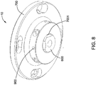
- FIG. 8 shows a schematic view of a forging device 10 for additive manufacturing according to one embodiment of the present invention.
- the forging device of the present invention may comprise the forging head as shown in FIGS. 1-7 of the embodiments of the present disclosure.
- the forging device 10 shown in Fig. 8 comprises the forging head 600 shown in FIG. 7 .
- the forging head 600 comprises a base portion 601, a forging portion 602 extending from one end of the base portion 601, and a through hole 603 which is formed through the base portion 601 and the forging portion 602.
- the forging portion 602 is configured for forging a cladding layer during formation of the cladding layer by additive manufacturing.
- the structure of the forging head 600 has been described in detail above and will not be described again herein.
- the forging device 10 also comprises a forging head fixing device 700 for fixing the forging head.
- the forging head fixing device 700 comprises a cavity 703 for receiving the forging head 600.
- the through hole 603 of the forging head 600 and the cavity 703 of the forging head fixing device 700 communicate with each other, and are configured to allow at least one of an energy beam and an additive material to pass through during formation of the cladding layer.
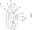
- FIG. 9 shows a schematic view of a forging head fixing device 700 according to one embodiment of the present invention.
- the forging head fixing device 700 comprises a circular base portion 701 and a cylindrical retaining portion 702 extending from one end of the base portion 701.
- the cavity 703 of the forging head fixing device 700 comprises a first cavity 7032 formed through the base portion 701 and a second cavity 7031 formed through the retaining portion 702.
- the aperture of the first cavity 7032 is smaller than the aperture of the second cavity 7031, thus the forging head fixing device 700 further comprises a resisting portion 704 formed on the top of the second cavity 7031.
- the retaining portion 702 is further provided with a receiving hole 708 for receiving the fastener 900 for fixing the forging head to the forging head fixing device.
- the fastener 900 is held under the step portion 605 of the forging head 600 to hold the forging head 600 stable inside the forging head fixing device 700.
- the fastener 900 can be a fixing pin or a nail.
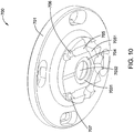
- FIG. 10 is a schematic view showing a portion of the forging head fixing device shown in FIG. 9 .
- the retaining portion 702 is internally provided with a channel 705 for circulating a coolant to cool the forging head.
- FIG. 10 is a schematic view showing the structure of the inner channel 705 of the forging head fixing device 700 according to an embodiment of the present invention.
- the forging head fixing device 700 is configured by providing a plurality of straight channels 7051 formed through the retaining portion 702 on the cylindrical retaining portion 702.
- the forging head fixing device 700 is provided with four straight channels 7051, and the four straight channels 7051 are sequentially connected to form a channel 705 for circulating a coolant.
- a plurality of openings are formed in the retaining portion of the forging head fixing device 700, except that the inlet 706 of the coolant and the outlet 707 of the coolant are retained, and other straight channels 7051 are formed; the openings formed during the process are sealed by brazing or other suitable sealing methods.
- the coolant can be circulated through the inlet 706 of the coolant and the outlet 707 of the coolant in the inner channel 705 of the retaining portion 702, thereby effectively cooling the forging head, while the service life of the forging head can also be prolonged.
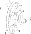
- FIG. 11 it shows a schematic view of a forging head fixing device 800 according to one embodiment of the present invention.
- the forging head fixing device 800 comprises a circular base portion 801 and a cylindrical retaining portion 802 extending from one end of the base portion 801.
- the forging head fixing device 800 also comprises a cavity 803 that houses the forging head.
- the cavity 803 also comprises a first cavity 8032 formed through the base 801 and a second cavity 8031 formed through the retaining portion 802.
- the aperture of the first cavity 8032 is smaller than the aperture of the second cavity 8031, thus the forging head fixing device 800 further comprises a resisting portion 804 formed on the top of the second cavity 8031.
- the forging head When the forging head is housed in the second cavity 8031 of the forging head fixing device 800, the forging head abuts against the resisting portion 804 to prevent the forging head from shaking. At the same time, the fastener is also held under the step portion of the forging head, thereby holding the forging head stable in the forging head fixing device 800.
- FIG. 12 is a schematic view showing a portion of the forging head fixing device shown in FIG. 11 .
- the retaining portion 802 is internally provided with a channel 805 for circulating a coolant to cool the forging head.
- FIG. 12 is a schematic view showing the structure of the inner channel 805 of the forging head fixing device 800 according to an embodiment of the present invention.
- the inner channel 805 is a circular channel integrally formed inside the retaining portion 802, and comprises an inlet 806 of a coolant and an outlet 807 of a coolant, such that the coolant can be cycled within the inner channel 805 of the retaining portion 802, thereby effectively cooling the forging head, while the service life of the forging head can be prolonged.
- the inner channel 805 of the forging head fixing device 800 shown in FIG. 12 is integrally formed inside the retaining portion 802, which simplifies the manufacturing process.
- FIG. 13 shows a schematic view of an additive manufacturing system 1 according to one embodiment of the present invention.
- the additive manufacturing system 1 comprises an energy source device 11 and a forging device 10.
- the energy source device 11 comprises an energy source for emitting an energy beam 111 to the substrate 14.
- the forging device 10 is configured to follow the energy beam 111, thereby forming a trajectory movement of the cladding layer during the formation of the cladding layer of the energy source device 11, for real-time forging of the cladding layer.
- the additive manufacturing system 1 further comprises a feeding device 13 that may comprise a feed nozzle 131.
- the feeding device 13 may also comprise feeding mechanisms of other shapes.
- the feeding device 13 can add an additive material 19 to the surface 141 of the substrate 14.
- the feeding device 13 generally comprises a hollow structure that allows the energy beam 111 to pass through.
- the first energy beam 111 may be in contact with an additive material added to the surface 141 of the substrate 14, whereby the additive material may be melted on the surface 141 of the substrate 14 to form the cladding layer 15.
- the additive manufacturing system 1 further comprises a coupling structure 12 disposed between the energy source device 11 and the feeding device 13, enabling the energy source device 11 and the feeding device 13 to be linked.
- the forging device 10 is disposed at the bottom of the feeding device 13.
- the forging head fixing device 700 is coupled to the feeding device, and the forging head 600 is secured under the forging head fixing device 700.
- the additive material 19 can be simultaneously passed through the cavity of the forging head fixing device 700 and the through hole of the forging head, while at the same time, the energy beam 111 of the energy source device 11 can be passed through, while coaxial powder feeding and coaxial in-situ forging can be realized.
- the additive material may be a powder or a filament.
- the additive material may be metal powder, alloy powder, super alloy powder, composite powder, metal filament, alloy filament, super alloy filament, and composite filament.
- the additive material may be added to the surface of the substrate by a feeding device through coaxial feeding, coaxial wire feeding, off-axis powder feeding, and off-axis wire feeding.
- the additive material may comprise a nickel based alloy powder.
- the forging device 10 may simultaneously forge at least a portion of the cladding layer 15.
- the forging head 600 can be moved up and down in the vertical direction. In the process of forming the cladding layer 15, the forging head 600 may be in contact with the surface of the cladding layer 15, thereby hammering, peening, or pressing a portion of the cladding layer 15, thus forging the portion of the cladding layer 14.
- the forging head 600 may move along a trajectory forming the cladding layer 15, which is in the same direction as the movement of the energy beam 111, for real-time forging of the cladding layer 15 during the formation of the cladding layer 15.
- a trajectory forming the cladding layer 15 which is in the same direction as the movement of the energy beam 111, for real-time forging of the cladding layer 15 during the formation of the cladding layer 15.
- the microstructure of the final cladding layer can also be altered, such as to promote recrystallization of the cladding layer material and formation of fine equiaxed crystal structures.
- the additive manufacturing system 1 further comprises a cooling device 16 which can provide a circulating coolant to the forging head fixing device 700 and can be used to continuously cool the forging head 600 to prolong the service life of the cooling head.
- a cooling device 16 which can provide a circulating coolant to the forging head fixing device 700 and can be used to continuously cool the forging head 600 to prolong the service life of the cooling head.
- the additive manufacturing system 1 of the present embodiment can realize coaxial in-situ forging in the additive manufacturing process; it can effectively improve the efficiency of the additive manufacturing system, and can also eliminate defects such as holes, slip planes and micro fractures in the cladding layer, thereby increasing the density of the final formed part.
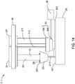
- FIG. 14 is a schematic diagram of an additive manufacturing system 2 according to one embodiment of the present invention.
- the additive manufacturing system 2 comprises an energy source device 21 and a forging mechanism 27.
- the energy source device 21 is configured to emit a first energy beam 211 and a second energy beam 212 to the substrate 24.
- the energy source device 21 can move the first energy beam 211 and the second energy beam 212 along a surface 231 of the substrate 24.
- the energy source device 11 comprises an energy source, while the first energy beam 211 and the second energy beam 212 are both provided by the energy source.
- the first energy beam 211 and the second energy beam 212 can be moved relative to the substrate 24, the substrate 24 being stationary.
- the energy source device is stationary.
- the first energy beam and the second energy beam emitted by the energy source device are also stationary.
- the substrate is movable relative to the first energy beam and the second energy beam along a trajectory of the first energy beam forming a cladding layer.
- the first energy beam, the second energy beam, and the substrate can simultaneously move along a trajectory of the first energy beam forming a cladding layer. The first energy beam and the second energy beam are move relative to the substrate.
- the additive manufacturing system 2 further comprises a feeding device 23.
- the additive manufacturing system 2 further comprises a coupling device 22 for connecting the feeding device 23 and the energy source device 21, allowing the feeding device 23 and the energy source device 21 to interlock.
- the feeding device 23 also moves together.
- the feeding device 23 comprises a feed nozzle 231.
- the feeding device 23 may also comprise other forms of feeding mechanisms, such as a powder feeder, a wire feeder, and so on.
- the feeding device 23 can add an additive material 29 to the surface 141 of the substrate 14.
- the feeding device 23 generally comprises a hollow structure that allows the first energy beam 211 to pass through.
- the first energy beam 211 may add to the additive material 29 of the substrate 24 through melting to form the cladding layer on the surface 241 of the substrate 24.
- the forging mechanism 27 comprises a fixing portion 271 and a forging device 20 connected to the fixing portion 271.
- the forging device 20 comprises a forging head fixing device 700 and a forging head 600 housed and secured at a lower end of the forging head fixing device 700.
- the second energy beam 212 emitted by the energy source 21 is adjacent to the forging device 27 and can pass through the cavity of the forging head fixing device 700 and the through hole of the forging head 600, thereby heating the cladding layer area forged by the forging head; it allows the cladding layer area forged by the forging head 60 to be always maintained within a suitable temperature range, which can reduce the damage to the forging head and prolong the service life of the forging head.
- the additive manufacturing system 2 further comprises a cooling device 26, providing a circulating coolant to the forging head fixing device 700 for continuously cooling the forging head to avoid excessive temperature of the forging head used for additive manufacturing, which may be prolonged The service life of the forging head.
- the additive manufacturing system 2 of the embodiment shown in FIG. 14 and the additive manufacturing system shown in FIG. 13 operate similarly, and will not be described again herein.
- the main difference between the additive manufacturing system 2 of the present embodiment and the additive manufacturing system 1 of FIG. 13 is that the energy source 21 can emit a first energy beam 211 and a second energy beam 212, the first energy beam 211 is used to add additive material 29 to the substrate through melting, the second energy beam 212 can pass through the cavity of the forging head fixing device of the forging device 20 and the through hole of the forging head, thereby heating the cladding layer area forged by the forging head 600 during the forging process, thus reducing the damages to the forging head.
- the additive manufacturing system further comprises a coupling mechanism 28 for connecting the energy source device 21 and the forging mechanism 27, to realize effect linkage between the energy source device 21 and the forging mechanism 27.
- the additive manufacturing system 2 can realize real-time forging of the cladding layer by using a forging mechanism during the process of forming a cladding layer through additive manufacturing, and can eliminate defects such as holes, slip planes and micro fractures in the cladding layer, thereby increasing the density of the final formed part; at the same time, the second energy beam is also used to heat the forged cladding layer area to reduce the damage to the forging head, while the cooling device is simultaneously used to cool the forging head, thus prolonging the service life of the forging head.
Landscapes
- Engineering & Computer Science (AREA)
- Mechanical Engineering (AREA)
- Manufacturing & Machinery (AREA)
- Chemical & Material Sciences (AREA)
- Materials Engineering (AREA)
- Physics & Mathematics (AREA)
- Optics & Photonics (AREA)
- Plasma & Fusion (AREA)
- Organic Chemistry (AREA)
- Metallurgy (AREA)
- Chemical Kinetics & Catalysis (AREA)
- Forging (AREA)
- Powder Metallurgy (AREA)
Description
- The present invention relates to a forging device suitable for additive manufacturing, and an additive manufacturing system using the forging device.
- Additive manufacturing technology is a rapidly evolving emerging technology for material processing. At present, the mainstream additive manufacturing usually achieves metallurgical bonding of metal materials through the "melting-solidification" method, which is characterized by using a high-energy beam such as a laser beam, an electron beam or an arc beam as a heat source to melt the synchronously fed metal material, such as metal powder, metal wire, and so on, which arc stacked in layers, whereby parts are manufactured by surfacing, and the internal microstructure of the obtained parts is a solidified structure.
- Compared with the conventional forged structure, the solidified structure obtained by the above-mentioned "melting-solidification" method produces crystals that are very coarse with obvious directionality, therefore in a general sense, it is difficult to achieve comprehensive performance comparable to that of a forged material. In order to improve the mechanical properties of the obtained parts and reduce internal defects, a method of combining the molten deposition additive with thermomechanical processing has been gradually developed, that is, material deposition and metallurgical bonding are achieved by melting-solidification, thereafter rolling, shock processing and other treatments are used to refine the grains and improve internal quality.
- Although the method of melting combined with forging can improve the internal quality as well as enhance performance to some extent, in this composite machining method, it is generally carried out under high temperature processing conditions. Thus, the forging head of the forging device (for example, the impacting member) needs to be forged under very high temperature and stress, which easily causes damage or scrapping of the forging head, affecting the efficiency of the entire additive manufacturing combined with the forging composite machining process.
- Therefore, it is necessary to provide a novel forging head and forging device which can be applied to an additive manufacturing system and which can solve at least one of the above-mentioned technical problems.
- A forging head for additive manufacturing, comprising: a base portion and a forging portion. The forging portion extends from the base portion for forging a cladding layer during formation of the cladding layer by additive manufacturing; the forging head further comprising a through hole which is formed through the base portion and the forging portion, for at least one of an energy bean and an additive material to pass through during formation of the cladding layer.
- A forging device for additive manufacturing, comprising: a forging head and a forging head fixing device. The forging head comprises a base portion, a forging portion extending from the base portion, and a through hole formed through the base portion and the forging portion. The forging portion is configured for forging a cladding layer during formation of the cladding layer by additive manufacturing. The forging head fixing device comprising a cavity, for receiving the forging head.
- The through hole and the cavity communicate with each other, and are configured to allow at least one of an energy beam and an additive material to pass through during formation of the cladding layer.
- An additive manufacturing system, comprising: an energy source and a forging device. The energy source is configured to provide an energy beam, for fusing at least a portion of a material added to a surface of the substrate for forming a cladding layer on the substrate or heating the cladding layer.
- The forging device comprises a forging head, for forging the cladding layer during formation of the cladding layer by additive manufacturing. The forging head comprises a base portion, a forging portion and a through hole formed through the base portion and the forging portion. The through hole is configured to allow at least one of an energy beam and an additive material to pass through during formation of the cladding layer.
-
CN 107 287 588 A discloses a forging apparatus for a laser cladding system. - These and other features, aspects and advantages of the present invention will become better understood when the following detailed description is read with reference to the accompanying drawings, in which like reference numerals are used throughout the drawings to refer to like parts, where:
-
FIG. 1 is a perspective view of a forging head according to an embodiment of the present disclosure. -
FIG. 2 is a perspective view of a forging head according to an embodiment of the present disclosure. -
FIG. 3 is a perspective view of a forging head according to an embodiment of the present disclosure. -
FIG. 4 is a perspective view of a forging head according to an embodiment of the present disclosure. -
FIG. 5 is a cross-sectional view of the forging head ofFIG. 4 taken along line A-A. -
FIG. 6 is a perspective view of a forging head according to an embodiment of the present disclosure. -
FIG. 7 is a perspective view of a forging head according to an embodiment of the present disclosure. -
FIG. 8 is a perspective view of a forging device according to an embodiment of the present invention. -
FIG. 9 is a perspective view showing the forging head fixing device of the forging device shown inFIG. 8 . -
FIG. 10 is a schematic view showing the forging head fixing device inFIG. 9 after a part of its fixing portion is cut away. -
FIG. 11 is a perspective view of a forging head fixing device of a forging device according to an embodiment of the present invention. -
FIG. 12 is a schematic view showing the forging head fixing device inFIG. 11 after a part of its fixing portion is cut away. -
FIG. 13 is a schematic of an additive manufacturing system according to an embodiment of the present invention. -
FIG. 14 is a schematic of an additive manufacturing system according to an embodiment of the present invention. - Unless otherwise defined, technical terms or scientific terms used in this specification and claims are to be understood as the ordinary meaning of the ordinary skill in the art. "First", "second", and similar words used herein do not denote any order, quantity, or importance, but are merely intended to distinguish between different constituents. The terms "one", "a" and similar words are not meant to be limiting, but rather denote the presence of at least one. The approximate language used herein can be used for quantitative expressions, indicating that there is a certain amount of variation that can be allowed without changing the basic functions. Thus, numerical values that are corrected by language such as "approximately" or "about" are not limited to the exact value itself. Similarly, the terms "one", "a", and similar words are not meant to be limiting, but rather denote the presence of at least one. "Comprising", "consisting", and similar words mean that elements or articles appearing before "comprising" or "consisting" include the elements or articles and their equivalent elements appearing behind "comprising" or "consisting", not excluding any other elements or articles. "Connected", "connection", "coupled", and similar words are not limited to a physical or mechanical connection, but may include direct or indirect electrical connections, thermal connections, thermally conductive connections, and thermally transmissive connections.
- The present invention relates to a forging device for additive manufacturing, and an additive manufacturing system using the forging device.
-
FIG. 1 shows a schematic view of a forginghead 100 according to an embodiment of the present disclosure. The forginghead 100 can be configured for additive manufacturing in combination with forging composite processes. The forginghead 100 comprises acylindrical base portion 101 and a forgingportion 102 at the bottom of thebase portion 101. Theforging portion 102 extends from the bottom of thebase portion 101 for forging a cladding layer during formation of the cladding layer by additive manufacturing. The forginghead 100 further comprises a throughhole 103 formed through thebase portion 101 and the forgingportion 102. Thethrough hole 103 has a straight cylindrical shape, and is configured to allow at least one of an energy beam and an additive material of the additive manufacturing system to pass through during formation of the cladding layer. - The forging
portion 102 comprises a substantiallyflat forging surface 104 for contacting the cladding layer. The forgingportion 102 is located on one side of the throughhole 103. The forginghead 100 also forms a plurality ofgrooves 106 on thebase portion 101 by cutting a portion of thecylindrical base portion 101 in a direction toward the top end of thebase portion 101 to form a plurality ofstep portions 105 adjacent to a top end thereof. Thestep portion 105 can be fixed to the forging head fixing device by mating with the fastener. - The forging
head 100 can move along the trajectory of the additive manufacturing system to form the cladding layer. The forgingportion 102 can forge the cladding layer in real time during the formation of the cladding layer, thereby achieving peening on the cladding layer, and eliminating defects such as holes, slip planes, and micro fractures in the cladding layer, thereby increasing the density of the final formed part. In addition, the microstructure of the final cladding layer can also be altered, such as to promote recrystallization of the cladding layer material and formation of fine equiaxed crystal structures. In the present embodiment, the forgingsurface 104 of the forgingportion 102 of the forginghead 100 is flat, which can increase the contact area with the cladding layer and improve the forging efficiency of the forginghead 100. -
FIG. 2 shows a schematic view of a forginghead 200 according to an embodiment of the present disclosure. The forginghead 200 can be configured for additive manufacturing in combination with forging composite processes. The forginghead 200 shown inFIG. 2 is substantially identical in construction to the forginghead 100 of the embodiment shown inFIG. 1 , which also comprises acylindrical base portion 201 and a forgingportion 202 at the bottom of thebase portion 201. The forgingportion 202 extends from the bottom of thebase portion 201 for forging a cladding layer during formation of the cladding layer by additive manufacturing. The forginghead 200 also comprises a throughhole 203 formed through thebase portion 201 and the forgingportion 202. The throughhole 203 has a straight cylindrical shape, and is configured to allow at least one of an energy beam and an additive material of the additive manufacturing system to pass through during formation of the cladding layer. - The forging
portion 202 comprises a substantially flat forgingsurface 204 for contacting the cladding layer. The forgingportion 202 is also located on one side of the throughhole 203. The forginghead 200 also forms a plurality ofgrooves 206 on thebase portion 201 by cutting a portion of thecylindrical base portion 201 in a direction toward the top end of thebase portion 201 to form a plurality ofstep portions 205 adjacent to a top end thereof. Thestep portion 205 can be fixed to the forging head fixing device by mating with the fastener. - The forging
head 200 is substantially identical in construction to the forginghead 100 of the embodiment ofFIG. 1 , which can move along the trajectory of the additive manufacturing system to form the cladding layer. The forgingportion 202 can also forge the cladding layer in real time during the formation of the cladding layer, thereby achieving peening on the cladding layer, and eliminating defects such as holes, slip planes, and micro fractures in the cladding layer, thereby increasing the density of the final formed part. In addition, the microstructure of the final cladding layer can also be altered, such as to promote recrystallization of the cladding layer material and formation of fine equiaxed crystal structures. In the present embodiment, the main difference between the forginghead 200 and the forginghead 100 shown in the embodiment ofFIG. 1 is that the forgingsurface 204 of the forgingportion 202 of the forginghead 200 is curved, which can increase the forged cladding layer; the stress in contact with the cladding layer is mainly applied to materials with high yield strength. -
FIG. 3 shows a schematic view of a forginghead 300 according to an embodiment of the present disclosure. The forginghead 300 can also be used in additive manufacturing in combination with forging composite processes. The forginghead 300 shown inFIG. 3 is substantially identical to the forging head construction of the embodiment shown inFIGS. 1 and2 , and also comprises acylindrical base portion 301 and a forgingportion 302 at the bottom of thebase portion 301. The forgingportion 302 extends from the bottom of thebase portion 301 for forging a cladding layer during formation of the cladding layer by additive manufacturing. The forginghead 300 also comprises a throughhole 303 formed through thebase portion 301 and the forgingportion 302. The throughhole 303 has a straight cylindrical shape, and is configured to allow at least one of an energy beam and an additive material of the additive manufacturing system to pass through during formation of the cladding layer. - The forging
portion 302 comprises a substantially flat forgingsurface 304 for contacting the cladding layer. The forginghead 300 also forms a plurality ofgrooves 306 on thebase portion 301 by cutting a portion of thecylindrical base portion 301 in a direction toward the top end of thebase portion 301 to form a plurality ofstep portions 305 adjacent to a top end thereof. Thestep portion 305 can also be fixed to the forging head fixing device by mating with the fastener. - The forging
head 300 is substantially identical in structure to the forging head of the embodiments ofFIG. 1 andFIG. 2 , which can move along the trajectory of the additive manufacturing system to form the cladding layer. The forgingportion 302 can also forge the cladding layer in real time during the formation of the cladding layer, thereby achieving peening on the cladding layer, and eliminating defects such as holes, slip planes, and micro fractures in the cladding layer, thereby increasing the density of the final formed part. In addition, the microstructure of the final cladding layer can also be altered, such as to promote recrystallization of the cladding layer material and formation of fine equiaxed crystal structures. - In the embodiment shown in
FIG. 3 , the main difference between the forginghead 300 and the forginghead 100 shown in the embodiment ofFIG. 1 is that the forgingportion 302 of the forginghead 300 is symmetrically disposed on both sides of the throughhole 303. Thereby, the forginghead 300 can forge the cladding layer in real time during the reciprocating movement along the trajectory of the additive manufacturing system to form the cladding layer, and the forging efficiency of the forginghead 300 can be effectively improved. -
FIG. 4 shows a schematic view of a forginghead 400 according to an embodiment of the present disclosure. The forginghead 400 can also be used in additive manufacturing in combination with forging composite processes. The forginghead 400 shown inFIG. 4 is substantially identical in construction to the forging head of the embodiment shown inFIGS. 1 to 3 , which also comprises acylindrical base portion 401 and a forgingportion 402 at the bottom of thebase portion 401. The forgingportion 402 extends from the bottom of thebase portion 401 for forging a cladding layer during formation of the cladding layer by additive manufacturing. The forginghead 400 also comprises a throughhole 403 formed through thebase portion 401 and the forgingportion 402. The throughhole 403 is configured to allow at least one of an energy beam and an additive material of the additive manufacturing system to pass through during formation of the cladding layer. - The forging
portion 402 comprises a substantially flat forgingsurface 404 for contacting the cladding layer. The forginghead 400 also forms a plurality ofgrooves 406 on thebase portion 401 by cutting a portion of thecylindrical base portion 401 in a direction toward the top end of thebase portion 401 to form a plurality ofstep portions 405 adjacent to a top end thereof. Thestep portion 405 is also capable of fixing the forginghead 400 to the forging head fixing device by mating with the fastener. - The forging
head 400 is substantially identical in construction to the forging head of the embodiment shown inFIGS. 1-3 , which can move along the trajectory of the additive manufacturing system to form the cladding layer. The forgingportion 402 can also forge the cladding layer in real time during the formation of the cladding layer, thereby achieving peening on the cladding layer, and eliminating defects such as holes, slip planes, and micro fractures in the cladding layer, thereby increasing the density of the final formed part. In addition, the microstructure of the final cladding layer can also be altered, such as to promote recrystallization of the cladding layer material and formation of fine equiaxed crystal structures. - In the embodiment shown in
FIG. 4 , the main difference between the forginghead 400 and the forginghead 100 shown in the embodiment ofFIG. 1 is that the forgingportion 402 of the forginghead 400 is symmetrically disposed on both sides of the throughhole 403, while the forgingsurface 404 of the forgingportion 402 configured to come into contact with the cladding layer is curved. - Thereby, the forging
head 400 can forge the cladding layer in real time during the reciprocating movement along the trajectory of the additive manufacturing system to form the cladding layer, and the forging efficiency of the forginghead 400 can be effectively improved; at the same time, the curved forgingsurface 404 can increase the stress in contact with the cladding layer when the forging head forges the cladding layer, which is mainly suitable for materials with high yield strength. In combination withFIG. 5 , it shows that the throughhole 403 of the forginghead 400 has a structure that is larger at the top and smaller at the bottom, with the longitudinal cross section of the throughhole 403 having an inverted trapezoidal structure. Thereby, the throughhole 403 focuses of the additive material of the additive manufacturing system to avoid interference, while on the other hand, it is advantageous for increasing the forging portion of the forginghead 400, such that the forging efficiency of the forging head can be correspondingly improved. -
FIG. 6 shows a schematic view of a forginghead 500 according to an embodiment of the present disclosure. The forginghead 500 can also be used in additive manufacturing in combination with forging composite processes. The forginghead 500 shown inFIG. 6 is substantially identical in construction to the forging head of the embodiment shown inFIGS. 1 to 5 , which also comprises acylindrical base portion 501 and a forgingportion 502 at the bottom of thebase portion 501. The forgingportion 502 extends from the bottom of thebase portion 501 for forging a cladding layer during formation of the cladding layer by additive manufacturing. The forginghead 500 also comprises a throughhole 503 formed through thebase portion 501 and the forgingportion 502. The throughhole 503 is configured to allow at least one of an energy beam and an additive material of the additive manufacturing system to pass through during formation of the cladding layer. - The forging
portion 502 comprises a substantially flat forgingsurface 504 for contacting the cladding layer. The forginghead 500 also forms a plurality ofgrooves 506 on thebase portion 501 by cutting a portion of thecylindrical base portion 501 in a direction toward the top end of thebase portion 501 to form a plurality ofstep portions 505 adjacent to a top end thereof. Thestep portion 505 is also capable of fixing the forginghead 500 to the forging head fixing device by mating with the fastener. - The forging
head 500 is substantially identical in construction to the forging head of the embodiment ofFIGS. 1-5 , which can move along the trajectory of the additive manufacturing system to form the cladding layer. The forgingportion 502 can also forge the cladding layer in real time during the formation of the cladding layer, thereby achieving peening on the cladding layer, and eliminating defects such as holes, slip planes, and micro fractures in the cladding layer, thereby increasing the density of the final formed part. In addition, the microstructure of the final cladding layer can also be altered, such as to promote recrystallization of the cladding layer material and formation of fine equiaxed crystal structures. - In the embodiment shown in
FIG. 6 , the main difference between the forginghead 500 and the forginghead 100 shown in the embodiment ofFIG. 1 is that the forgingportion 502 of the forginghead 500 is formed by integrally extending from the bottom of thebase portion 501 which also surrounds the throughhole 503. Moreover, the entire forgingsurface 504 of the forgingportion 502 in contact with the cladding layer is flat. Thereby, the forginghead 500 can forge the cladding layer in real time during the reciprocating movement along the trajectory of the additive manufacturing system to form the cladding layer or along the more complicated additive manufacturing cladding path; it can effectively improve the forging efficiency of the forginghead 500, while the entire flat forgingsurface 504 can increase the area of contact with the cladding layer as the forging head is forging the cladding layer, which can also effectively improve the forging efficiency of the forging head. -
FIG. 7 shows a schematic view of a forginghead 600 according to an embodiment of the present disclosure. The forginghead 600 can also be used in additive manufacturing in combination with forging composite processes. The forginghead 600 shown inFIG. 7 is substantially identical in construction to the forging head of the embodiment shown inFIGS. 1 to 6 , which also comprises acylindrical base portion 601 and a forgingportion 602 at the bottom of thebase portion 601. The forgingportion 602 extends from the bottom of thebase portion 601 for forging a cladding layer during formation of the cladding layer by additive manufacturing. The forginghead 600 also comprises a throughhole 603 formed through thebase portion 601 and the forgingportion 602. The throughhole 603 is configured to allow at least one of an energy beam and an additive material of the additive manufacturing system to pass through during formation of the cladding layer. - The forging
portion 602 comprises a substantially flat forgingsurface 604 for contacting the cladding layer. The forginghead 600 also forms a plurality ofgrooves 606 on thebase portion 601 by cutting a portion of thecylindrical base portion 601 in a direction toward the top end of thebase portion 601 to form a plurality ofstep portions 605 adjacent to a top end thereof. Thestep portion 605 is also capable of fixing the forginghead 600 to the forging head fixing device by mating with the fastener. - The forging
head 600 is substantially identical in construction to the forging head of the embodiment ofFIGS. 1-6 , which can move along the trajectory of the additive manufacturing system to form the cladding layer. The forgingportion 602 can also forge the cladding layer in real time during the formation of the cladding layer, thereby achieving peening on the cladding layer, and eliminating defects such as holes, slip planes, and micro fractures in the cladding layer, thereby increasing the density of the final formed part. In addition, the microstructure of the final cladding layer can also be altered, such as to promote recrystallization of the cladding layer material and formation of fine equiaxed crystal structures. - In the embodiment shown in
FIG. 7 , the main difference between the forginghead 600 and the forginghead 100 shown in the embodiment ofFIG. 1 is that the forgingportion 602 of the forginghead 600 is formed by integrally extending from the bottom of thebase portion 601 which also surrounds the throughhole 603. Also, the entire forgingsurface 504 of the forgingportion 602 for contact with the cladding layer is curved. Thereby, the forginghead 600 can forge the cladding layer in real time during the reciprocating movement along the trajectory of the additive manufacturing system to form the cladding layer or along the more complicated additive manufacturing cladding path; it can effectively improve the forging efficiency of the forginghead 600, while the curved forgingsurface 604 can increase the stress in contact with the cladding layer as the forging head is forging the cladding layer, which is mainly suitable for materials with high yield strength. - The forging head of the present disclosure is made of an alloy material which mainly comprises an alloy material having a hardness of greater than 30 Rockwell C hardness. In some embodiments, the alloy material comprises a tungsten carbide based cemented carbide. The tungsten carbide based cemented carbide contains cobalt, with a percentage of the cobalt (by weight) less than 30%. In some embodiments, the tungsten carbide based cemented carbide contains cobalt, with a percentage of cobalt (by weight) around 20% to 25%. Thus, the forging head can be guaranteed to have better toughness and hardness. In some embodiments, the alloy material comprises a nickel based alloy which contains tungsten in an amount greater than 10% (by weight). The nickel based alloy comprises molybdenum and more than 10% tungsten (by weight), with the molybdenum and tungsten present in an amount greater than 15% (by weight). Thus, the forging head can also be guaranteed to have better toughness and hardness. The material of the forging head is mainly selected according to the additive material manufactured which is required for forging.
-
FIG. 8 shows a schematic view of a forgingdevice 10 for additive manufacturing according to one embodiment of the present invention. The forging device of the present invention may comprise the forging head as shown inFIGS. 1-7 of the embodiments of the present disclosure. The forgingdevice 10 shown inFig. 8 comprises the forginghead 600 shown inFIG. 7 . The forginghead 600 comprises abase portion 601, a forgingportion 602 extending from one end of thebase portion 601, and a throughhole 603 which is formed through thebase portion 601 and the forgingportion 602. The forgingportion 602 is configured for forging a cladding layer during formation of the cladding layer by additive manufacturing. The structure of the forginghead 600 has been described in detail above and will not be described again herein. - The forging
device 10 also comprises a forginghead fixing device 700 for fixing the forging head. The forginghead fixing device 700 comprises acavity 703 for receiving the forginghead 600. The throughhole 603 of the forginghead 600 and thecavity 703 of the forginghead fixing device 700 communicate with each other, and are configured to allow at least one of an energy beam and an additive material to pass through during formation of the cladding layer. - Refer to
FIG. 9 , which shows a schematic view of a forginghead fixing device 700 according to one embodiment of the present invention. The forginghead fixing device 700 comprises acircular base portion 701 and acylindrical retaining portion 702 extending from one end of thebase portion 701. Thecavity 703 of the forginghead fixing device 700 comprises afirst cavity 7032 formed through thebase portion 701 and asecond cavity 7031 formed through the retainingportion 702. The aperture of thefirst cavity 7032 is smaller than the aperture of thesecond cavity 7031, thus the forginghead fixing device 700 further comprises a resistingportion 704 formed on the top of thesecond cavity 7031. When the forging head is housed in thesecond cavity 7031 of the forginghead fixing device 700, the forging head abuts against the resistingportion 704 to prevent the forging head from shaking. - The retaining
portion 702 is further provided with a receivinghole 708 for receiving thefastener 900 for fixing the forging head to the forging head fixing device. Thefastener 900 is held under thestep portion 605 of the forginghead 600 to hold the forginghead 600 stable inside the forginghead fixing device 700. In some embodiments, thefastener 900 can be a fixing pin or a nail. - By combining
FIG. 9 andFIG. 10, FIG. 10 is a schematic view showing a portion of the forging head fixing device shown inFIG. 9 . The retainingportion 702 is internally provided with achannel 705 for circulating a coolant to cool the forging head.FIG. 10 is a schematic view showing the structure of theinner channel 705 of the forginghead fixing device 700 according to an embodiment of the present invention. The forginghead fixing device 700 is configured by providing a plurality ofstraight channels 7051 formed through the retainingportion 702 on thecylindrical retaining portion 702. In the present embodiment, the forginghead fixing device 700 is provided with fourstraight channels 7051, and the fourstraight channels 7051 are sequentially connected to form achannel 705 for circulating a coolant. Since fourstraight channels 7051 are to be formed, a plurality of openings are formed in the retaining portion of the forginghead fixing device 700, except that theinlet 706 of the coolant and theoutlet 707 of the coolant are retained, and otherstraight channels 7051 are formed; the openings formed during the process are sealed by brazing or other suitable sealing methods. The coolant can be circulated through theinlet 706 of the coolant and theoutlet 707 of the coolant in theinner channel 705 of the retainingportion 702, thereby effectively cooling the forging head, while the service life of the forging head can also be prolonged. - Referring to
FIG. 11 , it shows a schematic view of a forginghead fixing device 800 according to one embodiment of the present invention. The forginghead fixing device 800 comprises acircular base portion 801 and acylindrical retaining portion 802 extending from one end of thebase portion 801. The forginghead fixing device 800 also comprises acavity 803 that houses the forging head. Thecavity 803 also comprises afirst cavity 8032 formed through thebase 801 and asecond cavity 8031 formed through the retainingportion 802. The aperture of thefirst cavity 8032 is smaller than the aperture of thesecond cavity 8031, thus the forginghead fixing device 800 further comprises a resistingportion 804 formed on the top of thesecond cavity 8031. When the forging head is housed in thesecond cavity 8031 of the forginghead fixing device 800, the forging head abuts against the resistingportion 804 to prevent the forging head from shaking. At the same time, the fastener is also held under the step portion of the forging head, thereby holding the forging head stable in the forginghead fixing device 800. - By combining
FIG. 11 andFIG. 12, FIG. 12 is a schematic view showing a portion of the forging head fixing device shown inFIG. 11 . The retainingportion 802 is internally provided with achannel 805 for circulating a coolant to cool the forging head.FIG. 12 is a schematic view showing the structure of theinner channel 805 of the forginghead fixing device 800 according to an embodiment of the present invention. Theinner channel 805 is a circular channel integrally formed inside the retainingportion 802, and comprises aninlet 806 of a coolant and anoutlet 807 of a coolant, such that the coolant can be cycled within theinner channel 805 of the retainingportion 802, thereby effectively cooling the forging head, while the service life of the forging head can be prolonged. Theinner channel 805 of the forginghead fixing device 800 shown inFIG. 12 is integrally formed inside the retainingportion 802, which simplifies the manufacturing process. -
FIG. 13 shows a schematic view of anadditive manufacturing system 1 according to one embodiment of the present invention. Theadditive manufacturing system 1 comprises anenergy source device 11 and a forgingdevice 10. Theenergy source device 11 comprises an energy source for emitting an energy beam 111 to thesubstrate 14. The forgingdevice 10 is configured to follow the energy beam 111, thereby forming a trajectory movement of the cladding layer during the formation of the cladding layer of theenergy source device 11, for real-time forging of the cladding layer. - In some embodiments, the
additive manufacturing system 1 further comprises afeeding device 13 that may comprise afeed nozzle 131. Of course, thefeeding device 13 may also comprise feeding mechanisms of other shapes. Thefeeding device 13 can add anadditive material 19 to thesurface 141 of thesubstrate 14. Thefeeding device 13 generally comprises a hollow structure that allows the energy beam 111 to pass through. The first energy beam 111 may be in contact with an additive material added to thesurface 141 of thesubstrate 14, whereby the additive material may be melted on thesurface 141 of thesubstrate 14 to form thecladding layer 15. - The
additive manufacturing system 1 further comprises acoupling structure 12 disposed between theenergy source device 11 and thefeeding device 13, enabling theenergy source device 11 and thefeeding device 13 to be linked. The forgingdevice 10 is disposed at the bottom of thefeeding device 13. The forginghead fixing device 700 is coupled to the feeding device, and the forginghead 600 is secured under the forginghead fixing device 700. Thereby, theadditive material 19 can be simultaneously passed through the cavity of the forginghead fixing device 700 and the through hole of the forging head, while at the same time, the energy beam 111 of theenergy source device 11 can be passed through, while coaxial powder feeding and coaxial in-situ forging can be realized. - In some embodiments of the present invention, the additive material may be a powder or a filament. The additive material may be metal powder, alloy powder, super alloy powder, composite powder, metal filament, alloy filament, super alloy filament, and composite filament. The additive material may be added to the surface of the substrate by a feeding device through coaxial feeding, coaxial wire feeding, off-axis powder feeding, and off-axis wire feeding. In some embodiments of the present invention, the additive material may comprise a nickel based alloy powder.
- While the
energy source device 11 is emitting the first energy beam 111 on the surface of thesubstrate 14, the forgingdevice 10 may simultaneously forge at least a portion of thecladding layer 15. The forginghead 600 can be moved up and down in the vertical direction. In the process of forming thecladding layer 15, the forginghead 600 may be in contact with the surface of thecladding layer 15, thereby hammering, peening, or pressing a portion of thecladding layer 15, thus forging the portion of thecladding layer 14. - The forging
head 600 may move along a trajectory forming thecladding layer 15, which is in the same direction as the movement of the energy beam 111, for real-time forging of thecladding layer 15 during the formation of thecladding layer 15. Thus achieving peening on the cladding layer, and eliminating defects such as holes, slip planes, and micro fractures in thecladding layer 15, thereby increasing the density of the final formed part. In addition, the microstructure of the final cladding layer can also be altered, such as to promote recrystallization of the cladding layer material and formation of fine equiaxed crystal structures. - The
additive manufacturing system 1 further comprises acooling device 16 which can provide a circulating coolant to the forginghead fixing device 700 and can be used to continuously cool the forginghead 600 to prolong the service life of the cooling head. - The
additive manufacturing system 1 of the present embodiment can realize coaxial in-situ forging in the additive manufacturing process; it can effectively improve the efficiency of the additive manufacturing system, and can also eliminate defects such as holes, slip planes and micro fractures in the cladding layer, thereby increasing the density of the final formed part. - Please refer to
FIG. 14 , which is a schematic diagram of anadditive manufacturing system 2 according to one embodiment of the present invention. Theadditive manufacturing system 2 comprises anenergy source device 21 and a forgingmechanism 27. Theenergy source device 21 is configured to emit afirst energy beam 211 and asecond energy beam 212 to thesubstrate 24. - The
energy source device 21 can move thefirst energy beam 211 and thesecond energy beam 212 along asurface 231 of thesubstrate 24. In the present embodiment, theenergy source device 11 comprises an energy source, while thefirst energy beam 211 and thesecond energy beam 212 are both provided by the energy source. In the present embodiment, thefirst energy beam 211 and thesecond energy beam 212 can be moved relative to thesubstrate 24, thesubstrate 24 being stationary. - In some embodiments, the energy source device is stationary. Thus, the first energy beam and the second energy beam emitted by the energy source device are also stationary. The substrate is movable relative to the first energy beam and the second energy beam along a trajectory of the first energy beam forming a cladding layer. In some embodiments, the first energy beam, the second energy beam, and the substrate can simultaneously move along a trajectory of the first energy beam forming a cladding layer. The first energy beam and the second energy beam are move relative to the substrate.
- In some embodiments of the present invention, the
additive manufacturing system 2 further comprises afeeding device 23. Theadditive manufacturing system 2 further comprises acoupling device 22 for connecting thefeeding device 23 and theenergy source device 21, allowing thefeeding device 23 and theenergy source device 21 to interlock. When theenergy source device 21 is moved, thefeeding device 23 also moves together. Thefeeding device 23 comprises afeed nozzle 231. Of course, thefeeding device 23 may also comprise other forms of feeding mechanisms, such as a powder feeder, a wire feeder, and so on. Thefeeding device 23 can add anadditive material 29 to thesurface 141 of thesubstrate 14. Thefeeding device 23 generally comprises a hollow structure that allows thefirst energy beam 211 to pass through. Thefirst energy beam 211 may add to theadditive material 29 of thesubstrate 24 through melting to form the cladding layer on thesurface 241 of thesubstrate 24. - The forging
mechanism 27 comprises a fixingportion 271 and a forgingdevice 20 connected to the fixingportion 271. The forgingdevice 20 comprises a forginghead fixing device 700 and a forginghead 600 housed and secured at a lower end of the forginghead fixing device 700. Thesecond energy beam 212 emitted by theenergy source 21 is adjacent to the forgingdevice 27 and can pass through the cavity of the forginghead fixing device 700 and the through hole of the forginghead 600, thereby heating the cladding layer area forged by the forging head; it allows the cladding layer area forged by the forging head 60 to be always maintained within a suitable temperature range, which can reduce the damage to the forging head and prolong the service life of the forging head. - The
additive manufacturing system 2 further comprises acooling device 26, providing a circulating coolant to the forginghead fixing device 700 for continuously cooling the forging head to avoid excessive temperature of the forging head used for additive manufacturing, which may be prolonged The service life of the forging head. - The
additive manufacturing system 2 of the embodiment shown inFIG. 14 and the additive manufacturing system shown inFIG. 13 operate similarly, and will not be described again herein. The main difference between theadditive manufacturing system 2 of the present embodiment and theadditive manufacturing system 1 ofFIG. 13 is that theenergy source 21 can emit afirst energy beam 211 and asecond energy beam 212, thefirst energy beam 211 is used to addadditive material 29 to the substrate through melting, thesecond energy beam 212 can pass through the cavity of the forging head fixing device of the forgingdevice 20 and the through hole of the forging head, thereby heating the cladding layer area forged by the forginghead 600 during the forging process, thus reducing the damages to the forging head. The additive manufacturing system further comprises acoupling mechanism 28 for connecting theenergy source device 21 and the forgingmechanism 27, to realize effect linkage between theenergy source device 21 and the forgingmechanism 27. - The
additive manufacturing system 2 can realize real-time forging of the cladding layer by using a forging mechanism during the process of forming a cladding layer through additive manufacturing, and can eliminate defects such as holes, slip planes and micro fractures in the cladding layer, thereby increasing the density of the final formed part; at the same time, the second energy beam is also used to heat the forged cladding layer area to reduce the damage to the forging head, while the cooling device is simultaneously used to cool the forging head, thus prolonging the service life of the forging head. - The description uses specific embodiments to describe the present invention, including the best mode, and can help any person skilled in the art perform experimental operations. These operations include using any device and system and using any specific method. The patentable scope of the present invention is defined by the claims.
Claims (14)
- A forging device (10) for additive manufacturing, comprising:- a forging head (100, 200, 300, 400, 500, 600) for additive manufacturing, comprising:-- abase portion (101, 201, 301, 401, 501, 601);-- a forging portion (102, 202, 302, 402, 502, 602) extending from the base portion (101, 201, 301, 401, 501, 601), configured to forge a cladding layer (15, 25) during formation of the cladding layer (15, 25) by additive manufacturing; wherein-- a through hole (103, 203, 303, 403, 503, 603) is formed through the base portion (101, 201, 301, 401, 501, 601) and the forging portion (102, 202, 302, 402, 502, 602), configured to allow at least one of an energy beam (111, 211, 212) and an additive material (19, 29) to pass through during formation of the cladding layer (15, 25);- a forging head fixing device (700, 800) comprising a cavity (703, 803) configured to receive the forging head (100, 200, 300, 400, 500, 600); whereinthe through hole (103, 203, 303, 403, 503, 603) and the cavity (703, 803) communicate with each other, and are configured to allow at least one of an energy beam (111, 211, 212) and an additive material (19, 29) to pass through during formation of the cladding layer (15, 25).
- The forging device of claim 1, wherein the forging head fixing device (700, 800) comprises a main portion (701, 801) and a holding portion (702, 802) extending downward from one end of the main portion (701, 801), the cavity (703, 803) comprises a first cavity (7031, 8031) penetrating the main portion (701, 801) and a second cavity (7032, 8032) penetrating the holding portion (702, 802), and the base portion (101, 201, 301, 401, 501, 601) is retained within the second cavity (7032, 8032).
- The forging device of claim 2, wherein a channel (705, 805) is arranged in the interior of the holding portion (702, 802), configured to circulate a cooling liquid to cool the forging head (100, 200, 300, 400, 500, 600).
- The forging device of any one of the preceding claims, wherein the forging portion (102, 302, 502) comprises a substantially flat forging surface (104, 304, 504) configured to contact the cladding layer (15, 25).
- The forging device of any of claims 1 - 3, wherein the forging portion (202, 402, 602) comprises an arched forging surface (204, 404, 604) configured to contact the cladding layer (15, 25).
- The forging device of any one of the preceding claims, wherein the forging portion (102, 202) is located on one side of the through hole (103, 203) or on two sides of the through hole (303, 403).
- The forging device of any one of the preceding claims, wherein the forging portion (502, 602) integrally extends downward from a bottom of the base portion (501, 601) and surrounds the through hole (503, 603).
- The forging device of any one of the preceding claims, wherein the through hole (103, 203, 303, 503, 603) is a tubular shape.
- The forging device of any one of the preceding claims, wherein a vertical cross section of the through hole (403) is an inverted trapezoid structure.
- The forging device of any one of the preceding claims, wherein the base portion (101, 201, 301, 401, 501, 601) is formed with a plurality of step portions (105, 205, 305, 405, 505, 605) adjacent to a top end thereof.
- The forging device of any one of the preceding claims, wherein the forging head is made of alloy material with a hardness greater than about 30 on the Rockwell C hardness scale.
- The forging device of claim 11, wherein the alloy material comprises tungsten carbide based cemented carbide comprising less than about 30 weight percent of cobalt, and preferably about 20 weight percent to about 25 weight percent of cobalt.
- The forging device of claim 11, wherein the alloy material comprises nickel based alloy comprising greater than about 10 weight percent of tungsten, and the content of molybdenum and tungsten is preferably more than 15% in a weight percentage.
- An additive manufacturing system (1, 2), comprising:an energy source (11, 21) configured to provide an energy beam (111, 211, 212), for fusing at least a portion of a material (19, 29) added to a surface (141, 241) of the substrate (14, 24) for forming a cladding layer (15, 25) on the substrate (14, 24) or heating the cladding layer (15, 25); anda forging device (10, 20) according to any of the preceding Claims.
Applications Claiming Priority (1)
| Application Number | Priority Date | Filing Date | Title |
|---|---|---|---|
| CN201810001883.6A CN109986011A (en) | 2018-01-02 | 2018-01-02 | Forge head, forging apparatus and increasing material manufacturing system |
Publications (2)
| Publication Number | Publication Date |
|---|---|
| EP3505269A1 EP3505269A1 (en) | 2019-07-03 |
| EP3505269B1 true EP3505269B1 (en) | 2021-03-03 |
Family
ID=64755175
Family Applications (1)
| Application Number | Title | Priority Date | Filing Date |
|---|---|---|---|
| EP18214655.5A Active EP3505269B1 (en) | 2018-01-02 | 2018-12-20 | Forging device for additive manufacturing system |
Country Status (3)
| Country | Link |
|---|---|
| US (1) | US11945032B2 (en) |
| EP (1) | EP3505269B1 (en) |
| CN (1) | CN109986011A (en) |
Families Citing this family (2)
| Publication number | Priority date | Publication date | Assignee | Title |
|---|---|---|---|---|
| TR2022019821A2 (en) * | 2022-12-20 | 2024-07-22 | Tusas Tuerk Havacilik Ve Uzay Sanayii Anonim Sirketi | A production system. |
| CN119489152B (en) * | 2024-11-19 | 2025-09-16 | 哈尔滨工业大学 | An additive forging composite forming method for an aluminum alloy lightweight wheel-shaped component with overall loading and local deformation |
Family Cites Families (36)
| Publication number | Priority date | Publication date | Assignee | Title |
|---|---|---|---|---|
| US4051590A (en) | 1972-10-19 | 1977-10-04 | Cincinnati Incorporated | Method for hot forging finished articles from powder metal preforms |
| JPH06158144A (en) | 1992-11-24 | 1994-06-07 | Metal Res Corp:Kk | Method for producing high-purity clean steel |
| JPH06158114A (en) * | 1992-11-27 | 1994-06-07 | Mitsubishi Materials Corp | Cemented carbide mold for hot or warm forging |
| JP3580441B2 (en) * | 1994-07-19 | 2004-10-20 | 日立金属株式会社 | Ni-base super heat-resistant alloy |
| US6624225B1 (en) * | 1996-06-03 | 2003-09-23 | Liburdi Engineering Limited | Wide-gap filler material |
| US6172327B1 (en) * | 1998-07-14 | 2001-01-09 | General Electric Company | Method for laser twist welding of compressor blisk airfoils |
| US7343960B1 (en) * | 1998-11-20 | 2008-03-18 | Rolls-Royce Corporation | Method and apparatus for production of a cast component |
| JP2001071086A (en) * | 1999-09-01 | 2001-03-21 | Hitachi Metals Ltd | Anvil for high-speed four-sided forging and high-speed four-sided forging |
| US20080225464A1 (en) * | 2007-03-08 | 2008-09-18 | Nanocomp Technologies, Inc. | Supercapacitors and Methods of Manufacturing Same |
| US8322465B2 (en) * | 2008-08-22 | 2012-12-04 | TDY Industries, LLC | Earth-boring bit parts including hybrid cemented carbides and methods of making the same |
| JP5560727B2 (en) | 2009-08-28 | 2014-07-30 | ソニー株式会社 | Non-wetted all solid protein photoelectric conversion device, method for producing the same, and electronic device |
| US8226886B2 (en) * | 2009-08-31 | 2012-07-24 | General Electric Company | Nickel-based superalloys and articles |
| CN101817121B (en) | 2010-04-15 | 2012-03-28 | 华中科技大学 | Deposition forming composite manufacturing method of part and mould and auxiliary device thereof |
| JP2012240216A (en) * | 2011-05-16 | 2012-12-10 | Sony Corp | Three-dimensional modeling apparatus, modeling object, and manufacturing method of modeling object |
| US9956725B2 (en) * | 2013-03-22 | 2018-05-01 | Markforged, Inc. | Three dimensional printer for fiber reinforced composite filament fabrication |
| US10259160B2 (en) * | 2013-03-22 | 2019-04-16 | Markforged, Inc. | Wear resistance in 3D printing of composites |
| EP2981379B1 (en) | 2013-04-05 | 2019-05-15 | Tenneco Inc. | Method of making a piston body using additive manufacturing techniques |
| US20150064047A1 (en) * | 2013-08-28 | 2015-03-05 | Elwha Llc | Systems and methods for additive manufacturing of three dimensional structures |
| US9447484B2 (en) * | 2013-10-02 | 2016-09-20 | Honeywell International Inc. | Methods for forming oxide dispersion-strengthened alloys |
| EP3107716A4 (en) | 2014-02-20 | 2017-11-08 | Dmg Mori Seiki Advanced Solutions Inc. | Machine tool system and method for additive manufacturing |
| CN104014793B (en) * | 2014-05-15 | 2016-01-27 | 东莞市亚美精密机械配件有限公司 | Extrusion Metal Flow 3D Printer |
| CN103962560B (en) | 2014-05-20 | 2016-05-25 | 上海交通大学 | The compound metal of a kind of molten forging increases material manufacturing installation |
| CN104313600B (en) * | 2014-09-28 | 2016-08-24 | 燕山大学 | Impaired titanium alloy forging continuous point type forging and stamping Laser forming repair method |
| US20170369976A1 (en) | 2014-10-21 | 2017-12-28 | Bharat Forge Limited | Ultra-high strength thermo-mechanically processed steel |
| CN104625656B (en) * | 2015-02-15 | 2017-04-05 | 昆山永年先进制造技术有限公司 | Integrally formed technique and its cladding forging equipment used are forged in cladding |
| GB2541982B (en) * | 2015-07-03 | 2019-04-10 | Barclay Burt Maximilian | A three dimensional printing apparatus, a material dispensing unit therefor and a method |
| CN105087854B (en) * | 2015-08-26 | 2017-07-07 | 方瑞 | Converter high-temperature flue gas dry method dust and process waste heat staged reclaimer and method |
| CN105088225B (en) | 2015-09-07 | 2017-08-11 | 燕山大学 | A kind of effective mechanical shock method and device for reducing laser melting coating crackle |
| CN105268973A (en) | 2015-10-29 | 2016-01-27 | 沈阳海纳鑫科技有限公司 | Additive manufacturing method for functional material part based on TiNi memory alloy wire |
| CN107287588A (en) * | 2016-03-30 | 2017-10-24 | 通用电气公司 | Forging apparatus and method and laser melting coating system and method |
| CN106216685B (en) | 2016-08-28 | 2018-10-19 | 赵晴堂 | Three-dimensional increases material and is molded intensifying method |
| CN106825348B (en) | 2016-12-30 | 2018-08-24 | 青岛卓思三维智造技术有限公司 | Metal smithwelding increasing material manufacturing device and forging method |
| CN206343579U (en) | 2016-12-30 | 2017-07-21 | 青岛卓思三维智造技术有限公司 | Metal smithwelding increasing material manufacturing device |
| CN106825574B (en) * | 2017-04-18 | 2020-02-07 | 广东工业大学 | Laser impact forging composite additive manufacturing method and device for metal gradient material |
| CN107335805B (en) * | 2017-05-27 | 2019-11-26 | 广东工业大学 | Wire feeding cladding laser-impact forges compound increasing material manufacturing method in a kind of metal parts laser light |
| US10875123B2 (en) * | 2017-08-09 | 2020-12-29 | Formalloy Technologies, Inc. | Laser metal deposition head |
-
2018
- 2018-01-02 CN CN201810001883.6A patent/CN109986011A/en active Pending
- 2018-12-20 EP EP18214655.5A patent/EP3505269B1/en active Active
- 2018-12-21 US US16/229,228 patent/US11945032B2/en active Active
Non-Patent Citations (1)
| Title |
|---|
| None * |
Also Published As
| Publication number | Publication date |
|---|---|
| US11945032B2 (en) | 2024-04-02 |
| EP3505269A1 (en) | 2019-07-03 |
| US20190201981A1 (en) | 2019-07-04 |
| CN109986011A (en) | 2019-07-09 |
Similar Documents
| Publication | Publication Date | Title |
|---|---|---|
| US11945047B2 (en) | Composite forming system combining additive manufacturing and forging and methods for same | |
| US11865620B2 (en) | Additive manufacturing system and method | |
| JP6840787B2 (en) | How to coat the steel body | |
| US11945032B2 (en) | Forging heads and fixing devices with aligned through-holes and cavities | |
| JP6227808B2 (en) | Thermal spray assembly and method using thermal spray assembly | |
| US10786871B2 (en) | Wear-resistant member and wear-resistant member production method | |
| JP5704642B2 (en) | Melting furnace for metal production | |
| TW201219177A (en) | Utility knife blade | |
| US20220307116A1 (en) | Fe-BASED ALLOY AND METAL POWDER | |
| JPH09158657A (en) | Cutter Bit and Cutter Bit Block Assembly | |
| CN114147233B (en) | Missile warhead shell and additive manufacturing method thereof | |
| CN109518179A (en) | A kind of tool and its manufacturing method with cutting edge | |
| JPH0649228B2 (en) | Tool manufacturing method | |
| CN111014542B (en) | A kind of method and mould for preparing high tungsten high cobalt nickel alloy medicine type cover | |
| CN102672276B (en) | Short-process plastic processing method for prolonging service life of saw blade | |
| KR101170412B1 (en) | Manufacturing method of inner jacket of regenerative cooling combustion chamber | |
| JP6227809B2 (en) | Thermal spray assembly | |
| CN108673074A (en) | A kind of stone material cutting off tool and its manufacturing method | |
| JP2002370192A (en) | Fiber cutting blade and method for producing the same, fiber cutting device, and glass chopped strand | |
| CN117803389B (en) | A tunneling pick and processing device thereof | |
| CN113684426B (en) | A kind of high tungsten steel and preparation method thereof | |
| JP2008100348A (en) | Manufacturing method of cutting blade for manufacturing glass chopped strand and cutting blade for manufacturing glass chopped strand | |
| KR102260015B1 (en) | Stave and method for manufacturing the stave | |
| TWI844351B (en) | Friction stirring welding method for electromagnetic steel strip, manufacturing method for electromagnetic steel strip, friction stirring welding device and manufacturing device for electromagnetic steel strip | |
| US20240269743A1 (en) | Method for producing turbomachine disks |
Legal Events
| Date | Code | Title | Description |
|---|---|---|---|
| PUAI | Public reference made under article 153(3) epc to a published international application that has entered the european phase |
Free format text: ORIGINAL CODE: 0009012 |
|
| STAA | Information on the status of an ep patent application or granted ep patent |
Free format text: STATUS: THE APPLICATION HAS BEEN PUBLISHED |
|
| AK | Designated contracting states |
Kind code of ref document: A1 Designated state(s): AL AT BE BG CH CY CZ DE DK EE ES FI FR GB GR HR HU IE IS IT LI LT LU LV MC MK MT NL NO PL PT RO RS SE SI SK SM TR |
|
| AX | Request for extension of the european patent |
Extension state: BA ME |
|
| STAA | Information on the status of an ep patent application or granted ep patent |
Free format text: STATUS: REQUEST FOR EXAMINATION WAS MADE |
|
| 17P | Request for examination filed |
Effective date: 20200103 |
|
| RBV | Designated contracting states (corrected) |
Designated state(s): AL AT BE BG CH CY CZ DE DK EE ES FI FR GB GR HR HU IE IS IT LI LT LU LV MC MK MT NL NO PL PT RO RS SE SI SK SM TR |
|
| RIC1 | Information provided on ipc code assigned before grant |
Ipc: B23K 26/00 20140101ALI20200708BHEP Ipc: B22F 3/105 20060101ALI20200708BHEP Ipc: B21J 5/00 20060101ALI20200708BHEP Ipc: C22C 19/03 20060101ALI20200708BHEP Ipc: B33Y 30/00 20150101ALI20200708BHEP Ipc: B23K 15/00 20060101ALI20200708BHEP Ipc: B22F 3/24 20060101ALI20200708BHEP Ipc: B23K 9/04 20060101ALI20200708BHEP Ipc: B21J 13/02 20060101AFI20200708BHEP Ipc: C22C 19/05 20060101ALI20200708BHEP Ipc: C22C 29/08 20060101ALI20200708BHEP Ipc: B22F 3/17 20060101ALI20200708BHEP |
|
| GRAP | Despatch of communication of intention to grant a patent |
Free format text: ORIGINAL CODE: EPIDOSNIGR1 |
|
| STAA | Information on the status of an ep patent application or granted ep patent |
Free format text: STATUS: GRANT OF PATENT IS INTENDED |
|
| INTG | Intention to grant announced |
Effective date: 20200914 |
|
| GRAS | Grant fee paid |
Free format text: ORIGINAL CODE: EPIDOSNIGR3 |
|
| GRAA | (expected) grant |
Free format text: ORIGINAL CODE: 0009210 |
|
| STAA | Information on the status of an ep patent application or granted ep patent |
Free format text: STATUS: THE PATENT HAS BEEN GRANTED |
|
| AK | Designated contracting states |
Kind code of ref document: B1 Designated state(s): AL AT BE BG CH CY CZ DE DK EE ES FI FR GB GR HR HU IE IS IT LI LT LU LV MC MK MT NL NO PL PT RO RS SE SI SK SM TR |
|
| REG | Reference to a national code |
Ref country code: GB Ref legal event code: FG4D |
|
| REG | Reference to a national code |
Ref country code: AT Ref legal event code: REF Ref document number: 1366647 Country of ref document: AT Kind code of ref document: T Effective date: 20210315 Ref country code: CH Ref legal event code: EP |
|
| REG | Reference to a national code |
Ref country code: DE Ref legal event code: R096 Ref document number: 602018013338 Country of ref document: DE |
|
| REG | Reference to a national code |
Ref country code: IE Ref legal event code: FG4D |
|
| REG | Reference to a national code |
Ref country code: LT Ref legal event code: MG9D |
|
| PG25 | Lapsed in a contracting state [announced via postgrant information from national office to epo] |
Ref country code: LT Free format text: LAPSE BECAUSE OF FAILURE TO SUBMIT A TRANSLATION OF THE DESCRIPTION OR TO PAY THE FEE WITHIN THE PRESCRIBED TIME-LIMIT Effective date: 20210303 Ref country code: NO Free format text: LAPSE BECAUSE OF FAILURE TO SUBMIT A TRANSLATION OF THE DESCRIPTION OR TO PAY THE FEE WITHIN THE PRESCRIBED TIME-LIMIT Effective date: 20210603 Ref country code: GR Free format text: LAPSE BECAUSE OF FAILURE TO SUBMIT A TRANSLATION OF THE DESCRIPTION OR TO PAY THE FEE WITHIN THE PRESCRIBED TIME-LIMIT Effective date: 20210604 Ref country code: HR Free format text: LAPSE BECAUSE OF FAILURE TO SUBMIT A TRANSLATION OF THE DESCRIPTION OR TO PAY THE FEE WITHIN THE PRESCRIBED TIME-LIMIT Effective date: 20210303 Ref country code: FI Free format text: LAPSE BECAUSE OF FAILURE TO SUBMIT A TRANSLATION OF THE DESCRIPTION OR TO PAY THE FEE WITHIN THE PRESCRIBED TIME-LIMIT Effective date: 20210303 Ref country code: BG Free format text: LAPSE BECAUSE OF FAILURE TO SUBMIT A TRANSLATION OF THE DESCRIPTION OR TO PAY THE FEE WITHIN THE PRESCRIBED TIME-LIMIT Effective date: 20210603 |
|
| REG | Reference to a national code |
Ref country code: NL Ref legal event code: MP Effective date: 20210303 |
|
| REG | Reference to a national code |
Ref country code: AT Ref legal event code: MK05 Ref document number: 1366647 Country of ref document: AT Kind code of ref document: T Effective date: 20210303 |
|
| PG25 | Lapsed in a contracting state [announced via postgrant information from national office to epo] |
Ref country code: RS Free format text: LAPSE BECAUSE OF FAILURE TO SUBMIT A TRANSLATION OF THE DESCRIPTION OR TO PAY THE FEE WITHIN THE PRESCRIBED TIME-LIMIT Effective date: 20210303 Ref country code: PL Free format text: LAPSE BECAUSE OF FAILURE TO SUBMIT A TRANSLATION OF THE DESCRIPTION OR TO PAY THE FEE WITHIN THE PRESCRIBED TIME-LIMIT Effective date: 20210303 Ref country code: LV Free format text: LAPSE BECAUSE OF FAILURE TO SUBMIT A TRANSLATION OF THE DESCRIPTION OR TO PAY THE FEE WITHIN THE PRESCRIBED TIME-LIMIT Effective date: 20210303 Ref country code: SE Free format text: LAPSE BECAUSE OF FAILURE TO SUBMIT A TRANSLATION OF THE DESCRIPTION OR TO PAY THE FEE WITHIN THE PRESCRIBED TIME-LIMIT Effective date: 20210303 |
|
| PG25 | Lapsed in a contracting state [announced via postgrant information from national office to epo] |
Ref country code: NL Free format text: LAPSE BECAUSE OF FAILURE TO SUBMIT A TRANSLATION OF THE DESCRIPTION OR TO PAY THE FEE WITHIN THE PRESCRIBED TIME-LIMIT Effective date: 20210303 |
|
| PG25 | Lapsed in a contracting state [announced via postgrant information from national office to epo] |
Ref country code: SM Free format text: LAPSE BECAUSE OF FAILURE TO SUBMIT A TRANSLATION OF THE DESCRIPTION OR TO PAY THE FEE WITHIN THE PRESCRIBED TIME-LIMIT Effective date: 20210303 Ref country code: AT Free format text: LAPSE BECAUSE OF FAILURE TO SUBMIT A TRANSLATION OF THE DESCRIPTION OR TO PAY THE FEE WITHIN THE PRESCRIBED TIME-LIMIT Effective date: 20210303 Ref country code: CZ Free format text: LAPSE BECAUSE OF FAILURE TO SUBMIT A TRANSLATION OF THE DESCRIPTION OR TO PAY THE FEE WITHIN THE PRESCRIBED TIME-LIMIT Effective date: 20210303 Ref country code: EE Free format text: LAPSE BECAUSE OF FAILURE TO SUBMIT A TRANSLATION OF THE DESCRIPTION OR TO PAY THE FEE WITHIN THE PRESCRIBED TIME-LIMIT Effective date: 20210303 |
|
| PG25 | Lapsed in a contracting state [announced via postgrant information from national office to epo] |
Ref country code: IS Free format text: LAPSE BECAUSE OF FAILURE TO SUBMIT A TRANSLATION OF THE DESCRIPTION OR TO PAY THE FEE WITHIN THE PRESCRIBED TIME-LIMIT Effective date: 20210703 Ref country code: PT Free format text: LAPSE BECAUSE OF FAILURE TO SUBMIT A TRANSLATION OF THE DESCRIPTION OR TO PAY THE FEE WITHIN THE PRESCRIBED TIME-LIMIT Effective date: 20210705 Ref country code: RO Free format text: LAPSE BECAUSE OF FAILURE TO SUBMIT A TRANSLATION OF THE DESCRIPTION OR TO PAY THE FEE WITHIN THE PRESCRIBED TIME-LIMIT Effective date: 20210303 Ref country code: SK Free format text: LAPSE BECAUSE OF FAILURE TO SUBMIT A TRANSLATION OF THE DESCRIPTION OR TO PAY THE FEE WITHIN THE PRESCRIBED TIME-LIMIT Effective date: 20210303 |
|
| REG | Reference to a national code |
Ref country code: DE Ref legal event code: R097 Ref document number: 602018013338 Country of ref document: DE |
|
| PLBE | No opposition filed within time limit |
Free format text: ORIGINAL CODE: 0009261 |
|
| STAA | Information on the status of an ep patent application or granted ep patent |
Free format text: STATUS: NO OPPOSITION FILED WITHIN TIME LIMIT |
|
| PG25 | Lapsed in a contracting state [announced via postgrant information from national office to epo] |
Ref country code: ES Free format text: LAPSE BECAUSE OF FAILURE TO SUBMIT A TRANSLATION OF THE DESCRIPTION OR TO PAY THE FEE WITHIN THE PRESCRIBED TIME-LIMIT Effective date: 20210303 Ref country code: DK Free format text: LAPSE BECAUSE OF FAILURE TO SUBMIT A TRANSLATION OF THE DESCRIPTION OR TO PAY THE FEE WITHIN THE PRESCRIBED TIME-LIMIT Effective date: 20210303 Ref country code: AL Free format text: LAPSE BECAUSE OF FAILURE TO SUBMIT A TRANSLATION OF THE DESCRIPTION OR TO PAY THE FEE WITHIN THE PRESCRIBED TIME-LIMIT Effective date: 20210303 |
|
| 26N | No opposition filed |
Effective date: 20211206 |
|
| PG25 | Lapsed in a contracting state [announced via postgrant information from national office to epo] |
Ref country code: SI Free format text: LAPSE BECAUSE OF FAILURE TO SUBMIT A TRANSLATION OF THE DESCRIPTION OR TO PAY THE FEE WITHIN THE PRESCRIBED TIME-LIMIT Effective date: 20210303 |
|
| PG25 | Lapsed in a contracting state [announced via postgrant information from national office to epo] |
Ref country code: IT Free format text: LAPSE BECAUSE OF FAILURE TO SUBMIT A TRANSLATION OF THE DESCRIPTION OR TO PAY THE FEE WITHIN THE PRESCRIBED TIME-LIMIT Effective date: 20210303 |
|
| PG25 | Lapsed in a contracting state [announced via postgrant information from national office to epo] |
Ref country code: IS Free format text: LAPSE BECAUSE OF FAILURE TO SUBMIT A TRANSLATION OF THE DESCRIPTION OR TO PAY THE FEE WITHIN THE PRESCRIBED TIME-LIMIT Effective date: 20210703 |
|
| PG25 | Lapsed in a contracting state [announced via postgrant information from national office to epo] |
Ref country code: MC Free format text: LAPSE BECAUSE OF FAILURE TO SUBMIT A TRANSLATION OF THE DESCRIPTION OR TO PAY THE FEE WITHIN THE PRESCRIBED TIME-LIMIT Effective date: 20210303 |
|
| REG | Reference to a national code |
Ref country code: CH Ref legal event code: PL |
|
| REG | Reference to a national code |
Ref country code: BE Ref legal event code: MM Effective date: 20211231 |
|
| PG25 | Lapsed in a contracting state [announced via postgrant information from national office to epo] |
Ref country code: LU Free format text: LAPSE BECAUSE OF NON-PAYMENT OF DUE FEES Effective date: 20211220 Ref country code: IE Free format text: LAPSE BECAUSE OF NON-PAYMENT OF DUE FEES Effective date: 20211220 |
|
| PG25 | Lapsed in a contracting state [announced via postgrant information from national office to epo] |
Ref country code: FR Free format text: LAPSE BECAUSE OF NON-PAYMENT OF DUE FEES Effective date: 20211231 Ref country code: BE Free format text: LAPSE BECAUSE OF NON-PAYMENT OF DUE FEES Effective date: 20211231 |
|
| PG25 | Lapsed in a contracting state [announced via postgrant information from national office to epo] |
Ref country code: LI Free format text: LAPSE BECAUSE OF NON-PAYMENT OF DUE FEES Effective date: 20211231 Ref country code: CH Free format text: LAPSE BECAUSE OF NON-PAYMENT OF DUE FEES Effective date: 20211231 |
|
| P01 | Opt-out of the competence of the unified patent court (upc) registered |
Effective date: 20230515 |
|
| PG25 | Lapsed in a contracting state [announced via postgrant information from national office to epo] |
Ref country code: CY Free format text: LAPSE BECAUSE OF FAILURE TO SUBMIT A TRANSLATION OF THE DESCRIPTION OR TO PAY THE FEE WITHIN THE PRESCRIBED TIME-LIMIT Effective date: 20210303 |
|
| PG25 | Lapsed in a contracting state [announced via postgrant information from national office to epo] |
Ref country code: HU Free format text: LAPSE BECAUSE OF FAILURE TO SUBMIT A TRANSLATION OF THE DESCRIPTION OR TO PAY THE FEE WITHIN THE PRESCRIBED TIME-LIMIT; INVALID AB INITIO Effective date: 20181220 |
|
| PG25 | Lapsed in a contracting state [announced via postgrant information from national office to epo] |
Ref country code: MK Free format text: LAPSE BECAUSE OF FAILURE TO SUBMIT A TRANSLATION OF THE DESCRIPTION OR TO PAY THE FEE WITHIN THE PRESCRIBED TIME-LIMIT Effective date: 20210303 |
|
| PG25 | Lapsed in a contracting state [announced via postgrant information from national office to epo] |
Ref country code: TR Free format text: LAPSE BECAUSE OF FAILURE TO SUBMIT A TRANSLATION OF THE DESCRIPTION OR TO PAY THE FEE WITHIN THE PRESCRIBED TIME-LIMIT Effective date: 20210303 |
|
| PG25 | Lapsed in a contracting state [announced via postgrant information from national office to epo] |
Ref country code: MT Free format text: LAPSE BECAUSE OF FAILURE TO SUBMIT A TRANSLATION OF THE DESCRIPTION OR TO PAY THE FEE WITHIN THE PRESCRIBED TIME-LIMIT Effective date: 20210303 |
|
| PGFP | Annual fee paid to national office [announced via postgrant information from national office to epo] |
Ref country code: DE Payment date: 20251126 Year of fee payment: 8 |
|
| PGFP | Annual fee paid to national office [announced via postgrant information from national office to epo] |
Ref country code: GB Payment date: 20251119 Year of fee payment: 8 |