EP3504747B1 - Membrane electrode assembly and method of making the same - Google Patents
Membrane electrode assembly and method of making the same Download PDFInfo
- Publication number
- EP3504747B1 EP3504747B1 EP17844149.9A EP17844149A EP3504747B1 EP 3504747 B1 EP3504747 B1 EP 3504747B1 EP 17844149 A EP17844149 A EP 17844149A EP 3504747 B1 EP3504747 B1 EP 3504747B1
- Authority
- EP
- European Patent Office
- Prior art keywords
- layer
- recombination
- membrane
- ionomer
- suspension
- Prior art date
- Legal status (The legal status is an assumption and is not a legal conclusion. Google has not performed a legal analysis and makes no representation as to the accuracy of the status listed.)
- Active
Links
Images


Classifications
-
- H—ELECTRICITY
- H01—ELECTRIC ELEMENTS
- H01M—PROCESSES OR MEANS, e.g. BATTERIES, FOR THE DIRECT CONVERSION OF CHEMICAL ENERGY INTO ELECTRICAL ENERGY
- H01M8/00—Fuel cells; Manufacture thereof
- H01M8/10—Fuel cells with solid electrolytes
- H01M8/1004—Fuel cells with solid electrolytes characterised by membrane-electrode assemblies [MEA]
-
- C—CHEMISTRY; METALLURGY
- C01—INORGANIC CHEMISTRY
- C01G—COMPOUNDS CONTAINING METALS NOT COVERED BY SUBCLASSES C01D OR C01F
- C01G55/00—Compounds of ruthenium, rhodium, palladium, osmium, iridium, or platinum
- C01G55/001—Preparation involving a liquid-liquid extraction, an adsorption or an ion-exchange
-
- C—CHEMISTRY; METALLURGY
- C08—ORGANIC MACROMOLECULAR COMPOUNDS; THEIR PREPARATION OR CHEMICAL WORKING-UP; COMPOSITIONS BASED THEREON
- C08G—MACROMOLECULAR COMPOUNDS OBTAINED OTHERWISE THAN BY REACTIONS ONLY INVOLVING UNSATURATED CARBON-TO-CARBON BONDS
- C08G65/00—Macromolecular compounds obtained by reactions forming an ether link in the main chain of the macromolecule
- C08G65/34—Macromolecular compounds obtained by reactions forming an ether link in the main chain of the macromolecule from hydroxy compounds or their metallic derivatives
- C08G65/38—Macromolecular compounds obtained by reactions forming an ether link in the main chain of the macromolecule from hydroxy compounds or their metallic derivatives derived from phenols
- C08G65/40—Macromolecular compounds obtained by reactions forming an ether link in the main chain of the macromolecule from hydroxy compounds or their metallic derivatives derived from phenols from phenols (I) and other compounds (II), e.g. OH-Ar-OH + X-Ar-X, where X is halogen atom, i.e. leaving group
- C08G65/4012—Other compound (II) containing a ketone group, e.g. X-Ar-C(=O)-Ar-X for polyetherketones
- C08G65/4018—(I) or (II) containing halogens other than as leaving group (X)
- C08G65/4025—(I) or (II) containing fluorine other than as leaving group (X)
-
- C—CHEMISTRY; METALLURGY
- C25—ELECTROLYTIC OR ELECTROPHORETIC PROCESSES; APPARATUS THEREFOR
- C25B—ELECTROLYTIC OR ELECTROPHORETIC PROCESSES FOR THE PRODUCTION OF COMPOUNDS OR NON-METALS; APPARATUS THEREFOR
- C25B1/00—Electrolytic production of inorganic compounds or non-metals
- C25B1/01—Products
- C25B1/02—Hydrogen or oxygen
- C25B1/04—Hydrogen or oxygen by electrolysis of water
-
- C—CHEMISTRY; METALLURGY
- C25—ELECTROLYTIC OR ELECTROPHORETIC PROCESSES; APPARATUS THEREFOR
- C25B—ELECTROLYTIC OR ELECTROPHORETIC PROCESSES FOR THE PRODUCTION OF COMPOUNDS OR NON-METALS; APPARATUS THEREFOR
- C25B11/00—Electrodes; Manufacture thereof not otherwise provided for
-
- C—CHEMISTRY; METALLURGY
- C25—ELECTROLYTIC OR ELECTROPHORETIC PROCESSES; APPARATUS THEREFOR
- C25B—ELECTROLYTIC OR ELECTROPHORETIC PROCESSES FOR THE PRODUCTION OF COMPOUNDS OR NON-METALS; APPARATUS THEREFOR
- C25B13/00—Diaphragms; Spacing elements
- C25B13/04—Diaphragms; Spacing elements characterised by the material
- C25B13/08—Diaphragms; Spacing elements characterised by the material based on organic materials
-
- C—CHEMISTRY; METALLURGY
- C25—ELECTROLYTIC OR ELECTROPHORETIC PROCESSES; APPARATUS THEREFOR
- C25B—ELECTROLYTIC OR ELECTROPHORETIC PROCESSES FOR THE PRODUCTION OF COMPOUNDS OR NON-METALS; APPARATUS THEREFOR
- C25B9/00—Cells or assemblies of cells; Constructional parts of cells; Assemblies of constructional parts, e.g. electrode-diaphragm assemblies; Process-related cell features
- C25B9/17—Cells comprising dimensionally-stable non-movable electrodes; Assemblies of constructional parts thereof
- C25B9/19—Cells comprising dimensionally-stable non-movable electrodes; Assemblies of constructional parts thereof with diaphragms
- C25B9/23—Cells comprising dimensionally-stable non-movable electrodes; Assemblies of constructional parts thereof with diaphragms comprising ion-exchange membranes in or on which electrode material is embedded
-
- C—CHEMISTRY; METALLURGY
- C25—ELECTROLYTIC OR ELECTROPHORETIC PROCESSES; APPARATUS THEREFOR
- C25B—ELECTROLYTIC OR ELECTROPHORETIC PROCESSES FOR THE PRODUCTION OF COMPOUNDS OR NON-METALS; APPARATUS THEREFOR
- C25B9/00—Cells or assemblies of cells; Constructional parts of cells; Assemblies of constructional parts, e.g. electrode-diaphragm assemblies; Process-related cell features
- C25B9/70—Assemblies comprising two or more cells
- C25B9/73—Assemblies comprising two or more cells of the filter-press type
- C25B9/77—Assemblies comprising two or more cells of the filter-press type having diaphragms
-
- H—ELECTRICITY
- H01—ELECTRIC ELEMENTS
- H01M—PROCESSES OR MEANS, e.g. BATTERIES, FOR THE DIRECT CONVERSION OF CHEMICAL ENERGY INTO ELECTRICAL ENERGY
- H01M4/00—Electrodes
- H01M4/86—Inert electrodes with catalytic activity, e.g. for fuel cells
- H01M4/88—Processes of manufacture
- H01M4/8803—Supports for the deposition of the catalytic active composition
- H01M4/881—Electrolytic membranes
-
- H—ELECTRICITY
- H01—ELECTRIC ELEMENTS
- H01M—PROCESSES OR MEANS, e.g. BATTERIES, FOR THE DIRECT CONVERSION OF CHEMICAL ENERGY INTO ELECTRICAL ENERGY
- H01M4/00—Electrodes
- H01M4/86—Inert electrodes with catalytic activity, e.g. for fuel cells
- H01M4/88—Processes of manufacture
- H01M4/8817—Treatment of supports before application of the catalytic active composition
-
- H—ELECTRICITY
- H01—ELECTRIC ELEMENTS
- H01M—PROCESSES OR MEANS, e.g. BATTERIES, FOR THE DIRECT CONVERSION OF CHEMICAL ENERGY INTO ELECTRICAL ENERGY
- H01M8/00—Fuel cells; Manufacture thereof
- H01M8/10—Fuel cells with solid electrolytes
- H01M8/1016—Fuel cells with solid electrolytes characterised by the electrolyte material
- H01M8/1018—Polymeric electrolyte materials
- H01M8/102—Polymeric electrolyte materials characterised by the chemical structure of the main chain of the ion-conducting polymer
- H01M8/1023—Polymeric electrolyte materials characterised by the chemical structure of the main chain of the ion-conducting polymer having only carbon, e.g. polyarylenes, polystyrenes or polybutadiene-styrenes
-
- H—ELECTRICITY
- H01—ELECTRIC ELEMENTS
- H01M—PROCESSES OR MEANS, e.g. BATTERIES, FOR THE DIRECT CONVERSION OF CHEMICAL ENERGY INTO ELECTRICAL ENERGY
- H01M8/00—Fuel cells; Manufacture thereof
- H01M8/10—Fuel cells with solid electrolytes
- H01M8/1016—Fuel cells with solid electrolytes characterised by the electrolyte material
- H01M8/1018—Polymeric electrolyte materials
- H01M8/102—Polymeric electrolyte materials characterised by the chemical structure of the main chain of the ion-conducting polymer
- H01M8/1025—Polymeric electrolyte materials characterised by the chemical structure of the main chain of the ion-conducting polymer having only carbon and oxygen, e.g. polyethers, sulfonated polyetheretherketones [S-PEEK], sulfonated polysaccharides, sulfonated celluloses or sulfonated polyesters
-
- H—ELECTRICITY
- H01—ELECTRIC ELEMENTS
- H01M—PROCESSES OR MEANS, e.g. BATTERIES, FOR THE DIRECT CONVERSION OF CHEMICAL ENERGY INTO ELECTRICAL ENERGY
- H01M8/00—Fuel cells; Manufacture thereof
- H01M8/10—Fuel cells with solid electrolytes
- H01M8/1016—Fuel cells with solid electrolytes characterised by the electrolyte material
- H01M8/1018—Polymeric electrolyte materials
- H01M8/102—Polymeric electrolyte materials characterised by the chemical structure of the main chain of the ion-conducting polymer
- H01M8/1027—Polymeric electrolyte materials characterised by the chemical structure of the main chain of the ion-conducting polymer having carbon, oxygen and other atoms, e.g. sulfonated polyethersulfones [S-PES]
-
- H—ELECTRICITY
- H01—ELECTRIC ELEMENTS
- H01M—PROCESSES OR MEANS, e.g. BATTERIES, FOR THE DIRECT CONVERSION OF CHEMICAL ENERGY INTO ELECTRICAL ENERGY
- H01M8/00—Fuel cells; Manufacture thereof
- H01M8/10—Fuel cells with solid electrolytes
- H01M8/1016—Fuel cells with solid electrolytes characterised by the electrolyte material
- H01M8/1018—Polymeric electrolyte materials
- H01M8/1039—Polymeric electrolyte materials halogenated, e.g. sulfonated polyvinylidene fluorides
-
- H—ELECTRICITY
- H01—ELECTRIC ELEMENTS
- H01M—PROCESSES OR MEANS, e.g. BATTERIES, FOR THE DIRECT CONVERSION OF CHEMICAL ENERGY INTO ELECTRICAL ENERGY
- H01M8/00—Fuel cells; Manufacture thereof
- H01M8/10—Fuel cells with solid electrolytes
- H01M8/1016—Fuel cells with solid electrolytes characterised by the electrolyte material
- H01M8/1018—Polymeric electrolyte materials
- H01M8/1041—Polymer electrolyte composites, mixtures or blends
- H01M8/1053—Polymer electrolyte composites, mixtures or blends consisting of layers of polymers with at least one layer being ionically conductive
-
- H—ELECTRICITY
- H01—ELECTRIC ELEMENTS
- H01M—PROCESSES OR MEANS, e.g. BATTERIES, FOR THE DIRECT CONVERSION OF CHEMICAL ENERGY INTO ELECTRICAL ENERGY
- H01M8/00—Fuel cells; Manufacture thereof
- H01M8/10—Fuel cells with solid electrolytes
- H01M8/1016—Fuel cells with solid electrolytes characterised by the electrolyte material
- H01M8/1018—Polymeric electrolyte materials
- H01M8/1041—Polymer electrolyte composites, mixtures or blends
- H01M8/1055—Inorganic layers on the polymer electrolytes, e.g. inorganic coatings
-
- C—CHEMISTRY; METALLURGY
- C01—INORGANIC CHEMISTRY
- C01G—COMPOUNDS CONTAINING METALS NOT COVERED BY SUBCLASSES C01D OR C01F
- C01G55/00—Compounds of ruthenium, rhodium, palladium, osmium, iridium, or platinum
- C01G55/004—Oxides; Hydroxides
-
- C—CHEMISTRY; METALLURGY
- C08—ORGANIC MACROMOLECULAR COMPOUNDS; THEIR PREPARATION OR CHEMICAL WORKING-UP; COMPOSITIONS BASED THEREON
- C08F—MACROMOLECULAR COMPOUNDS OBTAINED BY REACTIONS ONLY INVOLVING CARBON-TO-CARBON UNSATURATED BONDS
- C08F14/00—Homopolymers and copolymers of compounds having one or more unsaturated aliphatic radicals, each having only one carbon-to-carbon double bond, and at least one being terminated by a halogen
- C08F14/18—Monomers containing fluorine
-
- C—CHEMISTRY; METALLURGY
- C08—ORGANIC MACROMOLECULAR COMPOUNDS; THEIR PREPARATION OR CHEMICAL WORKING-UP; COMPOSITIONS BASED THEREON
- C08G—MACROMOLECULAR COMPOUNDS OBTAINED OTHERWISE THAN BY REACTIONS ONLY INVOLVING UNSATURATED CARBON-TO-CARBON BONDS
- C08G65/00—Macromolecular compounds obtained by reactions forming an ether link in the main chain of the macromolecule
- C08G65/02—Macromolecular compounds obtained by reactions forming an ether link in the main chain of the macromolecule from cyclic ethers by opening of the heterocyclic ring
- C08G65/04—Macromolecular compounds obtained by reactions forming an ether link in the main chain of the macromolecule from cyclic ethers by opening of the heterocyclic ring from cyclic ethers only
- C08G65/22—Cyclic ethers having at least one atom other than carbon and hydrogen outside the ring
- C08G65/223—Cyclic ethers having at least one atom other than carbon and hydrogen outside the ring containing halogens
- C08G65/226—Cyclic ethers having at least one atom other than carbon and hydrogen outside the ring containing halogens containing fluorine
-
- H—ELECTRICITY
- H01—ELECTRIC ELEMENTS
- H01M—PROCESSES OR MEANS, e.g. BATTERIES, FOR THE DIRECT CONVERSION OF CHEMICAL ENERGY INTO ELECTRICAL ENERGY
- H01M8/00—Fuel cells; Manufacture thereof
- H01M8/10—Fuel cells with solid electrolytes
- H01M2008/1095—Fuel cells with polymeric electrolytes
-
- Y—GENERAL TAGGING OF NEW TECHNOLOGICAL DEVELOPMENTS; GENERAL TAGGING OF CROSS-SECTIONAL TECHNOLOGIES SPANNING OVER SEVERAL SECTIONS OF THE IPC; TECHNICAL SUBJECTS COVERED BY FORMER USPC CROSS-REFERENCE ART COLLECTIONS [XRACs] AND DIGESTS
- Y02—TECHNOLOGIES OR APPLICATIONS FOR MITIGATION OR ADAPTATION AGAINST CLIMATE CHANGE
- Y02E—REDUCTION OF GREENHOUSE GAS [GHG] EMISSIONS, RELATED TO ENERGY GENERATION, TRANSMISSION OR DISTRIBUTION
- Y02E60/00—Enabling technologies; Technologies with a potential or indirect contribution to GHG emissions mitigation
- Y02E60/30—Hydrogen technology
- Y02E60/36—Hydrogen production from non-carbon containing sources, e.g. by water electrolysis
-
- Y—GENERAL TAGGING OF NEW TECHNOLOGICAL DEVELOPMENTS; GENERAL TAGGING OF CROSS-SECTIONAL TECHNOLOGIES SPANNING OVER SEVERAL SECTIONS OF THE IPC; TECHNICAL SUBJECTS COVERED BY FORMER USPC CROSS-REFERENCE ART COLLECTIONS [XRACs] AND DIGESTS
- Y02—TECHNOLOGIES OR APPLICATIONS FOR MITIGATION OR ADAPTATION AGAINST CLIMATE CHANGE
- Y02E—REDUCTION OF GREENHOUSE GAS [GHG] EMISSIONS, RELATED TO ENERGY GENERATION, TRANSMISSION OR DISTRIBUTION
- Y02E60/00—Enabling technologies; Technologies with a potential or indirect contribution to GHG emissions mitigation
- Y02E60/30—Hydrogen technology
- Y02E60/50—Fuel cells
-
- Y—GENERAL TAGGING OF NEW TECHNOLOGICAL DEVELOPMENTS; GENERAL TAGGING OF CROSS-SECTIONAL TECHNOLOGIES SPANNING OVER SEVERAL SECTIONS OF THE IPC; TECHNICAL SUBJECTS COVERED BY FORMER USPC CROSS-REFERENCE ART COLLECTIONS [XRACs] AND DIGESTS
- Y02—TECHNOLOGIES OR APPLICATIONS FOR MITIGATION OR ADAPTATION AGAINST CLIMATE CHANGE
- Y02P—CLIMATE CHANGE MITIGATION TECHNOLOGIES IN THE PRODUCTION OR PROCESSING OF GOODS
- Y02P70/00—Climate change mitigation technologies in the production process for final industrial or consumer products
- Y02P70/50—Manufacturing or production processes characterised by the final manufactured product
Definitions
- Fuel cells are envisaged as an electric power supply system for future mass-produced motor vehicles as well as for a large number of applications.
- a fuel cell is an electrochemical device that converts chemical energy directly into electrical energy. Hydrogen (H 2 ) or molecular hydrogen is used as a fuel for the fuel cell. The molecular hydrogen is oxidized on an electrode of the cell and oxygen (O 2 ) or molecular oxygen from the air is reduced on another electrode of the cell. The chemical reaction produces water.
- the great advantage of the fuel cell is that it averts emissions of atmospheric pollutant compounds at the place where electricity is generated.
- Document US2002/0058172 discloses a membrane electrode assembly for a self-humidifying fuel cell, a method of its production, and a self-humidifying fuel cell battery include a membrane electrode assembly with a membrane electrolyte, into which at least one catalyst layer is laminated, so that water can be generated in a controlled manner within the membrane by recombination of the reaction gases H 2 and O 2 .
- Patent JP2004199943 discloses a solid polymer electrolyte compound has a catalyst member composed of a catalyst metal carried inside a carbon nanotube of which at least one part is opened, and a matrix composed of a proton conductive solid polymer electrolyte in which the catalyst member is dispersed.
- Document JP2005285356 discloses a membrane electrode assembly for the fuel cell comprises a solid polymer electrolytic film and an oxidizing agent electrode and a fuel electrode sandwiching the solid polymer electrolytic film from both sides.
- Document JP2004127901 discloses an internal electrode in an electrolyte comprising a proton conductor, and a voltage applying means is provided between the internal electrode and a fuel electrode or a oxidizer electrode.
- One method for producing hydrogen from water consists of the use of the principle of electrolysis.
- electrolyzers provided with proton-exchange membranes (PEMs) are known.
- PEMs proton-exchange membranes
- an anode and a cathode are fixed on either side on the proton-exchange membrane and put into contact with water.
- a difference in potential is applied between the anode and the cathode.
- oxygen is produced at the anode by oxidation of water.
- the oxidation at the anode also gives rise to H+ ions that pass through the proton-exchange membrane up to the cathode, and electrons that are sent back to the cathode by the electrical supply unit.
- the H+ ions are reduced at the level of the cathode to generate molecular hydrogen.
- the proton-exchange membrane is not perfectly impermeable to gas. A part of the gases produced at the anode and the cathode thus passes through the proton-exchange membrane by diffusion. This induces problems of purity of the gas produced but also induces problems of security. It is desired that the proportion of hydrogen in oxygen remain below 4%.
- the permeability of the membranes to gas can be reduced by increasing the thickness of the proton-exchange membrane. This, however, causes an increase in the electrical resistance by making it more difficult for the H+ ions to pass through, and lowers the performance of the systems.
- the recombination reaction of the catalyst particles is exothermal and induces a loss of energy. Furthermore, such a solution is not optimized for industrial-scale applications since a part of the molecular hydrogen generated at the cathode is nevertheless lost inside the proton-exchange membrane. Furthermore, the permeability of the proton-exchange membrane to molecular hydrogen is greater than its permeability to molecular oxygen. Consequently, a part of the molecular hydrogen nevertheless reaches the anode since the quantity of molecular oxygen is insufficient in the catalyst particles disposed in the membrane.
- a membrane electrode assembly includes an ionically conductive membrane positioned between a first electrode and a second electrode, wherein the ionically conductive membrane is in direct contact with the second electrode; a cured recombination layer deposited on a surface of the ionically conductive membrane, wherein the ionically conductive membrane is positioned between the second electrode and the recombination layer; and an ionomer layer deposited on a surface of the cured recombination layer, wherein the ionomer layer is positioned between the cured recombination layer and the first electrode.
- the invention refers to a method for manufacturing a membrane electrode assembly, the method including depositing a recombination suspension directly onto a surface of an ionically conductive membrane forming a recombination layer, wherein the recombination suspension includes a solvent and metal oxide; reducing the recombination layer to provide a cured recombination layer; and depositing an ionomer layer on a surface of the cured recombination layer.
- a method of manufacturing a membrane electrode assembly including depositing a liquid suspension containing a platinum precursor directly onto an ionically conductive membrane (e.g., proton-exchange membrane) that, when the platinum precursor deposit layer is reduced, provides a layer that will scavenge hydrogen that has diffused back through the membrane due to cell stack pressure differential.
- a recombination layer is applied to the anode side of a proton membrane and capped with an ionomer layer to prevent electrical interaction with the oxygen evolution reaction (OER) catalyst.
- OER oxygen evolution reaction
- the recombination layer may be completely ineffective or have reduced effectivity in managing the hydrogen crossover.
- CCM catalyst coated membrane
- the present CCM allows for high differential pressure operation by keeping the hydrogen and oxygen content below the desired threshold.
- the process can be applied to the deposition of both cathode and anode catalyst ink suspensions.
- the anode ink can be applied directly onto the previously deposited ionomer layer adjacent to the recombination layer.
- the cathode formula ink can be applied directly to the membrane in the counter position.
- An ionic liquid suspension typically a platinum precursor suspension
- An ionic liquid suspension can be used to form the recombination layer that is applied directly as a dry layer onto the surface of a dry ionically conductive membrane, eliminating distortion resulting from liquid contact.
- the process also controls the loading of platinum on the surface required to work as an effective recombination layer, minimizes electrical resistance, and provides a uniform ionomer covering layer as the required barrier between the recombination layer and the catalyst electrode.
- the ionomer layer is applied in a similar process as that of the recombination layer to cap the recombination layer, i.e., a dry application directly onto the recombination layer.
- the recombination layer applied is reduced, which converts the platinum in solution to a metal.
- the recombination layer can be reduced in either an aqueous solution comprised of NaBH 4 .
- the recombination layer can be reduced in a chamber where a reducing atmosphere has been introduced in the form of either pure hydrogen gas or a forming gas.
- anode and cathode catalyst layers are applied using the same or similar device and settings as that of the recombination layer to create the discrete catalyst layers.
- the MEA prepared using the disclosed method enables a catalyst loading on the anode of 0.6 - 1.2 mg/cm 2 oxygen evolution reaction (OER) catalysts and cathode ladings of 0.3 mg/cm 2 hydrogen evolution reaction (HER) catalysts.
- OER oxygen evolution reaction
- HER hydrogen evolution reaction
- the membrane electrode assembly (MEA) 10 includes ionically conductive membrane 12 having an anode 14 and a cathode 16 disposed on opposite sides thereof. Between the ionically conductive membrane 12 and the anode 14 is a recombination layer 18 deposited directly on the anode side of the ionically conductive membrane 12. In addition, an ionomer layer 20 is deposited directly onto the recombination layer 18, wherein the ionomer layer 20 is positioned between the recombination layer 18 and the anode 14.
- the ionically conductive membrane 12 comprises electrolytes that are preferably solids or gels under the operating conditions of the electrochemical cell.
- Useful materials include proton conducting ionomers and ion exchange resins.
- Useful proton conducting ionomers include complexes comprising an alkali metal salt, an alkali earth metal salt, a protonic acid, or a protonic acid salt.
- Useful complex-forming reagents include alkali metal salts, alkaline metal earth salts, and protonic acids and protonic acid salts.
- Counter-ions useful in the above salts include halogen ion, perchloric ion, thiocyanate ion, trifluoromethane sulfonic ion, borofluoric ion, and the like.
- Representative examples of such salts include, but are not limited to, lithium fluoride, sodium iodide, lithium iodide, lithium perchlorate, sodium thiocyanate, lithium trifluoromethane sulfonate, lithium borofluoride, lithium hexafluorophosphate, phosphoric acid, sulfuric acid, trifluoromethane sulfonic acid, and the like.
- the alkali metal salt, alkali earth metal salt, protonic acid, or protonic acid salt is complexed with one or more polar polymers such as a polyether, polyester, or polyimide, or with a network or cross-linked polymer containing the above polar polymer as a segment.
- polar polymers such as a polyether, polyester, or polyimide, or with a network or cross-linked polymer containing the above polar polymer as a segment.
- Useful polyethers include polyoxyalkylenes, such as polyethylene glycol, polyethylene glycol monoether, and polyethylene glycol diether; copolymers of at least one of these polyethers, such as poly(oxyethylene-co-oxypropylene) glycol, poly(oxyethylene-co-oxypropylene) glycol monoether, and poly(oxyethylene-co-oxypropylene) glycol diether; condensation products of ethylenediamine with the above polyoxyalkylenes; and esters, such as phosphoric acid esters, aliphatic carboxylic acid esters or aromatic carboxylic acid esters of the above polyoxyalkylenes.
- polyoxyalkylenes such as polyethylene glycol, polyethylene glycol monoether, and polyethylene glycol diether
- copolymers of at least one of these polyethers such as poly(oxyethylene-co-oxypropylene) glycol, poly(oxyethylene-co-oxypropylene) glycol monoether, and poly(oxyethylene-co-oxypropylene) glycol diet
- copolymers of, e.g., polyethylene glycol with dialkylsiloxanes, maleic anhydride, or polyethylene glycol monoethyl ether with methacrylic acid exhibit sufficient ionic conductivity to be useful.
- the membrane 202 can also comprises a combination comprising at least one of the above materials.
- Ion-exchange resins useful as proton conducting materials include hydrocarbon- and fluorocarbon-type resins.
- Hydrocarbon-type ion-exchange resins include phenolic resins, condensation resins such as phenol-formaldehyde, polystyrene, styrene-divinyl benzene copolymers, styrene-butadiene copolymers, styrene-divinylbenzene-vinylchloride terpolymers, and the like, that are imbued with cation-exchange ability by sulfonation, or are imbued with anion-exchange ability by chloromethylation followed by conversion to the corresponding quaternary amine.
- Fluorocarbon-type ion-exchange resins may include hydrates of tetrafluoroethylene-perfluorosulfonyl ethoxyvinyl ether or tetrafluoroethylene-hydroxylated (perfluoro vinyl ether) copolymers.
- fluorocarbon-type resins having sulfonic, carboxylic and/or phosphoric acid functionality are preferred.
- Fluorocarbon-type resins may exhibit excellent resistance to oxidation by halogen, strong acids and bases.
- One family of fluorocarbon-type resins having sulfonic acid group functionality is NAFION ® resins (commercially available from E.I. du Pont de Nemours and Company, Wilmington, Del.)
- the recombination layer 18 can include a recombination catalyst precursor solution.
- the recombination catalyst precursor solution can include a recombination catalyst.
- Suitable hydrogen/oxygen recombination catalysts which can be used are preferably platinum, ruthenium, iridium, palladium, rhodium, mixtures of these metals with each other; as well as, alloys between any or more of the above, platinum metals with transition metals (e.g., cobalt, nickel, etc.).
- Other suitable hydrogen/oxygen recombination catalysts are Ag, Au, Sn, Si, Ti, Zr, Al, Hf, Ta, Nb, Ce and combinations thereof including oxides thereof where applicable.
- the recombination layer can be deposited onto ionically conductive membrane as thin layers of less than or equal to 10 microns, preferably less than or equal to 100 nm, most preferably less than or equal to 20 nm, as thin layers reduce the cost of the possible noble metal constituents.
- the recombination catalyst are non-porous in order to reduce gas diffusion within the recombination layer it is most preferable to use unsupported hydrogen/oxygen recombination catalysts which afford the desired lower gas porosity and are generally thought to produce less radicals which would damage the ionically conductive membrane.
- An ionomer layer is provided between the recombination layer and the anode to prevent electrical interaction between the recombination layer and the anode catalyst.
- the ionomer layer can include a solid proton transmissive electrolyte membrane.
- the ionomer layer can include perfluorosulfonic acid (PFSA), perfluorocyclobutane (PFCB), polyvinylidene fluoride (PVDF), polyether ether ketone (PEEK), polystyrene sulfonic acid (PSSA), poly(trifluorostyrene) sulfonic acid, polyvinylphosphoric acid (PVPA), polyacrylic acid (PAA), polyvinyl sulfonic acid (PVSA), sulfonated polyphenylene oxide (PPO), polybenzimidazle (PBI), brominated polyfluorene ether sulfone (BrPFES), polysulfone trimethylamine (PSF/TMA), and combinations thereof.
- PFSA perfluorosulfonic acid
- PFCB perfluorocyclobutane
- PVDF polyvinylidene fluoride
- PEEK polyether ether ketone
- PSSA polyst
- the ionomer layer can include perfluorosulfonic acid (PFSA), perfluorocyclobutane (PFCB), polyvinylidene fluoride (PVDF), and combinations thereof.
- PFSA perfluorosulfonic acid
- PFCB perfluorocyclobutane
- PVDF polyvinylidene fluoride
- the ionomer layer can include perfluorosulfonic acid (PFSA) membrane, a commercial example of which is NAFION TM .
- the recombination layer 18 and the ionomer layer 20 are on the anode side of the ionically conductive membrane 12.
- the scope of the invention includes embodiments wherein instead the recombination layer 18 and the ionomer layer 20 are on the cathode side of the ionically conductive membrane 12.
- the anode and cathode can comprise catalyst suitable for performing an electrochemical reaction (i.e., electrolyzing water to produce hydrogen and oxygen).
- Suitable electrodes comprise, but are not limited to, platinum, palladium, rhodium, carbon, gold, tantalum, tungsten, ruthenium, iridium, osmium, as well as alloys and combinations comprising at least one of the foregoing, and the like.
- the anode 14 and cathode 16 can be formed on the ionically conductive membrane 12, or may be layered adjacent to, but in ionic communication with, the ionically conductive membrane 12.
- the cathode 16 can be in direct contact with the ionically conductive membrane 12, wherein the anode 14 is not in direct contact with the ionically conductive membrane 12 but is in ionic communication with the ionically conductive membrane 12 via the ionomer layer 20 and recombination layer 18.
- a catalyst ink solution (e.g., a catalyst component, a suspension medium, and optionally a binder) can be used to form the anode 14 and the cathode 16.
- the catalyst consumption and utilization in an electrode may be improved by forming an ink having the catalyst dispersed in a solvent base.
- the solvent is preferably of a nature similar to that of the ionically conductive membrane 12.
- the anode catalyst ink solution can be deposited on the ionomer layer 20 to form the anode 14, and the cathode catalyst ink solution can be deposited on the surface of the ionically conductive membrane 12 opposite that of the recombination layer 18.
- Suitable materials for catalyst component include, but is not limited to, platinum, palladium, rhodium, carbon, gold, tantalum, tungsten, ruthenium, iridium, osmium, alloys comprising at least one of the foregoing, and the like. Platinum, e.g., platinum black, is preferred for the hydrogen side electrode.
- the catalyst component may be incorporated in the catalyst ink precursor solution in a form of a powder.
- the catalyst component may have a particle size of about 10 nanometers to about 100 nanometers (nm), with about 15 nm to about 50 nm preferred.
- the electrodes disclosed herein have a much lower loading.
- current electrodes designs may have a catalyst metal (e.g., platinum) loading of about 2 milligrams per square centimeter (mg/cm 2 ) to about 7 mg/cm 2, whereas electrodes disclosed herein have a platinum loading of less than or equal to about 1.5 mg/cm 2 , with a loading of about 0.5 mg/cm 2 to about 0.8 mg/cm 2 preferred. While attaining substantially the same activity, this is a significant improvement over existing electrode loadings, which allows for a reduction in the catalyst material used. As such, electrodes can be made in a shorter amount of time and at a reduced cost.
- a catalyst metal e.g., platinum
- catalyst layers deposited on a polymer electrolyte membrane are first deposited indirectly to the membrane by coating the catalyst on a decal substrate that is then transferred to the membrane by hot-pressing.
- a decal substrate that is then transferred to the membrane by hot-pressing.
- failure along the catalyst edge For example, the membrane has been shown to tear adjacent to the outer edge of the catalyst layer on both the anode and cathode sides of the MEA. This failure typically corresponds to the edge of the decal substrate during the hot-pressing and translates to a possible weakening of the membrane along the catalyst edge.
- the present method does not require a decal for depositing the recombination layer, the ionomer layer, nor the catalyst layers. As a result, expense and time are saved in the manufacturing process. In addition, a high quality MEA is produced without the disadvantages associated with using processes that utilize decals and solution based applications.
- the recombination layer, the ionomer layer, and the catalyst layers are applied by directly spraying the layer material directly onto the appropriate surface for application.
- the recombination layer can be deposited by spraying the recombination precursor solution onto the surface of the ionically conductive membrane, wherein the solvent is substantially evaporated from the recombination precursor solution before the recombination precursor solution contacts the ionically conductive membrane surface.
- a substantially dry recombination layer is directly applied to the ionically conductive membrane, thereby avoiding the disadvantages of a solution based approach.
- the ionomer layer and catalyst layers are applied in a similar manner.
- Embodiments of the specific process parameters for applying the recombination layer, ionomer layer, and catalyst ink are listed in Table 1 and include ink density, system temperature, spray coater height, deposition flow rates, spray coater travel speed, dwell time, and number of passes based on required loadings.
- the membrane electrode assemblies used in the examples were prepared by a Ultrasonic Systems, Inc. Prism Benchtop model.
- Example 1 a membrane electrode assembly was manufactured including a recombination layer deposited onto a NAFION TM membrane, an ionomer layer deposited on the recombination layer, an anode catalyst layer applied to the ionomer layer, and a cathode catalyst layer applied to the surface of the NAFION TM membrane opposite that of the recombination layer.
- the recombination suspension used included a platinum diamine dinitrate solution containing 6 mg Pt/ml.
- the ionomer layer included a 5 weight percent solids NAFION dispersion diluted to 2.5 wt% using isopropyl alcohol.
- the membrane electrode assembly was manufactured according to the process parameters listed in Table 2.
- Table 2 Parameter Recombination Layer Ionomer Layer Anode Catalyst Ink Cathode Catalyst Ink Density (mg/mL) 6 5 - - % Solids - - 11 8 Temperature (°C) 80 80 80 80 80 80 Spray Coater Height (mm) 120 120 120 120 Deposition Flow Rate (mL/min) 1.5 1.5 1.5 1.5 1.5 Spray Coater Travel Speed (mm/s) 120 120 120 120 120 120 Dwell Time (s) 30 30 30 30 30 Number of Passes 20 20 10
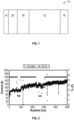
- FIG. 2 illustrates current and LFL versus run time with respect to the recombination layer.
- the LFL measurement represents the percentage of a combustible gas, such as hydrogen, propane, natural gas, in a given volume of air (e.g. the LFL for hydrogen in air is 4% by volume).
- successful hydrogen crossover mitigation exceeded 500 hrs.
- Example 1 the membrane electrode assembly was cycled between a current of 160 amps, 100 amps, and 50 amps to demonstrate effectivity of the recombination layer as oxygen dilution rates are decreased.
- the effectivity of the recombination layer is shown through the stability of the lower flammability limit (LFL) measurement collected in the oxygen stream as hydrogen gas back diffuses through the membrane.
- LFL lower flammability limit
- a certain amount of oxygen is generated, in which the percentage of hydrogen is measured in this stream to determine the amount of back diffusion through the membrane.
- the stack is then operated at currents below this value (50 A and 100 A), at which the amount of oxygen being generated is reduced, and presumably a larger percentage of hydrogen in oxygen.
- Percentage LFL is the measure of the percent of the 4% hydrogen in oxygen limit.
- Example 2 a membrane electrode assembly was manufactured including a recombination layer deposited onto a SOLVAY TM membrane, an ionomer layer deposited on the recombination layer, an anode catalyst layer applied to the ionomer layer, and a cathode catalyst layer applied to the surface of the SOLVAY TM membrane opposite that of the recombination layer.
- the recombination suspension is a platinum diamino dinitrate solution that contains 6 mg Pt/mL.
- the ionomer suspension is a 5 weight percent solids Solvay ionomer dispersion diluted to 2.5wt% using 1-propanol.
- Example 2 a membrane electrode assembly was developed in the same manner as in Example 1 using a SOLVAY membrane. This MEA was cycled between a current of 160 amps, 100 amps, and 50 amps to demonstrate effectivity of the recombination layer as oxygen dilution rates are decreased. The effectivity of the recombination layer is shown through the stability of the lower flammability limit (LFL) measurement collected in the oxygen stream as hydrogen gas back diffuses through the membrane. At 160 A, a certain amount of oxygen is generated, in which the percentage of hydrogen is measured in this stream to determine the amount of back diffusion through the membrane. The stack is then operated at currents below this value (50A and 100A), at which the amount of oxygen being generated is reduced, and presumably a larger percentage of hydrogen in oxygen. These current drops show that the LFL percentage does not increase with decreasing oxygen generation, indicating an effective recombination layer. This test demonstrates that the process is robust and can be used across various membranes.
- LFL lower flammability limit
- Example 3 a membrane electrode assembly was manufactured including a recombination layer deposited onto a NAFION TM membrane, an ionomer layer deposited on the recombination layer, an anode catalyst layer applied to the ionomer layer, and a cathode catalyst layer applied to the surface of the NAFION TM membrane opposite that of the recombination layer.
- the recombination suspension is a platinum diamino dinitrate solution that contains 6 mg Pt/mL.
- the ionomer suspension is a five weight percent Nafion dispersion diluted to 2.5wt% using IPA.
- the membrane electrode assembly was manufactured according to the process parameters listed in Table 4.
- Table 4 Parameter Recombination Layer Ionomer Layer Anode Catalyst Ink Cathode Catalyst Ink Density (mg/mL) 6 5 % Solids - - 11 8 Temperature (°C) 80 80 80 80 80 Spray Coater Height (mm) 120 120 120 120 120 Deposition Flow Rate (mL/min) 1.5 1.5 1.5 1.5 1.5 Spray Coater Travel Speed (mm/s) 120 120 120 120 120 Dwell Time (s) 10 10 10 10 10 10 10 Number of Passes 20 20 20 10
- Example 3 is used to exemplify the cell potential that is achieved through the dry deposition of the anode and cathode electrodes.
- the application of this deposition technique shows that there is no instability in cell performance resulting from the process.
- the voltage stability of the membrane electrode assembly is approaching 700 hours.
- Example 4 a membrane electrode assembly was prepared according to the methods and materials used in Example 1.
- FIG. 5 illustrates the comparison of cell potential between a membrane electrode assembly prepared according to Example 1 and a membrane electrode assembly prepared by an electrode transfer process.
- the membrane electrode assembly prepared by an electrode wet transfer process included a NAFION membrane, a recombination layer, and electrodes that included metal oxide on the anode and a pure metal on the cathode.
- the wet transfer process included hot pressing the electrodes directly to the membrane surface using a polytetrafluoroethylene binder.
- FIG. 5 illustrates that the present process does not have a negative impact on performance, as the voltages are within 50mV of each other.
- the present dry deposition methods eliminate manufacturing steps and reduce catalyst metal content loading, as compared to the conventional wet transfer process, thereby saving cost and time.
- the present methods allow for the deposition of all the layers within a single device.
Landscapes
- Chemical & Material Sciences (AREA)
- Chemical Kinetics & Catalysis (AREA)
- Engineering & Computer Science (AREA)
- Electrochemistry (AREA)
- Manufacturing & Machinery (AREA)
- General Chemical & Material Sciences (AREA)
- Sustainable Development (AREA)
- Sustainable Energy (AREA)
- Life Sciences & Earth Sciences (AREA)
- Organic Chemistry (AREA)
- Crystallography & Structural Chemistry (AREA)
- Metallurgy (AREA)
- Materials Engineering (AREA)
- Composite Materials (AREA)
- Inorganic Chemistry (AREA)
- Polymers & Plastics (AREA)
- Medicinal Chemistry (AREA)
- Health & Medical Sciences (AREA)
- Inert Electrodes (AREA)
- Electrodes For Compound Or Non-Metal Manufacture (AREA)
Description
- Fuel cells are envisaged as an electric power supply system for future mass-produced motor vehicles as well as for a large number of applications. A fuel cell is an electrochemical device that converts chemical energy directly into electrical energy. Hydrogen (H2) or molecular hydrogen is used as a fuel for the fuel cell. The molecular hydrogen is oxidized on an electrode of the cell and oxygen (O2) or molecular oxygen from the air is reduced on another electrode of the cell. The chemical reaction produces water. The great advantage of the fuel cell is that it averts emissions of atmospheric pollutant compounds at the place where electricity is generated.
- Document
US2002/0058172 discloses a membrane electrode assembly for a self-humidifying fuel cell, a method of its production, and a self-humidifying fuel cell battery include a membrane electrode assembly with a membrane electrolyte, into which at least one catalyst layer is laminated, so that water can be generated in a controlled manner within the membrane by recombination of the reaction gases H2 and O2. - Document
JP2004199943 - Document
JP2005285356 - Document
JP2004127901 - One of the major difficulties in the development of such fuel cells lies in the synthesis and supply of dihydrogen (or molecular hydrogen). On earth, hydrogen does not exist in great quantities except in combination with oxygen (in the form of water), sulphur (in the form of hydrogen sulphide) and nitrogen (as ammonia) or carbon (fossil fuels such as natural gas or petroleum). The production of molecular hydrogen therefore requires either the consumption of fossil fuels or the availability of large quantities of low-cost energy in order to obtain this hydrogen from the decomposition of water, by thermal or electrochemical means.
- One method for producing hydrogen from water consists of the use of the principle of electrolysis. To implement such methods, electrolyzers provided with proton-exchange membranes (PEMs) are known. In such an electrolyzer, an anode and a cathode are fixed on either side on the proton-exchange membrane and put into contact with water. A difference in potential is applied between the anode and the cathode. Thus, oxygen is produced at the anode by oxidation of water. The oxidation at the anode also gives rise to H+ ions that pass through the proton-exchange membrane up to the cathode, and electrons that are sent back to the cathode by the electrical supply unit. At the cathode, the H+ ions are reduced at the level of the cathode to generate molecular hydrogen.
- Such an electrolysis device comes up against undesirable effects. The proton-exchange membrane is not perfectly impermeable to gas. A part of the gases produced at the anode and the cathode thus passes through the proton-exchange membrane by diffusion. This induces problems of purity of the gas produced but also induces problems of security. It is desired that the proportion of hydrogen in oxygen remain below 4%.
- The permeability of the membranes to gas can be reduced by increasing the thickness of the proton-exchange membrane. This, however, causes an increase in the electrical resistance by making it more difficult for the H+ ions to pass through, and lowers the performance of the systems.
- To limit the permeability of a proton-exchange membrane to gases, certain developments suggest a depositing of catalyst particles inside the proton-exchange membrane. The catalyst particles seek to recombine the molecular hydrogen passing through the membrane with molecular oxygen passing through the membrane. The quantities of molecular oxygen that reach the cathode and of molecular hydrogen that reach the anode are thus reduced.
- However, the recombination reaction of the catalyst particles is exothermal and induces a loss of energy. Furthermore, such a solution is not optimized for industrial-scale applications since a part of the molecular hydrogen generated at the cathode is nevertheless lost inside the proton-exchange membrane. Furthermore, the permeability of the proton-exchange membrane to molecular hydrogen is greater than its permeability to molecular oxygen. Consequently, a part of the molecular hydrogen nevertheless reaches the anode since the quantity of molecular oxygen is insufficient in the catalyst particles disposed in the membrane.
- In order to achieve low cost, efficient, and durable fuel cells, the fabrication process of the known MEAs needs to be improved.
- The above described and other features are exemplified by the following figures and detailed description.
- A membrane electrode assembly includes an ionically conductive membrane positioned between a first electrode and a second electrode, wherein the ionically conductive membrane is in direct contact with the second electrode; a cured recombination layer deposited on a surface of the ionically conductive membrane, wherein the ionically conductive membrane is positioned between the second electrode and the recombination layer; and an ionomer layer deposited on a surface of the cured recombination layer, wherein the ionomer layer is positioned between the cured recombination layer and the first electrode.
- The invention refers to a method for manufacturing a membrane electrode assembly, the method including depositing a recombination suspension directly onto a surface of an ionically conductive membrane forming a recombination layer, wherein the recombination suspension includes a solvent and metal oxide; reducing the recombination layer to provide a cured recombination layer; and depositing an ionomer layer on a surface of the cured recombination layer.
- Refer now to the figures, which are exemplary embodiments, and wherein the like elements are numbered alike.
-
FIG. 1 is an embodiment of a membrane electrode assembly. -
FIG. 2 is a graph of current and lower flammability limit versus runtime for a membrane electrode assembly manufactured according to an embodiment of the present disclosure. -
FIG. 3 is a graph of current and lower flammability limit versus runtime for a membrane electrode assembly manufactured according to an embodiment of the present disclosure. -
FIG. 4 is a graph of cell potential versus runtime for a membrane electrode assembly manufactured according to an embodiment of the present disclosure. -
FIG. 5 is a graph of cell potential versus runtime for a membrane electrode assembly manufactured according to an embodiment of the present disclosure compared to a membrane electrode assembly manufactured according to a conventional wet process. - Disclosed herein is a method of manufacturing a membrane electrode assembly (MEA) including depositing a liquid suspension containing a platinum precursor directly onto an ionically conductive membrane (e.g., proton-exchange membrane) that, when the platinum precursor deposit layer is reduced, provides a layer that will scavenge hydrogen that has diffused back through the membrane due to cell stack pressure differential. Specifically, prior to the deposition of the catalyst layers, a recombination layer is applied to the anode side of a proton membrane and capped with an ionomer layer to prevent electrical interaction with the oxygen evolution reaction (OER) catalyst. Without the ionomer layer positioned between the anode catalyst and the recombination layer, the recombination layer may be completely ineffective or have reduced effectivity in managing the hydrogen crossover. The result is a unified catalyst coated membrane (CCM) that has durability and performance matching conventional manufacturing process.
- The present CCM allows for high differential pressure operation by keeping the hydrogen and oxygen content below the desired threshold. In addition, the process can be applied to the deposition of both cathode and anode catalyst ink suspensions. The anode ink can be applied directly onto the previously deposited ionomer layer adjacent to the recombination layer. The cathode formula ink can be applied directly to the membrane in the counter position.
- An ionic liquid suspension, typically a platinum precursor suspension, can be used to form the recombination layer that is applied directly as a dry layer onto the surface of a dry ionically conductive membrane, eliminating distortion resulting from liquid contact. The process also controls the loading of platinum on the surface required to work as an effective recombination layer, minimizes electrical resistance, and provides a uniform ionomer covering layer as the required barrier between the recombination layer and the catalyst electrode. The ionomer layer is applied in a similar process as that of the recombination layer to cap the recombination layer, i.e., a dry application directly onto the recombination layer. The recombination layer applied is reduced, which converts the platinum in solution to a metal. In an example, the recombination layer can be reduced in either an aqueous solution comprised of NaBH4. In an example, the recombination layer can be reduced in a chamber where a reducing atmosphere has been introduced in the form of either pure hydrogen gas or a forming gas.
- After reduction of the recombination layer, anode and cathode catalyst layers are applied using the same or similar device and settings as that of the recombination layer to create the discrete catalyst layers. The result of which produces a membrane electrode assembly as a single usable part comprised of an ionically conductive membrane, recombination layer including an ionomer layer cap, and both cathode and anode electrodes. The MEA prepared using the disclosed method enables a catalyst loading on the anode of 0.6 - 1.2 mg/cm2 oxygen evolution reaction (OER) catalysts and cathode ladings of 0.3 mg/cm2 hydrogen evolution reaction (HER) catalysts.
- As depicted in
FIG. 1 , the membrane electrode assembly (MEA) 10 includes ionicallyconductive membrane 12 having ananode 14 and acathode 16 disposed on opposite sides thereof. Between the ionicallyconductive membrane 12 and theanode 14 is arecombination layer 18 deposited directly on the anode side of the ionicallyconductive membrane 12. In addition, anionomer layer 20 is deposited directly onto therecombination layer 18, wherein theionomer layer 20 is positioned between therecombination layer 18 and theanode 14. - The ionically
conductive membrane 12 comprises electrolytes that are preferably solids or gels under the operating conditions of the electrochemical cell. Useful materials include proton conducting ionomers and ion exchange resins. Useful proton conducting ionomers include complexes comprising an alkali metal salt, an alkali earth metal salt, a protonic acid, or a protonic acid salt. Useful complex-forming reagents include alkali metal salts, alkaline metal earth salts, and protonic acids and protonic acid salts. Counter-ions useful in the above salts include halogen ion, perchloric ion, thiocyanate ion, trifluoromethane sulfonic ion, borofluoric ion, and the like. Representative examples of such salts include, but are not limited to, lithium fluoride, sodium iodide, lithium iodide, lithium perchlorate, sodium thiocyanate, lithium trifluoromethane sulfonate, lithium borofluoride, lithium hexafluorophosphate, phosphoric acid, sulfuric acid, trifluoromethane sulfonic acid, and the like. The alkali metal salt, alkali earth metal salt, protonic acid, or protonic acid salt is complexed with one or more polar polymers such as a polyether, polyester, or polyimide, or with a network or cross-linked polymer containing the above polar polymer as a segment. Useful polyethers include polyoxyalkylenes, such as polyethylene glycol, polyethylene glycol monoether, and polyethylene glycol diether; copolymers of at least one of these polyethers, such as poly(oxyethylene-co-oxypropylene) glycol, poly(oxyethylene-co-oxypropylene) glycol monoether, and poly(oxyethylene-co-oxypropylene) glycol diether; condensation products of ethylenediamine with the above polyoxyalkylenes; and esters, such as phosphoric acid esters, aliphatic carboxylic acid esters or aromatic carboxylic acid esters of the above polyoxyalkylenes. Additionally, copolymers of, e.g., polyethylene glycol with dialkylsiloxanes, maleic anhydride, or polyethylene glycol monoethyl ether with methacrylic acid, exhibit sufficient ionic conductivity to be useful. The membrane 202 can also comprises a combination comprising at least one of the above materials. - Ion-exchange resins useful as proton conducting materials include hydrocarbon- and fluorocarbon-type resins. Hydrocarbon-type ion-exchange resins include phenolic resins, condensation resins such as phenol-formaldehyde, polystyrene, styrene-divinyl benzene copolymers, styrene-butadiene copolymers, styrene-divinylbenzene-vinylchloride terpolymers, and the like, that are imbued with cation-exchange ability by sulfonation, or are imbued with anion-exchange ability by chloromethylation followed by conversion to the corresponding quaternary amine.
- Fluorocarbon-type ion-exchange resins may include hydrates of tetrafluoroethylene-perfluorosulfonyl ethoxyvinyl ether or tetrafluoroethylene-hydroxylated (perfluoro vinyl ether) copolymers. When oxidation and/or acid resistance is desirable, for instance, at the cathode of a fuel cell, fluorocarbon-type resins having sulfonic, carboxylic and/or phosphoric acid functionality are preferred. Fluorocarbon-type resins may exhibit excellent resistance to oxidation by halogen, strong acids and bases. One family of fluorocarbon-type resins having sulfonic acid group functionality is NAFION® resins (commercially available from E.I. du Pont de Nemours and Company, Wilmington, Del.)
- The
recombination layer 18 can include a recombination catalyst precursor solution. The recombination catalyst precursor solution can include a recombination catalyst. Suitable hydrogen/oxygen recombination catalysts which can be used are preferably platinum, ruthenium, iridium, palladium, rhodium, mixtures of these metals with each other; as well as, alloys between any or more of the above, platinum metals with transition metals (e.g., cobalt, nickel, etc.). Other suitable hydrogen/oxygen recombination catalysts are Ag, Au, Sn, Si, Ti, Zr, Al, Hf, Ta, Nb, Ce and combinations thereof including oxides thereof where applicable. The recombination layer can be deposited onto ionically conductive membrane as thin layers of less than or equal to 10 microns, preferably less than or equal to 100 nm, most preferably less than or equal to 20 nm, as thin layers reduce the cost of the possible noble metal constituents. In one embodiment of the invention, the recombination catalyst are non-porous in order to reduce gas diffusion within the recombination layer it is most preferable to use unsupported hydrogen/oxygen recombination catalysts which afford the desired lower gas porosity and are generally thought to produce less radicals which would damage the ionically conductive membrane. - An ionomer layer is provided between the recombination layer and the anode to prevent electrical interaction between the recombination layer and the anode catalyst. The ionomer layer can include a solid proton transmissive electrolyte membrane. The ionomer layer can include perfluorosulfonic acid (PFSA), perfluorocyclobutane (PFCB), polyvinylidene fluoride (PVDF), polyether ether ketone (PEEK), polystyrene sulfonic acid (PSSA), poly(trifluorostyrene) sulfonic acid, polyvinylphosphoric acid (PVPA), polyacrylic acid (PAA), polyvinyl sulfonic acid (PVSA), sulfonated polyphenylene oxide (PPO), polybenzimidazle (PBI), brominated polyfluorene ether sulfone (BrPFES), polysulfone trimethylamine (PSF/TMA), and combinations thereof. In an example, the ionomer layer can include perfluorosulfonic acid (PFSA), perfluorocyclobutane (PFCB), polyvinylidene fluoride (PVDF), and combinations thereof. For example, the ionomer layer can include perfluorosulfonic acid (PFSA) membrane, a commercial example of which is NAFION™.
- The
recombination layer 18 and theionomer layer 20 are on the anode side of the ionicallyconductive membrane 12. However, the scope of the invention includes embodiments wherein instead therecombination layer 18 and theionomer layer 20 are on the cathode side of the ionicallyconductive membrane 12. - The anode and cathode can comprise catalyst suitable for performing an electrochemical reaction (i.e., electrolyzing water to produce hydrogen and oxygen). Suitable electrodes comprise, but are not limited to, platinum, palladium, rhodium, carbon, gold, tantalum, tungsten, ruthenium, iridium, osmium, as well as alloys and combinations comprising at least one of the foregoing, and the like. The
anode 14 andcathode 16 can be formed on the ionicallyconductive membrane 12, or may be layered adjacent to, but in ionic communication with, the ionicallyconductive membrane 12. In an example, thecathode 16 can be in direct contact with the ionicallyconductive membrane 12, wherein theanode 14 is not in direct contact with the ionicallyconductive membrane 12 but is in ionic communication with the ionicallyconductive membrane 12 via theionomer layer 20 andrecombination layer 18. - A catalyst ink solution (e.g., a catalyst component, a suspension medium, and optionally a binder) can be used to form the
anode 14 and thecathode 16. The catalyst consumption and utilization in an electrode may be improved by forming an ink having the catalyst dispersed in a solvent base. The solvent is preferably of a nature similar to that of the ionicallyconductive membrane 12. The anode catalyst ink solution can be deposited on theionomer layer 20 to form theanode 14, and the cathode catalyst ink solution can be deposited on the surface of the ionicallyconductive membrane 12 opposite that of therecombination layer 18. - Suitable materials for catalyst component include, but is not limited to, platinum, palladium, rhodium, carbon, gold, tantalum, tungsten, ruthenium, iridium, osmium, alloys comprising at least one of the foregoing, and the like. Platinum, e.g., platinum black, is preferred for the hydrogen side electrode. The catalyst component may be incorporated in the catalyst ink precursor solution in a form of a powder. For example, the catalyst component may have a particle size of about 10 nanometers to about 100 nanometers (nm), with about 15 nm to about 50 nm preferred.
- Unlike current electrode designs, the electrodes disclosed herein have a much lower loading. For example, current electrodes designs may have a catalyst metal (e.g., platinum) loading of about 2 milligrams per square centimeter (mg/cm2) to about 7 mg/cm2, whereas electrodes disclosed herein have a platinum loading of less than or equal to about 1.5 mg/cm2, with a loading of about 0.5 mg/cm2 to about 0.8 mg/cm2 preferred. While attaining substantially the same activity, this is a significant improvement over existing electrode loadings, which allows for a reduction in the catalyst material used. As such, electrodes can be made in a shorter amount of time and at a reduced cost.
- Conventionally, catalyst layers deposited on a polymer electrolyte membrane are first deposited indirectly to the membrane by coating the catalyst on a decal substrate that is then transferred to the membrane by hot-pressing. However, such conventional processes have exhibited failure along the catalyst edge. For example, the membrane has been shown to tear adjacent to the outer edge of the catalyst layer on both the anode and cathode sides of the MEA. This failure typically corresponds to the edge of the decal substrate during the hot-pressing and translates to a possible weakening of the membrane along the catalyst edge.
- The present method does not require a decal for depositing the recombination layer, the ionomer layer, nor the catalyst layers. As a result, expense and time are saved in the manufacturing process. In addition, a high quality MEA is produced without the disadvantages associated with using processes that utilize decals and solution based applications.
- The recombination layer, the ionomer layer, and the catalyst layers are applied by directly spraying the layer material directly onto the appropriate surface for application. For example, the recombination layer can be deposited by spraying the recombination precursor solution onto the surface of the ionically conductive membrane, wherein the solvent is substantially evaporated from the recombination precursor solution before the recombination precursor solution contacts the ionically conductive membrane surface. As a result, a substantially dry recombination layer is directly applied to the ionically conductive membrane, thereby avoiding the disadvantages of a solution based approach. The ionomer layer and catalyst layers are applied in a similar manner.
- Embodiments of the specific process parameters for applying the recombination layer, ionomer layer, and catalyst ink are listed in Table 1 and include ink density, system temperature, spray coater height, deposition flow rates, spray coater travel speed, dwell time, and number of passes based on required loadings.
Table 1 Parameter Recombination Layer Ionomer Layer Anode Catalyst Ink Cathode Catalyst Ink Density (mg/mL) 6 2.5-5 % Solids - - 4-11 4-8 Temperature (°C) 80 80 80 80 Spray Coater Height (mm) 120 120 120 120 Deposition Flow Rate (mL/min) 1.5 1.5 1.5 1.5 Spray Coater Travel Speed (mm/s) 120 120 120 120 Dwell Time (s) 10-30 10-30 10-30 10-30 Number of Passes 20 10-20 20-40 10-20 - The membrane electrode assemblies used in the examples were prepared by a Ultrasonic Systems, Inc. Prism Benchtop model.
- In Example 1, a membrane electrode assembly was manufactured including a recombination layer deposited onto a NAFION™ membrane, an ionomer layer deposited on the recombination layer, an anode catalyst layer applied to the ionomer layer, and a cathode catalyst layer applied to the surface of the NAFION™ membrane opposite that of the recombination layer.
- The recombination suspension used included a platinum diamine dinitrate solution containing 6 mg Pt/ml. The ionomer layer included a 5 weight percent solids NAFION dispersion diluted to 2.5 wt% using isopropyl alcohol.
- The membrane electrode assembly was manufactured according to the process parameters listed in Table 2.
Table 2 Parameter Recombination Layer Ionomer Layer Anode Catalyst Ink Cathode Catalyst Ink Density (mg/mL) 6 5 - - % Solids - - 11 8 Temperature (°C) 80 80 80 80 Spray Coater Height (mm) 120 120 120 120 Deposition Flow Rate (mL/min) 1.5 1.5 1.5 1.5 Spray Coater Travel Speed (mm/s) 120 120 120 120 Dwell Time (s) 30 30 30 30 Number of Passes 20 20 20 10 -
FIG. 2 illustrates current and LFL versus run time with respect to the recombination layer. The LFL measurement represents the percentage of a combustible gas, such as hydrogen, propane, natural gas, in a given volume of air (e.g. the LFL for hydrogen in air is 4% by volume). As demonstrated inFIG. 2 , successful hydrogen crossover mitigation exceeded 500 hrs. - In Example 1, the membrane electrode assembly was cycled between a current of 160 amps, 100 amps, and 50 amps to demonstrate effectivity of the recombination layer as oxygen dilution rates are decreased. The effectivity of the recombination layer is shown through the stability of the lower flammability limit (LFL) measurement collected in the oxygen stream as hydrogen gas back diffuses through the membrane. At 160 A, a certain amount of oxygen is generated, in which the percentage of hydrogen is measured in this stream to determine the amount of back diffusion through the membrane. The stack is then operated at currents below this value (50 A and 100 A), at which the amount of oxygen being generated is reduced, and presumably a larger percentage of hydrogen in oxygen. These current drops demonstrate that the LFL percentage does not increase with decreasing oxygen generation, indicating an effective recombination layer. Percentage LFL is the measure of the percent of the 4% hydrogen in oxygen limit.
- In Example 2, a membrane electrode assembly was manufactured including a recombination layer deposited onto a SOLVAY™ membrane, an ionomer layer deposited on the recombination layer, an anode catalyst layer applied to the ionomer layer, and a cathode catalyst layer applied to the surface of the SOLVAY™ membrane opposite that of the recombination layer.
- The recombination suspension is a platinum diamino dinitrate solution that contains 6 mg Pt/mL. The ionomer suspension is a 5 weight percent solids Solvay ionomer dispersion diluted to 2.5wt% using 1-propanol.
Table 3 Parameter Recombination Layer Ionomer Layer Anode Catalyst Ink Cathode Catalyst Ink Density (mg/mL) 6 2.5 % Solids - - 11 5 Temperature (°C) 80 80 80 80 Spray Coater Height (mm) 120 120 120 120 Deposition Flow Rate (mL/min) 1.5 1.5 1.5 1.5 Spray Coater Travel Speed (mm/s) 120 120 120 120 Dwell Time (s) 10 10 10 10 Number of Passes 20 20 20 20 - In Example 2, a membrane electrode assembly was developed in the same manner as in Example 1 using a SOLVAY membrane. This MEA was cycled between a current of 160 amps, 100 amps, and 50 amps to demonstrate effectivity of the recombination layer as oxygen dilution rates are decreased. The effectivity of the recombination layer is shown through the stability of the lower flammability limit (LFL) measurement collected in the oxygen stream as hydrogen gas back diffuses through the membrane. At 160 A, a certain amount of oxygen is generated, in which the percentage of hydrogen is measured in this stream to determine the amount of back diffusion through the membrane. The stack is then operated at currents below this value (50A and 100A), at which the amount of oxygen being generated is reduced, and presumably a larger percentage of hydrogen in oxygen. These current drops show that the LFL percentage does not increase with decreasing oxygen generation, indicating an effective recombination layer. This test demonstrates that the process is robust and can be used across various membranes.
- In Example 3, a membrane electrode assembly was manufactured including a recombination layer deposited onto a NAFION™ membrane, an ionomer layer deposited on the recombination layer, an anode catalyst layer applied to the ionomer layer, and a cathode catalyst layer applied to the surface of the NAFION™ membrane opposite that of the recombination layer.
- The recombination suspension is a platinum diamino dinitrate solution that contains 6 mg Pt/mL. The ionomer suspension is a five weight percent Nafion dispersion diluted to 2.5wt% using IPA.
- The membrane electrode assembly was manufactured according to the process parameters listed in Table 4.
Table 4 Parameter Recombination Layer Ionomer Layer Anode Catalyst Ink Cathode Catalyst Ink Density (mg/mL) 6 5 % Solids - - 11 8 Temperature (°C) 80 80 80 80 Spray Coater Height (mm) 120 120 120 120 Deposition Flow Rate (mL/min) 1.5 1.5 1.5 1.5 Spray Coater Travel Speed (mm/s) 120 120 120 120 Dwell Time (s) 10 10 10 10 Number of Passes 20 20 20 10 - As shown in
FIG. 4 , Example 3 is used to exemplify the cell potential that is achieved through the dry deposition of the anode and cathode electrodes. The application of this deposition technique shows that there is no instability in cell performance resulting from the process. As demonstrated inFIG. 4 , the voltage stability of the membrane electrode assembly is approaching 700 hours. - In Example 4, a membrane electrode assembly was prepared according to the methods and materials used in Example 1.
FIG. 5 illustrates the comparison of cell potential between a membrane electrode assembly prepared according to Example 1 and a membrane electrode assembly prepared by an electrode transfer process. The membrane electrode assembly prepared by an electrode wet transfer process included a NAFION membrane, a recombination layer, and electrodes that included metal oxide on the anode and a pure metal on the cathode. The wet transfer process included hot pressing the electrodes directly to the membrane surface using a polytetrafluoroethylene binder.FIG. 5 illustrates that the present process does not have a negative impact on performance, as the voltages are within 50mV of each other. - The present dry deposition methods eliminate manufacturing steps and reduce catalyst metal content loading, as compared to the conventional wet transfer process, thereby saving cost and time. In addition, the present methods allow for the deposition of all the layers within a single device.
- The term "substantially" is utilized herein to represent the inherent degree of uncertainty that may be attributed to any quantitative comparison, value, measurement, or other representation. The term "substantially" is also utilized herein to represent the degree by which a quantitative representation may vary from a stated reference without resulting in a change in the basic function of the subject matter at issue.
- While the invention has been described with reference to an exemplary embodiment, it will be understood by those skilled in the art that various changes may be made and equivalents may be substituted for elements thereof without departing from the scope of the invention. In addition, many modifications may be made to adapt a particular situation or material to the teachings of the invention without departing from the essential scope thereof. Therefore, it is intended that the invention not be limited to the particular embodiment disclosed as the best mode contemplated for carrying out this invention, but that the invention will include all embodiments falling within the scope of the appended claims. Moreover, the use of the terms first, second, etc. do not denote any order or importance, but rather the terms first, second, etc. are used to distinguish one element from another. Furthermore, the use of the terms a, an, etc. do not denote a limitation of quantity, but rather denote the presence of at least one of the referenced item.
Claims (11)
- A method for manufacturing a membrane electrode assembly, the method comprising:depositing a recombination suspension directly onto a surface of an ionically conductive membrane forming a recombination layer, wherein the recombination suspension includes a solvent and metal oxide;reducing the metal oxide of recombination layer to provide a cured recombination layer comprising the metal; anddepositing an ionomer layer on a surface of the cured recombination layer.
- The method of Claim 1, further comprising depositing a first electrode catalyst layer on a surface of the ionomer layer, wherein the ionomer layer is positioned between the cured recombination layer and the first electrode catalyst layer.
- The method of any of Claims 1 to 2, further comprising depositing a second electrode catalyst layer on a surface of the ionically conductive membrane opposite of the cured recombination layer, wherein the ionically conductive membrane is positioned between the second electrode catalyst layer and the cured recombination layer.
- The method of any of Claims 1 to 3, wherein depositing the recombination suspension includes spraying the recombination suspension onto the surface of the ionically conductive membrane, wherein the recombination suspension is substantially free of solvent when the suspension contacts the surface of the ionically conductive membrane.
- The method of any of Claims 1 to 4, wherein depositing the recombination suspension includes spraying the recombination suspension onto the surface of the ionically conductive membrane, wherein the deposition flow rate is 1.0 to 2.0 mL/min, wherein the density of the recombination suspension is 4 to 8 mg/mL.
- The method of any of Claims 1 to 5, wherein the recombination suspension includes platinum oxide.
- The method of any of Claims 1 to 6, wherein depositing the ionomer layer includes spraying a ionomer layer solution onto the surface of the cured recombination layer, wherein the deposition flow rate is 1.0 to 2.0 mL/min, wherein the percent solids of the ionomer layer solution is 2.5 to 5 %.
- The method of any of Claims 2 to 3, wherein depositing the first electrode catalyst layer includes spraying a first electrode catalyst solution onto the surface of the ionomer layer, wherein the deposition flow rate is 1.0 to 2.0 mL/min, wherein the percent solids of the first electrode catalyst solution is 4 to 11 %.
- The method of any of Claims 2 to 3, wherein depositing the second electrode catalyst layer includes spraying a second electrode catalyst solution onto the surface of the ionically conductive membrane, wherein the deposition flow rate is 1.0 to 2.0 mL/min, wherein the percent solids of the second electrode catalyst solution is 4 to 8 %.
- The method of any of Claims 1 to 9, wherein the cured recombination layer includes platinum.
- The method of any of Claims 1 to 10, wherein the ionomer layer provides an electrical barrier between the recombination layer and the first electrode.
Applications Claiming Priority (2)
| Application Number | Priority Date | Filing Date | Title |
|---|---|---|---|
| US201662379311P | 2016-08-25 | 2016-08-25 | |
| PCT/US2017/047082 WO2018038986A1 (en) | 2016-08-25 | 2017-08-16 | Membrane electrode assembly and method of making the same |
Publications (4)
| Publication Number | Publication Date |
|---|---|
| EP3504747A1 EP3504747A1 (en) | 2019-07-03 |
| EP3504747A4 EP3504747A4 (en) | 2020-01-01 |
| EP3504747C0 EP3504747C0 (en) | 2023-11-01 |
| EP3504747B1 true EP3504747B1 (en) | 2023-11-01 |
Family
ID=61240743
Family Applications (1)
| Application Number | Title | Priority Date | Filing Date |
|---|---|---|---|
| EP17844149.9A Active EP3504747B1 (en) | 2016-08-25 | 2017-08-16 | Membrane electrode assembly and method of making the same |
Country Status (5)
| Country | Link |
|---|---|
| US (1) | US10700373B2 (en) |
| EP (1) | EP3504747B1 (en) |
| CN (1) | CN109690854B (en) |
| ES (1) | ES2968670T3 (en) |
| WO (1) | WO2018038986A1 (en) |
Families Citing this family (7)
| Publication number | Priority date | Publication date | Assignee | Title |
|---|---|---|---|---|
| GB201621963D0 (en) * | 2016-12-22 | 2017-02-08 | Johnson Matthey Plc | Catalyst-coated membrane having a laminate structure |
| US11560632B2 (en) * | 2018-09-27 | 2023-01-24 | 3M Innovative Properties Company | Membrane, membrane electrode assembly, and water electrolyzer including the same |
| KR102158604B1 (en) * | 2018-11-02 | 2020-09-22 | 한국에너지기술연구원 | Alkaline electrolysis cell comprising gas-barrier layer and method for manufacturing the same |
| JP2020094282A (en) * | 2018-12-11 | 2020-06-18 | カーリットホールディングス株式会社 | Electrode for water electrolysis and method for producing the same |
| CN112259757B (en) * | 2020-12-17 | 2022-05-17 | 安徽明天氢能科技股份有限公司 | Membrane electrode sealing filler and preparation method thereof |
| AU2022216247A1 (en) * | 2021-02-02 | 2023-08-31 | Plug Power Inc. | Proton exchange membrane water electrolyzer membrane electrode assembly |
| CN115332590B (en) * | 2022-08-04 | 2025-09-05 | 大连理工大学 | A membrane electrode with a hydrogen dissipation layer and its preparation method and application |
Family Cites Families (58)
| Publication number | Priority date | Publication date | Assignee | Title |
|---|---|---|---|---|
| JPH0622144B2 (en) | 1986-04-18 | 1994-03-23 | 三菱電機株式会社 | Fuel cell |
| FR2624885B1 (en) | 1987-12-17 | 1991-01-04 | Commissariat Energie Atomique | SOLID POLYMER ELECTRODE-ELECTROLYTE ASSEMBLY USED FOR EXAMPLE FOR THE ELECTROLYSIS OF WATER, AND ITS MANUFACTURING METHOD |
| US7098163B2 (en) * | 1998-08-27 | 2006-08-29 | Cabot Corporation | Method of producing membrane electrode assemblies for use in proton exchange membrane and direct methanol fuel cells |
| DE19917812C2 (en) * | 1999-04-20 | 2002-11-21 | Siemens Ag | Membrane electrode unit for a self-moistening fuel cell, method for its production and fuel cell battery with such a membrane electrode unit |
| US6403245B1 (en) | 1999-05-21 | 2002-06-11 | Microcoating Technologies, Inc. | Materials and processes for providing fuel cells and active membranes |
| WO2002045196A2 (en) * | 2000-11-30 | 2002-06-06 | Mti Microfuel Cells, Inc. | Fuel cell membrane and system with integrated gas separation |
| EP2009720B1 (en) * | 2001-01-19 | 2010-12-29 | Panasonic Corporation | Electrolyte membrane-electrode assembly for fuel cell |
| JP4534423B2 (en) * | 2002-07-30 | 2010-09-01 | アイシン精機株式会社 | Fuel cell control method |
| US7112386B2 (en) | 2002-09-04 | 2006-09-26 | Utc Fuel Cells, Llc | Membrane electrode assemblies with hydrogen peroxide decomposition catalyst |
| US7977005B2 (en) * | 2002-10-08 | 2011-07-12 | GM Global Technology Operations LLC | Edge-protected catalyst-coated membrane electrode assemblies |
| US20050014037A1 (en) * | 2002-12-04 | 2005-01-20 | Chris Boyer | Fuel cell with recombination catalyst |
| JP4288561B2 (en) * | 2002-12-17 | 2009-07-01 | トヨタ自動車株式会社 | Solid polymer electrolyte membrane, membrane-electrode assembly, and solid polymer electrolyte fuel cell |
| US20040175498A1 (en) * | 2003-03-06 | 2004-09-09 | Lotfi Hedhli | Method for preparing membrane electrode assemblies |
| JP3983259B2 (en) | 2003-06-27 | 2007-09-26 | 旭化成ケミカルズ株式会社 | Polymer electrolyte membrane having high durability and method for producing the same |
| US7291419B2 (en) | 2004-01-22 | 2007-11-06 | General Motors Corporation | Durable membrane electrode assembly catalyst coated diffusion media with no lamination to membrane |
| US7955758B2 (en) | 2004-01-22 | 2011-06-07 | GM Global Technology Operations LLC | Membrane electrode assembly prepared by direct spray of catalyst to membrane |
| JP2005285356A (en) * | 2004-03-26 | 2005-10-13 | Mitsubishi Electric Corp | Membrane electrode assembly for fuel cell and method for producing the same |
| CN100541887C (en) | 2004-04-26 | 2009-09-16 | 东芝燃料电池动力系统公司 | Fuel cell and fuel cell manufacturing method |
| US8465858B2 (en) * | 2004-07-28 | 2013-06-18 | University Of South Carolina | Development of a novel method for preparation of PEMFC electrodes |
| AU2005314211B2 (en) * | 2004-12-09 | 2010-07-08 | Oned Material, Inc. | Nanowire-based membrane electrode assemblies for fuel cells |
| CN101120466B (en) * | 2004-12-28 | 2010-06-16 | Utc电力公司 | Membrane electrode assembly with hydrogen peroxide decomposition catalyst |
| ITFI20050002A1 (en) * | 2005-01-11 | 2006-07-12 | Acta Spa | ASSEMBLED MAMBRANA-ELECTRODES FOR FUEL CELLS, THEIR MANUFACTURE AND USE AND FUEL CELLS THAT COUNT |
| DE102005038612A1 (en) * | 2005-08-16 | 2007-02-22 | Basf Ag | Process for the preparation of double-sided catalyst coated membranes |
| WO2007059278A2 (en) | 2005-11-16 | 2007-05-24 | General Motors Corporation | Method of making a membrane electrode assembly comprising a vapor barrier layer, a gas diffusion layer, or both |
| JP2007250265A (en) | 2006-03-14 | 2007-09-27 | Toyota Motor Corp | REINFORCED ELECTROLYTE MEMBRANE FOR FUEL CELL, METHOD FOR PRODUCING THE SAME, MEMBRANE-ELECTRODE ASSEMBLY FOR FUEL CELL, AND SOLID POLYMER FUEL CELL HAVING THE SAME |
| US20080044720A1 (en) * | 2006-08-18 | 2008-02-21 | Elchem Tech Co., Ltd. | Membrane electrode assembly having porous electrode layers, manufacturing method thereof, and electrochemical cell comprising the same |
| US8318385B2 (en) * | 2006-09-19 | 2012-11-27 | Nanotek Instruments, Inc. | Process for producing fuel cell electrode |
| US20100047631A1 (en) | 2006-10-24 | 2010-02-25 | Utc Power Corporation | Membrane electrode assembly having protective layer and method for mitigating membrane decay |
| US20080107945A1 (en) | 2006-11-08 | 2008-05-08 | Gm Global Technology Operations, Inc. | Fuel cell substrate with an overcoat |
| US9023553B2 (en) * | 2007-09-04 | 2015-05-05 | Chemsultants International, Inc. | Multilayered composite proton exchange membrane and a process for manufacturing the same |
| DE102007044246A1 (en) | 2007-09-11 | 2009-03-12 | Volkswagen Ag | Membrane electrode unit with hydrogenatable material for a fuel cell |
| US20090081527A1 (en) | 2007-09-24 | 2009-03-26 | Ping He | Fuel cell system |
| JP5141167B2 (en) | 2007-10-02 | 2013-02-13 | ソニー株式会社 | Electrolytic solution and electrochemical device |
| US8257979B2 (en) | 2007-11-12 | 2012-09-04 | GM Global Technology Operations LLC | Method for characterizing the porosity in fuel cell electrodes |
| JP4773582B2 (en) | 2008-10-31 | 2011-09-14 | パナソニック株式会社 | Membrane electrode assembly and fuel cell |
| CA2766022C (en) | 2009-06-26 | 2016-06-21 | Nissan Motor Co., Ltd. | Gas diffusion electrode and production method for same; membrane electrode assembly and production method for same |
| US9172107B2 (en) | 2009-11-10 | 2015-10-27 | Daimler Ag | Composite proton conducting electrolyte with improved additives for fuel cells |
| US8642202B2 (en) | 2010-01-29 | 2014-02-04 | Samsung Electronics Co., Ltd. | Organic electrolyte solution and redox flow battery including the same |
| US9391336B2 (en) * | 2010-08-23 | 2016-07-12 | Audi Ag | Mixed-ionomer electrode |
| JP5655079B2 (en) | 2010-09-09 | 2015-01-14 | 株式会社ブリヂストン | tire |
| US8628880B2 (en) | 2010-09-28 | 2014-01-14 | Battelle Memorial Institute | Redox flow batteries based on supporting solutions containing chloride |
| JP5705325B2 (en) * | 2010-09-30 | 2015-04-22 | ユーティーシー パワー コーポレイション | Hot pressed direct deposition catalyst layer |
| GB201021352D0 (en) | 2010-12-16 | 2011-01-26 | Johnson Matthey Plc | Catalyst layer |
| US20130089805A1 (en) | 2011-10-11 | 2013-04-11 | University Of Central Florida Research Foundation, Inc. | Electroactive species in layer between electrode and membrane for fuel cells |
| KR101890747B1 (en) | 2011-11-03 | 2018-10-01 | 삼성전자주식회사 | Ion conductor filling composition, method of preparing ion exchange membrane, ion exchange membrane and redox flow battery |
| US20130157167A1 (en) | 2011-12-20 | 2013-06-20 | GM Global Technology Operations LLC | Alternate material for electrode topcoat |
| US9178238B2 (en) | 2012-04-03 | 2015-11-03 | Gm Global Technology Operations, Llc | Rubber crack mitigants in polyelectrolyte membranes |
| CN104822861B (en) | 2012-09-24 | 2017-03-08 | 二氧化碳材料公司 | For carbon dioxide conversion is usable fuel and the apparatus and method of chemicals |
| JPWO2014087958A1 (en) | 2012-12-03 | 2017-01-05 | Jsr株式会社 | Membrane-electrode assembly manufacturing method, membrane-electrode assembly, laminate for forming membrane-electrode assembly, polymer electrolyte fuel cell, and water electrolysis apparatus |
| KR102128134B1 (en) | 2012-12-03 | 2020-06-30 | 악신 워터 테크놀로지스 아이엔씨. | Efficient treatment of wastewater using electrochemical cell |
| GB201302014D0 (en) | 2013-02-05 | 2013-03-20 | Johnson Matthey Fuel Cells Ltd | Use of an anode catalyst layer |
| US10090531B2 (en) | 2013-02-26 | 2018-10-02 | Toyoto Motor Europe Nv/Sa | Vertically aligned titanium oxide nanotubes for fuel cell electrodes |
| FR3003694B1 (en) * | 2013-03-22 | 2015-04-24 | Commissariat Energie Atomique | METHOD FOR MANUFACTURING A MEMBRANE-ELECTRODE ASSEMBLY |
| US10573901B2 (en) | 2013-04-25 | 2020-02-25 | Tanaka Kikinzoku Kogyo K.K. | Catalyst and manufacturing method thereof, and electrode catalyst layer using the catalyst |
| CN103326032B (en) * | 2013-05-30 | 2015-07-15 | 上海交通大学 | Method for preparing platinum gradient-distribution catalyst layer structure of proton exchange membrane fuel cell |
| CN105474446B (en) | 2013-08-07 | 2018-07-03 | 住友电气工业株式会社 | Redox flow batteries |
| FR3017747A1 (en) * | 2014-02-18 | 2015-08-21 | Commissariat Energie Atomique | PROCESS FOR THE ELECTRODEPOSITION PREPARATION OF AN ELECTRODE MEMBRANE ASSEMBLY FOR A FUEL CELL |
| US20160064741A1 (en) | 2014-09-02 | 2016-03-03 | GM Global Technology Operations LLC | Electrode design with optimal ionomer content for polymer electrolyte membrane fuel cell |
-
2017
- 2017-08-16 CN CN201780051350.2A patent/CN109690854B/en active Active
- 2017-08-16 EP EP17844149.9A patent/EP3504747B1/en active Active
- 2017-08-16 ES ES17844149T patent/ES2968670T3/en active Active
- 2017-08-16 WO PCT/US2017/047082 patent/WO2018038986A1/en not_active Ceased
- 2017-08-22 US US15/682,803 patent/US10700373B2/en active Active
Also Published As
| Publication number | Publication date |
|---|---|
| EP3504747C0 (en) | 2023-11-01 |
| EP3504747A4 (en) | 2020-01-01 |
| EP3504747A1 (en) | 2019-07-03 |
| ES2968670T3 (en) | 2024-05-13 |
| US10700373B2 (en) | 2020-06-30 |
| WO2018038986A1 (en) | 2018-03-01 |
| CN109690854A (en) | 2019-04-26 |
| US20180062192A1 (en) | 2018-03-01 |
| CN109690854B (en) | 2023-08-22 |
Similar Documents
| Publication | Publication Date | Title |
|---|---|---|
| EP3504747B1 (en) | Membrane electrode assembly and method of making the same | |
| EP1760812B1 (en) | Liquid composition, process for its production, and process for producing membrane electrode assembly for polymer electrolyte fuel cell | |
| KR102225982B1 (en) | Catalyst | |
| US20040109816A1 (en) | Proton conductive carbon material for fuel cell applications | |
| US20060099482A1 (en) | Fuel cell electrode | |
| KR101520119B1 (en) | Catalyst layer | |
| US20080096093A1 (en) | Electro-catalyst compositions for fuel cells | |
| CN115697553A (en) | Anion-exchange membrane electrolyzer with platinum-group metal-free self-supporting oxygen evolution electrode | |
| CN119032201A (en) | Catalyst-coated ion-conducting membranes comprising conductive polymers for water electrolysis | |
| KR100684836B1 (en) | Catalyst complex for fuel cell, method for manufacturing the same, membrane-electrode assembly including the same, and fuel cell system comprising the same | |
| US20230366112A1 (en) | Method of preparing metal oxide catalysts for oxygen evolution | |
| CN100547834C (en) | Electrode for fuel cell, membrane electrode assembly for fuel cell, and fuel cell system | |
| KR101312971B1 (en) | Hydrocarbon based polyelectrolyte separation membrane surface-treated with fluorinated ionomer, membrane electrode assembly, and fuel cell | |
| EP3439089A1 (en) | Nanostructured electrode for polymer electrolyte membrane fuel cell, and manufacturing method therefor | |
| KR102296050B1 (en) | Electrolyte membrane for fuel cell and preparation method thereof | |
| JP2006155987A (en) | ELECTRODE FOR FUEL CELL, MANUFACTURING METHOD THEREOF, AND FUEL CELL USING THE SAME | |
| KR100481591B1 (en) | Polyelectrolyte nanocomposite membrane and the preparation method thereof and the fuel cell using the prepared polyelectrolyte nanocomposite membrane | |
| JP5458774B2 (en) | Electrolyte membrane-electrode assembly | |
| KR20170127250A (en) | Electrolyte membrane and fuel cell comprising the same | |
| JP2018085260A (en) | Electrocatalyst production method | |
| KR20160083713A (en) | Polymer electrolyte membrane for fuel cell comprising hydrogen and oxygen eliminating layer, membrane electrode assembly comprising the same and fuel cell comprising the same | |
| KR20170078271A (en) | Electrolyte membrane for fuel cell, membrane-electrode assembly and fuel cell using the same | |
| Fujiwara | Electrochemical devices with metal-polymer electrolyte membrane composites | |
| KR20170004747A (en) | Membrane electrode assembly, fuel cell comprising the membrane electrode assembly and battery module having the fuel cell | |
| KR20080041846A (en) | Membrane-electrode assembly for fuel cell, manufacturing method thereof and fuel cell system comprising same |
Legal Events
| Date | Code | Title | Description |
|---|---|---|---|
| STAA | Information on the status of an ep patent application or granted ep patent |
Free format text: STATUS: THE INTERNATIONAL PUBLICATION HAS BEEN MADE |
|
| PUAI | Public reference made under article 153(3) epc to a published international application that has entered the european phase |
Free format text: ORIGINAL CODE: 0009012 |
|
| STAA | Information on the status of an ep patent application or granted ep patent |
Free format text: STATUS: REQUEST FOR EXAMINATION WAS MADE |
|
| 17P | Request for examination filed |
Effective date: 20190214 |
|
| AK | Designated contracting states |
Kind code of ref document: A1 Designated state(s): AL AT BE BG CH CY CZ DE DK EE ES FI FR GB GR HR HU IE IS IT LI LT LU LV MC MK MT NL NO PL PT RO RS SE SI SK SM TR |
|
| AX | Request for extension of the european patent |
Extension state: BA ME |
|
| DAV | Request for validation of the european patent (deleted) | ||
| DAX | Request for extension of the european patent (deleted) | ||
| A4 | Supplementary search report drawn up and despatched |
Effective date: 20191203 |
|
| RIC1 | Information provided on ipc code assigned before grant |
Ipc: H01M 4/86 20060101ALI20191127BHEP Ipc: H01M 8/1053 20160101AFI20191127BHEP Ipc: H01M 4/88 20060101ALI20191127BHEP Ipc: C25B 1/06 20060101ALI20191127BHEP Ipc: H01M 8/1004 20160101ALI20191127BHEP Ipc: H01M 8/1027 20160101ALI20191127BHEP Ipc: H01M 8/1025 20160101ALI20191127BHEP Ipc: C08G 65/40 20060101ALI20191127BHEP Ipc: H01M 8/1023 20160101ALI20191127BHEP Ipc: H01M 8/1039 20160101ALI20191127BHEP Ipc: C25B 13/08 20060101ALI20191127BHEP Ipc: C01G 55/00 20060101ALI20191127BHEP Ipc: H01M 8/1041 20160101ALI20191127BHEP |
|
| GRAP | Despatch of communication of intention to grant a patent |
Free format text: ORIGINAL CODE: EPIDOSNIGR1 |
|
| STAA | Information on the status of an ep patent application or granted ep patent |
Free format text: STATUS: GRANT OF PATENT IS INTENDED |
|
| RIC1 | Information provided on ipc code assigned before grant |
Ipc: C25B 11/00 20060101ALI20230503BHEP Ipc: C25B 1/04 20060101ALI20230503BHEP Ipc: C08G 65/40 20060101ALI20230503BHEP Ipc: C01G 55/00 20060101ALI20230503BHEP Ipc: H01M 8/1027 20160101ALI20230503BHEP Ipc: H01M 8/1025 20160101ALI20230503BHEP Ipc: H01M 8/1023 20160101ALI20230503BHEP Ipc: H01M 8/1039 20160101ALI20230503BHEP Ipc: C25B 13/08 20060101ALI20230503BHEP Ipc: H01M 4/86 20060101ALI20230503BHEP Ipc: H01M 4/88 20060101ALI20230503BHEP Ipc: H01M 8/1041 20160101ALI20230503BHEP Ipc: H01M 8/1004 20160101ALI20230503BHEP Ipc: H01M 8/1053 20160101AFI20230503BHEP |
|
| INTG | Intention to grant announced |
Effective date: 20230524 |
|
| GRAS | Grant fee paid |
Free format text: ORIGINAL CODE: EPIDOSNIGR3 |
|
| GRAA | (expected) grant |
Free format text: ORIGINAL CODE: 0009210 |
|
| STAA | Information on the status of an ep patent application or granted ep patent |
Free format text: STATUS: THE PATENT HAS BEEN GRANTED |
|
| AK | Designated contracting states |
Kind code of ref document: B1 Designated state(s): AL AT BE BG CH CY CZ DE DK EE ES FI FR GB GR HR HU IE IS IT LI LT LU LV MC MK MT NL NO PL PT RO RS SE SI SK SM TR |
|
| REG | Reference to a national code |
Ref country code: GB Ref legal event code: FG4D |
|
| REG | Reference to a national code |
Ref country code: CH Ref legal event code: EP |
|
| REG | Reference to a national code |
Ref country code: IE Ref legal event code: FG4D |
|
| REG | Reference to a national code |
Ref country code: DE Ref legal event code: R096 Ref document number: 602017076104 Country of ref document: DE |
|
| U01 | Request for unitary effect filed |
Effective date: 20231128 |
|
| U07 | Unitary effect registered |
Designated state(s): AT BE BG DE DK EE FI FR IT LT LU LV MT NL PT SE SI Effective date: 20231204 |
|
| PG25 | Lapsed in a contracting state [announced via postgrant information from national office to epo] |
Ref country code: GR Free format text: LAPSE BECAUSE OF FAILURE TO SUBMIT A TRANSLATION OF THE DESCRIPTION OR TO PAY THE FEE WITHIN THE PRESCRIBED TIME-LIMIT Effective date: 20240202 |
|
| PG25 | Lapsed in a contracting state [announced via postgrant information from national office to epo] |
Ref country code: IS Free format text: LAPSE BECAUSE OF FAILURE TO SUBMIT A TRANSLATION OF THE DESCRIPTION OR TO PAY THE FEE WITHIN THE PRESCRIBED TIME-LIMIT Effective date: 20240301 |
|
| PG25 | Lapsed in a contracting state [announced via postgrant information from national office to epo] |
Ref country code: IS Free format text: LAPSE BECAUSE OF FAILURE TO SUBMIT A TRANSLATION OF THE DESCRIPTION OR TO PAY THE FEE WITHIN THE PRESCRIBED TIME-LIMIT Effective date: 20240301 Ref country code: GR Free format text: LAPSE BECAUSE OF FAILURE TO SUBMIT A TRANSLATION OF THE DESCRIPTION OR TO PAY THE FEE WITHIN THE PRESCRIBED TIME-LIMIT Effective date: 20240202 |
|
| REG | Reference to a national code |
Ref country code: ES Ref legal event code: FG2A Ref document number: 2968670 Country of ref document: ES Kind code of ref document: T3 Effective date: 20240513 |
|
| PG25 | Lapsed in a contracting state [announced via postgrant information from national office to epo] |
Ref country code: RS Free format text: LAPSE BECAUSE OF FAILURE TO SUBMIT A TRANSLATION OF THE DESCRIPTION OR TO PAY THE FEE WITHIN THE PRESCRIBED TIME-LIMIT Effective date: 20231101 Ref country code: PL Free format text: LAPSE BECAUSE OF FAILURE TO SUBMIT A TRANSLATION OF THE DESCRIPTION OR TO PAY THE FEE WITHIN THE PRESCRIBED TIME-LIMIT Effective date: 20231101 Ref country code: NO Free format text: LAPSE BECAUSE OF FAILURE TO SUBMIT A TRANSLATION OF THE DESCRIPTION OR TO PAY THE FEE WITHIN THE PRESCRIBED TIME-LIMIT Effective date: 20240201 Ref country code: HR Free format text: LAPSE BECAUSE OF FAILURE TO SUBMIT A TRANSLATION OF THE DESCRIPTION OR TO PAY THE FEE WITHIN THE PRESCRIBED TIME-LIMIT Effective date: 20231101 |
|
| PG25 | Lapsed in a contracting state [announced via postgrant information from national office to epo] |
Ref country code: CZ Free format text: LAPSE BECAUSE OF FAILURE TO SUBMIT A TRANSLATION OF THE DESCRIPTION OR TO PAY THE FEE WITHIN THE PRESCRIBED TIME-LIMIT Effective date: 20231101 |
|
| PG25 | Lapsed in a contracting state [announced via postgrant information from national office to epo] |
Ref country code: SK Free format text: LAPSE BECAUSE OF FAILURE TO SUBMIT A TRANSLATION OF THE DESCRIPTION OR TO PAY THE FEE WITHIN THE PRESCRIBED TIME-LIMIT Effective date: 20231101 |
|
| PG25 | Lapsed in a contracting state [announced via postgrant information from national office to epo] |
Ref country code: SM Free format text: LAPSE BECAUSE OF FAILURE TO SUBMIT A TRANSLATION OF THE DESCRIPTION OR TO PAY THE FEE WITHIN THE PRESCRIBED TIME-LIMIT Effective date: 20231101 Ref country code: SK Free format text: LAPSE BECAUSE OF FAILURE TO SUBMIT A TRANSLATION OF THE DESCRIPTION OR TO PAY THE FEE WITHIN THE PRESCRIBED TIME-LIMIT Effective date: 20231101 Ref country code: CZ Free format text: LAPSE BECAUSE OF FAILURE TO SUBMIT A TRANSLATION OF THE DESCRIPTION OR TO PAY THE FEE WITHIN THE PRESCRIBED TIME-LIMIT Effective date: 20231101 |
|
| REG | Reference to a national code |
Ref country code: DE Ref legal event code: R097 Ref document number: 602017076104 Country of ref document: DE |
|
| PLBE | No opposition filed within time limit |
Free format text: ORIGINAL CODE: 0009261 |
|
| STAA | Information on the status of an ep patent application or granted ep patent |
Free format text: STATUS: NO OPPOSITION FILED WITHIN TIME LIMIT |
|
| U20 | Renewal fee for the european patent with unitary effect paid |
Year of fee payment: 8 Effective date: 20240827 |
|
| 26N | No opposition filed |
Effective date: 20240802 |
|
| PG25 | Lapsed in a contracting state [announced via postgrant information from national office to epo] |
Ref country code: MC Free format text: LAPSE BECAUSE OF FAILURE TO SUBMIT A TRANSLATION OF THE DESCRIPTION OR TO PAY THE FEE WITHIN THE PRESCRIBED TIME-LIMIT Effective date: 20231101 |
|
| PGFP | Annual fee paid to national office [announced via postgrant information from national office to epo] |
Ref country code: GB Payment date: 20250626 Year of fee payment: 9 |
|
| PG25 | Lapsed in a contracting state [announced via postgrant information from national office to epo] |
Ref country code: IE Free format text: LAPSE BECAUSE OF NON-PAYMENT OF DUE FEES Effective date: 20240816 |
|
| U20 | Renewal fee for the european patent with unitary effect paid |
Year of fee payment: 9 Effective date: 20250709 |
|
| PGFP | Annual fee paid to national office [announced via postgrant information from national office to epo] |
Ref country code: ES Payment date: 20250905 Year of fee payment: 9 |
|
| PGFP | Annual fee paid to national office [announced via postgrant information from national office to epo] |
Ref country code: CH Payment date: 20250901 Year of fee payment: 9 |
|
| PG25 | Lapsed in a contracting state [announced via postgrant information from national office to epo] |
Ref country code: RO Free format text: LAPSE BECAUSE OF FAILURE TO SUBMIT A TRANSLATION OF THE DESCRIPTION OR TO PAY THE FEE WITHIN THE PRESCRIBED TIME-LIMIT Effective date: 20231101 |
|
| PG25 | Lapsed in a contracting state [announced via postgrant information from national office to epo] |
Ref country code: CY Free format text: LAPSE BECAUSE OF FAILURE TO SUBMIT A TRANSLATION OF THE DESCRIPTION OR TO PAY THE FEE WITHIN THE PRESCRIBED TIME-LIMIT; INVALID AB INITIO Effective date: 20170816 |
|
| PG25 | Lapsed in a contracting state [announced via postgrant information from national office to epo] |
Ref country code: HU Free format text: LAPSE BECAUSE OF FAILURE TO SUBMIT A TRANSLATION OF THE DESCRIPTION OR TO PAY THE FEE WITHIN THE PRESCRIBED TIME-LIMIT; INVALID AB INITIO Effective date: 20170816 |