EP3504511B1 - Flexible microfluidic motion sensors - Google Patents
Flexible microfluidic motion sensors Download PDFInfo
- Publication number
- EP3504511B1 EP3504511B1 EP17768008.9A EP17768008A EP3504511B1 EP 3504511 B1 EP3504511 B1 EP 3504511B1 EP 17768008 A EP17768008 A EP 17768008A EP 3504511 B1 EP3504511 B1 EP 3504511B1
- Authority
- EP
- European Patent Office
- Prior art keywords
- microfluidic
- axis
- fluid
- bubble
- electrode pairs
- Prior art date
- Legal status (The legal status is an assumption and is not a legal conclusion. Google has not performed a legal analysis and makes no representation as to the accuracy of the status listed.)
- Active
Links
Images



Classifications
-
- G—PHYSICS
- G01—MEASURING; TESTING
- G01P—MEASURING LINEAR OR ANGULAR SPEED, ACCELERATION, DECELERATION, OR SHOCK; INDICATING PRESENCE, ABSENCE, OR DIRECTION, OF MOVEMENT
- G01P15/00—Measuring acceleration; Measuring deceleration; Measuring shock, i.e. sudden change of acceleration
- G01P15/006—Measuring acceleration; Measuring deceleration; Measuring shock, i.e. sudden change of acceleration by making use of fluid seismic masses
-
- A—HUMAN NECESSITIES
- A61—MEDICAL OR VETERINARY SCIENCE; HYGIENE
- A61B—DIAGNOSIS; SURGERY; IDENTIFICATION
- A61B5/00—Measuring for diagnostic purposes; Identification of persons
- A61B5/103—Measuring devices for testing the shape, pattern, colour, size or movement of the body or parts thereof, for diagnostic purposes
- A61B5/11—Measuring movement of the entire body or parts thereof, e.g. head or hand tremor or mobility of a limb
- A61B5/1126—Measuring movement of the entire body or parts thereof, e.g. head or hand tremor or mobility of a limb using a particular sensing technique
-
- B—PERFORMING OPERATIONS; TRANSPORTING
- B01—PHYSICAL OR CHEMICAL PROCESSES OR APPARATUS IN GENERAL
- B01L—CHEMICAL OR PHYSICAL LABORATORY APPARATUS FOR GENERAL USE
- B01L3/00—Containers or dishes for laboratory use, e.g. laboratory glassware; Droppers
- B01L3/50—Containers for the purpose of retaining a material to be analysed, e.g. test tubes
- B01L3/502—Containers for the purpose of retaining a material to be analysed, e.g. test tubes with fluid transport, e.g. in multi-compartment structures
- B01L3/5027—Containers for the purpose of retaining a material to be analysed, e.g. test tubes with fluid transport, e.g. in multi-compartment structures by integrated microfluidic structures, i.e. dimensions of channels and chambers are such that surface tension forces are important, e.g. lab-on-a-chip
- B01L3/502715—Containers for the purpose of retaining a material to be analysed, e.g. test tubes with fluid transport, e.g. in multi-compartment structures by integrated microfluidic structures, i.e. dimensions of channels and chambers are such that surface tension forces are important, e.g. lab-on-a-chip characterised by interfacing components, e.g. fluidic, electrical, optical or mechanical interfaces
-
- B—PERFORMING OPERATIONS; TRANSPORTING
- B01—PHYSICAL OR CHEMICAL PROCESSES OR APPARATUS IN GENERAL
- B01L—CHEMICAL OR PHYSICAL LABORATORY APPARATUS FOR GENERAL USE
- B01L3/00—Containers or dishes for laboratory use, e.g. laboratory glassware; Droppers
- B01L3/50—Containers for the purpose of retaining a material to be analysed, e.g. test tubes
- B01L3/502—Containers for the purpose of retaining a material to be analysed, e.g. test tubes with fluid transport, e.g. in multi-compartment structures
- B01L3/5027—Containers for the purpose of retaining a material to be analysed, e.g. test tubes with fluid transport, e.g. in multi-compartment structures by integrated microfluidic structures, i.e. dimensions of channels and chambers are such that surface tension forces are important, e.g. lab-on-a-chip
- B01L3/502769—Containers for the purpose of retaining a material to be analysed, e.g. test tubes with fluid transport, e.g. in multi-compartment structures by integrated microfluidic structures, i.e. dimensions of channels and chambers are such that surface tension forces are important, e.g. lab-on-a-chip characterised by multiphase flow arrangements
- B01L3/502784—Containers for the purpose of retaining a material to be analysed, e.g. test tubes with fluid transport, e.g. in multi-compartment structures by integrated microfluidic structures, i.e. dimensions of channels and chambers are such that surface tension forces are important, e.g. lab-on-a-chip characterised by multiphase flow arrangements specially adapted for droplet or plug flow, e.g. digital microfluidics
-
- B—PERFORMING OPERATIONS; TRANSPORTING
- B01—PHYSICAL OR CHEMICAL PROCESSES OR APPARATUS IN GENERAL
- B01L—CHEMICAL OR PHYSICAL LABORATORY APPARATUS FOR GENERAL USE
- B01L3/00—Containers or dishes for laboratory use, e.g. laboratory glassware; Droppers
- B01L3/50—Containers for the purpose of retaining a material to be analysed, e.g. test tubes
- B01L3/505—Flexible containers without fluid transport within
-
- G—PHYSICS
- G01—MEASURING; TESTING
- G01C—MEASURING DISTANCES, LEVELS OR BEARINGS; SURVEYING; NAVIGATION; GYROSCOPIC INSTRUMENTS; PHOTOGRAMMETRY OR VIDEOGRAMMETRY
- G01C19/00—Gyroscopes; Turn-sensitive devices using vibrating masses; Turn-sensitive devices without moving masses; Measuring angular rate using gyroscopic effects
- G01C19/58—Turn-sensitive devices without moving masses
-
- G—PHYSICS
- G01—MEASURING; TESTING
- G01C—MEASURING DISTANCES, LEVELS OR BEARINGS; SURVEYING; NAVIGATION; GYROSCOPIC INSTRUMENTS; PHOTOGRAMMETRY OR VIDEOGRAMMETRY
- G01C9/00—Measuring inclination, e.g. by clinometers, by levels
- G01C9/02—Details
- G01C9/06—Electric or photoelectric indication or reading means
-
- G—PHYSICS
- G01—MEASURING; TESTING
- G01C—MEASURING DISTANCES, LEVELS OR BEARINGS; SURVEYING; NAVIGATION; GYROSCOPIC INSTRUMENTS; PHOTOGRAMMETRY OR VIDEOGRAMMETRY
- G01C9/00—Measuring inclination, e.g. by clinometers, by levels
- G01C9/18—Measuring inclination, e.g. by clinometers, by levels by using liquids
- G01C9/24—Measuring inclination, e.g. by clinometers, by levels by using liquids in closed containers partially filled with liquid so as to leave a gas bubble
-
- G—PHYSICS
- G01—MEASURING; TESTING
- G01N—INVESTIGATING OR ANALYSING MATERIALS BY DETERMINING THEIR CHEMICAL OR PHYSICAL PROPERTIES
- G01N27/00—Investigating or analysing materials by the use of electric, electrochemical, or magnetic means
- G01N27/02—Investigating or analysing materials by the use of electric, electrochemical, or magnetic means by investigating impedance
- G01N27/04—Investigating or analysing materials by the use of electric, electrochemical, or magnetic means by investigating impedance by investigating resistance
- G01N27/06—Investigating or analysing materials by the use of electric, electrochemical, or magnetic means by investigating impedance by investigating resistance of a liquid
- G01N27/07—Construction of measuring vessels; Electrodes therefor
-
- G—PHYSICS
- G01—MEASURING; TESTING
- G01P—MEASURING LINEAR OR ANGULAR SPEED, ACCELERATION, DECELERATION, OR SHOCK; INDICATING PRESENCE, ABSENCE, OR DIRECTION, OF MOVEMENT
- G01P13/00—Indicating or recording presence, absence, or direction, of movement
-
- A—HUMAN NECESSITIES
- A61—MEDICAL OR VETERINARY SCIENCE; HYGIENE
- A61B—DIAGNOSIS; SURGERY; IDENTIFICATION
- A61B2562/00—Details of sensors; Constructional details of sensor housings or probes; Accessories for sensors
- A61B2562/02—Details of sensors specially adapted for in-vivo measurements
- A61B2562/028—Microscale sensors, e.g. electromechanical sensors [MEMS]
-
- A—HUMAN NECESSITIES
- A61—MEDICAL OR VETERINARY SCIENCE; HYGIENE
- A61B—DIAGNOSIS; SURGERY; IDENTIFICATION
- A61B2562/00—Details of sensors; Constructional details of sensor housings or probes; Accessories for sensors
- A61B2562/16—Details of sensor housings or probes; Details of structural supports for sensors
- A61B2562/168—Fluid filled sensor housings
-
- B—PERFORMING OPERATIONS; TRANSPORTING
- B01—PHYSICAL OR CHEMICAL PROCESSES OR APPARATUS IN GENERAL
- B01L—CHEMICAL OR PHYSICAL LABORATORY APPARATUS FOR GENERAL USE
- B01L2200/00—Solutions for specific problems relating to chemical or physical laboratory apparatus
- B01L2200/06—Fluid handling related problems
- B01L2200/0673—Handling of plugs of fluid surrounded by immiscible fluid
-
- B—PERFORMING OPERATIONS; TRANSPORTING
- B01—PHYSICAL OR CHEMICAL PROCESSES OR APPARATUS IN GENERAL
- B01L—CHEMICAL OR PHYSICAL LABORATORY APPARATUS FOR GENERAL USE
- B01L2300/00—Additional constructional details
- B01L2300/06—Auxiliary integrated devices, integrated components
- B01L2300/0627—Sensor or part of a sensor is integrated
- B01L2300/0645—Electrodes
-
- B—PERFORMING OPERATIONS; TRANSPORTING
- B01—PHYSICAL OR CHEMICAL PROCESSES OR APPARATUS IN GENERAL
- B01L—CHEMICAL OR PHYSICAL LABORATORY APPARATUS FOR GENERAL USE
- B01L2300/00—Additional constructional details
- B01L2300/06—Auxiliary integrated devices, integrated components
- B01L2300/0627—Sensor or part of a sensor is integrated
- B01L2300/0663—Whole sensors
-
- B—PERFORMING OPERATIONS; TRANSPORTING
- B01—PHYSICAL OR CHEMICAL PROCESSES OR APPARATUS IN GENERAL
- B01L—CHEMICAL OR PHYSICAL LABORATORY APPARATUS FOR GENERAL USE
- B01L2300/00—Additional constructional details
- B01L2300/06—Auxiliary integrated devices, integrated components
- B01L2300/0672—Integrated piercing tool
-
- G—PHYSICS
- G01—MEASURING; TESTING
- G01C—MEASURING DISTANCES, LEVELS OR BEARINGS; SURVEYING; NAVIGATION; GYROSCOPIC INSTRUMENTS; PHOTOGRAMMETRY OR VIDEOGRAMMETRY
- G01C9/00—Measuring inclination, e.g. by clinometers, by levels
- G01C9/10—Measuring inclination, e.g. by clinometers, by levels by using rolling bodies, e.g. spheres, cylinders, mercury droplets
- G01C2009/107—Measuring inclination, e.g. by clinometers, by levels by using rolling bodies, e.g. spheres, cylinders, mercury droplets spheres
Definitions
- the present invention relates to a flexible microfluidic motion sensor for sensing at least one of orientation, acceleration and rotation and to a flexible electronic device.
- US2016/025535 A1 discloses a microfluidic flow rate sensor comprising a microfluidic structure that defines at least one microfluidic chamber, a first material and a second material disposed in the at least one chamber, the second material having at least one physical property that is different than a physical property of the first material, and the second material having at least one electronic property that is different than an electronic property of the first material, an electrode arrangement including at least of pair of electrodes that are spaced apart from each other with at least a portion of the at least one chamber located functionally directly between the electrodes such that one electronic property measured across the at least one pair of electrodes is based on a relationship between the second material and the at least one pair of electrodes, wherein the relationship between the second material and the at least one pair of electrodes is based on a physical condition of the microfluidic structure.
- microfluidic accelerometers comprising a microfluidic channel , at least one pair of electrodes situated either side of the channel, and a movable substance inside the channel.
- Motion sensors including accelerometers and gyroscopes, are used in a wide variety of applications, and generally include a structure formed onto a silicon platform.
- current solutions provide a heterogeneous integration of silicon-based sensors with polymer-based electronics.
- the silicon sensors decrease the flexibility of the resulting device, and flexure of the device can negatively impact the performance of the sensors.
- manufacturing such heterogeneous devices becomes increasingly complex, costly, and time-consuming. Based on the foregoing, a motion sensor that is flexible would be beneficial.
- a motion sensor that can be formed homogeneously with flexible electronics would also be beneficial. Summary
- a flexible microfluidic sensor according to this invention is defined in independent claims 1 and 10.
- the second material is a second fluid.
- the second fluid includes at least one of a liquid and a gas.
- the second material includes a solid. In some embodiments, the second material consists of a solid. In some embodiments, the second material includes a fluid disposed within a solid shell.
- the at least one physical property includes at least one of density and viscosity.
- the at least one electrical property measured across the at least one pair of electrodes includes at least one of resistance and capacitance.
- the at least one chamber includes a first microfluidic channel that extends along a first axis.
- the second fluid forms a first bubble within the first fluid in the first microfluidic channel.
- the at least one pair of electrodes includes a first set of electrode pairs distributed along the first axis of the first microfluidic channel such that at least one electronic property measured across the first set of electrode pairs is based on a relationship between the first bubble and the first set of electrode pairs.
- the relationship between the first bubble and the first set of electrode pairs is based on at least one of an orientation of the first axis relative to a direction of gravity, an acceleration of the microfluidic structure along the first axis, and a rotation of the microfluidic structure perpendicular to the first axis.
- the relationship between the first bubble and the first set of electrode pairs includes at least one of a location of the first bubble along the first axis and a diameter of the first bubble.
- each electrode in the first set of electrode pairs includes a respective electrical contact.
- the senor includes a measurement device electrically connected to the electrical contacts of the electrodes in the first set of electrode pairs.
- the measurement device is configured to determine the relationship between the first bubble and the first set of electrode pairs based on the at least one electrical property measured across the first set of electrode pairs distributed along the first axis, and to determine, based on the determined relationship, a physical condition of the microfluidic structure.
- each electrode pair in the first set of electrode pairs has a respective resistive load so that the resistive load of the first set of electrode pairs varies along the first axis.
- the at least one electrical property measured across the first set of electrode pairs includes resistance, such that a total resistance of the first set of electrode pairs changes based on the location of the first bubble along the first microfluidic channel.
- the measurement device is further configured to determine the location of the first bubble along the first microfluidic channel based on the total resistance of the first set of electrode pairs.
- the at least one chamber includes a second microfluidic channel that extends along a second axis extending perpendicularly to the first axis.
- the second fluid forms a second bubble within the first fluid in the second microfluidic channel.
- the at least one pair of electrodes includes a second set of electrode pairs distributed along the second axis of the second microfluidic channel such that at least one electronic property measured across the second set of electrode pairs is based on a relationship between the second bubble and the second set of electrode pairs.
- the relationship between the second bubble and the second set of electrode pairs is based on at least one of an orientation of the second axis relative to the direction of gravity, an acceleration of the microfluidic structure along the second axis, and a rotation of the microfluidic structure perpendicular to the second axis.
- the at least one chamber includes a third microfluidic channel that extends along a third axis extending perpendicularly to the first axis and perpendicularly to the second axis.
- the second fluid forms a third bubble within the first fluid in the third microfluidic channel.
- the at least one pair of electrodes includes a third set of electrode pairs distributed along the third axis of the second microfluidic channel such that at least one electronic property measured across the third set of electrode pairs is based on a relationship between the third bubble and the third set of electrode pairs.
- the relationship between the third bubble and the third set of electrode pairs is based on at least one of an orientation of the third axis relative to the direction of gravity, an acceleration of the microfluidic structure along the third axis, and a rotation of the microfluidic structure perpendicular to the third axis.
- the at least one chamber includes a microfluidic cavity that extends along a first axis and along a second axis perpendicular to the first axis.
- the second fluid forms a bubble within the first fluid in the microfluidic cavity.
- the at least one electronic property measured across the at least one pair of electrodes is based on a relationship between the bubble and the at least one pair of electrodes.
- the physical condition of the microfluidic structure includes at least one of an acceleration of the microfluidic structure along the first axis, an acceleration of the microfluidic structure along the second axis, an orientation of the second axis relative to a direction of gravity, an orientation of the first axis relative to the direction of gravity, and a rotation of the microfluidic structure about a third axis perpendicular to the first axis and the second axis.
- the microfluidic cavity has a first diameter, and is configured to flex due to rotation of the microfluidic structure about the third axis such that the first diameter increases.
- the at least one bubble has a second diameter that is based on the first diameter, such that the second diameter is based on the rotation of the microfluidic structure about the third axis.
- the at least one electronic property measured across the at least one pair of electrodes includes capacitance.
- the at least one electronic property of the second fluid includes dielectric permittivity such that the capacitance measured across at least one electrode pair changes based on the second diameter of the at least one bubble.
- the senor includes a measurement device electrically connected to the at least one electrode pair and configured to determine the rotation rate of the microfluidic structure based on the capacitance measured across the at least one electrode pair.
- the microfluidic structure consists of flexible polymer material.
- the flexible polymer material includes at least one of poly-dimethyle-siloxane and Parylene.
- a flexible electronic device according to the invention is defined in independent claim 17.
- Fig. 1a depicts a top plan view of an exemplary embodiment of a flexible microfluidic sensor 100 according to this disclosure
- Fig. 1b depicts a side plan view of the sensor 100.
- the sensor 100 includes a microfluidic structure 102, a first material 104, a second material 106, an electrode arrangement 108, and a measurement device 109.
- the microfluidic structure 102 defines a microfluidic chamber 110.
- the microfluidic chamber 110 is a microfluidic channel 110 that extends along a first axis 112.
- the first axis 112 is curved relative to a direction of gravity 111, and thus the microfluidic channel 110 has a curved shape when viewed from the side.
- the axis 112 and microfluidic channel 110 have other shapes.
- the microfluidic channel 110 is formed from a flexible material.
- the flexible material is a polymer, such as poly-dimethyle-siloxane, Parylene, or derivatives or combinations thereof.
- the microfluidic channel 110 is closed.
- the microfluidic channel is at least partially open.
- a membrane at least partially covers an opening in the micro fluidic channel.
- At least one of the first material 104 and the second material 106 is a fluid.
- a "fluid" means a material having the capability to flow, and can include a liquid, a gas, a collection of flowable solid particles, or combinations thereof.
- the first material 104 is a first fluid
- the second material 106 is a second fluid. In other embodiments, other materials or combinations of materials are used.
- the first fluid 104 and second fluid 106 are disposed within the microfluidic channel 110.
- the second fluid 106 has at least one physical property that is different than a physical property of the first fluid 104, and at least one electronic property that is different than an electronic property of the first fluid 104.
- the first fluid 104 and second fluid 106 have different densities and different resistances. Fluids of different densities will gradually stratify into separate regions arranged in order of increasing density relative to a direction of gravity. More dense materials, having more mass per unit volume, also experience more inertia relative to less dense materials due to, for example, an acceleration or rotation.
- the first fluid 104 has a higher density than the second fluid 106. In other embodiments, the first fluid 104 has a lower density than the second fluid 106. Due to the difference in density, the second fluid 106 forms a bubble 124 within the first fluid 104.
- bubble means a globule of material that is at least substantially unmixed with other surrounding material.
- the first fluid 104 and second fluid 106 can include any acceptable material or combination of materials.
- the first fluid 104 and second fluid 106 are liquids.
- at least one of the first fluid 104 and second fluid 106 is a gas.
- the electrode arrangement 108 in this embodiment, includes a set of electrode pairs 114 distributed along the first axis 112.
- the first set 114 includes three pairs 114a-c, but other numbers of pairs are included in other embodiments. For example, some embodiments include only a single pair, while other embodiments include ten, one hundred, or one thousand pairs, or more.
- Each electrode pair 114a-c respectively includes electrodes 116 and 118 that are spaced apart from each other with at least a portion of the channel 110 located functionally directly therebetween.
- the phrase "functionally directly therebetween” means “located so as to have an influence on the operation or interaction thereof.”
- the electrodes 116 and 118 in each pair 114a-c are configured to interact with each other through the at least portion of the microfluidic channel 110 such that the interaction is influenced by the portion of the channel 110 therebetween.
- the interaction between the electrodes 116 and 118 includes an electronic circuit connection between the electrodes 116 and 118 based on a resistance of the at least portion of the channel 110 functionally directly therebetween.
- Other types of interactions are also contemplated in other embodiments.
- the electrodes 116 and 118 in each electrode pair can include any acceptable material or combination of materials.
- the electrodes 116 and 118 in each pair 114 are respectively disposed on opposite sides 120 and 122 of the first microfluidic channel 110.
- Other location for the electrodes 116 and 118 are also contemplated in other embodiments.
- Each pair 114a-c enables the detection of a presence of the bubble 124 in a region near that pair due to the difference in resistance in the first fluid 104 and second fluid 106.
- the resistance measured across the electrodes 116 and 118 in each pair is different depending on whether the bubble 124 or the first fluid 104 is located functionally therebetween, and that difference is indicative of the presence of the bubble 124.
- Each of the electrodes 116 and 118 includes a respective electrical contact 126 connected with the measurement device 109.
- the electrical contacts 126 are connected via separate connections with the measurement device 109.
- other connection types are also contemplated, such as all of the contacts being connected to the measuring device 109 in parallel.
- the measuring device 109 is configured to determine a relationship between the second fluid 106 and the electrode arrangement 108, in this embodiment a location of the bubble 124 along the first axis 112, and is further configured to determine a physical condition of the microfluidic structure based on the determined location.
- a "physical condition" means at least one of an orientation relative to a direction of gravity, an acceleration along one or more axes, and a rotation about one or more axes.
- the measuring device 109 is configured to determine location of the bubble 124 based on the difference in the interactions of the electrode pairs 114. Specifically, in this embodiment, the measuring device 109 is configured to determine a location of the bubble 124 based on resistances measured across the electrode pairs 114a-c. In Fig. 1b , the bubble 124 is proximate to the pair 114b. Thus, the resistance measured across pair 114b is based on the resistance of the second fluid 106, while the resistance measured across the pairs 114a and 114c is based on the resistance of the first fluid 104. Based on the foregoing, the measuring device 109 is configured to determine that the bubble 104 is located proximate to the pair 114b.
- the determined location of the bubble 124 enables the measuring device 109 to determine the physical condition of the microfluidic structure 102 because the difference in physical properties between the first fluid 104 and second fluid 106 cause the first fluid 104 and second fluid 106 respond differently to the physical condition of the microfluidic structure 102, and in particular to the orientation of the firs axis 112 of the microfluidic structure 102 relative to the direction of gravity 111.
- the bubble 124 is located at a highest point in the micro fluidic channel 110 relative to gravity 111.
- the highest point relative to gravity 111 is proximate to the pair 114b.
- the microfluidic structure 102 has been reoriented so that the axis 112 is at an angle relative to gravity 111.
- the highest point relative to gravity 111 is proximate to the pair 114c, and thus the bubble 124 has been relocated along the first axis 112 so as to be proximate to the pair 114c.
- a relationship between the second fluid 106 and the electrode pairs 114 is based on the physical condition of the microfluidic structure 102, and moreover is detectable via the measuring device 109 due to the difference in resistance between the first fluid 104 and second fluid 106.
- the sensor is structured similarly to the sensor 100 depicted in Figs. 1a and 1b .
- the second fluid 106 has a higher dielectric permittivity than the first fluid 104.
- a capacitance measured across two electrodes separated by a gap increases with an increased dielectric permittivity in the space therebetween.
- the measurement device 109 is configured to determine the location of the bubble 124 based on capacitances measured across the electrode pairs 114a-c.
- the sensor is structured similarly to the sensor 100 depicted in Figs. 1a and 1b .
- the second material is a solid ball.
- the solid ball 106 consists of solid material.
- the solid ball includes a solid shell filled with fluidic material. The solid shell enables the selection of fluids having desirable physical properties that would otherwise mix or be incompatible with the first fluid. The solid ball behaves similarly to a bubble within the first fluid with regard to the interactions across electrodes and with movement along the microfluidic channel.
- the sensor is structured similarly to the sensor 100 depicted in Figs. 1a and 1b .
- the first material is a porous solid material.
- the first material is a contiguous material.
- the first material includes discrete grains.
- the second material is a fluid that is able to flow within the porous first material and form a collection within the first material that behaves similarly to a bubble.
- Fig. 2a depicts a top plan view of another exemplary embodiment of a flexible microfluidic sensor 200 according to this disclosure.
- the sensor 200 includes a microfluidic structure 202 that includes a channel 210, a first fluid 204, a second fluid 206, an electrode arrangement 208, and a measurement device 209.
- the second fluid 206 has a different resistance and a different viscosity than the first fluid 204.
- the second fluid has a lower resistance and a lower viscosity than the first fluid 204.
- the second fluid 206 forms a bubble 224 within the first fluid 204.
- the electrode arrangement 208 includes a set of ten electrode pairs 214a-j that each includes electrodes 216 and 218 disposed on diametrically opposed sides 220 and 222 of the microfluidic channel 210.
- each of the electronic contacts 226 for the pairs 214a-j is connected to the measurement device 209 in parallel.
- each of the pairs 214a-j has a respective resistive load such that the resistive load of the pairs 214a-j varies along the first axis 212. Due to the variance in the resistive loads, and to the difference in resistance between the first fluid 204 and second fluid 206, a total resistance of the electrode pairs 214a-j varies based on a location of the bubble 224 along the first axis 212.
- the first fluid 204 acts like an open circuit connection when located functionally directly between an electrode pair due to its relatively high resistance.
- the second fluid 206 acts like a closed circuit connected when located functionally directly between an electrode pair due to its relatively low resistance.
- the total resistance of the pairs 114a-j is substantially based on the resistive load of the pair 214e proximate to the bubble 224.
- the measurement device 209 is thus able to determine the location of the bubble 224 based on the total resistance of the pairs 214a-j, which in Fig. 2a is proximate to the pair 214-e.
- the first fluid 204 and second fluid 206 respond differently to an acceleration of the microfluidic structure 202.
- the microfluidic structure 202 has been accelerated in a direction 215 substantially along the first axis 212. Since the first fluid 204 has a higher viscosity than the second fluid 206, the first fluid 204 is more resistant to flow, and is thus more resistant to forces caused by the acceleration. As a result, at least a portion of the first fluid 204 moves relative to the bubble 224 counter to the direction 215 of the acceleration, such that the bubble 224 is moved along the first axis 215 in the direction of the acceleration 215. The magnitude of the movement of the bubble corresponds to the magnitude of the acceleration.
- the measurement device 209 is configured to determine a magnitude of the motion of the bubble 224 along the first axis 212, and is further configured to determine a physical condition of the microfluidic structure 202 based on the determined magnitude. To determine the magnitude, the measuring device 209 is configured to determine that the location of the bubble 224 has changed, and compare an initial location of the bubble 224 with the new changed location.
- the sensor has a similar configuration to the sensor 200 depicted in Figs. 2a and 2b .
- the second fluid 206 has a lower density that the first fluid 204. Due to the difference in density, the second fluid 206 has less inertia than the first fluid 204, which causes the first fluid 204 and second fluid 206 to respond differently to an acceleration of the microfluidic structure 202.
- the bubble 224 of the second fluid 206 is less resistant to motion than the first fluid 204, and thus at least a portion of the first fluid moves past the bubble 224 in a direction opposite the acceleration 215 so that the bubble 224 moves along the first axis 212 in the direction of the acceleration.
- Fig. 3 depicts a side plan view of another exemplary embodiment of a flexible microfluidic sensor 400 according to this disclosure.
- the sensor 400 includes a flexible micro fluidic structure 402, a first fluid 404 and second fluid 406 disposed within the microfluidic structure 402, an electrode arrangement 408, and a measurement device 409.
- the microfluidic structure 402 defines a micro fluidic chamber that, in this embodiment, includes a microfluidic cavity 410 having a first diameter 450.
- the microfluidic cavity 410 is configured to flex based on a rotation rate of the microfluidic structure 402 about a rotation axis 452 perpendicular to the first diameter 450 such that the first diameter 450 increases due to the rotation.
- the second fluid 406 has a lower density than the first fluid 404.
- the second fluid 406 is a gas, such as air.
- the second fluid 406 forms a bubble 424 within the first fluid 404 having a second diameter 454.
- An increase in the first diameter 450 increases a capacity of the cavity 410, such that the second diameter 454 is based on the first diameter 450 of the microfluidic cavity 410.
- the second diameter 454 of the bubble 424 is configured to increase as the first diameter 450 of the microfluidic cavity 410 increases due to rotation about the rotation axis 452.
- the electrode arrangement 408 includes a pair 414 of electrodes 416 and 418 disposed on opposite sides of the microfluidic cavity 410 and are configured to interact through the microfluidic cavity 410.
- the second fluid 406 has a higher dielectric permittivity than the first fluid 404.
- a capacitance measured across the electrode pair 414 increases with an increase in the second diameter 454.
- the capacitance measured across the electrode pair 414 is indicative of the rotation rate of the microfluidic structure 402 about the rotation axis 452.
- the measuring device 409 is configured to determine the second diameter of the bubble 424 based on the capacitance measured across the electrode pair 414, and to determine the rotation rate of the microfluidic structure 402 based on the determined second diameter 454.
- the rotation rate of the microfluidic structure 402 is zero.
- Fig. 4 depicts the microfluidic structure 402 with a nonzero rotation rate about the rotation axis 452. Due to the higher density of the first fluid 404 relative to the second fluid 406, the first fluid 404 has a higher inertia relative to the second fluid 406. As a result, the rotation of the microfluidic structure 402 about the rotation axis 452 biases the first fluid 404 away from the rotation axis 452 and pushes the first fluid 404 against inner sidewalls 456 and 458 of the microfluidic cavity 410 that are at least substantially perpendicular to the first diameter 450.
- a force of the first fluid 404 against the inner sidewalls 456 and 458 causes the microfluidic structure 402 to flex and increases the first diameter 450 of the microfluidic cavity 410 in Fig. 4 relative to the diameter depicted in Fig. 3 . Since the second diameter 454 of the second fluid 406 is based on the first diameter 450, the second diameter 454 in the rotating microfluidic structure 402 in Fig. 4 is larger than the diameter depicted in Fig. 3 .
- the sensor has a structure similar to the sensor 400 depicted in Figs. 3 and 4 , and the resistance of the first fluid 404 is higher than the resistance of the second fluid 406. Due to the difference in resistances, an increase in the second diameter 454 of the bubble 424 of the second fluid 406 decreases a total resistance across the electrodes 416 and 418.
- the measuring device 409 in this embodiment, is configured to determine second diameter 454 of the bubble 424 based on the resistance measured across the electrode pair 414, and to determine the rotation rate of the microfluidic structure 402 based on the determined resistance.
- the first fluid has multiple different physical or electronic properties from the second fluid that are used to determine the physical condition of a microfluidic structure.
- a resistance measured across an electrode arrangement that persists beyond a predetermined period of time is used to determine a static orientation of a microfluidic structure
- a change in total resistance across the electrode arrangement is used to determine an acceleration of the microfluidic structure
- a change in capacitance across the electrode arrangement is used to determine a rotation of the microfluidic structure.
- a measurement device is external to the sensor and is connected via electrical contacts.
- each of a reorientation, acceleration, and rotation of a microfluidic structure in the embodiments above affects the arrangement of the first and second fluids.
- a similar arrangement of the fluids can result from different actions.
- an acceleration along a first axis of a microfluidic structure can cause a bubble of the second fluid to move to a new first location
- a reorientation of the microfluidic structure can also cause the bubble to move to the same first location.
- it may be at least partially indeterminate whether the change in location resulted from a reorientation, an acceleration, or a rotation, or some combination thereof.
- a microfluidic device includes a first microfluidic sensor configured as a dedicated tilt sensor, and a second microfluidic sensor configured as at least one of an acceleration sensor and rotation sensor.
- a measuring device associated with the microfluidic device is configured to use the tilt sensor to determine a reference frame for the acceleration or rotation sensor, and thereby decouple the orientation of the microfluidic device from rotation and acceleration.
- a measurement device is configured to make a determination of at least one of orientation, acceleration, and rotation based on a set of successive values of an electrode arrangement taken over time.
- a time period over which a microfluidic structure is subjected to an acceleration or rotation is generally short relative to a time period over which the microfluidic is maintained in a substantially static orientation.
- values of a set of different electrical properties are taken from an electrode arrangement.
- the capacitance of individual electrode pairs is used to determine a location of a bubble along a microfluidic channel indicative of acceleration or orientation, and a total capacitance of the entire electrode arrangement is used to determine a rotation rate.
- a measurement device is configured to use the rotation rate to define a reference frame for the microfluidic structure, and thereby decouple the rotation of the microfluidic device from acceleration and orientation.
- the actions of reorientation, acceleration, and rotation are decoupled by taking values of multiple different electrode arrangements that are respectively aligned with different axes, as discussed in more detail below.
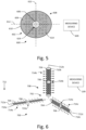
- Fig. 5 depicts a top schematic view of another exemplary embodiment of a flexible microfluidic sensor 600 according to this disclosure.
- the sensor 600 includes a flexible microfluidic structure 602, a first fluid 604 and second fluid 606 disposed within the microfluidic structure 602, an electrode arrangement 608, and a measurement device 609.
- the microfluidic structure 602 defines a microfluidic chamber 610 which, in this embodiment includes a microfluidic cavity 610 that extends over both a first axis 612 and a second axis 613 perpendicular to the first axis 612.
- the microfluidic cavity 610 has a substantially circular shape, but other shapes are also contemplated in other embodiments.
- the electrode arrangement 608 includes a set of electrode pairs 614 that are distributed circumferentially and radially over the microfluidic cavity 610. For the sake of clarity, electric connections between the electrode pairs 614 and the measuring device 609 are omitted from Fig. 5 .
- the second fluid 606 is less dense and less resistance than the first fluid 604, and forms a bubble 624 within the first fluid 604.
- a location of the bubble 624 along the first axis 612 is based on at least one of an acceleration of the microfluidic structure 602 along the first axis 612, and an orientation of the first axis 612 of the microfluidic structure 602 relative to a direction of gravity (into the page in Fig. 6 ).
- the location of the bubble 624 along the second axis 613 is based on at least one of an acceleration of the microfluidic structure 602 along the second axis 613 and an orientation of the second axis 613 of the microfluidic structure 602 relative to a direction of gravity.
- the electrode pairs 614 in the electrode arrangement 608 enable determining at least one of the orientation, acceleration, and rotation of the micro fluidic structure 602 in a manner similar to the embodiments discussed above. Due to the difference in resistance between the first fluid 604 and second fluid 606, the resistance measured across each of the electrode pairs 614 is based on a relationship between the location of the bubble 624 and the electrode pairs 614. In other words, a resistance measured across an electrode pair 414 proximate to the bubble 624 is less than a resistance measured across an electrode not proximate to the bubble 624.
- the measurement device 609 is thus configured to determine a location of the bubble 624 along both the first axis 612 and the second axis 613 based on the resistances measured across the electrode pairs 614.
- the measurement device 609 is configured to determine at least one of an acceleration of the microfluidic structure 602 along the first axis 612, and an orientation of the first axis 612 of the microfluidic structure 602 relative to a direction of gravity based on the location of the bubble 624 along the first axis 612, and to determine at least one of an acceleration of the microfluidic structure 602 along the second axis 613 and an orientation of the second axis 613 of the microfluidic structure 602 relative to a direction of gravity based on the location of the bubble 624 along the second axis 613.
- the measurement device is further configured to isolate determination of accelerations from determination of orientations by making multiple determinations over time, whereby transient locations of the bubble 624 are indicative of accelerations while static locations are indicative of orientations.
- rotation of the microfluidic structure 602 causes the microfluidic cavity 610 to flex outwards, increasing a diameter of the bubble 624 and thereby modifies a total capacitance of the electrode arrangement 608 that enables the measurement device 609 to determine the rotation of the microfluidic structure 602 about a rotation axis perpendicular to the first axis 612 and second axis 613.
- Fig. 6 depicts a perspective schematic view of another exemplary embodiment of a flexible microfluidic sensor 700 according to this disclosure.
- the sensor 700 includes a flexible microfluidic structure 702, a first fluid 704 and second fluid 706 disposed within the microfluidic structure 702, an electrode arrangement 708, and a measurement device 709.
- electric connections between the microfluidic structure 702 and the measuring device 709 are omitted in Fig. 7 .
- the microfluidic structure 702 defines a microfluidic chamber that includes a first microfluidic channel 710a that extends along a first axis 712a, a second microfluidic channel 710b that extends along a second axis 712b perpendicular to the first axis 712a, and a third microfluidic channel 710c that extends along a third axis 712c perpendicular to both the first axis 712a and the second axis 712b.
- Each of the microfluidic channels 710a-c is closed off from each other, and is respectively filled with the first fluid 704 and a bubble 724a, 724b, and 724c respectively of the second fluid 706.
- the electrode arrangement 708 includes first, second, and third sets of pairs 714a-c of electrodes that are respectively disposed along the first axis 712a, second axis 712b, and third axis 712c on opposing sides of the corresponding microfluidic channels 710a-c.
- the structure of each of the individual microfluidic channels 710a-c is similar to the structure of the microfluidic channel 110 depicted in Fig. 2a .
- the microfluidic channel 710a, electrode pairs 714a, and bubble 724a enable determining at least one of an orientation of the first axis 712a of the microfluidic structure 702 relative to gravity, an acceleration of the microfluidic structure 702 along the first axis 712a, a rotation of the microfluidic structure 702 about the second axis 712b, and a rotation about the third axis 712c.
- the microfluidic channel 710b, electrode pairs 714b, and bubble 724b enable determining at least one of an orientation of the second axis 712b of the microfluidic structure 702 relative to gravity, an acceleration of the microfluidic structure 702 along the second axis 712b, a rotation about the first axis 712a, and a rotation of the microfluidic structure 702 about the third axis 712c.
- the microfluidic channel 710c, electrode pairs 714c, and bubble 724c enable determining at least one of an orientation of the third axis 712c of the microfluidic structure 702 relative to gravity, an acceleration of the microfluidic structure 702 along the third axis 712c, a rotation of the microfluidic structure 702 about the first axis 712a and a rotation about the second axis 712b.
- the measurement device 709 is configured to use determinations of at least one of orientation, acceleration, and rotation relative to multiple axes in order to improve an accuracy of at least one other determination.
- motion of the bubble 724a along the first axis 712a can result from an acceleration along the first axis 712a, a rotation about the second axis 712b, a rotation about the third axis 712c, or a combination thereof.
- the measurement device 709 is configured to use a determination of a rotation of the microfluidic structure 702 about the second axis 712b based on the microfluidic channel 710c, electrode pairs 714c, and bubble 724c to isolate a determination of an acceleration along the first axis 712a based on the microfluidic channel 710a, electrode pairs 714a, and bubble 724a from a determination of a rotation about the second axis 712b based on the microfluidic channel 710a, electrode pairs 714a, and bubble 724a.
- Fig. 7 is a functional block diagram of an exemplary embodiment of a flexible electronic device 800 according to this disclosure.
- the device 800 includes at least one flexible electronic circuit 870 and a flexible microfluidic sensor 801.
- inertial sensors for sensing orientation, acceleration, and rotation are generally formed on silicon platforms in conformance with mass manufacturing processes inherited from the semiconductor industry. While silicon-based sensors are generally fast-acting and highly accurate, the silicon base results in a heterogeneous integration with the more flexible material of a flexible circuit. The more rigid silicon not only can create bending creases and stress points that can lead to damage of the device, but can also decrease the overall flexibility of the device.
- the flexibility of the sensor 802 enables homogeneous integration of the sensor 801 with the flexible circuit 807.
- the flexible circuit 870 includes a circuit printed on or encased in a flexible polymer, and the sensor 801 includes a microfluidic structure formed with the flexible polymer.
- a sensor according to this disclosure may be less rapidly responsive than a conventional silicon-based inertial sensor.
- fluid-based determinations may be less accurate than the highly precise measurements made possible by extremely sensitive silicon-based sensors.
- many applications for flexible electronic devices are more limited by the flexibility of the device than by the precision or rapidity of the measurements.
- Fig. 8 depicts another exemplary embodiment of a flexible electronic device 900 according to this disclosure.
- the device 900 has a microfluidic sensor, such as one of the embodiments of a sensor discussed above.
- the sensor is configured to sense an acceleration of at least a portion of a user 990 in the direction of gravity 911.
- the device 900 further has a flexible electronic circuit configured to determine that the sensed acceleration indicates that the user has taken a step, and count a total of steps taken by the user.
- an electronic device is configured to determine that at least one rotation, acceleration, and orientation corresponds to a specific motion of a user.
- a flexible electronic device according to this disclosure is integrated into a flexible wristband, and is configured to determine that a user is, for example, swinging a tennis racket or golf club, throwing a ball, or the like.
Landscapes
- Chemical & Material Sciences (AREA)
- Health & Medical Sciences (AREA)
- Physics & Mathematics (AREA)
- General Physics & Mathematics (AREA)
- General Health & Medical Sciences (AREA)
- Chemical Kinetics & Catalysis (AREA)
- Analytical Chemistry (AREA)
- Engineering & Computer Science (AREA)
- Radar, Positioning & Navigation (AREA)
- Hematology (AREA)
- Clinical Laboratory Science (AREA)
- Remote Sensing (AREA)
- Dispersion Chemistry (AREA)
- Life Sciences & Earth Sciences (AREA)
- Pathology (AREA)
- Immunology (AREA)
- Biochemistry (AREA)
- Electrochemistry (AREA)
- Heart & Thoracic Surgery (AREA)
- Molecular Biology (AREA)
- Oral & Maxillofacial Surgery (AREA)
- Biophysics (AREA)
- Biomedical Technology (AREA)
- Physiology (AREA)
- Medical Informatics (AREA)
- Dentistry (AREA)
- Surgery (AREA)
- Animal Behavior & Ethology (AREA)
- Public Health (AREA)
- Veterinary Medicine (AREA)
- Investigating Or Analyzing Materials By The Use Of Electric Means (AREA)
- Pressure Sensors (AREA)
- Micromachines (AREA)
Description
- The present invention relates to a flexible microfluidic motion sensor for sensing at least one of orientation, acceleration and rotation and to a flexible electronic device.
-
US2016/025535 A1 discloses a microfluidic flow rate sensor comprising a microfluidic structure that defines at least one microfluidic chamber, a first material and a second material disposed in the at least one chamber, the second material having at least one physical property that is different than a physical property of the first material, and the second material having at least one electronic property that is different than an electronic property of the first material, an electrode arrangement including at least of pair of electrodes that are spaced apart from each other with at least a portion of the at least one chamber located functionally directly between the electrodes such that one electronic property measured across the at least one pair of electrodes is based on a relationship between the second material and the at least one pair of electrodes, wherein the relationship between the second material and the at least one pair of electrodes is based on a physical condition of the microfluidic structure. - Maximilian Focke et.al., "Lab-on-a-Foil: microfluidics on thin and flexible films", LAB ON A CHIP, (20100319), vol. 10, No. 11, ISSN 1473-0197 discloses fabrication processes and approaches for the integration of microfluidic functions on thin and flexible film.
-
US 2016/025535 A1 ,KR 100 969 579 B1US 4 676 103 A andUS 3 530 726 A disclose microfluidic accelerometers comprising a microfluidic channel , at least one pair of electrodes situated either side of the channel, and a movable substance inside the channel. - Continuing development toward wearable devices and the internet-of-things has motivated the development of flexible electronics. Customarily, electronics were formed on rigid silicon platforms that were not well adapted to these uses. To address this issue, flexible electronics have been developed that are formed on flexible polymer-based platforms. One difficulty encountered with the use of flexible polymer-based platforms is the integration of motion sensors.
- Motion sensors, including accelerometers and gyroscopes, are used in a wide variety of applications, and generally include a structure formed onto a silicon platform. As a result, current solutions provide a heterogeneous integration of silicon-based sensors with polymer-based electronics. The silicon sensors decrease the flexibility of the resulting device, and flexure of the device can negatively impact the performance of the sensors. Additionally, since the sensors and electronics are made using different platforms, manufacturing such heterogeneous devices becomes increasingly complex, costly, and time-consuming. Based on the foregoing, a motion sensor that is flexible would be beneficial. A motion sensor that can be formed homogeneously with flexible electronics would also be beneficial. Summary
- A flexible microfluidic sensor according to this invention is defined in
independent claims 1 and 10. - In some embodiments, the second material is a second fluid. In some embodiments, the second fluid includes at least one of a liquid and a gas.
- In some embodiments, the second material includes a solid. In some embodiments, the second material consists of a solid. In some embodiments, the second material includes a fluid disposed within a solid shell.
- In some embodiments, the at least one physical property includes at least one of density and viscosity.
- In some embodiments, the at least one electrical property measured across the at least one pair of electrodes includes at least one of resistance and capacitance.
- According to one aspect of the invention, the at least one chamber includes a first microfluidic channel that extends along a first axis. The second fluid forms a first bubble within the first fluid in the first microfluidic channel. The at least one pair of electrodes includes a first set of electrode pairs distributed along the first axis of the first microfluidic channel such that at least one electronic property measured across the first set of electrode pairs is based on a relationship between the first bubble and the first set of electrode pairs. The relationship between the first bubble and the first set of electrode pairs is based on at least one of an orientation of the first axis relative to a direction of gravity, an acceleration of the microfluidic structure along the first axis, and a rotation of the microfluidic structure perpendicular to the first axis.
- In some embodiments, the relationship between the first bubble and the first set of electrode pairs includes at least one of a location of the first bubble along the first axis and a diameter of the first bubble.
- In some embodiments, each electrode in the first set of electrode pairs includes a respective electrical contact.
- In some embodiments, the sensor includes a measurement device electrically connected to the electrical contacts of the electrodes in the first set of electrode pairs. The measurement device is configured to determine the relationship between the first bubble and the first set of electrode pairs based on the at least one electrical property measured across the first set of electrode pairs distributed along the first axis, and to determine, based on the determined relationship, a physical condition of the microfluidic structure.
- In some embodiments, each electrode pair in the first set of electrode pairs has a respective resistive load so that the resistive load of the first set of electrode pairs varies along the first axis. The at least one electrical property measured across the first set of electrode pairs includes resistance, such that a total resistance of the first set of electrode pairs changes based on the location of the first bubble along the first microfluidic channel. The measurement device is further configured to determine the location of the first bubble along the first microfluidic channel based on the total resistance of the first set of electrode pairs.
- In some embodiments, the at least one chamber includes a second microfluidic channel that extends along a second axis extending perpendicularly to the first axis. The second fluid forms a second bubble within the first fluid in the second microfluidic channel. The at least one pair of electrodes includes a second set of electrode pairs distributed along the second axis of the second microfluidic channel such that at least one electronic property measured across the second set of electrode pairs is based on a relationship between the second bubble and the second set of electrode pairs. The relationship between the second bubble and the second set of electrode pairs is based on at least one of an orientation of the second axis relative to the direction of gravity, an acceleration of the microfluidic structure along the second axis, and a rotation of the microfluidic structure perpendicular to the second axis.
- In some embodiments, the at least one chamber includes a third microfluidic channel that extends along a third axis extending perpendicularly to the first axis and perpendicularly to the second axis. The second fluid forms a third bubble within the first fluid in the third microfluidic channel. The at least one pair of electrodes includes a third set of electrode pairs distributed along the third axis of the second microfluidic channel such that at least one electronic property measured across the third set of electrode pairs is based on a relationship between the third bubble and the third set of electrode pairs. The relationship between the third bubble and the third set of electrode pairs is based on at least one of an orientation of the third axis relative to the direction of gravity, an acceleration of the microfluidic structure along the third axis, and a rotation of the microfluidic structure perpendicular to the third axis.
- According to another aspect of the invention, the at least one chamber includes a microfluidic cavity that extends along a first axis and along a second axis perpendicular to the first axis. The second fluid forms a bubble within the first fluid in the microfluidic cavity. The at least one electronic property measured across the at least one pair of electrodes is based on a relationship between the bubble and the at least one pair of electrodes. The physical condition of the microfluidic structure includes at least one of an acceleration of the microfluidic structure along the first axis, an acceleration of the microfluidic structure along the second axis, an orientation of the second axis relative to a direction of gravity, an orientation of the first axis relative to the direction of gravity, and a rotation of the microfluidic structure about a third axis perpendicular to the first axis and the second axis.
- In some embodiments, the microfluidic cavity has a first diameter, and is configured to flex due to rotation of the microfluidic structure about the third axis such that the first diameter increases. The at least one bubble has a second diameter that is based on the first diameter, such that the second diameter is based on the rotation of the microfluidic structure about the third axis.
- In some embodiments, the at least one electronic property measured across the at least one pair of electrodes includes capacitance. The at least one electronic property of the second fluid includes dielectric permittivity such that the capacitance measured across at least one electrode pair changes based on the second diameter of the at least one bubble.
- In some embodiments, the sensor includes a measurement device electrically connected to the at least one electrode pair and configured to determine the rotation rate of the microfluidic structure based on the capacitance measured across the at least one electrode pair.
- In some embodiments, the microfluidic structure consists of flexible polymer material.
- In some embodiments, the flexible polymer material includes at least one of poly-dimethyle-siloxane and Parylene.
- A flexible electronic device according to the invention is defined in independent claim 17.
-
-
Fig. 1a is a top plan view of an exemplary embodiment of a flexible microfluidic sensor according to this disclosure. -
Fig. 1b is a side plan view of the sensor fromFig. 1a in a first orientation. -
Fig. 1c is a side plan view of the sensor fromFig. 1a in a second orientation. -
Fig. 2a is a top plan view of another exemplary embodiment of a flexible microfluidic sensor according to this disclosure. -
Fig. 2b is a top plan view of the sensor fromFig. 2a subject to an acceleration. -
Fig. 3 is a side plan view of another exemplary embodiment of a flexible microfluidic sensor according to this disclosure. -
Fig. 4 is a side plan view of the sensor fromFig. 3 subject to a nonzero rotation rate. -
Fig. 5 is a top plan view of another exemplary embodiment of a flexible microfluidic sensor according to this disclosure. -
Fig. 6 is a perspective plan view of another exemplary embodiment of a flexible microfluidic sensor according to this disclosure. -
Fig. 7 is a functional block diagram of an exemplary embodiment of a flexible electronic device according to this disclosure. -
Fig. 8 is an illustration of an exemplary embodiment of a flexible electronic device according to this disclosure in use on a wrist of a user. - For the purposes of promoting an understanding of the principles of the embodiments described herein, reference is now made to the drawings and descriptions in the following written specification. The invention is defined by the appended claims.
-
Fig. 1a depicts a top plan view of an exemplary embodiment of a flexiblemicrofluidic sensor 100 according to this disclosure, andFig. 1b depicts a side plan view of thesensor 100. Thesensor 100 includes amicrofluidic structure 102, afirst material 104, asecond material 106, anelectrode arrangement 108, and ameasurement device 109. - The
microfluidic structure 102 defines amicrofluidic chamber 110. In this embodiment, themicrofluidic chamber 110 is amicrofluidic channel 110 that extends along afirst axis 112. As depicted inFig. 1b , in this embodiment thefirst axis 112 is curved relative to a direction ofgravity 111, and thus themicrofluidic channel 110 has a curved shape when viewed from the side. In other embodiments, theaxis 112 andmicrofluidic channel 110 have other shapes. - The
microfluidic channel 110 is formed from a flexible material. In one example, the flexible material is a polymer, such as poly-dimethyle-siloxane, Parylene, or derivatives or combinations thereof. In this embodiment, themicrofluidic channel 110 is closed. In other embodiments, the microfluidic channel is at least partially open. In some embodiments, a membrane at least partially covers an opening in the micro fluidic channel. - At least one of the
first material 104 and thesecond material 106 is a fluid. As used herein, a "fluid" means a material having the capability to flow, and can include a liquid, a gas, a collection of flowable solid particles, or combinations thereof. In this embodiment, thefirst material 104 is a first fluid, and thesecond material 106 is a second fluid. In other embodiments, other materials or combinations of materials are used. Thefirst fluid 104 andsecond fluid 106 are disposed within themicrofluidic channel 110. Thesecond fluid 106 has at least one physical property that is different than a physical property of thefirst fluid 104, and at least one electronic property that is different than an electronic property of thefirst fluid 104. Specifically, in this embodiment, thefirst fluid 104 andsecond fluid 106 have different densities and different resistances. Fluids of different densities will gradually stratify into separate regions arranged in order of increasing density relative to a direction of gravity. More dense materials, having more mass per unit volume, also experience more inertia relative to less dense materials due to, for example, an acceleration or rotation. - In this embodiment, the
first fluid 104 has a higher density than thesecond fluid 106. In other embodiments, thefirst fluid 104 has a lower density than thesecond fluid 106. Due to the difference in density, thesecond fluid 106 forms abubble 124 within thefirst fluid 104. As used herein, the term "bubble" means a globule of material that is at least substantially unmixed with other surrounding material. - The
first fluid 104 andsecond fluid 106 can include any acceptable material or combination of materials. In some embodiments, thefirst fluid 104 andsecond fluid 106 are liquids. In some embodiments, at least one of thefirst fluid 104 andsecond fluid 106 is a gas. - The
electrode arrangement 108, in this embodiment, includes a set of electrode pairs 114 distributed along thefirst axis 112. In this embodiment, the first set 114 includes threepairs 114a-c, but other numbers of pairs are included in other embodiments. For example, some embodiments include only a single pair, while other embodiments include ten, one hundred, or one thousand pairs, or more. - Each
electrode pair 114a-c respectively includeselectrodes channel 110 located functionally directly therebetween. As used herein, the phrase "functionally directly therebetween" means "located so as to have an influence on the operation or interaction thereof." In other words, theelectrodes pair 114a-c are configured to interact with each other through the at least portion of themicrofluidic channel 110 such that the interaction is influenced by the portion of thechannel 110 therebetween. In this embodiment, with thefirst fluid 104 andsecond fluid 106 having different resistances, the interaction between theelectrodes electrodes channel 110 functionally directly therebetween. Other types of interactions are also contemplated in other embodiments. - The
electrodes electrodes opposite sides microfluidic channel 110. Other location for theelectrodes - Each
pair 114a-c enables the detection of a presence of thebubble 124 in a region near that pair due to the difference in resistance in thefirst fluid 104 andsecond fluid 106. In other words, due to the difference in resistance between thefirst fluid 104 andsecond fluid 106, the resistance measured across theelectrodes bubble 124 or thefirst fluid 104 is located functionally therebetween, and that difference is indicative of the presence of thebubble 124. - Each of the
electrodes electrical contact 126 connected with themeasurement device 109. In this embodiment, theelectrical contacts 126 are connected via separate connections with themeasurement device 109. In other embodiments, other connection types are also contemplated, such as all of the contacts being connected to themeasuring device 109 in parallel. - The measuring
device 109 is configured to determine a relationship between thesecond fluid 106 and theelectrode arrangement 108, in this embodiment a location of thebubble 124 along thefirst axis 112, and is further configured to determine a physical condition of the microfluidic structure based on the determined location. As used herein a "physical condition" means at least one of an orientation relative to a direction of gravity, an acceleration along one or more axes, and a rotation about one or more axes. - The measuring
device 109 is configured to determine location of thebubble 124 based on the difference in the interactions of the electrode pairs 114. Specifically, in this embodiment, the measuringdevice 109 is configured to determine a location of thebubble 124 based on resistances measured across the electrode pairs 114a-c. InFig. 1b , thebubble 124 is proximate to thepair 114b. Thus, the resistance measured acrosspair 114b is based on the resistance of thesecond fluid 106, while the resistance measured across thepairs first fluid 104. Based on the foregoing, the measuringdevice 109 is configured to determine that thebubble 104 is located proximate to thepair 114b. - The determined location of the
bubble 124 enables the measuringdevice 109 to determine the physical condition of themicrofluidic structure 102 because the difference in physical properties between thefirst fluid 104 andsecond fluid 106 cause thefirst fluid 104 andsecond fluid 106 respond differently to the physical condition of themicrofluidic structure 102, and in particular to the orientation of thefirs axis 112 of themicrofluidic structure 102 relative to the direction ofgravity 111. - Specifically, since the
second fluid 106 is less dense than thefirst fluid 104, thebubble 124 is located at a highest point in the microfluidic channel 110 relative togravity 111. InFig. 1b , the highest point relative togravity 111 is proximate to thepair 114b. InFig. 1c , themicrofluidic structure 102 has been reoriented so that theaxis 112 is at an angle relative togravity 111. InFig. 1c , the highest point relative togravity 111 is proximate to thepair 114c, and thus thebubble 124 has been relocated along thefirst axis 112 so as to be proximate to thepair 114c. In other words, a relationship between thesecond fluid 106 and the electrode pairs 114 is based on the physical condition of themicrofluidic structure 102, and moreover is detectable via themeasuring device 109 due to the difference in resistance between thefirst fluid 104 andsecond fluid 106. - In another embodiment of a flexible microfluidic sensor according to this disclosure, the sensor is structured similarly to the
sensor 100 depicted inFigs. 1a and 1b . In this embodiment, thesecond fluid 106 has a higher dielectric permittivity than thefirst fluid 104. A capacitance measured across two electrodes separated by a gap increases with an increased dielectric permittivity in the space therebetween. Thus, in this embodiment, themeasurement device 109 is configured to determine the location of thebubble 124 based on capacitances measured across the electrode pairs 114a-c. - In another embodiment of a flexible microfluidic sensor according to this disclosure, the sensor is structured similarly to the
sensor 100 depicted inFigs. 1a and 1b . In this embodiment, the second material is a solid ball. In some embodiments, thesolid ball 106 consists of solid material. In other embodiments, the solid ball includes a solid shell filled with fluidic material. The solid shell enables the selection of fluids having desirable physical properties that would otherwise mix or be incompatible with the first fluid. The solid ball behaves similarly to a bubble within the first fluid with regard to the interactions across electrodes and with movement along the microfluidic channel. - In another embodiment of a flexible microfluidic sensor according to this disclosure, the sensor is structured similarly to the
sensor 100 depicted inFigs. 1a and 1b . In this embodiment, the first material is a porous solid material. In some embodiments, the first material is a contiguous material. In some embodiments, the first material includes discrete grains. The second material is a fluid that is able to flow within the porous first material and form a collection within the first material that behaves similarly to a bubble. -
Fig. 2a depicts a top plan view of another exemplary embodiment of a flexiblemicrofluidic sensor 200 according to this disclosure. Thesensor 200 includes amicrofluidic structure 202 that includes achannel 210, afirst fluid 204, asecond fluid 206, anelectrode arrangement 208, and ameasurement device 209. Thesecond fluid 206 has a different resistance and a different viscosity than thefirst fluid 204. Specifically, in this embodiment, the second fluid has a lower resistance and a lower viscosity than thefirst fluid 204. Thesecond fluid 206 forms abubble 224 within thefirst fluid 204. - The
electrode arrangement 208 includes a set of tenelectrode pairs 214a-j that each includeselectrodes sides microfluidic channel 210. In this embodiment, each of theelectronic contacts 226 for thepairs 214a-j is connected to themeasurement device 209 in parallel. Further, in this embodiment, each of thepairs 214a-j has a respective resistive load such that the resistive load of thepairs 214a-j varies along thefirst axis 212. Due to the variance in the resistive loads, and to the difference in resistance between thefirst fluid 204 andsecond fluid 206, a total resistance of the electrode pairs 214a-j varies based on a location of thebubble 224 along thefirst axis 212. - The
first fluid 204 acts like an open circuit connection when located functionally directly between an electrode pair due to its relatively high resistance. Conversely, thesecond fluid 206 acts like a closed circuit connected when located functionally directly between an electrode pair due to its relatively low resistance. As a result, the total resistance of thepairs 114a-j is substantially based on the resistive load of the pair 214e proximate to thebubble 224. Themeasurement device 209 is thus able to determine the location of thebubble 224 based on the total resistance of thepairs 214a-j, which inFig. 2a is proximate to the pair 214-e. - Due to the difference in viscosity, the
first fluid 204 andsecond fluid 206 respond differently to an acceleration of themicrofluidic structure 202. InFig. 2b , themicrofluidic structure 202 has been accelerated in adirection 215 substantially along thefirst axis 212. Since thefirst fluid 204 has a higher viscosity than thesecond fluid 206, thefirst fluid 204 is more resistant to flow, and is thus more resistant to forces caused by the acceleration. As a result, at least a portion of thefirst fluid 204 moves relative to thebubble 224 counter to thedirection 215 of the acceleration, such that thebubble 224 is moved along thefirst axis 215 in the direction of theacceleration 215. The magnitude of the movement of the bubble corresponds to the magnitude of the acceleration. - In
Fig. 2b , the bubble has been moved so as to be proximate to thepair 214c. Thus, as a result of the movement of thebubble 224, the total resistance of thepairs 114a-j inFig. 2b is substantially based on the resistive load of thepair 214c instead of the pair 241e as inFig. 2a . Themeasurement device 209 is configured to determine a magnitude of the motion of thebubble 224 along thefirst axis 212, and is further configured to determine a physical condition of themicrofluidic structure 202 based on the determined magnitude. To determine the magnitude, the measuringdevice 209 is configured to determine that the location of thebubble 224 has changed, and compare an initial location of thebubble 224 with the new changed location. - In another embodiment of a flexible microfluidic sensor according to this disclosure, the sensor has a similar configuration to the
sensor 200 depicted inFigs. 2a and 2b . In this embodiment, thesecond fluid 206 has a lower density that thefirst fluid 204. Due to the difference in density, thesecond fluid 206 has less inertia than thefirst fluid 204, which causes thefirst fluid 204 andsecond fluid 206 to respond differently to an acceleration of themicrofluidic structure 202. In particular, thebubble 224 of thesecond fluid 206 is less resistant to motion than thefirst fluid 204, and thus at least a portion of the first fluid moves past thebubble 224 in a direction opposite theacceleration 215 so that thebubble 224 moves along thefirst axis 212 in the direction of the acceleration. -
Fig. 3 depicts a side plan view of another exemplary embodiment of a flexiblemicrofluidic sensor 400 according to this disclosure. Thesensor 400 includes a flexible microfluidic structure 402, afirst fluid 404 andsecond fluid 406 disposed within themicrofluidic structure 402, anelectrode arrangement 408, and ameasurement device 409. - The
microfluidic structure 402 defines a micro fluidic chamber that, in this embodiment, includes amicrofluidic cavity 410 having afirst diameter 450. Themicrofluidic cavity 410 is configured to flex based on a rotation rate of themicrofluidic structure 402 about arotation axis 452 perpendicular to thefirst diameter 450 such that thefirst diameter 450 increases due to the rotation. - The
second fluid 406 has a lower density than thefirst fluid 404. In some embodiments, thesecond fluid 406 is a gas, such as air. Thesecond fluid 406 forms abubble 424 within thefirst fluid 404 having asecond diameter 454. An increase in thefirst diameter 450 increases a capacity of thecavity 410, such that thesecond diameter 454 is based on thefirst diameter 450 of themicrofluidic cavity 410. In other words, thesecond diameter 454 of thebubble 424 is configured to increase as thefirst diameter 450 of themicrofluidic cavity 410 increases due to rotation about therotation axis 452. - The
electrode arrangement 408 includes apair 414 ofelectrodes microfluidic cavity 410 and are configured to interact through themicrofluidic cavity 410. Thesecond fluid 406 has a higher dielectric permittivity than thefirst fluid 404. As a result, a capacitance measured across theelectrode pair 414 increases with an increase in thesecond diameter 454. Thus, the capacitance measured across theelectrode pair 414 is indicative of the rotation rate of themicrofluidic structure 402 about therotation axis 452. The measuringdevice 409 is configured to determine the second diameter of thebubble 424 based on the capacitance measured across theelectrode pair 414, and to determine the rotation rate of themicrofluidic structure 402 based on the determinedsecond diameter 454. - In
Fig. 3 , the rotation rate of themicrofluidic structure 402 is zero.Fig. 4 depicts themicrofluidic structure 402 with a nonzero rotation rate about therotation axis 452. Due to the higher density of thefirst fluid 404 relative to thesecond fluid 406, thefirst fluid 404 has a higher inertia relative to thesecond fluid 406. As a result, the rotation of themicrofluidic structure 402 about therotation axis 452 biases thefirst fluid 404 away from therotation axis 452 and pushes thefirst fluid 404 againstinner sidewalls microfluidic cavity 410 that are at least substantially perpendicular to thefirst diameter 450. A force of thefirst fluid 404 against theinner sidewalls microfluidic structure 402 to flex and increases thefirst diameter 450 of themicrofluidic cavity 410 inFig. 4 relative to the diameter depicted inFig. 3 . Since thesecond diameter 454 of thesecond fluid 406 is based on thefirst diameter 450, thesecond diameter 454 in the rotatingmicrofluidic structure 402 inFig. 4 is larger than the diameter depicted inFig. 3 . - In another embodiment of a flexible microfluidic sensor according to this disclosure, the sensor has a structure similar to the
sensor 400 depicted inFigs. 3 and 4 , and the resistance of thefirst fluid 404 is higher than the resistance of thesecond fluid 406. Due to the difference in resistances, an increase in thesecond diameter 454 of thebubble 424 of thesecond fluid 406 decreases a total resistance across theelectrodes device 409, in this embodiment, is configured to determinesecond diameter 454 of thebubble 424 based on the resistance measured across theelectrode pair 414, and to determine the rotation rate of themicrofluidic structure 402 based on the determined resistance. - While the embodiments depicted in
Figs. 1-4 and described above disclose using particular physical and electrical properties, other embodiments use other properties or combinations of properties. Further, in some embodiments, the first fluid has multiple different physical or electronic properties from the second fluid that are used to determine the physical condition of a microfluidic structure. In one embodiment, a resistance measured across an electrode arrangement that persists beyond a predetermined period of time is used to determine a static orientation of a microfluidic structure, a change in total resistance across the electrode arrangement is used to determine an acceleration of the microfluidic structure, and a change in capacitance across the electrode arrangement is used to determine a rotation of the microfluidic structure. - Additionally, while the
measurement devices sensors - As noted above, each of a reorientation, acceleration, and rotation of a microfluidic structure in the embodiments above affects the arrangement of the first and second fluids. In some instances, a similar arrangement of the fluids can result from different actions. For example, an acceleration along a first axis of a microfluidic structure can cause a bubble of the second fluid to move to a new first location, and a reorientation of the microfluidic structure can also cause the bubble to move to the same first location. Thus, given only a previous location and a new location of the bubble, it may be at least partially indeterminate whether the change in location resulted from a reorientation, an acceleration, or a rotation, or some combination thereof. As discussed below, it is possible to isolate orientation, acceleration, and rotation from each other via several different techniques.
- In one embodiment, a microfluidic device according to this disclosure includes a first microfluidic sensor configured as a dedicated tilt sensor, and a second microfluidic sensor configured as at least one of an acceleration sensor and rotation sensor. A measuring device associated with the microfluidic device is configured to use the tilt sensor to determine a reference frame for the acceleration or rotation sensor, and thereby decouple the orientation of the microfluidic device from rotation and acceleration.
- In another embodiment, a measurement device is configured to make a determination of at least one of orientation, acceleration, and rotation based on a set of successive values of an electrode arrangement taken over time. Specifically, a time period over which a microfluidic structure is subjected to an acceleration or rotation is generally short relative to a time period over which the microfluidic is maintained in a substantially static orientation. Thus, taking a set of successive values of an electrode arrangement over time, enables differentiating between relatively transient values associated with an acceleration and relatively static values associated with an orientation.
- In a further embodiment, values of a set of different electrical properties are taken from an electrode arrangement. In one example, the capacitance of individual electrode pairs is used to determine a location of a bubble along a microfluidic channel indicative of acceleration or orientation, and a total capacitance of the entire electrode arrangement is used to determine a rotation rate. A measurement device is configured to use the rotation rate to define a reference frame for the microfluidic structure, and thereby decouple the rotation of the microfluidic device from acceleration and orientation.
- In another embodiment, the actions of reorientation, acceleration, and rotation are decoupled by taking values of multiple different electrode arrangements that are respectively aligned with different axes, as discussed in more detail below.
-
Fig. 5 depicts a top schematic view of another exemplary embodiment of a flexiblemicrofluidic sensor 600 according to this disclosure. Thesensor 600 includes a flexiblemicrofluidic structure 602, afirst fluid 604 andsecond fluid 606 disposed within themicrofluidic structure 602, anelectrode arrangement 608, and ameasurement device 609. - The
microfluidic structure 602 defines amicrofluidic chamber 610 which, in this embodiment includes amicrofluidic cavity 610 that extends over both afirst axis 612 and asecond axis 613 perpendicular to thefirst axis 612. In this embodiment, themicrofluidic cavity 610 has a substantially circular shape, but other shapes are also contemplated in other embodiments. - The
electrode arrangement 608 includes a set of electrode pairs 614 that are distributed circumferentially and radially over themicrofluidic cavity 610. For the sake of clarity, electric connections between the electrode pairs 614 and the measuringdevice 609 are omitted fromFig. 5 . - In this embodiment, the
second fluid 606 is less dense and less resistance than thefirst fluid 604, and forms abubble 624 within thefirst fluid 604. A location of thebubble 624 along thefirst axis 612 is based on at least one of an acceleration of themicrofluidic structure 602 along thefirst axis 612, and an orientation of thefirst axis 612 of themicrofluidic structure 602 relative to a direction of gravity (into the page inFig. 6 ). Similarly, the location of thebubble 624 along thesecond axis 613 is based on at least one of an acceleration of themicrofluidic structure 602 along thesecond axis 613 and an orientation of thesecond axis 613 of themicrofluidic structure 602 relative to a direction of gravity. - The electrode pairs 614 in the
electrode arrangement 608 enable determining at least one of the orientation, acceleration, and rotation of themicro fluidic structure 602 in a manner similar to the embodiments discussed above. Due to the difference in resistance between thefirst fluid 604 andsecond fluid 606, the resistance measured across each of the electrode pairs 614 is based on a relationship between the location of thebubble 624 and the electrode pairs 614. In other words, a resistance measured across anelectrode pair 414 proximate to thebubble 624 is less than a resistance measured across an electrode not proximate to thebubble 624. Since the electrode pairs 614 are distributed across both thefirst axis 612 and thesecond axis 613, determining that thebubble 224 is proximate to aparticular electrode pair 414 is indicative of a location of thebubble 624 along each of thefirst axis 612 and thesecond axis 613. Themeasurement device 609 is thus configured to determine a location of thebubble 624 along both thefirst axis 612 and thesecond axis 613 based on the resistances measured across the electrode pairs 614. Further, themeasurement device 609 is configured to determine at least one of an acceleration of themicrofluidic structure 602 along thefirst axis 612, and an orientation of thefirst axis 612 of themicrofluidic structure 602 relative to a direction of gravity based on the location of thebubble 624 along thefirst axis 612, and to determine at least one of an acceleration of themicrofluidic structure 602 along thesecond axis 613 and an orientation of thesecond axis 613 of themicrofluidic structure 602 relative to a direction of gravity based on the location of thebubble 624 along thesecond axis 613. - Additionally, as noted above, in some embodiments, the measurement device is further configured to isolate determination of accelerations from determination of orientations by making multiple determinations over time, whereby transient locations of the
bubble 624 are indicative of accelerations while static locations are indicative of orientations. - In another embodiment, rotation of the
microfluidic structure 602 causes themicrofluidic cavity 610 to flex outwards, increasing a diameter of thebubble 624 and thereby modifies a total capacitance of theelectrode arrangement 608 that enables themeasurement device 609 to determine the rotation of themicrofluidic structure 602 about a rotation axis perpendicular to thefirst axis 612 andsecond axis 613. -
Fig. 6 depicts a perspective schematic view of another exemplary embodiment of a flexiblemicrofluidic sensor 700 according to this disclosure. Thesensor 700 includes a flexiblemicrofluidic structure 702, afirst fluid 704 andsecond fluid 706 disposed within themicrofluidic structure 702, anelectrode arrangement 708, and a measurement device 709. For the sake of clarity, electric connections between themicrofluidic structure 702 and the measuring device 709 are omitted inFig. 7 . - In this embodiment, the
microfluidic structure 702 defines a microfluidic chamber that includes a firstmicrofluidic channel 710a that extends along afirst axis 712a, a secondmicrofluidic channel 710b that extends along asecond axis 712b perpendicular to thefirst axis 712a, and a thirdmicrofluidic channel 710c that extends along athird axis 712c perpendicular to both thefirst axis 712a and thesecond axis 712b. Each of themicrofluidic channels 710a-c is closed off from each other, and is respectively filled with thefirst fluid 704 and abubble second fluid 706. - The
electrode arrangement 708 includes first, second, and third sets ofpairs 714a-c of electrodes that are respectively disposed along thefirst axis 712a,second axis 712b, andthird axis 712c on opposing sides of the correspondingmicrofluidic channels 710a-c. Thus, the structure of each of the individualmicrofluidic channels 710a-c is similar to the structure of themicrofluidic channel 110 depicted inFig. 2a . Themicrofluidic channel 710a,electrode pairs 714a, andbubble 724a enable determining at least one of an orientation of thefirst axis 712a of themicrofluidic structure 702 relative to gravity, an acceleration of themicrofluidic structure 702 along thefirst axis 712a, a rotation of themicrofluidic structure 702 about thesecond axis 712b, and a rotation about thethird axis 712c. Themicrofluidic channel 710b, electrode pairs 714b, andbubble 724b enable determining at least one of an orientation of thesecond axis 712b of themicrofluidic structure 702 relative to gravity, an acceleration of themicrofluidic structure 702 along thesecond axis 712b, a rotation about thefirst axis 712a, and a rotation of themicrofluidic structure 702 about thethird axis 712c. Themicrofluidic channel 710c, electrode pairs 714c, andbubble 724c enable determining at least one of an orientation of thethird axis 712c of themicrofluidic structure 702 relative to gravity, an acceleration of themicrofluidic structure 702 along thethird axis 712c, a rotation of themicrofluidic structure 702 about thefirst axis 712a and a rotation about thesecond axis 712b. - In some embodiments, the measurement device 709 is configured to use determinations of at least one of orientation, acceleration, and rotation relative to multiple axes in order to improve an accuracy of at least one other determination. For example, motion of the
bubble 724a along thefirst axis 712a can result from an acceleration along thefirst axis 712a, a rotation about thesecond axis 712b, a rotation about thethird axis 712c, or a combination thereof. In one embodiment, the measurement device 709 is configured to use a determination of a rotation of themicrofluidic structure 702 about thesecond axis 712b based on themicrofluidic channel 710c, electrode pairs 714c, andbubble 724c to isolate a determination of an acceleration along thefirst axis 712a based on themicrofluidic channel 710a,electrode pairs 714a, andbubble 724a from a determination of a rotation about thesecond axis 712b based on themicrofluidic channel 710a,electrode pairs 714a, andbubble 724a. -
Fig. 7 is a functional block diagram of an exemplary embodiment of a flexibleelectronic device 800 according to this disclosure. Thedevice 800 includes at least one flexibleelectronic circuit 870 and a flexiblemicrofluidic sensor 801. - In conventional flexible electronic devices, inertial sensors for sensing orientation, acceleration, and rotation are generally formed on silicon platforms in conformance with mass manufacturing processes inherited from the semiconductor industry. While silicon-based sensors are generally fast-acting and highly accurate, the silicon base results in a heterogeneous integration with the more flexible material of a flexible circuit. The more rigid silicon not only can create bending creases and stress points that can lead to damage of the device, but can also decrease the overall flexibility of the device.
- In comparison, the flexibility of the sensor 802 enables homogeneous integration of the
sensor 801 with the flexible circuit 807. In one embodiment, theflexible circuit 870 includes a circuit printed on or encased in a flexible polymer, and thesensor 801 includes a microfluidic structure formed with the flexible polymer. - The rearrangement of fluids due to a reorientation, acceleration, or rotation is generally slow relative to the highly responsive electromechanical interactions used by silicon-based micro-electromechanical (MEMS) devices. As a result, a sensor according to this disclosure may be less rapidly responsive than a conventional silicon-based inertial sensor. Further, fluid-based determinations may be less accurate than the highly precise measurements made possible by extremely sensitive silicon-based sensors. However, many applications for flexible electronic devices are more limited by the flexibility of the device than by the precision or rapidity of the measurements.
- For example, many applications for flexible electronic devices include responding to human motion. Human motion generally occurs on a time scale far slower than the typical response time of a silicon-based sensor. Further, in many applications, high precision in sensor results is unnecessary.
-
Fig. 8 depicts another exemplary embodiment of a flexibleelectronic device 900 according to this disclosure. Thedevice 900 has a microfluidic sensor, such as one of the embodiments of a sensor discussed above. The sensor is configured to sense an acceleration of at least a portion of auser 990 in the direction ofgravity 911. Thedevice 900 further has a flexible electronic circuit configured to determine that the sensed acceleration indicates that the user has taken a step, and count a total of steps taken by the user. - In various embodiments, flexible electronic devices are used for a wide variety of applications. In one embodiment, an electronic device is configured to determine that at least one rotation, acceleration, and orientation corresponds to a specific motion of a user. For example, in one embodiment, a flexible electronic device according to this disclosure is integrated into a flexible wristband, and is configured to determine that a user is, for example, swinging a tennis racket or golf club, throwing a ball, or the like.
- It will be appreciated that variants of the above-described and other features and functions, or alternatives thereof, may be desirably combined into many other different systems, applications or methods.
Claims (15)
- A flexible microfluidic motion sensor for sensing at least one of orientation, acceleration, and rotation, comprising:a flexible microfluidic structure (102; 202; 402; 602; 702) that defines at least one microfluidic chamber (110; 210; 410; 610; 710a, 710b, 710c);a first material (104; 204; 404; 604; 704) and a second material (106; 206; 406; 606; 706) disposed in the at least one microfluidic chamber (110; 210; 410; 610; 710a, 710b, 710c), the second material (106; 206; 406; 606; 706) having at least one physical property that is different than a physical property of the first material (104; 204; 404; 604; 704), and the second material (106; 206; 406; 606; 706) having at least one electronic property that is different than an electronic property of the first material (104; 204; 404; 604; 704); andan electrode arrangement (108; 208; 408; 608; 708) including at least one pair of electrodes that are spaced apart from each other with at least a portion of the at least one microfluidic chamber (110; 210; 410; 610; 710a, 710b, 710c) located functionally directly between the electrodes so as to have an influence on the operation or interaction thereof such that at least one electronic property measured across the at least one pair of electrodes is based on a relationship between the second material (106; 206; 406; 606; 706) and the at least one pair of electrodes;wherein at least one of the first and second material (106; 206; 406; 606; 706) is a fluid;wherein the relationship between the second material (106; 206; 406; 606; 706) and the at least one pair of electrodes is indicative of a physical condition of the microfluidic structure (102; 202; 402; 602; 702) ;wherein the physical condition of the microfluidic structure (102; 202; 402; 602; 702) includes at least one of an orientation of the microfluidic structure (102; 202; 402; 602; 702) , an acceleration of the microfluidic structure (102; 202; 402; 602; 702), and a rotation rate of the microfluidic structure (102; 202; 402; 602; 702) ; andwhereinthe at least one microfluidic chamber (110; 210; 410; 610; 710a, 710b, 710c) includes a first microfluidic channel that extends along a first axis;the first material (104; 204; 404; 604; 704) is a first fluid;the second material (106; 206; 406; 606; 706) is a second fluid that forms a first bubble within the first fluid in the first microfluidic channel, a solid, or a solid shell that includes a second fluid;the at least one pair of electrodes includes a first set of electrode pairs distributed along the first axis of the first microfluidic channel such that at least one electronic property measured across the first set of electrode pairs is based on a relationship between the second material and the first set of electrode pairs; andthe relationship between the second material and the first set of electrode pairs is based on at least one of an orientation of the first axis relative to a direction of gravity, an acceleration of the microfluidic structure (102; 202; 402; 602; 702) along the first axis, and a rotation of the microfluidic structure (102; 202; 402; 602; 702) perpendicular to the first axis.
- The sensor of claim 1, wherein the at least one physical property includes at least one of density and viscosity.
- The sensor of claim 2, wherein the at least one electrical property measured across the at least one pair of electrodes includes at least one of resistance and capacitance.
- The sensor of claim 1, wherein the second material (106; 206; 406; 606; 706) is a second fluid that forms a first bubble within the first fluid in the first microfluidic channel and the relationship between the first bubble and the first set of electrode pairs includes at least one of a location of the first bubble along the first axis and a diameter of the first bubble.
- The sensor of claim 4, wherein each electrode in the first set of electrode pairs includes a respective electrical contact.
- The sensor of claim 5, further comprising:
a measurement device electrically connected to the electrical contacts of the electrodes in the first set of electrode pairs, the measurement device configured to:determine the relationship between the first bubble and the first set of electrode pairs based on the at least one electrical property measured across the first set of electrode pairs distributed along the first axis; anddetermine, based on the determined relationship, a physical condition of the microfluidic structure (102; 202; 402; 602; 702) . - The sensor of claim 6, wherein:each electrode pair in the first set of electrode pairs has a respective resistive load so that the resistive load of the first set of electrode pairs varies along the first axis;the at least one electrical property measured across the first set of electrode pairs includes resistance, such that a total resistance of the first set of electrode pairs changes based on the location of the first bubble along the first microfluidic channel; andthe measurement device is further configured to determine the location of the first bubble along the first microfluidic channel based on the total resistance of the first set of electrode pairs.
- The sensor of claim 4, wherein:the at least one microfluidic chamber (110; 210; 410; 610; 710a, 710b, 710c) further includes a second microfluidic channel that extends along a second axis extending perpendicularly to the first axis;the second fluid forms a second bubble within the first fluid in the second microfluidic channel;the at least one pair of electrodes further includes a second set of electrode pairs distributed along the second axis of the second microfluidic channel such that at least one electronic property measured across the second set of electrode pairs is based on a relationship between the second bubble and the second set of electrode pairs;the relationship between the second bubble and the second set of electrode pairs is based on at least one of an orientation of the second axis relative to the direction of gravity, an acceleration of the microfluidic structure (102; 202; 402; 602; 702) along the second axis, and a rotation of the microfluidic structure (102; 202; 402; 602; 702) perpendicular to the second axis.
- The sensor of claim 8, wherein:the at least one microfluidic chamber (110; 210; 410; 610; 710a, 710b, 710c) further includes a third microfluidic channel that extends along a third axis extending perpendicularly to the first axis and perpendicularly to the second axis;the second fluid forms a third bubble within the first fluid in the third microfluidic channel;the at least one pair of electrodes further includes a third set of electrode pairs distributed along the third axis of the second microfluidic channel such that at least one electronic property measured across the third set of electrode pairs is based on a relationship between the third bubble and the third set of electrode pairs;the relationship between the third bubble and the third set of electrode pairs is based on at least one of an orientation of the third axis relative to the direction of gravity, an acceleration of the microfluidic structure (102; 202; 402; 602; 702) along the third axis, and a rotation of the microfluidic structure (102; 202; 402; 602; 702) perpendicular to the third axis.
- A flexible microfluidic motion sensor for sensing at least one of orientation, acceleration, and rotation, comprising:a flexible microfluidic structure (102; 202; 402; 602; 702) that defines at least one microfluidic chamber (110; 210; 410; 610; 710a, 710b, 710c);a first material (104; 204; 404; 604; 704) and a second material (106; 206; 406; 606; 706) disposed in the at least one microfluidic chamber (110; 210; 410; 610; 710a, 710b, 710c), the second material (106; 206; 406; 606; 706) having at least one physical property that is different than a physical property of the first material (104; 204; 404; 604; 704), and the second material (106; 206; 406; 606; 706) having at least one electronic property that is different than an electronic property of the first material (104; 204; 404; 604; 704); andan electrode arrangement (108; 208; 408; 608; 708) including at least one pair of electrodes that are spaced apart from each other with at least a portion of the at least one microfluidic chamber (110; 210; 410; 610; 710a, 710b, 710c) located functionally directly between the electrodes so as to have an influence on the operation or interaction thereof such that at least one electronic property measured across the at least one pair of electrodes is based on a relationship between the second material (106; 206; 406; 606; 706) and the at least one pair of electrodes;wherein at least one of the first and second material (106; 206; 406; 606; 706) is a fluid;wherein the relationship between the second material (106; 206; 406; 606; 706) and the at least one pair of electrodes is indicative of a physical condition of the microfluidic structure (102; 202; 402; 602; 702) ;wherein the physical condition of the microfluidic structure (102; 202; 402; 602; 702) includes at least one of an orientation of the microfluidic structure (102; 202; 402; 602; 702) , an acceleration of the microfluidic structure (102; 202; 402; 602; 702), and a rotation rate of the microfluidic structure (102; 202; 402; 602; 702) ;wherein the at least one microfluidic chamber (110; 210; 410; 610; 710a, 710b, 710c) includes a microfluidic cavity that extends along a first axis and along a second axis perpendicular to the first axis:the first material (104; 204; 404; 604; 704) is a first fluid;the second material (106; 206; 406; 606; 706) is a second fluid that forms a bubble within the first fluid in the microfluidic cavity;the at least one electronic property measured across the at least one pair of electrodes is based on a relationship between the bubble and the at least one pair of electrodes; andthe physical condition of the microfluidic structure (102; 202; 402; 602; 702) includes at least one ofan acceleration of the microfluidic structure (102; 202; 402; 602; 702) along the first axis;an acceleration of the microfluidic structure (102; 202; 402; 602; 702) along the second axis;an orientation of the second axis relative to a direction of gravity;an orientation of the first axis relative to the direction of gravity; anda rotation of the microfluidic structure (102; 202; 402; 602; 702) about a third axis perpendicular to the first axis and the second axis.
- The sensor of claim 10, wherein:the microfluidic structure (102; 202; 402; 602; 702) consists of flexible polymer material;the microfluidic cavity has a first diameter, and is configured to flex due to rotation of the microfluidic structure (102; 202; 402; 602; 702) about the third axis such that the first diameter increases; andthe bubble has a second diameter that is based on the first diameter, such that the second diameter is based on the rotation of the microfluidic structure (102; 202; 402; 602; 702) about the third axis.
- The sensor of claim 11, wherein:the at least one electronic property measured across the at least one pair of electrodes includes capacitance; andthe at least one electronic property of the second fluid includes dielectric permittivity such that the capacitance measured across at least one electrode pair changes based on the second diameter of the at least one bubble.
- The sensor of claim 12, further comprising:
a measurement device electrically connected to the at least one electrode pair and configured to determine the rotation rate of the microfluidic structure (102; 202; 402; 602; 702) based on the capacitance measured across the at least one electrode pair. - The sensor of claim 11, wherein the flexible polymer material includes at least one of poly-dimethyle-siloxane and Parylene.
- A flexible electronic device, comprising:at least one flexible electronic circuit (870); anda flexible microfluidic sensor according to one of the preceding claims homogeneously integrated with the at least one flexible electronic circuit (870).
Applications Claiming Priority (2)
| Application Number | Priority Date | Filing Date | Title |
|---|---|---|---|
| US201662379915P | 2016-08-26 | 2016-08-26 | |
| PCT/EP2017/071495 WO2018037129A1 (en) | 2016-08-26 | 2017-08-28 | Flexible microfluidic motion sensors |
Publications (2)
| Publication Number | Publication Date |
|---|---|
| EP3504511A1 EP3504511A1 (en) | 2019-07-03 |
| EP3504511B1 true EP3504511B1 (en) | 2023-10-25 |
Family
ID=59887195
Family Applications (1)
| Application Number | Title | Priority Date | Filing Date |
|---|---|---|---|
| EP17768008.9A Active EP3504511B1 (en) | 2016-08-26 | 2017-08-28 | Flexible microfluidic motion sensors |
Country Status (4)
| Country | Link |
|---|---|
| US (1) | US10502756B2 (en) |
| EP (1) | EP3504511B1 (en) |
| CN (1) | CN109906355B (en) |
| WO (1) | WO2018037129A1 (en) |
Families Citing this family (6)
| Publication number | Priority date | Publication date | Assignee | Title |
|---|---|---|---|---|
| CN113260832B (en) * | 2019-01-24 | 2024-06-11 | 乌第有限合伙公司 | Gyroscope using torus channel and image processing |
| CN113272657B (en) * | 2019-01-24 | 2024-09-13 | 乌第有限合伙公司 | Particle-based accelerometers |
| CN110632155B (en) * | 2019-10-16 | 2024-03-29 | 深圳刷新生物传感科技有限公司 | Miniature multi-electrode assembled biosensor structure |
| CN111857434B (en) * | 2020-07-27 | 2024-05-28 | 上海闻泰信息技术有限公司 | Screen display method, electronic device and computer readable storage medium |
| US11530916B1 (en) * | 2021-08-09 | 2022-12-20 | Peaceful Thriving Enterprise Co., Ltd. | Electromagnetic angle sensing structure |
| CN114659619B (en) * | 2022-03-22 | 2023-03-17 | 浙江大学 | Full-soft self-driven vibration sensor and preparation method thereof |
Citations (4)
| Publication number | Priority date | Publication date | Assignee | Title |
|---|---|---|---|---|
| US3530726A (en) * | 1967-01-03 | 1970-09-29 | Block Engineering | Accelerometer |
| US4676103A (en) * | 1985-12-12 | 1987-06-30 | Diesel Kiki Co., Ltd. | Acceleration or inclination sensors |
| KR100969579B1 (en) * | 2009-11-30 | 2010-07-12 | 국방과학연구소 | Movement detecting device of electrical conductor, accelerometer having the same and method for producing movement detecting device |
| US20160125780A1 (en) * | 2014-11-04 | 2016-05-05 | Applied Materials, Inc. | Sensors employing control systems determining locations of movable droplets within passageways, and related methods |
Family Cites Families (7)
| Publication number | Priority date | Publication date | Assignee | Title |
|---|---|---|---|---|
| US6990849B2 (en) * | 2004-03-26 | 2006-01-31 | Lifescan, Inc. | Microfluidic analytical system with position electrodes |
| AU2006218256B2 (en) * | 2005-02-28 | 2010-07-08 | Commonwealth Scientific And Industrial Research Organisation | Flexible electronic device |
| US8234921B2 (en) * | 2007-11-30 | 2012-08-07 | Seiko Instruments Inc. | Liquid seal sensor |
| US7827699B2 (en) * | 2007-12-21 | 2010-11-09 | Montgomery Matthew C | Environmentally-friendly levels |
| CN101738208B (en) * | 2008-11-05 | 2012-04-04 | 瑞鼎科技股份有限公司 | sensor |
| US9714853B2 (en) | 2013-03-14 | 2017-07-25 | Alfred E. Mann Foundation For Scientific Research | Microfluidic flow rate sensor |
| CN104257367B (en) * | 2014-09-16 | 2016-04-06 | 苏州能斯达电子科技有限公司 | One can attach pliable pressure sensor and preparation method thereof |
-
2017
- 2017-08-25 US US15/686,387 patent/US10502756B2/en active Active
- 2017-08-28 CN CN201780066312.4A patent/CN109906355B/en active Active
- 2017-08-28 WO PCT/EP2017/071495 patent/WO2018037129A1/en not_active Ceased
- 2017-08-28 EP EP17768008.9A patent/EP3504511B1/en active Active
Patent Citations (4)
| Publication number | Priority date | Publication date | Assignee | Title |
|---|---|---|---|---|
| US3530726A (en) * | 1967-01-03 | 1970-09-29 | Block Engineering | Accelerometer |
| US4676103A (en) * | 1985-12-12 | 1987-06-30 | Diesel Kiki Co., Ltd. | Acceleration or inclination sensors |
| KR100969579B1 (en) * | 2009-11-30 | 2010-07-12 | 국방과학연구소 | Movement detecting device of electrical conductor, accelerometer having the same and method for producing movement detecting device |
| US20160125780A1 (en) * | 2014-11-04 | 2016-05-05 | Applied Materials, Inc. | Sensors employing control systems determining locations of movable droplets within passageways, and related methods |
Also Published As
| Publication number | Publication date |
|---|---|
| US20180059134A1 (en) | 2018-03-01 |
| WO2018037129A1 (en) | 2018-03-01 |
| EP3504511A1 (en) | 2019-07-03 |
| CN109906355B (en) | 2021-10-08 |
| US10502756B2 (en) | 2019-12-10 |
| CN109906355A (en) | 2019-06-18 |
Similar Documents
| Publication | Publication Date | Title |
|---|---|---|
| EP3504511B1 (en) | Flexible microfluidic motion sensors | |
| JP5965934B2 (en) | Tilt mode accelerometer with improved offset and noise performance | |
| US9470709B2 (en) | Teeter totter accelerometer with unbalanced mass | |
| EP1738181B1 (en) | Out-of-plane compensation electrode suspension for an accelerometer | |
| US11377346B2 (en) | Low-noise multi axis MEMS accelerometer | |
| CN101568840B (en) | Micromachined multi-axis accelerometer | |
| CN101755215A (en) | Multi-axial sensor for determining displacement, velocity and acceleration of a linear or angular movement | |
| CN106915721A (en) | Micro-electromechanical device with central fixing seat | |
| US20150268269A1 (en) | Sensor with combined sense elements for multiple axis sensing | |
| EP2952908B1 (en) | High-output mems accelerometer | |
| CN107560648A (en) | The vibration damping of sensor | |
| CN106990262A (en) | A kind of thermal convection current accelerometer | |
| CN110366685B (en) | Electrode layer partition | |
| JP2008275583A (en) | Inertial sensor and manufacturing method thereof | |
| JP2004233072A (en) | Acceleration sensor | |
| JP5292600B2 (en) | Acceleration sensor | |
| Tavakoli et al. | Designing a new high performance 3-axis MEMS capacitive accelerometer | |
| CN103712601B (en) | Liquid Multilayer Capacitive Tilt Microsensor | |
| EP2975412A1 (en) | Mems accelerometer | |
| TWI839447B (en) | Micromechanical inertial sensor | |
| KR101598257B1 (en) | MEMS Sensor Module and MEMS Sensor Package Module | |
| Alves et al. | High resolution pull-in inclinometer | |
| TWI392871B (en) | Biaxial acceleration sensing element | |
| Phan et al. | Study on miniaturized tri-axis heat convection accelerometer with experimental validation | |
| Xiong et al. | A silicon based low-g MEMS inertial switch for linear acceleration sensing application |
Legal Events
| Date | Code | Title | Description |
|---|---|---|---|
| STAA | Information on the status of an ep patent application or granted ep patent |
Free format text: STATUS: UNKNOWN |
|
| STAA | Information on the status of an ep patent application or granted ep patent |
Free format text: STATUS: THE INTERNATIONAL PUBLICATION HAS BEEN MADE |
|
| PUAI | Public reference made under article 153(3) epc to a published international application that has entered the european phase |
Free format text: ORIGINAL CODE: 0009012 |
|
| STAA | Information on the status of an ep patent application or granted ep patent |
Free format text: STATUS: REQUEST FOR EXAMINATION WAS MADE |
|
| 17P | Request for examination filed |
Effective date: 20190326 |
|
| AK | Designated contracting states |
Kind code of ref document: A1 Designated state(s): AL AT BE BG CH CY CZ DE DK EE ES FI FR GB GR HR HU IE IS IT LI LT LU LV MC MK MT NL NO PL PT RO RS SE SI SK SM TR |
|
| AX | Request for extension of the european patent |
Extension state: BA ME |
|
| DAV | Request for validation of the european patent (deleted) | ||
| DAX | Request for extension of the european patent (deleted) | ||
| RAP1 | Party data changed (applicant data changed or rights of an application transferred) |
Owner name: ROBERT BOSCH GMBH |
|
| STAA | Information on the status of an ep patent application or granted ep patent |
Free format text: STATUS: EXAMINATION IS IN PROGRESS |
|
| 17Q | First examination report despatched |
Effective date: 20210916 |
|
| GRAP | Despatch of communication of intention to grant a patent |
Free format text: ORIGINAL CODE: EPIDOSNIGR1 |
|
| STAA | Information on the status of an ep patent application or granted ep patent |
Free format text: STATUS: GRANT OF PATENT IS INTENDED |
|
| INTG | Intention to grant announced |
Effective date: 20230515 |
|
| GRAS | Grant fee paid |
Free format text: ORIGINAL CODE: EPIDOSNIGR3 |
|
| GRAA | (expected) grant |
Free format text: ORIGINAL CODE: 0009210 |
|
| STAA | Information on the status of an ep patent application or granted ep patent |
Free format text: STATUS: THE PATENT HAS BEEN GRANTED |
|
| AK | Designated contracting states |
Kind code of ref document: B1 Designated state(s): AL AT BE BG CH CY CZ DE DK EE ES FI FR GB GR HR HU IE IS IT LI LT LU LV MC MK MT NL NO PL PT RO RS SE SI SK SM TR |
|
| REG | Reference to a national code |
Ref country code: GB Ref legal event code: FG4D |
|
| REG | Reference to a national code |
Ref country code: CH Ref legal event code: EP |
|
| REG | Reference to a national code |
Ref country code: DE Ref legal event code: R096 Ref document number: 602017075704 Country of ref document: DE |
|
| REG | Reference to a national code |
Ref country code: IE Ref legal event code: FG4D |
|
| REG | Reference to a national code |
Ref country code: LT Ref legal event code: MG9D |
|
| REG | Reference to a national code |
Ref country code: NL Ref legal event code: MP Effective date: 20231025 |
|
| REG | Reference to a national code |
Ref country code: AT Ref legal event code: MK05 Ref document number: 1625081 Country of ref document: AT Kind code of ref document: T Effective date: 20231025 |
|
| PG25 | Lapsed in a contracting state [announced via postgrant information from national office to epo] |
Ref country code: NL Free format text: LAPSE BECAUSE OF FAILURE TO SUBMIT A TRANSLATION OF THE DESCRIPTION OR TO PAY THE FEE WITHIN THE PRESCRIBED TIME-LIMIT Effective date: 20231025 |
|
| PG25 | Lapsed in a contracting state [announced via postgrant information from national office to epo] |
Ref country code: GR Free format text: LAPSE BECAUSE OF FAILURE TO SUBMIT A TRANSLATION OF THE DESCRIPTION OR TO PAY THE FEE WITHIN THE PRESCRIBED TIME-LIMIT Effective date: 20240126 |
|
| PG25 | Lapsed in a contracting state [announced via postgrant information from national office to epo] |
Ref country code: IS Free format text: LAPSE BECAUSE OF FAILURE TO SUBMIT A TRANSLATION OF THE DESCRIPTION OR TO PAY THE FEE WITHIN THE PRESCRIBED TIME-LIMIT Effective date: 20240225 |
|
| PG25 | Lapsed in a contracting state [announced via postgrant information from national office to epo] |
Ref country code: LT Free format text: LAPSE BECAUSE OF FAILURE TO SUBMIT A TRANSLATION OF THE DESCRIPTION OR TO PAY THE FEE WITHIN THE PRESCRIBED TIME-LIMIT Effective date: 20231025 |
|
| PG25 | Lapsed in a contracting state [announced via postgrant information from national office to epo] |
Ref country code: AT Free format text: LAPSE BECAUSE OF FAILURE TO SUBMIT A TRANSLATION OF THE DESCRIPTION OR TO PAY THE FEE WITHIN THE PRESCRIBED TIME-LIMIT Effective date: 20231025 |
|
| PG25 | Lapsed in a contracting state [announced via postgrant information from national office to epo] |
Ref country code: ES Free format text: LAPSE BECAUSE OF FAILURE TO SUBMIT A TRANSLATION OF THE DESCRIPTION OR TO PAY THE FEE WITHIN THE PRESCRIBED TIME-LIMIT Effective date: 20231025 |
|
| PG25 | Lapsed in a contracting state [announced via postgrant information from national office to epo] |
Ref country code: LT Free format text: LAPSE BECAUSE OF FAILURE TO SUBMIT A TRANSLATION OF THE DESCRIPTION OR TO PAY THE FEE WITHIN THE PRESCRIBED TIME-LIMIT Effective date: 20231025 Ref country code: IS Free format text: LAPSE BECAUSE OF FAILURE TO SUBMIT A TRANSLATION OF THE DESCRIPTION OR TO PAY THE FEE WITHIN THE PRESCRIBED TIME-LIMIT Effective date: 20240225 Ref country code: GR Free format text: LAPSE BECAUSE OF FAILURE TO SUBMIT A TRANSLATION OF THE DESCRIPTION OR TO PAY THE FEE WITHIN THE PRESCRIBED TIME-LIMIT Effective date: 20240126 Ref country code: ES Free format text: LAPSE BECAUSE OF FAILURE TO SUBMIT A TRANSLATION OF THE DESCRIPTION OR TO PAY THE FEE WITHIN THE PRESCRIBED TIME-LIMIT Effective date: 20231025 Ref country code: BG Free format text: LAPSE BECAUSE OF FAILURE TO SUBMIT A TRANSLATION OF THE DESCRIPTION OR TO PAY THE FEE WITHIN THE PRESCRIBED TIME-LIMIT Effective date: 20240125 Ref country code: AT Free format text: LAPSE BECAUSE OF FAILURE TO SUBMIT A TRANSLATION OF THE DESCRIPTION OR TO PAY THE FEE WITHIN THE PRESCRIBED TIME-LIMIT Effective date: 20231025 Ref country code: PT Free format text: LAPSE BECAUSE OF FAILURE TO SUBMIT A TRANSLATION OF THE DESCRIPTION OR TO PAY THE FEE WITHIN THE PRESCRIBED TIME-LIMIT Effective date: 20240226 |
|
| PG25 | Lapsed in a contracting state [announced via postgrant information from national office to epo] |
Ref country code: SE Free format text: LAPSE BECAUSE OF FAILURE TO SUBMIT A TRANSLATION OF THE DESCRIPTION OR TO PAY THE FEE WITHIN THE PRESCRIBED TIME-LIMIT Effective date: 20231025 Ref country code: RS Free format text: LAPSE BECAUSE OF FAILURE TO SUBMIT A TRANSLATION OF THE DESCRIPTION OR TO PAY THE FEE WITHIN THE PRESCRIBED TIME-LIMIT Effective date: 20231025 Ref country code: PL Free format text: LAPSE BECAUSE OF FAILURE TO SUBMIT A TRANSLATION OF THE DESCRIPTION OR TO PAY THE FEE WITHIN THE PRESCRIBED TIME-LIMIT Effective date: 20231025 Ref country code: NO Free format text: LAPSE BECAUSE OF FAILURE TO SUBMIT A TRANSLATION OF THE DESCRIPTION OR TO PAY THE FEE WITHIN THE PRESCRIBED TIME-LIMIT Effective date: 20240125 Ref country code: LV Free format text: LAPSE BECAUSE OF FAILURE TO SUBMIT A TRANSLATION OF THE DESCRIPTION OR TO PAY THE FEE WITHIN THE PRESCRIBED TIME-LIMIT Effective date: 20231025 Ref country code: HR Free format text: LAPSE BECAUSE OF FAILURE TO SUBMIT A TRANSLATION OF THE DESCRIPTION OR TO PAY THE FEE WITHIN THE PRESCRIBED TIME-LIMIT Effective date: 20231025 |
|
| PG25 | Lapsed in a contracting state [announced via postgrant information from national office to epo] |
Ref country code: DK Free format text: LAPSE BECAUSE OF FAILURE TO SUBMIT A TRANSLATION OF THE DESCRIPTION OR TO PAY THE FEE WITHIN THE PRESCRIBED TIME-LIMIT Effective date: 20231025 |
|
| PG25 | Lapsed in a contracting state [announced via postgrant information from national office to epo] |
Ref country code: CZ Free format text: LAPSE BECAUSE OF FAILURE TO SUBMIT A TRANSLATION OF THE DESCRIPTION OR TO PAY THE FEE WITHIN THE PRESCRIBED TIME-LIMIT Effective date: 20231025 |
|
| REG | Reference to a national code |
Ref country code: DE Ref legal event code: R097 Ref document number: 602017075704 Country of ref document: DE |
|
| PG25 | Lapsed in a contracting state [announced via postgrant information from national office to epo] |
Ref country code: SK Free format text: LAPSE BECAUSE OF FAILURE TO SUBMIT A TRANSLATION OF THE DESCRIPTION OR TO PAY THE FEE WITHIN THE PRESCRIBED TIME-LIMIT Effective date: 20231025 |
|
| PG25 | Lapsed in a contracting state [announced via postgrant information from national office to epo] |
Ref country code: SM Free format text: LAPSE BECAUSE OF FAILURE TO SUBMIT A TRANSLATION OF THE DESCRIPTION OR TO PAY THE FEE WITHIN THE PRESCRIBED TIME-LIMIT Effective date: 20231025 Ref country code: SK Free format text: LAPSE BECAUSE OF FAILURE TO SUBMIT A TRANSLATION OF THE DESCRIPTION OR TO PAY THE FEE WITHIN THE PRESCRIBED TIME-LIMIT Effective date: 20231025 Ref country code: RO Free format text: LAPSE BECAUSE OF FAILURE TO SUBMIT A TRANSLATION OF THE DESCRIPTION OR TO PAY THE FEE WITHIN THE PRESCRIBED TIME-LIMIT Effective date: 20231025 Ref country code: IT Free format text: LAPSE BECAUSE OF FAILURE TO SUBMIT A TRANSLATION OF THE DESCRIPTION OR TO PAY THE FEE WITHIN THE PRESCRIBED TIME-LIMIT Effective date: 20231025 Ref country code: EE Free format text: LAPSE BECAUSE OF FAILURE TO SUBMIT A TRANSLATION OF THE DESCRIPTION OR TO PAY THE FEE WITHIN THE PRESCRIBED TIME-LIMIT Effective date: 20231025 Ref country code: DK Free format text: LAPSE BECAUSE OF FAILURE TO SUBMIT A TRANSLATION OF THE DESCRIPTION OR TO PAY THE FEE WITHIN THE PRESCRIBED TIME-LIMIT Effective date: 20231025 Ref country code: CZ Free format text: LAPSE BECAUSE OF FAILURE TO SUBMIT A TRANSLATION OF THE DESCRIPTION OR TO PAY THE FEE WITHIN THE PRESCRIBED TIME-LIMIT Effective date: 20231025 |
|
| PLBE | No opposition filed within time limit |
Free format text: ORIGINAL CODE: 0009261 |
|
| STAA | Information on the status of an ep patent application or granted ep patent |
Free format text: STATUS: NO OPPOSITION FILED WITHIN TIME LIMIT |
|
| 26N | No opposition filed |
Effective date: 20240726 |
|
| PGFP | Annual fee paid to national office [announced via postgrant information from national office to epo] |
Ref country code: GB Payment date: 20240822 Year of fee payment: 8 |
|
| PGFP | Annual fee paid to national office [announced via postgrant information from national office to epo] |
Ref country code: FR Payment date: 20240823 Year of fee payment: 8 |
|
| PG25 | Lapsed in a contracting state [announced via postgrant information from national office to epo] |
Ref country code: SI Free format text: LAPSE BECAUSE OF FAILURE TO SUBMIT A TRANSLATION OF THE DESCRIPTION OR TO PAY THE FEE WITHIN THE PRESCRIBED TIME-LIMIT Effective date: 20231025 |
|
| PG25 | Lapsed in a contracting state [announced via postgrant information from national office to epo] |
Ref country code: SI Free format text: LAPSE BECAUSE OF FAILURE TO SUBMIT A TRANSLATION OF THE DESCRIPTION OR TO PAY THE FEE WITHIN THE PRESCRIBED TIME-LIMIT Effective date: 20231025 |
|
| PGFP | Annual fee paid to national office [announced via postgrant information from national office to epo] |
Ref country code: DE Payment date: 20241024 Year of fee payment: 8 |
|
| REG | Reference to a national code |
Ref country code: CH Ref legal event code: PL |
|
| PG25 | Lapsed in a contracting state [announced via postgrant information from national office to epo] |
Ref country code: LU Free format text: LAPSE BECAUSE OF NON-PAYMENT OF DUE FEES Effective date: 20240828 |
|
| PG25 | Lapsed in a contracting state [announced via postgrant information from national office to epo] |
Ref country code: MC Free format text: LAPSE BECAUSE OF FAILURE TO SUBMIT A TRANSLATION OF THE DESCRIPTION OR TO PAY THE FEE WITHIN THE PRESCRIBED TIME-LIMIT Effective date: 20231025 Ref country code: CH Free format text: LAPSE BECAUSE OF NON-PAYMENT OF DUE FEES Effective date: 20240831 |
|
| REG | Reference to a national code |
Ref country code: BE Ref legal event code: MM Effective date: 20240831 |
|
| PG25 | Lapsed in a contracting state [announced via postgrant information from national office to epo] |
Ref country code: BE Free format text: LAPSE BECAUSE OF NON-PAYMENT OF DUE FEES Effective date: 20240831 |
|
| PG25 | Lapsed in a contracting state [announced via postgrant information from national office to epo] |
Ref country code: IE Free format text: LAPSE BECAUSE OF NON-PAYMENT OF DUE FEES Effective date: 20240828 |
|
| PG25 | Lapsed in a contracting state [announced via postgrant information from national office to epo] |
Ref country code: FI Free format text: LAPSE BECAUSE OF FAILURE TO SUBMIT A TRANSLATION OF THE DESCRIPTION OR TO PAY THE FEE WITHIN THE PRESCRIBED TIME-LIMIT Effective date: 20231025 |
|
| PG25 | Lapsed in a contracting state [announced via postgrant information from national office to epo] |
Ref country code: CY Free format text: LAPSE BECAUSE OF FAILURE TO SUBMIT A TRANSLATION OF THE DESCRIPTION OR TO PAY THE FEE WITHIN THE PRESCRIBED TIME-LIMIT; INVALID AB INITIO Effective date: 20170828 |
|
| REG | Reference to a national code |
Ref country code: DE Ref legal event code: R119 Ref document number: 602017075704 Country of ref document: DE |
|
| PG25 | Lapsed in a contracting state [announced via postgrant information from national office to epo] |
Ref country code: HU Free format text: LAPSE BECAUSE OF FAILURE TO SUBMIT A TRANSLATION OF THE DESCRIPTION OR TO PAY THE FEE WITHIN THE PRESCRIBED TIME-LIMIT; INVALID AB INITIO Effective date: 20170828 |