EP3504446B1 - Fastener - Google Patents
Fastener Download PDFInfo
- Publication number
- EP3504446B1 EP3504446B1 EP17761838.6A EP17761838A EP3504446B1 EP 3504446 B1 EP3504446 B1 EP 3504446B1 EP 17761838 A EP17761838 A EP 17761838A EP 3504446 B1 EP3504446 B1 EP 3504446B1
- Authority
- EP
- European Patent Office
- Prior art keywords
- fastening element
- clip
- substrate
- anchor
- shoulder
- Prior art date
- Legal status (The legal status is an assumption and is not a legal conclusion. Google has not performed a legal analysis and makes no representation as to the accuracy of the status listed.)
- Active
Links
Images


Classifications
-
- B—PERFORMING OPERATIONS; TRANSPORTING
- B60—VEHICLES IN GENERAL
- B60R—VEHICLES, VEHICLE FITTINGS, OR VEHICLE PARTS, NOT OTHERWISE PROVIDED FOR
- B60R13/00—Elements for body-finishing, identifying, or decorating; Arrangements or adaptations for advertising purposes
- B60R13/02—Internal Trim mouldings ; Internal Ledges; Wall liners for passenger compartments; Roof liners
- B60R13/0212—Roof or head liners
-
- F—MECHANICAL ENGINEERING; LIGHTING; HEATING; WEAPONS; BLASTING
- F16—ENGINEERING ELEMENTS AND UNITS; GENERAL MEASURES FOR PRODUCING AND MAINTAINING EFFECTIVE FUNCTIONING OF MACHINES OR INSTALLATIONS; THERMAL INSULATION IN GENERAL
- F16B—DEVICES FOR FASTENING OR SECURING CONSTRUCTIONAL ELEMENTS OR MACHINE PARTS TOGETHER, e.g. NAILS, BOLTS, CIRCLIPS, CLAMPS, CLIPS OR WEDGES; JOINTS OR JOINTING
- F16B1/00—Devices for securing together, or preventing relative movement between, constructional elements or machine parts
-
- F—MECHANICAL ENGINEERING; LIGHTING; HEATING; WEAPONS; BLASTING
- F16—ENGINEERING ELEMENTS AND UNITS; GENERAL MEASURES FOR PRODUCING AND MAINTAINING EFFECTIVE FUNCTIONING OF MACHINES OR INSTALLATIONS; THERMAL INSULATION IN GENERAL
- F16B—DEVICES FOR FASTENING OR SECURING CONSTRUCTIONAL ELEMENTS OR MACHINE PARTS TOGETHER, e.g. NAILS, BOLTS, CIRCLIPS, CLAMPS, CLIPS OR WEDGES; JOINTS OR JOINTING
- F16B2/00—Friction-grip releasable fastenings
- F16B2/20—Clips, i.e. with gripping action effected solely by the inherent resistance to deformation of the material of the fastening
- F16B2/22—Clips, i.e. with gripping action effected solely by the inherent resistance to deformation of the material of the fastening of resilient material, e.g. rubbery material
-
- F—MECHANICAL ENGINEERING; LIGHTING; HEATING; WEAPONS; BLASTING
- F16—ENGINEERING ELEMENTS AND UNITS; GENERAL MEASURES FOR PRODUCING AND MAINTAINING EFFECTIVE FUNCTIONING OF MACHINES OR INSTALLATIONS; THERMAL INSULATION IN GENERAL
- F16B—DEVICES FOR FASTENING OR SECURING CONSTRUCTIONAL ELEMENTS OR MACHINE PARTS TOGETHER, e.g. NAILS, BOLTS, CIRCLIPS, CLAMPS, CLIPS OR WEDGES; JOINTS OR JOINTING
- F16B21/00—Means for preventing relative axial movement of a pin, spigot, shaft or the like and a member surrounding it; Stud-and-socket releasable fastenings
- F16B21/06—Releasable fastening devices with snap-action
- F16B21/08—Releasable fastening devices with snap-action in which the stud, pin, or spigot has a resilient part
- F16B21/086—Releasable fastening devices with snap-action in which the stud, pin, or spigot has a resilient part the shank of the stud, pin or spigot having elevations, ribs, fins or prongs intended for deformation or tilting predominantly in a direction perpendicular to the direction of insertion
-
- F—MECHANICAL ENGINEERING; LIGHTING; HEATING; WEAPONS; BLASTING
- F16—ENGINEERING ELEMENTS AND UNITS; GENERAL MEASURES FOR PRODUCING AND MAINTAINING EFFECTIVE FUNCTIONING OF MACHINES OR INSTALLATIONS; THERMAL INSULATION IN GENERAL
- F16B—DEVICES FOR FASTENING OR SECURING CONSTRUCTIONAL ELEMENTS OR MACHINE PARTS TOGETHER, e.g. NAILS, BOLTS, CIRCLIPS, CLAMPS, CLIPS OR WEDGES; JOINTS OR JOINTING
- F16B5/00—Joining sheets or plates, e.g. panels, to one another or to strips or bars parallel to them
- F16B5/06—Joining sheets or plates, e.g. panels, to one another or to strips or bars parallel to them by means of clamps or clips
- F16B5/0607—Joining sheets or plates, e.g. panels, to one another or to strips or bars parallel to them by means of clamps or clips joining sheets or plates to each other
- F16B5/0621—Joining sheets or plates, e.g. panels, to one another or to strips or bars parallel to them by means of clamps or clips joining sheets or plates to each other in parallel relationship
- F16B5/065—Joining sheets or plates, e.g. panels, to one another or to strips or bars parallel to them by means of clamps or clips joining sheets or plates to each other in parallel relationship the plates being one on top of the other and distanced from each other, e.g. by using protrusions to keep contact and distance
-
- F—MECHANICAL ENGINEERING; LIGHTING; HEATING; WEAPONS; BLASTING
- F16—ENGINEERING ELEMENTS AND UNITS; GENERAL MEASURES FOR PRODUCING AND MAINTAINING EFFECTIVE FUNCTIONING OF MACHINES OR INSTALLATIONS; THERMAL INSULATION IN GENERAL
- F16B—DEVICES FOR FASTENING OR SECURING CONSTRUCTIONAL ELEMENTS OR MACHINE PARTS TOGETHER, e.g. NAILS, BOLTS, CIRCLIPS, CLAMPS, CLIPS OR WEDGES; JOINTS OR JOINTING
- F16B5/00—Joining sheets or plates, e.g. panels, to one another or to strips or bars parallel to them
- F16B5/07—Joining sheets or plates, e.g. panels, to one another or to strips or bars parallel to them by means of multiple interengaging protrusions on the surfaces, e.g. hooks, coils
-
- F—MECHANICAL ENGINEERING; LIGHTING; HEATING; WEAPONS; BLASTING
- F16—ENGINEERING ELEMENTS AND UNITS; GENERAL MEASURES FOR PRODUCING AND MAINTAINING EFFECTIVE FUNCTIONING OF MACHINES OR INSTALLATIONS; THERMAL INSULATION IN GENERAL
- F16B—DEVICES FOR FASTENING OR SECURING CONSTRUCTIONAL ELEMENTS OR MACHINE PARTS TOGETHER, e.g. NAILS, BOLTS, CIRCLIPS, CLAMPS, CLIPS OR WEDGES; JOINTS OR JOINTING
- F16B2200/00—Constructional details of connections not covered for in other groups of this subclass
- F16B2200/81—Use of a material of the hooks-and-loops type
Definitions
- the disclosure relates to a reduced insertion force fastener, and more particularly, to a reduced insertion force fastener having an anchoring portion configured to be used with a variety of substrates, where the substrates may have different thicknesses.
- fasteners play a critical role in the assembly of various products, and it is generally desirable to enable such fasteners to be easily inserted in order to facilitate the job of an installer while reducing repetitive process type injuries. However, it is also important that such fasteners hold tightly under varying stresses and loads, while also remaining free from generation of sound due to vibration, among others.
- US 2015/0158437 discloses a fastening system having at least one holding part which can be fitted to a component and which, on one side, has a flat carrier part, which is provided with adhering or hooking elements projecting on one side and, on the opposite side, has at least one fastener.
- a sealing device is also provided.
- US 2015/0298623 A1 discloses a clip.
- the inventors of the present application have determined that a reduced installation force fastener with high holding strength, and adaptability to various substrate thicknesses would be beneficial.
- a fastener having such a configuration may enable installation in a wide range of substrate thicknesses.
- the wide range of substrate thicknesses comprises a maximum thickness and a minimum thickness.
- the maximum thickness may be at least 105% of the minimum thickness, in particular, the maximum thickness may be at least 150% of the minimum thickness, in such case, the maximum thickness may be at least 200% of the minimum thickness.
- the range of substrate thicknesses may be comprised between in particular 0.1 mm and 2mm, in particular between 0.7mm and 1.6mm or between 0.5mm and 1.2mm or between 0.1mm and 1.5mm.
- the shoulder may extend substantially perpendicularly to the longitudinal axis of the anchoring portion.
- a shoulder buffer portion extending substantially perpendicularly from the shoulder toward the clip distal end may be provided.
- the non-orthogonal angle may range between 10 and 80 degrees as measured relative to a radial axis of the anchoring portion, in particular between 10 and 50 degrees as measured relative to a radial axis of the anchoring portion.
- the insertion force may range between about 25 and 45 N and the retention force may be higher than 133N, in particular the retention force may range between about 133N and 250 N.
- the gripping face may include at least one of a plurality of hooks and/or a plurality of loops.
- the gripping face may include a plurality of hooks integrally molded with the fastening element.
- a length of the at least one resilient clip may range between 3.5 and 5.5 mm as measured from a tip of the clip distal end to a base of the clip proximal end, in particular, between 4.5mm and 5.5mm.
- the anchoring portion may be integrally molded with the gripping portion.
- the anchoring portion may be fastened to the back face.
- the fastening may be performed by at least one of gluing and overmolding of the plurality of hooks and/or the plurality of loops.
- a clearance between the clip distal end and the back face may range between 0.5 and 2 mm, in particular, between 1mm and 2mm.
- a width of the at least one clip may range between 0.9 and 2.6 mm.
- the fastening element and anchoring portion may be molded of a thermoplastic material.
- the shoulder may have a width similar to the width of the one clip, in particular a width ranging from 0.4 to 1.5mm.
- a multi-substrate anchor for a fastening element according to claim 13 is provided.
- a fastener having a relatively low insertion force may be obtained, while relatively high retention force may result.
- a fastener having such a configuration may enable installation in a wide range of substrate thicknesses.
- the shoulder In an at-rest position of the resilient clip, the shoulder extends perpendicularly to the longitudinal axis of the multi-substrate anchor.
- the multi-substrate anchor may further include a shoulder buffer portion extending perpendicularly from the shoulder toward the clip distal end,
- the clip may be configured such that the shoulder does not bear on the substrate when the anchor is in an installed position unless an extraction force is applied to the anchor.
- a fastening element includes a gripping portion having a gripping face and a back face opposite the gripping face, and an anchoring portion comprising an anchor proximal end affixed to the gripping portion and an anchor distal end, the anchoring portion comprising at least one resilient clip configured to anchor the fastening element in a substrate with a retention force greater than an insertion force necessary for inserting the anchoring portion into a mounted position on a substrate.
- the at least one resilient clip includes a clip proximal end located in proximity to the anchor proximal end and a clip distal end, a compression portion extending at an angle from the clip distal end and configured to cause a deflection of the at least one clip toward a longitudinal axis of the anchoring portion during insertion of the anchoring portion into a receiver of the substrate, a shoulder extending from a terminus of the compression portion toward the longitudinal axis of the anchoring portion, and a retaining portion configured to exert a retaining force on the substrate based on the resilient action of the at least one clip, the retaining portion extending at a non-orthogonal angle from a position near the shoulder toward the clip proximal end as measured relative to a radial axis of the anchoring portion.
- Figs. 1A and 1B are exemplary side view representations of a fastening element 1 installed in a substrate 3, the substrate is a view in cross section which the cut line passing through the middle of the fastening element and two resilient clips, according embodiments of the present disclosure.
- Substrates 3 of Figs. 1A and 1B have different thicknesses S.
- the thickness S of the substrate 3 of figure 1A is greater than the thickness S of the substrate 3 of figure 1B .
- the thicknesses illustrated are not intended as to scale nor to be interpreted as the maximum thickness and the minimum thickness of the substrate for which the fastening element according to the invention may be mounted into.
- Those figures 1A and 1B are exemplary only.
- Fastening element 1 may be configured for insertion into substrate 3 such that fastening element 1 has a retention force greater than an insertion force necessary for inserting an anchoring portion 15 of the fastening element into a mounted position on substrate 3.
- a push/pull gauge e.g., an IMADA push pull scale
- retention force it is intended that such a force be measured by a similar method, for example, using the pull portion of the push/pull gauge.
- Fastening element 1 may be molded, e.g., injection molded, over-molded, etc. using various materials, for example, thermoplastic, composite, and/or other suitable materials.
- Thermoplastic materials may include polypropylenes or polyurethanes according to embodiments of the present disclosure.
- a polypropylene a mixture of unsaturated polyester constituted by 50% homopolymer and 50% copolymer can be chosen, having a fluidity index in molten state of 22 g/10 mn and a flexion module of 130,000 to 150,000 psi (896-1034 MPa).
- Other possible materials include a polypropylene of Atofina, PPC 5660, having a fluidity index in molten state of 7 and a flexion module of 175,000 psi (1206 MPa), propylene copolymers of BP Amoco (Acclear 8949 and Acctuf impact copolymer 3934X) having fluidity index values in molten state of 35 to 100, and flexion modules of 190,000 to 250,000 psi (1310-1723 MPa); polystyrenes, acrylonitrile butadiene styrenes, high density polyethylene, low density linear polyethylene, polycarbonate.
- the indexes in molten state are between 1 and 100 and the flexion modules are between 30,000 and 1,140,000, preferably between 100,000 and 1,000,000, more preferably between 300,000 and 1,000,000.
- Resins other than propylene-based resins which may be suitable include impact polystyrene, acrylonitrile butadiene styrene, nylon, high density polyethylene, low density linear polyethylene, polycarbonate and olefinic thermoplastic resins.
- Polypropylenes can also be provided which are reinforced by long glass fibers, having a very high flexion module (resin 30YM240/10010 having a flexion module of 856,000 psi (5902 MPa) and resin 40YM240/10010 having a flexion module of 1,140,000 psi (7860 MPa), par sold by StaMax). In this case, the long glass fibers do not migrate into the cavities (which are too small or too thin for the long fibers to penetrate therein), and a very rigid plate is obtained with flexible hooks.
- fastening element 1 is injection molded using a single-step process such that the resulting device is of unitary construction, i.e., all elements of fastening element 1 are integrally formed. Such formation may yield desirable strength and ease of fabrication, as well as eliminating subsequent assembly of layered portions (e.g., a gripping portion layer) to a base layer.
- the device may comprise a visible injection gate.
- portions of fastening element 1 may be injection molded using a single step process, and for example, gripping elements and/or anchoring portion 15 may be joined to fastening element 1 by adhesive, or other suitable bonding (e.g. melting and re-solidification, over-molding, etc.).
- the base of the gripping portion and the anchoring portion may be integrally molded.
- portions of fastening element 1 are injection molded using a single step process, since the moulding is carried out in a single step of introduction or injection of the thermoplastic material into the mould, there is no need to wait to mould the hooks, then, to form the hooks, and consequently no interface is formed in the material between the field of hooks and the rest of the moulded article.
- the moulded article and the hooks are thereby formed uniformly in a single piece.
- One of the particular features of the product obtained is that the material may penetrate via most or even the entire periphery of the area which is thrust, whilst gathering in a central area according to a pattern which can be a point, a line or a star, according to the form of the field of hooks.
- the joining area may not comprise a true interface (in particular there may be no interface visible to the naked eye) between the hooks and the rest of the moulded article, and consequently this may not result in an area of greater fragility of the part. In some instances, only an analysis of molecular orientation would make it possible to reveal this area.
- Fastening element 1 includes a gripping portion 5 having a gripping face 6 and a back face 7 opposite the gripping face 6.
- Fastening element 1 further includes an anchoring portion 15 comprising an anchor proximal end 16 affixed to the gripping portion 5 (e.g., at a geometric center of back face 7) and an anchor distal end 17.
- Gripping portion 5 may be provided with a plurality of gripping elements 21 and/or 22 extending from gripping portion 5 (e.g., from gripping face 6) at a height H1.
- a gripping face 6 may include a plurality of hooks integrally molded and/or over-molded with fastening element 1.
- gripping elements 21 and/or 22 may extend in rows perpendicularly away from gripping portion 5 such that distal portions of gripping elements 21 and/or 22 are spaced at a predetermined distance from gripping face 6 and back face 7.
- gripping elements 21 and/or 22 may extend in any direction desirable for achieving a desired fastening, and the entire plurality of gripping elements 21 and/or 22 need not extend in the same direction but the entire plurality of gripping elements may be extended in the same direction.
- height H1 may vary among gripping elements 21 and/or 22, or may be substantially uniform.
- the height H1 of the gripping element comprising hooks may be between 0.1mm and 2mm, in particular between 0.2mm and 1.7 mm or between 0.9mm and 1.43mm.
- Gripping elements 21 and/or 22 may comprise hooks and/or loops whose characteristics enable gripping elements 21 and/or 22 to achieve fastening with another desired surface, for example, a surface comprising a plurality of loops or hooks designed to interact with gripping elements 20 and/or 20' to effect such a fastening.
- Gripping elements 21 and/or 22 may be arranged in rows and columns. According to some embodiments gripping elements 21 and/or 22 may be arranged with an alternating orientation of their heads within a row, and over substantially the entire gripping face 6, as shown at, for example Fig. 4 so as to facilitate the fastening with the second surface. Alternatively, gripping elements 21 and/or 22 may be arranged with a single orientation over the entire surface of gripping face 6.
- head relating to a gripping element 21 and/or 22 refers to a distal portion of gripping element 21 and/or 22 where the active portion of the hook is located (i.e., the curved hooking surface).
- Gripping elements 21 and/or 22 may cover a substantial area associated with gripping face 6. For example, coverage of at least 50, 60, 70, 80 and even 90 percent of gripping surface area may be effected by gripping elements 21 and/or 22. One skilled in the art will recognize that any desirable coverage amount for gripping elements 21 and/or 22 may be implemented without departing from the scope of the present disclosure. The coverage of at least 80, 85, 90, 95 percent of the gripping surface area may be effected by gripping elements 21 and/or 22 in order to maximize the gripping function.
- hooks 21 and/or 22 may have a distinct orientation/bias.
- a single hook has a single direction by which the hooking can be effected. Therefore, it becomes possible to arrange a row of hooks 21 having a single orientation within the row as shown at Fig. 4 .
- rows having a single orientation may be exclusively placed on gripping face 6, thus providing a plurality of orientations for fastener 1, based on an installation position with substrate 3.
- orientation of hooks 21 and/or 22 may be alternated throughout a row of hooks 21 and 22, so as to present an alternating orientation.
- Such a configuration thus provides a reduced number of distinct orientations for fastener 1 within substrate 3, but with greater flexibility for a material to be fastened (e.g., greater chance of a fastening loop being caught on a hook).
- Anchoring portion 15 may be generally cylindrical in shape and may be provided with a tapered portion at the anchor distal end 17, for example, to facilitate insertion into a through-hole present in substrate 3, among others.
- a taper angle of the tapered portion may range from between about 60 degrees to 85 degrees relative to gripping portion 5, particularly around 75 degrees.
- cylindrical is used to describe a shape of anchoring portion 15 in an exemplary embodiment, it is to be understood that a shape of anchoring portion 15 could also be implemented generally as a three-dimensional polygon, e.g., a rectangular cylinder, an elliptical cylinder, etc.
- the term "generally" is intended to indicate the shape of anchoring portion absent
- a width W of resilient clip 20 having the above-described proportions may range, for example, between about 20 and 40 percent of the length H2 of resilient clip, e.g., between about 0.9mm and 2.6mm.
- insertion force may also be tuned depending on the type of material used for fabrication of fastening element 1, among others, and that the above described measurements are exemplary only.
- a clearance C between clip distal end 28 and back face 7 may ranges between about 2 to 5 percent of the length H2 of resilient clip 20, e.g., between about 0.5 and 2 mm, and in particular, between 1 mm and 2mm.
- Each resilient clip 20 comprises a compression portion 30, a shoulder 35, and a retaining portion 37, among others.
- Compression portion 30 extends from the clip proximal end 29 and be configured to cause a deflection of the at least one resilient clip 20 toward a radial axis Y of the anchoring portion 15 during insertion of the anchoring portion 15 into a receiver of the substrate 3.
- compression portion 30 may present an acute angle ⁇ relative to the radial axis Y of anchoring portion 15 ranging between about 20 and 70 degrees, such that, upon insertion into a hole in substrate 3, compression portion causes resilient clip 20 to be deflected inward toward radial axis Y of anchoring portion 15.
- the angle ⁇ may correspond to the angle associated with a taper applied to anchoring portion distal end 17.
- Shoulder portion 35 extends from a terminus of the compression portion 30 toward the radial axis Y of the anchoring portion 15.
- the shoulder portion may extend substantially perpendicularly to the radial axis Y of the anchoring portion 15.
- shoulder portion 35 may extend over 5 to 20 percent of the length H2 of resilient clip 20, for example, between about 0.5 and 2 mm, and in particular between about 1mm and 2 mm.
- a shoulder buffer portion may be present and may extend substantially perpendicularly from a terminating portion of the shoulder toward the clip distal end.
- Shoulder buffer portion may range from about 5 to 20 percent of the overall length of resilient clip 20, for example, between about 0.4 to 1.5 mm.
- Retaining portion 37 is configured to exert a retaining force on the substrate 3 based on the resilient action of the at least one clip 20.
- a biasing force is produced as a result of the resilient nature of resilient clip 20. This force aids in retaining anchoring portion within substrate 3.
- the at least one clip is dimensioned such that a part of the at least one clip extends inside/ into the through-hole of the substrate 3, when the fastening element 1 is installed in the through-hole of substrate 3.
- the part of the clip extending inside the through-hole of substrate 3 exerts a force on the substrate such that the fastener is maintained in position and can resist vibrations without producing sound caused by such vibrations.
- the retaining portion 37 of resilient clip 20 extends at a non-orthogonal angle ⁇ from a position near the shoulder toward the clip distal end as measured relative to the radial axis Y of the anchoring portion 15.
- the non-orthogonal angle may range between about 10 degrees and 80 degrees, in particular between 20 degrees and 60 degrees.
- shoulder 35 may be prevented from bearing on substrate 3 except in cases where an extraction force overcoming the retaining force of retaining portion 37 is applied to fastening element 1. In such a case, shoulder 35 may prevent complete extraction of anchoring portion 15 from substrate 3.
- the fastener comprises rotational locking means 24.
- Rotational locking means 24 are configured such that upon turning (rotating) of fastening element 1 within a through-hole of the substrate, rotational locking means 24 prevent fastening element 1 from turning further than a predetermined point, and may further prevent turning fastening element 1 back to an insertion position.
- Rotational locking means 24 may also perform a similar function to that of resilient clips 20, i.e., once fastening element 1 is turned to a position of locking, rotational locking means 24 may further prevent extraction of fastening element 1 from substrate 3.
- fastening element 1 may have rotational locking means 24 to lock the rotation of the fastener when the fastening element 1 is installed in the through-hole of the substrate 3.
- Rotational locking means 24 comprise a ramp and abutment configuration, wherein the ramp may exert an increasing force on a portion of substrate 3 as fastening element 1 is rotated, and the abutment may prevent further turning. Based on the increasing force exerted by the ramp, locking means 24 may then also substantially prevent turning of fastening element 1 back toward an insertion position.
- the anchoring portion of the fastening element is hollow of material in the middle such that it defines a cavity 50.
- clip proximal end 29 may be located in proximity to the anchor proximal end 16 and clip distal end 28 may be located in proximity to the anchor distal end 17.
- a clearance between clip distal end 28 and a tip of anchoring portion 15 may ranges between about 2 to 5 percent of the length of resilient clip 20, e.g., between about 0.5 and 2 mm, and in particular, between 1mm and 2mm.
Landscapes
- Engineering & Computer Science (AREA)
- General Engineering & Computer Science (AREA)
- Mechanical Engineering (AREA)
- Insertion Pins And Rivets (AREA)
- Slide Fasteners, Snap Fasteners, And Hook Fasteners (AREA)
- Connection Of Plates (AREA)
- Clamps And Clips (AREA)
Description
- The disclosure relates to a reduced insertion force fastener, and more particularly, to a reduced insertion force fastener having an anchoring portion configured to be used with a variety of substrates, where the substrates may have different thicknesses.
- In certain industries fasteners play a critical role in the assembly of various products, and it is generally desirable to enable such fasteners to be easily inserted in order to facilitate the job of an installer while reducing repetitive process type injuries. However, it is also important that such fasteners hold tightly under varying stresses and loads, while also remaining free from generation of sound due to vibration, among others.
- For example, in the automotive industry many pieces of a vehicle are fastened to other pieces of the vehicle, e.g. headliners to a roof of the vehicle, and it is important that these fasteners have high closure strength, while remaining silent. It is also desirable that these fasteners are easy to install to reduce the risk of injury to an installer who may install tens or even hundreds of the fasteners per day.
- In addition, numerous configurations exist at installation time, for example, in an automotive application. A single fastener design is often insufficient to meet the various installation configurations, for example, based on a thickness of a substrate to which the fastener is to be installed. Therefore, numerous fastener configurations are generally made available during installation. This means that a manufacturer must be able to provide a number of custom fastener configurations for various applications, which can lead to added cost and manufacturing issues.
-
US 2015/0158437 discloses a fastening system having at least one holding part which can be fitted to a component and which, on one side, has a flat carrier part, which is provided with adhering or hooking elements projecting on one side and, on the opposite side, has at least one fastener. A sealing device is also provided.US 2015/0298623 A1 discloses a clip. - The inventors of the present application have determined that a reduced installation force fastener with high holding strength, and adaptability to various substrate thicknesses would be beneficial.
- The invention is set out in the appended set of claims.
- Therefore, in accordance with the disclosure, a fastening element according to
claim 1 is provided. - By providing such a fastener, a relatively low insertion force fastener may be obtained, while relatively high retention force may result. In addition, a fastener having such a configuration may enable installation in a wide range of substrate thicknesses. The wide range of substrate thicknesses comprises a maximum thickness and a minimum thickness. The maximum thickness may be at least 105% of the minimum thickness, in particular, the maximum thickness may be at least 150% of the minimum thickness, in such case, the maximum thickness may be at least 200% of the minimum thickness. The range of substrate thicknesses may be comprised between in particular 0.1 mm and 2mm, in particular between 0.7mm and 1.6mm or between 0.5mm and 1.2mm or between 0.1mm and 1.5mm.
- In an at-rest position of the resilient clip, the shoulder may extend substantially perpendicularly to the longitudinal axis of the anchoring portion.
- A shoulder buffer portion extending substantially perpendicularly from the shoulder toward the clip distal end may be provided.
- The non-orthogonal angle may range between 10 and 80 degrees as measured relative to a radial axis of the anchoring portion, in particular between 10 and 50 degrees as measured relative to a radial axis of the anchoring portion.
- The insertion force may range between about 25 and 45 N and the retention force may be higher than 133N, in particular the retention force may range between about 133N and 250 N.
- The gripping face may include at least one of a plurality of hooks and/or a plurality of loops.
- The gripping face may include a plurality of hooks integrally molded with the fastening element.
- A length of the at least one resilient clip may range between 3.5 and 5.5 mm as measured from a tip of the clip distal end to a base of the clip proximal end, in particular, between 4.5mm and 5.5mm.
- The anchoring portion may be integrally molded with the gripping portion.
- The anchoring portion may be fastened to the back face.
- The fastening may be performed by at least one of gluing and overmolding of the plurality of hooks and/or the plurality of loops.
- A clearance between the clip distal end and the back face may range between 0.5 and 2 mm, in particular, between 1mm and 2mm.
- A width of the at least one clip may range between 0.9 and 2.6 mm.
- The fastening element and anchoring portion may be molded of a thermoplastic material.
- The shoulder may have a width similar to the width of the one clip, in particular a width ranging from 0.4 to 1.5mm.
- According to further embodiments of the present disclosure, a multi-substrate anchor for a fastening element according to claim 13 is provided.
- By providing such an anchor, a fastener having a relatively low insertion force may be obtained, while relatively high retention force may result. In addition, a fastener having such a configuration may enable installation in a wide range of substrate thicknesses.
- In an at-rest position of the resilient clip, the shoulder extends perpendicularly to the longitudinal axis of the multi-substrate anchor.
- The multi-substrate anchor may further include a shoulder buffer portion extending perpendicularly from the shoulder toward the clip distal end,
- The clip may be configured such that the shoulder does not bear on the substrate when the anchor is in an installed position unless an extraction force is applied to the anchor.
- According to still further embodiments of the present disclosure, a fastening element is provided. The fastening element includes a gripping portion having a gripping face and a back face opposite the gripping face, and an anchoring portion comprising an anchor proximal end affixed to the gripping portion and an anchor distal end, the anchoring portion comprising at least one resilient clip configured to anchor the fastening element in a substrate with a retention force greater than an insertion force necessary for inserting the anchoring portion into a mounted position on a substrate. The at least one resilient clip includes a clip proximal end located in proximity to the anchor proximal end and a clip distal end, a compression portion extending at an angle from the clip distal end and configured to cause a deflection of the at least one clip toward a longitudinal axis of the anchoring portion during insertion of the anchoring portion into a receiver of the substrate, a shoulder extending from a terminus of the compression portion toward the longitudinal axis of the anchoring portion, and a retaining portion configured to exert a retaining force on the substrate based on the resilient action of the at least one clip, the retaining portion extending at a non-orthogonal angle from a position near the shoulder toward the clip proximal end as measured relative to a radial axis of the anchoring portion.
- One of skill in the art will understand that various combinations of the above elements may be made except where clearly contradictory.
- Additional objects and advantages of the disclosure will be set forth in part in the description which follows, and in part will be obvious from the description, or may be learned by practice of the disclosure. The objects and advantages of the disclosure will be realized and attained by means of the elements and combinations particularly pointed out in the appended claims.
- It is to be understood that both the foregoing general description and the following detailed description are exemplary and explanatory only and are not restrictive of the disclosure, as claimed.
- The accompanying drawings, which are incorporated in and constitute a part of this specification, illustrate embodiments of the disclosure and together with the description, serve to explain the principles of the disclosure.
-
Fig. 1A is an exemplary side view representation of a fastening element according to embodiments of the present disclosure installed in a substrate of a first thickness, the substrate is a view in cross section which the cut line passing through the middle of the fastening element and the two resilient clips; -
Fig. 1B is an exemplary side view representation of a fastening element according to embodiments of the present disclosure installed in a substrate of a second thickness, the substrate is a view in cross section which the cut line passing through the middle of the fastening element and the two resilient clips; -
Fig. 2 is an elevation view of a fastening element according to embodiments of the present disclosure; -
Fig. 3A is an exemplary side view representation of a fastening element according to a second embodiment of the present disclosure, the substrate is a view in cross section which the cut line passing through the middle of the fastening element and the two resilient clips; -
Fig. 3B is an elevation side view of a fastening element offigure 3A ; -
Fig. 4 is an exemplary representation of gripping elements on a gripping face of a fastening element according to embodiments of the present disclosure; and -
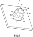
Fig. 5 is a perspective view of the exemplary fastening element represented atfigures 1A, 1B , and2 . - Reference will now be made in detail to the present exemplary embodiments of the disclosure, examples of which are illustrated in the accompanying drawings. Wherever possible, the same reference numbers will be used throughout the drawings to refer to the same or like parts.
-
Figs. 1A and 1B are exemplary side view representations of afastening element 1 installed in asubstrate 3, the substrate is a view in cross section which the cut line passing through the middle of the fastening element and two resilient clips, according embodiments of the present disclosure.Substrates 3 ofFigs. 1A and 1B have different thicknesses S. The thickness S of thesubstrate 3 offigure 1A is greater than the thickness S of thesubstrate 3 offigure 1B . However, the thicknesses illustrated are not intended as to scale nor to be interpreted as the maximum thickness and the minimum thickness of the substrate for which the fastening element according to the invention may be mounted into. Thosefigures 1A and 1B are exemplary only. -
Fastening element 1 may be configured for insertion intosubstrate 3 such thatfastening element 1 has a retention force greater than an insertion force necessary for inserting an anchoringportion 15 of the fastening element into a mounted position onsubstrate 3. When discussing an insertion force, it is intended that such a force be measured by for example, a push/pull gauge (e.g., an IMADA push pull scale) used for applying force to fasteningelement 1 during insertion. When discussing retention force, it is intended that such a force be measured by a similar method, for example, using the pull portion of the push/pull gauge. -
Fastening element 1 may be molded, e.g., injection molded, over-molded, etc. using various materials, for example, thermoplastic, composite, and/or other suitable materials. Thermoplastic materials may include polypropylenes or polyurethanes according to embodiments of the present disclosure. For example, for a polypropylene, a mixture of unsaturated polyester constituted by 50% homopolymer and 50% copolymer can be chosen, having a fluidity index in molten state of 22 g/10 mn and a flexion module of 130,000 to 150,000 psi (896-1034 MPa). Other possible materials include a polypropylene of Atofina, PPC 5660, having a fluidity index in molten state of 7 and a flexion module of 175,000 psi (1206 MPa), propylene copolymers of BP Amoco (Acclear 8949 and Acctuf impact copolymer 3934X) having fluidity index values in molten state of 35 to 100, and flexion modules of 190,000 to 250,000 psi (1310-1723 MPa); polystyrenes, acrylonitrile butadiene styrenes, high density polyethylene, low density linear polyethylene, polycarbonate. The indexes in molten state are between 1 and 100 and the flexion modules are between 30,000 and 1,140,000, preferably between 100,000 and 1,000,000, more preferably between 300,000 and 1,000,000. - Resins other than propylene-based resins which may be suitable include impact polystyrene, acrylonitrile butadiene styrene, nylon, high density polyethylene, low density linear polyethylene, polycarbonate and olefinic thermoplastic resins. Polypropylenes can also be provided which are reinforced by long glass fibers, having a very high flexion module (resin 30YM240/10010 having a flexion module of 856,000 psi (5902 MPa) and resin 40YM240/10010 having a flexion module of 1,140,000 psi (7860 MPa), par sold by StaMax). In this case, the long glass fibers do not migrate into the cavities (which are too small or too thin for the long fibers to penetrate therein), and a very rigid plate is obtained with flexible hooks.
- According to some embodiments,
fastening element 1 is injection molded using a single-step process such that the resulting device is of unitary construction, i.e., all elements offastening element 1 are integrally formed. Such formation may yield desirable strength and ease of fabrication, as well as eliminating subsequent assembly of layered portions (e.g., a gripping portion layer) to a base layer. - The device may comprise a visible injection gate. Alternatively, portions of
fastening element 1 may be injection molded using a single step process, and for example, gripping elements and/or anchoringportion 15 may be joined tofastening element 1 by adhesive, or other suitable bonding (e.g. melting and re-solidification, over-molding, etc.). The base of the gripping portion and the anchoring portion may be integrally molded. When portions offastening element 1 are injection molded using a single step process, since the moulding is carried out in a single step of introduction or injection of the thermoplastic material into the mould, there is no need to wait to mould the hooks, then, to form the hooks, and consequently no interface is formed in the material between the field of hooks and the rest of the moulded article. The moulded article and the hooks are thereby formed uniformly in a single piece. One of the particular features of the product obtained is that the material may penetrate via most or even the entire periphery of the area which is thrust, whilst gathering in a central area according to a pattern which can be a point, a line or a star, according to the form of the field of hooks. Since the material front may not have the time to cool because of the speed of the operation, the joining area may not comprise a true interface (in particular there may be no interface visible to the naked eye) between the hooks and the rest of the moulded article, and consequently this may not result in an area of greater fragility of the part. In some instances, only an analysis of molecular orientation would make it possible to reveal this area. -
Fastening element 1 includes agripping portion 5 having agripping face 6 and aback face 7 opposite thegripping face 6.Fastening element 1 further includes an anchoringportion 15 comprising an anchorproximal end 16 affixed to the gripping portion 5 (e.g., at a geometric center of back face 7) and an anchordistal end 17. - Gripping
portion 5 may be provided with a plurality ofgripping elements 21 and/or 22 extending from gripping portion 5 (e.g., from gripping face 6) at a height H1. For example, agripping face 6 may include a plurality of hooks integrally molded and/or over-molded withfastening element 1. - According to some embodiments,
gripping elements 21 and/or 22 may extend in rows perpendicularly away from grippingportion 5 such that distal portions ofgripping elements 21 and/or 22 are spaced at a predetermined distance from grippingface 6 andback face 7. Importantly, one of skill will understand thatgripping elements 21 and/or 22 may extend in any direction desirable for achieving a desired fastening, and the entire plurality ofgripping elements 21 and/or 22 need not extend in the same direction but the entire plurality of gripping elements may be extended in the same direction. Further, height H1 may vary amonggripping elements 21 and/or 22, or may be substantially uniform. The height H1 of the gripping element comprising hooks may be between 0.1mm and 2mm, in particular between 0.2mm and 1.7 mm or between 0.9mm and 1.43mm. -
Gripping elements 21 and/or 22 may comprise hooks and/or loops whose characteristics enablegripping elements 21 and/or 22 to achieve fastening with another desired surface, for example, a surface comprising a plurality of loops or hooks designed to interact withgripping elements 20 and/or 20' to effect such a fastening.Gripping elements 21 and/or 22 may be arranged in rows and columns. According to someembodiments gripping elements 21 and/or 22 may be arranged with an alternating orientation of their heads within a row, and over substantially the entiregripping face 6, as shown at, for exampleFig. 4 so as to facilitate the fastening with the second surface. Alternatively,gripping elements 21 and/or 22 may be arranged with a single orientation over the entire surface ofgripping face 6. - As used herein the term "head" relating to a
gripping element 21 and/or 22 refers to a distal portion of grippingelement 21 and/or 22 where the active portion of the hook is located (i.e., the curved hooking surface). -
Gripping elements 21 and/or 22 may cover a substantial area associated withgripping face 6. For example, coverage of at least 50, 60, 70, 80 and even 90 percent of gripping surface area may be effected bygripping elements 21 and/or 22. One skilled in the art will recognize that any desirable coverage amount forgripping elements 21 and/or 22 may be implemented without departing from the scope of the present disclosure. The coverage of at least 80, 85, 90, 95 percent of the gripping surface area may be effected bygripping elements 21 and/or 22 in order to maximize the gripping function. - When gripping
elements 21 and/or 22 are implemented as hooks, hooks 21 and/or 22 may have a distinct orientation/bias. In other words, one of skill understands that a single hook has a single direction by which the hooking can be effected. Therefore, it becomes possible to arrange a row ofhooks 21 having a single orientation within the row as shown atFig. 4 . According to some embodiments of the present disclosure, rows having a single orientation may be exclusively placed ongripping face 6, thus providing a plurality of orientations forfastener 1, based on an installation position withsubstrate 3. - Alternatively, according to some embodiments, orientation of
hooks 21 and/or 22 may be alternated throughout a row ofhooks fastener 1 withinsubstrate 3, but with greater flexibility for a material to be fastened (e.g., greater chance of a fastening loop being caught on a hook). - Anchoring
portion 15 may be generally cylindrical in shape and may be provided with a tapered portion at the anchordistal end 17, for example, to facilitate insertion into a through-hole present insubstrate 3, among others. A taper angle of the tapered portion may range from between about 60 degrees to 85 degrees relative to grippingportion 5, particularly around 75 degrees. Importantly, while the term cylindrical is used to describe a shape of anchoringportion 15 in an exemplary embodiment, it is to be understood that a shape of anchoringportion 15 could also be implemented generally as a three-dimensional polygon, e.g., a rectangular cylinder, an elliptical cylinder, etc. In addition, the term "generally" is intended to indicate the shape of anchoring portion absent - According to the embodiment described above, a width W of
resilient clip 20 having the above-described proportions may range, for example, between about 20 and 40 percent of the length H2 of resilient clip, e.g., between about 0.9mm and 2.6mm. One of skill will understand that insertion force may also be tuned depending on the type of material used for fabrication offastening element 1, among others, and that the above described measurements are exemplary only. - In addition, a clearance C between clip
distal end 28 and back face 7 may ranges between about 2 to 5 percent of the length H2 ofresilient clip 20, e.g., between about 0.5 and 2 mm, and in particular, between 1 mm and 2mm. - Each
resilient clip 20 comprises acompression portion 30, ashoulder 35, and a retainingportion 37, among others. -
Compression portion 30 extends from the clipproximal end 29 and be configured to cause a deflection of the at least oneresilient clip 20 toward a radial axis Y of the anchoringportion 15 during insertion of the anchoringportion 15 into a receiver of thesubstrate 3. For example,compression portion 30 may present an acute angle Θ relative to the radial axis Y of anchoringportion 15 ranging between about 20 and 70 degrees, such that, upon insertion into a hole insubstrate 3, compression portion causesresilient clip 20 to be deflected inward toward radial axis Y of anchoringportion 15. According to some embodiments, the angle Θ may correspond to the angle associated with a taper applied to anchoring portiondistal end 17. - As one of skill can understand based on the acute angle Θ, the deflection of
resilient clip 20 becomes greater ascompression portion 30 advances further into the hole, untilshoulder 35 is reached. -
Shoulder portion 35 extends from a terminus of thecompression portion 30 toward the radial axis Y of the anchoringportion 15. For example, the shoulder portion may extend substantially perpendicularly to the radial axis Y of the anchoringportion 15. According to some embodiments,shoulder portion 35 may extend over 5 to 20 percent of the length H2 ofresilient clip 20, for example, between about 0.5 and 2 mm, and in particular between about 1mm and 2 mm. - A shoulder buffer portion may be present and may extend substantially perpendicularly from a terminating portion of the shoulder toward the clip distal end. Shoulder buffer portion may range from about 5 to 20 percent of the overall length of
resilient clip 20, for example, between about 0.4 to 1.5 mm. - Retaining
portion 37 is configured to exert a retaining force on thesubstrate 3 based on the resilient action of the at least oneclip 20. In other words, a biasing force is produced as a result of the resilient nature ofresilient clip 20. This force aids in retaining anchoring portion withinsubstrate 3. In other words, the at least one clip is dimensioned such that a part of the at least one clip extends inside/ into the through-hole of thesubstrate 3, when thefastening element 1 is installed in the through-hole ofsubstrate 3. The part of the clip extending inside the through-hole ofsubstrate 3 exerts a force on the substrate such that the fastener is maintained in position and can resist vibrations without producing sound caused by such vibrations. The retainingportion 37 ofresilient clip 20 extends at a non-orthogonal angle α from a position near the shoulder toward the clip distal end as measured relative to the radial axis Y of the anchoringportion 15. For example, the non-orthogonal angle may range between about 10 degrees and 80 degrees, in particular between 20 degrees and 60 degrees. Thus, when an extraction force is applied, force at the retaining portion increases as an extraction distance increases. This results in a suitably high retaining force. - Based on the presence of retaining
portion 37,shoulder 35 may be prevented from bearing onsubstrate 3 except in cases where an extraction force overcoming the retaining force of retainingportion 37 is applied tofastening element 1. In such a case,shoulder 35 may prevent complete extraction of anchoringportion 15 fromsubstrate 3. - As show at
figures 1A, 1B and2 , the fastener comprises rotational locking means 24. Rotational locking means 24 are configured such that upon turning (rotating) offastening element 1 within a through-hole of the substrate, rotational locking means 24 preventfastening element 1 from turning further than a predetermined point, and may further prevent turningfastening element 1 back to an insertion position. Rotational locking means 24 may also perform a similar function to that ofresilient clips 20, i.e., oncefastening element 1 is turned to a position of locking, rotational locking means 24 may further prevent extraction offastening element 1 fromsubstrate 3. - For example, through-holes in
substrate 3 can have different forms, circular, square, rectangular, triangular, etc . According to some embodiments,fastening element 1 may have rotational locking means 24 to lock the rotation of the fastener when thefastening element 1 is installed in the through-hole of thesubstrate 3. - Rotational locking means 24 comprise a ramp and abutment configuration, wherein the ramp may exert an increasing force on a portion of
substrate 3 asfastening element 1 is rotated, and the abutment may prevent further turning. Based on the increasing force exerted by the ramp, locking means 24 may then also substantially prevent turning offastening element 1 back toward an insertion position. - As show at
figures 2 ,3B and5 , the anchoring portion of the fastening element is hollow of material in the middle such that it defines acavity 50. - On the
figures 1A, 1B ,2, 3A ,3B and5 the plurality of gripping elements are not shown. - According to another embodiment, and as shown at
figures 3A and3B , clipproximal end 29 may be located in proximity to the anchorproximal end 16 and clipdistal end 28 may be located in proximity to the anchordistal end 17. In such a case, a clearance between clipdistal end 28 and a tip of anchoring portion 15 (i.e., at the distal end of anchoring portion 15) may ranges between about 2 to 5 percent of the length ofresilient clip 20, e.g., between about 0.5 and 2 mm, and in particular, between 1mm and 2mm. - Although the present disclosure herein has been described with reference to particular embodiments, it is to be understood that these embodiments are merely illustrative of the principles and applications of the present disclosure.
- Throughout the description, including the claims, the term "comprising a" should be understood as being synonymous with "comprising at least one" unless otherwise stated. In addition, any range set forth in the description, including the claims should be understood as including its end value(s) unless otherwise stated. Specific values for described elements should be understood to be within accepted manufacturing or industry tolerances known to one of skill in the art, and any use of the terms "substantially" and/or "approximately" and/or "generally" should be understood to mean falling within such accepted tolerances, unless otherwise specified herein.
- Where any standards of national, international, or other standards body are referenced (e.g., ISO, etc.), such references are intended to refer to the standard as defined by the national or international standards body as of the priority date of the present specification. Any subsequent substantive changes to such standards are not intended to modify the scope and/or definitions of the present disclosure and/or claims.
- It is intended that the specification and examples be considered as exemplary only, with a true scope of the disclosure being indicated by the following claims.
Claims (16)
- A fastening element (1), comprising:a gripping portion (5) having a gripping face (6) and a back face (7) opposite the gripping face (6), wherein the gripping face (6) comprises at least one of a plurality of hooks and/or a plurality of loops;an anchoring portion (15) comprising an anchor proximal end (16) affixed to the gripping portion (5) and an anchor distal end (17), the anchoring portion (15) comprising at least one resilient clip (20) configured to anchor the fastening element (1) in a substrate (3) with a retention force greater than an insertion force necessary for inserting the anchoring portion (15) into a mounted position on a substrate (3), whereinthe at least one resilient clip (20) comprises:a clip proximal end (29) located in proximity to the anchor distal end (17) and a clip distal end (28) located in proximity to the anchor proximal end (16);a compression portion (30) extending from the clip proximal end (29) and configured to cause a deflection of the at least one clip (20) toward a longitudinal axis of the anchoring portion (15) during insertion of the anchoring portion (15) into a receiver of the substrate (3);a shoulder (35) extending from a terminus of the compression portion (30) toward the longitudinal axis of the anchoring portion (15);a retaining portion (37) configured to exert a retaining force on the substrate (3) based on the resilient action of the at least one clip (20), the retaining portion (37) extending at a non-orthogonal angle from a position near the shoulder (35) toward the clip distal end (28) as measured relative to a radial axis of the anchoring portion (15)wherein the fastening element further comprises rotational locking means (24) configured such that upon turning of the fastening element within a through-hole of the substrate, the rotational locking means prevent the fastening element from turning further than a predetermined point, and further prevent turning the fastening element back to an insertion positionwherein the rotational locking means (24) comprises a ramp and abutment, wherein the ramp is configured to exert an increasing force on a portion of the substrate (3) as the fastening element (1) is rotated, and the abutment is configured to prevent further turning,.
- The fastening element (1) according to claim 1, wherein in an at-rest position of the resilient clip (20), the shoulder (35) extends substantially perpendicularly to the longitudinal axis of the anchoring portion (15).
- The fastening element according to any of claims 1-2, comprising a shoulder buffer portion extending substantially perpendicularly from the shoulder (35) toward the clip distal end (28).
- The fastening element according to any of claims 1-3, wherein the non-orthogonal angle ranges between 10 and 80 degrees as measured relative to a radial axis of the anchoring portion (15).
- The fastening element according any of claims 1-4, wherein the insertion force ranges between about 25 and 45 N and the retention force is higher than 133N, in particular the retention force is in range between about 133N and 250 N.
- The fastening element according to claim 1, wherein the gripping face (6) comprises a plurality of hooks integrally molded with the fastening element (1).
- The fastening element according to any of claims 1-6, wherein a length of the at least one resilient clip (20) ranges between 3.5 and 5.5 mm as measured from a tip of the clip distal end (28) to a base of the clip proximal end (29), in particular between 4.5mm and 5.5mm.
- The fastening element according to any of claims 1-7, wherein the anchoring portion (15) is integrally molded with the gripping portion (5).
- The fastening element according to any of claims 1-8, wherein the anchoring portion (15) is fastened to the back face (7) by at least one of gluing and overmolding.
- The fastening element (1) according to any of claims 1-9, wherein a clearance between the clip distal end (28) and the back face (7) ranges between 0.5 and 2 mm, in particular between 1mm and 2mm, and wherein a width of the at least one clip (20) ranges between 0.9 and 2.6 mm.
- The fastening element (1) according to any of claims 1-10, wherein the fastening element (1) and anchoring portion (15) are molded of a thermoplastic material.
- The fastening element (1) according to any of claims 1-11, wherein the shoulder (35) has a width similar to the width of the one clip, in particular a width ranging from 0.4 to 1.5mm.
- An multi-substrate anchor (15) for a fastening element, comprising:an anchor proximal end (16) and an anchor distal end (17), the anchor comprising at least one resilient clip (20) configured to anchor the fastening element in any one of a plurality of substrates (3), each of the substrates (3) having a thickness that is different from the other substrates (3), whereinthe at least one resilient clip (20) comprises:a clip proximal end (29) located in proximity to the anchor distal end and a clip distal end (28) located in proximity to the anchor proximal end (16);a compression portion (30) extending from the clip proximal end (29) and configured to cause a deflection of the at least one clip (20) toward a longitudinal axis of the multi-substrate anchor (15) during insertion of the multi-substrate anchor (15) into a through-hole in the substrate (3);a shoulder (35) extending from a terminus of the compression portion (30) toward the longitudinal axis of the anchor (15);a substrate interface extending from a point near the shoulder (35) and configured to exert a retaining force on at least a portion of the thickness within the through-hole in the substrate (3) based on the resilient action of the at least one clip (20), the substrate interface extending toward the clip distal end (28) at an acute angle relative to the longitudinal axis of the multi-substrate anchor (15), wherein in an at-rest position of the resilient clip (20), the shoulder (35) extends perpendicularly to the longitudinal axis of the multi-substrate anchor (15),wherein the multi-substrate anchor (15) further comprises rotational locking means (24) configured such that upon turning of the fastening element within a through-hole of the substrate, the rotational locking means prevent the fastening element from turning further than a predetermined point, and further prevent turning the fastening element back to an insertion position,wherein the rotational locking means (24) comprises a ramp and abutment, wherein the ramp is configured to exert an increasing force on a portion of the substrate (3) as the fastening element (1) is rotated, and the abutment is configured to prevent further turning.
- The multi-substrate anchor (15) according to claim 13, comprising a shoulder buffer portion extending perpendicularly from the shoulder (35) toward the clip distal end (28).
- The multi-substrate anchor (15) according to any of claims 13-14, wherein the clip (20) is configured such that the shoulder (35) does not bear on the substrate (3) when the anchor (25) is in an installed position unless an extraction force is applied to the anchor (15).
- A fastening element, comprising:a gripping portion having a gripping face and a back face opposite the gripping face;an anchoring portion comprising an anchor proximal end affixed to the gripping portion and an anchor distal end, the anchoring portion comprising at least one resilient clip configured to anchor the fastening element in a substrate with a retention force greater than an insertion force necessary for inserting the anchoring portion into a mounted position on a substrate, whereinthe at least one resilient clip comprises:a clip proximal end located in proximity to the anchor proximal end and a clip distal end;a compression portion extending at an angle from the clip distal end and configured to cause a deflection of the at least one clip toward a longitudinal axis of the anchoring portion during insertion of the anchoring portion into a receiver of the substrate;a shoulder extending from a terminus of the compression portion toward the longitudinal axis of the anchoring portion;a retaining portion configured to exert a retaining force on the substrate based on the resilient action of the at least one clip, the retaining portion extending at a non-orthogonal angle from a position near the shoulder toward the clip proximal end as measured relative to a radial axis of the anchoring portion.wherein the fastening element further comprises rotational locking means (24) configured such that upon turning of the fastening element within a through-hole of the substrate, the rotational locking means prevent the fastening element from turning further than a predetermined point, and further prevent turning the fastening element back to an insertion position,wherein the rotational locking means (24) comprises a ramp and abutment, wherein the ramp is configured to exert an increasing force on a portion of the substrate (3) as the fastening element (1) is rotated, and the abutment is configured to prevent further turning.
Applications Claiming Priority (2)
| Application Number | Priority Date | Filing Date | Title |
|---|---|---|---|
| US15/246,563 US10202085B2 (en) | 2016-08-25 | 2016-08-25 | Fastener |
| PCT/EP2017/071302 WO2018037068A1 (en) | 2016-08-25 | 2017-08-24 | Fastener |
Publications (3)
| Publication Number | Publication Date |
|---|---|
| EP3504446A1 EP3504446A1 (en) | 2019-07-03 |
| EP3504446B1 true EP3504446B1 (en) | 2024-08-21 |
| EP3504446C0 EP3504446C0 (en) | 2024-08-21 |
Family
ID=59791050
Family Applications (1)
| Application Number | Title | Priority Date | Filing Date |
|---|---|---|---|
| EP17761838.6A Active EP3504446B1 (en) | 2016-08-25 | 2017-08-24 | Fastener |
Country Status (7)
| Country | Link |
|---|---|
| US (1) | US10202085B2 (en) |
| EP (1) | EP3504446B1 (en) |
| JP (1) | JP7051817B2 (en) |
| KR (1) | KR102597419B1 (en) |
| CN (1) | CN109642598B (en) |
| BR (1) | BR112019002522B1 (en) |
| WO (1) | WO2018037068A1 (en) |
Families Citing this family (6)
| Publication number | Priority date | Publication date | Assignee | Title |
|---|---|---|---|---|
| US10197089B2 (en) * | 2016-09-01 | 2019-02-05 | Nifco America Corp. | Clip and clip attaching structure |
| JP6530002B2 (en) * | 2017-04-12 | 2019-06-12 | 日本電信電話株式会社 | CONTENT SEARCH DEVICE, CONTENT SEARCH METHOD, PROGRAM |
| KR102816361B1 (en) * | 2018-06-27 | 2025-06-02 | 일리노이즈 툴 워크스 인코포레이티드 | Fasteners |
| FR3112928B1 (en) * | 2020-08-03 | 2022-10-21 | Aplix Sa | Restraint device, absorbent article comprising such a device, and method of making such a device |
| DE102020121313A1 (en) * | 2020-08-13 | 2022-02-17 | Webasto SE | Roof arrangement with sky element |
| KR102496813B1 (en) * | 2020-08-31 | 2023-02-06 | 현대자동차 주식회사 | Push nut for vehicle |
Family Cites Families (22)
| Publication number | Priority date | Publication date | Assignee | Title |
|---|---|---|---|---|
| US2836215A (en) * | 1954-08-11 | 1958-05-27 | Illinois Tool Works | Plastic nut-like fastener with resilient wings |
| US3851357A (en) * | 1971-02-03 | 1974-12-03 | American Velcro Inc | Fastener |
| USD269589S (en) * | 1980-05-31 | 1983-07-05 | Nifco, Inc. | Combined fixing and retaining clip for elongate bodies |
| US5058245A (en) | 1989-10-31 | 1991-10-22 | Kuraray Co., Ltd. | Fastening device and method for fixing adherend by using the same |
| US5012995A (en) * | 1990-03-16 | 1991-05-07 | General Motors Corporation | Adjustable wiring harness clip |
| JPH0741364Y2 (en) * | 1990-07-03 | 1995-09-27 | ワイケイケイ株式会社 | Fasteners for fixing plates |
| US5242646A (en) * | 1992-05-07 | 1993-09-07 | Minnesota Mining And Manufacturing Company | Method of making an interengaging fastener member |
| USD360574S (en) * | 1993-04-19 | 1995-07-25 | Yoshida Kogyo K.K. | Surface fastener with elastic double hook for fastening platelike article |
| JPH08270624A (en) * | 1995-03-29 | 1996-10-15 | Piolax Inc | Clip |
| USD392877S (en) * | 1995-10-12 | 1998-03-31 | Nifco Inc. | Face attachment |
| US7018496B1 (en) | 1999-04-26 | 2006-03-28 | 3M Innovative Properties Company | Curable mechanical fasteners |
| JP2003322130A (en) * | 2002-05-08 | 2003-11-14 | Aoyama Seisakusho Co Ltd | Fastening parts |
| US7594629B2 (en) * | 2006-06-09 | 2009-09-29 | Delphi Technologies, Inc. | Clip for fastening an article to a panel |
| US20080066266A1 (en) * | 2006-09-14 | 2008-03-20 | Derek Scroggie | Fastener assembly |
| US7337505B1 (en) | 2007-03-13 | 2008-03-04 | Illinois Tool Works Inc | Panel fastener |
| US20090126168A1 (en) * | 2007-11-15 | 2009-05-21 | Kobe James J | Multi-Angle Pop-In Mechanical Fastener |
| FR2938025B1 (en) * | 2008-11-04 | 2013-05-24 | Trw Automotive Electron & Comp | CLAMP FOR ATTACHING EQUIPMENT TO A STRUCTURE |
| DE102012001457A1 (en) * | 2012-01-25 | 2013-07-25 | Volkswagen Aktiengesellschaft | fastening system |
| FR2991407B1 (en) * | 2012-06-01 | 2014-07-25 | Illinois Tool Works | ATTACHMENT HAVING A CLAMPING FOOT TO BE PRESSED THROUGH A HOLE OF A PANEL AND A COMMITMENT HEAD CONFIGURED TO BE IN PLACE OF SAID PANEL |
| DE102012010893A1 (en) | 2012-06-01 | 2013-12-05 | Gottlieb Binder Gmbh & Co. Kg | fastening system |
| JP6310644B2 (en) | 2013-05-16 | 2018-04-11 | スリーエム イノベイティブ プロパティズ カンパニー | Fastener member, fastener structure, and support |
| JP6328476B2 (en) | 2014-04-16 | 2018-05-23 | 大和化成工業株式会社 | clip |
-
2016
- 2016-08-25 US US15/246,563 patent/US10202085B2/en active Active
-
2017
- 2017-08-24 KR KR1020197007726A patent/KR102597419B1/en active Active
- 2017-08-24 CN CN201780052311.4A patent/CN109642598B/en active Active
- 2017-08-24 BR BR112019002522-7A patent/BR112019002522B1/en active IP Right Grant
- 2017-08-24 EP EP17761838.6A patent/EP3504446B1/en active Active
- 2017-08-24 JP JP2019510796A patent/JP7051817B2/en active Active
- 2017-08-24 WO PCT/EP2017/071302 patent/WO2018037068A1/en not_active Ceased
Also Published As
| Publication number | Publication date |
|---|---|
| WO2018037068A1 (en) | 2018-03-01 |
| US20180056893A1 (en) | 2018-03-01 |
| BR112019002522A2 (en) | 2019-05-28 |
| KR102597419B1 (en) | 2023-11-03 |
| BR112019002522B1 (en) | 2022-12-13 |
| CN109642598B (en) | 2021-08-20 |
| JP2019532230A (en) | 2019-11-07 |
| US10202085B2 (en) | 2019-02-12 |
| JP7051817B2 (en) | 2022-04-11 |
| CN109642598A (en) | 2019-04-16 |
| EP3504446A1 (en) | 2019-07-03 |
| KR20190042034A (en) | 2019-04-23 |
| EP3504446C0 (en) | 2024-08-21 |
Similar Documents
| Publication | Publication Date | Title |
|---|---|---|
| EP3504446A1 (en) | Fastener | |
| US6613415B2 (en) | Emblem having a fastening structure | |
| US9820537B2 (en) | Fastener | |
| US20040137192A1 (en) | Injection molded fastening article for use as a mold insert | |
| EP2222967A2 (en) | Multi-angle pop-in mechanical fastener | |
| US20150135484A1 (en) | Fastener comprising a snap-engagement foot to push through a hole in a panel and an engagement head configured to jut over said panel | |
| CN105283295A (en) | Method for producing a connecting part, connecting part produced in accordance with the method, tool for producing such a connecting part and fastening system having such a connecting part | |
| KR100546426B1 (en) | Hanging member for mold-in molding and manufacturing method of resin molded body having same | |
| US20160214547A1 (en) | Magnet fastener assembly | |
| CN101331029B (en) | EA material, its fixing clip and fixing structure | |
| US11007952B2 (en) | Magnet fastener assembly and base therefor with relatively rigid upstanding doghouse on a relatively flexible support | |
| KR20050062417A (en) | Wheel cover for automotive vehicles | |
| EP3973811A1 (en) | Hook-and-loop fastener-equipped resin molded body, method for manufacturing same, and method for fixing automobile ceiling material to vehicle body | |
| KR20150097460A (en) | Device and method for providing structural reinforcement and/or sound and vibration control within the cavities of hollow members of a vehicle body | |
| US20090096251A1 (en) | Securing mechanism | |
| EP2374643B1 (en) | Vehicle interior component | |
| US10188179B2 (en) | Fastener | |
| JPH10318221A (en) | Engaging member having coupling element to support body and additionally attaching member having the engaging member | |
| US10695962B2 (en) | Members for directing expandable material for baffling, sealing, reinforcing | |
| KR200181168Y1 (en) | Interengaging fastener member with integral affixation means | |
| JP5605070B2 (en) | Foam molded member, clip for mounting the foam, method for manufacturing foam molded member, and mounting structure for foam molded member |
Legal Events
| Date | Code | Title | Description |
|---|---|---|---|
| STAA | Information on the status of an ep patent application or granted ep patent |
Free format text: STATUS: UNKNOWN |
|
| STAA | Information on the status of an ep patent application or granted ep patent |
Free format text: STATUS: THE INTERNATIONAL PUBLICATION HAS BEEN MADE |
|
| PUAI | Public reference made under article 153(3) epc to a published international application that has entered the european phase |
Free format text: ORIGINAL CODE: 0009012 |
|
| STAA | Information on the status of an ep patent application or granted ep patent |
Free format text: STATUS: REQUEST FOR EXAMINATION WAS MADE |
|
| 17P | Request for examination filed |
Effective date: 20190325 |
|
| AK | Designated contracting states |
Kind code of ref document: A1 Designated state(s): AL AT BE BG CH CY CZ DE DK EE ES FI FR GB GR HR HU IE IS IT LI LT LU LV MC MK MT NL NO PL PT RO RS SE SI SK SM TR |
|
| AX | Request for extension of the european patent |
Extension state: BA ME |
|
| DAV | Request for validation of the european patent (deleted) | ||
| DAX | Request for extension of the european patent (deleted) | ||
| STAA | Information on the status of an ep patent application or granted ep patent |
Free format text: STATUS: EXAMINATION IS IN PROGRESS |
|
| 17Q | First examination report despatched |
Effective date: 20210120 |
|
| P01 | Opt-out of the competence of the unified patent court (upc) registered |
Effective date: 20230513 |
|
| GRAP | Despatch of communication of intention to grant a patent |
Free format text: ORIGINAL CODE: EPIDOSNIGR1 |
|
| STAA | Information on the status of an ep patent application or granted ep patent |
Free format text: STATUS: GRANT OF PATENT IS INTENDED |
|
| INTG | Intention to grant announced |
Effective date: 20240216 |
|
| TPAC | Observations filed by third parties |
Free format text: ORIGINAL CODE: EPIDOSNTIPA |
|
| GRAS | Grant fee paid |
Free format text: ORIGINAL CODE: EPIDOSNIGR3 |
|
| GRAA | (expected) grant |
Free format text: ORIGINAL CODE: 0009210 |
|
| STAA | Information on the status of an ep patent application or granted ep patent |
Free format text: STATUS: THE PATENT HAS BEEN GRANTED |
|
| AK | Designated contracting states |
Kind code of ref document: B1 Designated state(s): AL AT BE BG CH CY CZ DE DK EE ES FI FR GB GR HR HU IE IS IT LI LT LU LV MC MK MT NL NO PL PT RO RS SE SI SK SM TR |
|
| REG | Reference to a national code |
Ref country code: GB Ref legal event code: FG4D |
|
| REG | Reference to a national code |
Ref country code: CH Ref legal event code: EP |
|
| REG | Reference to a national code |
Ref country code: IE Ref legal event code: FG4D |
|
| REG | Reference to a national code |
Ref country code: DE Ref legal event code: R096 Ref document number: 602017084265 Country of ref document: DE |
|
| U01 | Request for unitary effect filed |
Effective date: 20240821 |
|
| U07 | Unitary effect registered |
Designated state(s): AT BE BG DE DK EE FI FR IT LT LU LV MT NL PT SE SI Effective date: 20240827 |
|
| P04 | Withdrawal of opt-out of the competence of the unified patent court (upc) registered |
Free format text: CASE NUMBER: APP_48406/2024 Effective date: 20240822 |
|
| U20 | Renewal fee for the european patent with unitary effect paid |
Year of fee payment: 8 Effective date: 20240923 |
|
| P05 | Withdrawal of opt-out of the competence of the unified patent court (upc) changed |
Free format text: CASE NUMBER: APP_48406/2024 Effective date: 20240827 |
|
| PG25 | Lapsed in a contracting state [announced via postgrant information from national office to epo] |
Ref country code: NO Free format text: LAPSE BECAUSE OF FAILURE TO SUBMIT A TRANSLATION OF THE DESCRIPTION OR TO PAY THE FEE WITHIN THE PRESCRIBED TIME-LIMIT Effective date: 20241121 |
|
| PG25 | Lapsed in a contracting state [announced via postgrant information from national office to epo] |
Ref country code: GR Free format text: LAPSE BECAUSE OF FAILURE TO SUBMIT A TRANSLATION OF THE DESCRIPTION OR TO PAY THE FEE WITHIN THE PRESCRIBED TIME-LIMIT Effective date: 20241122 Ref country code: PL Free format text: LAPSE BECAUSE OF FAILURE TO SUBMIT A TRANSLATION OF THE DESCRIPTION OR TO PAY THE FEE WITHIN THE PRESCRIBED TIME-LIMIT Effective date: 20240821 |
|
| PG25 | Lapsed in a contracting state [announced via postgrant information from national office to epo] |
Ref country code: IS Free format text: LAPSE BECAUSE OF FAILURE TO SUBMIT A TRANSLATION OF THE DESCRIPTION OR TO PAY THE FEE WITHIN THE PRESCRIBED TIME-LIMIT Effective date: 20241221 |
|
| PG25 | Lapsed in a contracting state [announced via postgrant information from national office to epo] |
Ref country code: HR Free format text: LAPSE BECAUSE OF FAILURE TO SUBMIT A TRANSLATION OF THE DESCRIPTION OR TO PAY THE FEE WITHIN THE PRESCRIBED TIME-LIMIT Effective date: 20240821 |
|
| PG25 | Lapsed in a contracting state [announced via postgrant information from national office to epo] |
Ref country code: RS Free format text: LAPSE BECAUSE OF FAILURE TO SUBMIT A TRANSLATION OF THE DESCRIPTION OR TO PAY THE FEE WITHIN THE PRESCRIBED TIME-LIMIT Effective date: 20241121 Ref country code: ES Free format text: LAPSE BECAUSE OF FAILURE TO SUBMIT A TRANSLATION OF THE DESCRIPTION OR TO PAY THE FEE WITHIN THE PRESCRIBED TIME-LIMIT Effective date: 20240821 |
|
| PG25 | Lapsed in a contracting state [announced via postgrant information from national office to epo] |
Ref country code: RS Free format text: LAPSE BECAUSE OF FAILURE TO SUBMIT A TRANSLATION OF THE DESCRIPTION OR TO PAY THE FEE WITHIN THE PRESCRIBED TIME-LIMIT Effective date: 20241121 Ref country code: PL Free format text: LAPSE BECAUSE OF FAILURE TO SUBMIT A TRANSLATION OF THE DESCRIPTION OR TO PAY THE FEE WITHIN THE PRESCRIBED TIME-LIMIT Effective date: 20240821 Ref country code: NO Free format text: LAPSE BECAUSE OF FAILURE TO SUBMIT A TRANSLATION OF THE DESCRIPTION OR TO PAY THE FEE WITHIN THE PRESCRIBED TIME-LIMIT Effective date: 20241121 Ref country code: IS Free format text: LAPSE BECAUSE OF FAILURE TO SUBMIT A TRANSLATION OF THE DESCRIPTION OR TO PAY THE FEE WITHIN THE PRESCRIBED TIME-LIMIT Effective date: 20241221 Ref country code: HR Free format text: LAPSE BECAUSE OF FAILURE TO SUBMIT A TRANSLATION OF THE DESCRIPTION OR TO PAY THE FEE WITHIN THE PRESCRIBED TIME-LIMIT Effective date: 20240821 Ref country code: GR Free format text: LAPSE BECAUSE OF FAILURE TO SUBMIT A TRANSLATION OF THE DESCRIPTION OR TO PAY THE FEE WITHIN THE PRESCRIBED TIME-LIMIT Effective date: 20241122 Ref country code: ES Free format text: LAPSE BECAUSE OF FAILURE TO SUBMIT A TRANSLATION OF THE DESCRIPTION OR TO PAY THE FEE WITHIN THE PRESCRIBED TIME-LIMIT Effective date: 20240821 |
|
| REG | Reference to a national code |
Ref country code: CH Ref legal event code: PL |
|
| PG25 | Lapsed in a contracting state [announced via postgrant information from national office to epo] |
Ref country code: SM Free format text: LAPSE BECAUSE OF FAILURE TO SUBMIT A TRANSLATION OF THE DESCRIPTION OR TO PAY THE FEE WITHIN THE PRESCRIBED TIME-LIMIT Effective date: 20240821 |
|
| PG25 | Lapsed in a contracting state [announced via postgrant information from national office to epo] |
Ref country code: CH Free format text: LAPSE BECAUSE OF NON-PAYMENT OF DUE FEES Effective date: 20240831 |
|
| PG25 | Lapsed in a contracting state [announced via postgrant information from national office to epo] |
Ref country code: CZ Free format text: LAPSE BECAUSE OF FAILURE TO SUBMIT A TRANSLATION OF THE DESCRIPTION OR TO PAY THE FEE WITHIN THE PRESCRIBED TIME-LIMIT Effective date: 20240821 |
|
| PG25 | Lapsed in a contracting state [announced via postgrant information from national office to epo] |
Ref country code: SK Free format text: LAPSE BECAUSE OF FAILURE TO SUBMIT A TRANSLATION OF THE DESCRIPTION OR TO PAY THE FEE WITHIN THE PRESCRIBED TIME-LIMIT Effective date: 20240821 |
|
| PLBE | No opposition filed within time limit |
Free format text: ORIGINAL CODE: 0009261 |
|
| STAA | Information on the status of an ep patent application or granted ep patent |
Free format text: STATUS: NO OPPOSITION FILED WITHIN TIME LIMIT |
|
| PG25 | Lapsed in a contracting state [announced via postgrant information from national office to epo] |
Ref country code: MC Free format text: LAPSE BECAUSE OF FAILURE TO SUBMIT A TRANSLATION OF THE DESCRIPTION OR TO PAY THE FEE WITHIN THE PRESCRIBED TIME-LIMIT Effective date: 20240821 |
|
| GBPC | Gb: european patent ceased through non-payment of renewal fee |
Effective date: 20241121 |
|
| PG25 | Lapsed in a contracting state [announced via postgrant information from national office to epo] |
Ref country code: IE Free format text: LAPSE BECAUSE OF NON-PAYMENT OF DUE FEES Effective date: 20240824 |
|
| 26N | No opposition filed |
Effective date: 20250522 |
|
| U20 | Renewal fee for the european patent with unitary effect paid |
Year of fee payment: 9 Effective date: 20250820 |
|
| PG25 | Lapsed in a contracting state [announced via postgrant information from national office to epo] |
Ref country code: GB Free format text: LAPSE BECAUSE OF NON-PAYMENT OF DUE FEES Effective date: 20241121 |
|
| PG25 | Lapsed in a contracting state [announced via postgrant information from national office to epo] |
Ref country code: RO Free format text: LAPSE BECAUSE OF FAILURE TO SUBMIT A TRANSLATION OF THE DESCRIPTION OR TO PAY THE FEE WITHIN THE PRESCRIBED TIME-LIMIT Effective date: 20240821 |
|
| PG25 | Lapsed in a contracting state [announced via postgrant information from national office to epo] |
Ref country code: CY Free format text: LAPSE BECAUSE OF FAILURE TO SUBMIT A TRANSLATION OF THE DESCRIPTION OR TO PAY THE FEE WITHIN THE PRESCRIBED TIME-LIMIT; INVALID AB INITIO Effective date: 20170824 |
|
| PG25 | Lapsed in a contracting state [announced via postgrant information from national office to epo] |
Ref country code: HU Free format text: LAPSE BECAUSE OF FAILURE TO SUBMIT A TRANSLATION OF THE DESCRIPTION OR TO PAY THE FEE WITHIN THE PRESCRIBED TIME-LIMIT; INVALID AB INITIO Effective date: 20170824 |