EP3504087B1 - Inflatable device - Google Patents
Inflatable device Download PDFInfo
- Publication number
- EP3504087B1 EP3504087B1 EP17761556.4A EP17761556A EP3504087B1 EP 3504087 B1 EP3504087 B1 EP 3504087B1 EP 17761556 A EP17761556 A EP 17761556A EP 3504087 B1 EP3504087 B1 EP 3504087B1
- Authority
- EP
- European Patent Office
- Prior art keywords
- bladder
- sleeve member
- inflatable bladder
- inflation
- inflatable
- Prior art date
- Legal status (The legal status is an assumption and is not a legal conclusion. Google has not performed a legal analysis and makes no representation as to the accuracy of the status listed.)
- Not-in-force
Links
Images




Classifications
-
- B—PERFORMING OPERATIONS; TRANSPORTING
- B60—VEHICLES IN GENERAL
- B60N—SEATS SPECIALLY ADAPTED FOR VEHICLES; VEHICLE PASSENGER ACCOMMODATION NOT OTHERWISE PROVIDED FOR
- B60N2/00—Seats specially adapted for vehicles; Arrangement or mounting of seats in vehicles
- B60N2/58—Seat coverings
- B60N2/60—Removable protective coverings
- B60N2/6009—Removable protective coverings covering more than only the seat
-
- B—PERFORMING OPERATIONS; TRANSPORTING
- B60—VEHICLES IN GENERAL
- B60R—VEHICLES, VEHICLE FITTINGS, OR VEHICLE PARTS, NOT OTHERWISE PROVIDED FOR
- B60R7/00—Stowing or holding appliances inside vehicle primarily intended for personal property smaller than suit-cases, e.g. travelling articles, or maps
- B60R7/04—Stowing or holding appliances inside vehicle primarily intended for personal property smaller than suit-cases, e.g. travelling articles, or maps in driver or passenger space, e.g. using racks
- B60R7/043—Stowing or holding appliances inside vehicle primarily intended for personal property smaller than suit-cases, e.g. travelling articles, or maps in driver or passenger space, e.g. using racks mounted on or under a seat
Definitions
- the invention to which this application relates is an apparatus which provides a blockage and/or storage for preventing loss of small objects from a front vehicle seat.
- the following description refers exclusively to the provision of an apparatus for use with the seat of a car, the skilled person will appreciate that the present invention could also be used in other vehicles or non-vehicles wherein a gap between two objects is required to be blocked.
- foam portions which are provided to be inserted between the side of the seat and the centre console.
- foam portions are generally provided in one size, or a non-adjustable size, and will more often than not be either too big or too small for the gap they are intended to fill, depending on the make and model of the vehicle in which they are to be located.
- these foam portions can be unsightly and can be easily stained or damaged if, for example, a user spills a drink or food thereon. This can absorb into the material, creating a permanent stain or smell.
- an apparatus arranged to be inserted between two objects, in use, said apparatus including an inflatable bladder; and characterized in that inflation means are provided associated with the bladder to permit selectable inflation and deflation of the apparatus by a user.
- said objects may be the seat of a vehicle and a central console of the vehicle.
- the apparatus may be placed between the side of the seat and the central console and inflated so as to fill or plug the gab there previously.
- the dropped item merely rests on the apparatus of the present invention and can be immediately picked back up by the user.
- the inflatable bladder forms an elongate member.
- said bladder is laterally inflatable, with respect to a longitudinal axis thereof.
- said inflatable bladder is formed from an expandable and/or elastic material.
- said bladder is inflatable to a size as required by a user to fit a particular gap.
- the same apparatus as provided by the present invention will be suitable to fill gaps of varying sizes in, for example, different vehicles and the like.
- the present invention effectively provides a "one size fits all" inflatable apparatus.
- a valve member may be provided associated with the inflation means to permit deflation of the bladder.
- said inflation means are provided as manual inflation means.
- Said inflation means comprise a bulb pump member.
- said bulb pump member includes a bulb body, air inlet means, and air outlet means.
- said air inlet means comprise a one-way valve and said air outlet means comprise a one-way valve.
- said bulb body may be provided as a compressible body, formed from a resilient material.
- said inflation means includes conduit means, provided intermediate said bulb pump member and said inflatable bladder.
- said inflation means is arranged to expel air from a bulb body, through air outlet means and into said inflatable bladder, via said conduit means.
- said conduit means further includes a valve member therewith.
- said valve member is actuable to permit release of air from, and thus deflation of, the inflatable bladder.
- said inflation means may be provided at or adjacent a first end of the bladder.
- said inflation means may be provided to extend from a longitudinal edge at or adjacent a first end of the bladder.
- the apparatus further includes a sleeve member.
- Z Said inflatable bladder is provided to be located within, or at least partially within, said sleeve member.
- said sleeve member comprises an elongate member.
- said sleeve member includes at least one aperture, through which said inflatable bladder may be inserted.
- said at least one aperture is located at or adjacent a first end of the sleeve member.
- said bladder is arranged to be inserted into said sleeve member when in a deflated configuration.
- said sleeve member includes at least two apertures, located at or adjacent first and second opposing ends of the sleeve member.
- said at least one aperture is provided as a first slot, located along part of a longitudinal edge of the sleeve member, at or adjacent a first end thereof.
- a second aperture is provided as a second slot, located along part of the same longitudinal edge of the sleeve member as the first slot, at or adjacent a second, opposing end thereof.
- the provision of at least two slots enables a user to insert or feed the inflatable bladder through a first slot, and either as it is expanding/inflating or prior thereto, can use the second slot to insert their own fingers or hand etc. and grip the leading end of the bladder, pulling it along the length of the sleeve member to ensure it expands and fills the sleeve member correctly as it is inflated.
- said sleeve member is provided of a size and dimensions to accommodate said inflatable bladder when in an inflated configuration.
- said sleeve member may be expandable upon inflation of the inflatable bladder.
- said sleeve member may be formed from an expandable and/or elastic material.
- said sleeve member may be provided with an exterior colour, texture and/or material to match that of the upholstery of the vehicle in which the apparatus is to be located.
- said sleeve member may include an opening located along a longitudinal axis, or part thereof.
- said opening may be provided with fastening means to close the same.
- said fastening means may comprise any of the following: a zip fastener, hook and loop fasteners, studs, clips and/or the like.
- said sleeve member may include one or more logos, branding messages and/or the like provided thereon.
- said logo and/or branding may be provided to be that of a manufacture of the vehicle in which the apparatus is to be located, the brand of a leasing or vehicle rental company, apparatus manufacturer, and/or the like.
- said sleeve member may include custom design, messages, names or logos, as determined by a user.
- the provision of the at least two apertures or slots enables a user to place both the sleeve member and the inflatable bladder in a preferred orientation, allowing the imagery, branding, messages names and/or logos to be optimally displayed.
- said sleeve member may be interchangeable with the inflatable bladder.
- different sleeve members may be provided for different vehicles, without the need to provide additional bladders.
- a method of manufacturing an apparatus arranged to be inserted between two objects including the steps of: forming and proving an inflatable bladder; and characterized in that inflation means are provided associated with the bladder to permit selectable inflation and deflation of the apparatus by a user.
- a method of using an apparatus arranged to be inserted between two objects including the steps of: providing an apparatus as described above; locating the inflatable bladder in a gap between the two objects, as required; and actuating the inflation means to inflate the bladder to fill the gap.
- a sleeve member is provided.
- Said inflatable bladder, prior to inflation is located within, or at least partially within, said sleeve member, and subsequently located in the gap between the two objects.
- a valve member is provided associated with the inflation means to permit deflation of the bladder.
- the valve member may be actuated to permit deflation and subsequent removal of the apparatus from the gap.
- an apparatus A for inserting, in use, into a space or gap between two objects for example, a vehicular seat and another object or structure, in particular such as the transmission tunnel, central console or coin tidy.
- a space or gap may be filled and small objects prevented from falling into this space.
- the apparatus A thereby comprises an elongate body formed from an inflatable bladder 10, and further comprises an outer sleeve 6 located over the inner bladder 10, the body arranged to fit into the space or gap.
- the apparatus A may be available in a plurality of sizes according to make and model.
- the body is adjustable in diameter so as to expand or contract to fit the space or gap.
- Embodiments of the apparatus A comprise inflation means so as to minimise size for non-use, transport or storage.
- the apparatus A may therefore comprise a laterally expandable body which is elongate in shape, so as to effectively fill the narrow space or gap defined between a seat and the central feature of a standard vehicle such as a car.
- inflation means are provided in the form of an inflation mechanism 1, comprising a manual rubber or elastomer pump bulb 3 situated on a conduit in the form of a flexible tube 5, which may be screwed into a collar 9 on the bladder, and depending from the bottom face of the body, adjacent an end.
- the collar 9 may be formed from any or any combination of a plastics, PVC, metal or metal alloy material.
- This inflation mechanism 1 comprises a release valve mechanism 4 bonded directly into the inflation tube 5 which is turned to release the air and an air inlet 14.
- the inflation mechanism comprises a manual bulb 33 with grip pads 35, and a tube 34 connection to the bladder 37, as well as an inflation valve 11.
- the inflation mechanism may comprise a self-inflation valve, wherein the bladder is biased to open.
- the enlargement mechanism may be combined with or complementary to a length adjustment means.
- the apparatus A therefore comprises an elongate body sized to fit between a front seat and centre console of a vehicle and in some embodiments adjustable in size.
- the first pictured embodiment provides an inflatable bladder 10 which can be placed down the side of the seat or seats to prevent objects from passing and falling down. Finishes and covers 6 may help the apparatus A blend in with the vehicle's interior styling.
- the apparatus A may comprise a displaceable cover system suitable for customising the aesthetics of the apparatus A, for example as shown in the second embodiment.
- the bladder In its deflated state, the bladder can be stored flat or may be rolled up.
- the body as pictured comprises a top and bottom face, and sides connecting the top and bottom, and two ends 7,8, wherein end 8 is envisaged to be towards the rear of the seat in use.
- the top and bottom may be identical in some embodiments. In other embodiments, the top may provide a substantially flat top, so as to enable a user to use the top as a useful surface.
- the bladder and cover are formed of a plurality of pieces, wherein the cover comprises an external ridge or seam 15 and plural end sections 16.
- the seam may combine with a lozenge shape in section to the body in limiting rotation, wherein the seam catches on the surrounding objects or surfaces.
- the seam may be formed in a separate or resiliently deformable material or format, for example comprising a silicone braiding.
- the cover 6 may be provided in the form of a sleeve member, in which the bladder may be at least partially located.
- the cover 6 is elongate and includes at least a first aperture or slot 71 through which the bladder 10 may be inserted.
- the bladder 10 is arranged to be inserted into the cover 6 when in a deflated configuration.
- the slot 71 may be located along part of a longitudinal edge 73 of the cover 6, at or adjacent a first end thereof.
- two slots 71, 75 may be provided on the cover 6, each located along part of the same longitudinal edge of the sleeve/cover, at or adjacent opposing ends thereof.
- the provision of at least two slots, 71, 75 enables a user to insert or feed the inflatable bladder 10 through a first slot 71, and either as it is expanding/inflating or prior thereto, can use the second slot 75 to insert their own fingers or hand etc. and grip the leading end of the bladder 10, pulling it along the length of the cover 6 to ensure it expands and fills the cover 6 correctly as it is inflated.
- the top may be provided with a surface arranged for use, for example comprising indentations, hook and loop material such as Velcro (RTM) or substantially rigid material or coating.
- a surface arranged for use for example comprising indentations, hook and loop material such as Velcro (RTM) or substantially rigid material or coating.
- the bladder may comprise two differing materials or formations, between top 15 half and bottom 17 half, so as to provide for differing characteristics.
- the top surface or half 19 may be more resistant and/or less prone to deformation or bending, whereas the lower half 17 may be more resiliently deformable so as to allow deformation to accommodate surroundings better.
- this top may be provided by a separate or separable part, which part may comprise a substantially rigid cover, for example including pockets or a cup holder.
- the cover may be leather or flexible, and comprises an outer sleeve for the inflatable body.
- outer sleeve covers may be available to match car interiors, for a more premium finish. Automotive style stitching is employed to match with car interiors.
- the pictured embodiment's bladder has a flocked outer finish cover and so provides a soft touch feel.
- a user In use, a user would: Slot the device into the gap between the seat and the centre console.
- the pump can be positioned to front or rear of seat in use.
- the embodiments may comprise exterior vinyl covers with automotive style stitching to help tie the product aesthetics to its environment.
- Stretchy vinyls are available in a variety of different styles, colours and finishes to match up with any car interior. As the bladder inflates, the exterior vinyl expands with it.
- displaceable vinyl sections 36 reveal air release valve.
- the bottom panel advantageously houses a semi rigid spine.
- the Velcro (RTM) pads 12,13 are either stitched or adhered to the vinyl panels.
Landscapes
- Engineering & Computer Science (AREA)
- Mechanical Engineering (AREA)
- Aviation & Aerospace Engineering (AREA)
- Transportation (AREA)
- Seats For Vehicles (AREA)
- Vehicle Step Arrangements And Article Storage (AREA)
Description
- The invention to which this application relates is an apparatus which provides a blockage and/or storage for preventing loss of small objects from a front vehicle seat. Although the following description refers exclusively to the provision of an apparatus for use with the seat of a car, the skilled person will appreciate that the present invention could also be used in other vehicles or non-vehicles wherein a gap between two objects is required to be blocked.
- It is common in vehicles such as cars, vans, and the like for there to be gaps or spaces between the front driver and passenger seats, and a central console unit - usually where the gearbox transmission, handbrake, or storage units are located. As a driver or passenger sits in the seats, credit cards, money, phones and other items often fall out of pockets, or can be knocked off the centre console, and down the sides of car seats which can not only be frustrating to the person, but also dangerous if it becomes a distraction from driving.
- Devices have been provided to plug the gaps. Most commonly, there have been provided elongate foam portions which are provided to be inserted between the side of the seat and the centre console. However, such foam portions are generally provided in one size, or a non-adjustable size, and will more often than not be either too big or too small for the gap they are intended to fill, depending on the make and model of the vehicle in which they are to be located. Furthermore, these foam portions can be unsightly and can be easily stained or damaged if, for example, a user spills a drink or food thereon. This can absorb into the material, creating a permanent stain or smell.
- It is therefore an aim of the present invention to provide an apparatus that overcomes the aforementioned problems associated with the prior art.
- It is a further aim of the present invention to provide a method of manufacturing an apparatus that overcomes the aforementioned problems associated with the prior art.
- It is yet a further aim of the present invention to provide a method of using an apparatus that overcomes the aforementioned problems associated with the prior art. In a first aspect of the present invention, there is provided an apparatus arranged to be inserted between two objects, in use, said apparatus including an inflatable bladder; and characterized in that inflation means are provided associated with the bladder to permit selectable inflation and deflation of the apparatus by a user. Typically, said objects may be the seat of a vehicle and a central console of the vehicle. Thus, the apparatus may be placed between the side of the seat and the central console and inflated so as to fill or plug the gab there previously. Consequently, if a person subsequently drops an item such as a mobile phone, wallet, credit card or coins etc., rather than falling down between the seat and console, and underneath the seat, the dropped item merely rests on the apparatus of the present invention and can be immediately picked back up by the user.
- In one embodiment, the inflatable bladder forms an elongate member. Typically, said bladder is laterally inflatable, with respect to a longitudinal axis thereof.
- Typically, said inflatable bladder is formed from an expandable and/or elastic material.
- In the embodiment, said bladder is inflatable to a size as required by a user to fit a particular gap. Thus, the same apparatus as provided by the present invention will be suitable to fill gaps of varying sizes in, for example, different vehicles and the like. The present invention effectively provides a "one size fits all" inflatable apparatus.
- In the embodiment, a valve member may be provided associated with the inflation means to permit deflation of the bladder.
- In the embodiment, said inflation means are provided as manual inflation means. Said inflation means comprise a bulb pump member. Preferably, said bulb pump member includes a bulb body, air inlet means, and air outlet means. Typically, said air inlet means comprise a one-way valve and said air outlet means comprise a one-way valve. Further typically, said bulb body may be provided as a compressible body, formed from a resilient material.
- In one embodiment, said inflation means includes conduit means, provided intermediate said bulb pump member and said inflatable bladder. Typically, said inflation means is arranged to expel air from a bulb body, through air outlet means and into said inflatable bladder, via said conduit means.
- In one embodiment, said conduit means further includes a valve member therewith.
- Typically, said valve member is actuable to permit release of air from, and thus deflation of, the inflatable bladder.
- In one embodiment, said inflation means may be provided at or adjacent a first end of the bladder. Typically, said inflation means may be provided to extend from a longitudinal edge at or adjacent a first end of the bladder. Thus, the provision of the inflation means at or adjacent an end of the bladder allows for discrete storage of the inflation means when the apparatus in positioned in the gap. The inflation means may be easily accessed by a user yet will not be immediately visible to or intrusive on the user.
- In the embodiment, the apparatus further includes a sleeve member. Z Said inflatable bladder is provided to be located within, or at least partially within, said sleeve member.
- In one embodiment, said sleeve member comprises an elongate member. Typically, said sleeve member includes at least one aperture, through which said inflatable bladder may be inserted. Typically, said at least one aperture is located at or adjacent a first end of the sleeve member. Preferably, said bladder is arranged to be inserted into said sleeve member when in a deflated configuration. In one embodiment, said sleeve member includes at least two apertures, located at or adjacent first and second opposing ends of the sleeve member.
- In one embodiment, said at least one aperture is provided as a first slot, located along part of a longitudinal edge of the sleeve member, at or adjacent a first end thereof. Typically, a second aperture is provided as a second slot, located along part of the same longitudinal edge of the sleeve member as the first slot, at or adjacent a second, opposing end thereof.
- The provision of at least two slots enables a user to insert or feed the inflatable bladder through a first slot, and either as it is expanding/inflating or prior thereto, can use the second slot to insert their own fingers or hand etc. and grip the leading end of the bladder, pulling it along the length of the sleeve member to ensure it expands and fills the sleeve member correctly as it is inflated.
- Typically, said sleeve member is provided of a size and dimensions to accommodate said inflatable bladder when in an inflated configuration.
- In one embodiment, said sleeve member may be expandable upon inflation of the inflatable bladder. Typically, said sleeve member may be formed from an expandable and/or elastic material.
- In one embodiment, said sleeve member may be provided with an exterior colour, texture and/or material to match that of the upholstery of the vehicle in which the apparatus is to be located. Thus, by providing the sleeve member of a design to match that of the vehicle in which it is located, this enables the apparatus to be discretely located therein, and not stand out or be too prominent, unlike such devices currently available in the prior art.
- In one embodiment, said sleeve member may include an opening located along a longitudinal axis, or part thereof. Typically, said opening may be provided with fastening means to close the same. Preferably, said fastening means may comprise any of the following: a zip fastener, hook and loop fasteners, studs, clips and/or the like.
- In one embodiment, said sleeve member may include one or more logos, branding messages and/or the like provided thereon. Typically, said logo and/or branding may be provided to be that of a manufacture of the vehicle in which the apparatus is to be located, the brand of a leasing or vehicle rental company, apparatus manufacturer, and/or the like. In another embodiment, said sleeve member may include custom design, messages, names or logos, as determined by a user.
- In embodiments where at least two apertures or slots are provided on the sleeve member, and where any imagery, branding, messages names and/or logos are provided on the sleeve member, the provision of the at least two apertures or slots enables a user to place both the sleeve member and the inflatable bladder in a preferred orientation, allowing the imagery, branding, messages names and/or logos to be optimally displayed.
- Typically, said sleeve member may be interchangeable with the inflatable bladder. Thus, different sleeve members may be provided for different vehicles, without the need to provide additional bladders.
- In another aspect of the present invention, there is provided a method of manufacturing an apparatus arranged to be inserted between two objects, in use, said method including the steps of: forming and proving an inflatable bladder; and characterized in that inflation means are provided associated with the bladder to permit selectable inflation and deflation of the apparatus by a user.
- In another aspect of the present invention, there is provided a method of using an apparatus arranged to be inserted between two objects, in use, said method including the steps of: providing an apparatus as described above; locating the inflatable bladder in a gap between the two objects, as required; and actuating the inflation means to inflate the bladder to fill the gap.
- In the ebodiment, a sleeve member is provided. Said inflatable bladder, prior to inflation is located within, or at least partially within, said sleeve member, and subsequently located in the gap between the two objects.
- In the embodiment, a valve member is provided associated with the inflation means to permit deflation of the bladder. Typically, after use of the apparatus, the valve member may be actuated to permit deflation and subsequent removal of the apparatus from the gap.
- Embodiments of the present invention will now be described with reference to the accompanying figures, wherein:
-
Figure 1 illustrates an isometric view of an apparatus according to an embodiment of the present invention; -
Figure 2 illustrates a side view of an apparatus, in accordance with an embodiment of the present invention; -
Figure 3a illustrates a view from below of the embodiment shown inFigure 1 ;Figure 3b illustrates an end view of the embodiment shown inFigure 1 ; -
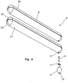
Figure 4 illustrates an exploded isometric view of the embodiment shown inFigure 1 ; -
Figure 5 illustrates an exploded isometric view of the embodiment shown inFigure 1 ; -
Figure 6a illustrates an exploded isometric view of an apparatus in accordance with another embodiment of the present invention; -
Figure 6b illustrates an end view of an apparatus in accordance with another embodiment of the present invention; and -
Figure 7 illustrates a side view of an apparatus, in accordance with another embodiment of the present invention. - With reference to the figures there is shown an apparatus A for inserting, in use, into a space or gap between two objects, for example, a vehicular seat and another object or structure, in particular such as the transmission tunnel, central console or coin tidy. In this way, a space or gap may be filled and small objects prevented from falling into this space.
- The apparatus A thereby comprises an elongate body formed from an
inflatable bladder 10, and further comprises anouter sleeve 6 located over theinner bladder 10, the body arranged to fit into the space or gap. In this way, the apparatus A may be available in a plurality of sizes according to make and model. In some embodiments of the present invention, the body is adjustable in diameter so as to expand or contract to fit the space or gap. - Embodiments of the apparatus A comprise inflation means so as to minimise size for non-use, transport or storage. The apparatus A may therefore comprise a laterally expandable body which is elongate in shape, so as to effectively fill the narrow space or gap defined between a seat and the central feature of a standard vehicle such as a car.
- In the first pictured embodiment, inflation means are provided in the form of an
inflation mechanism 1, comprising a manual rubber orelastomer pump bulb 3 situated on a conduit in the form of aflexible tube 5, which may be screwed into acollar 9 on the bladder, and depending from the bottom face of the body, adjacent an end. Thecollar 9 may be formed from any or any combination of a plastics, PVC, metal or metal alloy material. Thisinflation mechanism 1 comprises arelease valve mechanism 4 bonded directly into theinflation tube 5 which is turned to release the air and anair inlet 14. - In the second pictured embodiment, the inflation mechanism comprises a
manual bulb 33 withgrip pads 35, and atube 34 connection to thebladder 37, as well as aninflation valve 11. - In other embodiments of the present invention, the inflation mechanism may comprise a self-inflation valve, wherein the bladder is biased to open.
- In some embodiments, the enlargement mechanism may be combined with or complementary to a length adjustment means.
- The apparatus A therefore comprises an elongate body sized to fit between a front seat and centre console of a vehicle and in some embodiments adjustable in size.
- The first pictured embodiment provides an
inflatable bladder 10 which can be placed down the side of the seat or seats to prevent objects from passing and falling down. Finishes and covers 6 may help the apparatus A blend in with the vehicle's interior styling. In some embodiments, the apparatus A may comprise a displaceable cover system suitable for customising the aesthetics of the apparatus A, for example as shown in the second embodiment. - In its deflated state, the bladder can be stored flat or may be rolled up.
- The body as pictured comprises a top and bottom face, and sides connecting the top and bottom, and two
ends end 8 is envisaged to be towards the rear of the seat in use. - The top and bottom may be identical in some embodiments. In other embodiments, the top may provide a substantially flat top, so as to enable a user to use the top as a useful surface.
- In the pictured embodiment, the bladder and cover are formed of a plurality of pieces, wherein the cover comprises an external ridge or
seam 15 and plural end sections 16. The seam may combine with a lozenge shape in section to the body in limiting rotation, wherein the seam catches on the surrounding objects or surfaces. In some embodiments, the seam may be formed in a separate or resiliently deformable material or format, for example comprising a silicone braiding. - In a preferred embodiment, and as illustrated in
Figure 7 , thecover 6 may be provided in the form of a sleeve member, in which the bladder may be at least partially located. Typically, thecover 6 is elongate and includes at least a first aperture orslot 71 through which thebladder 10 may be inserted. For ease of use, thebladder 10 is arranged to be inserted into thecover 6 when in a deflated configuration. Theslot 71 may be located along part of alongitudinal edge 73 of thecover 6, at or adjacent a first end thereof. In some embodiments of the present invention, twoslots cover 6, each located along part of the same longitudinal edge of the sleeve/cover, at or adjacent opposing ends thereof. The provision of at least two slots, 71, 75 enables a user to insert or feed theinflatable bladder 10 through afirst slot 71, and either as it is expanding/inflating or prior thereto, can use thesecond slot 75 to insert their own fingers or hand etc. and grip the leading end of thebladder 10, pulling it along the length of thecover 6 to ensure it expands and fills thecover 6 correctly as it is inflated. - In some embodiments, the top may be provided with a surface arranged for use, for example comprising indentations, hook and loop material such as Velcro (RTM) or substantially rigid material or coating.
- In some embodiments, the bladder may comprise two differing materials or formations, between top 15 half and bottom 17 half, so as to provide for differing characteristics. For example, in this way the top surface or
half 19 may be more resistant and/or less prone to deformation or bending, whereas thelower half 17 may be more resiliently deformable so as to allow deformation to accommodate surroundings better. - In some embodiments, this top may be provided by a separate or separable part, which part may comprise a substantially rigid cover, for example including pockets or a cup holder.
- In some embodiments, the cover may be leather or flexible, and comprises an outer sleeve for the inflatable body.
- Multiple outer sleeve covers may be available to match car interiors, for a more premium finish. Automotive style stitching is employed to match with car interiors. The pictured embodiment's bladder has a flocked outer finish cover and so provides a soft touch feel.
- + Simple, inflatable design.
- + It can conform to any gap between the car seat and the centre console.
- + Easy interaction pump, placeable at a position where it is easy to use.
- + Optional covers to complement styling.
- In use, a user would:
Slot the device into the gap between the seat and the centre console. - Pump until has filled the void, blocking items from falling under the seat.
- To suit personal preference, the pump can be positioned to front or rear of seat in use.
- The embodiments may comprise exterior vinyl covers with automotive style stitching to help tie the product aesthetics to its environment. Stretchy vinyls are available in a variety of different styles, colours and finishes to match up with any car interior. As the bladder inflates, the exterior vinyl expands with it.
- In the second embodiment,
displaceable vinyl sections 36 reveal air release valve. - The bottom panel advantageously houses a semi rigid spine. The Velcro (RTM)
pads
Claims (11)
- An apparatus (A) arranged to be inserted between a side of a seat and a central console of a vehicle, in use, said apparatus including an inflatable bladder (10); further including inflation means (1) provided associated with the bladder (10) to permit selectable inflation and deflation of the apparatus by a user; and characterized in that said inflation means (1) comprise a bulb pump member which includes a bulb body (3), air inlet means (14), air outlet means, and a valve member (4) to permit deflation of the inflatable bladder (10), and wherein the apparatus further includes a sleeve member (6), and said inflatable bladder (10) is provided to be located within, or at least partially within, said sleeve member (6).
- An apparatus (A) according to claim 1, wherein the inflatable bladder (10) forms an elongate member, laterally inflatable, with respect to a longitudinal axis thereof.
- An apparatus (A) according to claim 1, wherein said inflatable bladder (10) is formed from an expandable and/or elastic material.
- An apparatus (A) according to claim 1, wherein said bladder (10) is inflatable to a size as required by a user to fit a gap between the side of a seat and the central console of a vehicle.
- An apparatus (A) according to claim 1, wherein said sleeve member (6) comprises an elongate member, including at least one aperture (71), through which said inflatable bladder (10) is arranged to be inserted.
- An apparatus (A) according to claim 1, wherein said sleeve member (6) is expandable upon inflation of the inflatable bladder (10).
- An apparatus (A) according to claim 1, wherein said sleeve member (6) is provided with an exterior colour, texture and/or material to match that of the upholstery or material of the vehicle in which the apparatus is to be located.
- An apparatus (A) according to claim 4, wherein at least one aperture (71) is located at or adjacent a first end of the sleeve member (6).
- An apparatus (A) according to claim 8, wherein said sleeve member (6) includes at least two apertures (71, 75), located at or adjacent first and second opposing ends of the sleeve member (6).
- A method of manufacturing an apparatus (A) arranged to be inserted between a side of a seat and a central console of a vehicle, in use, said method including the steps of: forming and proving an inflatable bladder (10); providing inflation means (1) to be associated with the bladder to permit selectable inflation and deflation of the apparatus by a user, and characterized in that said inflation means are formed having a bulb pump member which includes a bulb body (3), air inlet means (14) and air outlet means, and a valve member (4) to permit deflation of the inflatable bladder (10), and wherein a sleeve member (6) is formed and said inflatable bladder (10) is provided to be located within, or at least partially within, said sleeve member (6).
- A method of using an apparatus (A) arranged to be inserted between a side of a seat and a central console of a vehicle, in use, said method including the steps of: providing an apparatus (A) as described in claims 1-9; locating the inflatable bladder (10) in a gap between a side of a seat and the central console of the vehicle, as required; and actuating the inflation means (1) to inflate the bladder (10) to fill the gap, as required.
Applications Claiming Priority (2)
| Application Number | Priority Date | Filing Date | Title |
|---|---|---|---|
| GBGB1614671.4A GB201614671D0 (en) | 2016-08-26 | 2016-08-26 | A device |
| PCT/GB2017/052464 WO2018037215A1 (en) | 2016-08-26 | 2017-08-21 | Inflatable device |
Publications (2)
| Publication Number | Publication Date |
|---|---|
| EP3504087A1 EP3504087A1 (en) | 2019-07-03 |
| EP3504087B1 true EP3504087B1 (en) | 2022-08-03 |
Family
ID=57119949
Family Applications (1)
| Application Number | Title | Priority Date | Filing Date |
|---|---|---|---|
| EP17761556.4A Not-in-force EP3504087B1 (en) | 2016-08-26 | 2017-08-21 | Inflatable device |
Country Status (3)
| Country | Link |
|---|---|
| EP (1) | EP3504087B1 (en) |
| GB (1) | GB201614671D0 (en) |
| WO (1) | WO2018037215A1 (en) |
Families Citing this family (1)
| Publication number | Priority date | Publication date | Assignee | Title |
|---|---|---|---|---|
| US10479244B1 (en) * | 2018-03-28 | 2019-11-19 | Amos Issac | Automobile passenger compartment console insert |
Citations (1)
| Publication number | Priority date | Publication date | Assignee | Title |
|---|---|---|---|---|
| US20080283565A1 (en) * | 2007-05-16 | 2008-11-20 | Jeffrey Simon | Apparatus for closing gaps |
Family Cites Families (11)
| Publication number | Priority date | Publication date | Assignee | Title |
|---|---|---|---|---|
| DE2165261A1 (en) * | 1971-12-29 | 1973-07-12 | Hans Bauer | LEG REST FOR DRIVERS |
| GB2091842B (en) * | 1981-01-20 | 1985-07-10 | Forsyth Robert M | Protective cover for fender |
| DE4121378A1 (en) * | 1990-07-10 | 1992-01-16 | Volkswagen Ag | LUGGAGE COVER |
| GB2281718B (en) * | 1993-09-10 | 1997-02-26 | Zone Products Limited | Vehicle body protector |
| DE4437394C2 (en) * | 1994-10-19 | 1997-11-27 | Mauser Office Gmbh | Upholstered seating, in particular a chair with a padded backrest |
| DE102007026366A1 (en) * | 2007-06-06 | 2008-12-11 | GM Global Technology Operations, Inc., Detroit | Inflatable partition between automobile luggage space and passenger compartment |
| DE102007033987A1 (en) * | 2007-07-19 | 2009-01-22 | Wolfgang Suttner | Pillow i.e. travel pillow, for supporting head in sitting position in transportation unit i.e. aircraft, has connecting unit provided for blowing up cavity, and formed as manually operable pump such as bellows or rubber ball |
| GB2457728A (en) * | 2008-02-23 | 2009-08-26 | Richard Gerarde Beckett | Car protector |
| WO2013039497A1 (en) * | 2011-09-14 | 2013-03-21 | Wallyhoo, Inc. | Rear seat divider for motor vehicle |
| AU2014204492A1 (en) * | 2013-07-18 | 2015-02-05 | Miles, Shane Robert MR | Seat cover |
| SK289225B6 (en) * | 2015-09-16 | 2024-08-14 | Ing. Dušenka Jozef | Seat for motor vehicle, especially for motor vehicle with open body, seat cover |
-
2016
- 2016-08-26 GB GBGB1614671.4A patent/GB201614671D0/en not_active Ceased
-
2017
- 2017-08-21 EP EP17761556.4A patent/EP3504087B1/en not_active Not-in-force
- 2017-08-21 WO PCT/GB2017/052464 patent/WO2018037215A1/en not_active Ceased
Patent Citations (1)
| Publication number | Priority date | Publication date | Assignee | Title |
|---|---|---|---|---|
| US20080283565A1 (en) * | 2007-05-16 | 2008-11-20 | Jeffrey Simon | Apparatus for closing gaps |
Also Published As
| Publication number | Publication date |
|---|---|
| WO2018037215A1 (en) | 2018-03-01 |
| GB201614671D0 (en) | 2016-10-12 |
| EP3504087A1 (en) | 2019-07-03 |
Similar Documents
| Publication | Publication Date | Title |
|---|---|---|
| US8267291B2 (en) | Apparatus for closing gaps | |
| US8672401B2 (en) | Vehicle seat side bolster pillow and barrier | |
| US8128167B2 (en) | Seat cushion extension mechanism | |
| US4789202A (en) | Inflatable seat cushion | |
| US8360519B1 (en) | Temporary seat-top storage device | |
| US8678511B2 (en) | Adjustable automobile air cushion apparatus | |
| US20150253813A1 (en) | Soft mount for tablet format electronic devices | |
| CN105936225A (en) | Movable inserts for concealing child safety seat anchors in a vehicle | |
| CN105922965A (en) | Vehicle impact energy absorber | |
| CN106314350A (en) | Airbag assembly and vehicle seat provided with same | |
| US20080029565A1 (en) | Back pack including front pouch | |
| EP3504087A1 (en) | Inflatable device | |
| US20040038603A1 (en) | River float device for safely supporting users | |
| US10906438B2 (en) | Integrated second row load floor air mattress | |
| US20040207245A1 (en) | Seatbelt buckle stabilizing device | |
| US6382730B1 (en) | Seat belt shoulder harness retainer device | |
| US20180055233A1 (en) | Resting surfaces for vehicle occupants | |
| EP3517356B1 (en) | Motorised vehicle with an airbed | |
| CN208498327U (en) | Seat-assembly | |
| US8458834B1 (en) | Travel pillow | |
| CN106394335A (en) | Folding inflatable child seat built in passenger seat | |
| US6496994B1 (en) | Back support | |
| US20070205650A1 (en) | Seat Belt Buckle Extender | |
| CN204210339U (en) | Rest the head on, there is the seat of this headrest and there is the vehicle of this seat | |
| CN103179881A (en) | Temporary seat-top storage device |
Legal Events
| Date | Code | Title | Description |
|---|---|---|---|
| STAA | Information on the status of an ep patent application or granted ep patent |
Free format text: STATUS: UNKNOWN |
|
| STAA | Information on the status of an ep patent application or granted ep patent |
Free format text: STATUS: THE INTERNATIONAL PUBLICATION HAS BEEN MADE |
|
| PUAI | Public reference made under article 153(3) epc to a published international application that has entered the european phase |
Free format text: ORIGINAL CODE: 0009012 |
|
| STAA | Information on the status of an ep patent application or granted ep patent |
Free format text: STATUS: REQUEST FOR EXAMINATION WAS MADE |
|
| 17P | Request for examination filed |
Effective date: 20190211 |
|
| AK | Designated contracting states |
Kind code of ref document: A1 Designated state(s): AL AT BE BG CH CY CZ DE DK EE ES FI FR GB GR HR HU IE IS IT LI LT LU LV MC MK MT NL NO PL PT RO RS SE SI SK SM TR |
|
| AX | Request for extension of the european patent |
Extension state: BA ME |
|
| DAV | Request for validation of the european patent (deleted) | ||
| DAX | Request for extension of the european patent (deleted) | ||
| STAA | Information on the status of an ep patent application or granted ep patent |
Free format text: STATUS: EXAMINATION IS IN PROGRESS |
|
| 17Q | First examination report despatched |
Effective date: 20210617 |
|
| GRAP | Despatch of communication of intention to grant a patent |
Free format text: ORIGINAL CODE: EPIDOSNIGR1 |
|
| STAA | Information on the status of an ep patent application or granted ep patent |
Free format text: STATUS: GRANT OF PATENT IS INTENDED |
|
| INTG | Intention to grant announced |
Effective date: 20220302 |
|
| GRAS | Grant fee paid |
Free format text: ORIGINAL CODE: EPIDOSNIGR3 |
|
| GRAA | (expected) grant |
Free format text: ORIGINAL CODE: 0009210 |
|
| STAA | Information on the status of an ep patent application or granted ep patent |
Free format text: STATUS: THE PATENT HAS BEEN GRANTED |
|
| AK | Designated contracting states |
Kind code of ref document: B1 Designated state(s): AL AT BE BG CH CY CZ DE DK EE ES FI FR GB GR HR HU IE IS IT LI LT LU LV MC MK MT NL NO PL PT RO RS SE SI SK SM TR |
|
| REG | Reference to a national code |
Ref country code: AT Ref legal event code: REF Ref document number: 1508501 Country of ref document: AT Kind code of ref document: T Effective date: 20220815 Ref country code: CH Ref legal event code: EP |
|
| REG | Reference to a national code |
Ref country code: DE Ref legal event code: R096 Ref document number: 602017060213 Country of ref document: DE |
|
| REG | Reference to a national code |
Ref country code: IE Ref legal event code: FG4D |
|
| REG | Reference to a national code |
Ref country code: LT Ref legal event code: MG9D |
|
| REG | Reference to a national code |
Ref country code: NL Ref legal event code: MP Effective date: 20220803 |
|
| PG25 | Lapsed in a contracting state [announced via postgrant information from national office to epo] |
Ref country code: SE Free format text: LAPSE BECAUSE OF FAILURE TO SUBMIT A TRANSLATION OF THE DESCRIPTION OR TO PAY THE FEE WITHIN THE PRESCRIBED TIME-LIMIT Effective date: 20220803 Ref country code: RS Free format text: LAPSE BECAUSE OF FAILURE TO SUBMIT A TRANSLATION OF THE DESCRIPTION OR TO PAY THE FEE WITHIN THE PRESCRIBED TIME-LIMIT Effective date: 20220803 Ref country code: PT Free format text: LAPSE BECAUSE OF FAILURE TO SUBMIT A TRANSLATION OF THE DESCRIPTION OR TO PAY THE FEE WITHIN THE PRESCRIBED TIME-LIMIT Effective date: 20221205 Ref country code: NO Free format text: LAPSE BECAUSE OF FAILURE TO SUBMIT A TRANSLATION OF THE DESCRIPTION OR TO PAY THE FEE WITHIN THE PRESCRIBED TIME-LIMIT Effective date: 20221103 Ref country code: NL Free format text: LAPSE BECAUSE OF FAILURE TO SUBMIT A TRANSLATION OF THE DESCRIPTION OR TO PAY THE FEE WITHIN THE PRESCRIBED TIME-LIMIT Effective date: 20220803 Ref country code: LV Free format text: LAPSE BECAUSE OF FAILURE TO SUBMIT A TRANSLATION OF THE DESCRIPTION OR TO PAY THE FEE WITHIN THE PRESCRIBED TIME-LIMIT Effective date: 20220803 Ref country code: LT Free format text: LAPSE BECAUSE OF FAILURE TO SUBMIT A TRANSLATION OF THE DESCRIPTION OR TO PAY THE FEE WITHIN THE PRESCRIBED TIME-LIMIT Effective date: 20220803 Ref country code: FI Free format text: LAPSE BECAUSE OF FAILURE TO SUBMIT A TRANSLATION OF THE DESCRIPTION OR TO PAY THE FEE WITHIN THE PRESCRIBED TIME-LIMIT Effective date: 20220803 Ref country code: ES Free format text: LAPSE BECAUSE OF FAILURE TO SUBMIT A TRANSLATION OF THE DESCRIPTION OR TO PAY THE FEE WITHIN THE PRESCRIBED TIME-LIMIT Effective date: 20220803 |
|
| REG | Reference to a national code |
Ref country code: AT Ref legal event code: MK05 Ref document number: 1508501 Country of ref document: AT Kind code of ref document: T Effective date: 20220803 |
|
| PG25 | Lapsed in a contracting state [announced via postgrant information from national office to epo] |
Ref country code: PL Free format text: LAPSE BECAUSE OF FAILURE TO SUBMIT A TRANSLATION OF THE DESCRIPTION OR TO PAY THE FEE WITHIN THE PRESCRIBED TIME-LIMIT Effective date: 20220803 Ref country code: IS Free format text: LAPSE BECAUSE OF FAILURE TO SUBMIT A TRANSLATION OF THE DESCRIPTION OR TO PAY THE FEE WITHIN THE PRESCRIBED TIME-LIMIT Effective date: 20221203 Ref country code: HR Free format text: LAPSE BECAUSE OF FAILURE TO SUBMIT A TRANSLATION OF THE DESCRIPTION OR TO PAY THE FEE WITHIN THE PRESCRIBED TIME-LIMIT Effective date: 20220803 Ref country code: GR Free format text: LAPSE BECAUSE OF FAILURE TO SUBMIT A TRANSLATION OF THE DESCRIPTION OR TO PAY THE FEE WITHIN THE PRESCRIBED TIME-LIMIT Effective date: 20221104 |
|
| REG | Reference to a national code |
Ref country code: CH Ref legal event code: PL |
|
| PG25 | Lapsed in a contracting state [announced via postgrant information from national office to epo] |
Ref country code: SM Free format text: LAPSE BECAUSE OF FAILURE TO SUBMIT A TRANSLATION OF THE DESCRIPTION OR TO PAY THE FEE WITHIN THE PRESCRIBED TIME-LIMIT Effective date: 20220803 Ref country code: RO Free format text: LAPSE BECAUSE OF FAILURE TO SUBMIT A TRANSLATION OF THE DESCRIPTION OR TO PAY THE FEE WITHIN THE PRESCRIBED TIME-LIMIT Effective date: 20220803 Ref country code: LU Free format text: LAPSE BECAUSE OF NON-PAYMENT OF DUE FEES Effective date: 20220821 Ref country code: LI Free format text: LAPSE BECAUSE OF NON-PAYMENT OF DUE FEES Effective date: 20220831 Ref country code: DK Free format text: LAPSE BECAUSE OF FAILURE TO SUBMIT A TRANSLATION OF THE DESCRIPTION OR TO PAY THE FEE WITHIN THE PRESCRIBED TIME-LIMIT Effective date: 20220803 Ref country code: CZ Free format text: LAPSE BECAUSE OF FAILURE TO SUBMIT A TRANSLATION OF THE DESCRIPTION OR TO PAY THE FEE WITHIN THE PRESCRIBED TIME-LIMIT Effective date: 20220803 Ref country code: CH Free format text: LAPSE BECAUSE OF NON-PAYMENT OF DUE FEES Effective date: 20220831 Ref country code: AT Free format text: LAPSE BECAUSE OF FAILURE TO SUBMIT A TRANSLATION OF THE DESCRIPTION OR TO PAY THE FEE WITHIN THE PRESCRIBED TIME-LIMIT Effective date: 20220803 |
|
| REG | Reference to a national code |
Ref country code: BE Ref legal event code: MM Effective date: 20220831 |
|
| REG | Reference to a national code |
Ref country code: DE Ref legal event code: R097 Ref document number: 602017060213 Country of ref document: DE |
|
| PG25 | Lapsed in a contracting state [announced via postgrant information from national office to epo] |
Ref country code: SK Free format text: LAPSE BECAUSE OF FAILURE TO SUBMIT A TRANSLATION OF THE DESCRIPTION OR TO PAY THE FEE WITHIN THE PRESCRIBED TIME-LIMIT Effective date: 20220803 Ref country code: MC Free format text: LAPSE BECAUSE OF FAILURE TO SUBMIT A TRANSLATION OF THE DESCRIPTION OR TO PAY THE FEE WITHIN THE PRESCRIBED TIME-LIMIT Effective date: 20220803 Ref country code: EE Free format text: LAPSE BECAUSE OF FAILURE TO SUBMIT A TRANSLATION OF THE DESCRIPTION OR TO PAY THE FEE WITHIN THE PRESCRIBED TIME-LIMIT Effective date: 20220803 |
|
| PLBE | No opposition filed within time limit |
Free format text: ORIGINAL CODE: 0009261 |
|
| STAA | Information on the status of an ep patent application or granted ep patent |
Free format text: STATUS: NO OPPOSITION FILED WITHIN TIME LIMIT |
|
| PG25 | Lapsed in a contracting state [announced via postgrant information from national office to epo] |
Ref country code: AL Free format text: LAPSE BECAUSE OF FAILURE TO SUBMIT A TRANSLATION OF THE DESCRIPTION OR TO PAY THE FEE WITHIN THE PRESCRIBED TIME-LIMIT Effective date: 20220803 |
|
| 26N | No opposition filed |
Effective date: 20230504 |
|
| PG25 | Lapsed in a contracting state [announced via postgrant information from national office to epo] |
Ref country code: IE Free format text: LAPSE BECAUSE OF NON-PAYMENT OF DUE FEES Effective date: 20220821 |
|
| PG25 | Lapsed in a contracting state [announced via postgrant information from national office to epo] |
Ref country code: SI Free format text: LAPSE BECAUSE OF FAILURE TO SUBMIT A TRANSLATION OF THE DESCRIPTION OR TO PAY THE FEE WITHIN THE PRESCRIBED TIME-LIMIT Effective date: 20220803 |
|
| PG25 | Lapsed in a contracting state [announced via postgrant information from national office to epo] |
Ref country code: BE Free format text: LAPSE BECAUSE OF NON-PAYMENT OF DUE FEES Effective date: 20220831 |
|
| PGFP | Annual fee paid to national office [announced via postgrant information from national office to epo] |
Ref country code: FR Payment date: 20230801 Year of fee payment: 7 Ref country code: DE Payment date: 20230802 Year of fee payment: 7 |
|
| PG25 | Lapsed in a contracting state [announced via postgrant information from national office to epo] |
Ref country code: HU Free format text: LAPSE BECAUSE OF FAILURE TO SUBMIT A TRANSLATION OF THE DESCRIPTION OR TO PAY THE FEE WITHIN THE PRESCRIBED TIME-LIMIT; INVALID AB INITIO Effective date: 20170821 |
|
| PG25 | Lapsed in a contracting state [announced via postgrant information from national office to epo] |
Ref country code: CY Free format text: LAPSE BECAUSE OF FAILURE TO SUBMIT A TRANSLATION OF THE DESCRIPTION OR TO PAY THE FEE WITHIN THE PRESCRIBED TIME-LIMIT Effective date: 20220803 |
|
| PG25 | Lapsed in a contracting state [announced via postgrant information from national office to epo] |
Ref country code: MK Free format text: LAPSE BECAUSE OF FAILURE TO SUBMIT A TRANSLATION OF THE DESCRIPTION OR TO PAY THE FEE WITHIN THE PRESCRIBED TIME-LIMIT Effective date: 20220803 Ref country code: IT Free format text: LAPSE BECAUSE OF FAILURE TO SUBMIT A TRANSLATION OF THE DESCRIPTION OR TO PAY THE FEE WITHIN THE PRESCRIBED TIME-LIMIT Effective date: 20220803 |
|
| PG25 | Lapsed in a contracting state [announced via postgrant information from national office to epo] |
Ref country code: TR Free format text: LAPSE BECAUSE OF FAILURE TO SUBMIT A TRANSLATION OF THE DESCRIPTION OR TO PAY THE FEE WITHIN THE PRESCRIBED TIME-LIMIT Effective date: 20220803 |
|
| PG25 | Lapsed in a contracting state [announced via postgrant information from national office to epo] |
Ref country code: BG Free format text: LAPSE BECAUSE OF FAILURE TO SUBMIT A TRANSLATION OF THE DESCRIPTION OR TO PAY THE FEE WITHIN THE PRESCRIBED TIME-LIMIT Effective date: 20220803 |
|
| PG25 | Lapsed in a contracting state [announced via postgrant information from national office to epo] |
Ref country code: MT Free format text: LAPSE BECAUSE OF FAILURE TO SUBMIT A TRANSLATION OF THE DESCRIPTION OR TO PAY THE FEE WITHIN THE PRESCRIBED TIME-LIMIT Effective date: 20220803 |
|
| PGFP | Annual fee paid to national office [announced via postgrant information from national office to epo] |
Ref country code: GB Payment date: 20240723 Year of fee payment: 8 |
|
| REG | Reference to a national code |
Ref country code: DE Ref legal event code: R119 Ref document number: 602017060213 Country of ref document: DE |
|
| PG25 | Lapsed in a contracting state [announced via postgrant information from national office to epo] |
Ref country code: DE Free format text: LAPSE BECAUSE OF NON-PAYMENT OF DUE FEES Effective date: 20250301 |
|
| PG25 | Lapsed in a contracting state [announced via postgrant information from national office to epo] |
Ref country code: FR Free format text: LAPSE BECAUSE OF NON-PAYMENT OF DUE FEES Effective date: 20240831 |
|
| GBPC | Gb: european patent ceased through non-payment of renewal fee |
Effective date: 20250821 |