EP3503298A1 - Base station antenna for cellular communications - Google Patents
Base station antenna for cellular communications Download PDFInfo
- Publication number
- EP3503298A1 EP3503298A1 EP17210467.1A EP17210467A EP3503298A1 EP 3503298 A1 EP3503298 A1 EP 3503298A1 EP 17210467 A EP17210467 A EP 17210467A EP 3503298 A1 EP3503298 A1 EP 3503298A1
- Authority
- EP
- European Patent Office
- Prior art keywords
- array
- antenna elements
- antenna
- base station
- dual purpose
- Prior art date
- Legal status (The legal status is an assumption and is not a legal conclusion. Google has not performed a legal analysis and makes no representation as to the accuracy of the status listed.)
- Ceased
Links
- 230000010267 cellular communication Effects 0.000 title description 3
- 238000004891 communication Methods 0.000 claims abstract description 56
- 230000009977 dual effect Effects 0.000 claims abstract description 35
- 230000005540 biological transmission Effects 0.000 claims abstract description 32
- 238000005516 engineering process Methods 0.000 claims description 10
- 230000005855 radiation Effects 0.000 claims description 7
- 239000002131 composite material Substances 0.000 claims description 4
- 238000000034 method Methods 0.000 description 4
- 238000012545 processing Methods 0.000 description 3
- 238000013461 design Methods 0.000 description 2
- 239000002184 metal Substances 0.000 description 2
- 230000006978 adaptation Effects 0.000 description 1
- 238000003491 array Methods 0.000 description 1
- 230000001419 dependent effect Effects 0.000 description 1
- 230000005571 horizontal transmission Effects 0.000 description 1
- 238000002372 labelling Methods 0.000 description 1
- 238000012986 modification Methods 0.000 description 1
- 230000004048 modification Effects 0.000 description 1
- 238000000926 separation method Methods 0.000 description 1
Images


Classifications
-
- H—ELECTRICITY
- H01—ELECTRIC ELEMENTS
- H01Q—ANTENNAS, i.e. RADIO AERIALS
- H01Q1/00—Details of, or arrangements associated with, antennas
- H01Q1/12—Supports; Mounting means
- H01Q1/22—Supports; Mounting means by structural association with other equipment or articles
- H01Q1/24—Supports; Mounting means by structural association with other equipment or articles with receiving set
- H01Q1/241—Supports; Mounting means by structural association with other equipment or articles with receiving set used in mobile communications, e.g. GSM
- H01Q1/246—Supports; Mounting means by structural association with other equipment or articles with receiving set used in mobile communications, e.g. GSM specially adapted for base stations
-
- H—ELECTRICITY
- H01—ELECTRIC ELEMENTS
- H01Q—ANTENNAS, i.e. RADIO AERIALS
- H01Q21/00—Antenna arrays or systems
- H01Q21/06—Arrays of individually energised antenna units similarly polarised and spaced apart
- H01Q21/061—Two dimensional planar arrays
-
- H—ELECTRICITY
- H01—ELECTRIC ELEMENTS
- H01Q—ANTENNAS, i.e. RADIO AERIALS
- H01Q5/00—Arrangements for simultaneous operation of antennas on two or more different wavebands, e.g. dual-band or multi-band arrangements
- H01Q5/40—Imbricated or interleaved structures; Combined or electromagnetically coupled arrangements, e.g. comprising two or more non-connected fed radiating elements
- H01Q5/42—Imbricated or interleaved structures; Combined or electromagnetically coupled arrangements, e.g. comprising two or more non-connected fed radiating elements using two or more imbricated arrays
Definitions
- the present invention relates to a base station antenna for cellular communications.
- a sector antenna is used for radio frequency communications.
- three sector antennas are angularly arranged with the sector antennas pointing in different spatial directions.
- MIMO multiple-in multiple-out
- the disclosure relates to a dual purpose base station antenna for handling beamforming communications and non-beamforming, for example traditional radio frequency communications which are usually handled by one or more sector antenna, communications in a communication cell
- the dual purpose base station antenna comprising: an antenna mounting frame; a first array of antenna elements arranged on the antenna mounting frame, the first array of antenna elements being capable of generating a radio frequency transmission signal for non-beamforming communications; and a second array of antenna elements attached to the antenna mounting frame, the second array of antenna elements being capable of generating a transmission beam for beamforming communications, wherein the second array of antenna elements at least partially intermeshes with the first array of antenna elements.
- the intermeshing is achieved by alternately arranging antenna elements of the first and the second array next to each other and/or above each other. Thereby, the radiating antenna aperture can efficiently be obtained. Moreover, the intermeshed antenna elements can jointly be used either for sector-like communications or for beamforming communications.
- the first array of antenna elements forms a sector antenna with a sector-shaped horizontal radiation pattern for generating the radio frequency transmission signal
- the second array of antenna elements forms a multiple input multiple output (MIMO) antenna with a beam-shaped horizontal radiation pattern.
- MIMO multiple input multiple output
- the first array can form a sector antenna for communications with a fix sector-like horizontal radiation pattern.
- the dual purpose base station antenna comprises two further first arrays of antenna elements arranged in an angular fashion for omnidirectional communications.
- the first array of antenna elements and the second array of antenna elements are independently and/or simultaneously excited.
- beamforming and non-beamforming communications such as sector-like radiation can be handled independently from each other. Thereby, the number of communicating user entities can be increased.
- the first array of antenna elements and the second array of antenna elements jointly form a composite array of antenna elements, the composite array of antenna elements being capable of generating a second transmission beam with reduced beam width compared to the transmission beam generated only be the second array of antenna elements.
- the reduced width or increased beam separation can be obtained due to the increased number of antenna elements available for beamforming.
- the first array of antenna elements and the second array of antenna elements share common antenna elements, the common antenna elements being assigned to the first array for generating the radio frequency transmission signal, or being assigned to the second array of antenna elements for generating the transmission beam.
- the available antenna elements can more efficiently be used for communications.
- the second array of antenna elements is arranged on a carrier, in particular on a dielectric carrier, the carrier being attached to the antenna mounting frame such that the intermeshing antenna elements of the second array of antenna elements do not overlay the antenna elements of the first array of antenna elements.
- existing sector antennas can be provided with additional beamforming functionality for beamforming communications.
- the carrier overlays the first array of antenna elements. This enables a space-efficient antenna design.
- the second array of antenna elements is arranged on the antenna mounting frame, wherein antenna elements of the second array of antenna elements and elements of the first array of antenna elements are alternately arranged on the antenna mounting frame.
- the available antenna space can more efficiently be used.
- the antenna elements can be arranged within the same plane which simplifies controlling antenna elements for e.g. generating a transmission beam.
- the antenna mounting frame comprises a widened portion for accommodating the second array of antenna elements.
- the second array of antenna elements can be arranged in a plane suitable for accommodating a plurality of antenna elements, e.g. 64, according to the 5G communication technology.
- the dual purpose base station antenna comprises a third array of antenna elements being capable of beamforming communications, wherein the third array of antenna elements is arranged below or above the second array of antenna elements.
- the third array of antenna elements can be tilted downwards for directing transmission beams more easily towards e.g. urban areas located below the antenna, or tilted upwards for beamforming communications with e.g. drones.
- the third array of antenna elements at least partially intermeshes with the first array of antenna elements.
- the first array of antenna elements forms a sector antenna
- the second array of antenna elements forms a multiple input multiple output (MIMO) beamforming antenna.
- MIMO multiple input multiple output
- the first array of antenna elements is configured for communications in a first frequency range, in particular 800 MHz, 0.8, 0.9, 1.8 GHz and 2.1 GHz
- the second array of antenna elements is configured for communications in a second frequency range, in particular 3.4 to 3.8 GHz, or 24.25 to 29.5 GHz or 31.8 to 33.4GHz or 37 to 40 GHz or 57 to 77 GHz, wherein the first frequency range at least partly differs from the second frequency range.
- the disclosure relates to a MIMO base station system, comprising: the dual purpose base station antenna according to the first aspect; and a MIMO base station for cellular communications, wherein the MIMO base station is configured to excite the first antenna array to generate the a radio frequency transmission signal for non-beamforming communications, and to excite the second array of antenna elements to transmit the transmission beam or to receive a reception beam from a user equipment or a user entity.
- the MIMO base station system can in this way be also deployed for handling communications without beamforming. Thereby, radio access can be provided to user entities being capable and being non-capable of beamforming.
- the dual purpose base station antenna and the MIMO base station are configured for communicating according to one of the following communication technologies: GSM, LTE, LTE-A, UMTS, HSPA, 3GPP, in particular 3GPP NR, New Radio, 5G or IEEE radio systems such as Wireless LAN, WiGig, or any of the evolutions and successors of these technologies.
- a disclosure in connection with a described method may also hold true for a corresponding device or system configured to perform the method and vice versa.
- a corresponding device may include a unit to perform the described method step, even if such unit is not explicitly described or illustrated in the figures.
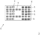
- Fig. 1 shows a dual purpose base station antenna 100 for handling beamforming communications and non-beamforming communications in a communication cell
- the dual purpose base station antenna comprising an antenna mounting frame 102, being e.g. formed form metal, metal mesh or plastic, a first array of antenna elements 101 arranged on the antenna mounting frame 102, the first array of antenna elements 101 being capable of generating a radio frequency transmission signal for non-beamforming communications; and a second array of antenna elements 103 attached to the antenna mounting frame 102, the second array of antenna elements 103 being capable of generating a transmission beam for beamforming communications, wherein the second array of antenna elements 103 at least partially intermeshes with the first array of antenna elements 101.
- the second array of antenna elements 103 is arranged on the antenna mounting frame 102, wherein antenna elements of the second array of antenna elements 103 and elements of the first array of antenna elements 101 are alternately arranged on the antenna mounting frame 102, thereby intermeshing with each other.
- the antenna mounting frame 102 comprises a widened portion 104 for accommodating the second array of antenna elements 103.
- the antenna mounting frame 102 can have a constant width.
- the second array of antenna elements 103 is arranged on a carrier 107, in particular on a dielectric carrier, the carrier 107 being attached to the antenna mounting frame 102 such that the intermeshing antenna elements of the second array of antenna elements 103 do not overlay the antenna elements of the first array of antenna elements 101.
- the antenna mounting frame 102 is provided for mounting the dual purpose base station antenna 100 e.g. on a roof of a building or on a mast.
- Fig. 2 shows the dual purpose base station antenna 100 according to an example, comprising a third array of antenna elements 109 being capable of beamforming communications, wherein the third array of antenna elements 109 is arranged below or above the second array of antenna elements 103.
- the third array of antenna elements 109 at least partially intermeshes with the first array of antenna elements 101.
- the third array of antenna elements 109 can be used for beamforming towards areas located below the dual purpose base station antenna 100, whereas the first array of antenna elements 101 can be used for beamforming towards areas located above the dual purpose base station antenna 100, for example for drone communications.
- the third array of antenna elements 109 can be deployed correspondingly to the deployment of the first array of antenna elements 101. Therefore, the description relating to the first array of antenna elements 101 also applies to the third array of antenna elements 109.
- Fig. 3 shows the dual purpose base station antenna 100 according to an example, where the first array of antenna elements 101 and the second array of antenna elements 103 share common antenna elements 105, the common antenna elements 105 being assigned to the first array of antenna elements 101 for generating the radio frequency transmission signal, or being assigned to the second array of antenna elements 103 for generating the transmission beam.
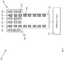
- Fig. 4 shows an example of a MIMO base station system 200, comprising a MIMO base station 201 and the dual purpose base station antenna 100.
- the MIMO base station 201 is configured to excite the first array of antenna elements 101 to generate the a radio frequency transmission signal for non-beamforming communications, and to excite the second array of antenna elements 103 to transmit the transmission beam or to receive a reception beam from a user equipment or a user entity.
- the MIMO base station 201 can be configured for communicating according to one of the following communication technologies: GSM, LTE, LTE-A, UMTS, HSPA, 3GPP, in particular 3GPP NR, New Radio, 5G or IEEE radio systems such as Wireless LAN, WiGig, or any of the evolutions and successors of these technologies.
- the MIMO base station 201 can generate the respective transmission beam using a beamforming codebook according to a MIMO communication technology in order to generate a steering signal for steering the first array of antenna elements 101 and/or the third array of antenna elements 109.
- the codebook can for example indicate an amplitude and/or a phase of a signal driving the respective antenna element or several antenna elements to generate the spatially directed beam.
- the codebook can have an entry 1 + j1 defining an amplitude and a phase of a complex signal.
- the steering signal can indicate the phase. Thereby, a spatially directed transmission beam can be generated, or, conversely, a spatially directed reception beam can be received.
Landscapes
- Physics & Mathematics (AREA)
- Electromagnetism (AREA)
- Engineering & Computer Science (AREA)
- Computer Networks & Wireless Communication (AREA)
- Variable-Direction Aerials And Aerial Arrays (AREA)
- Mobile Radio Communication Systems (AREA)
Abstract
The invention relates to a dual purpose base station antenna (100) for handling beamforming communications and non-beamforming communications in a communication cell, the dual purpose base station antenna comprising: an antenna mounting frame (102); a first array of antenna elements (101) arranged on the antenna mounting frame (102), the first array of antenna elements (101) being capable of generating a radio frequency transmission signal for non-beamforming communications; and a second array of antenna elements (103) attached to the antenna mounting frame (102), the second array of antenna elements (103) being capable of generating a transmission beam for beamforming communications, wherein the second array of antenna elements (103) at least partially intermeshes with the first array of antenna elements (101).
Description
- In general, the present invention relates to a base station antenna for cellular communications.
- In a conventional communication scenario, e.g. according to the LTE communication technology, a sector antenna is used for radio frequency communications. In order to generate an omnidirectional, horizontal transmission pattern, usually three sector antennas are angularly arranged with the sector antennas pointing in different spatial directions.
- With the upcoming 5G technologies, beamforming communications in multiple-in multiple-out (MIMO) fashion is increasingly important. Unlike a sector radiation pattern of a sector antenna, a transmission beam for beamforming communications can be steered towards different directions in order to exploit spatial diversity for more efficiently exploiting the available communication resources.
- In order to support both, traditional radio frequency communications and beamforming communications, usually two separate antennas must be provided. However, the available space for mounting further antennas is limited. There is therefore a need for a more efficient antenna design concept.
- It is therefore an object of the disclosure to provide an improved base station antenna, which is capable of simultaneously handling traditional radio frequency communications and beamforming communications.
- The foregoing and other objects are achieved by the subject matter of the independent claims. Further implementation forms are apparent from the dependent claims, the description and the figures.
- According to a first aspect, the disclosure relates to a dual purpose base station antenna for handling beamforming communications and non-beamforming, for example traditional radio frequency communications which are usually handled by one or more sector antenna, communications in a communication cell, the dual purpose base station antenna comprising: an antenna mounting frame; a first array of antenna elements arranged on the antenna mounting frame, the first array of antenna elements being capable of generating a radio frequency transmission signal for non-beamforming communications; and a second array of antenna elements attached to the antenna mounting frame, the second array of antenna elements being capable of generating a transmission beam for beamforming communications, wherein the second array of antenna elements at least partially intermeshes with the first array of antenna elements.
- The intermeshing is achieved by alternately arranging antenna elements of the first and the second array next to each other and/or above each other. Thereby, the radiating antenna aperture can efficiently be obtained. Moreover, the intermeshed antenna elements can jointly be used either for sector-like communications or for beamforming communications.
- According to an embodiment, the first array of antenna elements forms a sector antenna with a sector-shaped horizontal radiation pattern for generating the radio frequency transmission signal, and the second array of antenna elements forms a multiple input multiple output (MIMO) antenna with a beam-shaped horizontal radiation pattern.
- The first array can form a sector antenna for communications with a fix sector-like horizontal radiation pattern.
- According to an example, the dual purpose base station antenna comprises two further first arrays of antenna elements arranged in an angular fashion for omnidirectional communications.
- According to an example, the first array of antenna elements and the second array of antenna elements are independently and/or simultaneously excited.
- Therefore, beamforming and non-beamforming communications such as sector-like radiation can be handled independently from each other. Thereby, the number of communicating user entities can be increased.
- According to an example, the first array of antenna elements and the second array of antenna elements jointly form a composite array of antenna elements, the composite array of antenna elements being capable of generating a second transmission beam with reduced beam width compared to the transmission beam generated only be the second array of antenna elements.
- The reduced width or increased beam separation can be obtained due to the increased number of antenna elements available for beamforming.
- According to an example, the first array of antenna elements and the second array of antenna elements share common antenna elements, the common antenna elements being assigned to the first array for generating the radio frequency transmission signal, or being assigned to the second array of antenna elements for generating the transmission beam.
- Thereby, the available antenna elements can more efficiently be used for communications.
- According to an example, the second array of antenna elements is arranged on a carrier, in particular on a dielectric carrier, the carrier being attached to the antenna mounting frame such that the intermeshing antenna elements of the second array of antenna elements do not overlay the antenna elements of the first array of antenna elements.
- In this way, e.g. existing sector antennas can be provided with additional beamforming functionality for beamforming communications.
- According to an example, the carrier overlays the first array of antenna elements. This enables a space-efficient antenna design.
- According to an example, the second array of antenna elements is arranged on the antenna mounting frame, wherein antenna elements of the second array of antenna elements and elements of the first array of antenna elements are alternately arranged on the antenna mounting frame.
- Thereby, the available antenna space can more efficiently be used. Moreover, the antenna elements can be arranged within the same plane which simplifies controlling antenna elements for e.g. generating a transmission beam.
- According to an example, the antenna mounting frame comprises a widened portion for accommodating the second array of antenna elements. Thereby, the second array of antenna elements can be arranged in a plane suitable for accommodating a plurality of antenna elements, e.g. 64, according to the 5G communication technology.
- According to an example, the dual purpose base station antenna comprises a third array of antenna elements being capable of beamforming communications, wherein the third array of antenna elements is arranged below or above the second array of antenna elements.
- Thereby, another transmission beam can be generated. Moreover, the third array of antenna elements can be tilted downwards for directing transmission beams more easily towards e.g. urban areas located below the antenna, or tilted upwards for beamforming communications with e.g. drones.
- According to an example, the third array of antenna elements at least partially intermeshes with the first array of antenna elements. Thereby, the above mentioned advantages can be achieved in connection with the third array of elements as described above.
- According to an example, the first array of antenna elements forms a sector antenna, and the second array of antenna elements forms a multiple input multiple output (MIMO) beamforming antenna.
- According to an example, the first array of antenna elements is configured for communications in a first frequency range, in particular 800 MHz, 0.8, 0.9, 1.8 GHz and 2.1 GHz, and the second array of antenna elements is configured for communications in a second frequency range, in particular 3.4 to 3.8 GHz, or 24.25 to 29.5 GHz or 31.8 to 33.4GHz or 37 to 40 GHz or 57 to 77 GHz, wherein the first frequency range at least partly differs from the second frequency range.
- According to a second aspect, the disclosure relates to a MIMO base station system, comprising: the dual purpose base station antenna according to the first aspect; and a MIMO base station for cellular communications, wherein the MIMO base station is configured to excite the first antenna array to generate the a radio frequency transmission signal for non-beamforming communications, and to excite the second array of antenna elements to transmit the transmission beam or to receive a reception beam from a user equipment or a user entity.
- The MIMO base station system can in this way be also deployed for handling communications without beamforming. Thereby, radio access can be provided to user entities being capable and being non-capable of beamforming.
- According to an example, the dual purpose base station antenna and the MIMO base station are configured for communicating according to one of the following communication technologies: GSM, LTE, LTE-A, UMTS, HSPA, 3GPP, in particular 3GPP NR, New Radio, 5G or IEEE radio systems such as Wireless LAN, WiGig, or any of the evolutions and successors of these technologies.
- Further embodiments of the invention will be described with respect to the following figures, wherein:
-
Figure 1 shows an example of a dual purpose base station antenna; -
Figure 2 shows an example of a dual purpose base station antenna; -
Figure 3 shows an example of a dual purpose base station antenna; and -
Figure 4 shows an example of a base station system. - In the various figures, identical reference signs will be used for identical or at least functionally equivalent features.
- In the following description, reference is made to the accompanying drawings, which form part of the disclosure, and in which are shown, by way of illustration, specific aspects in which the present invention may be placed. It will be appreciated that other aspects may be utilized and structural or logical changes may be made without departing from the scope of the present invention. The following detailed description, therefore, is not to be taken in a limiting sense, as the scope of the present invention is defined by the appended claims.
- For instance, it will be appreciated that a disclosure in connection with a described method may also hold true for a corresponding device or system configured to perform the method and vice versa. For example, if a specific method step is described, a corresponding device may include a unit to perform the described method step, even if such unit is not explicitly described or illustrated in the figures.
- Moreover, in the following detailed description as well as in the claims, embodiments with different functional blocks or processing units are described, which are connected with each other or exchange signals. It will be appreciated that the present invention covers embodiments as well, which include additional functional blocks or processing units that are arranged between the functional blocks or processing units of the embodiments described below.
-
Fig. 1 shows a dual purposebase station antenna 100 for handling beamforming communications and non-beamforming communications in a communication cell, the dual purpose base station antenna comprising anantenna mounting frame 102, being e.g. formed form metal, metal mesh or plastic, a first array ofantenna elements 101 arranged on theantenna mounting frame 102, the first array ofantenna elements 101 being capable of generating a radio frequency transmission signal for non-beamforming communications; and a second array ofantenna elements 103 attached to theantenna mounting frame 102, the second array ofantenna elements 103 being capable of generating a transmission beam for beamforming communications, wherein the second array ofantenna elements 103 at least partially intermeshes with the first array ofantenna elements 101. - As depicted in
Fig. 1 , the second array ofantenna elements 103 is arranged on theantenna mounting frame 102, wherein antenna elements of the second array ofantenna elements 103 and elements of the first array ofantenna elements 101 are alternately arranged on theantenna mounting frame 102, thereby intermeshing with each other. - The
antenna mounting frame 102 comprises a widenedportion 104 for accommodating the second array ofantenna elements 103. However, theantenna mounting frame 102 can have a constant width. - Alternatively, the second array of
antenna elements 103 is arranged on acarrier 107, in particular on a dielectric carrier, thecarrier 107 being attached to theantenna mounting frame 102 such that the intermeshing antenna elements of the second array ofantenna elements 103 do not overlay the antenna elements of the first array ofantenna elements 101. - Both alternatives are depicted in
Fig. 1 . - The
antenna mounting frame 102 is provided for mounting the dual purposebase station antenna 100 e.g. on a roof of a building or on a mast. -
Fig. 2 shows the dual purposebase station antenna 100 according to an example, comprising a third array ofantenna elements 109 being capable of beamforming communications, wherein the third array ofantenna elements 109 is arranged below or above the second array ofantenna elements 103. The third array ofantenna elements 109 at least partially intermeshes with the first array ofantenna elements 101. - The third array of
antenna elements 109 can be used for beamforming towards areas located below the dual purposebase station antenna 100, whereas the first array ofantenna elements 101 can be used for beamforming towards areas located above the dual purposebase station antenna 100, for example for drone communications. - The third array of
antenna elements 109 can be deployed correspondingly to the deployment of the first array ofantenna elements 101. Therefore, the description relating to the first array ofantenna elements 101 also applies to the third array ofantenna elements 109. -
Fig. 3 shows the dual purposebase station antenna 100 according to an example, where the first array ofantenna elements 101 and the second array ofantenna elements 103 sharecommon antenna elements 105, thecommon antenna elements 105 being assigned to the first array ofantenna elements 101 for generating the radio frequency transmission signal, or being assigned to the second array ofantenna elements 103 for generating the transmission beam. -
Fig. 4 shows an example of a MIMObase station system 200, comprising aMIMO base station 201 and the dual purposebase station antenna 100. - The
MIMO base station 201 is configured to excite the first array ofantenna elements 101 to generate the a radio frequency transmission signal for non-beamforming communications, and to excite the second array ofantenna elements 103 to transmit the transmission beam or to receive a reception beam from a user equipment or a user entity. - The
MIMO base station 201 can be configured for communicating according to one of the following communication technologies: GSM, LTE, LTE-A, UMTS, HSPA, 3GPP, in particular 3GPP NR, New Radio, 5G or IEEE radio systems such as Wireless LAN, WiGig, or any of the evolutions and successors of these technologies. - The
MIMO base station 201 can generate the respective transmission beam using a beamforming codebook according to a MIMO communication technology in order to generate a steering signal for steering the first array ofantenna elements 101 and/or the third array ofantenna elements 109. The codebook can for example indicate an amplitude and/or a phase of a signal driving the respective antenna element or several antenna elements to generate the spatially directed beam. For example, the codebook can have an entry 1 + j1 defining an amplitude and a phase of a complex signal. The steering signal can indicate the phase. Thereby, a spatially directed transmission beam can be generated, or, conversely, a spatially directed reception beam can be received. - While a particular feature or aspect of the disclosure may have been disclosed with respect to only one of several implementations or embodiments, such feature or aspect may be combined with one or more other features or aspects of the other implementations or embodiments as may be desired and advantageous for any given or particular application. Furthermore, to the extent that the terms "include", "have", "with", or other variants thereof are used in either the detailed description or the claims, such terms are intended to be inclusive in a manner similar to the term "comprise". Also, the terms "exemplary", "for example" and "e.g." are merely meant as an example, rather than the best or optimal. The terms "coupled" and "connected", along with derivatives may have been used. It should be understood that these terms may have been used to indicate that two elements cooperate or interact with each other regardless of whether they are in direct physical or electrical contact, or they are not in direct contact with each other.
- Although specific aspects have been illustrated and described herein, it will be appreciated by those of ordinary skill in the art that a variety of alternate and/or equivalent implementations may be substituted for the specific aspects shown and described without departing from the scope of the present disclosure. This application is intended to cover any adaptations or variations of the specific aspects discussed herein.
- Although the elements in the following claims are recited in a particular sequence with corresponding labeling, unless the claim recitations otherwise imply a particular sequence for implementing some or all of those elements, those elements are not necessarily intended to be limited to being implemented in that particular sequence.
- Many alternatives, modifications, and variations will be apparent to those skilled in the art in light of the above teachings. Of course, those skilled in the art readily recognize that there are numerous applications of the invention beyond those described herein. While the present invention has been described with reference to one or more particular embodiments, those skilled in the art recognize that many changes may be made thereto without departing from the scope of the present invention. It is therefore to be understood that within the scope of the appended claims and their equivalents, the invention may be practiced otherwise than as specifically described herein.
Claims (15)
- Dual purpose base station antenna (100) for handling beamforming communications and non-beamforming communications in a communication cell, the dual purpose base station antenna comprising:an antenna mounting frame (102);a first array of antenna elements (101) arranged on the antenna mounting frame (102), the first array of antenna elements (101) being capable of generating a radio frequency transmission signal for non-beamforming communications; anda second array of antenna elements (103) attached to the antenna mounting frame (102), the second array of antenna elements (103) being capable of generating a transmission beam for beamforming communications, wherein the second array of antenna elements (103) at least partially intermeshes with the first array of antenna elements (101).
- The dual purpose base station antenna (100) according to claim 1, wherein the first array of antenna elements (101) forms a sector antenna with a sector-shaped horizontal radiation pattern for generating the radio frequency transmission signal, and wherein the second array of antenna elements (103) forms a multiple input multiple output (MIMO) antenna with a beam-shaped horizontal radiation pattern.
- The dual purpose base station antenna (100) according to anyone of the preceding claims, wherein the first array of antenna elements (101) and the second array of antenna elements (103) are independently and/or simultaneously excited.
- The dual purpose base station antenna (100) according to anyone of the preceding claims, wherein the first array of antenna elements (101) and the second array of antenna elements (103) jointly form a composite array of antenna elements (101, 103), the composite array of antenna elements (101, 103) being capable of generating a second transmission beam with reduced beam width compared to the transmission beam generated only be the second array of antenna elements.
- The dual purpose base station antenna (100) according to anyone of the preceding claims, wherein the first array of antenna elements (101) and the second array of antenna elements (103) share common antenna elements (105), the common antenna elements (105) being assigned to the first array of antenna elements (101) for generating the radio frequency transmission signal, or being assigned to the second array of antenna elements (103) for generating the transmission beam.
- The dual purpose base station antenna (100) according to anyone of the preceding claims, wherein the second array of antenna elements (103) is arranged on a carrier (107), in particular on a dielectric carrier, the carrier (107) being attached to the antenna mounting frame (102) such that the intermeshing antenna elements of the second array of antenna elements (103) do not overlay the antenna elements of the first array of antenna elements (101).
- The dual purpose base station antenna (100) according to claim 6, wherein the carrier (107) overlays the first array of antenna elements (101).
- The dual purpose base station antenna (100) according to anyone of the preceding claims, wherein the second array of antenna elements (103) is arranged on the antenna mounting frame (102), wherein antenna elements of the second array of antenna elements (103) and elements of the first array of antenna elements (101) are alternately arranged on the antenna mounting frame (102).
- The dual purpose base station antenna (100) according to anyone of the preceding claims, wherein the antenna mounting frame (102) comprises a widened portion (104) for accommodating the second array of antenna elements (103).
- The dual purpose base station antenna (100) according to anyone of the preceding claims, comprising a third array of antenna elements (109) being capable of beamforming communications, wherein the third array of antenna elements (109) is arranged below or above the second array of antenna elements (103).
- The dual purpose base station antenna (100) according to claim 10, wherein the third array of antenna elements (109) at least partially intermeshes with the first array of antenna elements (101).
- The dual purpose base station antenna (100) according to anyone of the preceding claims, wherein the first array of antenna elements (101) forms a sector antenna, and wherein the second array of antenna elements (103) forms a multiple input multiple output (MIMO) beamforming antenna.
- The dual purpose base station antenna (100) according to anyone of the preceding claims, wherein the first array of antenna elements (101) is configured for communications in a first frequency range, in particular 800 MHz, 0.8, 0.9, 1.8 GHz and 2.1 GHz, wherein the second array of antenna elements (103) is configured for communications in a second frequency range, in particular 3.4 to 3.8 GHz, or 24.25 to 29.5 GHz or 31.8 to 33.4GHz or 37 to 40 GHz or 57 to 77 GHz, and wherein the first frequency range at least partly differs from the second frequency range.
- MIMO base station system (200), comprising:a MIMO base station (201); andthe dual purpose base station antenna (100) according to anyone of the preceding claims;wherein the MIMO base station (201) is configured to excite the first array of antenna elements (101) to generate the a radio frequency transmission signal for non-beamforming communications, and to excite the second array of antenna elements (103) to transmit the transmission beam or to receive a reception beam from a user entity.
- The MIMO base station system (200) according to claim 14, wherein the dual purpose base station antenna (100) and the a MIMO base station (201) are configured for communicating according to one of the following communication technologies: GSM, LTE, LTE-A, UMTS, HSPA, 3GPP, in particular 3GPP NR, New Radio, 5G or IEEE radio systems such as Wireless LAN, WiGig, or any of the evolutions and successors of these technologies.
Priority Applications (1)
| Application Number | Priority Date | Filing Date | Title |
|---|---|---|---|
| EP17210467.1A EP3503298A1 (en) | 2017-12-22 | 2017-12-22 | Base station antenna for cellular communications |
Applications Claiming Priority (1)
| Application Number | Priority Date | Filing Date | Title |
|---|---|---|---|
| EP17210467.1A EP3503298A1 (en) | 2017-12-22 | 2017-12-22 | Base station antenna for cellular communications |
Publications (1)
| Publication Number | Publication Date |
|---|---|
| EP3503298A1 true EP3503298A1 (en) | 2019-06-26 |
Family
ID=60811939
Family Applications (1)
| Application Number | Title | Priority Date | Filing Date |
|---|---|---|---|
| EP17210467.1A Ceased EP3503298A1 (en) | 2017-12-22 | 2017-12-22 | Base station antenna for cellular communications |
Country Status (1)
| Country | Link |
|---|---|
| EP (1) | EP3503298A1 (en) |
Cited By (3)
| Publication number | Priority date | Publication date | Assignee | Title |
|---|---|---|---|---|
| CN110994169A (en) * | 2019-12-30 | 2020-04-10 | 东莞市云通通讯科技有限公司 | Three-beam base station antenna |
| CN112787080A (en) * | 2019-11-07 | 2021-05-11 | Oppo广东移动通信有限公司 | Antenna module and electronic equipment |
| WO2021162592A1 (en) * | 2020-02-11 | 2021-08-19 | Telefonaktiebolaget Lm Ericsson (Publ) | Antenna arrangement having unequally many physical antenna elements for transmission and reception |
Citations (6)
| Publication number | Priority date | Publication date | Assignee | Title |
|---|---|---|---|---|
| WO2006123227A2 (en) * | 2005-05-18 | 2006-11-23 | Telefonaktiebolaget Lm Ericsson (Publ) | Arrangement, system, and method for communicating with aircraft through cellular base station towers |
| WO2007118211A2 (en) * | 2006-04-06 | 2007-10-18 | Andrew Corporation | A cellular antenna and systems and methods therefor |
| US20160087349A1 (en) * | 2013-06-19 | 2016-03-24 | Lg Electronics Inc. | Method and apparatus for forming beam in antenna array |
| WO2016173633A1 (en) * | 2015-04-28 | 2016-11-03 | Huawei Technologies Co., Ltd. | Method and node in a wireless communication network |
| US20160365647A1 (en) * | 2014-02-27 | 2016-12-15 | Huawei Technologies Co., Ltd. | Shared-aperture antenna and base station |
| WO2018046086A1 (en) * | 2016-09-08 | 2018-03-15 | Telefonaktiebolaget Lm Ericsson (Publ) | Antenna array and arrangement comprising an antenna array and a network node |
-
2017
- 2017-12-22 EP EP17210467.1A patent/EP3503298A1/en not_active Ceased
Patent Citations (6)
| Publication number | Priority date | Publication date | Assignee | Title |
|---|---|---|---|---|
| WO2006123227A2 (en) * | 2005-05-18 | 2006-11-23 | Telefonaktiebolaget Lm Ericsson (Publ) | Arrangement, system, and method for communicating with aircraft through cellular base station towers |
| WO2007118211A2 (en) * | 2006-04-06 | 2007-10-18 | Andrew Corporation | A cellular antenna and systems and methods therefor |
| US20160087349A1 (en) * | 2013-06-19 | 2016-03-24 | Lg Electronics Inc. | Method and apparatus for forming beam in antenna array |
| US20160365647A1 (en) * | 2014-02-27 | 2016-12-15 | Huawei Technologies Co., Ltd. | Shared-aperture antenna and base station |
| WO2016173633A1 (en) * | 2015-04-28 | 2016-11-03 | Huawei Technologies Co., Ltd. | Method and node in a wireless communication network |
| WO2018046086A1 (en) * | 2016-09-08 | 2018-03-15 | Telefonaktiebolaget Lm Ericsson (Publ) | Antenna array and arrangement comprising an antenna array and a network node |
Non-Patent Citations (2)
| Title |
|---|
| DINC ERGIN ET AL: "Multi-User Beamforming and Ground Station Deployment for 5G Direct Air-to-Ground Communication", GLOBECOM 2017 - 2017 IEEE GLOBAL COMMUNICATIONS CONFERENCE, IEEE, 4 December 2017 (2017-12-04), pages 1 - 7, XP033300147, DOI: 10.1109/GLOCOM.2017.8254571 * |
| ETSI: "Electromagnetic compatibility and Radio spectrum matters (ERM) System Reference Document (SRDoc); Broadband Direct-Air-to-Ground Communications System employing beamforming antennas, operating in the 2,4 GHz and 5,8 GHz bands", 1 September 2012 (2012-09-01), pages 1 - 31, XP055604082, Retrieved from the Internet <URL:https://www.etsi.org/deliver/etsi_tr/101500_101599/101599/01.01.03_60/tr_101599v010103p.pdf> [retrieved on 20190710] * |
Cited By (6)
| Publication number | Priority date | Publication date | Assignee | Title |
|---|---|---|---|---|
| CN112787080A (en) * | 2019-11-07 | 2021-05-11 | Oppo广东移动通信有限公司 | Antenna module and electronic equipment |
| CN112787080B (en) * | 2019-11-07 | 2024-01-02 | Oppo广东移动通信有限公司 | Antenna modules and electronic equipment |
| CN110994169A (en) * | 2019-12-30 | 2020-04-10 | 东莞市云通通讯科技有限公司 | Three-beam base station antenna |
| CN110994169B (en) * | 2019-12-30 | 2022-05-17 | 东莞市云通通讯科技有限公司 | Three-beam base station antenna |
| WO2021162592A1 (en) * | 2020-02-11 | 2021-08-19 | Telefonaktiebolaget Lm Ericsson (Publ) | Antenna arrangement having unequally many physical antenna elements for transmission and reception |
| US12300897B2 (en) | 2020-02-11 | 2025-05-13 | Telefonaktiebolaget Lm Ericsson (Publ) | Antenna arrangement having unequally many physical antenna elements for transmission and reception |
Similar Documents
| Publication | Publication Date | Title |
|---|---|---|
| US8463222B2 (en) | Multiple-input-multiple-output antenna device | |
| EP3120642B1 (en) | Array antennas having a plurality of directional beams | |
| US10439684B2 (en) | Smart antenna platform for indoor wireless local area networks | |
| US20150256213A1 (en) | Radio-Frequency Transceiver System | |
| EP3510666B1 (en) | Antenna array and arrangement comprising an antenna array and a network node | |
| US8669913B2 (en) | MIMO antenna system | |
| US10090591B2 (en) | Antenna system | |
| US20150215011A1 (en) | Mimo antenna system | |
| EP3930099B1 (en) | Two-dimensional antenna and network device | |
| EP4274022B1 (en) | Antenna module and electronic device comprising same | |
| US12574074B2 (en) | Reconfigurable intelligent surface including multiple unit cells | |
| US10644396B2 (en) | Antenna structure for beamforming | |
| EP4068643B1 (en) | Antenna apparatus, antenna system and method of operation | |
| CN102347529A (en) | Broadband antenna used to process at least two frequency bands in radio communications system or radio standard, and radio base station system thereof | |
| EP3512116B1 (en) | A drone for sidewardly communicating with flying drones | |
| US20240380468A1 (en) | Flexible antenna configurations | |
| JP2019110399A (en) | Antenna device and antenna directivity control method | |
| CN201898207U (en) | Broad-band antenna for processing at least two frequency bands or radio standard in radio communication system and radio base station system | |
| EP3503285A1 (en) | Base station antenna | |
| Singh et al. | The Enhanced Design of Antenna for 6G Type of Networking and its Challenges | |
| KR102397578B1 (en) | Beam-forming apparatus of compact MIMO receiver and method thereof | |
| CN120454793A (en) | Antenna device for realizing spatial-polarization separation of beams using quad-polarized antenna module array |
Legal Events
| Date | Code | Title | Description |
|---|---|---|---|
| STAA | Information on the status of an ep patent application or granted ep patent |
Free format text: STATUS: EXAMINATION IS IN PROGRESS |
|
| PUAI | Public reference made under article 153(3) epc to a published international application that has entered the european phase |
Free format text: ORIGINAL CODE: 0009012 |
|
| 17P | Request for examination filed |
Effective date: 20181031 |
|
| AK | Designated contracting states |
Kind code of ref document: A1 Designated state(s): AL AT BE BG CH CY CZ DE DK EE ES FI FR GB GR HR HU IE IS IT LI LT LU LV MC MK MT NL NO PL PT RO RS SE SI SK SM TR |
|
| AX | Request for extension of the european patent |
Extension state: BA ME |
|
| STAA | Information on the status of an ep patent application or granted ep patent |
Free format text: STATUS: THE APPLICATION HAS BEEN REFUSED |
|
| 18R | Application refused |
Effective date: 20200122 |