EP3503285A1 - Base station antenna - Google Patents
Base station antenna Download PDFInfo
- Publication number
- EP3503285A1 EP3503285A1 EP17210459.8A EP17210459A EP3503285A1 EP 3503285 A1 EP3503285 A1 EP 3503285A1 EP 17210459 A EP17210459 A EP 17210459A EP 3503285 A1 EP3503285 A1 EP 3503285A1
- Authority
- EP
- European Patent Office
- Prior art keywords
- array
- antenna elements
- base station
- antenna
- planar surface
- Prior art date
- Legal status (The legal status is an assumption and is not a legal conclusion. Google has not performed a legal analysis and makes no representation as to the accuracy of the status listed.)
- Ceased
Links
- 238000004891 communication Methods 0.000 claims abstract description 63
- 230000005540 biological transmission Effects 0.000 claims abstract description 44
- 238000005516 engineering process Methods 0.000 claims description 27
- 238000000034 method Methods 0.000 claims description 12
- 238000003491 array Methods 0.000 claims description 11
- 238000010295 mobile communication Methods 0.000 claims description 7
- 230000010267 cellular communication Effects 0.000 claims description 3
- 239000002131 composite material Substances 0.000 claims description 3
- 238000004590 computer program Methods 0.000 claims description 2
- 230000011664 signaling Effects 0.000 claims description 2
- 239000013598 vector Substances 0.000 claims description 2
- 238000010586 diagram Methods 0.000 description 3
- 230000006978 adaptation Effects 0.000 description 1
- 230000001419 dependent effect Effects 0.000 description 1
- 238000002372 labelling Methods 0.000 description 1
- 239000002184 metal Substances 0.000 description 1
- 238000012986 modification Methods 0.000 description 1
- 230000004048 modification Effects 0.000 description 1
- 230000010363 phase shift Effects 0.000 description 1
- 230000005855 radiation Effects 0.000 description 1
- 238000010408 sweeping Methods 0.000 description 1
Images



Classifications
-
- H—ELECTRICITY
- H01—ELECTRIC ELEMENTS
- H01Q—ANTENNAS, i.e. RADIO AERIALS
- H01Q1/00—Details of, or arrangements associated with, antennas
- H01Q1/12—Supports; Mounting means
- H01Q1/22—Supports; Mounting means by structural association with other equipment or articles
- H01Q1/24—Supports; Mounting means by structural association with other equipment or articles with receiving set
- H01Q1/241—Supports; Mounting means by structural association with other equipment or articles with receiving set used in mobile communications, e.g. GSM
- H01Q1/246—Supports; Mounting means by structural association with other equipment or articles with receiving set used in mobile communications, e.g. GSM specially adapted for base stations
-
- H—ELECTRICITY
- H01—ELECTRIC ELEMENTS
- H01Q—ANTENNAS, i.e. RADIO AERIALS
- H01Q1/00—Details of, or arrangements associated with, antennas
- H01Q1/12—Supports; Mounting means
- H01Q1/1242—Rigid masts specially adapted for supporting an aerial
-
- H—ELECTRICITY
- H01—ELECTRIC ELEMENTS
- H01Q—ANTENNAS, i.e. RADIO AERIALS
- H01Q21/00—Antenna arrays or systems
- H01Q21/06—Arrays of individually energised antenna units similarly polarised and spaced apart
- H01Q21/061—Two dimensional planar arrays
-
- H—ELECTRICITY
- H01—ELECTRIC ELEMENTS
- H01Q—ANTENNAS, i.e. RADIO AERIALS
- H01Q3/00—Arrangements for changing or varying the orientation or the shape of the directional pattern of the waves radiated from an antenna or antenna system
- H01Q3/26—Arrangements for changing or varying the orientation or the shape of the directional pattern of the waves radiated from an antenna or antenna system varying the relative phase or relative amplitude of energisation between two or more active radiating elements; varying the distribution of energy across a radiating aperture
- H01Q3/30—Arrangements for changing or varying the orientation or the shape of the directional pattern of the waves radiated from an antenna or antenna system varying the relative phase or relative amplitude of energisation between two or more active radiating elements; varying the distribution of energy across a radiating aperture varying the relative phase between the radiating elements of an array
- H01Q3/34—Arrangements for changing or varying the orientation or the shape of the directional pattern of the waves radiated from an antenna or antenna system varying the relative phase or relative amplitude of energisation between two or more active radiating elements; varying the distribution of energy across a radiating aperture varying the relative phase between the radiating elements of an array by electrical means
Definitions
- the present invention relates to the field of beamforming antennas, in particular for multiple-in multiple-out (MIMO) communications.
- MIMO multiple-in multiple-out
- Mobile communications in urban areas are usually supported by base stations having elevated antennas, which are e.g. arranged on a roof of a building.
- base stations having elevated antennas, which are e.g. arranged on a roof of a building.
- UE user equipment
- MIMO beamforming antennas are formed by planar panels having an array of antenna elements arranged in the planar panel.
- the radiation space is therefore a half-space limited by the plane in which the antenna elements are arranged.
- the antenna elements or sub-arrays of antenna elements can separately be driven using e.g. a steering signal with a predetermined phase in order to generate a transmission beam towards a certain direction.
- the down tilt can be provided by either mechanically tilting the planar panel downwards, or by electrically tilting the transmission beams by appropriately steering the antenna elements.
- the down tilt disables beamforming communications with objects arranged above the beamforming antenna, in particular flying objects such as drones.
- the invention relates to a multiple-in-multiple-out (MIMO) base station antenna and multiple-in-multiple-out (MIMO) base station for communications using beamforming.
- MIMO multiple-in-multiple-out
- MIMO multiple-in-multiple-out
- the disclosure relates to a multiple-in multiple-out (MIMO) base station antenna for handling beamforming communications towards areas that are below and above the base station antenna
- the base station antenna comprising: an antenna mounting frame having a mounting foot, an elongated base portion and a tilted base portion extending from the elongated base portion, wherein the tilted base portion has a first planar surface and a second planar surface, the first planar surface and the second planar surface facing away from each other, wherein the first planar surface is directed downwardly and wherein the second planar surface is directed upwardly; a first array of antenna elements arranged on or within the first planar surface, the first array of antenna elements being configured for generating a downward transmission beam; and a second array of antenna elements arranged on or within the second planar surface, the second array of antenna elements being configured for generating an upward transmission beam for drone communications.
- MIMO multiple-in multiple-out
- the respective array of antenna elements can correspondingly receive reception beams.
- the first array of antenna elements and the second array of antenna elements form separately controllable arrays of antenna elements, and/or the first array of antenna elements and the second array of antenna elements form a composite array of antenna elements.
- the first array of antenna elements and the second array of antenna elements form separately controllable arrays of antenna elements, and wherein the first array of antenna elements has a first terminal for receiving a first steering signal to generate the downward transmission beam, and wherein the second array of antenna elements has a second terminal for receiving a second steering signal to generate the upward transmission beam.
- the first array of antenna elements and the second array of antenna elements form a composite array of antenna elements, wherein the antenna elements or sub-arrays of antenna elements are individually addressable by a steering signal.
- a transmission beam sweeping between the arrays of antenna elements can be realized.
- the first array of antenna elements and the second array of antenna elements are configured to continuously change a direction of beam transmission or beam reception in a vertical plane in an angular range greater than 180°, in particular in order to track movement of a flying object, e.g. a drone.
- the first array of antenna elements is configured to transmit the downward transmission beam towards a cell area extending below the base station antenna, and/or wherein the second array of antenna elements is configured to transmit the upward transmission beam towards a cell area extending above the base station antenna, in particular towards an flying object, e.g. a drone or towards a building extending above the base station antenna.
- an flying object e.g. a drone or towards a building extending above the base station antenna.
- the first array of antenna elements and the second array or antenna elements are configured to simultaneously transmit the upward transmission beam and the downward transmission beam.
- the MIMO further comprises a third array of antenna elements attached to the elongated base portion.
- the first array of antenna elements and the second array of antenna elements are configured for communications in a first frequency range, in particular 3.4 to 3.8 GHz, or 24.25 to 29.5 GHz or 31.8 to 33.4GHz or 37 to 40 GHz or 57 to 77 GHz, that differs from a second frequency range, in particular 0.8, 0.9, 1.8 GHz and 2.1 GHz of the third array of antenna elements.
- the third array of antenna elements forms an omnidirectional or a directional antenna for broadcasting or a beamforming antenna for generating a sideward transmission beam.
- the first array of antenna elements and the second array of antenna elements are configured for data communications
- the third array of antenna elements is configured for voice communications of control communications, in particular for paging or signalling communication parameters
- BCCH or PBCCH Physical Broadcast Channel
- MIB Broadcast Channel Master Information Block
- SIB System Information Block
- cell identification Public Land Mobile Network
- PLMN Public Land Mobile Network
- RACH Random Access Channel
- base station identification location area information
- indication of communication channels indication of communication frequencies
- indication of neighbor cell information indication of communication technology associated with a MIMO base station, in particular 5G from the broadcast transmitter in the communication cell.
- the first array of antenna elements and the second array of antenna elements are jointly configured for communications according to a first communication technology, and wherein the third array of antenna elements is configured for communications according to a second communication technology, wherein the first communication technology and the second communication technology are different or the same communication technologies.
- the first communication technology and the second communication technology are one of the following communication technologies: GSM, LTE, LTE-A, UMTS, HSPA, 3GPP, in particular 3GPP NR, New Radio, 5G or IEEE radio systems such as Wireless LAN, WiGig, or any of the evolutions and successors of these technologies.
- the MIMO base station antenna comprises a plurality of third arrays of antenna elements that are arranged circumferentially around the elongated base portion.
- the MIMO base station antenna comprises a plurality of antenna mounting frames, each having a mounting foot, an elongated base portion and a tilted base portion extending from the elongated base portion, each tilted base portion having a first planar surface and a second planar surface, the first planar surface and the second planar surface facing away from each other, wherein the first planar surface is directed downwardly and wherein the second planar surface is directed upwardly, wherein each first planar surface has a first array of antenna elements being configured for generating a downward transmission beam, wherein each second planar surface has a second array of antenna elements being configured for generating an upward transmission beam; wherein the antenna mounting frames are arranged such that the tilted base portions are facing in different directions, in particular such that the surface normal vectors of the second surfaces are tilted towards each other.
- the antenna mounting frame is a one-piece mounting frame, or wherein the tilted base portion is mechanically attached to the elongated base portion.
- the respective array of antenna elements is attached to the respective planar surface or embedded within the respective planar surface.
- respective array of antenna elements comprises at least 16 antenna elements, for generating a transmission beam or for receiving a reception beam, wherein the antenna elements responsive to steering signals with of e.g. a MIMO codebook according to the 5G technology.
- the codebook indicates for example phase shifts, e. g. 1 + j1, for each antenna element in order to generate a spatially directed transmission or reception beam.
- the respective broadcast transmitter comprises a memory with pre-stored control information relating to the MIMO base station.
- the disclosure relates to a MIMO base station system for handling cellular communications, the base station system comprising a base station; and the MIMO base station antenna according to the first aspect.
- the base station is configured to provide generate a steer each array of antenna elements or to jointly steer the first array of antenna elements and the second array of antenna elements of the base station antenna for generating the respective transmission beam or for receiving a reception beam upon the basis of a predetermined MIMO codebook, in particular a MIMO codebook according to the 5G technology.
- the MIMO base station system is configured to handle communications in the communication cell using beamforming according the fifth generation (5G) communication technology or higher, and/or wherein the respective broadcast transmitter is configured to broadcast the control information according to one of the following communication technologies: GSM, LTE, LTE-A, UMTS, HSPA, 3GPP, in particular 3GPP NR, New Radio, 5G or IEEE radio systems such as Wireless LAN, WiGig, or any of the evolutions and successors of these technologies.
- 5G fifth generation
- the disclosure relates to a beamforming communication method performed by the MIMO base station system according to the second aspect or by the MIMO base station antenna according to the first aspect, the method comprising: generating a downward transmission beam for mobile communications below the MIMO base station antenna by the MIMO base station antenna; and generating an upward transmission beam for mobile communications above the MIMO base station antenna by the MIMO base station antenna, in particular for drone communications.
- the disclosure relates to a computer program product comprising a program code for performing the method of the third aspect when executed on the MIMO base station of the MIMO base station system according to the second aspect.
- a disclosure in connection with a described method may also hold true for a corresponding device or system configured to perform the method and vice versa.
- a corresponding device may include a unit to perform the described method step, even if such unit is not explicitly described or illustrated in the figures.
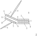
- Fig. 1 shows a schematic diagram of a MIMO base station antenna 100 according to an embodiment.
- the MIMO base station antenna 100 is configured for handling beamforming communications towards areas that are below and above the base station antenna, for example towards a cell area with a user equipment (UE) located below the base station antenna comprising, and towards a high building or a drone.
- UE user equipment
- the MIMO base station antenna 100 comprises an antenna mounting frame 101 having an elongated base portion 103, e.g. with rectangular or circular cross section, and a tilted base portion 105 extending from the elongated base portion 103, wherein the tilted base portion 105 has a first planar surface 107 and a second planar surface 109, the first planar surface 107 and the second planar surface 109 facing away from each other, wherein the first planar surface 107 is directed downwardly and wherein the second planar surface 109 is directed upwardly, for e.g. communicating with a drone.
- the MIMO base station antenna 100 further comprises a first array of antenna elements 111 arranged on or within the first planar surface 107, the first array of antenna elements 111 being configured for generating a downward transmission beam 112, and a second array of antenna elements 113 arranged on or within the second planar surface 109, the second array of antenna elements being configured for generating an upward transmission beam 114.
- the antenna mounting frame 101 can be made of metal or plastic.
- the respective array of antenna elements 111, 113 can be embedded or mechanically attached to the respective planar surface 107, 109.
- the first array of antenna elements 111 and the second array of antenna elements 113 are jointly configured for communications according to one of the following communication technologies: GSM, LTE, LTE-A, UMTS, HSPA, 3GPP, in particular 3GPP NR, New Radio, 5G or IEEE radio systems such as Wireless LAN, WiGig, or any of the evolutions and successors of these technologies.
- Fig. 2 shows a MIMO base station antenna 100 in an embodiment, wherein a third array of antenna elements 117 is arranged on the elongated base portion 103.
- the third array of antenna elements 117 can be e.g. provided for conventional communications without beamforming, e.g. at 1.8 GHz.
- the third array of antenna elements 117 can have a directional characteristic, which is broader than e.g. the downward transmission beam 112.
- a plurality, e.g. 3, of third arrays of antenna elements 117 can be provided that are arranged circumferentially around the elongated base portion 103.
- the respective third array of antenna elements 113 can be provided for broadcasting control information such as BCCH information, paging requests or voice communications. Moreover, the respective third array of antenna elements 117 can be provided for e.g. GSM or LTE communications at 1.8 GHz, whereas the first and second array of antenna elements 111, 113 can support 5G communications using beamforming in the frequency range 3.4 to 3.8 GHz, or 24.25 to 29.5 GHz or 31.8 to 33.4 GHz or 37 to 40 GHz or 57 to 77 GHz.
- the respective third array of antenna elements 113 can also be provided for sideward communications.
- Fig. 3a and 3b show front views of the MIMO base station antenna 100. As depicted in Fig. 3a , the elongated base portion 103 is narrower than the tilted base portion 105.
- the elongated base portion 103 and the tilted base portion 105 have the same width.
- the first array of antenna elements 111 and the second array of antenna elements 113 are arranged to form rows and columns of discrete elements, which can be embedded in the respective planar surface 107 and 109.
- Fig. 4 shows a MIMO base station system 200 for handling cellular communications, comprising a base station 201 and the MIMO base station antenna 100.
- the MIMO base station system 200 is configured to steer each array of antenna elements 111, 113 or to jointly steer the first array of antenna elements 111 and the second array of antenna elements 113 of the base station antenna 100 for generating the respective transmission beam 112, 114 or for receiving a reception beam upon the basis of a predetermined MIMO codebook, in particular a MIMO codebook according to the 5G technology.
- the MIMO codebook can in indicate phases, e.g. 1 + 1j, for driving the arrays or sub-arrays of antenna elements 111 and the second array of antenna elements 113 to generate spatially directed beams.
- Fig. 5 shows a diagram of a beamforming communication method 300 performed by the MIMO base station system, comprising generating 301, by the MIMO base station antenna 100, a downward transmission beam for mobile communications below the MIMO base station antenna 100, and generating 303, by the MIMO base station antenna 100, an upward transmission beam for mobile communications above the MIMO base station antenna 100 in particular for drone communications.
- the method 300 can be implemented in software on the MIMO base station 200.
Landscapes
- Engineering & Computer Science (AREA)
- Computer Networks & Wireless Communication (AREA)
- Radio Transmission System (AREA)
- Mobile Radio Communication Systems (AREA)
Abstract
The invention relates to a multiple-in multiple-out (MIMO) base station antenna (100) for handling beamforming communications towards areas that are below and above the base station antenna, the base station antenna comprising: an antenna mounting frame (101) an elongated base portion (103) and a tilted base portion (105) extending from the elongated base portion (103), wherein the tilted base portion (105) has a first planar surface (107) and a second planar surface (109), the first planar surface (107) and the second planar surface (109) facing away from each other, wherein the first planar surface (107) is directed downwardly and wherein the second planar surface (109) is directed upwardly; a first array of antenna elements (111) arranged on or within the first planar surface (107), the first array of antenna elements (111) being configured for generating a downward transmission beam; and a second array of antenna elements (113) arranged on or within the second planar surface (109), the second array of antenna elements (113) being configured for generating an upward transmission beam.
Description
- In general, the present invention relates to the field of beamforming antennas, in particular for multiple-in multiple-out (MIMO) communications.
- Mobile communications in urban areas are usually supported by base stations having elevated antennas, which are e.g. arranged on a roof of a building. However, in beamforming communications where a base station transmits a dedicated transmission beam towards a cell area associated with the base station, which cell area and user equipment (UE) located in the cell area are usually located below the base station antenna. Therefore, measures must be taken to direct the transmission beam downwardly towards the UE, or to receive a reception beam from the UE that is located below the antenna.
- Traditionally, MIMO beamforming antennas are formed by planar panels having an array of antenna elements arranged in the planar panel. The radiation space is therefore a half-space limited by the plane in which the antenna elements are arranged.
- The antenna elements or sub-arrays of antenna elements can separately be driven using e.g. a steering signal with a predetermined phase in order to generate a transmission beam towards a certain direction.
- In order to direct the transmission beams towards UEs that are below the elevated antenna, the down tilt can be provided by either mechanically tilting the planar panel downwards, or by electrically tilting the transmission beams by appropriately steering the antenna elements.
- However, in both cases the down tilt disables beamforming communications with objects arranged above the beamforming antenna, in particular flying objects such as drones.
- It is therefore an object of the disclosure to provide an improved base station antenna, simultaneously allowing beam transmission with UEs arranged below the base station antenna and drones flying above the base station antenna.
- The foregoing and other objects are achieved by the subject matter of the independent claims. Further implementation forms are apparent from the dependent claims, the description and the figures.
- Generally, the invention relates to a multiple-in-multiple-out (MIMO) base station antenna and multiple-in-multiple-out (MIMO) base station for communications using beamforming.
- According to a first aspect, the disclosure relates to a multiple-in multiple-out (MIMO) base station antenna for handling beamforming communications towards areas that are below and above the base station antenna, the base station antenna comprising: an antenna mounting frame having a mounting foot, an elongated base portion and a tilted base portion extending from the elongated base portion, wherein the tilted base portion has a first planar surface and a second planar surface, the first planar surface and the second planar surface facing away from each other, wherein the first planar surface is directed downwardly and wherein the second planar surface is directed upwardly; a first array of antenna elements arranged on or within the first planar surface, the first array of antenna elements being configured for generating a downward transmission beam; and a second array of antenna elements arranged on or within the second planar surface, the second array of antenna elements being configured for generating an upward transmission beam for drone communications.
- Thereby, simultaneous coverage of urban areas even with very high buildings and communications with drones or other aerial objects can be provided.
- The respective array of antenna elements can correspondingly receive reception beams.
- According to an example, the first array of antenna elements and the second array of antenna elements form separately controllable arrays of antenna elements, and/or the first array of antenna elements and the second array of antenna elements form a composite array of antenna elements.
- According to an example, the first array of antenna elements and the second array of antenna elements form separately controllable arrays of antenna elements, and wherein the first array of antenna elements has a first terminal for receiving a first steering signal to generate the downward transmission beam, and wherein the second array of antenna elements has a second terminal for receiving a second steering signal to generate the upward transmission beam.
- According to an example, the first array of antenna elements and the second array of antenna elements form a composite array of antenna elements, wherein the antenna elements or sub-arrays of antenna elements are individually addressable by a steering signal. Thereby, a transmission beam sweeping between the arrays of antenna elements can be realized.
- According to an example, the first array of antenna elements and the second array of antenna elements are configured to continuously change a direction of beam transmission or beam reception in a vertical plane in an angular range greater than 180°, in particular in order to track movement of a flying object, e.g. a drone.
- According to an example, the first array of antenna elements is configured to transmit the downward transmission beam towards a cell area extending below the base station antenna, and/or wherein the second array of antenna elements is configured to transmit the upward transmission beam towards a cell area extending above the base station antenna, in particular towards an flying object, e.g. a drone or towards a building extending above the base station antenna.
- According to an example, the first array of antenna elements and the second array or antenna elements are configured to simultaneously transmit the upward transmission beam and the downward transmission beam.
- According to an example, the MIMO further comprises a third array of antenna elements attached to the elongated base portion.
- According to an example, the first array of antenna elements and the second array of antenna elements are configured for communications in a first frequency range, in particular 3.4 to 3.8 GHz, or 24.25 to 29.5 GHz or 31.8 to 33.4GHz or 37 to 40 GHz or 57 to 77 GHz, that differs from a second frequency range, in particular 0.8, 0.9, 1.8 GHz and 2.1 GHz of the third array of antenna elements.
- According to an example, the third array of antenna elements forms an omnidirectional or a directional antenna for broadcasting or a beamforming antenna for generating a sideward transmission beam.
- According to an example, the first array of antenna elements and the second array of antenna elements are configured for data communications, and wherein the third array of antenna elements is configured for voice communications of control communications, in particular for paging or signalling communication parameters such as BCCH or PBCCH (Physical Broadcast Channel) parameters or Broadcast Channel Master Information Block (MIB), System Information Block (SIB), cell identification, Public Land Mobile Network (PLMN) configuration, Random Access Channel (RACH) configuration, base station identification, location area information, indication of communication channels, indication of communication frequencies, indication of neighbor cell information, indication of communication technology associated with a MIMO base station, in particular 5G from the broadcast transmitter in the communication cell.
- According to an example, the first array of antenna elements and the second array of antenna elements are jointly configured for communications according to a first communication technology, and wherein the third array of antenna elements is configured for communications according to a second communication technology, wherein the first communication technology and the second communication technology are different or the same communication technologies.
- According to an example, the first communication technology and the second communication technology are one of the following communication technologies: GSM, LTE, LTE-A, UMTS, HSPA, 3GPP, in particular 3GPP NR, New Radio, 5G or IEEE radio systems such as Wireless LAN, WiGig, or any of the evolutions and successors of these technologies.
- According to an example, the MIMO base station antenna comprises a plurality of third arrays of antenna elements that are arranged circumferentially around the elongated base portion.
- According to an example, the MIMO base station antenna comprises a plurality of antenna mounting frames, each having a mounting foot, an elongated base portion and a tilted base portion extending from the elongated base portion, each tilted base portion having a first planar surface and a second planar surface, the first planar surface and the second planar surface facing away from each other, wherein the first planar surface is directed downwardly and wherein the second planar surface is directed upwardly, wherein each first planar surface has a first array of antenna elements being configured for generating a downward transmission beam, wherein each second planar surface has a second array of antenna elements being configured for generating an upward transmission beam; wherein the antenna mounting frames are arranged such that the tilted base portions are facing in different directions, in particular such that the surface normal vectors of the second surfaces are tilted towards each other.
- According to an example, the antenna mounting frame is a one-piece mounting frame, or wherein the tilted base portion is mechanically attached to the elongated base portion.
- According to an example, the respective array of antenna elements is attached to the respective planar surface or embedded within the respective planar surface.
- According to an example, respective array of antenna elements comprises at least 16 antenna elements, for generating a transmission beam or for receiving a reception beam, wherein the antenna elements responsive to steering signals with of e.g. a MIMO codebook according to the 5G technology. The codebook indicates for example phase shifts, e. g. 1 + j1, for each antenna element in order to generate a spatially directed transmission or reception beam.
- In a further possible implementation form of the first aspect, the respective broadcast transmitter comprises a memory with pre-stored control information relating to the MIMO base station.
- According to a second aspect, the disclosure relates to a MIMO base station system for handling cellular communications, the base station system comprising a base station; and the MIMO base station antenna according to the first aspect.
- According to an example, the base station is configured to provide generate a steer each array of antenna elements or to jointly steer the first array of antenna elements and the second array of antenna elements of the base station antenna for generating the respective transmission beam or for receiving a reception beam upon the basis of a predetermined MIMO codebook, in particular a MIMO codebook according to the 5G technology.
- According to an example, the MIMO base station system is configured to handle communications in the communication cell using beamforming according the fifth generation (5G) communication technology or higher, and/or wherein the respective broadcast transmitter is configured to broadcast the control information according to one of the following communication technologies: GSM, LTE, LTE-A, UMTS, HSPA, 3GPP, in particular 3GPP NR, New Radio, 5G or IEEE radio systems such as Wireless LAN, WiGig, or any of the evolutions and successors of these technologies.
- According to a third aspect, the disclosure relates to a beamforming communication method performed by the MIMO base station system according to the second aspect or by the MIMO base station antenna according to the first aspect, the method comprising: generating a downward transmission beam for mobile communications below the MIMO base station antenna by the MIMO base station antenna; and generating an upward transmission beam for mobile communications above the MIMO base station antenna by the MIMO base station antenna, in particular for drone communications.
- According to a fourth aspect, the disclosure relates to a computer program product comprising a program code for performing the method of the third aspect when executed on the MIMO base station of the MIMO base station system according to the second aspect.
- Further embodiments of the invention will be described with respect to the following figures, wherein:
-
Fig. 1 shows an example of the MIMO base station antenna according to an embodiment; -
Fig. 2 shows an example of the MIMO base station antenna according to an embodiment; -
Fig. 3a and 3b show front views of the MIMO base station antenna; -
Fig. 4 shows an example of a MIMO base station system; -
Fig. 5 shows a diagram of a beamforming communication method. - In the various figures, identical reference signs will be used for identical or at least functionally equivalent features.
- In the following description, reference is made to the accompanying drawings, which form part of the disclosure, and in which are shown, by way of illustration, specific aspects in which the present invention may be placed. It will be appreciated that other aspects may be utilized and structural or logical changes may be made without departing from the scope of the present invention. The following detailed description, therefore, is not to be taken in a limiting sense, as the scope of the present invention is defined by the appended claims.
- For instance, it will be appreciated that a disclosure in connection with a described method may also hold true for a corresponding device or system configured to perform the method and vice versa. For example, if a specific method step is described, a corresponding device may include a unit to perform the described method step, even if such unit is not explicitly described or illustrated in the figures.
- Moreover, in the following detailed description as well as in the claims, embodiments with different functional blocks or processing units are described, which are connected with each other or exchange signals. It will be appreciated that the present invention covers embodiments as well, which include additional functional blocks or processing units that are arranged between the functional blocks or processing units of the embodiments described below.
- Finally, it is understood that the features of the various exemplary aspects described herein may be combined with each other, unless specifically noted otherwise.
-
Fig. 1 shows a schematic diagram of a MIMObase station antenna 100 according to an embodiment. - The MIMO
base station antenna 100 is configured for handling beamforming communications towards areas that are below and above the base station antenna, for example towards a cell area with a user equipment (UE) located below the base station antenna comprising, and towards a high building or a drone. - The MIMO
base station antenna 100 comprises anantenna mounting frame 101 having anelongated base portion 103, e.g. with rectangular or circular cross section, and atilted base portion 105 extending from theelongated base portion 103, wherein thetilted base portion 105 has a firstplanar surface 107 and a secondplanar surface 109, the firstplanar surface 107 and the secondplanar surface 109 facing away from each other, wherein the firstplanar surface 107 is directed downwardly and wherein the secondplanar surface 109 is directed upwardly, for e.g. communicating with a drone. - The MIMO
base station antenna 100 further comprises a first array ofantenna elements 111 arranged on or within the firstplanar surface 107, the first array ofantenna elements 111 being configured for generating adownward transmission beam 112, and a second array ofantenna elements 113 arranged on or within the secondplanar surface 109, the second array of antenna elements being configured for generating anupward transmission beam 114. - The
antenna mounting frame 101 can be made of metal or plastic. The respective array ofantenna elements planar surface - According to an embodiment, the first array of
antenna elements 111 and the second array ofantenna elements 113 are jointly configured for communications according to one of the following communication technologies: GSM, LTE, LTE-A, UMTS, HSPA, 3GPP, in particular 3GPP NR, New Radio, 5G or IEEE radio systems such as Wireless LAN, WiGig, or any of the evolutions and successors of these technologies. -
Fig. 2 shows a MIMObase station antenna 100 in an embodiment, wherein a third array ofantenna elements 117 is arranged on theelongated base portion 103. The third array ofantenna elements 117 can be e.g. provided for conventional communications without beamforming, e.g. at 1.8 GHz. - The third array of
antenna elements 117 can have a directional characteristic, which is broader than e.g. thedownward transmission beam 112. In order to provide a coverage at 360°, a plurality, e.g. 3, of third arrays ofantenna elements 117 can be provided that are arranged circumferentially around theelongated base portion 103. - The respective third array of
antenna elements 113 can be provided for broadcasting control information such as BCCH information, paging requests or voice communications. Moreover, the respective third array ofantenna elements 117 can be provided for e.g. GSM or LTE communications at 1.8 GHz, whereas the first and second array ofantenna elements - The respective third array of
antenna elements 113 can also be provided for sideward communications. -
Fig. 3a and 3b show front views of the MIMObase station antenna 100. As depicted inFig. 3a , theelongated base portion 103 is narrower than the tiltedbase portion 105. - As depicted in
Fig. 3b , theelongated base portion 103 and the tiltedbase portion 105 have the same width. - As exemplarily depicted in
Figs. 3a and 3b , the first array ofantenna elements 111 and the second array ofantenna elements 113 are arranged to form rows and columns of discrete elements, which can be embedded in the respectiveplanar surface -
Fig. 4 shows a MIMObase station system 200 for handling cellular communications, comprising a base station 201 and the MIMObase station antenna 100. - The MIMO
base station system 200 is configured to steer each array ofantenna elements antenna elements 111 and the second array ofantenna elements 113 of thebase station antenna 100 for generating therespective transmission beam antenna elements 111 and the second array ofantenna elements 113 to generate spatially directed beams. -
Fig. 5 shows a diagram of abeamforming communication method 300 performed by the MIMO base station system, comprising generating 301, by the MIMObase station antenna 100, a downward transmission beam for mobile communications below the MIMObase station antenna 100, and generating 303, by the MIMObase station antenna 100, an upward transmission beam for mobile communications above the MIMObase station antenna 100 in particular for drone communications. - The
method 300 can be implemented in software on theMIMO base station 200. - While a particular feature or aspect of the disclosure may have been disclosed with respect to only one of several implementations or embodiments, such feature or aspect may be combined with one or more other features or aspects of the other implementations or embodiments as may be desired and advantageous for any given or particular application. Furthermore, to the extent that the terms "include", "have", "with", or other variants thereof are used in either the detailed description or the claims, such terms are intended to be inclusive in a manner similar to the term "comprise". Also, the terms "exemplary", "for example" and "e.g." are merely meant as an example, rather than the best or optimal. The terms "coupled" and "connected", along with derivatives may have been used. It should be understood that these terms may have been used to indicate that two elements cooperate or interact with each other regardless of whether they are in direct physical or electrical contact, or they are not in direct contact with each other.
- Although specific aspects have been illustrated and described herein, it will be appreciated by those of ordinary skill in the art that a variety of alternate and/or equivalent implementations may be substituted for the specific aspects shown and described without departing from the scope of the present disclosure. This application is intended to cover any adaptations or variations of the specific aspects discussed herein.
- Although the elements in the following claims are recited in a particular sequence with corresponding labeling, unless the claim recitations otherwise imply a particular sequence for implementing some or all of those elements, those elements are not necessarily intended to be limited to being implemented in that particular sequence.
- Many alternatives, modifications, and variations will be apparent to those skilled in the art in light of the above teachings. Of course, those skilled in the art readily recognize that there are numerous applications of the invention beyond those described herein. While the present invention has been described with reference to one or more particular embodiments, those skilled in the art recognize that many changes may be made thereto without departing from the scope of the present invention. It is therefore to be understood that within the scope of the appended claims and their equivalents, the invention may be practiced otherwise than as specifically described herein.
Claims (15)
- A multiple-in multiple-out (MIMO) base station antenna (100) for handling beamforming communications towards areas that are below and above the base station antenna, the base station antenna comprising:an antenna mounting frame (101) comprising an elongated base portion (103) and a tilted base portion (105) extending from the elongated base portion (103), wherein the tilted base portion (105) has a first planar surface (107) and a second planar surface (109), the first planar surface (107) and the second planar surface (109) facing away from each other, wherein the first planar surface (107) is directed downwardly and wherein the second planar surface (109) is directed upwardly;a first array of antenna elements (111) arranged on or within the first planar surface (107), the first array of antenna elements (111) being configured for generating a downward transmission beam; anda second array of antenna elements (113) arranged on or within the second planar surface (109), the second array of antenna elements (113) being configured for generating an upward transmission beam.
- The MIMO base station antenna (100) according to claim 1, wherein the first array of antenna elements (111) and the second array of antenna elements (113) form separately controllable arrays of antenna elements (111, 113), and wherein the first array of antenna elements (111) has a first terminal for receiving a first steering signal to generate the downward transmission beam, and wherein the second array of antenna elements (113) has a second terminal for receiving a second steering signal to generate the upward transmission beam, or wherein the first array of antenna elements (111) and the second array of antenna elements (113) form a composite array of antenna elements (111, 113), wherein the antenna elements (111, 113), or sub-arrays of antenna elements (111, 113), are individually addressable by a steering signal.
- The MIMO base station antenna (100) according to anyone of the preceding claims, wherein the first array of antenna elements (111) and the second array of antenna elements (113) are configured to continuously change a direction of beam transmission or beam reception in a vertical plane in an angular range greater than 180°, in particular in order to track movement of a flying object, e.g. a drone.
- The MIMO base station antenna (100) according to anyone of the preceding claims, wherein the first array of antenna elements (111) and the second array or antenna elements (113) are configured to simultaneously transmit the upward transmission beam and the downward transmission beam.
- The MIMO base station antenna (100) according to anyone of the preceding claims, further comprising a third array of antenna elements (117) attached to the elongated base portion (103).
- The MIMO base station antenna (100) according to claim 5, wherein the first array of antenna elements (111) and the second array of antenna elements (113) are configured for communications in a first frequency range, in particular 3.4 GHz to 3.8 GHz, or 24.25 GHz to 29.5 GHz or 31.8 GHz to 33.4 GHz or 37 GHz to 40 GHz or 57 GHz to 77 GHz, wherein the third array of antenna elements (117) is configured for communications in a second frequency range, in particular 0.8 GHz, 0.9 GHz, 1.8 GHz and 2.1 GHz, and wherein the first frequency range differs from the second frequency range.
- The MIMO base station antenna (100) according to claim 5 or 6, wherein the third array of antenna elements (117) forms an omnidirectional or a directional antenna for broadcasting or a beamforming antenna for generating a sideward transmission beam.
- The MIMO base station antenna (100) according to claim 5, 6 or 7, wherein the first array of antenna elements (111) and the second array of antenna elements (113) are configured for data communications, and wherein the third array of antenna elements (117) is configured for voice communications of control communications, in particular for paging or signalling communication parameters such as BCCH parameters.
- The MIMO base station antenna (100) according anyone of the claims 5 to 8, wherein the first array of antenna elements (111) and the second array or antenna elements (113) are jointly configured for communications according to a first communication technology, and wherein the third array of antenna elements (117) is configured for communications according to a second communication technology, wherein the first communication technology and the second communication technology are different or the same communication technologies.
- The MIMO base station antenna (100) according to claim 9, the first communication technology and the second communication technology being one of the following communication technologies: GSM, LTE, LTE-A, UMTS, HSPA, 3GPP, in particular 3GPP NR, New Radio, 5G or IEEE radio systems such as Wireless LAN, WiGig, or any of the evolutions and successors of these technologies.
- The MIMO base station antenna (100) according to anyone of the preceding claims, comprising a plurality of antenna mounting frames (101), each having an elongated base portion (103) and a tilted base portion (105) extending from the elongated base portion (103), each tilted base portion (105) having a first planar surface (107) and a second planar surface (109), the first planar surface (107) and the second planar surface 109) facing away from each other, wherein each first planar surface (107) is directed downwardly and wherein each second planar surface (109) is directed upwardly, wherein each first planar surface (107) has a first array of antenna elements (111) being configured for generating a downward transmission beam, wherein each second planar surface (107) has a second array of antenna elements (113) being configured for generating an upward transmission beam; wherein
the antenna mounting frames (101) are arranged such that the tilted base portions (105) are facing in different directions, in particular such that the surface normal vectors of the second planar surfaces (109) are tilted towards each other. - The MIMO base station antenna (100) according to anyone of the preceding claims, wherein the respective array of antenna elements (111, 113, 117) is attached to the respective planar surface (107, 109) or embedded within the respective planar surface (107, 109).
- A MIMO base station system (200) for handling cellular communications, the MIMO base station system comprising:a MIMO base station (201); andthe MIMO base station antenna (100) according to anyone of the claims 1 to 12.
- Beamforming communication method (300) performed by the MIMO base station system (200) according to claim 13, comprising:Generating (301), by the MIMO base station antenna (100), a downward transmission beam for mobile communications below the MIMO base station antenna; andGenerating (303), by the MIMO base station antenna (100) an upward transmission beam for mobile communications above the MIMO base station antenna, in particular for drone communications.
- Computer program product comprising a program code for performing the method of claim 14 when executed on the MIMO base station of the MIMO base station system according to claim 13.
Priority Applications (2)
| Application Number | Priority Date | Filing Date | Title |
|---|---|---|---|
| EP17210459.8A EP3503285A1 (en) | 2017-12-22 | 2017-12-22 | Base station antenna |
| PCT/EP2018/081152 WO2019120763A1 (en) | 2017-12-22 | 2018-11-14 | Base station antenna |
Applications Claiming Priority (1)
| Application Number | Priority Date | Filing Date | Title |
|---|---|---|---|
| EP17210459.8A EP3503285A1 (en) | 2017-12-22 | 2017-12-22 | Base station antenna |
Publications (1)
| Publication Number | Publication Date |
|---|---|
| EP3503285A1 true EP3503285A1 (en) | 2019-06-26 |
Family
ID=60811937
Family Applications (1)
| Application Number | Title | Priority Date | Filing Date |
|---|---|---|---|
| EP17210459.8A Ceased EP3503285A1 (en) | 2017-12-22 | 2017-12-22 | Base station antenna |
Country Status (2)
| Country | Link |
|---|---|
| EP (1) | EP3503285A1 (en) |
| WO (1) | WO2019120763A1 (en) |
Citations (5)
| Publication number | Priority date | Publication date | Assignee | Title |
|---|---|---|---|---|
| US6448930B1 (en) * | 1999-10-15 | 2002-09-10 | Andrew Corporation | Indoor antenna |
| DE102005063443A1 (en) * | 2004-03-31 | 2008-01-03 | Mario Lehmann | Communication center for use in mobile network, has modules connected to guiding wires via direct current power supply unit and interconnected wirelessly by standard bus system for analog signals and/or internet protocol based data |
| US20140274076A1 (en) * | 2013-03-15 | 2014-09-18 | Smartsky Networks LLC | Concentric cells in a wireless communication system |
| US20150236778A1 (en) * | 2014-02-17 | 2015-08-20 | Ubiqomm Llc | Broadband access to mobile platforms using drone/uav background |
| CN205690233U (en) * | 2016-06-13 | 2016-11-16 | 上海飞乐智能技术有限公司 | A kind of intelligent LED street lamp |
-
2017
- 2017-12-22 EP EP17210459.8A patent/EP3503285A1/en not_active Ceased
-
2018
- 2018-11-14 WO PCT/EP2018/081152 patent/WO2019120763A1/en not_active Ceased
Patent Citations (5)
| Publication number | Priority date | Publication date | Assignee | Title |
|---|---|---|---|---|
| US6448930B1 (en) * | 1999-10-15 | 2002-09-10 | Andrew Corporation | Indoor antenna |
| DE102005063443A1 (en) * | 2004-03-31 | 2008-01-03 | Mario Lehmann | Communication center for use in mobile network, has modules connected to guiding wires via direct current power supply unit and interconnected wirelessly by standard bus system for analog signals and/or internet protocol based data |
| US20140274076A1 (en) * | 2013-03-15 | 2014-09-18 | Smartsky Networks LLC | Concentric cells in a wireless communication system |
| US20150236778A1 (en) * | 2014-02-17 | 2015-08-20 | Ubiqomm Llc | Broadband access to mobile platforms using drone/uav background |
| CN205690233U (en) * | 2016-06-13 | 2016-11-16 | 上海飞乐智能技术有限公司 | A kind of intelligent LED street lamp |
Also Published As
| Publication number | Publication date |
|---|---|
| WO2019120763A1 (en) | 2019-06-27 |
Similar Documents
| Publication | Publication Date | Title |
|---|---|---|
| US9960823B2 (en) | Method and apparatus for scheduling beam in mobile communication system of ultrahigh frequency wave band | |
| CN100488076C (en) | Intellectual antenna array and improvement concerned | |
| US11309618B2 (en) | Antenna array and method for manufacturing thereof | |
| KR102080037B1 (en) | Access Nodes and Beamforming Method for Receiving and Transmitting Signals in Wireless Communication Network | |
| EP3218962B1 (en) | Array antennas including non-uniform antenna elements | |
| EP3394958A1 (en) | Phased array antenna having sub-arrays | |
| CN103443997A (en) | Antenna array for supporting multiple beam architectures | |
| JP2017169067A (en) | Base station device and radio control method | |
| US20060084474A1 (en) | Method and system for managing a cell sectorized by both an angle in azimuth and a distance from a base station | |
| EP3503298A1 (en) | Base station antenna for cellular communications | |
| WO2000051367A2 (en) | Smart antenna beam assignment at mobile station call setup | |
| US12309757B2 (en) | Base station and radio communication system | |
| WO2019120763A1 (en) | Base station antenna | |
| US20260088491A1 (en) | Self-organizing directional antenna system for radio stations | |
| US20240380468A1 (en) | Flexible antenna configurations | |
| EP1226724B1 (en) | Method and apparatus for providing forward link softer handoff in a code division multiple access communication system | |
| EP3503422A1 (en) | Base station system for handling radio communications of a user entity | |
| JP2019110399A (en) | Antenna device and antenna directivity control method | |
| EP1226723A4 (en) | Method and apparatus for providing forward link softer handoff in a code division multiple access communication system | |
| JP6833910B2 (en) | Access node and beam forming methods for receiving and transmitting signals in wireless communication networks | |
| EP3503638A1 (en) | Base station system for handling a paging request towards a user entity | |
| EP3503420A1 (en) | Base station system for transmitting data towards a user entity | |
| EP3503421A1 (en) | Base station system for transmitting data towards a user entity | |
| HK1232049A1 (en) | Access nodes and beamforming method for receiving and transmitting signals in wireless communication network | |
| Ginard et al. | Enhancing cellular vehicular uplink performance: experimental evaluation of switching antenna system |
Legal Events
| Date | Code | Title | Description |
|---|---|---|---|
| STAA | Information on the status of an ep patent application or granted ep patent |
Free format text: STATUS: EXAMINATION IS IN PROGRESS |
|
| PUAI | Public reference made under article 153(3) epc to a published international application that has entered the european phase |
Free format text: ORIGINAL CODE: 0009012 |
|
| 17P | Request for examination filed |
Effective date: 20181010 |
|
| AK | Designated contracting states |
Kind code of ref document: A1 Designated state(s): AL AT BE BG CH CY CZ DE DK EE ES FI FR GB GR HR HU IE IS IT LI LT LU LV MC MK MT NL NO PL PT RO RS SE SI SK SM TR |
|
| AX | Request for extension of the european patent |
Extension state: BA ME |
|
| STAA | Information on the status of an ep patent application or granted ep patent |
Free format text: STATUS: THE APPLICATION HAS BEEN REFUSED |
|
| 18R | Application refused |
Effective date: 20191118 |